ELFE4222WH - Dryer ELECTROLUX - Free user manual and instructions
Find the device manual for free ELFE4222WH ELECTROLUX in PDF.

User questions about ELFE4222WH ELECTROLUX
0 question about this device. Answer the ones you know or ask your own.
Ask a new question about this device
Download the instructions for your Dryer in PDF format for free! Find your manual ELFE4222WH - ELECTROLUX and take your electronic device back in hand. On this page are published all the documents necessary for the use of your device. ELFE4222WH by ELECTROLUX.
USER MANUAL ELFE4222WH ELECTROLUX
2 Important Safety Instructions

WARNING
Please read all instructions before using this dryer.
Recognize Safety Symbols, Words and Labels
Safety items throughout this manual are labeled with a WARNING or CAUTION based on the risk type as described below:
Definitions
This is the safety alert symbol. It is used to alert you to potential personal injury hazards. Obey all safety messages that follow this symbol to avoid possible injury or death.

DANGER
DANGER indicates an imminently hazardous situation which, if not avoided, will result in death or serious injury.

WARNING
WARNING indicates a potentially hazardous situation which, if not avoided, could result in death or serious injury.

CAUTION
CAUTION indicates a potentially hazardous situation which, if not avoided, may result in minor or moderate injury.

IMPORTANT
Indicates installation, operation, or maintenance information which is important but not hazard-related.
Table of Contents
Important Safety Instructions ....2
Installation Requirements ....4
Installation Instructions ....8
Reversing Door 15
Accessories....17
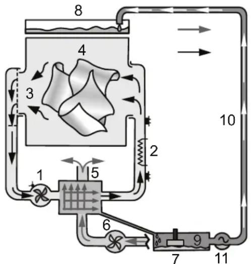
Thank you for choosing an Electrolux Compact Ventless Dryer. This dryer operates on a different drying principle than traditional exhaust ducted dryers. Your new dryer is a condensation, ventless dryer and DOES NOT require exhaust venting that exhausts the drying process air to the outside.
A condensation dryer works through a closed loop circuit. The drying process air is heated by an internal heating element, which then passes over and through your clothes. The moisture rich air proceeds down through a lint filter, then through an air-air heat exchanger that works as a condenser. The warm, wet air is cooled by a separate secondary fan that utilizes ambient room air. When the process air cools down, it releases moisture that is collected in a recovery basin at the bottom of the appliance. The water can be either pumped down the drain by the provided kit, or pumped directly into a tank that needs to be emptied after each drying cycle.

IMPORTANT
Your new dryer is a condensation, ventless dryer and DOES NOT require exhaust venting that exhausts the drying process air to the outside.
flowchart
graph TD
    A["1"] --> B["2"]
    B --> C["3"]
    C --> D["4"]
    D --> E["5"]
    E --> F["6"]
    F --> G["7"]
    G --> H["8"]
    H --> I["9"]
    I --> J["10"]
    style A fill:#f9f,stroke:#333
    style J fill:#f9f,stroke:#333
- Primary circuit – drying process air fan
- Heating element
- Lint filter
- Clothes load
-
Heat exchanger
-
Secondary circuit – ambient air fan
- Drain water basin
- Water tank
- Float/pump switch
- Water drain tube
- Water pump

WARNING
For your safety the information in this manual must be followed to minimize the risk of fire or explosion or to prevent property damage, personal injury or loss of life. Do not store or use gasoline or other flammable vapors and liquids in the vicinity of this or any other appliance.

WARNING
RISK OF FIRE
Read all the following instructions before installing and using this appliance.
- Recycle the carton and dispose of plastic bags after the dryer is unpacked. Children might use them to play. Cartons covered with rugs, bedspreads, or plastic sheets can become airtight chambers causing suffocation. Place all materials in a garbage container or make materials inaccessible to children.
- Clothes dryer installation and service must be performed by a qualified installer or service agency.
- Install the clothes dryer according to the manufacturer's instructions and local codes.
- The electrical service to the dryer must conform with local codes and ordinances and the latest edition of the National Electrical Code, ANSI/NFPA 70, or in Canada, the Canadian Electrical Code CSA C22.1 part 1.
- The dryer is designed under ANSI Z21.5.1/CSA 7.1 or UL 2158 - CAN/CSA C22.2 No. 112 (latest editions) for HOME USE only. This dryer is not recommended for commercial applications such as restaurants, beauty salons, etc.
- DO NOT stack a dryer on top of washer already installed on pedestal. DO NOT stack dryer on top of another dryer. DO NOT stack washer on top of dryer. DO NOT stack washer on top of another washer. DO NOT stack dryer on top of washer without use of manufacturer approved and correctly installed stacking kit appropriate for your model.
The instructions in this manual and all other literature included with this dryer are not meant to cover every possible condition and situation that may occur. Good safe practice and caution MUST be applied when installing, operating and maintaining any appliance.

CAUTION
EXCESSIVE WEIGHT HAZARD
To avoid back or other injury, have more than one person move or lift the dryer.

IMPORTANT
DO NOT INSTALL YOUR DRYER:
- In an area exposed to dripping water or outside weather conditions.
- On carpet. Floor MUST be solid with a maximum slope of 1 inch (2.5 cm).

WARNING
EXPLOSION HAZARD
Do not install the dryer where gasoline or other flammables are kept or stored. If the dryer is installed in a garage, it must be a minimum of 18 inches (45.7 cm) above the floor. Failure to do so can result in death, explosion, fire or burns.
SAVE THESE INSTRUCTIONS FOR FUTURE REFERENCE.
4
Installation Requirements
Please Read and Save this Guide
Thank you for choosing Electrolux, the premium brand in home appliances. These Installation Instructions are part of our commitment to customer satisfaction and product quality throughout the life of your new appliance.
Questions?
Toll-free telephone and online support:
U.S.:1-877-4ELECTROLUX
(1-877-435-3287)
www.electroluxappliances.com
Canada: 1-800-265-8352
www.electroluxappliances.ca

Installation Checklist
Unpacking
☐ Plastic film (lining drum interior) is removed and discarded. See also image below.
Leveling
☐ Dryer is level, side-to-side and front-to-back
□ Cabinet is setting solid on all corners
208v/240v Electric Supply
☐ Approved NEMA 10-30 or 14-30 service cord with all screws tight on terminal block
☐ Terminal access cover/strain relief installed before initial operation
Note: Dryers operating on 208 volt power supply will have longer drying times than dryers operating on 240 volt power supply.
Door Reversal
☐ Follow detailed instructions in this guide
☐ Test hinge and latch for function
Electrical Power
House power turned on
Dryer plugged in
Final Checks
☐ Installation Instructions and Use & Care Guide read thoroughly
☐ Door latches and drum tumbles when cycle starts
☐ Registration card sent in
Tools and Materials Needed for Installation:
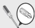
Phillips
screwdriver
AND

Optional universal wrench
OR
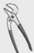
Adjustable pliers
Carpenter's level
AND
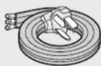
3- or 4-wire
240 volt cord kit
Electrical Requirements for Electric Dryer

NOTE
Because of potentially inconsistent voltage capabilities, the use of this dryer with power created by gas powered generators, solar powered generators, wind powered generators or any other generator other than the local utility company is not recommended.
CIRCUIT - Individual 30 amp. branch circuit fused with 30 amp. time delay fuses or circuit breakers. Use separately fused circuits for washer and dryer. DO NOT operate a washer and a dryer on the same circuit.
POWER SUPPLY - 3-wire or 4-wire, 208-240 volt, single phase, 60 Hz, Alternating Current.

IMPORTANT
This dryer is internally grounded to neutral unless it was manufactured for sale in Canada.
Only a 4-conductor cord shall be used when the appliance is installed in a location where grounding through the neutral conductor is prohibited. Grounding through the neutral link is prohibited for: (1) new branch circuit installations, (2) mobile homes, (3) recreational vehicles, and (4) areas where local codes do not permit grounding through the neutral.
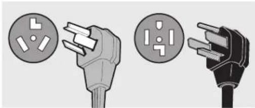
OUTLET RECEPTACLE - NEMA 10-30R or NEMA 14-30R receptacle to be located so the power supply cord is accessible when the dryer is in the installed position.
GROUNDING CONNECTION - See "Grounding requirements" in Electrical Installation section.
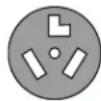
4-WIRE POWER SUPPLY CORD KIT (not supplied)
4-wire receptacle (NEMA type 14-30R)
The dryer MUST employ a 4-conductor power supply cord NEMA 14-30 type SRDT or ST (as required) rated at 240 volt AC minimum, 30
amp, with 4 open end spade lug connectors with upturned ends or closed loop connectors and marked for use with clothes dryers. For 4-wire cord connection instructions see ELECTRICAL CONNECTIONS FOR A 4-WIRE SYSTEM.

NOTE
Dryers manufactured for sale in Canada have factory-installed, 4-wire power supply cord (NEMA 14-30).
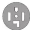
3-WIRE POWER SUPPLY CORD KIT (not supplied)
3-wire receptacle (NEMA type 10-30R)
The dryer MUST employ a 3-conductor power supply cord NEMA 10-30 type SRDT rated at 240 volt AC minimum, 30 amp, with 3 open end spade lug connectors with upturned ends or closed loop connectors and marked for use with clothes dryers. For 3-wire cord connection instructions see ELECTRICAL CONNECTIONS FOR A 3-WIRE SYSTEM.

WARNING
Improper grounding of the dryer may cause serious injury or death. Check with a licensed electrician if you are in doubt as to whether the appliance is properly grounded.
Manufactured or Mobile Home Installation
Installation MUST conform to current Manufactured Home Construction & Safety Standard, Title 24 CFR, Part 32-80 (formerly the Federal Standard for Mobile Home Construction and Safety, Title 24, HUD Part 280) or Standard CAN/CSAZ240 MH.
Clearance Requirements
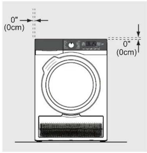
text_image
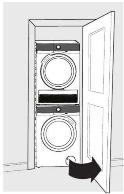
0" (0cm) 0" (0cm)Closet Installation
If installing the dryer in a closet, the closet door must remain open while the dryer is running to allow correct air circulation. See Use & Care Guide for more information.
natural_image
Diagram of a double door opening a washing machine with two wheels, showing the door closed and inside (no text or symbols)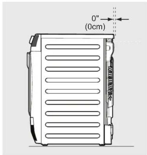
text_image
0" (0cm)
natural_image
Diagram of a double door with two doors open, showing front and back views of a washing machine (no text or symbols)| MINIMUM INSTALLATION CLEARANCES - Inches (cm) | ||||
| SIDES REAR | TOP FRONT | |||
| Alcove 0" (0 cm) 0" (0 cm) 0" (0 cm) n/a | ||||
| Under Counter 0" (0 cm) 0" (0 cm) 0" (0 cm) n/a | ||||
Dryer Dimensions
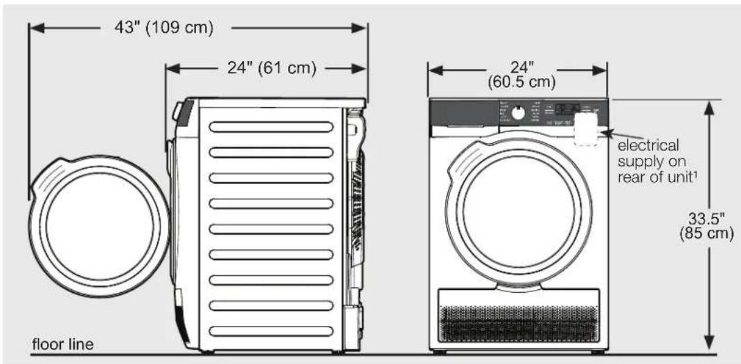
text_image
43" (109 cm) 24" (61 cm) floor line 24" (60.5 cm) electrical supply on rear of unit¹ 33.5" (85 cm)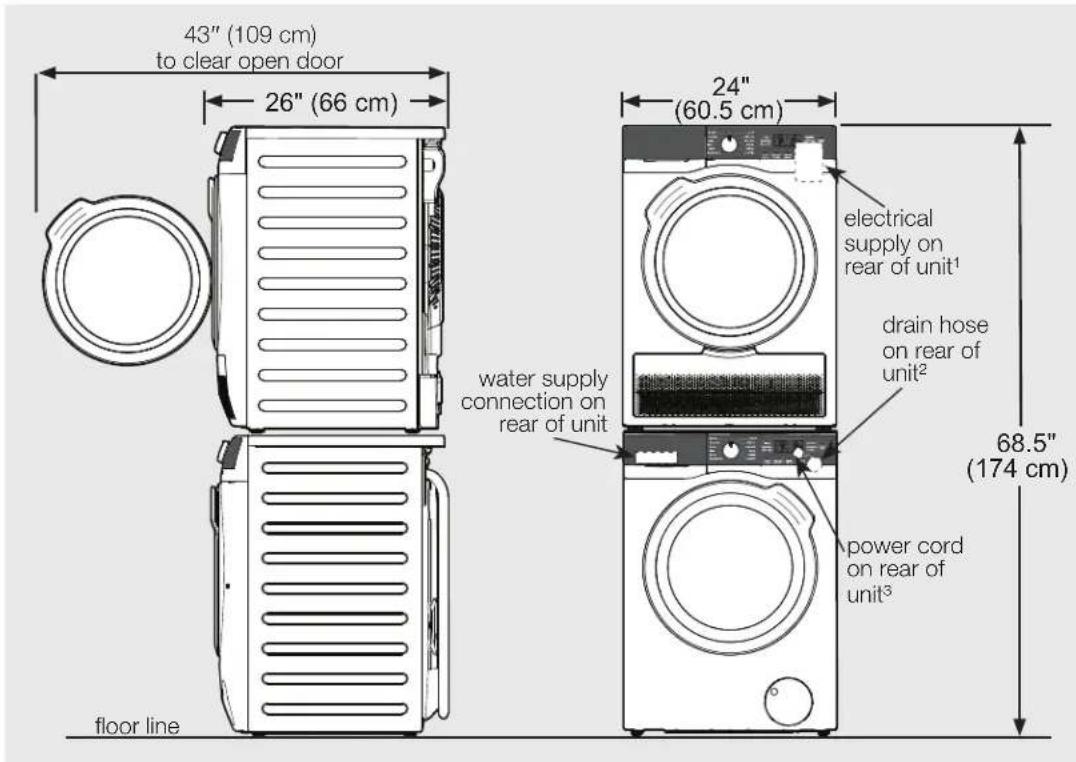
text_image
43" (109 cm) to clear open door 26" (66 cm) floor line 24" (60.5 cm) water supply connection on rear of unit electrical supply on rear of unit¹ drain hose on rear of unit² power cord on rear of unit³ 68.5" (174 cm)^1 Power supply cord length on Canadian dryer approximately 59 inches (150 cm).
^2 Drain hose length on washer approximately 55 inches (140 cm).
^3 Power supply cord length on washer approximately 59 inches (150 cm).
Electrical Installation
The following are specific requirements for proper and safe electrical installation of your dryer. Failure to follow these instructions can create electrical shock and/or a fire hazard.

WARNING
ELECTRICAL SHOCK HAZARD
- This appliance MUST be properly grounded. Electrical shock can result if the dryer is not properly grounded. Follow the instructions in this manual for proper grounding.
- Do not use an extension cord with this dryer. Some extension cords are not designed to withstand the amounts of electrical current this dryer utilizes and can melt, creating electrical shock and/or fire hazard. Locate the dryer within reach of the receptacle for the length power cord to be purchased, allowing some slack in the cord. Refer to the pre-installation requirements in this manual for the proper power cord to be purchased.

WARNING
ELECTRICAL SHOCK HAZARD
- A U.L.-approved strain relief must be installed onto power cord. If the strain relief is not attached, the cord can be pulled out of the dryer and can be cut by any movement of the cord, resulting in electrical shock.
- Do not use an aluminum wired receptacle with a copper wired power cord and plug (or vice versa). A chemical reaction occurs between copper and aluminum and can cause electrical shorts. The proper wiring and receptacle is a copper wired power cord with a copper wired receptacle.

NOTE
The electric dryer has been designed and certified to operate at both 240V and 208V. Drying times on a 208V power supply will, however, be approximately 20% longer than drying times on a 240V power supply. This is normal and expected behavior and applies to all drying cycles.

WARNING
ELECTRICAL SHOCK HAZARD
Improper connection of the equipment grounding conductor can result in a risk of electrical shock. Check with a licensed electrician if you are in doubt as to whether the appliance is properly grounded.
Grounding Requirements - Electric Dryer (USA)
For a grounded, cord-connected dryer:
- The dryer MUST be grounded. In the event of a malfunction or breakdown, grounding will reduce the risk of electrical shock by a path of least resistance for electrical current.
- After purchase and installation of a 3-wire or 4-wire power supply cord having an equipment-grounding conductor and a grounding plug matching the wiring system of the location of installation, the plug MUST be plugged into an appropriate, copper wired receptacle that is properly installed and grounded in accordance with all local codes and ordinances. If in doubt, call a licensed electrician.
- DO NOT modify the plug you've installed on this appliance. If it will not fit the outlet, have a proper outlet installed by a qualified electrician.
Grounding Requirements - Electric Dryer (Canada)
For a grounded, cord-connected dryer:
- The dryer MUST be grounded. In the event of a malfunction or breakdown, grounding will reduce the risk of electrical shock by a path of least resistance for electrical current.
- Since your dryer is equipped with a power supply cord having an equipment-grounding conductor and a grounding plug, the plug must be plugged into an appropriate outlet that is properly installed and grounded in accordance with all local codes and ordinances. If in doubt, call a licensed electrician.
- DO NOT modify the plug provided with this appliance. If it will not fit the outlet, have a proper outlet installed by a qualified electrician.
Electrical Connection (Non-Canada) - 3-wire Cord
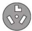
3-wire receptacle (NEMA type 10-30R)
text_image
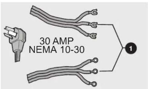
30 AMP NEMA 10-301 Neutral (center wire)

NOTE
Two cords shown above with different terminal types.

WARNING
ELECTRICAL SHOCK HAZARD
Failure to disconnect power source before servicing could result in personal injury or even death.
- Turn off power supply to outlet.
- Remove the three screws securing the terminal block access cover in the upper corner on the back of the dryer.

NOTE
Terminal screws were shipped from the factory temporarily attached inside the access cover.
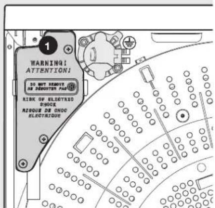
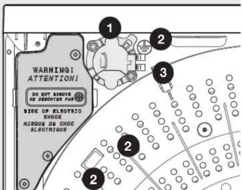
text_image
WARNING! ATTENTION! DO NOT REMAIN DE REQUATOR PAR RISK OF ELECTRIC ONOC AUXIQUE DE ONOC ELECTRAIQUE1 Terminal Block Access Cover
- Using an UNPLUGGED, UL-approved, 30 amp. power cord, NEMA 10-30 type SRDT, attach the neutral (center wire) conductor to the SILVER colored center terminal on the terminal block. Tighten the screw securely.

WARNING
ELECTRICAL SHOCK HAZARD
DO NOT move internal ground in a 3-wire system.
text_image
Diagram showing three connectors with labeled pins and connection points, likely illustrating a wiring or connector assembly.3 Neutral Silver Terminal
- Attach the remaining two power cord outer conductors to the outer, BRASS colored terminals on the terminal block. Tighten both screws securely.
text_image
Technical diagram showing three labeled electrical connectors with plus symbols and numbered callouts4 Outer Brass Terminals

WARNING
ELECTRICAL SHOCK HAZARD
Do not make a sharp bend or crimp wiring/conductor at connections.
- Reinstall the terminal block access cover.

WARNING
ELECTRICAL SHOCK HAZARD
Do not operate dryer without terminal cover in place. A correctly installed terminal block cover also acts a qualified strain relief for the power cord.

IMPORTANT
If moving dryer from a 4-wire system and installing it now in a 3-wire system, move the internal ground wire from the center terminal back to the GREEN screw under the terminal block.
Electrical Connection (Non-Canada) - 4-Wire Cord
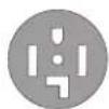
4-wire receptacle (NEMA type 14-30R)
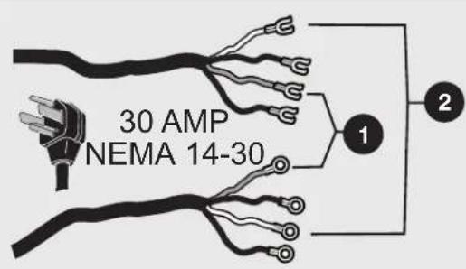
text_image
30 AMP NEMA 14-301 Ground GREEN wire
2 Neutral White wire

NOTE
Two cords shown above with different terminal types.

WARNING
ELECTRICAL SHOCK HAZARD
Failure to disconnect power source before servicing could result in personal injury or even death.
- Turn off power supply to outlet.
- Remove the three screws securing the terminal block access cover in the upper corner on the back of the dryer.

NOTE
Terminal screws were shipped from the factory temporarily attached inside the access cover.
text_image
WARNING! ATTENTION! DO NOT REMOVE RE DECONTEN PAR BISK OF ELECTRIC SHOCK RIQUE DE CHOC ELECTRIGUE1 Terminal block access cover
2 Access cover screw
DO NOT REMOVE - screw next to this text must not be removed.
- Disconnect the internal (WHITE) dryer harness wire from the (GREEN) ground screw next to the terminal block.
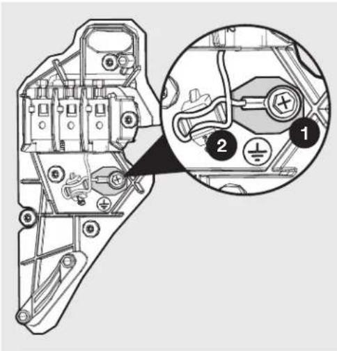
text_image
Technical diagram of a mechanical assembly with labeled parts and an inset magnified view showing tool connections.1 Internal ground (GREEN screw)
2 Internal dryer harness (WHITE wire)
- Using an UNPLUGGED, UL-approved, 30 amp. power cord, NEMA 14-30 type ST or SRDT, attach the ground (GREEN) power cord wire to the cabinet with the ground (GREEN) screw. Tighten the screw securely.
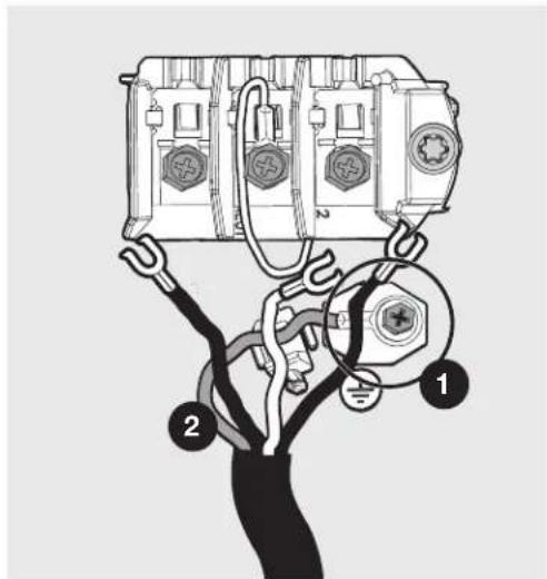
text_image
Diagram showing a person using a plug to connect two electrical components with labeled parts 1 and 21 Ground GREEN screw
2 GREEN ground wire
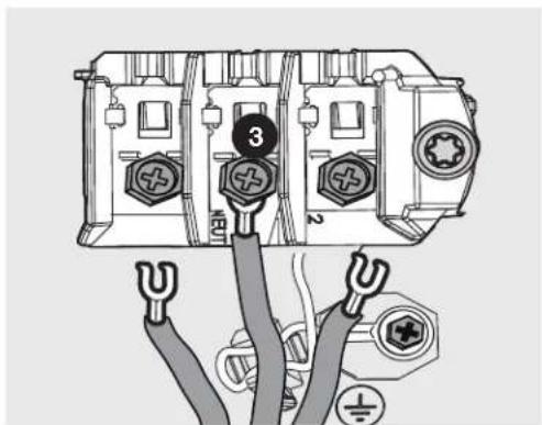
- Move the internal (WHITE) dryer harness wire to the terminal block and attach it along with the neutral (WHITE) power cord wire conductor to the center, SILVER colored terminal on the terminal block. Tighten the screw securely.
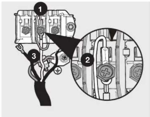
text_image
Diagram showing three labeled components of a car electrical switch, with magnified detail highlighting component 2 and component 3.1 Neutral silver terminal
2 Internal WHITE harness wire
3 WHITE neutral wire
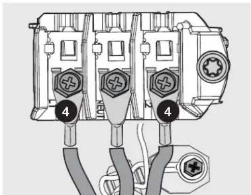
- Attach the RED and BLACK power cord conductors to the outer, BRASS colored terminals on the terminal block. Tighten both screws securely.
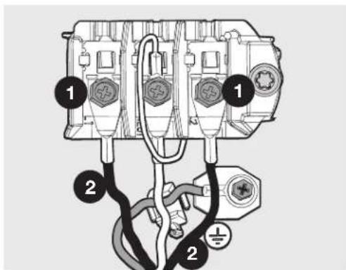
text_image
Diagram of an electrical connector with labeled parts and wiring connections1 Brass Terminal
2 BLACK or RED power wire
- Reinstall the terminal block access cover.

WARNING
ELECTRICAL SHOCK HAZARD
Do not make a sharp bend or crimp wiring/conductor at connections.

WARNING
ELECTRICAL SHOCK HAZARD
Do not operate dryer without terminal cover in place. A correctly installed terminal block cover also acts a qualified strain relief for the power cord.

NOTE
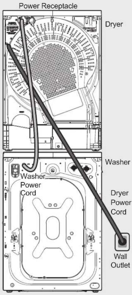
If you have an Electrolux compact dryer model number ELFE4222AW or ELFE422CAW, you may choose to power your Electrolux compact washer through it as shown. See illustrations.
text_image
Power Receptacle Dryer Washer Washer Power Cord Dryer Power Cord Wall Outlet
WARNING
NOT A GENERAL USE RECEPTACLE! Only for use with compatible Electrolux washer models listed in this Use & Care Guide. Keep the outlet closed if a compatible Electrolux washer plug is not connected to the dryer.
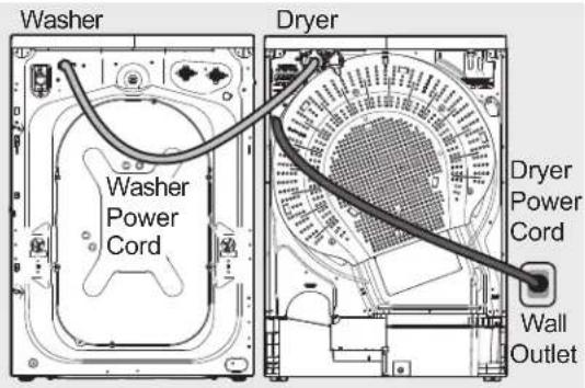
text_image
Washer Washer Power Cord Dryer Dryer Power Cord Wall OutletDirect Drain Kit (on some models)
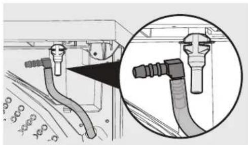
If your model included a direct drain kit, you may follow the instructions below to install it on your dryer for convenient drainage of your dryer's condensed water.
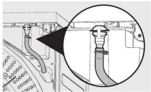
- Locate the red tubing and plastic fitting on the back of the dryer.
natural_image
Technical diagram showing a cable connector with a magnified inset view (no text or symbols)- With a pair of pliers, release the hose clamp and remove the tubing from the plastic fitting.
natural_image
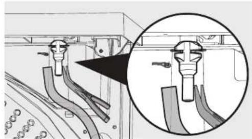
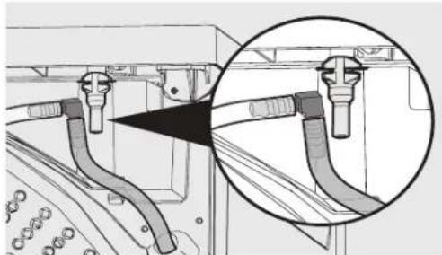
Technical illustration of a mechanical assembly with a magnified inset showing internal components (no text or symbols)- Retrieve the 90 degree plastic elbow from the direct drain installation kit that came with your dryer and install it onto the red tubing.
natural_image
Diagram showing pipe connections and a magnified inset of a mechanical component (no text or symbols)- Retrieve the clear tubing that came in the kit and install it also onto the elbow.
natural_image
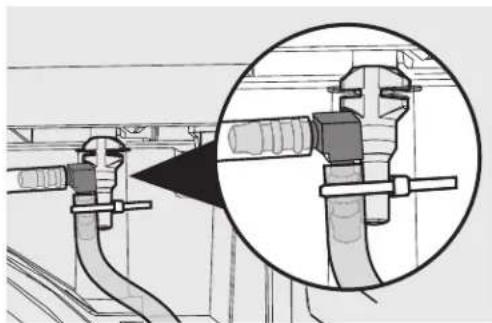
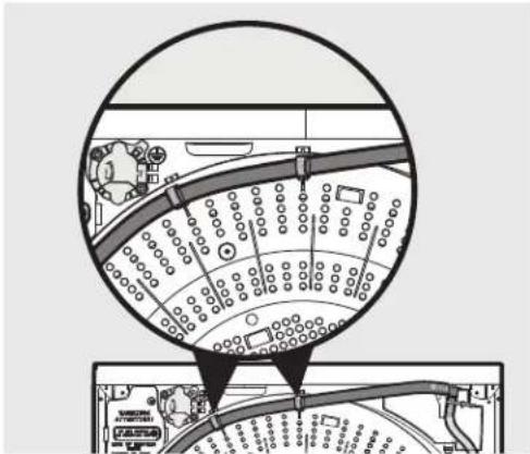
Technical diagram showing pipe fittings and a magnified inset of a mechanical component (no text or symbols)- With the plastic cable tie that came with the kit, secure the elbow and tubes to the plastic fitting.
natural_image
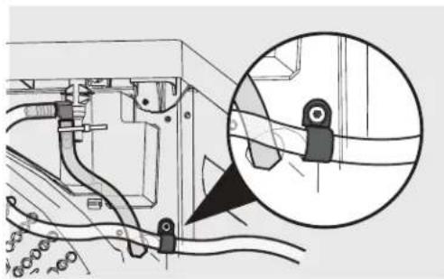
Technical illustration of pipe fittings and clamps in a factory setting, with an inset magnified view showing close-up details (no text or symbols)- To route the drain tube to the left of the dryer, secure the tube with the "P" clamp from the kit to the back of the dryer with the cabinet screw shown below.
natural_image
Technical diagram of a mechanical assembly with a magnified inset showing a detail (no text or symbols present)- To route the drain tube to the right of the dryer, route the tube across the back of the dryer and snap it into the "C" clips shown as below.
text_image
Diagram showing a circular layout with labeled circular elements and directional arrows, possibly representing a transportation or industrial system.- Install the hose hanger from the kit onto the end of the hose and insert in drain.
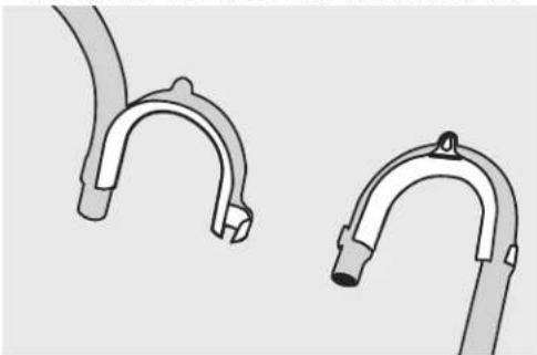
natural_image
Two mechanical clamp or bracket components with curved ends and connectors (no text or symbols visible)
IMPORTANT
Follow these guidelines for proper drain hose installation:
- The distance from the bottom of the drain tube sag to the top of highest part of drain tube should be no more than 20" (50 cm).
- Drain tube may need to be shortened with scissors if sag is greater than allowed.
- The drain height location should be no more than 40" (100 cm) above the bottom of the dryer feet.
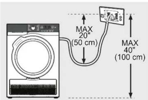
text_image
MAX 20" (50 cm) MAX 40" (100 cm)General Installation
- Use a carpenter's level to level your dryer front-to-back and side-to-side.
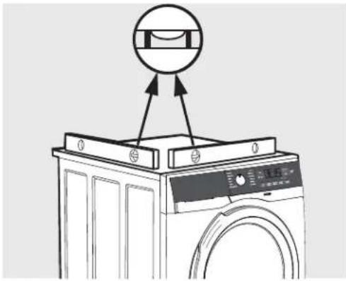
text_image
Diagram showing a washing machine with a circular component above it, indicating a mechanical or electrical component.- Use adjustable pliers or universal appliance wrench (See Accessories) to adjust the leveling legs so the dryer is level front-to-rear and side-to-side, and stable corner-to-corner.

natural_image
Illustration of a hand gripping a piece of material with a curved arrow indicating rotation (no text or symbols)- Press down on alternate corners and sides and feel for the slightest movement. Adjust the appropriate leg(s) so the dryer sits solidly on the floor on ALL four legs. Keep the leveling leg extension at a minimum for best performance of the dryer.
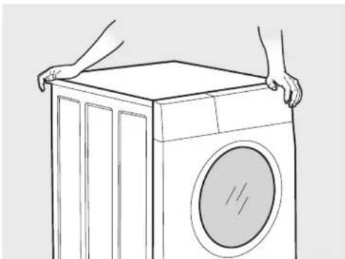
natural_image
Line drawing of hands holding a front-mounted washing machine (no text or symbols)
IMPORTANT
Be sure the power is off at a circuit breaker/fuse box before plugging the power cord into an outlet.
- Plug the power cord into a grounded outlet.
natural_image
Three different types of electrical plugs shown in grayscale, no text or symbols present- Turn on the power at the circuit breaker/fuse box.
- Read the Use & Care Guide provided with the dryer. It contains valuable and helpful information that will save you time and money.
- If you have any questions during initial operation, please review the "Avoid Service Checklist" in your Use & Care Guide before calling for service.
- Place these instructions in a location near the dryer for future reference.

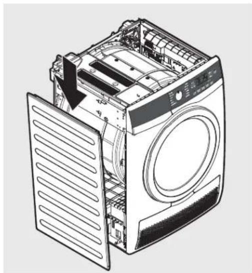
NOTE
A wiring diagram is located next to the water container behind the left cabinet panel.
natural_image
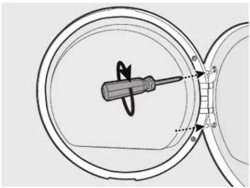
Technical line drawing of a washing machine showing internal components and a downward arrow indicating a component (no text or symbols present)- Locate a flat work surface, such as the top of the dryer or the floor near the dryer, and protect it with a soft cloth or towel.
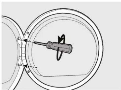
- Open the dryer door and remove the two hinge screws. Remove lower screw first, then upper screw.
natural_image
Technical diagram showing a screwdriver inserted into a circular component, with no visible text or symbols.- Gently place dryer door face down on flat, covered work surface.
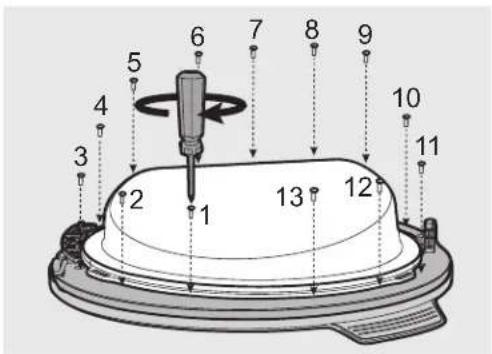
- Locate the 13 screws on the inner door ring. Remove and save these 13 screws.
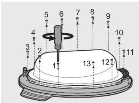
text_image
Technical diagram of a mechanical component with numbered parts and directional arrows indicating assembly or assembly steps.- Separate inner door ring from the rest of the door.
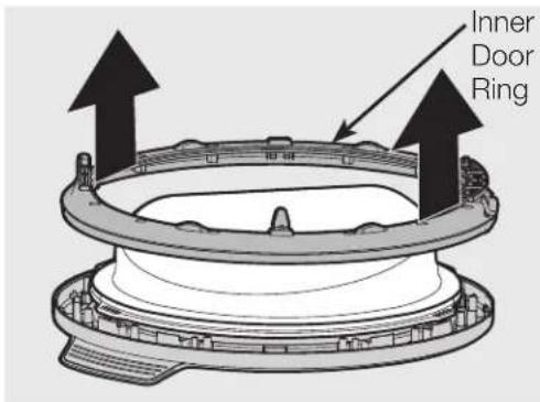
text_image
Inner Door Ring- Release the door switch striker by pulling on the two snap hooks located on the rear side of the inner door ring. Install the door switch striker on the opposite location (180 degrees from its original position in the inner door ring). Set the inner door ring aside.

natural_image
Diagram showing a gear or cam mechanism with an upward arrow and a small inset image of workers (no text or symbols)- Lift the inner lens and set it aside.
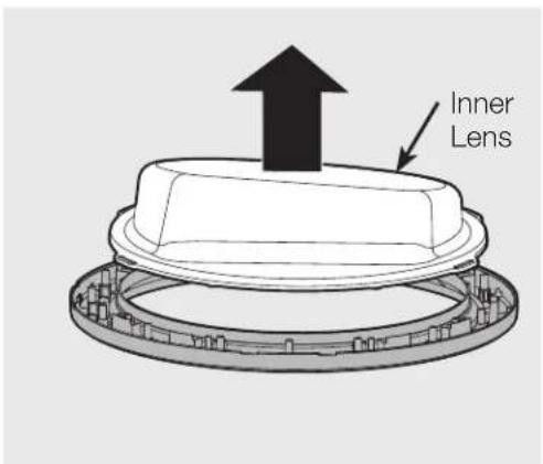
text_image
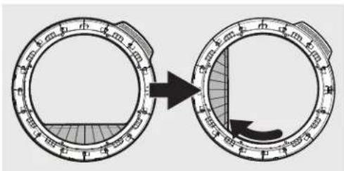
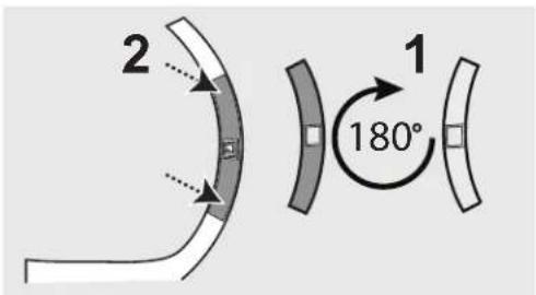
Inner Lens- Lift and rotate the semi-circular trim piece clockwise 90° from its original position and place onto the available plastic alignment features.
text_image
Diagram showing a circular device with measurement scale and directional arrow, likely illustrating a measurement or operation.- Rotate inner lens clockwise 90^ from its original position and place back into door assembly.
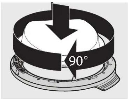
text_image
90°- Rotate the inner door ring counterclockwise 90^ from its original position and reattach with 13 screws removed earlier.
text_image
Technical diagram of a mechanical component with numbered parts and directional arrows indicating assembly or assembly steps.- Gently pry the plastic latch cover from the front panel and set it aside. Remove the 3 screws securing the door latch and release the latch.
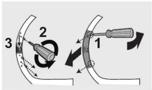
text_image
Diagram illustrating three-step tool manipulation process with labeled parts 1, 2, and 3- Rotate the latch 180^ and reinstall it in the opposite location with the 3 screws removed in previous step.
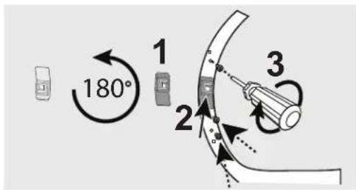
text_image
180° 1 2 3- Rotate the plastic latch cover 180^ and snap it in place around the door latch.
text_image
2 1 180°- While supporting the door, install the 2 hinge mounting screws removed in first step. Attach the upper screw first and then the lower one.
natural_image
Technical diagram of a screwdriver inside a circular housing, showing radial motion and alignment (no text or symbols)- Close the door and test operation of hinge, strike and latch.
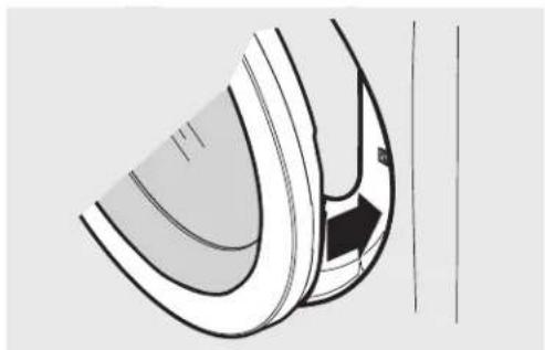
natural_image
Diagram of a curved mechanical component with a black arrow indicating a specific feature (no text or symbols present)DIRECT DRAIN KIT
P/N DK11
Depending on the model you purchased, a direct draining kit for your condensing dryer's water collection system may have been included in the initial purchase of your dryer. If your model did not include a direct draining kit, you may order one.
DRYER STACKING KIT
P/N STACKIT24
Depending on the model you purchased, a kit for stacking this dryer on top of matching washer may have been included in the initial purchase of your dryer. If your model did not include a stacking kit or you desire another stacking kit, you may order one.
UNIVERSAL APPLIANCE WRENCH
P/N 137019200
A UNIVERSAL APPLIANCE WRENCH is available to aid in dryer/washer feet adjustment.
Replacement Parts:
If replacements parts are needed for your washer, contact the source where you purchased your washer or refer to your Use & Care Guide for more information.

WARNING
ELECTRICAL SHOCK HAZARD
Label all wires prior to disconnection when servicing controls. Wiring errors can cause improper and dangerous operation. Verify proper operation after servicing.

CAUTION
Failure to use accessories manufactured by (or approved by) the manufacturer could result in personal injury, property damage or damage to the dryer.
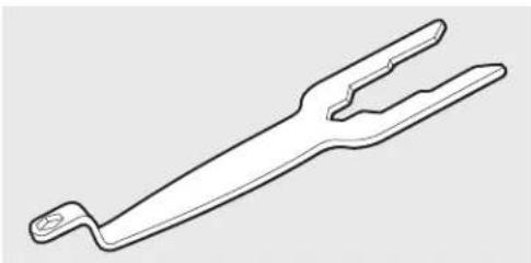
natural_image
Line drawing of a fork-like tool with two blades and a handle (no text or symbols)Universal Appliance Wrench
18 Notes

natural_image
Repeating pattern of gray geometric shapes on white background, no text or symbols presentEN FRONT LOAD DRYER
FR SÉCHEUSE À CHARGEMENT FRONTAL ES SECADORA DE CARGA FRONTAL
INSTALLATION INSTRUCTIONS
INSTRUCTIONS D'INSTALLATION
text_image
0" (0cm) 0" (0cm)natural_image
Diagram of a double door with two washing machines, one open and one closed, showing a black arrow indicating direction (no text or symbols)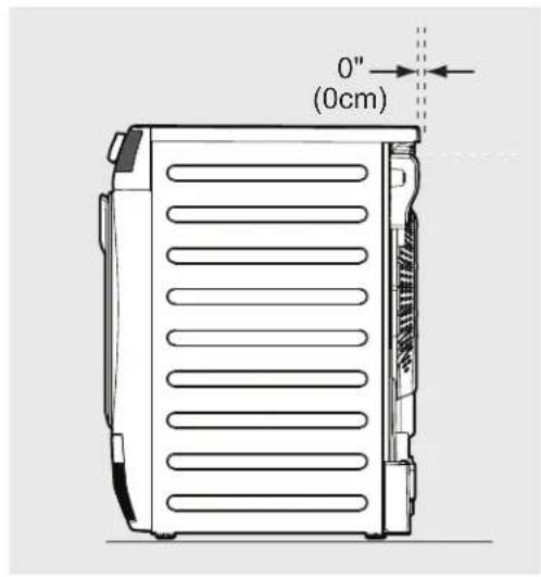
text_image
0" (0cm)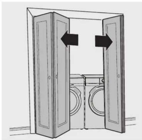
natural_image
Diagram of a double door with two doors open, showing front and back views of a washing machine (no text or symbols)| DÉGAGEMENTS MINIMUM POUR L'INSTALLATION | ||||
| CÔTÉS ARRIÈRE DESSUS DEVANT | ||||
| Alcôve 0 po (0 cm) 0 po (0 cm) 0 po (0 cm) s.o. | ||||
| Sous le comptoir 0 po (0 cm) 0 po (0 cm) 0 po (0 cm) s.o. | ||||
text_image
Diagram showing three connected electrical connectors with labeled pins and wiring connections, likely illustrating a power or signal routing setup.text_image
Technical diagram of a connector with four labeled pins (4) and connectors, likely for assembly or wiring instructions.text_image
30 AMP NEMA 14-30text_image
Technical diagram of a mechanical assembly with labeled parts and an inset magnified view showing component callouts.text_image
Diagram showing wiring connections between an electrical device with labeled parts 1 and 2text_image
Diagram showing three labeled parts of a vehicle engine component with magnified detail viewtext_image
Diagram of an electrical component with labeled parts, showing connections between terminals and wiring.natural_image
Technical diagram of a mechanical assembly with a magnified inset showing internal components (no text or symbols)natural_image
Technical line drawing of mechanical components with a magnified inset showing detail (no text or symbols)
AVERTISSEMENT
natural_image
Diagram showing a mechanical assembly with hoses and connectors, including a magnified inset of a connector detail (no text or symbols present)natural_image
Technical diagram showing pipe connections inside a vehicle or industrial enclosure, with an inset magnified view of the pipe assembly (no text or symbols present)natural_image
Technical line drawing of two pipe fittings with a magnified inset showing internal components (no text or symbols)natural_image
Technical diagram of a mechanical assembly with a magnified inset showing a detail of a component (no text or symbols present)natural_image
Diagram of a vehicle dashboard with circular layout and labeled components, no readable text or symbols present.natural_image
Two mechanical clamp or bracket components with curved ends and connectors (no text or symbols visible)
IMPORTANT
text_image
MAX 20" (50 cm) MAX 40" (100 cm)text_image
Diagram showing a washing machine with labeled components and a circular component above it, likely illustrating a washing or cleaning process.natural_image
Illustration of a hand gripping a piece of paper with a curved arrow indicating rotation (no text or symbols)natural_image
Line drawing of hands holding a front-mounted washing machine (no text or symbols)
IMPORTANT
natural_image
Illustration of three different types of electrical plugs: two with circuit symbols and one with a plug, shown without any text or labels.natural_image
Technical line drawing of a washing machine with open lid and ventilation slots (no text or symbols)natural_image
Technical diagram of a screwdriver inserted into a circular component, showing internal structure and alignment (no text or symbols)text_image
Diagram of a mechanical device with numbered components, likely a tool or assembly stepnatural_image
Diagram showing a gear mechanism with an upward arrow and gear teeth, no text or symbols presenttext_image
Diagram showing a circular dial with measurement markings and an arrow indicating direction, likely illustrating a measurement or calibration process.text_image
Labeled diagram of a mechanical component with numbered parts and directional arrows indicating assembly or assembly steps.natural_image
Technical diagram of a screwdriver inside a circular housing, showing internal components and alignment indicators (no text or symbols)natural_image
Pure technical line drawing of a curved mechanical component without any text, numbers, or symbolsnatural_image
Line drawing of a fork-like tool with two blades and a handle (no text or symbols)natural_image
Repeating pattern of gray geometric shapes on white background, no text or symbols presentEN FRONT LOAD DRYER
FR SÉCHEUSE Á CHARGEMENT FRONTAL
ES SECADORA DE CARGA FRONTAL
INSTALLATION INSTRUCTIONS
INSTRUCTIONS D'INSTALLATION
natural_image
Diagram of a double door with two circular washers inside, showing a black arrow pointing to the door (no text or symbols)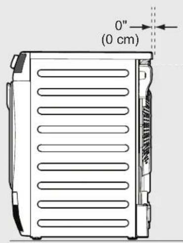
text_image
0" (0 cm)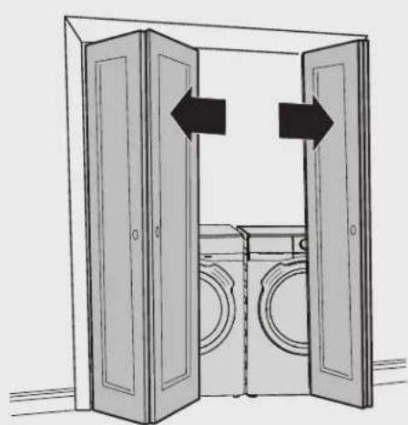
natural_image
Diagram of a double door with open doors and laundry units, showing bidirectional arrows indicating movement (no text or symbols)1 Neutro (cable central)

NOTA
text_image
Diagram showing connections between electrical connectors with numbered labels and symbols3 Terminal plateado neutro
text_image
Technical diagram of a connector with labeled pins and connectors, showing wiring connections and mounting points.4 Terminales exteriores de cobre

ADVERTENCIA
RIESGO DE DESCARGA ELÉCTRICA
text_image
30 AMP NEMA 14-301 Cable VERDE de masa
2 Cable blanco neutro

NOTA
text_image
Technical diagram of a mechanical device with labeled components and an inset magnified view showing internal wiring connections.1 Masa interna (tornillo VERDE)
2 Mazo de cables interno de la secadora (cable BLANCO)
text_image
Diagram showing wiring connections between an electrical device with labeled parts 1 and 21 Tornillo VERDE de masa
2 Cable VERDE de masa
text_image
Diagram showing three labeled components of a device with an arrow pointing to a plug, and a magnified inset illustrating the internal wiring.1 Terminal plateado neutro
2 Mazo de cables BLANCO interno
3 Cable BLANCO neutro
text_image
Diagram of an electrical connector with labeled parts and wiring connectionsnatural_image
Technical diagram showing a mechanical assembly with attached tubing and a magnified inset (no text or symbols)natural_image
Technical illustration of a mechanical component with a magnified inset showing internal structure (no text or symbols)natural_image
Diagram showing hoses connected to a vehicle, with an inset close-up of the hose assembly (no text or labels)natural_image
Technical diagram showing pipe connections inside a vehicle chassis, with an inset magnified view of the cable assembly (no text or labels)natural_image
Technical line drawing of a pipe connection with a magnified inset showing internal components (no text or symbols)natural_image
Technical diagram of a mechanical assembly with a magnified inset showing a detail of a component (no text or symbols present)text_image
Diagram showing aircraft cockpit layout with labeled components and directional arrows, likely illustrating aircraft design or navigation.natural_image
Two types of U-shaped metal pipe fittings or clips, shown in grayscale without any text or symbols.
IMPORTANTE
text_image
MAX 20" (50 cm) MAX 40" (100 cm)Instalación general
text_image
Diagram showing a washing machine with labeled components and a circular component above it, likely illustrating a washing or laundry system.natural_image
Illustration of a hand gripping a vertical object with an arrow indicating rotational motion (no text or symbols)natural_image
Line drawing of hands holding a front-mounted washing machine (no text or symbols)
IMPORTANTE
natural_image
Three different types of electrical plugs shown in grayscale, no text or symbols presentnatural_image
Technical line drawing of a washing machine with open lid and internal components (no text or symbols)natural_image
Technical diagram showing a screwdriver inserted into a circular component, with no visible text or symbols.text_image
Technical diagram of a mechanical component with numbered parts and directional arrows indicating assembly or assembly steps.natural_image
Diagram showing a gear or cam mechanism with an upward arrow and a circular inset view of the gear (no text or symbols)text_image
Lente interiortext_image
Diagram showing a circular device with measurement scale and directional arrow, likely illustrating a measurement or operation.text_image
Labeled diagram of a mechanical device with numbered components and a central tool or screwdriver.natural_image
Technical diagram of a mechanical component with concentric circles and a central screwdriver (no text or symbols)natural_image
Diagram of a curved mechanical component with internal channels and an arrow indicating direction (no text or symbols)KIT DE DESAGÜE DIRECTO
N° de pieza DK11
natural_image
Line drawing of a fork-like tool with two blades and a handle (no text or symbols)Llave de aparato universal
18 Notas