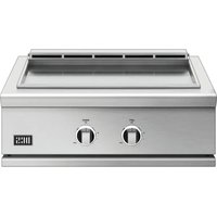
GDE1-30 - Barbecue DCS - Free user manual and instructions
Find the device manual for free GDE1-30 DCS in PDF.


User questions about GDE1-30 DCS
0 question about this device. Answer the ones you know or ask your own.
Ask a new question about this device
Download the instructions for your Barbecue in PDF format for free! Find your manual GDE1-30 - DCS and take your electronic device back in hand. On this page are published all the documents necessary for the use of your device. GDE1-30 by DCS.
USER MANUAL GDE1-30 DCS
- Shut off gas to the appliance.
- Extinguish any open flame.
- Open lid.
- If odor continues, keep away from the appliance and immediately call your gas supplier or your fire department.
WARNING
- Do not store or use gasoline or other flammable liquids or vapors in the vicinity of this or any other appliance.
- An LP cylinder not connected for use must not be stored in the vicinity of this or any other appliance.
WARNING!
Electric Shock Hazard
Failure to follow this advice may result in electric shock or death.
- This appliance is equipped with a three-prong or four-prong grounding plug for your protection against shock hazard and should be plugged directly into a properly grounded power outlet.
- Never remove the grounding plug or use with a 2 prong adapter.
- Use only extension cords with a 3 prong grounding plug, rated for the power of the equipment, and approved for outdoor use with a W-A marking.
- Do not immerse cord or plugs in water or other liquid.
WARNING!

Fire Hazard
Failure to follow this advice may result in a fire causing death or serious injury.
- This unit is for outdoor use only. Do not operate the side burner/griddle under un protected combustible construction. Do not use in buildings, garages, sheds, breezeways, covered structures or other such enclosed areas.
- Never store a spare LP cylinder under or near this unit. Do not fill the gas tank more than 80% of its total capacity.
- Do not use aluminium foil to line drip pans. This can interfere with combustion, air flow or trap excessive heat in the control area. The result of this can be melted dials or damaged ignition components.
WARNING!

Hot Surface Hazard
Failure to follow this advice may result in fire, burns, scars or personal injury.
- Accessible parts may become hot during use.
- When in use, do not touch the burner, grate, or immediate surrounding area as these areas become extremely hot. Clean the with caution.
- Never let clothing or other flammable materials come in contact with or get too close to any grate, burner or hot surface until it has cooled.
- Never lean over an open unit. When lighting a burner, always pay close attention to what you are doing. Be certain you are pushing the burner dial when you attempt to light.
- Never operate the unit without a drip tray. Let hot grease cool before attempting to handle it. Avoid letting grease deposits collect in the drip pan.
- Ensure all controls are turned off and the unit is cool before using any type of aerosol cleaner on or around the product. The chemical that produces the spraying action could, in the presence of heat, ignite or cause metal to corrode
- Keep any electrical supply cord and the fuel supply hose away from any heated surfaces.
WARNING!

Excessive weight Hazard
Failure to follow this advice may result in personal injury.
- Two or more persons are required to move and install this unit or to handle the griddle plate.
WARNING!

Explosion Hazard
Failure to follow this advice may result in injury or death
If you smell gas, do not use the appliance.
- Do not use water on grease fires, a violent steam explosion may result. Turn all burners off, then smother fire or flame or use dry chemical or foam-type extinguisher.
- Do not heat unopened food containers such as cans - build up of pressure may cause container to burst and result in injury.
WARNING!
To reduce the risk of fire, injury to persons or damage when using the appliance, follow the important safety instructions listed below. Read all the guidance before using the appliance. Do not use an outdoor cooking gas appliance for purposes other than Intended.
Servicing
- Do not repair or replace any part of the appliance unless specifically recommended in the user guide. All other servicing should be undertaken by a Fisher & Paykel trained and supported service technician or qualified person.
- Only use the product with the type of gas specified on the rating plate. To change gas type a factory conversion kit is required.
Fire Hazard
- Use only in well ventilated areas.
- Never leave the product unattended when in use.
- Always remove the cover before lighting. Do not replace cover during cooking or before appliance has cooled.
- Do not use a flame to check for gas leaks.
- Do not attempt to disconnect any gas connections while your appliance is in use or the gas supply is on.
- Never connect an unregulated gas line to the appliance.
- Have an ABC rated Fire Extinguisher accessible - never attempt to extinguish a grease fire with water or other liquids.
Storage
- When not in use, ensure the gas supply is turned off at the supply cylinder.
- Keep appliance covered when not in
Storage of the appliance indoors is permissible only if the cylinder is disconnected and removed from the unit. - Cylinders must be stored outdoors, out of reach of children and must not be stored in a building, garage, or any other enclosed area.
SAFETY AND WARNINGS
- Do not store a full LP tank in direct sunlight.
- After a period of storage or non-use, the appliance should be checked for gas leaks, deterioration, proper assembly, and burner obstructions before use.
General Use
- This appliance is not intended to be installed in or on recreational vehicles, trailers or boats.
After lighting burners, ensure they are operating correctly. - When using the appliance, be sure that all parts of the unit are firmly in place and that everything is stable.
- On cart mounted units, never move without first allowing the appliance to cool, disconnecting the cable and ensuring that the gas supply is turned off.
- Do not move the appliance during use
Children should not be left alone or unattended in an area where the product is being used. Never allow them to sit, stand or play on or around the unit at any time. - Do not store items of interest to children around or below the appliance.
- Never use the appliance in a windy area.
- To put out flare-ups, adjust the controls to lower the temperature.
- Do not obstruct the flow of combustion and ventilation to the appliance.
- Spiders and insects can nest in the burners or openings and can block or restrict the burner. This can cause a flash back to the control panel which can cause a fire.
- Do not try lighting this appliance without reading the lighting instruction in the user guide.
- Do not locate, store or operate the appliance on a slope.
- This product must be installed by a licensed plumber or gas fitter when Installed within the Commonwealth of Massachusetts.
- Do not fill the gas tank more than 80% of its total capacity.
- Never use a dented or rusty LP tank. Keep the ventilation openings of the cylinder enclosure free and clear from debris.
- Clean and perform general maintenance on the appliance regularly. Watch for corrosion, cracks, or Insect activity. Check the regulator, hoses, burner ports, air shutter, and venturi/valve section carefully. Always turn off gas at the source prior to inspecting.
- You must inspect the unit at least once a year or immediately if the smell of gas is present in conjunction with the burner flames appearing yellow, the appliance does not reach temperature or heats unevenly or the unit makes popping noises.
- Do not smoke while leak testing and extinguish all open flames.
- When cleaning the burners centre the burner onto the orifice correctly and ensure they are level before lighting to prevent fire hazard or explosion. Refer to the user guide for detailed guidance.
- Use only a Ground Fault Interruption (GFI) protected circuit with this outdoor cooking gas appliance.
- Unplug from the outlet when not in use and before cleaning. Allow to cool before putting on or taking off parts.
- Do not operate the appliance with a damaged cord, plug, or after the appliance malfunctions or has been damaged in any manner. Contact the manufacturer for repair.
- Do not let the cord hang over the edge of a table or touch hot surfaces.
- When connecting, first connect plug to the appliance then plug appliance into the outlet.
- Do not place the unit directly on the ground or other surface without support. This will prevent damage to the regulator/hose assembly.
Gas requirements
Designed for use with a Type 1 system only.
- Constructed and marked in accordance with the Specifications for LP gas Cylinders of the U.S. Department of Transportation (D.O.T.) or the Standard for Cylinders, Spheres and Tubes for Transportation of Dangerous Goods and Commission, CAN/ CSA-B339
Provided with a listed overfilling prevention device.
- Provided with a cylinder connection device compatible with the connection for outdoor cooking gas appliances
- This appliance can be used with any brand of 20lb LP gas tank provided it is compatible with a proper retention device (not supplied).
The LP gas cylinder must be: - The cylinder must be provided with a shut-off valve terminating in an LP gas supply cylinder valve outlet specified, as applicable, for connection Type 1.
- Do not change the regulator/hose assembly from that supplied with the unit or attempt to use a Type 1 equipped regulator/hose assembly with a standard 510 POL tank/valve assembly.
- Never use a cylinder with a damaged valve. The cylinder that is used must have a collar to protect the cylinder valve.
An installer-supplied gas shut-off valve must be installed in an easily accessible location - All installer supplied parts must conform to local codes, or in the absence of local codes, with the National Electrical Code, ANSI/NFPA 70 or the Canadian Electrical Code, CSA C22.1, and the National Fuel Gas Code, ANSI Z223.1 or CSA-B149.1 Natural Gas Installation Code or CSA-B149.2 Propane Installation Code.
- In Massachusetts such shut-off valves should be approved by the Board of State Examiners or Plumbers & Gas Filters.
- All pipe sealants must be an ap proved type and resistant to the actions of LP gases. Never use pipe sealant on flare fittings.
- A dented or rusty LP tank may be hazardous and should be checked by your LP supplier.
Always check for leaks after every LP tank change.
For LP units, check for leaks with a full cylinder. - Do not use the appliance until all connections have been checked and do not leak.
- Before each use, inspect the gas supply piping or hose prior to turning the gas ON. If there is evidence of cuts, wear, or abrasion, it must be replaced prior to use. The pressure regulator and hose assembly supplied with the unit must be used. If replacements are needed, contact customer care at www.dcsappliances.com
SAVE THESE INSTRUCTIONS
The models shown in this Installation guide may not be available in all markets and are subject to change at any time. For current details about model and specification availability in your country, please visit our website dcappolances.com or contact: your local DCS dealer.
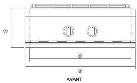
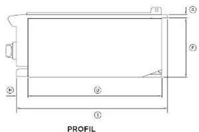
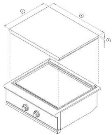
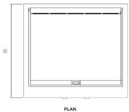
PRODUCT DIMENSIONS
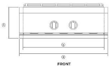
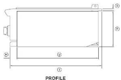
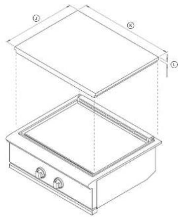
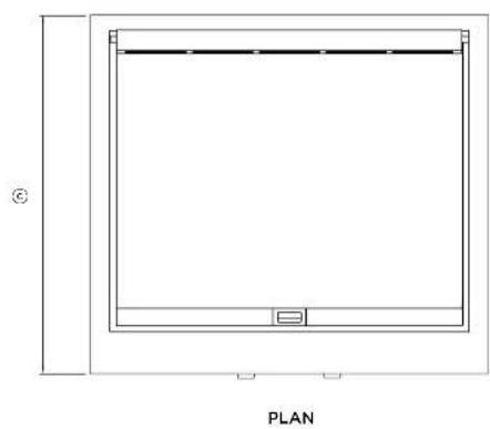
| PRODUCT DIMENSIONS | GDE1 MODELS | |
| INCHES MM | ||
| A Overall height (excluding burners and pan supports) | 10 1/2 | 266 |
| B Overall width 30 762 | ||
| C Overall depth (excluding dials) 26 7/8 683 | ||
| D Depth of chassis 22 1/2 572 | ||
| E Width of chassis (including bracket) 27 13/16 707 | ||
| F Height below countertop 10 1/8 257 | ||
| G Height of surface above countertop | 9/16 | 14 |
| H Depth of control panel to front of chassis | 2 3/16 | 56 |
| I Depth from control panel to rear of product | 25 1/2 | 647 |
| J Depth of lid | 22 15/16 583 | |
| K Width of lid | 29 1/2 | 750 |
| L Height of lid | 29 1/2 | 43 |
CUTOUT DIMENSIONS
STANDARD CUTOUT INSULATED JACKET CUTOUT
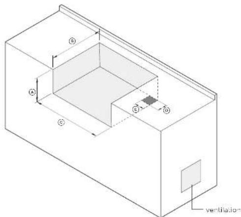
| CUTOUT DIMENSIONS | GDE1-30 MODELS | |
| INCHES MM | ||
| Height of cutout | 10 1/8 | 257 |
| Depth of cutout | 22 3/4 | 578 |
| Width of cutout | 28 1/2 | 724 |
| Depth of gas supply opening 4 102 | ||
| Width of gas supply opening 4 15/16 125 | ||
Notes:
- When determining a suitable location, take into account uncertainties such as exposure to wind proximity to traffic paths, and keeping any gas supply lines as short as possible.
The counter and supporting judges or dexs must be level and flat.
The enclosure would have ventilation holes to prevent gas buildup in the vessel of a leak. Refer to ANSI 72158.
Standards for Boiler Cooking Gas Appliances, Section 1.7 Requirements For Self-Centered - Gas Supply Systems.
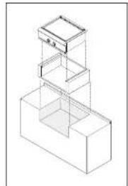
If the unit is to be placed into a combustible enclosure, an insulated jacket is required.
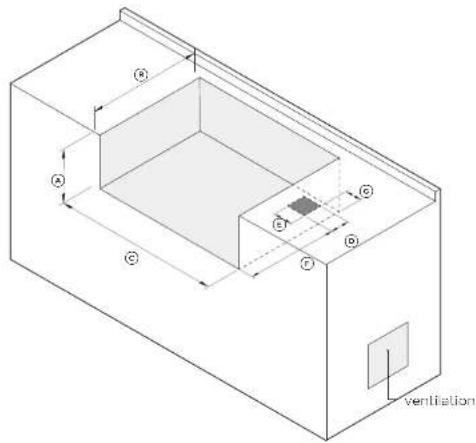
| CUTOUT DIMENSIONS | GDE1-30 MODELS | |
| INCHES MM | ||
| Height of cutout | 11 1/8 | 283 |
| Depth of cutout | 23 3/4 | 603 |
| Width of cutout | 34 7/8 | 886 |
| Depth of gas supply opening 4 102 | ||
| Width of gas supply opening 4 102 | ||
| Depth to gas supply opening from front of cutout | 18 1/2 | 470 |
| Width to gas supply opening from side of cutout | 3 1/2 | 89 |
Notes:
Use only the DCS Integrated Jacket which has specifically item designed and tested for this purpose. To purchase access covers and showers, visit occapoplascom.com
30"access doors model number:ADN130
30" access drawers model number: ADR2-30
BUILT-IN CLEARANCES
Clearances to non-combustible construction
Material which is not capable of being ignited and burned, such as materials consisting entirely of, or a combination of, steel, iron, brick, tile, concrete, slate, and plaster.
The griddle is designed for easy placement into built-in masonry enclosures. For non-combustible applications the unit drops into the opening and hangs from its side flanges. A deck is not required to support it from the bottom.
Fisher & Paykel recommends installing the manual shut-off valve in a location readily accessible by the customer, so that gas to the appliance can be shut off in an emergency situation. However, the appliance must not be modified in any way to accommodate such placement.
A level should be used to ensure that the unit is level both front-to-back and side-to-side. If it is not level, burner combustion may be erratic or the unit may not function efficiently for grease flow.
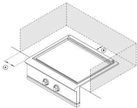
| CLEARANCE DIMENSIONS | GDE1-30 MODELS |
| INCHES MM | |
| Minimum distance from non-combustible construction to rear of griddle (above counter) | 3 76 |
| Minimum distance from non-combustible construction to sides of griddle (above counter) | 6 152 |
BUILT-IN CLEARANCES
Clearances to combustible construction
Any materials of a building structure or decorative structure made of wood, compressed paper, plant fibres, vinyl/plastic or other materials that are capable of transferring heat or being ignited and burned. Such material shall be considered combustible even though flame-proofed, fire-retardant treated or surface-painted, or plastered.
Do not use this appliance under unprotected overhead combustible surfaces.
Insulated jacket
If the griddle is to be placed into a combustible enclosure, an approved insulated jacket is necessary. Insulated jackets are available from your dealer. Use only the DCS insulated jacket which has specifically been designed and tested for this purpose. Review the detail drawing shown and take into account the provisions shown for gas line connection clearance in the right rear corner. It is required that ventilation holes are provided in the enclosure to eliminate the potential build-up of gas in the event of a gas leak. The supporting ledges or deck must be level and flat and strong enough to support the grill and insulated jacket. The counter should also be level.
30" Insulated Jacket part number: 70859
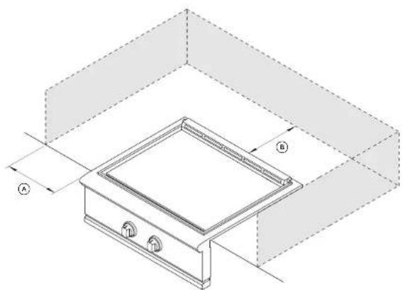
| CLEARANCE DIMENSIONS | GDE1-30 MODELS |
| INCHES MM | |
| Minimum distance from combustible construction to rear of griddle (above counter) | 12 305 |
| Minimum distance from combustible construction to sides of griddle (above counter) | 12 305 |
GRIDDLE PLATE

Excessive weight hazard
Two or more persons are required to handle the griddle plate.
Ensure the griddle plate is removed before moving the product to the installation location.
Removing the griddle plate
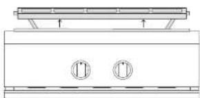
①
Remove the vent assembly by pulling up gently from the product, and set aside on a protected surface.
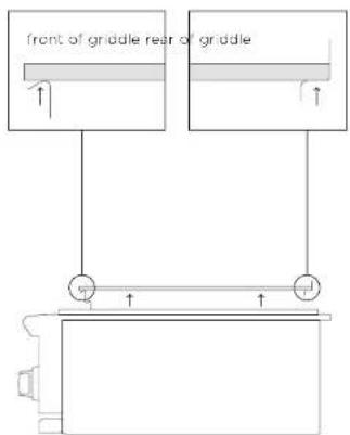
②
Grip the griddle plate from under the brackets at the front and rear of the product as shown.
lift up the griddle assembly and set aside on a protected surface.
Replacing the griddle plate
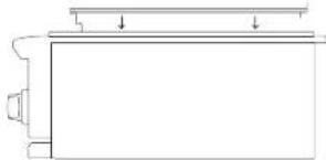
(1)
Grip the front and rear of the plate. Lower the plate to slot back in place onto the product ensuring it is centered.
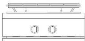
2
Replace the vent assembly by slotting the flash tubes back gently into the support brackets and lowering.
ELECTRICAL CONNECTION
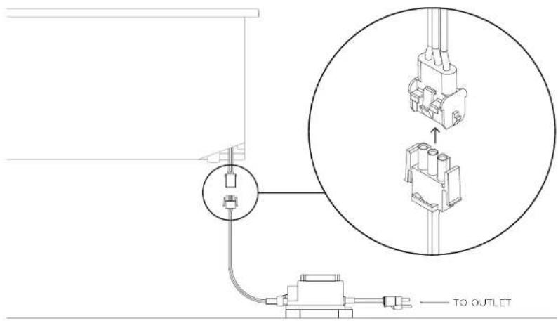
All units are supplied with a 12V power transformer to operate the products ignition and dial illumination features. The transformer is sealed in a box with an attached power supply cord.
Electrical requirements
Use only a Ground Fault Interruption (GFI) protected circuit with this product.
An outdoor 120VAC 15A GFI electrical outlet should be installed by a qualified electrician either inside the island enclosure for built-in units, or near the location where a free-standing unit will be used. For built-in products, the supplied 12V transformer should be connected during installation.
Installation
The transformer must be secured below the product in a dry location away from any excessive heat. Be sure to provide adequate access to facilitate service if the transformer or connections require maintenance.
Dial halos
When a dial is in use, an orange halo around that dial will illuminate. This will change from orange to white if the dial is turned off but another dial remains active. If all dials are turned OFF, all halos will dim.
Multiple DCS Series 9 products may be linked together to allow for cross-product halo illumination. To allow for this functionality, an approved DCS kit is required and can be purchased separately from your local DCS dealer.
If the ignition or dial halos fail to operate, a connection may have come loose during installation or the GFI may have tripped requiring a reset. Refer to the troubleshooting section of your user guide for further guidance.
GAS CONNECTION
GAS REQUIREMENTS NATURAL GAS CONNECTION
Verify the type of gas supply to be used, either natural or LP, and make sure the marking on the appliance rating plate agrees with that of the supply. The rating plate is located on the underside of the drip tray. Never connect an unregulated gas line to the appliance. You must use a gas regulator even if the supply is controlled.
Gas conversion kits are available from Customer Care. When ordering gas conversion kits, have the model number, and the type of gas (natural or LP) from your griddle.
The appliance and its individual shut-off valve must be disconnected from the gas supply piping system during any pressure testing of that system at test pressures in excess of 1/2 PSIG (3.5 kPa.) The appliance must be isolated from the gas supply piping system by closing its individual manual shut-off valve during any pressure testing of the gas supply piping system at test pressures equal to or less than 1/2 PSIG (3.5 kPa.).
Total gas consumption of the griddle with all burners on HI
GDE1:40,000 Btu/hr
Note:
- If it is evident there is excessive abrasion or wear, or the hose is cut, it must be replaced prior to the outdoor cooking gas appliance being put into operation.
The replacement hose assembly shall be that specified by the manufacturer.
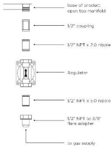
Connection: 1 / 2^ NPT male with 3 / 8'' flare adaptor Operating pressure: 4.0'' W.C. Supply pressure: 5'' to 14'' W.C. If in excess of 14'' W.C. a step down regulator is required. Check with your local gas utility company or local codes for instructions on installing gas supply lines. Be sure to check on type and size of run, and how deep to bury the line. If the gas line is too small, the gridle will not function properly. Any joint sealant used must be an approved type and be resistive to the actions of LP gases.
Connecting the fittings supplied with the griddle
Use joint compound on male threads only. Do not use joint compound on the flare end of the 1/2 NPT to 3/8 flare adapter. Ensure that the regulator arrow points in the direction of gas flow towards the unit, away from the supply. Do not forget to place the installer-supplied gas valve in an accessible location.
CART LP CONNECTION
Units set for use with LP gas come equipped with a high capacity hose/regulator assembly for connection to a standard 20 lb. LP cylinder (Type 1). The LP tank is not included. The grill system is leak tested, do not remove the Regulator/Hose assembly from the product during cart installation.
Connection: LP Hose with a type 1 quick disconnect and regulator. Operating pressure: 11.0^ .C
Connecting LP regulator/hose assembly to the tank/valve assembly
First, ensure the main valve on the tank is completely closed, all burner dials are in the OFF position and the cart is stable. Although the flow of gas is stopped when the Type 1 system is disconnected as part of its safety feature, you should always turn off the LP tank main valve after each use and during transport of the tank or unit.
Open the tank drawer of the cart and place the LP tank into the tank retention device (as shown in the cart installation guide). Insert the regulator inlet into the tank valve and turn the black coupler clockwise until it tightens. Do not over tighten the coupler. Turn the main tank valve ON and the burner control valves to HI for about 20 seconds to allow the air in the system to purge. Turn valves OFF and wait 5 minutes before attempting to ignite the burners.
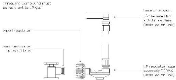
Changing the LP cylinder
Ensure the main tank valve is turned off before turning the coupler counter clockwise, the inlet will then disengage. Remove the inlet from the tank valve opening. Your local LP filling station should be equipped with the proper equipment to fill your tank.
Do not attempt to remove, repair or replace the regulator/hose assembly. This must be done by qualified and licensed technician only.
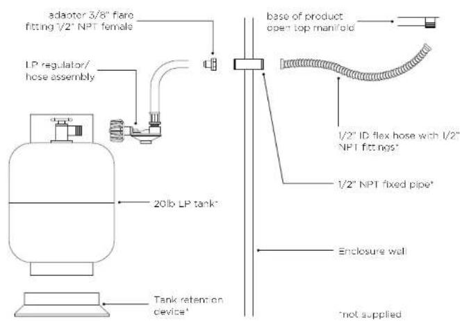
BUILT-IN LP CONNECTION
If the grill is to be installed in a built-in application, then the grill must be installed in accordance with the built-in installation guidelines and the LP regulator/hose assembly must be removed from the product.
When an LP unit is being directly connected to an LP house system, you must follow the natural gas connection guidelines. The installer must provide the proper gas regulator to reduce the gas pressure to 11^ W.C.
Connection: LP Hose with a Type 1 quick disconnect and regulator. Operating pressure: 11.0" W.C. To operate your built-in grill on LP gas utilizing a 20lb type 1 cylinder, then a built-in LP tank restraint must be installed prior to initial use of the grill. The Installer must supply 12 " ID Flex hose and fixed pipe and a flare adaptor
LEAK TESTING
A complete gas tightness check must be performed at the installation site. Periodically check the whole system for leaks, or immediately if the smell of gas is present.
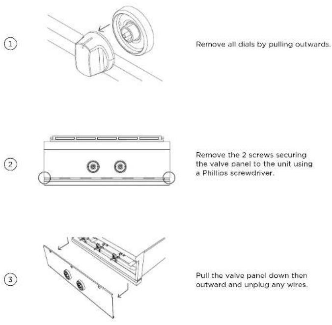
Removing the valve panel
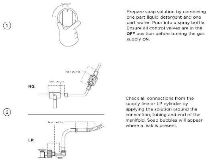
Testing for leaks
If a leak is present
Immediately turn the gas supply OFF and tighten any leaking connections. Turn gas ON, and recheck. If you cannot stop a gas leak turn the gas supply OFF and call your local gas utility or the dealer you purchased the appliance from. Only parts recommended by the manufacturer should be used on the side burner/griddle, substitution can void the warranty.
FLAMEHEIGHTADJUSTMENT
Flames should be blue and stable with no yellow tips, excessive noise or lifting (Note: LP units may have some yellow tipping). If any of these conditions exist, check the air shutter and burner ports are clear. If cleaning these does not improve performance, the air shutter can be adjusted.
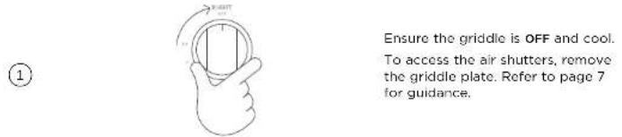
Ensure the griddle is OFF and cool. To access the air shutters, remove the griddle plate. Refer to page 7 for guidance.
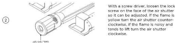
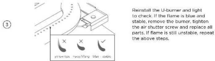
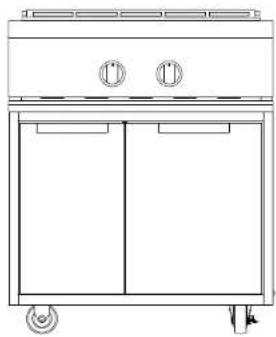
Designed with flexibility in mind, the 30" griddle can be either built-in or mounted on a freestanding cart. If the unit is to be placed onto a freestanding cart, an approved DCS cart is required and can be purchased separately from your local DCS dealer.
CAD1-30 freestanding cart part number: 71432
IMPORTANT!
- For further guidance, refer to the installation guide provided with your freestanding cart.
- Wear gloves when handling the cart, some edges may be sharp.
- Two or more people are required to move and assemble the cart.
- Push or pull the cart at the corners, do not move by the drawers or handles.
- To prevent tipping, do not push down on top of the drawers.
- For optimal use, this product should be located on a level surface with minimum flat area of 30 × 48'' (762 x 1219mm). Any bumps, cracks or protrusions should be less than 1/4'' .
- Do not overload the drawers. The maximum rating of each drawer is 35lbs.
Preparing the griddle
1
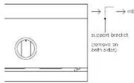
Remove the support brackets from the sides of the unit and replace with the supplied cart mount brackets.
2
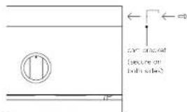
Secure cart mounting brackets using four of the supplied 10-24 x 1 / 2^ screws on each side.
(1)
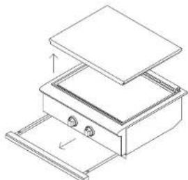
Remove the drip pan and any other removable components from the griddle.
②
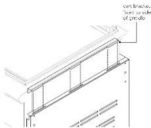
Place the griddle on the cart by locating the rear side tabs of the unit with the slots on the cart. Lower the griddle and locate the remaining tabs. The griddle should sit flush on the cart.
(3)
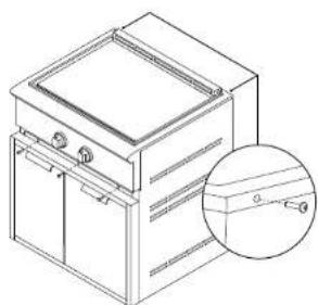
Secure the griddle to the cart with two Phillips-head screws at the rear and three at the front.
Replace any components removed in step 1 before referring to page 9 for gas connection advice.
INSTALLER CHECKLIST
Read all installation instructions in this manual to see if the unit has been correctly installed. Ensure that installation has been completed correctly before use.
Ensure that:
specified clearances are maintained to combustibles
proper enclosure ventilation has been verified
all internal packaging and any adhesive residue is removed
the burner is level and does not rock
□ dials turn freely, bezels centered
halolightingisfunctioningcorrectly
all warning labels removed and supplied to customer for future reference
flame has been adjusted
each burner lights satisfactorily - individually or with adjacent burner lit
the pressure regulator is connected and set for 4.0'' W.C.Natural,11.0"W.C.LP gas
the manual shut-off valve is installed and accessible
the unit has been tested and is free of leaks
the user is informed of gas supply shut-off valve location
Complete and keep for safe reference:
Model
Serial No.
Purchase Date
Purchaser
Dealer Address
Installer's Name
Installer's Signature
Installation Company
Installation Date
DCSAPPLIANCES.COM
Fisher & Paykel Appliances 2019. All rights reserved. The product specifications in this document apply to the specific products and models described at the date of issue. Under our policy of continuous product improvement, these specifications may change at any time. You should therefore check with your Dealer to ensure this booklet correctly describes the product currently available.
USCA
592068A 11.19

PLAQUE CHAUFFANTE
Modèle GDE1-30
GUIDE D'INSTALLATION
USCA
DANGER
SI VOUS DÉCELEZ UNE ODEUR DE GAZ
DIMENSIONS DU PRODUIT