MER30B12ASSC - Cooker MIDEA - Free user manual and instructions
Find the device manual for free MER30B12ASSC MIDEA in PDF.

User questions about MER30B12ASSC MIDEA
0 question about this device. Answer the ones you know or ask your own.
Ask a new question about this device
Download the instructions for your Cooker in PDF format for free! Find your manual MER30B12ASSC - MIDEA and take your electronic device back in hand. On this page are published all the documents necessary for the use of your device. MER30B12ASSC by MIDEA.
USER MANUAL MER30B12ASSC MIDEA
natural_image
Line drawing of a double oven with front panel and door (no text or symbols)ELECTRIC RANGE HOUSEHOLD
USER MANUAL
MER30B12AWWC
MER30B12ASSC
Warning notices: Before using this product, please read this manual carefully and keep it for future reference. The design and specifications are subject to change without prior notice for product improvement. Consult with your dealer or manufacturer for details.
The diagram above is just for reference. Please take the appearance of the actual product as the standard.
THANK YOU LETTER
Thank you for choosing Midea! Before using your new Midea product, please read this manual thoroughly to ensure that you know how to operate the features and functions that your new appliance offers in a safe way.
CONTENTS
THANK YOU LETTER EN-01
SAFETY INSTRUCTIONS EN-02
SPECIFICATION EN-10
PRODUCT OVERVIEW EN-11
PRODUCT INSTALLATION EN-13
OPERATION INSTRUCTIONS EN-30
CLEANING AND MAINTENANCE EN-45
TROUBLESHOOTING EN-49
TRADEMARKS, COPYRIGHTS AND LEGAL STATEMENT --- EN-54
DATA PROTECTION NOTICE EN-55
SAFETY DEFINITIONS
- Warnings and safety instructions in this manual do not cover all possible conditions and situations that may occur. It is your responsibility to use common sense, caution, and care when installing, maintaining, and operating your oven. Known hazards and their severity are identified in this manual with the following symbols:
- ⚠ WARNING
This symbol indicates the presence of a hazard which may result in death or serious injury if not avoided.
- ⚠️ CAUTION
This symbol indicates the presence of a hazard which may result in minor or moderate personal injury if not avoided.
- NOTICE
This symbol indicates the presence of a hazard which may result in minor property damage if not avoided.
- NOTE
This alerts the user to information that will help avoid confusion or common cooking mistakes and obtain the best possible user experience.
WARNING
Read all safety instructions before using this product. Failure to follow these instructions may result in fire, electrical shock, serious injury, or death. It is the owner's responsibility to ensure that anyone using the appliance knows how to operate it safely.
WARNING
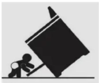
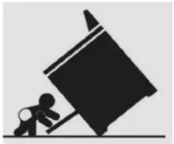
TIP OVER HAZARD
A child or adult can tip the range and be killed. Verify the anti-tip device has been properly installed and engaged per installation instructions. Ensure the anti-tip device is re-engaged when the range is moved. Do not operate the range without the anti-tip device in place and engaged. Failure to do so can result in death or serious burns to children or adults. Do not remove the leveling legs.
Doing so will prevent the range from being secured by the anti-tip device.
natural_image
Silhouette of a person pushing a large object on a horizontal surface (no text or symbols)Anti-Tip Bracket
text_image
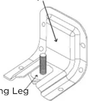
ing LegLeveling Leg
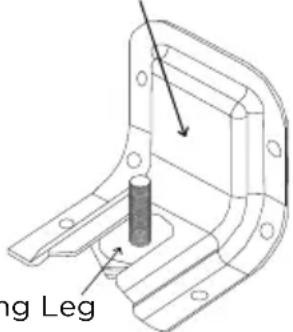
- To confirm the anti-tip bracket is properly installed, look underneath the range to confirm rear leveling leg is engaged in bracket. If visual inspection is not possible:
- Slide range forward
- Confirm anti-tip bracket is securely attached to floor or wall in correct position according to installation instructions.
- Fully slide the range back against the wall so that leveling leg engages with anti-tip bracket.
- If range is removed from service, secure door closed or remove door to minimize tip over risk. (See "Door" section under "Cleaning and Maintenance" in this manual for instructions on how to remove door.)
WARNING
INSTALLATION AND MAINTENANCE
- This appliance is intended for normal residential use. It is not approved for commercial use, outdoor installation, or any other application not specifically
allowed by this manual.
- Be sure your appliance is properly installed and grounded by a qualified service provider.
- DO NOT operate this appliance if it has been damaged or is not working properly. Contact a qualified service provider for repairs.
- DO NOT repair or replace any part of the appliance unless specifically recommended in the manual. All other servicing should be referred to a qualified service provider.
- This appliance requires connection to a 3-prong or 4-prong, 240VAC split phase, 60 Hz grounded electrical source. When installed, appliance must be electrically grounded in accordance with local codes or, in the absence of local codes, with the National Electrical Code, NFPA 70 or the Canadian Electric Code, CSA C21.1-02.
- DO NOT allow cooking grease or other flammable materials accumulate in or on the range. Grease in the oven or on the cooktop may ignite.
- Clean kitchen ventilating hoods frequently. Grease should not be allowed to accumulate on hood or filter.
- Clean cook-top with caution – To avoid steam burns, do not use wet sponge or cloth while cooking area is hot. Some cleaners can produce noxious fumes if applied to a hot surface.
- DO NOT use oven cleaners. No commercial oven cleaner or oven liner protective coating of any kind should be used with any part of this appliance.
- Do not clean door gasket – The door gasket is essential for a good seal. Care should be taken not to rub, damage, or move the gasket.
- Clean only parts and areas listed in the "Cleaning and Maintenance" section of this manual.
WARNING
GENERAL USAGE
- Do not store any flammable materials or temperature sensitive items inside oven, in storage drawer, or on top or near cooktop heating elements of the appliance.
- Never use your appliance for warming or heating the room.
- Children should not be left alone or unattended in the area where appliance is in use.
- Do not allow anyone to climb, stand, lean, sit, or hang on any part of an appliance, especially a door, drawer or operation panel.
- CAUTION - Do not store items of interest to children in cabinets above a range or on the backguard of a range - children climbing on the range to reach items could be seriously injured.
- Loose-fitting or hanging garments should never be worn while using the appliance.
- This appliance has not been evaluated for use with any 3rd party after-market systems. Do not attempt to use this appliance with a working or any other after-market device.
WARNING
CERAMIC GLASS COOKTOP
- The Hot Surface Indicator Light will glow if any surface cooking area is too hot to touch, even after the surface cooking area is turned off. Use caution as the cooktop surface may still be warm after the hot surface indicator light has shut off.
 | FIRE HAZARD |
| ·Never leave the range unattended·Turn off controls when not cooking·Failure to follow these instructions can result in death or fire·When range is in use, the entire cooktop may become hot! |
- The surface cooking area will glow red when an element is on. Some parts of the surface cooking area may not glow red when an element is on. This is normal operation. It will also randomly cycle off and back on again, even while on High, to keep the cooktop from extreme temperatures.
• To avoid damage to the cooktop, do not leave a hot lid on the cooktop. As the cooktop cools, air can become trapped between the lid and the cooktop, and the ceramic glass could break when the lid is removed.
- For foods containing sugar in any form, clean up all spills and soils as soon as possible. Allow the cooktop to cool down slightly. Then, while wearing oven mitts, remove the spills using a scraper while the surface is still warm. If sugary spills are allowed to cool down, they can adhere to the cooktop and can cause pitting and permanent marks.
- DO NOT USE WATER ON GREASE FIRES. Smother fire or flame with a close-fitting lid or metal tray. Never pick up a flaming pan. Dry chemical or foam-type extinguisher may be used if it is CLASS ABC or CLASS K and you already know how to use it.
- It is strongly recommended that a CLASS ABC or CLASS K fire extinguisher be kept near the range in an easily accessible location, and that household members are familiarized in advance with its operating instructions.
- Only certain types of glass, glass/ceramic, ceramic, earthenware, or other glazed utensils are suitable for range-top service without breaking due to the sudden change in temperature.
- To reduce the risk of burns, ignition of flammable materials, and spillage due to unintentional contact with the utensil, the handle of a utensil should be positioned so that it is turned inward, and does not extend over the front of the counter top or over adjacent cooktop heating elements.
- DO NOT TOUCH COOKTOP HEATING ELEMENTS OR AREAS NEAR ELEMENTS – Cooktop heating elements may be hot even though they are dark in color. Areas near cooktop heating elements may become hot enough to cause burns. During and after use, do not touch, or let clothing or other flammable materials contact cooktop heating elements or areas near elements until they have had sufficient time to cool. Among these areas are the cook-top and surfaces facing the cook-top.
- Use proper pan size. This appliance is equipped with cooktop heating elements of different size. Select utensils having flat bottoms large enough to cover the entire cooktop heating element heating element. The use of undersized utensils will expose a portion of the heating element to direct contact and may result in ignition of clothing. Proper relationship of utensil to burner will also improve efficiency.
- In the event that personal clothing or hair catches fire, drop and roll immediately to extinguish flames.
- Always turn hood ON when cooking at high heat or when flambéing food (i.e. Crepes Suzette, Cherries Jubilee, Peppercorn Beef Flambé).
- Hot oil is capable of causing severe burns. Never move cooking utensils containing hot grease. Wait until it has cooled before disposing of grease.
- Use high heat settings only when necessary. To avoid splattering, heat oil slowly on medium-low settings.
- In the event of house power failure, turn off any cooktop elements that were in use. This will prevent the cooktop from unexpectedly turning back on when power is restored.
WARNING
OVEN HAZARDS
- Never place anything (aluminum foil, spill mat, baking stone, cookware, etc.) on the bottom of the oven cavity. These items can trap heat or melt, resulting in damage to the appliance and risk of electric shock, smoke, or fire.
- Use care when opening the door. Let hot air or steam escape before removing or replacing food.
- Use only dry pot holders. Moist or damp pot holders on hot surfaces may result in burns from steam. Do not let pot holder touch hot grates or flames. Do not use a towel or other bulky cloth.
- Do not heat unopened food containers – Build-up of pressure may cause container to burst and result in injury.
- Do not obstruct oven vents.
- Always place oven racks in the desired location while oven is cool. If rack must be moved while oven is hot, do not let pot holder contact hot heating element in oven.
- DO NOT TOUCH OVEN HEATING ELEMENTS OR INTERIOR SURFACES OF OVEN - Heating elements
may be hot even though they are dark in color. Interior surfaces of an oven become hot enough to cause burns.
During and after use, do not touch, or let clothing or other flammable materials contact heating elements or interior surfaces of oven until they have had sufficient time to cool. Other surfaces of the appliance may become hot enough to cause burns – among these surfaces are oven vent openings and surfaces near these openings, oven doors, and windows of oven doors.
- Do not use a broiler pan without its insert. Do not cover the broiler insert with aluminum foil, as exposed fat and grease could ignite.
- If materials inside the oven should ignite, keep door closed and turn off power at the fuse or breaker box. Wait for the oven to cool before removing contents, cleaning the oven, and restoring power.
- Do not obstruct oven vents or any other slots or openings on the unit.
natural_image
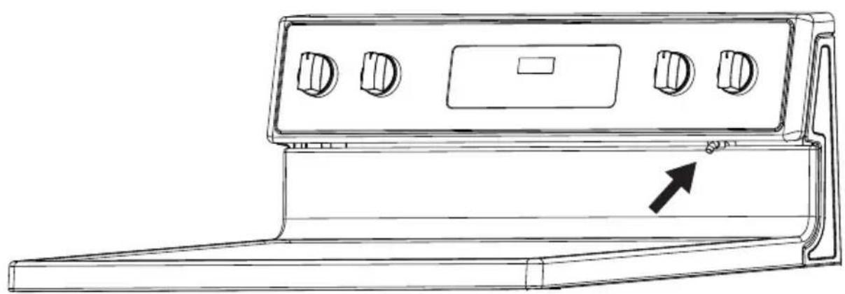
Line drawing of a door handle with control knobs and a directional arrow (no text or symbols)SPECIFICATION
MODEL MER30B12AWWC
/MER30B12ASSC
POWER SUPPLY
120/240V\~60Hz-9.65kW
120/208V\~60Hz-7.238kW
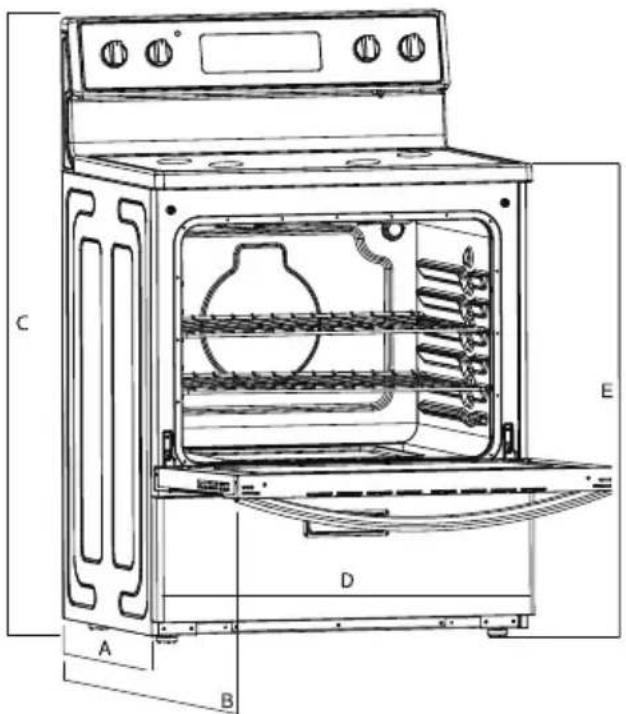
PRODUCT DIMENSIONS
A. 25.63" (65.1 cm) depth. Back of range to front of cooktop
B. 46.4" (117.9 cm) max. depth. Back of range to the top with the door opened
C. 46.38" (117.8 cm) overall height (max.) with leveling legs
D. 29.87"(75.9 cm) width
E. 35.9" (91.2 cm) cooktop height (max.) with leveling legs
text_image
Technical diagram of an oven with labeled components A, B, C, D, and E for identification.PRODUCT OVERVIEW
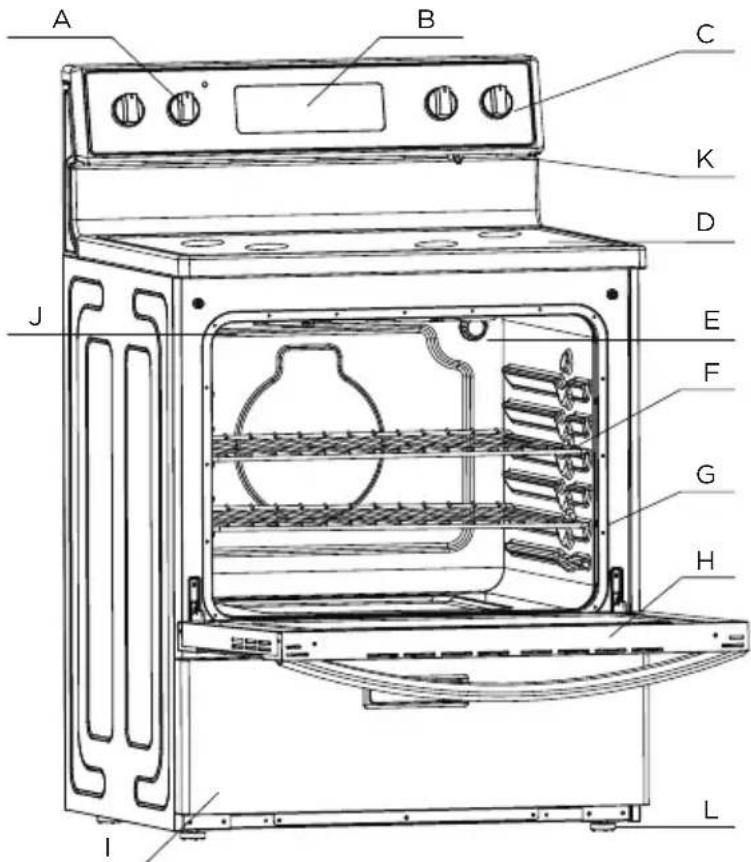
Range Parts Diagram
RANGE PARTS DIAGRAM:
A. Cooktop Knob
B. Control Panel
C. Cooktop Knob
D. Ceramic Glass Surface
E. Oven Light
F. Oven Racks
G. Gasket
H. Oven Door with Handle
I. Storage Drawer
J. Broiler
K. Oven Vent
L. Adjustable Feet x 4
text_image
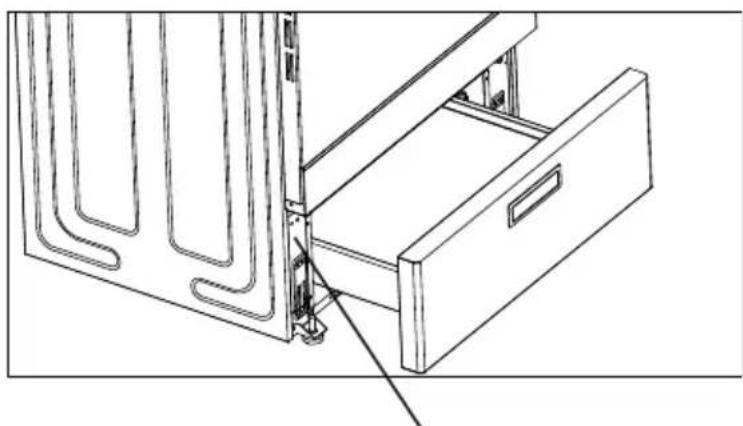
A B C K D J E F G H L IRating Plate Label Location:
- The rating plate label contains appliance certification, rating, and identification information. The model and serial number from the rating plate label is needed to register the product, order replacement parts, or when contacting customer service. The rating plate label is located in the left side of the front frame.
natural_image
Technical line drawing of a door drawer with internal structure and mounting bracket (no text or symbols)rating label position
 WARNING WARNING | CHOKING HAZARD |
| SMALL PARTS. NOT FOR CHILDREN UNDER 3 YEARS OLD. |
PRODUCT INSTALLATION
Safety Information
FOR YOUR SAFETY AND THE SAFETY OF OTHERS, PLEASE READ ALL SAFETY INSTRUCTIONS BEFORE INSTALLING THIS APPLIANCE.
There are important safety messages in this manual for this appliance. Failure to follow instructions may result in potential safety hazards to you or to the product, which may cause bodily injury. All saftey messages will explain what the potential hazards are, explain how to reduce the chance of injury, and state what can happen if the instructions are not followed.
MOBILE HOME INSTALLATION REQUIREMENT:
When this range is installed in a mobile home, it must be secured according to the instructions in this manual.
BEFORE STARTING INSTALLATION
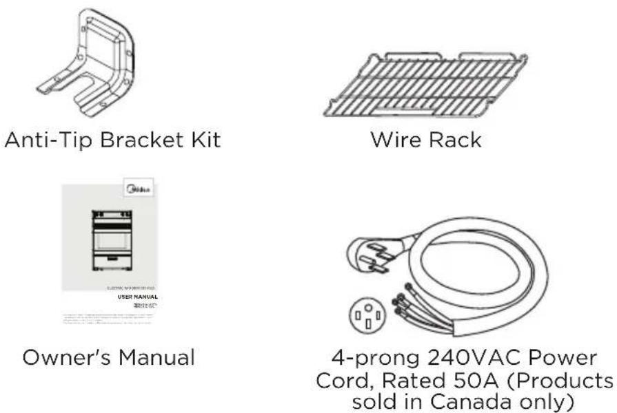
Parts Included with Product
Packed with the product are the following oven components and accessories. When product is first unpacked, verify that all these components are present. If anything is missing, check the packaging materials carefully for missing items. If items cannot be located, contact Midea customer service at 1-888-365-2230 or visit midea.com/ca/support for assistance.
Materials Needed:
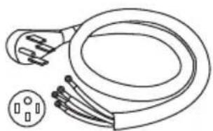
The utility connection and house structure at each home may be different, so the specific parts required for connection to the house are not included with the product. The parts identified below are or may be required to complete the installation. Always use new components - never use an old part for new range installation.
natural_image
Line drawing of a cord with two leads and a separate socket (no text or symbols)14-50P GETWIREDUSA FX359
(not applicable to products sold in Canada - these are provided with power cord)
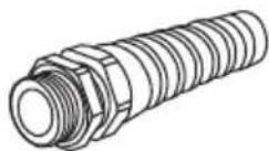
Strain Relief for Power Cord (supplied with cord kit)
natural_image
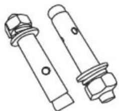
Technical line drawing of two bolted fasteners with hexagonal nuts (no text or symbols)5/16" OD Sleeve Anchor (with 1/4" bolt) - 2 pcs (for concrete floors only)
Tools Needed:
To complete the installation, have the following tools readily available:
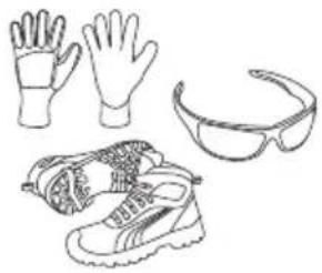
natural_image
Line drawings of various outdoor gear and footwear items including gloves, shoes, and goggles (no text or symbols)Cut Resistant Gloves, Safety Glasses or Goggles, and Steel-Toed Shoes (for your safety and protection)
natural_image
Two hand-drawn sketch of folded paper sheets (no text or symbols)Drop Cloth or Cardboard (optional - to protect floor)
Tape Measure (to confirm installation space)
Phillips Screwdriver (to access serviceable covers)
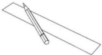
Nut Driver Pencil and Ruler (for electrical connections) (for anti-tip bracket installation)
natural_image
Simple line drawing of a pencil resting on a rectangular sheet (no text or symbols)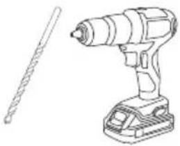
natural_image
Line drawing of a drill press and a cylindrical tool (no text or symbols)Drill and 1/8" Drill Bit (for anti-tip bracket installation)
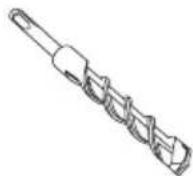
Masonry Drill Bit (for anti-tip bracket installation - concrete floors only)
natural_image
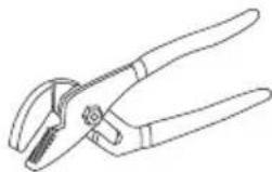
Line drawing of a pair of pliers (no text or symbols)Adjustable Groove -Joint or Gooseneck Pliers (for leveling product)
Level (for leveling product)
Remove Old Appliance

WARNING
FIRE, EXPLOSION HAZARD
- Installation and service must be performed by a qualified installer or service agency.

CAUTION
LACERATION, FOREIGN OBJECT, CRUSH HAZARD
- When installing, moving, or servicing any appliance, wear proper protective equipment, including cut resistant gloves, steel-toed shoes, and safety glasses.
If the new range is replacing an existing installation, first remove the old appliance.
Directions:
- Shut off the electrical supply to the range at the breaker box or fuse box. Leave it off until the installation has been completed.
- Move appliance to access the electrical connections.
- Disconnect electrical connections and move appliance out of and away from installation space.
Electrical Supply Requirements

WARNING
ELECTRICAL SHOCK HAZARD
- Installation must be electrically grounded in accordance with local codes or, in the absence of local codes, with the National Electrical Code, NFPA 70 or the Canadian Electric Code, CSA C22.1-02.
Clearances and Dimensions:

IMPORTANT
TO PREVENT DAMAGE TO CABINETS
- This range has been designed to comply with the maximum allowable wood cabinet temperature of 194 °F (90 °C). Make sure the wall coverings, countertops, cabinets, and any other materials in contact with the range are rated for a minimum of 194 °F (90 °C). If not, discoloration, delamination, or melting may occur.
Before starting the installation process, confirm the installation space meets the following dimensions and clearances. Do not locate the range where it may be subject to strong drafts - seal any openings in the wall, floor, or cabinets in the installation space. Provide adequate clearances between the range and adjacent combustible surfaces. These dimensions must be met for safe use of the range. The given dimensions provide minimum clearance. Contact surface must be solid and level.
The minimum clearance is 0" for the rear of the range. Follow all dimension requirements to prevent property damage, potential fire hazard, and incorrect countertop and cabinet cuts.
Countertop surfaces immediately around installation space must be flat and level for proper installation.
This appliance must not be installed with a ventilation system that blows air downward toward the range. This type of ventilation system may cause ignition and combustion problems with the gas cooking appliance resulting in personal injury or unintended operation.
When the floor covering (hardwood flooring, tile, carpet, etc.) ends at the front of the range, the area that the range will be installed on must be built up with plywood to the same level or higher than the floor covering. This will allow the range to be moved for cleaning and servicing, as well as provide proper air flow to the range.
Ensure floor covering material can resist temperatures of at least 167 °F (75 °C). Ensure the wall coverings, countertops, cabinets, and any other materials in contact with the range can resist the heat generated up to 194 °F (90 °C) by the range.
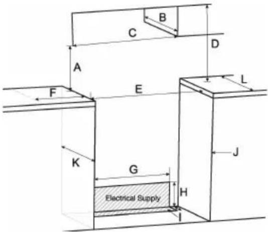
CABINET DIMENSIONS
Cabinet opening dimensions shown are for 26" (66.0 cm) countertop depth, 24" (61.0 cm) base cabinet depth and 36" (91.4 cm) countertop height.
A. 18" (45.7 cm) upper side cabinet to countertop
B. 13" (33 cm) maximum upper cabinet depth
C. 30-1/8"(76.5 cm) minimum opening width
D. For minimum clearance to top of cooktop, see “*WARNING” below.
E. 30-1/8"(76.5 cm) minimum opening width
F. 3" (7.6 cm) minimum clearance from both sides of range to side wall or other combustible material.
G. 27"(68.7 cm)
H. 7-4/5" (19.8 cm)
- 3-1/5"(8 cm)
J. Cabinet door or hinges should not extend into the cutout.
K. 24" (61.0 cm) base cabinet depth
L. 26" (66.0 cm) tabletop width of base cabinet

WARNING
Allow 30" minimum clearance between surface units and bottom of unprotected wood or metal cabinet, or allow a 24" (61.0 cm) minimum when bottom of wood or metal cabinet is protected by no less than 1/4" (0.64 cm) thick flame retardant millboard covered with not less than No 28 MSG sheet metal [0.015" (0.4mm)], 0.015" (0.4 mm) thick stainless steel, 0.024" (0.6 mm) aluminum or 0.020" (0.5 mm) copper.
text_image
C B D A F E L K G H J Electrical Supply IPackaging Removal:

IMPORTANT
TO PREVENT DAMAGE TO APPLIANCE
- Failure to remove packaging materials could result in damage to the appliance.
Remove all tape and packaging materials. Check for film on stainless steel parts, padding/spacers on and around door and face of oven, cardboard and plastic on and around racks, inside storage drawer, etc. Do not use sharp instruments, rubbing alcohol, flammable fluids, or abrasive cleaners to remove tape or glue.
These products can damage the surface of your range.
Inventory all loose parts against the "Parts Supplied" list.
Check for shipping damage and/or missing parts. Any damage and/or missing parts should be reported to your local retailer.
To reduce the weight of the range while being moved, adjusted, and installed, leave the oven racks, and any other accessories to the side until they are ready to be installed later in these instructions.
Electrical Connection
For power requirements, refer to the following table.
ELECTRICAL SUPPLY CONNECTION:

WARNING
ELECTRICAL SHOCK HAZARD
- Installation must be electrically grounded in accordance with local codes or, in the absence of local codes, with the National Electrical Code, NFPA 70 or the Canadian Electric Code, CSA C22.1-02.
- Do not use an extension cord with this product.
- The power supply cord and plug should not be modified. If it will not fit the outlet, have a proper outlet Installed by a qualified electrician.
- Remove the house fuse or open the circuit breaker before beginning installation.
- Effective January 1, 1996, the National Electrical Code requires that new construction (not existing) utilize a 4-conductor connection to an electric range.
- Be sure your appliance is properly installed and grounded by a qualified service provider.
This appliance must be supplied with the proper voltage and frequency, and be connected to an individual, properly grounded branch circuit, protected by a circuit breaker or fuse having amperage as specified on the rating plate. The rating plate label is located in the left side of the front frame. After installation, instruct the resident/owner where the main range electrical disconnect is located and how to operate it.
A 3-wire or 4-wire, split-phase AC 208Y/120 Volt or 240/120 Volt, 60 hertz electrical system must be used.
If the electrical service provided does not meet the above specifications, have a licensed electrician install an approved outlet.
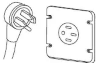
Use only a 3-conductor or a 4-conductor UL-listed range cord rated 40A or 50A. These cords may be provided with crimped ring or fork terminals on the wire. A strain relief device must be used when attaching the cord to the range. Because range terminals are not accessible after the range is in position, a flexible service conduit or cord must be used. Allow 2-3 ft of slack in the line so that the range can be moved if servicing is ever necessary.
For Canadian installations, simply plug the attached power cord to the residential outlet. Outlet must be properly grounded and in accordance with the Canadian Electrical Code (CSA Standard C22.1 Part 1) and any local electrical code requirements.
natural_image
Technical line drawing of a plug and its corresponding socket (no text or symbols)This oven is manufactured with a neutral (white) power supply wire and a cabinet-connected green (or bare) ground wire twisted together.
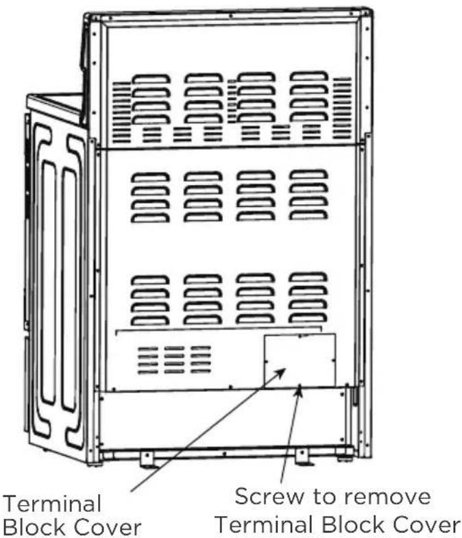
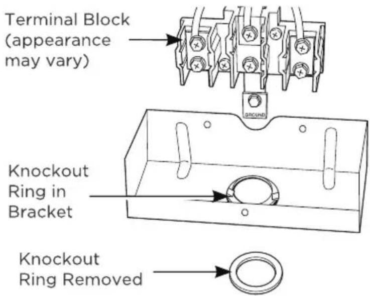
A. To access the terminal block, remove the terminal block cover by removing screws using a phillips screwdriver. Do not discard these screws.
B. For power cord and 1" conduit only, remove the knockout ring [1-3/8" (3.5 cm)] located on bracket directly below the terminal block. To remove the knockout, use a pair of pliers to bend the knockout ring away from the bracket and twist until the ring is removed.
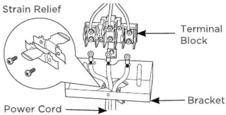
C. For power cord installations only (see the next step if using conduit), assemble the strain relief in the hole. Insert the power cord through the strain relief and tighten. Allow enough slack to easily attach the cord terminals to the terminal block. If tabs are present at the end of the winged strain relief, they can be removed for better fit.
text_image
Terminal Block Cover Screw to remove Terminal Block Cover
NOTICE
Do not install the power cord without a strain relief. The strain relief bracket MUST be installed before reinstalling the terminal block cover. You must purchase a cord at the desired length that matches the receptacle configuration correctly.

NOTICE
Next to this knockout ring [1-3/8" (3.5 cm)], a knockout ring [1-1/8" (2.9 cm)] is reserved for installation to match some models of power cord and conduit.
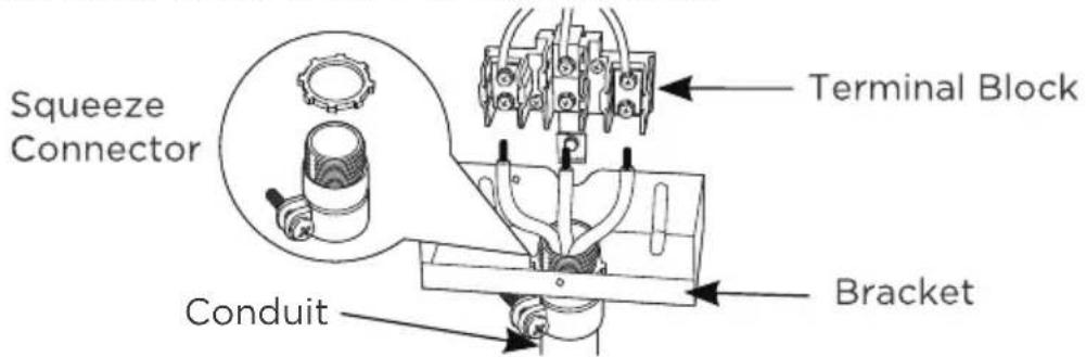
D. For 3/4" conduit installations only, pur chase a squeeze connector matching the diameter of your conduit and as semble it in the hole. Insert the conduit through the squeeze connector and tighten. Allow enough slack to easily attach the wires to the terminal block.

NOTICE
Do not install the conduit without a Squeeze connector.
text_image
Terminal Block (appearance may vary) Knockout Ring in Bracket Knockout Ring RemovedThe Strain relief MUST be installed before reinstalling the terminal block cover.
text_image
Strain Relief Terminal Block Power Cord BracketE. Replace wire cover on range back and replace the screws removed earlier. Make sure that no wires are pinched between cover and range back. Replace the terminal block cover if it was removed.
text_image
Squeeze Connector Terminal Block Conduit BracketBEFORE: POWER CORD AND CONDUIT
text_image
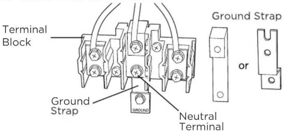
Terminal Block Ground Strap Neutral Terminal Ground Strap orEN-21
4-Prong Power Cord Directions
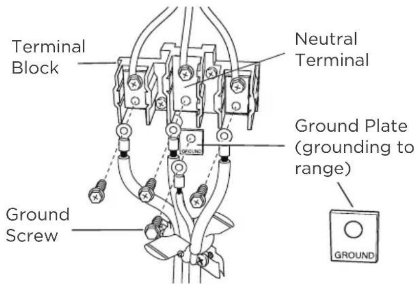
IMPORTANT: The neutral wire of the supply circuit must be connected to the neutral terminal located in the lower center of the terminal block. The power leads must be connected to the lower left and the lower right terminals of the terminal block. The grounding lead must be connected to the frame of the range with the ground plate and the green ground screw.
FOR POWER CORD INSTALLATION
A. Remove the 3 lower terminal screws from the terminal block. Remove the ground screw and ground strap and retain them. Discard the ground strap. DO NOT DISCARD ANY SCREWS.
B. Insert the one ground screw into the power cord ground wire terminal ring, through the ground plate and into the frame of the range.
C. Insert the 3 terminal screws (removed earlier) through each power cord terminal ring and into the lower tenninals of the terminal block. Be certain that the center wire (white/neutral) is connected to the center lower position of the terminal block. Tighten screws securely into the terminal block. Do not overtighten the screws.
After: Power Cord
text_image
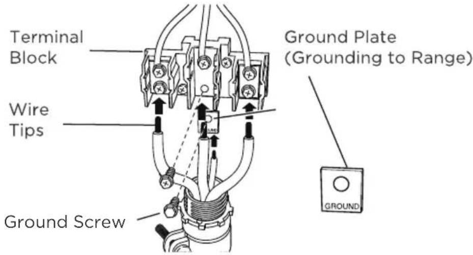
Terminal Block Neutral Terminal Ground Plate (grounding to range) Ground Screw GROUNDFOR CONDUIT INSTALLATION
A. Loosen the 3 lower terminal screws on the terminal block. Strip wire to exposed tip about 5/8" long.
B. Insert the center (white/neutral) wire tip through the bottom center terminal block opening. On certain models, the wire will need to be inserted through the ground strap opening and then into the bottom center block opening. Insert the two side bare wire tips into the lower left and the lower right terminal block openings.
C. Tighten the screws until the wire is firmly secured (35 to 50 inch-lbs.). Do not overtighten the screws.
After: Conduit
text_image
Terminal Block Wire Tips Ground Screw Ground Plate (Grounding to Range) GROUND
CAUTION
ALUMINUM WIRING: Aluminum building wire may be used but it must be rated for the correct amperage and voltage.
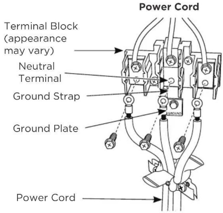
3-PRONG POWER CORD DIRECTIONS
IMPORTANT: The neutral or ground wire of the power cord must be connected to the neutral terminal located in the lower center of the terminal block and the ground strap must connect the neutral terminal to the ground plate. The power leads must be connected to the lower left and the lower right terminals of the terminal block.
DO NOT remove the ground strap connection.
FOR POWER CORD INSTALLATION
A. Remove the 3 lower terminal screws from the terminal block.
B. Insert the 3 terminal screws through each power cord terminal ring and into the lower terminals of the terminal block. Be certain that the center wire (white/neutral) is connected to the center lower position of the terminal block.
C. Tighten screws securely into the terminal block. DO not overtighten the screws.
FOR CONDUIT INSTALLATION
A. Loosen the 3 lower terminal screws on the terminal block. Strip wire to expose tip about 5/8" long.
B. Insert the center (white/neutral) wire tip through the bottom center terminal block opening. On certain models, the wire will need to be inserted through the ground strap opening and then into the bottom center block opening. Insert the two side bare wire tips into the lower left and the lower right terminal block openings.
C. Tighten the screws until the wire is firmly secured (35 to 50 inch-lbs.). Do not overtighten the screws.

CAUTION
Aluminum Wiring: Aluminum building wire may be used but it must be rated for the correct amperage and voltage.
text_image
Power Cord Terminal Block (appearance may vary) Neutral Terminal Ground Strap Ground Plate Power Cord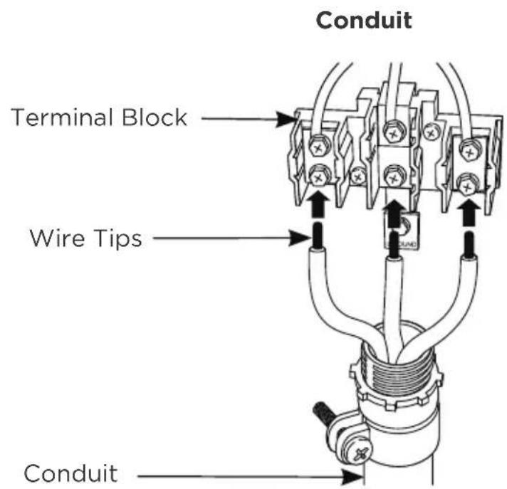
text_image
Conduit Terminal Block Wire Tips ConduitANTI-TIP BRACKET INSTALLATION
| WARNING | TIP OVER HAZARD |
 | A child or adult can tip the range and be killed.Verify the anti-tip device has been properly installed and engaged per installation instructions.Ensure the anti-tip device is re-engaged when the range is moved. |
| Anti-Tip Bracket | Do not operate the range without the anti-tip device in place and engaged. Failure to do so can result in death or serious burns to children or adults. Do not remove the leveling legs.Doing so will prevent the range from being secured by the anti-tip device. |
 Levelir Levelir |
To reduce the risk of tipping of the range, the range must be secured to the floor by the properly installed anti-tip bracket and screws packed with the range. Failure to install the anti-tip bracket will allow the range to tip over if excessive weight is placed on an open door or if child climbs upon it. Serious injury might result from spilled hot liquids or from the range itself.
The anti-tip kit is provided with the range. If the anti-tip bracket is missing, damaged, or needs replaced, a replacement kit will be provided free-of-charge by contacting Midea customer service at 1-888-365-2230 or by visiting midea.com/ca/support.
If range is ever moved to a different location, the anti-tip brackets must also be moved and installed with the range. If range is removed from service, secure door closed or remove door to minimize tip over risk.
(See "Door Removal and Reinstallation" section in this manual or under "Cleaning and Maintenance" in the User's Manual for instructions on how to remove door.)
HOW TO INSTALL ANTI-TIP BRACKET
- Remove the anti-tip bracket from where it is taped on Oven Rack inside the Oven.
- Determine which mounting method to use: floor or wall. If you have a stone or masonry floor, you can use the wall mounting method. If you are installing the range in a mobile home, you must secure the range to the floor.
-
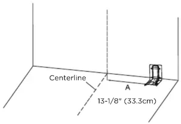
Determine and mark centerline of the cutout space. The mounting can be installed on either the left side or right side of the cutout. Position mounting bracket against the wall in the cutout so that the V-notch of the bracket is 13-1/8" (33.3 cm) from centerline as shown.
-
Attach anti-tip bracket to floor or wall.
-
Wood Construction Installation: Drill a 1/8" pilot hole where screws are to be located. If bracket is to be mounted to the wall, drill pilot hole at an approximate 20° downward angle. Screw must enter wood.
- Masonry Construction Installation: Due to the variety of masonry materials that may be present at installation site, hardware is not provided for attaching the anti-tip bracket to masonry. If bracket is to be mounted to masonry or ceramic floors, attach anti-tip bracket using two 5/16" OD sleeve anchors (with 1/4" bolt - either hex bolt head or hex nut head) rated for minimum 300lb tension for the masonry material present at installation site.
text_image
Centerline 13-1/8" (33.3cm) AANTI-TIP BRACKET
(FLOOR MOUNTING ONLY)
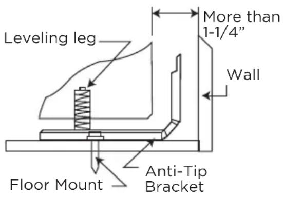
text_image
Leveling leg More than 1-1/4" Wall Floor Mount Anti-Tip Bracket- Check to make sure the back leg of the range has engaged properly into the anti-tip bracket.
If visual inspection is not possible:
- Slide range forward
- Confirm anti-tip bracket is securely attached to floor or wall in correct position according to installation instructions.
- Fully slide the range back against the wall so that leveling leg engages with anti-tip bracket.
natural_image
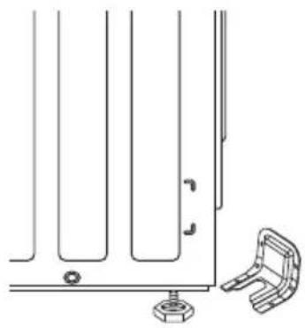
Technical line drawing of a mechanical bracket assembly with mounting holes and a separate clamping bracket (no text or symbols)DOOR REMOVAL AND REINSTALLATION:
WARNING FIRE HAZARD
- If door is removed, confirm that door operates correctly and seals properly when reinstalled. If door gasket does not seal completely, heat escaping from around doors could ignite cabinetry.
During installation, service, gas conversion, and leveling, it may be easier to perform the necessary work if the oven door is removed. This makes the appliance lighter and access to the oven cavity easier. Follow these instructions below to remove and reinstall the door.
Door can be removed for easier cleaning, servicing, or installation:
- Open door full
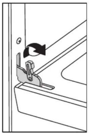
- On each door hinge, flip down the lock mechanism so that it engages with the door when the door is rotated towards being closed.
- Once both lock mechanisms are engaged, continue to rotate do until \~2-3 inches from being fully closed.
- Grasp door firmly from the sides and lift door up and out from oven face. Do not lift door by door handle to reduce risk of broken door glass.
natural_image
Diagram of a mechanical clamp or bracket assembly with rotation arrow (no text or symbols)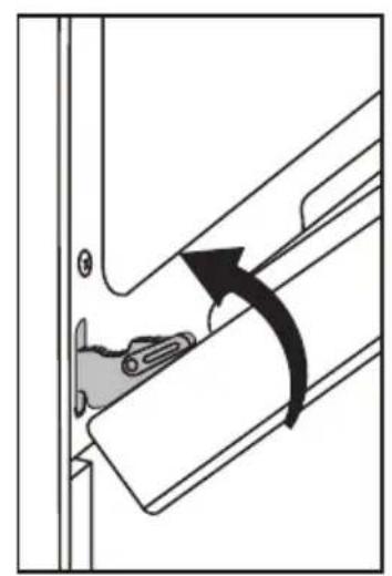
natural_image
Diagram showing a mechanical component with an arrow indicating rotational motion (no text or symbols present)
natural_image
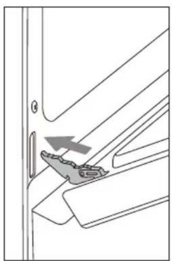
Diagram of a door handle with a bracket and directional arrow (no text or symbols)REINSTALLING DOOR:
- Holding door from the sides, align door so that hinges slip back into openings.
- Rotate door until \~2-3 inches from being fully closed, allow door to drop into notches on hinges.
- Rotate door out until fully open.
- Flip the hinge locking mechanism back up and away from the door.
- Check that door opens and closes correctly.
- If door does not operate correctly, re-engage locking mechanisms, remove door, and reattempt installation.
natural_image
Technical line drawing of a mechanical bracket with an arrow indicating a specific part (no text or symbols present)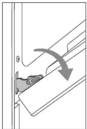
natural_image
Diagram showing a mechanical component with an arrow indicating direction, no text or symbols present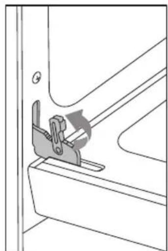
natural_image
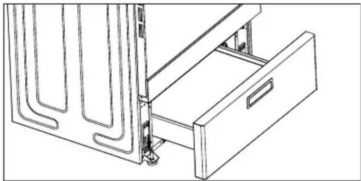
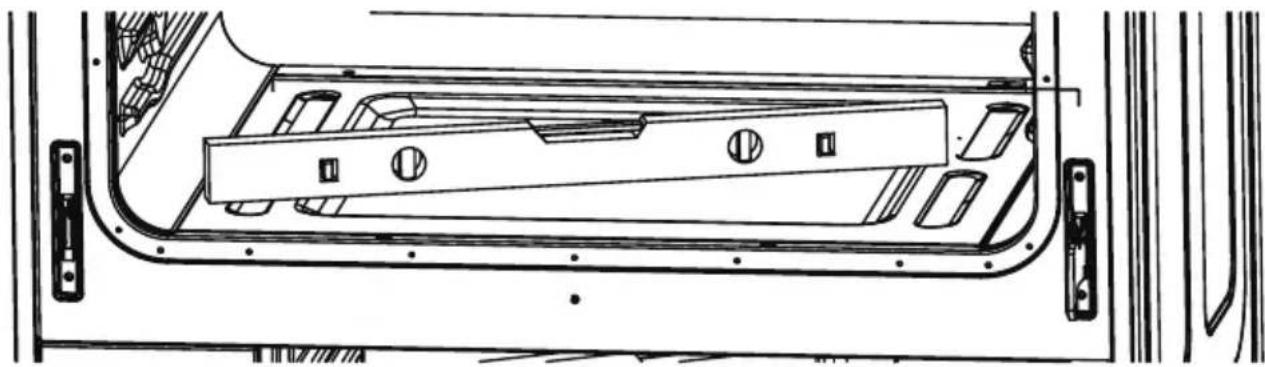
Technical line drawing of a mechanical clamp or bracket assembly (no text or symbols)Drawer Removal and Reinstallation:
During installation, service, and leveling, it may be easier to perform the necessary work if the drawer is removed. This makes the appliance lighter and visibility of anti-tip bracket is improved.
Follow these instructions below to remove and reinstall the drawer.
To remove drawer, fully extend drawer and pull up, then pull out the drawer.
To reinstall the drawer, align the rails on the drawer with the slides on the range and push drawer in until fully closed. Open and close drawer to ensure slide rails are operating properly.
natural_image
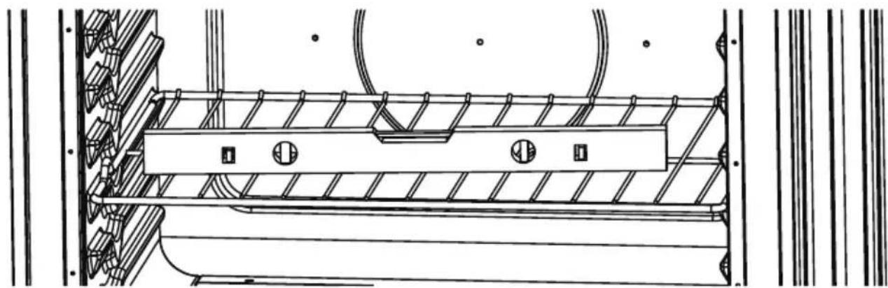
Technical line drawing of a mechanical device with a drawer and metal frame (no text or symbols)LEVEL RANGE
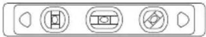
HOW TO LEVEL THE RANGE:
- To level your range, place a level straight across (left to right), on one of the racks inside your oven. If the range is uneven, adjust the leveling legs until the level is balanced. (Leveling legs are on the bottom of the range and can be adjusted by turning the feet clockwise or counter clockwise.
natural_image
Technical line drawing of a mechanical assembly with ribbed and mounting components (no text or symbols)- Once you have checked the leveling from left to right, take another reading by moving the level and placing it diagonally across the bottom of the oven. If the range is still uneven, adjust the leveling legs again until all angles on the level are balanced.
natural_image
Technical line drawing of a vehicle door frame with internal compartments and mounting brackets (no text or symbols)OPERATION INSTRUCTIONS
Review Of Controls:
CONTROL PANEL DIAGRAM
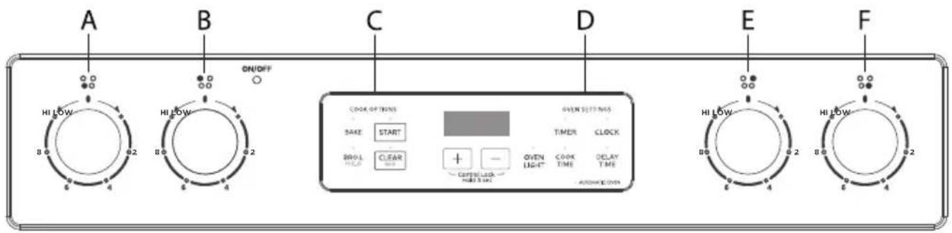
text_image
A HI LOW 8.0 6.2 B HI LOW 8.0 6.2 ON/OFF C COOK OPTIONS SAKE START BOWL CLEAR + - OXYL LIGHT OXYL TIME OXYL TIME OXYL TIME OXYL TIME D OXYL TIME E HI LOW 8.0 6.2 B HI LOW 8.0 6.2 F| A | FRONT LEFT BURNER | C | OVEN COOKING OPTIONS | E | REAR RIGHT BURNER |
| B | REAR LEFT BURNER | D | OVEN SETTINGS F | FRONT | RIGHT BURNER |
CONTROL KNOB
- The control knobs can be set to anywhere between "HI" to "LOW".
- Push in and turn to activate.
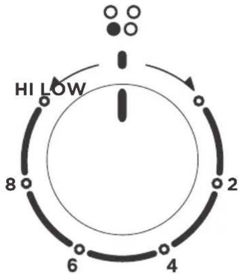
text_image
HI LOW 8 2 6 4When the unit is powered for the first time or in case of a power outage, the control will display "12:00" and will be flashing until the time is set.
When the oven is OFF, the control will display the daytime.
BEFORE USING YOUR NEW RANGE FOR THE FIRST TIME:
- Ensure all packaging, literature, removable labels, and protective plastic film are removed. Check inside oven, inside drawer, and around door and trim edges carefully.
- While cool, wipe down all surfaces, including inside oven and drawer, with a damp cloth to remove dust that may have settled during shipping and storage.
- Familiarize yourself with the controls and features described in this manual.
- Confirm that surface elements and oven operate as intended. Contact Midea customer service at 1-888-365-2230 or by visiting midea.com/ca/support immediately if appliance is not working as expected.
- Start the oven in BAKE mode at the highest available temperature setting. Allow oven to run for 1 hour to remove any dust or impurities. There will be a distinctive odor - this is normal. Ensure your kitchen is well ventilated during this conditioning period.

NOTE
- The clock function on this range has two available time settings. 12-hour or 24-hour time.
- The range is programmed with the 12-hour time mode set as the default setting.
- Before setting the clock, make sure the oven and timer are off.
- If you would like to change the time mode from the default setting, you must change it before setting the clock.
HOW TO SELECT THE 12-HOUR OR 24-HOUR TIME SETTING:
- To switch the clock mode from 12-hour or 24-hour time, press the "CLOCK" pad, and hold for 3 seconds.
- After 3 seconds, 12 or 24 will appear on the display.
- If the display shows "12" you are switching the time mode to 12-hour time.
- If the display shows “24” you are switching the time mode to 24-hour time.
- Once your desired time mode appears, the display will automatically switch back to the clock display indicating that your time mode has been updated.
HOW TO SET THE CLOCK
After the desired time setting mode has been selected you can now set the clock time on the range.
- To set the clock, press the "CLOCK" pad, and the hours will begin to flash, press the "+ or -" pad to adjust the hour. To lock in the hour, press the "CLOCK" pad.
- Once the hour is locked in, the minutes will begin to flash on the display, next press the “+ or -” pad to adjust the minutes. To lock in the minutes, press the “CLOCK” pad.
- The clock time on your range is now set.
CLEAR/OFF
The CLEAR/OFF pad stops any function except the Control Lock.
OVEN LIGHT
Press the “OVEN LIGHT” pad to turn the lights on or off. When the “Bake” or “Broil” start, the Oven Light will light up automatically.
START
The “START” Pad begins the oven function. If the “START” pad is not pressed within 30 seconds after pressing a function pad, the display will begin to flash for 30 seconds, then 5 reminder tones will sound, and “PUSH” icon and “On” icon will begin to flash alternately on the display for 30 seconds. If the “START” pad is not pressed the oven function will be canceled and the display will return to showing the clock time.
TIMER
The timer can be set in hours or minutes up to 11 hours and 59 minutes (in the 12-hour time mode; 23-hours and 59 minutes in the 24-hour time mode), and counts down the set time programmed into the system. The timer does not start or stop the oven.
HOW TO SET THE TIMER
- To set the Timer, press the "TIMER" pad. The Timer indicator light will light up.
- Next, the display will begin to flash, to set the desired hour or minutes, press the “+ or -” pad.
- Then press the "TIMER" pad to begin the Timer.
- When the set time ends, the end-of-cycle tones will sound.
- Press the "TIMER" pad to stop the timer and the reminder tones.

NOTES
If you would like to stop the Timer at any time, press the "TIMER" pad twice.
OVEN TEMPERATURE FORMAT
- The default temperature scale setting for the oven is set to Fahrenheit.
- When using the oven, the oven temperature on the display will appear in Fahrenheit (F).
- However, if you would like to change the temperature scale to Celsius (C), please see directions below.
HOW TO CHANGE THE OVEN TEMPERATURE SCALE TO CELSIUS:
- To change the oven temperature scale to Celsius (C), press the "BAKE" pad and hold for 3 seconds.
- Next, the letter "C" will appear on the display for a few seconds.
- The “C” will disappear from the display, and the clock time will reappear on the display indicating the oven temperature scale has been switched.
- When using the Bake function, the oven temperature will now display the letter "C" next to the temperature.
HOW TO CHANGE THE OVEN TEMPERATURE SCALE BACK TO FAHRENHEIT:
- To change the oven temperature scale back to Fahrenheit (F), repeat above steps 1-3. However, during the adjustment the letter “F” will appear on the display instead of a “C”.
LOCK CONTROLS
The Lock Controls function locks the control panel pads from being used to avoid any unintended use of the cook functions. When the control panel is locked, only the Oven Light will function.
To Lock/Unlock Control Panel:
- To lock the control panel, press both the “+ and -” pads at the same time and hold for three seconds, then “LOC” icon will appear on the display and begin to flash. Once “LOC” stops flashing, your control panel is now locked.
- To unlock the control panel, press both the “+ and -” pads at the same time and hold for three seconds, then “OPN” icon will appear on the display and begin to flash. Once “OPN” icon stops flashing, your control panel is now unlocked.
| WARNING | LOCK CONTROLS |
| LOCK CONTROLS FUNCTION DOES NOT LOCK THE OVEN DOOR. | |
REMOVING/INSERTING RACKS:

CAUTION
BURN HAZARD
- Always place oven racks in the desired location while oven is cool. If rack must be moved while oven is hot, do not let pot holder contact hot oven surfaces.
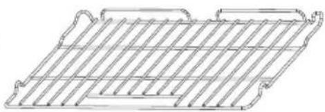
Oven Racks:
Flat Rack: Versatile and low profile, each range is supplied with one or more flat oven racks. Flat racks slide in and out of oven on rack guides formed into side of oven wall. Multiple racks can be used simultaneously, if desired. If racks do not move smoothly, use the corner of a paper towel to apply a thin layer of vegetable oil to reduce friction. Wipe off any excess before use.
natural_image
Line drawing of a grid-like structure with no text or symbolsRemoving Rack: Racks are designed to stop before coming completely out of the oven to reduce the risk of dropped or spilled foods. To remove the rack:
- Remove all food and utensils from rack.
- Grasp firmly from both sides.
- Pull rack out until it contacts the stop position.
- Lift up on the front of the rack and continue pulling outward.
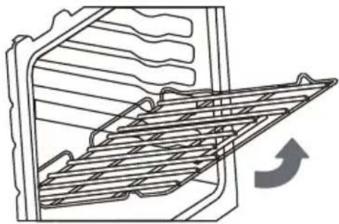
natural_image
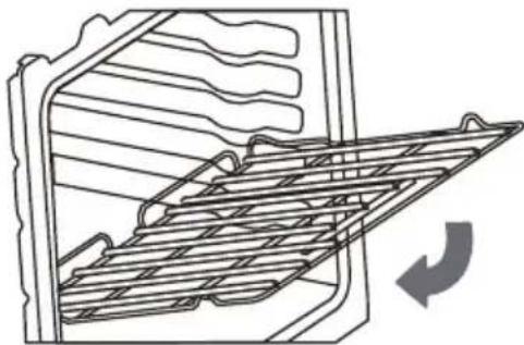
Line drawing of a refrigerator interior with a rack-mounted ventilation grille and a curved arrow indicating airflow (no text or symbols)Inserting Rack: The rack can be installed in only one direction.
To insert the rack:
- Orient the rack so that the handle is towards the front and the interlock features are on the top side.
- Tip rack so that the front is several inches higher than the back.
- Slip the interlock features under the stop position on the rack guides formed in the oven walls.
- Rotate rack down while pushing back to complete the insertion process.
natural_image
Line drawing of a refrigerator interior with a grater rack and ventilation slots (no text or symbols)Rack Positions:
For best performance, adjust rack so food is placed at the center of the oven. For most foods this will be rack position #3
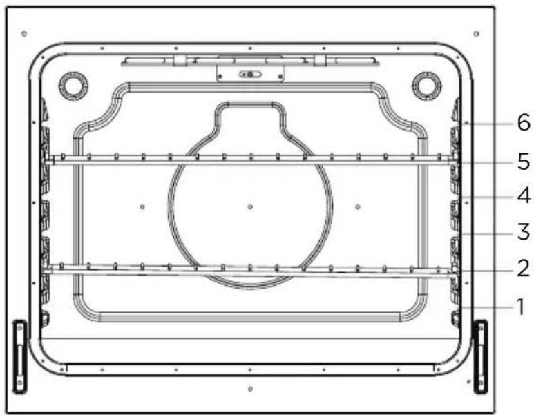
text_image
1 2 3 4 5 6OVEN FUNCTION RACK POSITION
| BAKING | |
| Large Roast/Turkey Use Rack 1 | |
| Meat/Poultry Use Rack 2 | |
| Cake/Cookies Use Rack 3 | |
| Batch Baking Use Rack 2 and 5 | |
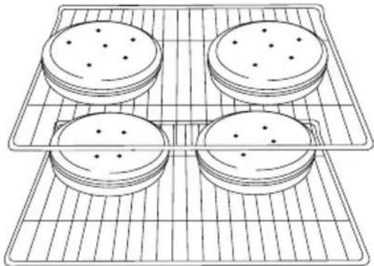
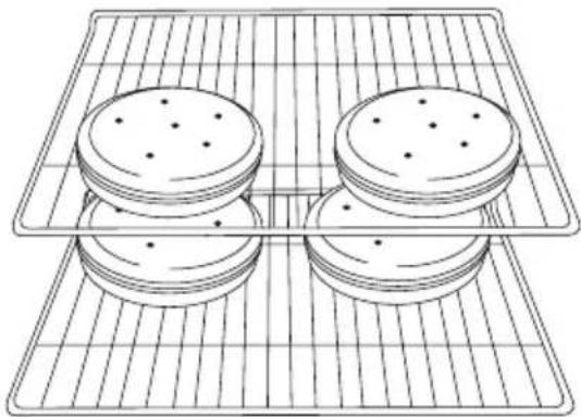
For best results when baking layer cakes on 2 racks, use racks 2 and 5 in the lower and upper section of the oven. For an even bake, stagger the cake pans on the bottom rack so that it is not positioned directly below the pans on the top rack. Place the cake pans on the racks as shown in the illustration below. (Diagram A)
natural_image
Line drawing of four rectangular crackers arranged on a grid-lined baking tray (no text or symbols)For best results when baking layer cakes on 2 racks in the middle section of the oven, use racks 3 and 5. For an even bake, stagger the cake pans on the bottom rack so that it is not positioned directly below the cake pans on the top rack. Place the cake pans on the racks as shown in the illustration below. (Diagram B)
natural_image
Line drawing of four rectangular crackers arranged on a grid-lined rack (no text or symbols)
NOTES
- Please wear an oven mitt when touching the oven racks or placing food in/ removing food from the oven!
- During cooking, if you want to change the temperature, you must first press the "CLEAR/OFF" pad then repeat the setting steps to reset the temperature.
PREHEATING
Preheating is generally desirable, although not absolutely necessary in all circumstances. Some foods are more robust and may have acceptable results without preheating. These foods include large pieces of meat (whole roasts, hams, or poultry) where the total cooking time is much longer than the time required to preheat. These foods also include frozen potato products and frozen processed dinners that, by their nature and design, are more robust to baking variations. More delicate foods, such as breads (including cakes, cookies, pastries, and pizzas), desserts, soufflés, etc. will likely not have acceptable results without proper preheating.
- For oven modes that require preheating, the control will automatically enter preheat mode after START is pressed. "PrE" will appear on the display and 3 beeps will be heard when preheating is done.
- The oven will take approximately 11 to 15 minutes to reach 350 F (177 C). Higher temperatures will take longer preheating times.
- Do not open the door, until preheating is done.

NOTE
During cooking, if you want to change the temperature, you must first press the "CLEAR/OFF" button and repeat the setting steps to select a new temperature.
BAKE
Designed for general baking recipes, BAKE applies heat from both above and below to achieve exceptional baking performance. Works best for small- and medium-sized foods that require only one rack position at the center of the oven, such as casseroles, frozen dinners, single-layer cakes, and individual racks of cookies.
Directions:
- Press the BAKE button.
- The control will default to 350 F (175 F).
- Use “+ or -” buttons to adjust to the desired temperature. Note: Oven temperature can be selected from 170F (77 C) to 550 F (288 C).
- Press the START button, "PrE" will be displayed indicating the preheating process has started.
- Once the oven has reached the specified temperature, three beepings will be heard and the set temperature will appear on the display.
- Press CLEAR/OFF to exit.
BROIL

NOTE
FOR BEST EXPERIENCE
- The broil heating element is very powerful. Follow recipe directions and monitor food closely to reduce risk of burning food.
- For broiling meat, it is recommended to use a broiling pan to allow grease and juices to drain away from the meat. Do not line broiling pan with aluminum foil, as this will prevent greases from draining properly.
Directions:
High Setting:
- Press the BROIL HI/LO button.
- Press "START", the display will show HI and is set to the highest temperature setting of 550^ .
Low Setting:
- Press "BROIL HI/LO" button twice.
- Press "START". The display will show LO and is set to the lowest temperature setting of 450^ .
- The oven will be ready when 3 beeping tones sound.
- Place food in the oven and close the door to ensure proper oven temperature.
- Press CLEAR/OFF to exit.
COOK TIME
The cook time function is available in the Bake or Broil Hi/Lo mode.
HOW TO SET THE COOK TIME FUNCTION
- When you're cooking with "Bake, If a set cooking time is desired, press the "COOK TIME" button.
- Use the “+ or -” pad to enter the desired cooking time.
- Once you have set your cooking time, press the "COTKpMEagain to begin the set cooking time, and the Automatic Oven indicator will light up.
- At the end of the set time, the oven will automatically turn off, and the "OFF" icon appear on the display and begin to flash and the end of cycle tone will sound. You can press any pad on the control panel to stop the "OFF" icon.
NOTES
If you would like to set a cooking time first, press the “COOK TIME” pad, and use the “+ or -” pad to enter the desired cooking time, then press the “COOK TIME” pad again to begin the set cooking time. Next, select to press the “BAKE”, and use the “+ or -” pad to adjust to the desired oven temperature, then press the “START” pad to begin the oven heating process to cooking, and the Automatic Oven indicator will light up.
FOOD SAFETY
Cook food thoroughly to help protect against any food borne illnesses. Use a food thermometer to take food temperatures and check in different locations.
DELAY TIME
The delay time function is available in the Bake mode.
HOW TO SET THE DELAY TIME
- To set the Delay Time, press the "DELAY TIME" pad, and the display will begin to flash.
- Next, press the “+ or -” pad to set the time to when you would like your cooking time to begin.
- Once you have set your desired delay time, press the "DELAY TIME" pad again to lock in the set time.
- Next, press the "BAKE" pad.
- If the “BAKE” pad has been pressed, press the “+ or -” pad to adjust to the desired oven temperature.
- Next, press the "START" pad to begin the delay time and the set time will appear on the display indicating that your Delay Time mode has been started.
- When your delay time has been programmed, the Automatic Oven indicator will light up.
- If you would like to cancel the Delay Time function, press the "CLEAR/OFF" pad.
| WARNING | FOOD POISONING HAZARD |
| DO NOT LET FOOD SIT IN THE OVEN MORE THAN ONE HOUR BEFORE OR AFTER COOKING. DOING SO CAN RESULT IN FOOD POISONING OR SICKNESS. | |
COOKTOP OPERATION
WARNING
WARNING FIRE HAZARD
- DO NOT USE WATER ON GREASE FIRES. Smother fire or flame with a close-fitting lid or metal tray. Never pick up a flaming pan.
- Never leave cooktop heating elements unattended. Boil-over causes smoking and greasy spillovers that may ignite. Turn off all controls when done cooking.
- Do not place items that can melt or burn on the cooktop, even when it is not being used.
CAUTION
BURN, CUT, ELECTRIC SHOCK HAZARDS
- Do not use if cooktop is broken. Cleaning solutions and spillovers may penetrate the broken cook-top and create a risk of electric shock. Contact a qualified service provider immediately for repairs.
- To prevent cooktop glass breakage, do not slide cookware across cooking surface or otherwise scratch cooktop glass. Do not use the glass cooktop as a cutting board.
- Do not store heavy items above the cooktop. They could fall and break the glass.
- To minimize burn risk and maximize cooking efficiency, cookware should completely cover the outlined area of the cooking element.
- Until the cooktop has completely cooled after use, the surface may still be hot and burns may occur after the cooking element has been turned off. To avoid steam burns, do not use wet sponge or cloth while cooking area is hot.
NOTICE
PREVENTING DAMAGE
- Do not allow cookware to boil dry or otherwise overheat.
- Do not cook foods packaged in aluminum foil directly on the cooktop. Do not otherwise use aluminum foil, or any material that could melt, directly on the cooktop.
- Never cook directly on cooktop. Always use appropriate cookware.
Types of Cooking Elements:
All Midea ranges are provided with 4 cooking elements (capable of raising foods to safe cooking temperatures).
As the cooking elements operate, they will automatically
cycle on and off - even at the highest setting - to maintain power levels.
NOTE: Higher powered elements are placed towards the front for higher temperature or shorter duration cooking, such as boiling, searing, and pan frying. Lower powered elements are placed towards the rear for lower temperature or longer duration cooking, such as simmer or melting chocolate.
Pan Size/Element Size Selection:
To minimize burn risk and maximize cooking efficiency, cookware should completely cover the outlined area of the cooking element as indicated below:
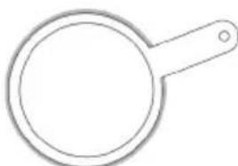
Correct Selection:
Small Pan on Small Element
Large Pan on Large Element
Small Pan on Large Element (with only inner ring of activated)

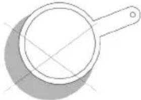
Incorrect Selection:
Small Pan on Large Element
natural_image
Simple line drawing of a magnifying glass (no text or symbols)
Pan Off -Center on Element
natural_image
Simple line drawing of a magnifying glass with handle and lens (no text or symbols)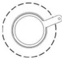
natural_image
Simple line drawing of a magnifying glass inside a dashed circular border (no text or symbols)Cookware
 ARNING ARNING | STORAGE DRAWER |
| WHEN THE OVEN IS IN USE, THE DRAWER MAY BECOME HOT. DO NOT STORE PLASTICS, CLOTH, OR OTHER ITEMS THAT COULD MELT OR BURN IN THE DRAWER. | |
| ⚠ WARNING | OVEN VENT |
| THE OVEN VENT RELEASES HOT AIR AND MOISTURE FROM THE OVEN, IT SHOULD NOT BE BLOCKED OR COVERED. DO NOT SET PLASTICS, PAPER OR OTHER ITEMS THAT COULD MELT OR BURN NEAR THE OVEN VENT. | |
| ⚠ WARNING | CLEANING COOKTOP |
| TO AVOID PERMANENT DAMAGE TO THE COOKTOP SURFACE AND TO MAKE SPILLS EASIER TO REMOVE, CLEAN THE COOKTOP AFTER EACH USE. | |
| ⚠ WARNING | EMPTY COOKWARE |
| DO NOT LEAVE EMPTY COOKWARE ON A HOT SURFACE COOKING AREA, ELEMENT, OR SURFACE BURNER. | |

natural_image
Illustration of a hand measuring a circular object with a ruler, showing rotational motion (no text or symbols)Ideal cookware should have a flat bottom, straight sides and a well fitted lid, and the material should be of medium-to-heavy thickness.
- Rough finishes may scratch the cooktop or grates.
Aluminum and copper may be used as a core or base in cookware.
• Cookware material is a factor in how quickly and evenly heat is transferred, which affects cooking results.
• Cookware with nonstick surfaces should not be used under the broiler. - Check for flatness by placing the straight edge of a ruler across the bottom of the cookware. While you rotate the ruler, no space or light should be visible between it and the cookware.
Use flat-bottomed cookware for best cooking results and energy efficiency. The cookware should be about the same size as the cooking area outlined on the cooktop. Cookware should not extend more than 12 " (1.3 cm) outside the area.
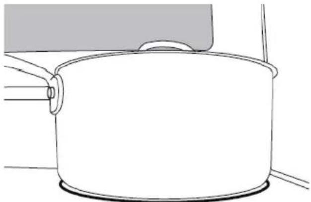
natural_image
Line drawing of a cooking pot with a lid and handle, no text or symbols presentUse the following chart as a general guide for cookware material characteristics. Individual results may vary.
| COOKWARE CHARACTERISTICS | |
| Aluminum | Heats quickly and evenly.Suitable for all types of cooking.Medium or heavy thickness is best for most cooking tasks. |
| Cast iron | Heats slowly and evenly.Good for browning and frying. Maintains heat for slow cooking. |
| Ceramic or Ceramic Glass | Follow manufacturer's instructions.Heats slowly, but unevenly.Ideal results on low to medium heat settings. May scratch the cooktop. |
| Porcelain Enamel-On Steel or Cast Iron | See stainless steel or cast iron. |
| Stainless Steel | Heats quickly, but unevenly.A core/base of aluminum or copper on stainless steel pro-vides even heating. |
Cooktop Indicators:
All Midea ranges are provided with separate indicators alerting the user that the cooktop is in use and that the cooktop surface is hot. Surface-On Indicator: Some models will indicate that a cooktop element is on using a single light on the control panel.
Cooktop Indicators (continued):
Hot Surface Indicator: Some models will have individual indicators for each element under the cooktop glass. Alternatively, other models may only have a single light under the cooktop glass indicating that one or more elements are still hot. The Hot Surface Indicator will illuminate shortly after turning an element on, and it will remain illuminated after the element has been turned off.

NOTE
When the Hot Surface Indicator turns off, the glass surface may still feel slightly hot to the touch. Avoid touching or placing anything on the cooktop until it has completely cooled. The Hot Surface Indicator may illuminate when the cooktop heats up during long baking cycles. This is normal.
Controlling the Cooking Elements:
To turn a cooking element on, push in on the control knob and turn in either direction. The small icon above the control knob indicates the location of the element being controlled. Adjust to the desired heat setting by aligning the power level on the knob to the indicator mark on the control panel. To turn an element off, simply rotate the control knob to the OFF position.
OVEN OPERATION

WARNING
FIRE HAZARD
- Never place anything (aluminum foil, spill mat, baking stone, cookware, etc.) on the bottom of the oven cavity. These items can trap heat or melt, resulting in damage to the appliance and risk of electric shock, smoke, or fire.
- If materials inside the oven should ignite, keep door closed, turn off the appliance, and disconnect the circuit at the circuit breaker box. Wait for the oven to cool before removing contents, cleaning oven, and restoring power.

CAUTION
BURN HAZARD
- Use only dry pot holders or oven mitts when using the oven.
- The oven is vented along the rear of the cooktop and below the control panel. When the oven is in use, this area may get very hot. Do not block or cover the oven vent.

NOTE
FOR BEST EXPERIENCE
- Proper preheating is important for good results. Unless the recipe specifically instructs differently, place food in the oven only after preheating is complete.
- For best results, place food in immediately after preheat beep is sounded.
- Steam or moisture may appear at the oven vent - this is normal.
-
If your model is equipped with a convection fan, it is normal for fan to operate during preheat, even if not in convection baking mode.
-
Do not leave the door open any longer than necessary.
- If in operation, the convection fan will automatically shut off any time door is opened.
- If oven is left in operation for extended periods, it will automatically shut off. Bake modes shut off after 12 hours, Broil will shut off after 12 hour.
CLEANING AND MAINTENANCE

WARNING
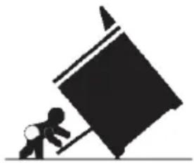
Tip-Over Hazard
- If range is moved for cleaning, servicing, or any other reason, confirm the anti-ti device is engaged per the installation instructions.
- A child or adult can tip the range and be killed.
- Failure to follow these instructions can result in deathor serious burns to children and adults.
natural_image
Silhouette of a person pushing a large tilted object (no text or symbols)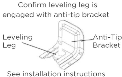
text_image
Confirm leveling leg is engaged with anti-tip bracket Leveling Leg Anti-Tip Bracket See installation instructionsfor details
Glass Cooktop:

CAUTION
LACERATION, SHOCK, BURN, INHALATION HAZARDS
- Glass cooktop is durable, but may break when heated if scratched or otherwise damaged during cleaning. Clean only as described below to avoid glass breakage.
- Clean cook-top with caution - To avoid steam burns, do not use wet sponge or cloth while cooking area is hot. Wear oven mitt if cleaning with razor while cooktop is hot (see special instructions below for sugary spills and melted plastic).
- Some cleaners can produce noxious fumes if applied to a hot surface. Allow cooktop to cool completely before applying any cleaning chemicals.
For best results and prolonged cooktop life, it is recommended to clean the cooktop after each use.
Light soiling:
- Clean with general purpose kitchen cleaner, followed by glass cleaner to remove streaks.
Moderate soiling:
- Commercially available glass cooktop cleaners may be used. Follow instructions on product packaging.
Heavily burned on residue:
- Clean using commercially available glass cooktop cleaner. Follow instructions on product packaging.
- Use a razor blade scraper designed for cleaning glass surfaces. Ensure razor is clean and new to minimize risk of scratching cooktop.
- Hold razor at approximately 45° angle, apply firm pressure, and smoothly press razor through residue.
• After heavy residue is removed, clean again using glass cooktop cleaner compound.
Sugary spills/plastic - Sugary spills and melted plastics may cause damage the cooktop not covered by warranty if not removed immediately.
- Turn off all cooktop heating elements and remove all cookware from cooktop.
- As described above, use a clean, new razor blade scrape and wear oven mitt for protection to quickly remove sugary spills or melted plastic from cooktop glass while cooktop is hot.
- Quickly wipe removed material away from hot cooktop heating element using dry paper towel.
- Wait until the cooktop glass has completely cooled before attempting a more thorough cleaning as described above.
Control Panel:

CAUTION
ELECTRIC SHOCK HAZARD
- Do not use excessive amounts of water or cleaners to clean knob areas. If moisture is forced into openings behind knobs, there is a potential for electric shocks.
- Avoid spraying kitchen cleaners directly into the openings behind knobs.
TO PREVENT COSMETIC DAMAGE
Do not use scouring pads, abrasive cleaners, strong liquid chemicals, steel wool, or oven cleaners, as these may damage the control panel finish.
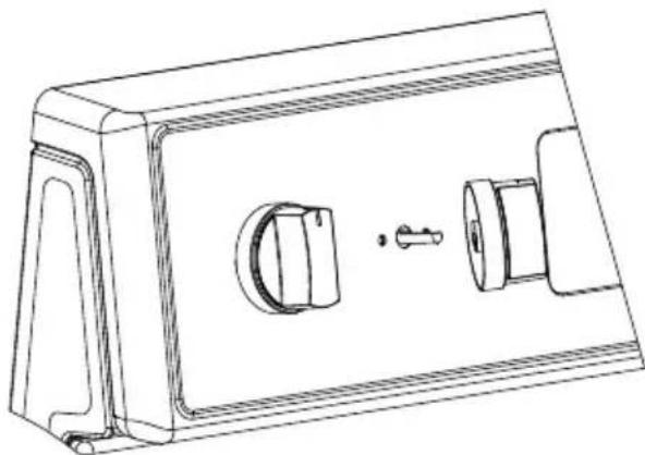
For best results, it is recommended to clean the user interface and control panel after each use. Control knobs can be removed for easier cleaning. Ensure knobs are in the "OFF" position before removing. Pull straight back with a firm pressure to remove knob from stem. Clean entire panel with a lightly damp soft cloth using mild soap and water. Glass cleaner can be used on oven control to remove streaks. Stainless steel cleaner can be used on the exposed metal to remove streaks. Knobs should be washed by hand in warm soapy water - do not wash in dishwasher. Wait until knobs are dry before placing back on stem. Be sure to align profile in knob to stem shape to ensure smooth fit and avoid damage to knob or control.
natural_image
Technical line drawing of a mechanical housing or enclosure with internal components and a handle (no text or symbols)Oven Interior:

CAUTION
BURN HAZARD
- Oven surfaces - especially oven bottom - may be hot. Use caution to avoid contact with hot surfaces.
- Hot surfaces may create hot steam in wet sponge or cloth while cleaning. If steam is evident when wiping out oven, wait until oven has cooled.
Check oven after each use to determine if any spills or splattering occurred that require cleaning. Wipe out oven interior with a lightly damp soft cloth using mild soap and water to remove light spills.
Oven Lights:

CAUTION
SHOCK, BURN, AND LACERATION HAZARDS
- Disconnect power to oven and wait until oven is cool before attempting to service light bulbs.
- Handle glass cover carefully to reduce risk of breakage. If lamp cover is difficult to remove, do not force. Contact a qualified service provider for repairs.
- Do not operate oven without glass cover in place.
The ovens light is a standard 25-watt (G9 Halogen) appliance bulb. Before replacing, make sure the oven and cooktop are cool and the control knobs are off.
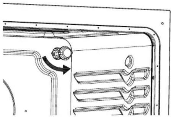
HOW TO REPLACE OVEN LIGHT
- Disconnect the power supply.
- Turn the glass cover counter clockwise to remove.
- Pull out the bulb straight out of the socket.
- Replace bulb by pushing in, then reinsert glass cover clockwise
- Reconnect power.
natural_image
Technical line drawing of a mechanical component with curved internal structure and directional arrow (no text or symbols)CLEANING METHOD FOR STAINLESS STEEL
- Use a stainless-steel cleaner or a mild cleaner recommended on stainless-steel surfaces.
- Wipe cleaner with a soft cloth in the direction of the grain to avoid damage.
- Remove any excess with a clean and dry, lint-free cloth.
CLEANING THE OVEN DOOR EXTERIOR
- Clean with a mild soap and warm water.
- Wipe clean with a dry soft cloth.
TROUBLESHOOTING
Read before calling for service
Midea is committed to providing you with a quality appliance that works as expected. If you find something that is not working as anticipated, check the table below for helpful hints and advice that might save you the time and expense of calling for repair.
| OVEN WILL NOT OPERATE POSSIBLE SOLUTIONS | |
| Has a household fuse blown, or has a circuit breaker tripped? | Replace the fuse or reset the circuit breaker. If the problem continues, call an electrician. |
| Is the Electronic Oven Control set correctly? | See “Electronic Oven Controls” section. |
| Display shows “E02” | Temperature sensor error. Call Customer Service. |
| Display shows “E03” | High temperature warning. Oven function will shut off automatically. Allow oven to cool for 30 minutes and resume using oven functions. If error continues to occur call Customer Service. |
| Is the Oven Control Lockout set? | See “Control Lockout” section. |
| OVEN TEMPERATURE TOO HIGH OR TOO LOW | POSSIBLE SOLUTIONS |
| Does the Oven Temperature Calibration need adjustment? | • See “Oven Temperature Control” section. |
| Do the Oven Indicator Lights flash? | • See the “Display” and/or the “Oven Lights” section. If the indicator light(s) keeps flashing, call for service. |
| OVEN COOKING RESULTS NOT WHAT EXPECTED | POSSIBLE SOLUTIONS |
| Is the proper oven temperature calibration set? | • See “Oven Temperature Control” section. |
| Was the Oven preheated? • See “Baking” section. | |
| Are the racks positioned properly? | • See “Positioning Racks and Bakeware” section. |
| Is there proper air circulation around bakeware? | • See “Positioning Racks and Bakeware” section. |
| Is the batter evenly distributed in the pan? | • Check that batter is level in the pan. |
| Is the proper length of time being used? | • Adjust cooking time. |
| Has the oven door been opened while cooking? | • Oven peeking releases oven heat and can result in longer cooking times. |
| Are baked items too brown on the bottom? | • Move rack to higher position in the oven. |
| Are pie crust edges browning early? | • Use aluminum foil to cover the edge of the crust and/or reduce backing temperature. |
2 YEAR LIMITED WARRANTY
This warranty is provided to the original purchaser at retail (the "Purchaser" or "you") by Midea America Corp. ("Midea" or "we"), which warrants all parts of this Product, as described below. Midea warrants this Product to the Purchaser for personal, family or household use. This warranty covers performance and quality issues in materials and workmanship that appear under normal use and maintenance appearing within two years from the date of purchase. This warranty gives you specific rights, and you may also have other rights that vary from state to state.
WARRANTY LIMITATIONS
This warranty is given only to the original purchaser at retail in either the United States or Canada and may not be transferred to any subsequent buyer. This warranty does not apply to purchasers of our products for use or resale in a business; a separate commercial warranty may protect those purchasers.
This warranty does not cover any Product failure caused by:
(a) Abuse, damage or use of the Product in violation of the Product instructions.
(b) Modification to any Product or part.
(c) Failure to maintain the Product or part as described in accordance with the Product instructions.
(d) Faulty installation or application.
(e) Use of parts or accessories not compatible with this Product.
(f) Floods, fires, winds, lightning, accidents, corrosive atmosphere, or other conditions beyond Midea's control.
(g) Interruption in electrical service or inadequate electrical service.
(h) Replacement of fuses and replacement or resetting of circuit breakers.
(i) Frozen or broken water pipes, water damage, moisture intrusion, mold or other biological growth.
(j) The use, combination or linking of the Product to other products, processes or materials not provided by Midea.
WARRANTY REMEDY
If any quality or performance issue covered by this warranty is discovered during the warranty period, we will, at our option, repair or replace any such Product. This warranty is limited to Product repair or replacement by an authorized Midea servicer or dealer and does not cover any shipping cost, labor cost, customs duties, inland logistics cost, or cost of service, including any diagnostics, removal, transportation, or reinstallation costs. If we ask, you must return the Product to us.
WARRANTY DISCLAIMER; EXCLUSION OF DAMAGES
This is the only express warranty to consumers that we offer on our Products. ANY IMPLIED WARRANTIES BY MIDEA, INCLUDING BUT NOT LIMITED TO WARRANTIES OF MERCHANTABILITY AND FITNESS FOR PARTICULAR PURPOSE, ARE LIMITED TO THE DURATION OF THIS EXPRESS WARRANTY. Some states and provinces do not allow the exclusion of express warranties and/or limitations on how long an implied warranty lasts, so the above exclusion and/or limitation may not apply to you.
THE REMEDY DESCRIBED ABOVE IS THE ONLY ONE THAT WE WILL PROVIDE, EITHER UNDER THIS WARRANTY OR UNDER ANY WARRANTY ARISING BY OPERATION OF LAW. WE WILL NOT BE RESPONSIBLE FOR ANY CONSEQUENTIAL OR INCIDENTAL DAMAGES ARISING FROM THE BREACH OF THIS WARRANTY OR ANY OTHER WARRANTY, WHETHER EXPRESS OR IMPLIED, NEGLIGENCE OR OTHER TORT, OR ON ANY STRICT LIABILITY THEORY, INCLUDING BUT NOT LIMITED TO LOST PROFITS. Some states do not allow the exclusion or limitation of incidental or consequential damages, so the above exclusion may not apply to you.
WARRANTY CLAIMS PROCESS
For more information or to make a warranty claim, please visit:
https://www.midea.com/us/support
Or contact us at:
Telephone: 1-866-646-4332
Email: customerserviceusa@midea.com
You must have Your bill of sale, delivery slip, or appropriate proof of purchase to submit a warranty claim. The date of purchase establishes the warranty period, should service be required.
DISPUTE RESOLUTION
ARBITRATION CLAUSE. IMPORTANT. PLEASE REVIEW THIS ARBITRATION CLAUSE. IT AFFECTS YOUR LEGAL RIGHTS.
(a) Parties: This arbitration clause (this "Arbitration Clause") affects your rights against Midea and any of its affiliates or employees or agents, successors, or assigns, all of whom together are referred to below as "we" or "us" for ease of reference.
(b) ARBITRATION REQUIREMENT: EXCEPT AS STATED BELOW, ANY DISPUTE BETWEEN YOU AND ANY OF US SHALL BE DECIDED BY NEUTRAL, BINDING ARBITRATION RATHER THAN IN COURT OR BY JURY TRIAL. "Dispute" will be given the broadest possible meaning allowable by law. It includes any dispute, claim, or controversy arising from or relating to your purchase of this Product, any warranty upon the Product, or the Product's condition. It also includes determination of the scope or applicability of this Arbitration Clause. The arbitration requirement applies to claims in contract and tort, pursuant to statute, or otherwise.
(c) CLASS-ARBITRATION WAIVER: ARBITRATION IS HANDLED ON AN INDIVIDUAL BASIS. IF A DISPUTE IS ARBITRATED, YOU AND WE EXPRESSLY WAIVE ANY RIGHT TO PARTICIPATE AS A CLASS REPRESENTATIVE OR CLASS MEMBER ON ANY CLASS CLAIM YOU MAY HAVE AGAINST US OR WE AGAINST YOU, OR AS A PRIVATE ATTORNEY GENERAL OR IN ANY OTHER REPRESENTATIVE CAPACITY, TO THE MAXIMUM EXTENT PERMITTED BY LAW. YOU AND WE ALSO WAIVE ANY RIGHT TO CLASS ARBITRATION OR ANY CONSOLIDATION OF INDIVIDUAL ARBITRATIONS.
(d) Discovery and Other Rights: Discovery and rights to appeal in arbitration are generally more limited than in a lawsuit. This applies to both you and us. Other rights that you or we would have in court may not be available in arbitration. Please read this Arbitration Clause and consult the rules of the arbitration organizations listed below for more information.
(e) SMALL CLAIMS COURT OPTION: YOU MAY CHOOSE TO LITIGATE ANY DISPUTE BETWEEN YOU AND ANY OF US IN SMALL CLAIMS COURT, RATHER THAN IN ARBITRATION, IF THE DISPUTE MEETS ALL REQUIREMENTS TO BE HEARD IN SMALL CLAIMS COURT.
(f) Governing Law: For residents of the United States, the procedures and effect of the arbitration will be governed by the Federal Arbitration Act (9 U.S.C. § 1 et seq.) rather than by state law concerning arbitration. For residents of Canada, the procedures and effect of the arbitration will be governed by the applicable arbitration law of the province in which you purchased your Product. The law governing your substantive warranty rights and other claims will be the law of the state or province in which you purchased your Product. Any court having jurisdiction may enter judgment on the arbitration award.
4867-9660-6836.6
(g) Rules of the Arbitration: If the amount in controversy is less than \250,000, the arbitration will be decided by a single arbitrator. If the amount in controversy is greater than or equal to \250,000, the arbitration will be decided by a panel of three arbitrators. The arbitrator(s) will be chosen pursuant to the rules of the administering arbitration organization. United States residents may choose JAMS (1920 Main Street, Ste. 300, Irvine, CA 92614, www.jamsadr.com), or, subject to our approval, any other arbitration organization. In addition, Canadian residents may choose the ADR Institute of Canada (234 Eglinton Ave. East, Suite 405, Toronto, Ontario, M4P 1K5, www.amic.org). These organizations' rules can be obtained by contacting the organization or visiting its website. If the chosen arbitration organization's rules conflict with this Arbitration Clause, the provisions of this Arbitration Clause control. The award of the arbitrator(s) shall be final and binding on all parties.
(h) Location of the Arbitration Hearing: Unless applicable law provides otherwise, the arbitration hearing for United States residents will be conducted in the federal judicial district in which you reside (in your hometown area) or, for Canadian residents, in the province in which you reside, and, if you choose, will be in-person.
(i) Costs of the Arbitration: Each party is responsible for its own attorney, expert, and other costs and fees unless applicable law requires otherwise. Notwithstanding the preceding sentence, and unless applicable law requires otherwise, if you are a consumer under the JAMS rules or the rules of another agreed upon arbitration administrator, Midea will pay or reimburse you for all reasonable fees or costs to the extent required by law or the applicable arbitration administrator's rules. Whether or not required by law or such rules, if you prevail at arbitration on any claim against Midea, Midea will reimburse you for any reasonable fees paid to the arbitration administrator in connection with the arbitration proceedings. Under no circumstances will Midea seek from you payment or reimbursement of any reasonable fees that Midea incurs in connection with the arbitration. If you are required to advance any fees or costs to JAMS or other agreed upon arbitration administrator, but you ask Midea to do so in your stead, Midea will consider and respond to your request.
(j) Survival and Enforceability of this Arbitration Clause: This Arbitration Clause shall survive the expiration or termination, or any transfer, of the warranty on your Product. If any part of this Arbitration Clause, except waivers of class-action rights, is found to be unenforceable for any reason, the remainder of this clause and the warranty shall remain enforceable. If, in a case in which class-action allegations have been made, the waiver of class-action rights under this warranty is found to be unenforceable with respect to any part of the dispute, the parts of the dispute as to which the waiver of class-action rights have been found unenforceable will be severed and will proceed in court without reference or application of this Arbitration Clause. Any remaining parts will proceed in arbitration.
QUEBEC RESIDENTS
The arbitration provisions of this warranty shall not apply to residents of Quebec.
TRADEMARKS, COPYRIGHTS AND LEGAL STATEMENT
Midea logo, word marks, trade name, trade dress and all versions thereof are valuable assets of Midea Group and/or its affiliates ("Midea"). to which Midea owns trademarks, copyrights and other intellectual property rights, and all goodwill derived from using any part of an Midea trademark. Use of Midea trademark for commercial purposes without the prior written consent of Midea may constitute trademark infringement or unfair competition in violation of relevant laws.
This manual is created by Midea and Midea reserves all copyrights thereof. No entity or individual may use, duplicate, modify, distribute in whole or in part this manual, or bundle or sell with other products without the prior written consent of Midea.
All the described functions and instructions were up to date at the time of printing this manual. However, the actual product may vary due to improved functions and designs.
DATA PROTECTION NOTICE
For the provision of the services agreed with the customer,
we agree to comply without restriction with all stipulations of applicable data protection law, in line with agreed countries within which services to the customer will be delivered.
Generally, our data processing is to fulfil our obligation under contract with you and for product safety reasons, to safeguard your rights in connection with warranty and product registration questions. In some cases, but only if appropriate data protection is ensured, personal data might be transferred to recipients located outside of the European Economic Area.
Further information are provided on request. You can contact our Data Protection Officer via MideaDPO@midea.com. To exercise your rights such as right to object your personal date being processed for direct marketing purposes, please contact us via MideaDPO@midea.com. To find further information, please follow the QR Code.

text_image
Mideamake yourself at home
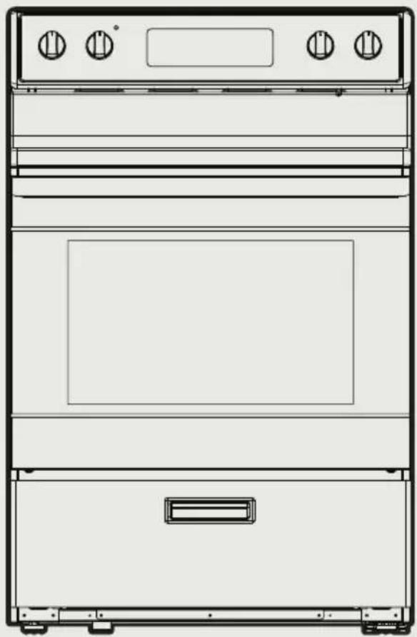
natural_image
Line drawing of a double oven with front panel and side door (no text or symbols)GAMME ÉLECTRIQUE MÉNAGE
MANUEL DE L'UTILISATEUR
MER30B12AWWC
MER30B12ASSC
INSTALLATION DU PRODUIT FR-16
INSTRUCTIONS D'UTILISATION FR-35
NETTOYAGE ET ENTRETIEN FR-50
DÉPANNAGE FR-54
MARQUES COMMERCIALES, DROITS
D'AUTEUR ET MENTIONS LÉGALES FR-59
AVIS DE PROTECTION DES DONNÉES FR-60
CONSIGNES DE SÉCURITÉ
DEFINITIONS DE SECURITE
natural_image
Silhouette of a person pushing a large object on a flat surface (no text or symbols)Support anti- basculement
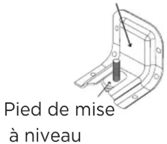
natural_image
Line drawing of a front-mounted appliance with four control knobs and a handle, showing no text or symbols.SPÉCIFICATION
MODÈLE MER30B12AWWC
/MER30B12ASSC
SOURCE DE COURANT
120/240 V\~60 Hz - 9.65 kW
120/208 V\~ 60 Hz - 7.238 kW
DIMENSIONS DU PRODUIT
text_image
Technical diagram of an oven with labeled parts A, B, C, D, and E for identification.PRÉSENTATION DU PRODUIT
text_image
A B C K D J E F G H L Inatural_image
Technical line drawing of a mechanical assembly with a drawer and metal frame (no text or symbols)INSTALLATION DU PRODUIT
natural_image
Line drawing of a flexible electrical plug with multiple wires and a separate terminal socket (no text or symbols)natural_image
Line drawing of an electric shock absorber with a terminal plug and socket (no text or symbols)14-50P GETWIREDUSA FX359
natural_image
Technical line drawing of a threaded bolt or connector (no text or symbols)natural_image
Technical line drawing of two bolted fasteners with hexagonal nuts (no text or symbols)natural_image
Line drawings of four different types of gloves and footwear: gloves, shoes, and goggles (no text or symbols)natural_image
Line drawing of two folded paper sheets (no text or symbols)natural_image
Simple line drawing of a pencil resting on a rectangular sheet (no text or symbols)natural_image
Line drawing of a drill press and a cylindrical tool (no text or symbols)natural_image
Line drawing of a pair of pliers (no text or symbols)LACÉRATION, OBJET ÉTRANGER, RISQUE D'ÉCRASEMENT
text_image
A B C D E F G H I J K Lnatural_image
Technical line drawing of a plug and socket (no text or symbols)INSTRUCTIONS POUR LE CORDON D'ALIMENTATION A 3 BROCHES
natural_image
Technical line drawing of a mechanical component with mounting base and clamping bracket (no text or symbols)natural_image
Diagram of a door handle mechanism with a bracket and arrow indicating movement (no text or symbols)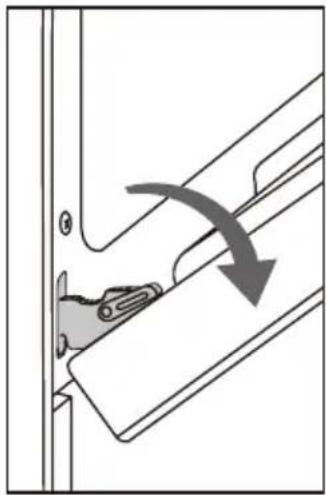
natural_image
Diagram of a door hinge mechanism with a curved arrow indicating rotation (no text or symbols present)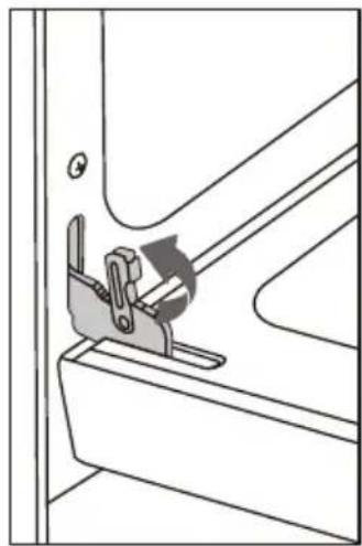
natural_image
Technical line drawing of a mechanical clamp or bracket assembly (no text or symbols)natural_image
Technical line drawing of a mechanical device with a drawer and metal frame (no text or symbols)Plage de niveaux
natural_image
Technical line drawing of a mechanical assembly with ribbed and mounting components (no text or symbols)natural_image
Technical line drawing of a vehicle door frame with internal compartments and mounting brackets (no text or symbols)INSTRUCTIONS D'UTILISATION
natural_image
Technical line drawing of a mechanical component with a grid-like structure and an arrow indicating rotation (no text or symbols)natural_image
Technical line drawing of a mechanical component with internal structure and directional arrow (no text or symbols)Positions de la Grille:
natural_image
Line drawing of four rectangular crackers arranged on a grid-lined baking tray (no text or symbols)natural_image
Line drawing of four rectangular crackers placed on a grid-lined rack (no text or symbols)
REMARQUE
natural_image
Simple line drawing of a magnifying glass (no text or symbols)natural_image
Simple line drawing of a magnifying glass with a diagonal line crossing over it, no text or symbols present.natural_image
Illustration of a hand measuring a circular object with a ruler, showing rotational motion (no text or symbols)natural_image
Line drawing of a cooking pot with a lid and handle (no text or symbols)natural_image
Silhouette of a person pushing a large block with a stick (no text or symbols)RISQUES DE DÉCOLORATION, D'ÉLECTROCUTION, DE BRÛLURE ET D'INHALATION
natural_image
Technical line drawing of a mechanical housing component with internal components and mounting holes (no text or symbols)
MISE EN GARDE
RISQUE DE BRÛLURE
COMMENT REMPLACER LA LAMPE DU FOUR
natural_image
Technical line drawing of a vehicle air duct system with pipe routing and valve components (no text or labels)METHODE DE NETTOYAGE DE L'ACIER INOXYDABLE
https://www.midea.com/us/support
make yourself at home