
MER30S2ABB - Cooker MIDEA - Free user manual and instructions
Find the device manual for free MER30S2ABB MIDEA in PDF.

| Product Type | Freestanding Electric Range |
| Brand | Midea |
| Model | MER30S2ABB |
| Color | Black |
| Overall Dimensions (H × W × D) | 46 1/4 × 29 7/8 × 26 15/16 inches (1174 × 759 × 685 mm) |
| Cooktop Height | 36 inches (91.4 cm) |
| Net Weight | 78 kg (172 lb) |
| Oven Capacity | 6.3 ft³ (178 L) |
| Rated Voltage | 120/208 V AC, 40 A or 120/240 V AC, 50 A |
| Total Power | 7240 W (208 V) / 9640 W (240 V) |
| Cooktop Surface Type | Ceramic Glass with Radiant Elements |
| Number of Burners | 4 |
| Oven Functions | Bake, Broil, Timer, Light, Control Lock, Sabbath Mode |
| Controls | Rotary knobs for cooktop, electronic panel for oven |
| Display | Digital LED |
| Oven Door | Removable for cleaning and installation |
| Storage Drawer | Yes, removable |
| Safety | Anti-tip bracket, control lock, hot surface indicator |
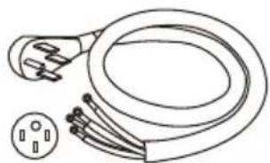
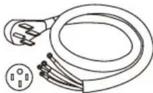
| Power Supply | 4-prong power cord (50 A) provided (Canada) or direct connection (USA) |
| Electrical Installation | Requires single-phase 208/240 V, 60 Hz, individual circuit protected by 40/50 A breaker |
| Surface Material | Ceramic Glass |
| Cleaning | Manual: do not use self-cleaning oven cleaner |
| Warranty | 2 years limited (parts and labor) |
Frequently Asked Questions - MER30S2ABB MIDEA
User questions about MER30S2ABB MIDEA
0 question about this device. Answer the ones you know or ask your own.
Ask a new question about this device
Download the instructions for your Cooker in PDF format for free! Find your manual MER30S2ABB - MIDEA and take your electronic device back in hand. On this page are published all the documents necessary for the use of your device. MER30S2ABB by MIDEA.
USER MANUAL MER30S2ABB MIDEA
natural_image
Line drawing of a standard open-plan electric stove with four circular vented outlets (no text or symbols)ELECTRIC RANGE
INSTALLATION INSTRUCTION
MER30S2AST/MER30S2AWW/MER30S2ABB
THANK YOU LETTER
Thank you for choosing Midea! Before using your new Midea product, please read this manual thoroughly to ensure that you know how to operate the features and functions that your new appliance offers in a safe way.
CONTENTS
THANK YOU LETTER----EN-01
IMPORTANT SAFETY INSTRUCTIONS ----EN-02
PRODUCT INSTALLATION ----EN-08
TROUBLESHOOTING ----EN-25
TRADEMARKS, COPYRIGHTS AND LEGAL STATEMENT --EN-31
DATA PROTECTION NOTICE----EN-32
IMPORTANT SAFETY INSTRUCTIONS
Intended Use
The following safety guidelines are intended to prevent unforeseen risks or damage from unsafe or incorrect operation of the appliance. Please check the packaging and appliance on arrival to make sure everything is intact to ensure safe operation. If you find any damage, please contact the retailer or dealer. Please note modifications or alterations to the appliance are not allowed for your safety concern. Unintended use may cause hazards and loss of warranty claims.
Explanation of Symbols
 | DangerThis symbol indicates that there are dangers to the life and health of persons due to extremely flammable gas. |
 | Warning of electrical voltageThis symbol indicates that there is a danger to life and health of persons due to voltage. |
 | WarningThe signal word indicates a hazard with a medium level of risk which, if not avoided, may result in death or serious injury. |
 | CautionThe signal word indicates a hazard with a low degree of risk which, if not avoided, may result in minor or moderate injury. |
 | AttentionThe signal word indicates important information (e.g. damage to property), but not danger. |
 | Observe instructionsThis symbol indicates that a service technician should only operate and maintain this appliance in accordance with the operating instructions. |
Read these operating instructions carefully and attentively before using/commissioning the unit and keep them in the immediate vicinity of the installation site or unit for later use!
WARNING TIP OVER HAZARD
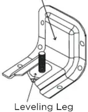
A child or adult can tip the range and be killed. Verify the anti-tip device has been properly installed and engaged per installation instructions. Ensure the anti-tip device is re-engaged when the range is moved. Do not operate the range without the anti-tip device in place and engaged. Failure to do so can result in death or serious burns to children or adults. Do not remove the leveling legs. Doing so will prevent the range from being secured by the anti-tip device.
To confirm the anti-tip bracket is properly installed, look underneath the range to confirm rear leveling leg is engaged in the bracket. If visual inspection is not possible:
- Slide range forward
- Confirm anti-tip bracket is securely attached to floor or wall in correct position according to installation instructions.
- Fully slide the range back against the wall so that leveling leg engages with anti-tip bracket.
If range is removed from service, secure door closed or remove door to minimize tip over risk. (See "Door" section under "Cleaning and Maintenance" in this manual for instructions on how to remove door.)

natural_image
Technical line drawing of a mechanical bracket with a cylindrical component and mounting holes (no text or symbols)WARNING
INSTALLATION AND MAINTENANCE
- This appliance is intended for normal residential use. It is not approved for commercial use, outdoor installation, or any other application not specifically allowed by this manual.
- Be sure your appliance is properly installed and grounded by a qualified service provider.
- Installer shall leave all instructions, including this manual, conversion instructions, and anti-tip bracket instructions, with the owner/resident, with directions to retain for future reference.
- Do not operate this appliance if it has been damaged or is not working properly. Contact a qualified service provider for repairs.
- Do not repair or replace any part of the appliance unless specifically recommended in the manual. All other servicing should be referred to a qualified service provider.
- Do not use oven cleaners. No commercial oven cleaner or oven liner protective coating of any kind should be used with any part of this appliance.
- This appliance requires connection to a 3-prong or 4-prong, 240VAC split-phase, 60Hz grounded electrical source. When installed, appliance must be electrically grounded in accordance with local codes or, in the absence of local codes, with the National Electrical Code, NFPA 70 or the Canadian Electric Code, CSA C22.1-02.
WARNING
GENERAL USAGE
- Do not store any flammable materials or temperature sensitive items inside oven, in storage drawer, or on top or near cooktop heating elements of the appliance.
- Do not allow anyone to climb, stand, lean, sit, or hang on any part of an appliance, especially a door or drawer.
- This appliance has not been evaluated for use with any 3rd party after-market systems.
WARNING
COOKTOP HAZARD
- Do not cook on a broken glass cooktop - If cooktop should break, cleaning solutions and spillovers may penetrate the broken cooktop and create a risk of electric shock. Contact a qualified service provider immediately for repairs.
- In the event that personal clothing or hair catches fire, drop and roll immediately to extinguish flames.
WARNING
OVEN HAZARDS
- Never place anything (aluminum foil, spill mat, baking stone, cookware, etc.) on the bottom of the oven cavity. These items can trap heat or melt, resulting in damage to the appliance and risk of electric shock, smoke, or fire.
- Do not obstruct oven vents or any other slots or openings on the unit.
BEFORE STARTING INSTALLATION
Parts Included with Product
Packed with the product are the following oven components and accessories. When product is first unpacked, verify that all these components are present. If anything is missing, check the packaging materials carefully for missing items. If items cannot be located, contact Midea customer service at 1-866-646-4332 or visit midea.com/us/support for assistance.
Anti-Tip Bracket Kit
Wire Rack Owner's Manual
natural_image
Line drawing of an electric shock absorber with a terminal plug and socket (no text or symbols)4-prong 240VAC
Power Cord, Rated 50A (Products sold in Canada only)
Materials Needed:
The utility connection and house structure at each home may be different, so the specific parts required for connection to the house are not included with the product. The parts identified below are or may be required to complete the installation. Always use new components - never use an old part for new range installation.
natural_image
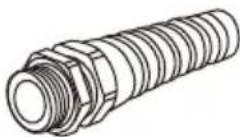
Line drawing of a multi-pin electrical plug and its cable (no text or symbols)14-50P GETWIREDUSA
FX359
(not applicable to products sold in Canada - these are provided with power cord)
Strain Relief for Power Cord (supplied with cord kit)
natural_image
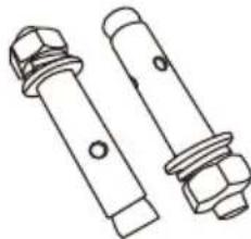
Technical line drawing of two bolted fasteners with hexagonal nuts (no text or symbols)5/16" OD Sleeve Anchor (with 1/4" bolt) - 2 pcs (for concrete floors only)
Tools Needed:
To complete the installation, have the following tools readily available:
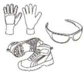
natural_image
Line drawings of four common footwear and accessories: gloves, shoes, and goggles (no text or symbols)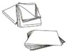
natural_image
Illustration of two folded paper sheets, one open and one filled with blank pages (no text or symbols)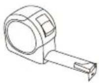
Cut Resistant Gloves, Safety Glasses or Goggles, and Steel-Toed Shoes (for your safety and protection)
Drop Cloth or Cardboard (optional - to protect floor)
Tape Measure (to confirm installation space)
natural_image
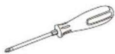
Simple line drawing of a pencil and ruler on a rectangular base (no text or symbols)Phillips Screwdriver (to access serviceable covers)
Nut Driver (for electrical connections)
Pencil and Ruler (for anti-tip bracket installation)
natural_image
Line drawing of a drill press and a cylindrical tool (no text or symbols)
natural_image
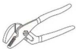
Line drawing of a pair of pliers (no text or symbols)Drill and 1/8" Drill Bit (for anti-tip bracket installation)
Masonry Drill Bit (for anti-tip bracket installation - concrete floors only)
Adjustable Groove - Joint or Gooseneck Pliers (for leveling product)

Level (for leveling product)
PRODUCT INSTALLATION
Remove Old Appliance
WARNING
FIRE, EXPLOSION HAZARD
- Installation and service must be performed by a qualified installer or service agency.
CAUTION
LACERATION, FOREIGN OBJECT, CRUSH HAZARD
- When installing, moving, or servicing any appliance, wear proper protective equipment, including cut resistant gloves, steel-toed shoes, and safety glasses.
If the new range is replacing an existing installation, first remove the old appliance.
Directions:
- Shut off the electrical supply to the range at the breaker box or fuse box. Leave it off until the installation has been completed.
- Move appliance to access the electrical connections.
- Disconnect electrical connections and move appliance out of and away from installation space.
Electrical Supply Requirements
WARNING
ELECTRICAL SHOCK HAZARD
- Installation must be electrically grounded in accordance with local codes or, in the absence of local codes, with the National Electrical Code, NFPA 70 or the Canadian Electric Code, CSA C22.1-O2.
Clearances and Dimensions:
IMPORTANT
TO PREVENT DAMAGE TO CABINETS
- This range has been designed to comply with the maximum allowable wood cabinet temperature of 194 °F (90 °C). Make sure the wall coverings, countertops, cabinets, and any other materials in contact with the range are rated for a minimum of 194 °F (90 °C). If not, discoloration, delamination, or melting may occur.
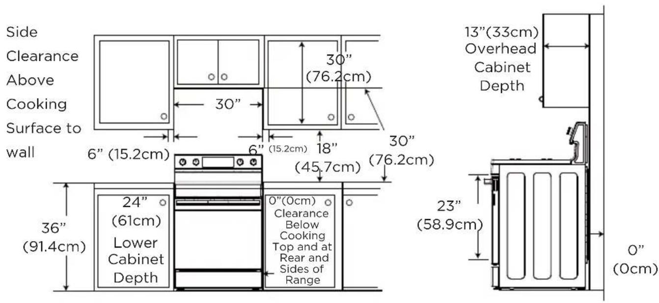
Before starting the installation process, confirm the installation space meets the following dimensions and clearances. Do not locate the range where it may be subject to strong drafts - seal any openings in the wall, floor, or cabinets in the installation space. Provide adequate clearances between the range and adjacent combustible surfaces. These dimensions must be met for safe use of the range. The given dimensions provide minimum clearance. Contact surface must be solid and level.
The minimum clearance is 0" for the rear of the range. Follow all dimension requirements to prevent property damage, potential fire hazard, and incorrect countertop and cabinet cuts.
Countertop surfaces immediately around installation space must be flat and level for proper installation.
When the floor covering (hardwood flooring, tile, carpet, etc.) ends at the front of the range, the area that the range will be installed on must be built up with plywood to the same level or higher than the floor covering. This will allow the range to be moved for cleaning and servicing, as well as provide proper air flow to the range.
Ensure floor covering material can resist temperatures of at least 167^ (75°C). Ensure the wall coverings, countertops, cabinets, and any other materials in contact with the range can resist the heat generated up to 194^ (90°C) by the range.
FREESTANDING CUTOUT
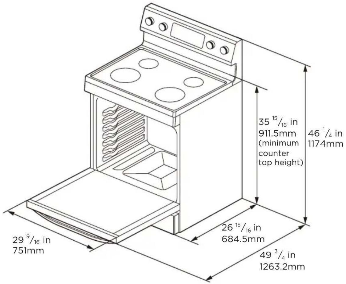
Product Specifications
| Description Electric Free Standing Oven | |
| Voltage 120/208VAC 40Amp 120/240VAC 50Amp | |
| Electric power 7240W 9640W | |
| Exterior Dimensions 46 ^1/_4 H x 29 ^7/_8 W x 26 ^15/_16 D | |
| Height to Cooking Surface in 36" (91.4cm) | |
| Net Weight 78kg (172 lbs) | |
| Oven Capacity 6.3 cu. ft. | |
| Power Ratings Refer to rating plate label | |
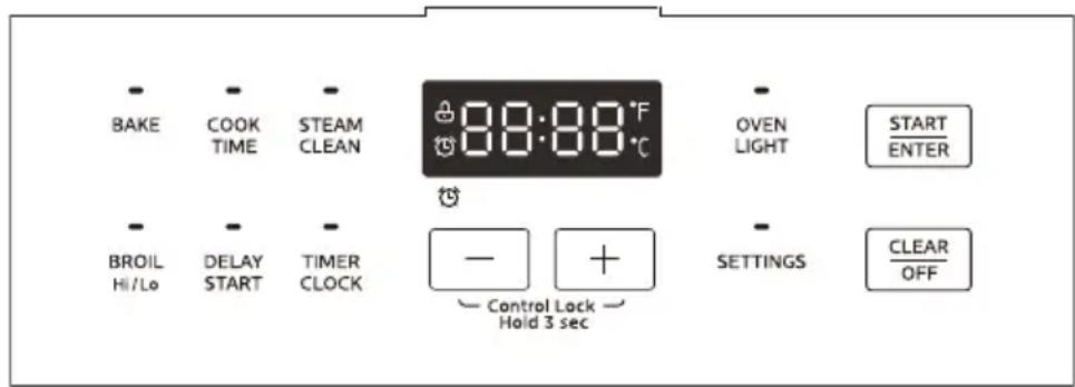
Range Overview
- Cooktop Knob
- Control Panel
- Ceramic Glass Surface
- Door Hinge (each side)
-
Door
-
Door Handle
- Adjustable Feet
- Oven Light
- Door Gasket
-
Rack Positions
-
Oven Bottom
- Storage Drawer
Rating Plate Label Location
The rating plate label contains appliance certification, rating, and identification information. The model and serial number from the rating plate label is needed to register the product, order replacement parts, or when contacting customer service. The rating plate label is located in the cavity front frame on either the left or right side panel.
installation Procedure
Packaging Removal:
IMPORTANT
TO PREVENT DAMAGE TO APPLIANCE
- Failure to remove packaging materials could result in damage to the appliance.
Remove all tape and packaging materials. Check for film on stainless steel parts, padding/spacers on and around door and face of oven, cardboard and plastic on and around racks, inside storage drawer, etc. Do not use sharp instruments, rubbing alcohol, flammable fluids, or abrasive cleaners to remove tape or glue. These products can damage the surface of your range.
Inventory all loose parts against the "Parts Supplied" list.
Check for shipping damage and/or missing parts. Any damage and/or missing parts should be reported to your local retailer.
To reduce the weight of the range while being moved, adjusted, and installed, leave the any other accessories to the side until they are ready to be installed later in these instructions.
Door Removal and Reinstallation:

WARNING
FIRE HAZARD
- If door is removed, confirm that door operates correctly and seals properly when reinstalled. If door gasket does not seal completely, heat escaping from around doors could ignite cabinetry.
During installation, service, and leveling, it may be easier to perform the necessary work if the oven door is removed. This makes the appliance lighter and access to the oven cavity easier. Follow these instructions below to remove and reinstall the door.
Door can be removed for easier cleaning, servicing, or installation:
- Opendoorfully.
- On each door hinge, flip down the lock mechanism so that it engages with the door when the door is rotated towards being closed.
- Once both lock mechanisms are engaged, continue to rotate do until \~2-3 inches from being fully closed.
- Grasp door firmly from the sides and lift door up and out from oven face. Do not lift door by door handle to reduce risk of broken door glass.
natural_image
Diagram of a door handle with a clip and arrow indicating rotation (no text or symbols)
natural_image
Diagram of a door handle mechanism with an arrow indicating clockwise motion (no text or symbols)
natural_image
Technical diagram of a door handle assembly with a black arrow indicating direction (no text or symbols present)Reinstalling Door
- Holding door from the sides, align door so that hinges slip back into openings.
- Rotate door until -2-3 inches from being fully closed, allow door to drop into notches on hinges.
- Rotate door out until fully open.
- Flip the hinge locking mechanism back up and away from the door.
- Check that door opens and closes correctly.
- If door does not operate correctly, re-engage locking mechanisms, remove door, and reattempt installation.
natural_image
Technical line drawing of a door handle assembly with a bracket and mounting bracket (no text or symbols)
natural_image
Diagram of a door hinge mechanism with a curved arrow indicating rotation (no text or symbols present)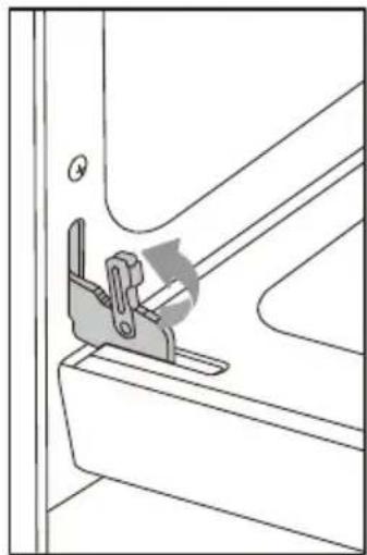
natural_image
Technical line drawing of a mechanical clamp or bracket assembly (no text or symbols)Drawer Removal and Reinstallation
During installation, service, and leveling, it may be easier to perform the necessary work if the drawer is removed. This makes the appliance lighter and visibility of anti-tip bracket is improved.
Follow these instructions below to remove and reinstall the drawer.
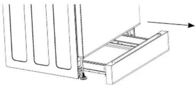
To remove drawer, fully extend drawer until it can't be pulled out and raise the drawer panel up, then pull out the drawer.
To reinstall the drawer, align the rails on the drawer with the slides on the range and push drawer in. Open and close drawer to ensure slide rails are operating properly.
Rail
The plastic bracket on drawer box
natural_image
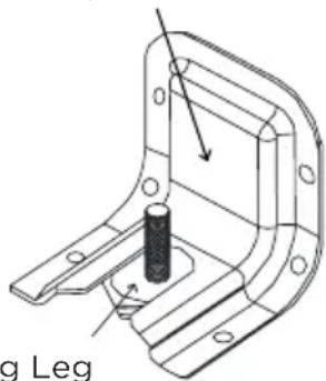
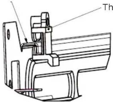
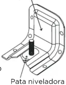
Technical line drawing of a mechanical assembly with a bracket and rod, showing no text or symbolsAnti-Tip Bracket Installation

WARNING
TIP OVER HAZARD
- A child or adult can tip the range and be killed. Verify the anti-tip device has been properly installed and engaged per installation instructions. Ensure the anti-tip device is re-engaged when the range is moved.
- Do not operate the range without the anti-tip device in place and engaged. Failure to do so can result in death or serious burns to children or adults. Do not remove the leveling legs. Doing so will prevent the range from being secured by the anti-tip device.
To reduce the risk of tipping of the range, the range must be secured to the floor by the properly installed anti-tip bracket and screws packed with the range. Failure to install the anti-tip bracket will allow the range to tip over if excessive weight is placed on an open door or if child climbs upon it. Serious injury might result from spilled hot liquids or from the range itself.

The anti-tip kit is provided with the range. If the anti-tip bracket is missing, damaged, or needs replaced, a replacement kit will be provided free-of-charge by contacting Midea customer service at 1-866-646-4332 or by visiting midea.com/us/support.
If range is ever moved to a different location, the anti-tip brackets must also be moved and installed with the range. If range is removed from service, secure door closed or remove door to minimize tip over risk. (See "Door Removal and Reinstallation" section in this manual or under "Cleaning and Maintenance" in the User's Manual for instructions on how to remove door.)
Directions:
- Using the template provided with anti-tip kit, locate the preferred location for installation of the anti-tip bracket and mark the location of the screw holes. Bracket may be installed at either the back-left or back-right corner of the installation space. Only one anti-tip bracket needs installed.
natural_image
Pure architectural line drawing of a structural beam or support structure without any text, numbers, or symbols- Attach anti-tip bracket to floor or wall.
- Wood Construction Installation: Drill a 1/8" pilot hole where screws are to be located. If bracket is to be mounted to the wall, drill pilot hole at an approximate 20° downward angle. Screw must enter wood.
- Masonry Construction Installation: Due to the variety of masonry materials that may be present at installation site, L hardware is not provided for attaching the anti-tip bracket to masonry. If bracket is to be mounted to masonry or ceramic floors, attach anti-tip bracket using two 5/16" OD sleeve anchors (with 1/4" bolt - either hex bolt head or hex nut head) rated for minimum 3001b tension for the masonry material present at installation site.
FANSTEN BRACKET
(FLOOR MOUNTING ONLY)
Electrical Supply Connection

WARNING
ELECTRICAL SHOCK HAZARD
- Installation must be electrically grounded in accordance with local codes or, in the absence of local codes, with the National Electrical Code, NFPA 70 or the Canadian Electric Code, CSA C22.1-O2.
- Do not use an extension cord with this product.
- The power supply cord and plug should not be modified. If it will not fit the outlet, have a proper outlet Installed by a qualified electrician.
- Remove the house fuse or open the circuit breaker before beginning installation.
- Effective January 1,1996, the National Electrical Code requires that new construction (not existing) utilize a 4-conductor connection to an electric range.
- Be sure your appliance is properly installed and grounded by a qualified service provider.
This appliance must be supplied with the proper voltage and frequency, and be connected to an individual, properly grounded branch circuit, protected by a circuit breaker or fuse having amperage as specified on the rating plate. The rating plate is located above the drawer on the oven frame. After installation, instruct the resident/owner where the main range electrical disconnect is located and how to operate it.
A 3-wire or 4-wire, split-phase 208/120 VAC or 240/120 VAC, 60 Hz electrical system must be used.
If the electrical service provided does not meet the above specifications, have a licensed electrician install an approved outlet.
Use only a 3-conductor or a 4-conductor UL-listed range cord rated 40A or 50A. These cords may be provided with crimped ring or fork terminals on the wire. A strain relief device must be used when attaching the cord to the range. Because range terminals are not accessible after the range is in position, a flexible service conduit or cord must be used. Allow 2-3 ft of slack in the line so that the range can be moved if servicing is ever necessary.
For Canadian installations, simply plug the attached power cord to the residential outlet. Outlet must be properly grounded and in accordance with the Canadian Electrical Code (CSA Standard C22.1 Part 1) and any local electrical code requirements.
natural_image
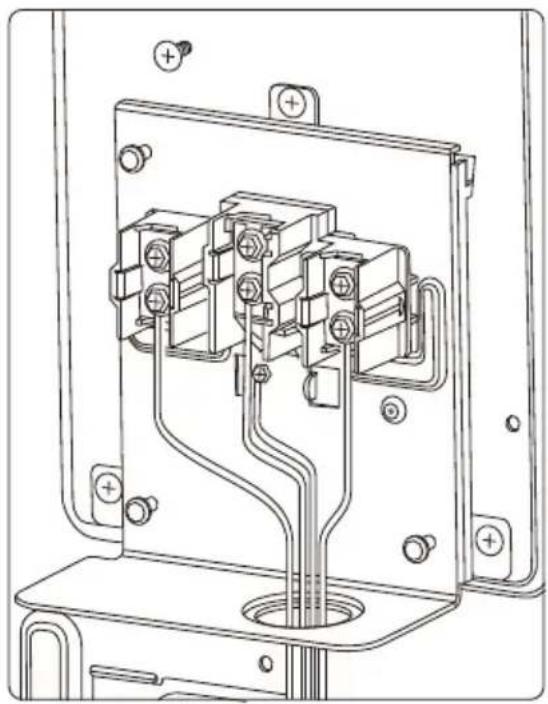
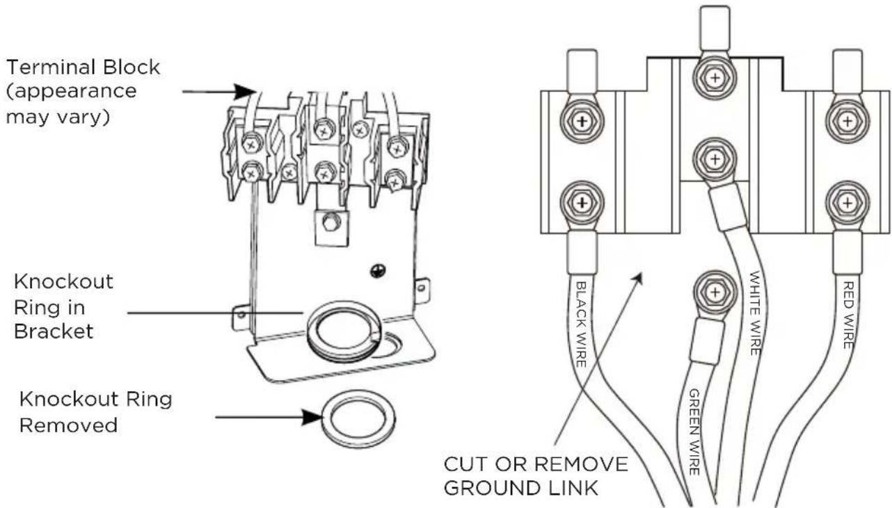
Technical line drawing of an electric plug and its corresponding socket (no text or symbols)Access the range electrical terminal block by removing the screw attaching the rear access cover on the back of the range.
4-Prong Power Cord Directions
- Thread the power cord and leads through the opening below the terminal block.
- Secure the cord by attaching the strain relief over the cord insulation jacket. (Strain relief must be placed on the "body" of the cord and not on the "leads.") Place the strain relief such that the leads have enough slack to connect to the terminal block without any stress or tension.
- Remove the 3 screws from the supply side of the terminal block.
- Remove the copper ground link connecting the neutral connection on the terminal block to the chassis ground.
- Attach the power cord leads to the terminal block and chassis as shown:
- Replace the access cover when complete.
natural_image
Technical line drawing of an electrical contactor or relay box with multiple terminals and wiring (no text or symbols)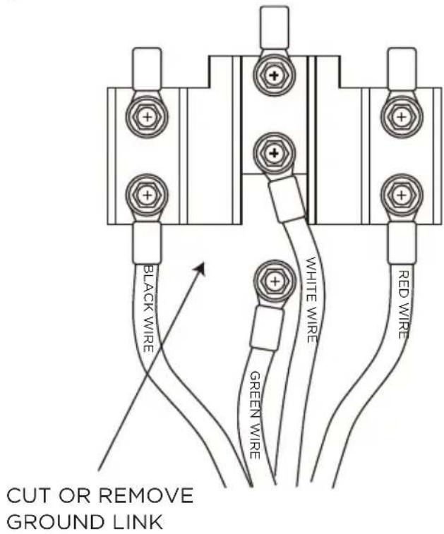
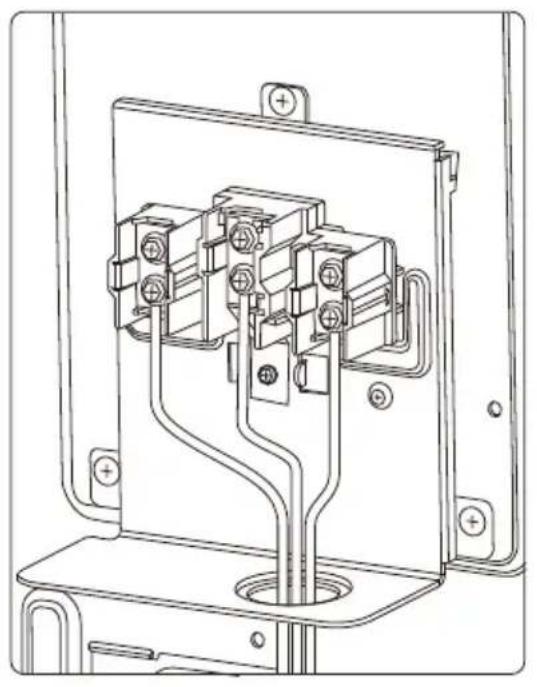
3-Prong Power Cord Directions
- Thread the power cord and leads through the opening below the terminal block.
- Secure the cord by attaching the strain relief over the cord insulation jacket. (Strain relief must be placed on the "body" of the cord and not on the "leads.") Place the strain relief such that the leads have enough slack to connect to the terminal block without any stress or tension.
- Remove the 3 screws from the supply side of the terminal block. Remove
- the copper ground link connecting the neutral connection on the terminal block to the chassis ground.
- Attach the power cord leads to the terminal block and chassis as shown:
- Replace the access cover when complete.
natural_image
Technical line drawing of an electrical contactor or connector assembly (no text or symbols visible)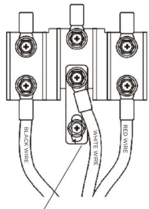
GROUND SCREW
Conduit Directions
- Knock out ring in the bracket to change the hole dimension.
- Insert the conduit strain relief into the opening below the terminal block.
- Tighten nut to hold conduit strain relief in place.
- Thread the conduit leads through the opening and strain relief.
- Tighten screws on strain relief to secure conduit in place. Place the conduit within the strain relief such that the leads have enough slack to connect to the terminal block without any stress or tension.
- Remove the 3 screws from the supply side of the terminal block. Attach the conduit leads to the terminal block and chassis as shown: Replace the access cover when complete.
EN-20
Placement and Leveling
CAUTION
LACERATION, FOREIGN OBJECT, CRUSH HAZARD
- When installing, moving, or servicing any appliance, wear proper protective equipment, including cut resistant gloves, steel-toed shoes, and safety glasses.
IMPORTANT
TO PREVENT DAMAGE
- Do not move unit by pushing or pulling on the door or control panel.
- Do not lift by the cooktop edges. Push, pull, or lift only on the body or structural areas, such as oven, oven face, or back corners of range. Move range by lifting, not sliding, to prevent damage to floors.
- Use cardboard, plywood, or stiff plastic to protect floors if sliding is necessary.
Getting the unit properly placed in the installation space and level may require multiple attempts.
It is recommended to measure and adjust leveling legs carefully before placing into the installation space, as the leveling legs may be difficult to adjust once the range is in its final position.
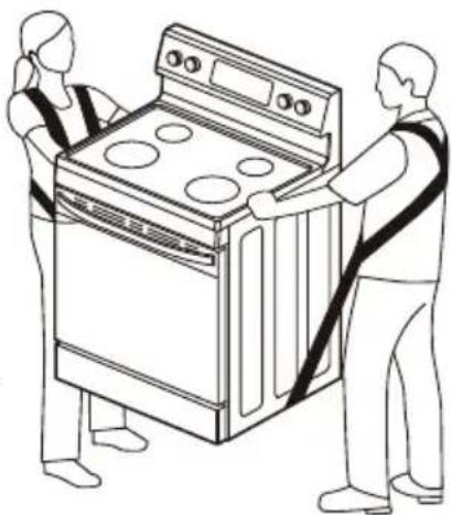
All ranges are heavy - sliding the range can damage the floor. Use care when moving the range. Use a belt when moving the range to prevent damaging the floor, or use cardboard, plywood, or stiff plastic to avoid damaging the floor while sliding the range.
natural_image
Line drawing of two people assembling a large oven (no text or symbols)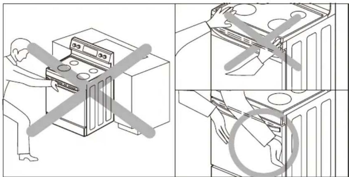
CAUTION
Please DO NOT push the unit strongly when you install. These actions can cause damage to the unit.
Please DO NOT grasp the cooktop and push when you install. (Grasp the L/R door area to push the unit)
Directions:
- Use tape measure to measure from the floor to the top of the counter top at all four corners of the installation space.
- While range is still positioned outside the installation space, adjust the leveling leg at each corner so that the distance from the floor to the underside of the cooktop edge matches the dimensions measured in the installation space.
- Using two people, move range into its final installation location, being careful not to damage countertops, floor, or appliance.
- IMPORTANT: Do not move unit by pushing or pulling on the door or control panel. Push, pull, or lift only on the body or structural areas, such as oven, oven face, or back corners of range.
- Be careful not to pinch or kink the gas or electrical connections. If unit does not move in smoothly, check for obstructions. Do not attempt to force the unit into position.
- Check that the gas supply line is not damaged.
-
Check to make sure the back leg of the range has engaged properly into the anti-tip bracket. If visual inspection is not possible:
-
Slide range forward
- Confirm anti-tip bracket is securely attached to floor or wall in correct position according to installation instructions.
- Fully slide the range back against the wall so that leveling leg engages with anti-tip bracket.
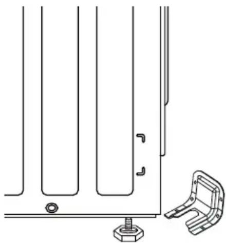
- To ensure baked goods, such as breads and cakes, come out even and level, confirm that the range is level by placing on the center rack position. Check level both front-to-back and side-to-side. Use adjustable pliers to adjust leveling legs as necessary to level the range.
- Reinstall door, drawer, and oven racks.
natural_image
Technical line drawing of a mechanical bracket assembly with mounting base and mounting bracket (no text or symbols)Cooktop Operation
Check the operation of all cooktop heating elements after the range has been completely installed, assembled, and electrical connections have been completed.
Directions:
For each burner, one at a time, rotate the knob to the "HI" position, confirm that the element begins to glow and heat up.
Confirm that the hot surface indicator light illuminates correctly.
Oven Operation
Check the operation of oven bake and broil elements after the range has been completely installed, assembled, and electrical connections have been completed.
Directions:
- Ensure door is closed, all packaging is removed, and oven is empty except for oven rack(s).
- Press the BAKE button on the oven control - the control will default to 350°F.
- Adjust temperature setting to 170^ .
-
Press the START/ENTER button on the oven control.
-
Listen for relays on the electronic control to "click."
- Without touching the oven bottom, after a couple minutes, confirm that heat can be felt radiating from the oven bottom.
- Allow BAKE mode until unit has preheated to 170°F. Confirm that display shows "PRE" and that preheat signals when temperature is reached.
- Press the CLEAR/OFF button to stop the bake mode.
- Press the BROIL button on the oven control.
- Press the START/ENTER button on the oven control.
- Without touching the broil element, after a couple minutes, confirm that heat can be felt radiating from the broil element. After several minutes, the broil element can be visually seen to start glowing red.
- Press the CLEAR/OFF button to stop the broil mode.
- If anything does not operate correctly, have the operation investigated by qualified service provider
Final Installation Checklist:
The installation process is complete. As a final check to confirm all steps have been completed successfully, the installer must read through the following checklist and initial each item indicating the work was performed according to these instructions:
- Installation space has been confirmed to meet the Clearances and Dimensions requirements, including that airflow is unobstructed at the front of the unit.
- Anti-tip bracket has been properly installed, and the range leveling leg has been confirmed to engage correctly with anti-tip bracket.
- Electrical supply has been properly connected to the range, in accordance with all applicable codes and regulations.
- Conversion for LP gas and high-altitude installations has been completed, if necessary.
- Oven operation and oven controls have been verified to work correctly.
- The oven door and drawer have been installed properly and operate correctly. Oven door closes completely.
- All instructions, including this manual, conversion instructions, and anti-tip bracket instructions, have been left with the owner/resident, with directions to retain for future reference.
TROUBLESHOOTING
Read before calling for service
Midea is committed to providing you with a quality appliance that works as expected. If you find something that is not working as anticipated, check the table below for helpful hints and advice that might save you the time and expense of calling for repair.
Cooktop
| Problem Possible Reason | |
| Unable to maintain a rolling boil or will not cook fast enough. | Improper cookware - Only use pans with flat bottoms and that match the diameter of the cooktop heating element selected.Large pots and pans can lose a lot of heat from the top -cover pan with a lid to retain heat better. |
| Cooktop will not operate. | If control panel display is not lit, appliance may not be receiving power - check circuit breaker or fuse has not tripped and that cord is properly plugged in. |
| Cooktop heating element does not glow steadily. | This is normal - cooktop heating element will cycle off/on to maintain the power level selected at the knob. This is normal even on the highest setting. |
| Cooktop heating element does not glow when power level is reduced. | This is normal - cooktop heating element will begin cycling again once the heating element has cooled slightly. |
| Cooktop glass is scratched. | Incorrect cleaning method used - scratches cannot be removed, but further scratching can be avoided by following the cleaning instructions in this manual.Cookware with rough bottom has been used or cookware has been slid across cooktop - scratches cannot be removed, but further scratching can be avoided by ensuring cookware is flat-bottomed, smooth, clean, and not slid across cooktop. |
Cooktop
| Problem Possible Reason | |
| Cooktop is discolored. • Cooktop is not cleaned thoroughly- see section in this manual on care and cleaning of cooktop. | |
| Cooktop is pitted. | • Sugary spill has occurred on hot glass - this cannot be repaired. Service must be called to replace the cooktop glass. |
Oven
| Problem Possible Reason | |
| Strong "burning" or "oily" odor when using new oven. | ·This is normal with a new range and will disappear after a few uses. Still, to be careful, you should double-check that all packaging has been removed from the appliance - check around door sides and inside drawer. |
| Control is dark and will not respond | ·If control panel display shows only ""] or ""] [", the control is in Sabbath Mode. Refer to that section for how to operate control and how to exit Sabbath Mode. |
| Control is lit but will not respond | ·Check that "CONTROL LOCK" has not been activated. |
| Food is not baking evenly - top gets done faster/slower than bottom. | ·Make sure you are using the recommended rack settings. See "Rack Positions" at the start of the "Oven Operation" section.·Recipe may perform better at different rack position. Moving food down one rack position will cause the bottom to become darker and top to become lighter. Moving food up one rack position will cause bottom to become lighter and top to become darker. |
| Oven light is not working | ·Oven light may be burned out. Follow instructions in "Cleaning and Maintenance" of user" manual. |
Oven
| Problem Possible Reason | |
| Smoke or steam is coming from the openings at the back of the cooktop. | It is normal for steam to be released from the oven vent at the back of the cooktop. If the exhaust has no smell (orsmells like normal baking food), do not be alarmed.If the exhaust smells like burning food, check that the food is not burning and that there is no spillage or splattering in the oven that may be producing the smoke.If the exhaust smells like any thing else is burning (plastic, wood, etc.), turn oven off and make sure smoking stops. Contact a qualified service provider for repairs. |
| "E" and a number appears in display | This is a error code. Press "CLEAR/OFF" to clear the display and stop beeping. If necessary, reset power to the oven by cycling circuit breaker off and on. If error code remains or repeats, write down error code and contact a qualified service provider for repairs. |
2 YEAR LIMITED WARRANTY
This warranty is provided to the original purchaser at retail (the “Purchaser” or “you”) by Midea America Corp. (“Midea” or “we”), which warrants all parts of this Product, as described below. Midea warrants this Product to the Purchaser for personal, family or household use. This warranty covers performance and quality issues in materials and workmanship that appear under normal use and maintenance appearing within two years from the date of purchase. This warranty gives you specific rights, and you may also have other rights that vary from state to state.
WARRANTY LIMITATIONS
This warranty is given only to the original purchaser at retail in either the United States or Canada and may not be transferred to any subsequent buyer. This warranty does not apply to purchasers of our products for use or resale in a business; a separate commercial warranty may protect those purchasers.
This warranty does not cover any Product failure caused by:
a. Abuse, damage or use of the Product in violation of the Product instructions.
b. Modification to any Product or part.
c. Failure to maintain the Product or part as described in accordance with the Product instructions.
d. Faulty installation or application.
e. Use of parts or accessories not compatible with this Product.
f. Floods, fires, winds, lightning, accidents, corrosive atmosphere, or other conditions beyond Midea's control.
g. Interruption in electrical service or inadequate electrical service.
h. Replacement of fuses and replacement or resetting of circuit breakers.
i. Frozen or broken water pipes, water damage, moisture intrusion, mold or other biological growth.
j. The use, combination or linking of the Product to other products, processes or materials not provided by Midea.
WARRANTY REMEDY
If any quality or performance issue covered by this warranty is discovered during the warranty period, we will, at our option, repair or replace any such Product. This warranty is limited to Product repair or replacement by an authorized Midea servicer or dealer and does not cover any shipping cost, labor cost, customs duties, inland logistics cost, or cost of service, including any diagnostics, removal, transportation, or reinstallation costs. If we ask, you must return the Product to us.
WARRANTY DISCLAIMER; EXCLUSION OF DAMAGES
This is the only express warranty to consumers that we offer on our Products. ANY IMPLIED WARRANTIES BY MIDEA, INCLUDING BUT NOT LIMITED TO WARRANTIES OF MERCHANTABILITY AND FITNESS FOR PARTICULAR PURPOSE, ARE LIMITED TO THE DURATION OF THIS EXPRESS WARRANTY. Some states and provinces do not allow the exclusion of express warranties and/or limitations on how long an implied warranty lasts, so the above exclusion and/or limitation may not apply to you.
THE REMEDY DESCRIBED ABOVE IS THE ONLY ONE THAT WE WILL PROVIDE, EITHER UNDER THIS WARRANTY OR UNDER ANY WARRANTY ARISING BY OPERATION OF LAW. WE WILL NOT BE RESPONSIBLE FOR ANY CONSEQUENTIAL OR INCIDENTAL DAMAGES ARISING FROM THE BREACH OF THIS WARRANTY OR ANY OTHER WARRANTY, WHETHER EXPRESS OR IMPLIED, NEGLIGENCE OR OTHER TORT, OR ON
ANY STRICT LIABILITY THEORY, INCLUDING BUT NOT LIMITED TO LOST PROFITS.
Some states do not allow the exclusion or limitation of incidental or consequential damages, so the above exclusion may not apply to you.
WARRANTY CLAIMS PROCESS
For more information or to make a warranty claim, please visit:
https://www.midea.com/us/support
Or contact us at:
Telephone: 1-866-646-4332
Email: customerserviceusa@midea.com
You must have Your bill of sale, delivery slip, or appropriate proof of purchase to submit a warranty claim. The date of purchase establishes the warranty period, should service be required.
DISPUTE RESOLUTION
ARBITRATION CLAUSE. IMPORTANT. PLEASE REVIEW THIS ARBITRATION CLAUSE. IT AFFECTS YOUR LEGAL RIGHTS.
a. Parties: This arbitration clause (this “Arbitration Clause”) affects your rights against Midea and any of its affiliates or employees or agents, successors, or assigns, all of whom together are referred to below as “we” or “us” for ease of reference.
b. ARBITRATION REQUIREMENT: EXCEPT AS STATED BELOW, ANY DISPUTE BETWEEN YOU AND ANY OF US SHALL BE DECIDED BY NEUTRAL, BINDING ARBITRATION RATHER THAN IN COURT OR BY JURY TRIAL. “Dispute” will be given the broadest possible meaning allowable by law. It includes any dispute, claim, or controversy arising from or relating to your purchase of this Product, any warranty upon the Product, or the Product’s condition. It also includes determination of the scope or applicability of this Arbitration Clause. The arbitration requirement applies to claims in contract and tort, pursuant to statute, or otherwise.
C. CLASS-ARBITRATION WAIVER: ARBITRATION IS HANDLED ON AN INDIVIDUAL BASIS. IF A DISPUTE IS ARBITRATED, YOU AND WE EXPRESSLY WAIVE ANY RIGHT TO PARTICIPATE AS A CLASS REPRESENTATIVE OR CLASS MEMBER ON ANY CLASS CLAIM YOU MAY HAVE AGAINST US OR WE AGAINST YOU, OR AS A PRIVATE ATTORNEY GENERAL OR IN ANY OTHER REPRESENTATIVE CAPACITY, TO THE MAXIMUM EXTENT PERMITTED BY LAW. YOU AND WE ALSO WAIVE ANY RIGHT TO CLASS ARBITRATION OR ANY CONSOLIDATION OF INDIVIDUAL ARBITRATIONS.
d. Discovery and Other Rights: Discovery and rights to appeal in arbitration are generally more limited than in a lawsuit. This applies to both you and us. Other rights that you or we would have in court may not be available in arbitration. Please read this Arbitration Clause and consult the rules of the arbitration organizations listed below for more information.
e. SMALL CLAIMS COURT OPTION: YOU MAY CHOOSE TO LITIGATE ANY DISPUTE BETWEEN YOU AND ANY OF US IN SMALL CLAIMS COURT, RATHER THAN IN ARBITRATION, IF THE DISPUTE MEETS ALL REQUIREMENTS TO BE HEARD IN SMALL CLAIMS COURT.
f. Governing Law: For residents of the United States, the procedures and effect of the arbitration will be governed by the Federal Arbitration Act (9 U.S.C. § 1 et seq.) rather than by state law concerning arbitration. For residents of Canada, the procedures and effect of the arbitration will be governed by the applicable arbitration law of the province in which you purchased your Product. The law governing your substantive warranty rights and other claims will be the law of the state or province in which you purchased your Product. Any court having jurisdiction may enter judgment on the arbitration award.
g. Rules of the Arbitration: If the amount in controversy is less than \$250,000, the
arbitration will be decided by a single arbitrator. If the amount in controversy is greater than or equal to \$250,000, the arbitration will be decided by a panel of three arbitrators. The arbitrator(s) will be chosen pursuant to the rules of the administering arbitration organization. United States residents may choose JAMS (1920 Main Street, Ste. 300, Irvine, CA 92614, www.jamsadr.com), or, subject to our approval, any other arbitration organization. In addition, Canadian residents may choose the ADR Institute of Canada (234 Eglinton Ave. East, Suite 405, Toronto, Ontario, M4P 1K5, www.amic.org). These organizations' rules can be obtained by contacting the organization or visiting its website. If the chosen arbitration organization's rules conflict with this Arbitration Clause, the provisions of this Arbitration Clause control. The award of the arbitrator(s) shall be final and binding on all parties.
h. Location of the Arbitration Hearing: Unless applicable law provides otherwise, the arbitration hearing for United States residents will be conducted in the federal judicial district in which you reside (in your hometown area) or, for Canadian residents, in the province in which you reside, and, if you choose, will be in-person.
i. Costs of the Arbitration: Each party is responsible for its own attorney, expert, and other costs and fees unless applicable law requires otherwise. Notwithstanding the preceding sentence, and unless applicable law requires otherwise, if you are a consumer under the JAMS rules or the rules of another agreed upon arbitration administrator, Midea will pay or reimburse you for all reasonable fees or costs to the extent required by law or the applicable arbitration administrator's rules. Whether or not required by law or such rules, if you prevail at arbitration on any claim against Midea, Midea will reimburse you for any reasonable fees paid to the arbitration administrator in connection with the arbitration proceedings. Under no circumstances will Midea seek from you payment or reimbursement of any reasonable fees that Midea incurs in connection with the arbitration. If you are required to advance any fees or costs to JAMS or other agreed upon arbitration administrator, but you ask Midea to do so in your stead, Midea will consider and respond to your request.
j. Survival and Enforceability of this Arbitration Clause: This Arbitration Clause shall survive the expiration or termination, or any transfer, of the warranty on your Product. If any part of this Arbitration Clause, except waivers of class-action rights, is found to be unenforceable for any reason, the remainder of this clause and the warranty shall remain enforceable. If, in a case in which class-action allegations have been made, the waiver of class-action rights under this warranty is found to be unenforceable with respect to any part of the dispute, the parts of the dispute as to which the waiver of class-action rights have been found unenforceable will be severed and will proceed in court without reference or application of this Arbitration Clause. Any remaining parts will proceed in arbitration.
QUEBEC RESIDENTS
The arbitration provisions of this warranty shall not apply to residents of Quebec.
TRADEMARKS, COPYRIGHTS AND LEGAL STATEMENT
Midea logo, word marks, trade name, trade dress and all versions thereof are valuable assets of Midea Group and/or its affiliates (“Midea”), to which Midea owns trademarks, copyrights and other intellectual property rights, and all goodwill derived from using any part of an Midea trademark. Use of Midea trademark for commercial purposes without the prior written consent of Midea may constitute trademark infringement or unfair competition in violation of relevant laws.
This manual is created by Midea and Midea reserves all copyrights thereof. No entity or individual may use, duplicate, modify, distribute in whole or in part this manual, or bundle or sell with other products without the prior written consent of Midea.
All the described functions and instructions were up to date at the time of printing this manual. However, the actual product may vary due to improved functions and designs.
DATA PROTECTION NOTICE
For the provision of the services agreed with the customer, we agree to comply without restriction with all stipulations of applicable data protection law, in line with agreed countries within which services to the customer will be delivered.
Generally, our data processing is to fulfil our obligation under contract with you and for product safety reasons, to safeguard your rights in connection with warranty and product registration questions. In some cases, but only if appropriate data protection is ensured, personal data might be transferred to recipients located outside of the European Economic Area.
Further information are provided on request. You can contact our Data Protection Officer via MideaDPO@midea.com. To exercise your rights such as right to object your personal date being processed for direct marketing purposes, please contact us via MideaDPO@midea.com. To find further information, please follow the QR Code.

make yourself at home


natural_image
Line drawing of a standard open-plan electric stove with four circular vented opicoes (no text or symbols)COCINA ELÉCTRICA
natural_image
Line drawing of a cord with multiple wires and an electrical plug, no text or symbols presentnatural_image
Line drawing of a multi-pin electrical plug and its terminal socket (no text or symbols)natural_image
Technical line drawing of two bolted fasteners with hexagonal nuts and mounting holes (no text or symbols)natural_image
Line drawing of four common footwear and safety gear items: gloves, shoes, and goggles (no text or symbols)natural_image
Illustration of two stacks of folded paper sheets (no text or symbols)natural_image
Simple line drawing of a pencil resting on a rectangular surface (no text or symbols)natural_image
Line drawing of a drill bit and a cylindrical tool (no text or symbols)natural_image
Line drawing of a pair of pliers (no text or symbols)natural_image
Diagram of a door hinge mechanism with a scroll wheel and rotation arrow (no text or symbols)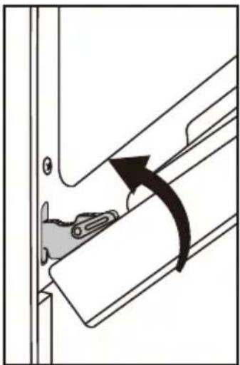
natural_image
Diagram of a door handle mechanism with an arrow indicating clockwise motion (no text or symbols present)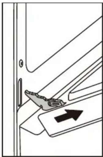
natural_image
Diagram of a door handle mechanism with an arrow indicating direction (no text or symbols present)natural_image
Technical line drawing of a mechanical bracket or bracket assembly with an arrow indicating a specific part (no text or symbols present)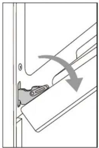
natural_image
Diagram of a door handle mechanism with an arrow indicating direction (no text or symbols present)
natural_image
Technical line drawing of a mechanical clamp or bracket assembly (no text or symbols)natural_image
Technical line drawing of a mechanical assembly with a bracket and vertical supports, showing no text or symbols.ES-16
ADVERTENCIA PELIGRO DE VUELCO
natural_image
Pure architectural line drawing of a structural beam or support structure without any text, numbers, or symbols
natural_image
Technical line drawing of a plug and its corresponding socket (no text or symbols)natural_image
Technical line drawing of an electrical enclosure with multiple circuit breakers and mounting brackets (no text or symbols)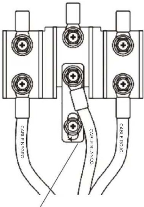
TORNILLO DE TOMA A TIERRA
natural_image
Line drawing of two people assembling a large oven (no text or symbols)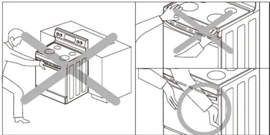

PRECAUCIÓN
natural_image
Technical line drawing of a mechanical assembly with mounting base and bracket (no text or symbols)https://www.midea.com/us/support
make yourself at home

natural_image
Line drawing of a standard open-plan electric stove with four circular vented opicoes (no text or symbols)GAMME ÉLECTRIQUE
INSTRUCTIONS D'INSTALLATION
MER30S2AST/MER30S2AWW/MER30S2ABB
INSTALLATION DU PRODUIT ----FR-09
DÉPANNAGE ----FR-26
GARANTIE LIMITÉE DE 2 ANS----FR-29
MARQUES, DROITS D'AUTEUR ET DÉCLARATION LÉGALE ----FR-32
AVIS SUR LA PROTECTION DES DONNÉES ----FR-33
CONSIGNES DE SÉCURITÉ IMPORTANTES
Utilisation prévue
AVERTISSEMENT RISQUES LIÉS AU FOUR
natural_image
Line drawing of a cord with multiple wires and an electrical plug, no text or symbols presentnatural_image
Line drawing of an electric shock absorber with a terminal plug and socket (no text or symbols)14-50P GETWIREDUSA FX359
natural_image
Technical line drawing of two bolted fasteners with hexagonal end caps (no text or symbols)natural_image
Line drawings of four common footwear and accessories: gloves, shoes, and goggles (no text or symbols)natural_image
Two hand-drawn sketch of folded paper sheets (no text or symbols)natural_image
Simple line drawing of a pencil and ruler on a rectangular base (no text or symbols)natural_image
Line drawing of a handheld electric drill with a cylindrical tool beside it (no text or symbols)INSTALLATION DU PRODUIT
LACÉRATION, CORPS ÉTRANGER, RISQUE D'ÉCRASEMENT
ZONE D'ALIMENTATION ÉLECTRIQUE
natural_image
Diagram of a door hinge mechanism with rotation arrow indicating clockwise motion (no text or symbols)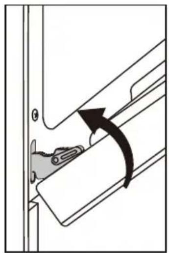
natural_image
Diagram of a door handle mechanism with an arrow indicating clockwise motion (no text or symbols)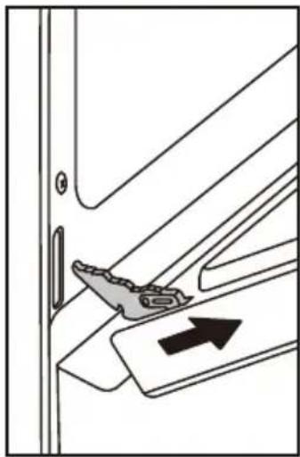
natural_image
Diagram of a door handle mechanism with an arrow indicating direction (no text or symbols present)natural_image
Technical line drawing of a mechanical bracket or bracket assembly with a gray arrow indicating a specific part (no text or symbols present)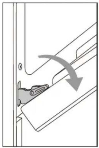
natural_image
Diagram showing a mechanical component with an arrow indicating direction, no text or symbols present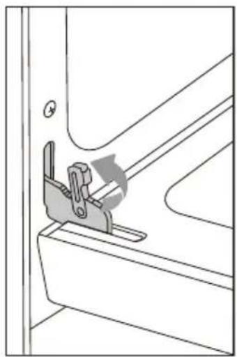
natural_image
Technical line drawing of a mechanical clamp or bracket assembly (no text or symbols)natural_image
Technical line drawing of a mechanical bracket with a cylindrical component inserted (no text or symbols)natural_image
Pure architectural line drawing of a staircase with horizontal beams and windows (no text or symbols)natural_image
Technical line drawing of an electric plug and its corresponding socket (no text or symbols)natural_image
Technical line drawing of an electrical contactor or connector assembly (no text or symbols visible)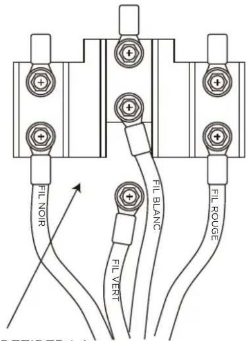
COUPER OU RETIRER LA LIAISON DE TERRE
natural_image
Technical line drawing of an electrical enclosure with multiple terminals and wiring (no text or symbols)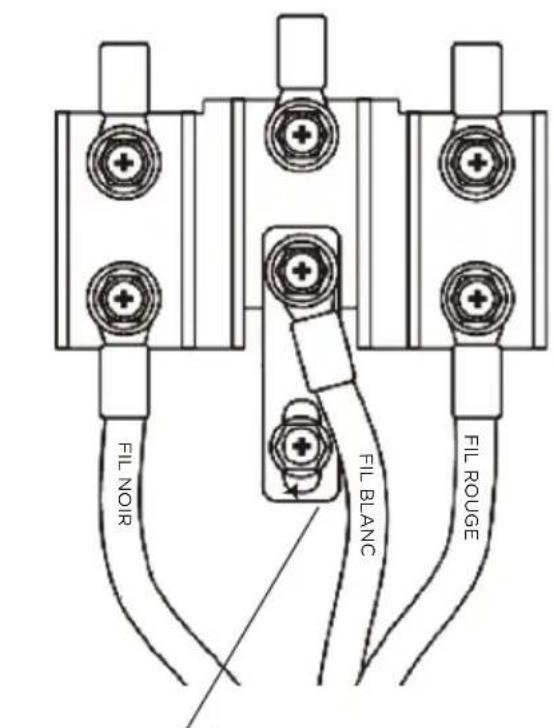
VIS DE MISE À LA TERRE
LACÉRATION, CORPS ÉTRANGER, RISQUE D'ÉCRASEMENT
natural_image
Line drawing of two people assembling a large oven (no text or symbols)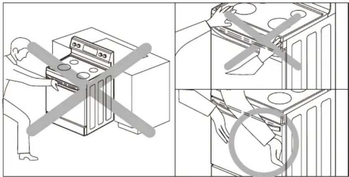
FR-22

MISE EN GARDE
natural_image
Technical line drawing of a mechanical assembly with mounting base and bracket (no text or symbols)https://www.midea.com/us/support
make yourself at home
