
GTC 12V-450-13 Professional - Measuring equipment BOSCH - Free user manual and instructions
Find the device manual for free GTC 12V-450-13 Professional BOSCH in PDF.
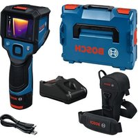

 FR
FR
 BG
BG
 CS
CS
 DA
DA
 DE
DE
 EL
EL
 EN
EN
 ES
ES
 ET
ET
 FI
FI
 HU
HU
 IT
IT
 KA
KA
 KK
KK
 LT
LT
 LV
LV
 MK
MK
 NL
NL
 NO
NO
 PL
PL
 PT
PT
 RO
RO
 RU
RU
 SK
SK
 SL
SL
 SV
SV
 TR
TR
 UK
UK
| Product type | Professional thermal camera |
| Dimensions (L x W x H) | 150 x 80 x 60 mm |
| Weight | 0.5 kg (without battery) |
| Power supply | Lithium-ion battery 12 V (Bosch Professional 12V series) |
| Temperature measurement range | -20 °C to 450 °C |
| Thermal resolution | 160 x 120 pixels |
| Measurement accuracy | ±2 °C or ±2 % of reading |
| Measurement distance (D:S) | 50:1 |
| Frame rate | 9 Hz |
| Field of view | 13° x 9° |
| Display | 2.8-inch TFT color display |
| Memory | Internal, capacity approx. 200 images |
| Data transfer | USB-C |
| Main functions | Spot measurement, isotherm, temperature alarm, automatic hot/cold spot |
| Maintenance and cleaning | Clean the lens with a soft, dry cloth; store in a dust-proof case |
| Safety | Do not point the laser at eyes; avoid shocks and humidity |
| Spare parts and repairability | Interchangeable battery; calibration recommended every 2 years |
| General information | Protection rating IP54; operating temperature -10 °C to 50 °C |
Frequently Asked Questions - GTC 12V-450-13 Professional BOSCH
User questions about GTC 12V-450-13 Professional BOSCH
0 question about this device. Answer the ones you know or ask your own.
Ask a new question about this device
Download the instructions for your Measuring equipment in PDF format for free! Find your manual GTC 12V-450-13 Professional - BOSCH and take your electronic device back in hand. On this page are published all the documents necessary for the use of your device. GTC 12V-450-13 Professional by BOSCH.
USER MANUAL GTC 12V-450-13 Professional BOSCH
No Original airfreinstruments
- Alkunosbiret phiont
English ...... Page 17
(1) (2) (3) (4) (5)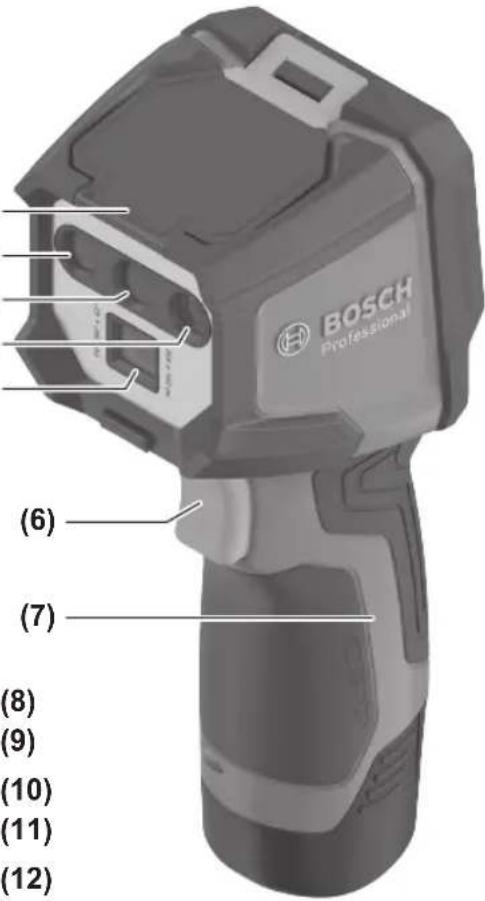
5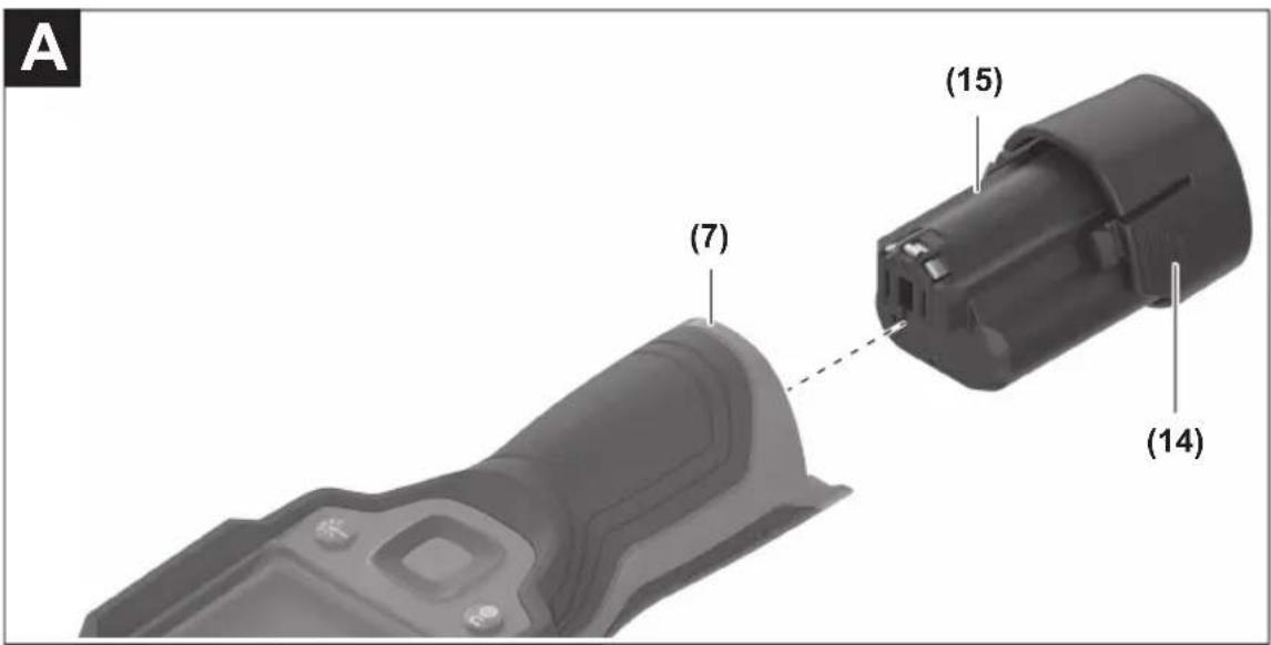
Deutsch
Sicherheitshinweise

www.bosch-pt.com/serviceaddresses
Transport
All instructions must be read and observed in order for the measuring tool to function safely. The safeguards integrated into the measuring tool may be compromised if the measuring tool is not used in accordance with these instructions. Never make warning signs on the measuring tool unrecognisable. SAVE THESE INSTRUCTIONS FOR FUTURE REFERENCE AND INCLUDE THEM WITH THE MEASURING TOOL WHEN TRANSFERRING IT TO A THIRD PARTY.
▶ Warning! If operating or adjustment devices other than those specified here are used or other procedures are carried out, this can lead to dangerous exposure to radiation. The measuring tool is delivered with a laser warning sign (marked in the illustration of the measuring tool on the graphics page). If the text of the laser warning label is not in your national language, stick the provided warning label in your national language over it before operating for the first time.
Do not direct the laser beam at persons or animals and do not stare into the direct or reflected laser beam yourself. You could blind somebody, cause accidents or damage your eyes.
▶ If laser radiation hits your eye, you must close your eyes and immediately turn your head away from the beam. ▶ Do not make any modifications to the laser equipment. ▶ Do not use the laser goggles (accessory) as protective goggles. The laser goggles make the laser beam easier to see; they do not protect you against laser radiation. ▶ Do not use the laser goggles (accessory) as sunglasses or while driving. The laser goggles do not provide full UV protection and impair your ability to see colours. ▶ Have the measuring tool repaired only by a qualified specialist using only original replacement parts. This will ensure that the safety of the measuring tool is maintained. ▶ Do not let children use the laser measuring tool unsupervised. They could unintentionally blind themselves or other persons. ▶ Do not use the measuring tool in explosive atmospheres which contain flammable liquids, gases or dust. Sparks may be produced inside the measuring tool, which can ignite dust or fumes. ▶ Do not modify or open the battery. There is a risk of short-circuiting.
18 | English
In case of damage and improper use of the battery, vapours may be emitted. The battery can set alight or explode. Ensure the area is well ventilated and seek medical attention should you experience any adverse effects. The vapours may irritate the respiratory system. If used incorrectly or if the battery is damaged, flammable liquid may be ejected from the battery. Contact with this liquid should be avoided. If contact accidentally occurs, rinse off with water. If the liquid comes into contact with your eyes, seek additional medical attention. Liquid ejected from the battery may cause irritation or burns. The battery can be damaged by pointed objects such as nails or screwdrivers or by force applied externally. An internal short circuit may occur, causing the battery to burn, smoke, explode or overheat. When the battery is not in use, keep it away from paper clips, coins, keys, nails, screws or other small metal objects that could make a connection from one terminal to another. A short circuit between the battery terminals may cause burns or a fire. ▶ Only use the battery with products from the manufacturer. This is the only way in which you can protect the battery against dangerous overload. ▶ Only charge the batteries using chargers recommended by the manufacturer. A charger that is suitable for one type of battery may pose a fire risk when used with a different battery.

Protect the battery against heat, e.g. against continuous intense sunlight, fire, dirt, water and moisture. There is a risk of explosion and short-circuiting.
WARNING

Ensure that the coin cell is kept out of the reach of children. Coin cells are dangerous.
▶ Coin cells must never be swallowed or inserted into any other part of the body. If you suspect that someone has swallowed a coin cell or that a coin cell has entered the body in another way, seek medical attention immediately. Swallowing coin cells can result in severe internal burns and death within 2 hours. ▶ Ensure that coin cell replacement is carried out properly. There is a risk of explosion. ▶ Only use the coin cells listed in this operating manual. Do not use any other coin cells or other forms of electrical power supply. ▶ Do not attempt to recharge the coin cell and do not short circuit the coin cell. The coin cell may leak, explode, catch fire and cause personal injury. ▶ Remove and dispose of drained coin cell correctly. Drained coin cell may leak and damage the product or cause personal injury.
▶ Do not overheat the coin cell or throw it into fire. The coin cell may leak, explode, catch fire and cause personal injury. ▶ Do not damage the coin cell and take the coin cell apart. The coin cell may leak, explode, catch fire and cause personal injury. ▶ Do not allow damaged coin cells to come into contact with water. Leaking lithium may mix with water to create hydrogen, which could cause a fire, an explosion, or personal injury. ▶ If you cannot close the coin cell holder correctly and fully, stop using the measuring tool, remove the coin cell and have the measuring tool repaired. ▶ High temperature differences in a thermal image may cause even high temperatures to be shown in a colour associated with low temperatures. Coming into contact with such an area may cause burns. ▶ Temperature measurements will only be correct if the emissivity setting matches the emissivity of the object. Otherwise, object temperatures could be shown to be hotter or colder than they are, which may present a danger if touched. ▶ Do not point the measuring tool directly at the sun or at high-performance CO2 lasers. This may damage the detector. ▶ Protect the measuring tool, particularly the area around the camera and infrared lens, from moisture, snow, dust and dirt. The reception lens could fog up or become contaminated and distort the measurements. Incorrect settings on the tool and other atmospheric influences may make the measurements inaccurate. Object temperatures could be shown to be hotter or colder than they are, which may present a danger if touched.
Product Description and Specifications
Please observe the illustrations at the beginning of this operating manual.
Intended Use
This thermal imaging camera is designed for the contactless measurement of surface temperatures.
The displayed thermal image shows the temperature distribution in the thermal imaging camera's field of view and therefore enables temperature deviations to be depicted in different colours.
When used correctly, this makes it possible to examine areas and objects in a contactless manner for temperature differences and discrepancies in order to make components and/or any weaknesses visible, including:
– Thermal insulation and other types of insulation (e.g. locating thermal bridges) - Active heating and hot water pipes (e.g. underfloor heating) in floors and walls
- Overheated electrical components (e.g. fuses or terminals)
- Faulty or damaged machine parts (e.g. overheating due to faulty ball bearings)
The measuring tool is not suitable for measuring the temperature of gases.
The measuring tool must not be used for human medical purposes.
Please find out about veterinary application at www.bosch-professional.com/thermal.
The measuring tool is suitable for indoor and outdoor use.
This product is a consumer laser product in accordance with EN 50689.
The light of this measuring tool is intended to illuminate the direct work area of the measuring tool in order to take pictures and is not intended as a continuous work light.
The laser point must not be used as a laser pointer. It is solely for marking out the area being measured.
Product Features
The numbering of the product features shown refers to the illustration of the measuring tool on the graphic page.
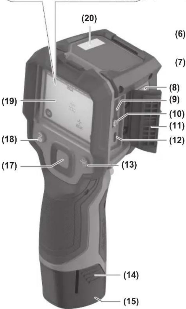
(1) Protective cap (2) Laser beam outlet aperture (3) Visual camera (4) Worklight (5) Infrared sensor (6) Pause/start measurement button (7) Battery bay (8) Laser warning label (9) Coin cell holder (10) Coin cell holder screw (11) Flap for USB port and coin cell holder (12) USB Type-C® port a) (13) Laser button
(14) Rechargeable battery/battery adapter release button (15) Rechargeable battery b) (16) USB Type-C® cable b) (17) Multi-function button (18) On/off button/Back button (19) Display (20) Serial number (21) Battery adapter cover (22) Batteries b) (23) Battery adapter cap a) USB Type-C® and USB-C® are trademarks of USB Implementers Forum. b) The accessories illustrated or described are not included as standard delivery.
Display Elements
(a) Emissivity indicator (b) Reflected temperature indicator (c) Average temperature indicator (d) Memory full symbol (e) Worklight symbol (f) Laser symbol (g) Battery charge indicator (h) Maximum surface temperature in the measuring range indicator (i) Scale (j) Minimum surface temperature in the measuring range indicator (k) Fix temperature scale symbol (l) Cold spot indicator (example) (m) Crosshairs with temperature indicator (n) Hotspot indicator (example) (o) Menu symbol
Technical Data
| Thermal imaging camera GTC 12V-450-13 | |
| Article number | 3 601 K83 900 |
| Resolution of infrared sensor 256 × 192 px | |
| Thermal sensitivityA) | ≤ 50 mK |
| Spectral range 8–14 μm | |
| Field of view (FOV)A) | 55.6° × 42° |
| Spatial resolution (IFOV) 3.79 mrad | |
| Focus distanceA) | ≥ 0.5 m |
| Focus Fixed | |
| Thermal image refresh rate ≤ 9 Hz | |
| Surface temperature measuring rangeA) | -20 °C to +450 °C |
20 | English
Thermal imaging camera GTC 12V-450-13
| Surface temperature measuring accuracy A)B(C) | |
| >0 °C to ≤ +100 °C D) | ±2 °C |
| > +100 °C E) | ±2 % |
| Temperature resolution 0.1 °C | |
| Display type TFT | |
| Display size 2.8" | |
| Display resolution 480 × 360 px | |
| Integrated visual camera resolution 2 MP (640 × 480 px) | |
| Image format .jpg | |
| Elements saved per saving process 1 × thermal image (screenshot) | |
| 1 × real visual image incl. temperature values (metadata) | |
| Max. number of images in internal image memory 500 | |
| Max. altitude 2000 m | |
| Pollution degree according to IEC 61010-1 2 | F) |
| Max. relative humidity A) | 90 % |
| Laser class 2 | |
| Laser type < 1 mW, 645–660 nm | |
| Divergence of the laser beam 1.5 mrad (full angle) | |
| Power supply | |
| - Rechargeable battery pack (Li-ion) 12 V | |
| - Non-rechargeable batteries (alkaline manganese, with bat-tery adapter) | 4 × 1.5 V LR6 (AA) |
| - Rechargeable batteries (NiMH, with battery adapter) | 4 × 1.2 V HR6 (AA) |
| Operating time G) | |
| - Rechargeable battery pack (Li-ion) HII | 8 h |
| - Non-rechargeable batteries (alkaline manganese) | 4 h |
| System time power supply | CR1225 (3 V lithium battery) |
| USB standard | 2.0 |
| USB Port | USB Type-C |
| Weight J) | 0.354 kg |
| Dimensions (length × width × height) K) | 89 × 79 × 209 mm |
| Protection rating (excluding [rechargeable] batteries, in the vertical position) | IP54 |
| Recommended ambient temperature during charging | 0 °C to +35 °C |
| Permitted ambient temperatures | |
| - During operation | -10 °C to +50 °C |
| - During storage with a rechargeable battery | -20 °C to +50 °C |
| - During storage without a rechargeable battery | -20 °C to +70 °C |
| Recommended rechargeable batteries GBA 12V... |
Thermal imaging camera GTC 12V-450-13
Recommended battery chargers GAL 12...
GAX 18...
A) In accordance with standard VDI 5585 (average)
B) At an ambient temperature of 20–23 °C and an emissivity of ≥ 0.95, measuring distance: 1 m, operating time: > 5 min, aperture of 150 mm, with the worklight and laser switched off
C) Plus use-dependent deviation (e.g. reflection, distance, ambient temperature)
D) Applies to the centre point, all other pixels additionally ±1 °C
E) Applies to the centre point, all other pixels additionally ±1%
F) Only non-conductive deposits occur, whereby occasional temporary conductivity caused by condensation is expected.
G) With the worklight switched off and medium display brightness
H) Depending on battery in use
I) At an ambient temperature of 20-30 °C
J) Weight without rechargeable batteries/battery adapter/non-rechargeable batteries
K) with GBA 12V 2.0Ah or battery adapter
The serial number (20) on the type plate is used to clearly identify your measuring tool.
Measuring Tool Power Supply
The measuring tool can be operated either with a Bosch lithium-ion battery, with commercially available non-rechargeable batteries or with commercially available NiMH rechargeable batteries.
Operation with Rechargeable Battery (see figure A)
▶ Use only the chargers listed in the technical data. Only these chargers are matched to the lithium-ion battery of your measuring tool.
Note: Lithium-ion rechargeable batteries are supplied partially charged according to international transport regulations. To ensure full rechargeable battery capacity, fully charge the rechargeable battery before using your tool for the first time.
To insert the charged battery pack (15), slide it into the battery bay (7) until you feel it engage.
To remove the battery pack (15), press the release buttons (14) and pull the battery pack out of the battery bay (7). Do not use force to do this.
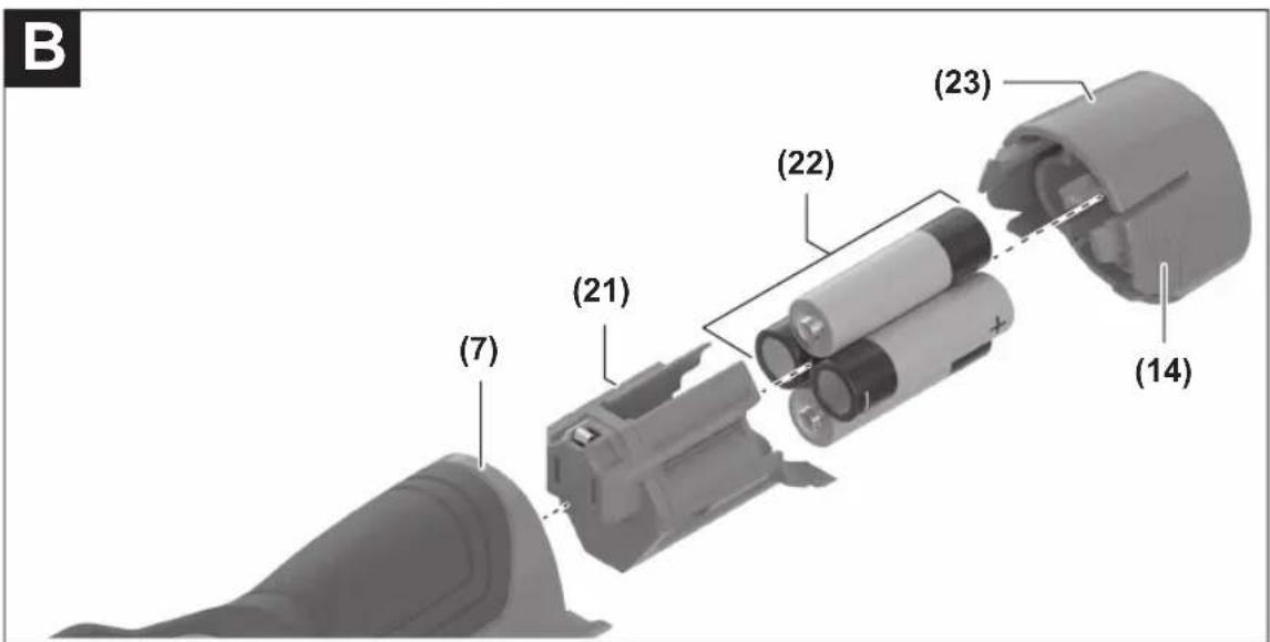
Operation with non-rechargeable batteries (see figure B)
Using alkali-manganese non-rechargeable batteries or NiMH rechargeable batteries is recommended for operation of the measuring tool.
The batteries are inserted into the battery adapter.
The battery adapter is intended only for use in designated Bosch measuring tools and must not be used with power tools.
To insert the batteries, slide the cover (21) of the battery adapter into the battery bay (7). Place the batteries into the cover as per the illustration on the cap (23). Slide the cap over the receptacle until you feel it click into place.
To remove the batteries (22), press the release buttons (14) on the cap (23) and pull the cap off. Remove the batteries. To remove the cover (21) from inside the battery bay, reach into the cover and pull it out of the measuring tool, applying light pressure to the side wall as you do so.
Always replace all the batteries at the same time. Only use batteries from the same manufacturer and which have the same capacity.
Take the batteries out of the measuring tool when you are not using it for a prolonged period of time. The batteries can corrode during prolonged storage in the measuring tool.
Recommendations for Optimal Handling of the Battery
Protect the battery against moisture and water.
Only store the battery within a temperature range of -20 to 50 °C. Do not leave the battery in your car in the summer, for example.
A significantly reduced operating time after charging indicates that the battery has deteriorated and must be replaced. Follow the instructions on correct disposal.
Operation
Protect the measuring tool from moisture and direct sunlight.
Do not expose the measuring tool to any extreme temperatures or variations in temperature. For example, do not leave it in a car for extended periods of time. In case of large variations in temperature, allow the measuring tool to adjust to the ambient temperature before putting it into operation. The precision of the measuring tool may be compromised if exposed to extreme temperatures or variations in temperature.
Make sure that the measuring tool is correctly acclimatised. In case of large variations in temperature, acclimatisation can take up to 60 minutes. This may be the case, for example, if you store the measuring tool in a cool car and then perform a measurement in a warm building.
Avoid hard knocks to the measuring tool or dropping it. After severe external influences and in the event of ab-
normalities in the functionality, you should have the measuring tool checked by an authorised Bosch after-sales service agent.
Starting Operation
Switching On For the First Time
You need to adjust a few basic settings when you switch on the measuring tool for the first time or after resetting it to factory settings. Select the required values by pressing the top, bottom, left or right of the multi-function button (17). Press the centre of the multi-function button (17) to confirm your selection. Once you have confirmed the selection, the next setting will show on the display. The total number and the number of remaining settings is displayed in the status-bar at the top.
The following basic settings are available:
Switching On and Off
To take a measurement, fold the protective cap (1) upwards. Make sure that the infrared sensor is not closed off or covered while working.
To switch on the measuring tool, press the on/off button (18). A start sequence will appear on the display (19). The measuring tool begins to take measurements as soon as the start sequence has finished and does so continuously until it is switched off.
Note: In the first few minutes, the measuring tool may self-calibrate several times, as the sensor temperature and ambient temperature have not yet been brought into line. Performing sensor calibration again enables precise measurement.
During this time, the temperature indicator may show \~. If the ambient temperature fluctuates significantly, this effect is increased. If possible, you should therefore turn on the measuring tool a few minutes before starting to measure, so that the tool can stabilise thermally.
To switch off the measuring tool, press the on/off button (18) for longer than 1 s. The measuring tool saves all settings and then switches itself off. Close the protective cap (1) to transport the measuring tool safely.
In the main menu, you can choose whether and after how long the measuring tool automatically switches off (see "Main Menu", page 24).
If the battery pack or the measuring tool is not within the operating temperature range specified in the technical data, the measuring tool will switch off automatically after a brief warning (see "Errors – Causes and Corrective Measures", page 26). Allow the measuring tool to reach the correct temperature and then switch it back on.
Navigating in the Various Menus
Navigate in the various menus of the measuring tool:
- Open the menu bar: Press the centre or left of the multifunction button (17) to confirm your selection. The menu bars at the right and left appear on the display, the main menu is highlighted.
- Browse in the left menu bar/navigate the main menu: Press the top, bottom, left or right of the multi-function button (17).
- Switch to the left or right menu bar: Press the left or right of the multi-function button (17).
- Confirm selection/switch to the submenu: Press the centre of the multi-function button (17).
- To switch from a submenu back to a higher-level menu: Press the back button (18).
Measurement Preparations
Setting the emissivity for surface temperature measurements
The emissivity of an object depends on the material and the structure of its surface. This specifies how much infrared thermal radiation the object emits compared with an ideal radiant warmer (black body, emissivity = 1 ) and accordingly has a value between 0 and 1.
To determine the surface temperature, the tool performs a contactless measurement of the natural infrared thermal radiation emitted by the object at which the tool is aimed. To ensure correct measurement, the emissivity setting on the measuring tool must be checked before every measurement and adapted to the measuring object if necessary. The preset emissivities in the measuring tool are reference values.
You can select one of the preset emissivities or enter an exact numerical value. Set the required emissivity via the
→ menu (see "Main Menu", page 24).
▶ Temperature measurements will only be correct if the emissivity setting and the emissivity of the object match.
The lower the emissivity, the greater the effect of the reflected temperature on the measuring result. Always adjust the reflected temperature when changing the emissivity. Set the reflected temperature via the
parameters> → menu (see "Main Menu", page 24).
Temperature differences allegedly shown by the measuring tool may be caused by different temperatures and/or different emissivity levels. If the emissivity levels are very different, the depicted temperature differences may differ considerably from the actual temperature differences.
If there are multiple objects made of different materials or that have different structures in the measuring range, the displayed temperature values are only accurate for the objects that match the emissivity setting. For all other objects (with different emissivity levels), the displayed colour differences can be used as an indication of temperature relationships.
ences can be used as an indication of temperature relationships.
Highly reflective or shiny surfaces (e.g. shiny tiles or polished metals) may significantly distort or impair the results shown. If necessary, mask the measuring surface with a dark, matt adhesive tape that conducts heat well. Allow the tape to briefly reach the correct temperature on the surface. Make sure that a favourable measuring angle is used on reflective surfaces in order to ensure that the thermal radiation reflected by other objects does not distort the result. For example, the reflection of your own emitted body heat may interfere with the measurement when measuring head-on from a perpendicular position. On a level surface, the outline and temperature of your body could therefore be displayed (reflected value), and these values do not correspond to the actual temperature of the measured surface (emitted value or real value of the surface).
Highly reflective or shiny surfaces (e.g., shiny tiles or polished metals) may significantly distort or impair the results shown. If necessary, mask the measuring surface with a dark, matt adhesive tape that conducts heat well. Allow the tape to briefly reach the correct temperature on the surface. Make sure that a favorable measuring angle is used on reflective surfaces in order to ensure that the thermal radiation reflected by other objects does not distort the result. For example, the reflection of your own emitted body heat may interfere with the measurement when measuring head-on from a perpendicular position. On a level surface, the outline and temperature of your body could therefore be displayed (reflected value), and these values do not correspond to the actual temperature of the measured surface (emitted value or real value of the surface).
Measuring through transparent materials (e.g., glass or transparent plastics) is fundamentally not possible.
Consequently, the more suitable and stable the measuring conditions are, the more accurate and reliable the measurement readings are. Not only do significant fluctuations in the temperature of the environmental conditions have an impact, the accuracy can also be impaired by significant fluctuations in the temperatures of the object being measured. Infrared temperature measurement is impaired by smoke, steam/high humidity or dusty air.
Information for achieving improved measurement accuracy:
- Move as close as possible to the object to be measured to minimize interfering factors between you and the surface to be measured.
- Ventilate indoor areas prior to measurement, especially when the air is contaminated or extremely steamy. Once ventilated, allow the room to reacclimatise until it returns to the usual temperature.
Marking the Measuring Point
▶ Do not direct the laser beam at persons or animals and do not stare into the laser beam yourself (even from a distance).
The measuring tool is equipped with a laser for marking the measuring point.
Press and hold down the laser button (13). The laser symbol (f) is displayed in the statusbar and a red circle appears around the crosshairs (m). The superimposition of the laser and crosshairs corresponds exactly at a distance of 1 m. If you release the laser button (13), the laser switches off.
Assigning Temperatures on the Basis of the Scale
A scale (i) is shown on the right-hand side of the display. The values at the top and bottom end are oriented to the maximum (h) and minimum (j) temperature recorded in the thermal image. For the scale, 99.99 % of the total pixels are evaluated. Colours are assigned to temperature values with a uniform distribution in the image (linearly).
Different shades can therefore be used to assign temperatures within these two limit values. For example, a temperature that is exactly between the maximum and minimum value is assigned to the centre colour range of the scale.
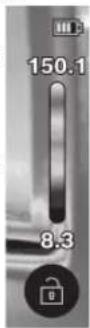
To determine the temperature of a specific area, move the measuring tool so that the crosshairs with temperature display (m) are aimed at the required point or area. In the automatic setting, the colour spectrum of the scale is always distributed linearly (= uniformly) across the entire measuring range between the maximum and minimum temperatures.
The measuring tool displays all measured temperatures in the measuring range in relation to one another. If heat is displayed as blue in the colour palette in an area, for example in a colour representation, this means that the blue areas are among the colder measured values in the current measuring range. However, these areas may still be in a temperature range which could cause injuries in certain circumstances. You should therefore always note the temperatures displayed on the scale or at the crosshairs themselves.
Functions
Observe the information on navigating the various menus (see "Navigating in the Various Menus", page 22)

Illuminating the Object Being Measured
The measuring tool is equipped with a worklight (4). It is intended to illuminate the direct work area of the measuring tool in order to take pictures and is not intended as a continuous work light.
To switch on/off the worklight, open the left side bar. Scroll to the / menu item and confirm your selection. When the worklight is switched on, this is indicated in the statusbar.
The light is automatically switched off after 2 minutes to avoid affecting the measuring accuracy.
You can change the automatic switch-off time in the menu under .
24 | English
Superimposition of Thermal Image and Real Image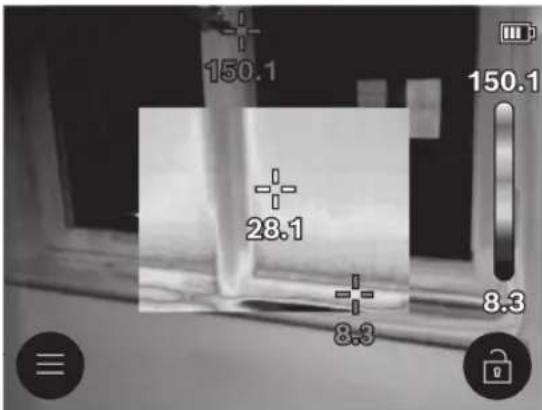
For improved orientation (= local assignment of the thermal image displayed), with matched temperature ranges, a real visual image can additionally be inserted.
Note: The superimposition of the real image and thermal image corresponds exactly at a distance of 1 m. If the tool is closer to or further away from the object being measured, this fundamentally results in misalignment of the real image and thermal image. This misalignment can be compensated for using special Bosch applications. Information about the applications and their compatibilities can be found on the product page of the measuring tool or at www.bosch-professional.com/thermal.
The measuring tool offers the following options:
Complete infrared image
Only the thermal image is displayed.

- Transparency
The thermal image displayed is placed on top of the real image in such a way that it is transparent. This enables improved detection of objects.
To activate/deactivate the setting, open the left side bar and scroll to the / menu item. Confirm your selection by pressing the centre of the multi-function button (17).
- Image in image
The thermal image displayed is cropped and the surrounding area is shown as a real image. This setting improves the local assignment of the measuring range.
To activate/deactivate the setting, open the left side bar and scroll to the / menu item. Confirm your selection by pressing the centre of the multi-function button (17).
Adjusting the Colour Display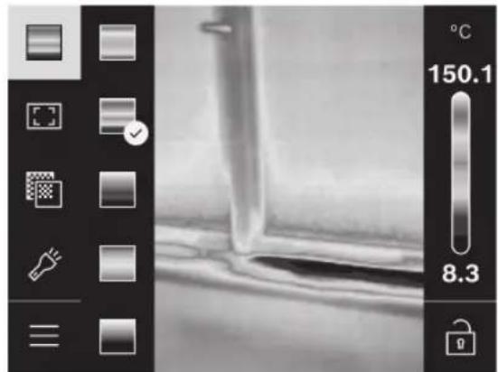
Depending on the measurement conditions, different colour palettes may make it easier to analyse the thermal image and display objects or circumstances more clearly in the display. This does not affect the measured temperatures. The only change is the way in which the temperature values are displayed.
To switch the colour palette, open the side bar and browse to the "Colour palette" menu item. Confirm your selection by pressing the centre of the multi-function button (17).
Fixing the Scale
The colour distribution in the thermal image is adjusted automatically but can be fixed by pressing the right of the multifunction button (17) followed by the centre. This enables a comparison to be made between thermal images taken under different temperature conditions (e.g. when checking several rooms for thermal bridges). It also allows an extremely cold or hot object to be hidden in the thermal image. This object would otherwise distort the image (e.g. a radiator as a hot object when searching for thermal bridges).
To switch the scale back to automatic, open the right side bar and press the centre of the multi-function button (17). The temperatures are now dynamic again and adapt to the measured minimum and maximum values.
Main Menu
Open the left side bar (see "Navigating in the Various Menus", page 22). Press the centre of the multi-function button (17) to access the main menu.
- Under this menu item you can delete the saved images individually or you can delete all images at once.
-
- (a)
A selection of saved emissivities is available for some of the most common materials. To make the search easier, the values are combined into groups in the emissivity catalogue. First select the relevant category and then choose the relevant material in the menu item. If you know the exact emissivity of the object you want to measure, you can also set
it as a numerical value in the menu item.
- (b):
Setting this parameter can improve the accuracy of the measuring result, especially with low-emissivity (= high-reflection) materials. In some situations (especially in indoor areas), the reflected temperature corresponds to the ambient temperature. If there are objects with greatly deviating temperatures close to highly reflective objects, this value should be adjusted as the measurement may be affected. Press the left or right of the multi-function button (17) to do so.
To ensure high accuracy across the entire measuring range, measurements are carried out in two temperature ranges. With the measuring function, the measuring tool automatically selects the appropriate temperature range according to the temperature distribution in the thermal image. When doing so, it assesses how many measured values fall above a certain temperature threshold. If very small but hot objects are being measured, it may select the low temperature range that is not suitable for high temperatures. This can be determined from the preceding symbol \~ on the temperature display. In such cases, switch to the <100 °C ... 450 °C> or <-20 °C ... 100 °C> measuring function, in which the colour distribution corresponds to the set temperature range. The setting is marked on the scale with an arrow pointing up or down.
The hottest point (= measuring pixel) is indicated by red crosshairs in the thermal image. This facilitates the search for critical areas (e.g. a loose contact terminal in the control cabinet).
The coldest point (= measuring pixel) is indicated by blue crosshairs in the thermal image. This facilitates the search for critical areas (e.g. a leak in a window).
The average temperature (c) is displayed at the top left of the thermal image (average temperature of all measured values in the thermal image). This can help you to determine the reflected temperature.
Under this menu item, you can change the brightness of the display lighting.
Under this menu item, you can select the time interval after which the worklight will automatically switch off if no buttons are pressed.
Under this menu item, you can select the time interval after which the measuring tool will automatically switch off if no buttons are pressed. You can also deactivate automatic switch-off by selecting the setting.
This submenu not only allows you to set the time and date but also to change their respective formats.
Under this menu item, you can select the language used in the display.
Under this menu item, you can reset the measuring tool to factory settings and permanently delete all data. This may take several minutes. Then press either right of the multi-function button (17) to delete all files or the left of the multi-function button (17) to cancel the process.
Under this menu item, you can access information about the measuring tool. There you will find the serial number of the measuring tool and the installed software version. This is also where you can find more detailed information about the measuring tool and about the software update.
You can also press the measuring button (6) to exit any menu and return to the home screen.
Updating the Measuring Tool Software
If required, you can update the software of the measuring tool via the USB Type-C® interface. To find out more about this, visit:
www.bosch-professional.com/thermal-update.
Documenting Measurements
Saving Measurements
The measuring tool begins to take measurements as soon as it is switched on and does so continuously until it is switched off.
To save an image, point the camera at the required measuring object and press the "Measurement" button (6). The image is saved in the measuring tool's internal memory. The measurement is frozen and shown in the display. This enables you to carefully view the image and to make retrospective adjustments (e.g. to the colour palette). If you do not wish to save the frozen image, restart measuring mode by pressing the "Measurement" button (6). If you wish to save the image in the measuring tool's internal memory, press the centre of the multi-function button (17).
Calling Up Saved Images
Proceed as follows to call up saved thermal images:
- Press the centre of the multi-function button (17) again immediately after saving. The preview of the most recently saved photo now appears in the display.
- Alternatively, you can access the saved photos in the menu item.
- Press the right or left of the multi-function button (17) to switch between the saved thermal images.
The visual image has been saved alongside the thermal image. Press the top or bottom of the multi-function button (17) to open this.
The measuring tool switches to full-screen view after 5 s. In the full-screen view, the title bar is hidden so that you can see all the details of the thermal image.
You can switch between views by pressing the top and bottom of the multi-function button (17).
Deleting saved images
Press the centre of the multi-function button (17) to delete individual thermal images or all thermal images at once. A submenu will open.
- Here you can select whether you want to delete only this image or all images. Confirm the selection by pressing the centre of the multi-function button (17).
When selecting, you can choose between , and . Confirm the selection by pressing the centre of the multi-function button (17).
In this submenu, you can also see the information on the emissivity and reflecting temperature.
Data fragments of the images remain stored in the memory and could be reconstructed. You can select <Tool
settings> → in the main menu to permanently delete.
Data Transfer
Data Transfer via USB Port
Open the flap (11) for the USB Type-C® port. Connect the USB Type-C® port (12) of the measuring tool to your computer via the USB Type-C® cable (16) provided.
Now switch on the measuring tool using the on/off button (18).
Open the file browser on your computer and select the GTC_450 drive. The saved files can be copied from the internal memory of the measuring tool, moved to your computer or deleted.
As soon as you have finished the required operation, disconnect the drive from the computer following the standard procedure and then use the on/off button (18) to switch the measuring tool off again.
Caution: Always disconnect the drive from your operating system first (eject drive), as failure to do so may damage the internal memory of the measuring tool.
Remove the USB Type-C® cable and close the (11) flap.
Always keep the flap of the USB port closed so that dust and splashes cannot enter the housing.
Note: Use USB to connect the measuring tool to a computer only. The measuring tool may be damaged if connected to other devices.
Note: The USB Type-C® interface can only be used for data transfer. It is not suitable for charging non-rechargeable and rechargeable batteries.
Post-Editing the Thermal Images
You can post-edit the saved thermal images using special Bosch applications. Information about the applications and their compatibilities can be found on the product page of the measuring tool or at www.bosch-professional.com/thermal.
Errors – Causes and Corrective Measures
In the event of a fault, the measuring tool will restart and can then continue to be used. If the fault persists, the following overview may help you.
Error Cause Corrective measure
| Measuring tool cannot be switched on. | Battery pack/batteries empty Charge the battery pack or change the batteries. | ||
 | Battery (pack) fault Change the batteries or the rechargeable battery pack. | ||
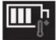 | Battery pack/batteries too hot or too cold | Allow the battery pack to reach the correct temperature or change the battery pack or batteries. | |
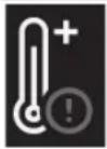 | Measuring tool too hot or too cold | Allow the measuring tool to reach the correct temperature. | |
Error Cause Corrective measure
USB port or USB cable defective
Check whether the measuring tool can be connected to a different computer. If it cannot, send the measuring tool to an authorised Bosch after-sales service centre.
Measuring tool cannot be connected to a computer.
Note: Always use the USB cable included in the scope of delivery.
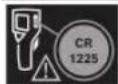
Coin cell empty Change the coin cell (see "Changing the Coin Cell
(see figure C)", page 27). Confirm the change with "OK" by pressing the centre of the multi-function button (17).
Glossary of terms
To find out more, visit: www.bosch-professional.com/thermal.
Infrared thermal radiation
Infrared thermal radiation is electromagnetic radiation emitted by every body above 0 Kelvin (-273 °C). The amount of radiation depends on the temperature and the emissivity of the body.
Emissivity
The emissivity of an object depends on the material and the structure of its surface. This specifies how much infrared thermal radiation the object emits compared with an ideal radiant warmer (black body, emissivity = 1 ) and accordingly has a value between 0 and 1.
Thermal bridge
A thermal bridge is defined as a position on the external wall of a building, where there is a localised increase in heat loss due to a structural defect.
Thermal bridges can lead to an increased risk of mould.
Reflected Temperature/Reflectivity of an Object
The reflected temperature is the thermal radiation that is not emitted by the object itself. Depending on the structure and material, background radiation is reflected in the object to be measured, therefore distorting the actual temperature result.
Distance from the Object
The distance between the object being measured and the measuring tool influences the captured area size per pixel. You can capture increasingly large objects as the distance from the object becomes greater.
| Distance (m) Size of infrared pixels (mm) | Infrared range width × height (m) |
| 0.30 1.14 ~ 0.29 × 0.22 | |
| 0.55 2.08 ~ 0.53 × 0.40 | |
| 1.00 3.79 ~ 0.97 × 0.73 | |
| 2.00 7.58 ~ 1.94 × 1.46 | |
| 5.00 18.95 ~ 4.85 × 3.64 |
Maintenance and Service
Maintenance and Cleaning
Only store and transport the measuring tool in a suitable container, such as the original packaging.
Keep the measuring tool clean at all times. A dirty infrared sensor (5) may impair the measuring accuracy.
When cleaning the measuring tool, ensure that no liquids enter the tool.
Do not attempt to remove dirt from the infrared sensor (5), camera (3), worklight (4) or laser outlet aperture (2) using sharp objects. Do not wipe over the infrared sensor and camera (risk of scratching).
The areas around the outlet aperture of the laser in particular should be cleaned on a regular basis. Make sure to check for lint when doing this.
Please contact an authorised Bosch after-sales service centre if you want to have your measuring tool recalibrated.
If repairs are required, send in the measuring tool in its original packaging.
There are no parts which can be serviced by the user on the measuring tool. Opening the housing shell can destroy the measuring tool.
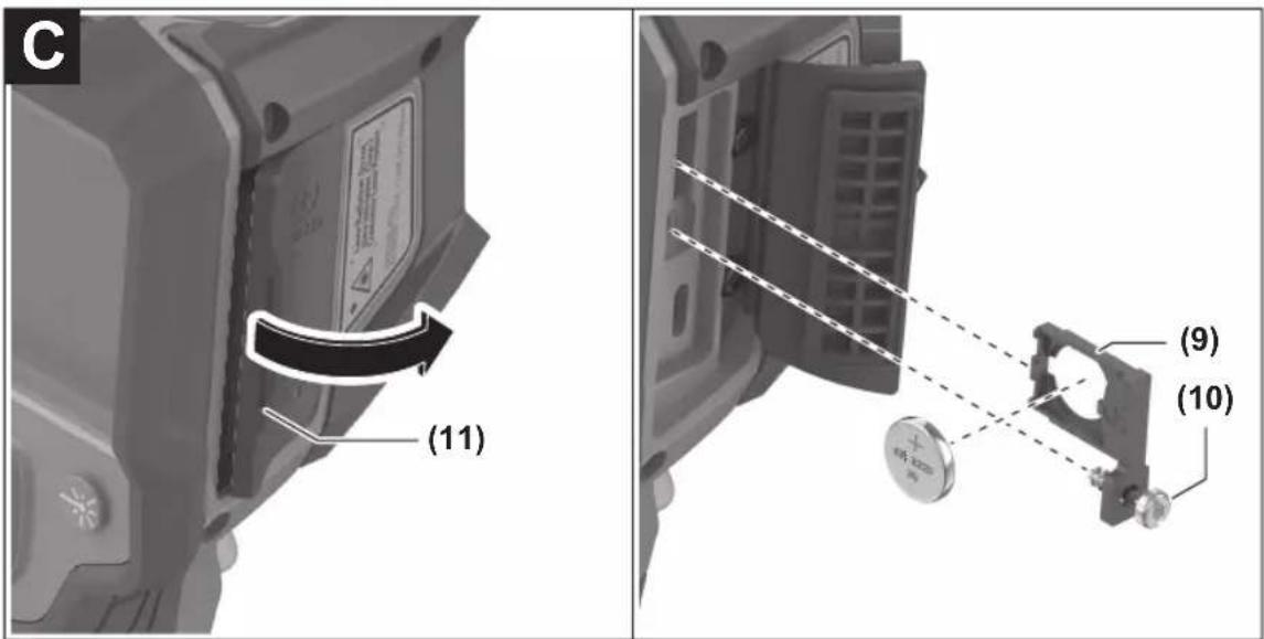
Changing the Coin Cell (see figure C)
Open the flap (11).
Unscrew the screw (10) on the coin cell holder. Pull the coin cell holder (9) out of the measuring tool. Change the coin cell. Retighten the screw (10) after inserting the coin cell holder.
After-Sales Service and Application Service
Our after-sales service responds to your questions concerning maintenance and repair of your product as well as spare parts. You can find explosion drawings and information on spare parts at: www.bosch-pt.com
The Bosch product use advice team will be happy to help you with any questions about our products and their accessories.
In all correspondence and spare parts orders, please always include the 10-digit article number given on the nameplate of the product.
Great Britain
Robert Bosch Ltd. (B.S.C.)
P.O. Box 98
Broadwater Park
North Orbital Road
Denham Uxbridge
UB 9 5HJ
At www.bosch-pt.co.uk you can order spare parts or arrange the collection of a product in need of servicing or repair.
Tel. Service: (0344) 7360109
E-Mail: boschservicecentre@bosch.com
You can find further service addresses at:
www.bosch-pt.com/serviceaddresses
Transport
The recommended lithium-ion batteries are subject to legislation on the transport of dangerous goods. The user can transport the batteries by road without further requirements.
When the batteries are shipped by third parties (e.g. air transport or forwarding agency), special requirements on packaging and labelling (e.g. ADR regulations) must be met. A dangerous goods expert must be consulted when preparing the items for shipping.
Dispatch battery packs only when the housing is undamaged. Tape or mask off open contacts and pack up the battery in such a manner that it cannot move around in the packaging. Please also observe the possibility of more detailed national regulations.
Disposal

Measuring tools, rechargeable/non-rechargeable batteries, accessories and packaging should be sorted for environmental-friendly recycling.
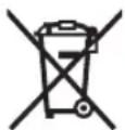
Do not dispose of the measuring tools or battery packs/batteries with household waste.
Only for EU countries:
Measuring tools that are no longer suitable for use and defective or used rechargeable batteries/batteries must be disposed of separately. Use the designated collection systems. If disposed incorrectly, waste electrical and electronic equipment may have harmful effects on the environment and human health, due to the potential presence of hazardous substances.
Only for United Kingdom:
According to The Waste Electrical and Electronic Equipment Regulations 2013 (SI 2013/3113) (as amended) and the Waste Batteries and Accumulators Regulations 2009 (SI 2009/890) (as amended), products that are no longer usable must be collected separately and disposed of in an environmentally friendly manner.
Battery packs/batteries:
Li-ion:
Please observe the notes in the section on transport (see
"Transport", page 28).
French
Safety Instructions

To use the measuring tool safely and securely, read all instructions carefully and follow them. Failure to comply with these instructions may impair the protective functions of the measuring tool. Ensure that the warning labels on the measuring tool remain legible at all times. KEEP THESE INSTRUCTIONS IN A SAFE PLACE AND HAND THEM OVER TO ANY NEW USER OF THE MEASURING TOOL.
▶ Caution – The use of other operating or adjusting devices than those specified here, or the execution of other procedures, may result in hazardous radiation exposure. The measuring tool is supplied with a laser warning label (marked in the illustration of the measuring tool on the graphics page). If the text on the laser warning label is not in your language, cover the label with the sticker in your language that is supplied before first use.
▶ Attention – L'utilisation d'autres dispositifs de commande ou d'ajustage que ceux indiqués ici ou l'exécution d'autres procédures risque de provoquer une exposition dangereuse aux rayonnements. L'appareil de mesure est fourni avec une étiquette d'avertissement laser (repérée dans la représentation de l'appareil de mesure sur la page des graphiques). Si le texte de l'étiquette d'avertissement laser n'est pas dans votre langue, recouvrez l'étiquette par l'autocollant dans votre langue qui est fourni, avant de procéder à la première mise en service.
Never point the laser beam at people or animals, and never look into the laser beam projected by the device or its reflection. You could dazzle people, cause accidents, or lead to eye injuries.
If the laser beam strikes an eye, close your eyes immediately and move your head away from the beam. Never make any modifications to the laser device. ▶ Do not modify the laser device. Do not use the laser viewing glasses (accessory not included) as protective glasses. Laser viewing glasses only help to see the laser beam better; they do not protect against the effects of laser radiation. Do not use the laser viewing glasses (accessory not included) as sunglasses or for road traffic. Laser viewing glasses do not provide complete UV protection and they distort color perception.
▶ Have the measuring tool serviced only by a qualified repair person using only original replacement parts. This will ensure that the safety of the measuring tool is maintained. ▶ Do not let children use the laser measuring tool without supervision. They could direct the beam into their own eyes or inadvertently dazzle other people. ▶ Do not operate the measuring tool in explosive atmospheres, in the presence of flammable liquids, gases, or dust. The measuring tool can produce sparks that may ignite dust or vapors. Do not modify the battery or open it. Risk of short circuit. If the battery is damaged or used improperly, vapors may escape. The battery can burn or explode. Ventilate the room and consult a doctor if you feel unwell. Vapors can cause respiratory irritation. In case of improper use or a defective battery, flammable liquid may leak from the battery. Avoid contact with this liquid. In case of accidental contact, rinse thoroughly with water. If the liquid gets into the eyes, also consult a doctor promptly. Liquid escaping from the battery can cause irritation or burns. Sharp objects such as a nail or screwdriver and applying external force to the housing can damage the battery. This can result in an internal short circuit and the battery may ignite, emit smoke, explode, or overheat. When the battery is not in use, keep it away from any metal objects (such as paper clips, coins, keys, nails, screws, or other small objects) that could create a short circuit between the contacts. Short-circuiting the battery contacts can cause burns or fire. Use the battery only with products from the manufacturer. This will exclude any risk of dangerous overload. ▶ Charge batteries only with chargers recommended by the manufacturer. A charger designed for a specific type of battery may cause a fire when used with other batteries.

Store the battery away from heat, protecting it from direct sunlight, fire, dirt, water, and moisture. There is a risk of explosion and short circuits.
WARNING


Make sure to never leave the button cell within the reach of children. Button cells are dangerous.
Button cells must never be ingested or inserted into body orifices. If ingestion of a button cell or insertion into another body orifice is suspected, consult a doctor immediately. Ingestion of a button cell can cause severe burns within just 2 hours and can even lead to death. When replacing a button cell, please observe the rules and precautions for use. Otherwise, there is a risk of explosion. ▶ Please use only the type of button cell indicated in these operating instructions. Do not use any other button cell or any other power source. Do not attempt to recharge the button cell or short-circuit it. The button cell may then leak, explode, burn, and injure people. Remove discharged button cells and dispose of them in accordance with applicable legislation. Discharged button cells may leak and damage the product or injure people. ▶ Do not overheat the button cell or throw it into a fire. The button cell may then leak, explode, burn, and injure people. Do not damage the button cell or attempt to open it. The button cell may then leak, explode, burn, and injure people. ▶ Do not bring a damaged button cell into contact with water. Escaping lithium can produce hydrogen when reacting with water. There is then a risk of fire, explosion, or personal injury. Do not use the measuring tool anymore when the button cell holder can no longer be closed properly and completely. Remove the button cell and have the measuring tool repaired. High temperature differences in a thermal image can cause high temperatures to be displayed in a color that normally corresponds to low temperatures. There is a risk of burns upon contact with such a surface. For measured temperatures to be correct, the set emissivity rate and the actual emissivity rate of the object must match. Otherwise, the displayed temperature of objects may be too high or too low, which can pose a danger upon contact with the objects. ▶ Do not point the measuring tool directly at the sun or a powerful CO₂ laser. The detector may be damaged.
Protect the measuring tool from moisture, snow, dust, and dirt, especially the camera and the infrared lens. The receiving lens may fog up or become dirty and falsify measurements. Measurements can also be falsified by incorrect settings of the tool and other weather-related factors. The displayed temperature of objects may then be too high or too low, which can pose a danger upon contact with the objects.
Description of services and product
Please take note of the illustrations in the front part of the operating instructions.
Intended use
This thermal camera is designed for non-contact measurement of surface temperatures.
The displayed thermal image shows the temperature distribution in the field of view of the thermal camera and represents temperature differences by color differences.
When used appropriately, the thermal camera allows non-contact examination of surfaces and objects and makes visible, by means of temperature differences, parts/components/building elements or anomalies or weak points, in particular:
- Thermal insulation (e.g., highlighting thermal bridges),
- Heating and hot water pipes (e.g., underfloor heating) in floors and walls,
- Overheating electrical components (e.g., fuses or terminals),
- Defective or damaged machine parts (e.g., defective ball bearings causing overheating). The measuring device is not designed for measuring gas temperature.
It is not permitted to use the measuring device in the field of human medicine.
For use in the field of veterinary medicine, please visit www.bosch-professional.com/thermal.
The measuring device is designed for indoor and outdoor use.
This product is a consumer laser device according to EN 50689.
The LED light of this measuring device is intended to illuminate the direct measurement area for taking photos. It must not be used as a permanent light source.
The laser point is not designed for use as a laser pointer. It is only used to delimit the measurement surface.
Component parts
The numbering of the device components refers to the representation of the measuring device on the graphic page.
(1) Protective cover (2) Laser beam outlet (3) Photo camera (4) Illumination LED (5) Infrared sensor (6) Pause/Start measurement button (7) Battery compartment (8) Laser warning label (9) Button cell holder
(10) Screw for button cell holder
(11) Cover for USB socket/button cell holder
(12) USB Type-C® socket a)
(13) Laser button
(14) Battery/adapter release button
(15) Battery b)
(16) USB Type-C® cable b)
(17) Multifunction button
(18) On/Off/Back button
(19) Display
(20) Serial number
(21) Battery adapter body
(22) Batteries b)
(23) Battery adapter cover
a) USB Type-C® and USB-C® are registered trademarks of the USB Implementers Forum.
b) Not all accessories described or illustrated are included in the original delivery.
Displays
(a) Emissivity rate display (b) Reflected temperature display (c) Average temperature display (d) Memory full symbol (e) Lighting LED symbol (f) Laser symbol (g) Charge status indicator (h) Maximum surface temperature display in the measuring area (i) Scale (j) Minimum surface temperature display in the measuring area (k) Temperature scale freeze symbol (I) Cold spot display (example) (m) Reticle with temperature display (n) Hot spot display (example) (o) Menu symbol
Technical specifications
| Caméra thermique GTC 12V-450-13 | |
| Référence | 3 601 K83 900 |
| Résolution du capteur infrarouge 256 × 192 px | |
| Sensibilité thermique A) | ≤ 50 mK |
| Bande spectrale 8–14 μm | |
| Champ de vision (FOV) A) | 55,6° × 42° |
| Résolution spatiale (IFOV) 3,79 mrad | |
| Distance de focalisation A) | ≥ 0,5 m |
| Mise au point fixe | |
| Fréquence de rafraîchissement de l'image thermique ≤ 9 Hz | |
| Plage de mesure de températures de surface A) | -20 ... +450 °C |
| Précision de mesure des températures de surface A)(B)(C) | |
| >0 °C ... ≤ +100 °CD) | ±2 °C |
| >+100 °CE) | ±2 % |
| Résolution de température 0,1 °C | |
| Type d'écran TFT | |
| Taille de l'écran 2,8" | |
| Résolution d'écran 480 × 360 px | |
| Résolution de la caméra photo intégrée 2 MP (640 × 480 px) | |
| Format d'image .jpg | |
| Éléments enregistrés à chaque mémorisation 1 image thermique (capture d'écran)1 image réelle avec valeurs de température (métadonnées) | |
| Nombre maximal d'images enregistrables dans la mémoire d'images interne | 500 |
| Altitude d'utilisation maxi 2 000 m | |
| Degré d'encrassement selon CEI 61010-1 2 | F) |
| Humidité relative de l'air maxi A) | 90 % |
| Classe laser 2 | |
| Type de laser | < 1 mW, 645–660 nm |
| Divergence du faisceau laser | 1,5 mrad (angle plein) |
| Alimentation électrique | |
| – Batterie (Lithium-Ion) | 12 V |
| – Piles alcalines au manganèse (avec adaptateur piles) | 4 × 1,5 V LR6 (AA) |
| – Piles rechargeables (NiMH, avec adaptateur piles) | 4 × 1,2 V HR6 (AA) |
| Autonomie G) | |
| – Batterie (Lithium-Ion) H(j) | 8 h |
| – Piles (alcalines au manganèse) | 4 h |
| Alimentation en énergie de l'horloge système | CR1225 (pile au lithium de 3 V) |
| Norme USB | 2.0 |
| Interface USB | USB Type-C ® |
| Poids j) | 0,354 kg |
| Dimensions (longueur × largeur × hauteur) K) | 89 × 79 × 209 mm |
| Indice de protection (excepté batterie/piles, en position verti-cale) | IP54 |
32 | English
Thermal camera GTC 12V-450-13 Recommended ambient temperatures for charging 0 °C ... +35 °C
| Températures ambiantes admissibles | |
| - pendant le fonctionnement -10°C ... +50°C | |
| - en cas de stockage avec batterie -20°C ... +50°C | |
| - en cas de stockage sans batterie -20°C ... +70°C | |
| Batteries recommandées GBA 12V... | |
| Chargeurs recommandés GAL 12... | GAX 18... |
A) According to VDI 5585 standard (average value)
B) For ambient temperature of 20–23 °C, emissivity rate ≥ 0.95, measuring distance of 1 m, usage duration: > 5 min, opening of 150 mm, with lighting LED off and without laser beam
C) Without the deviation related to the type of use (e.g., reflection, distance, ambient temperature)
D) Valid for the midpoint, for all other pixels ±1 °C additionally
E) Valid for the midpoint, for all other pixels ±1 % additionally
F) Designed only for non-conductive dirt/soiling but occasionally tolerates conductivity due to condensation phenomena.
G) With lighting LED off and average screen brightness
H) depending on the battery used
I) for an ambient temperature of 20-30°C
J) Weight without battery/battery adapter/batteries
K) With GBA 12V 2.0Ah battery or battery adapter
The serial number (20) on the rating plate allows precise identification of your measuring device.
Power supply for the measuring device
The measuring device is designed to operate with a Bosch Lithium-Ion rechargeable battery, disposable batteries, or commercially available NiMH rechargeable batteries.
Operation with battery (see figure A)
Only use the chargers specified in the Technical Specifications. These chargers are the only ones suitable for the Lithium-Ion battery of your measuring device.
Note: International shipping regulations require that Lithium-Ion batteries be delivered partially charged. To ensure full performance, charge them completely before first use.
To insert the charged battery (15), push it into the battery compartment (7) until it audibly clicks into place.
To remove the battery (15), press the release tabs (14) on the battery and pull the battery out of its compartment (7). Do not force it.
Operation with batteries (see figure B)
For correct operation of the measuring tool, we recommend using alkaline manganese batteries or rechargeable NiMH batteries.
The batteries must be inserted into the battery adapter.
The battery adapter is intended solely for use with Bosch measuring tools designed for
this purpose. It is not designed for use with power tools.
To insert the batteries, push the body (21) of the battery adapter into the battery compartment (7). Place the batteries into the body as shown on the illustration on the cover (23). Slide the cover over the body until it audibly clicks into place.
To remove the batteries (22), press the release tabs (14) of the cover (23) and pull off the cover. Remove the batteries. To extract the body (21) from the battery compartment, insert a finger inside the body and pull it out of the measuring tool while applying slight pressure to the side wall.
Always replace all batteries at the same time. Use only batteries of the same brand and with the same capacity.
Remove the batteries from the measuring tool if you know that the measuring tool will not be used for an extended period. During prolonged storage, the batteries may corrode in the measuring tool.
Indications for optimal battery use
Protect the battery from moisture and water.
Store the battery only within a temperature range of -20 to 50 °C. For example, do not leave the battery in a car during summer.
A noticeable decrease in battery runtime over successive charges indicates that the battery has reached the end of its life and must be replaced.
Follow the instructions regarding disposal.
Operation
Protect the measuring tool from moisture and do not expose it directly to sunlight. Do not expose the measuring tool to extreme temperatures or sudden temperature changes. For example, do not leave it in a car exposed to the sun for too long. After a sudden temperature change, wait until the measuring tool has reached ambient temperature before using it. Extreme temperatures or sudden temperature changes can reduce the accuracy of the measuring tool. Allow the measuring tool to reach ambient temperature before switching it on. In case of a significant temperature difference, this can take up to 60 minutes. Such a scenario can occur, for example, when moving the tool from a cold vehicle into a heated building. Avoid impacts or drops of the measuring tool. After exposing the measuring tool to extreme external conditions or if abnormal operation is detected, have it checked at an authorized Bosch service center.
Start-up
On first start-up
On first start-up of the measuring tool or after a reset to factory settings, certain basic settings need to be made. Select the desired values by pressing at the bottom, top, left, or right of the multi-function button (17). Press the center of the multi-function button (17) to confirm your selection. Once you have confirmed the selection, the next setting appears on the display. The status bar at the top shows the total number of settings and the number of settings remaining.
The following basic settings are available:
Switching on/off
To take a measurement, lift the protective cover (1).
When using the camera, ensure that the infrared sensor is not blocked or covered.
To switch on the measuring tool, press the On/Off button (18). A start-up sequence appears on the display (19). Once the start-up sequence is complete, the measuring tool immediately begins measuring and continues to measure until it is switched off.
Note: During the first few minutes, the measuring tool may recalibrate itself several times as long as there is still a difference between the sensor temperature and the ambient temperature. The recalibration of the sen-
sor improves measurement accuracy.
During this time, \~ appears on the temperature display. This effect is intensified in the event of strong fluctuations in the ambient temperature. To avoid any inconvenience, switch on the measuring tool a few minutes before starting the measurement so that it has time to stabilize thermally.
To switch off the measuring tool, press the On/Off button (18) for more than 1 s. The measuring tool saves all settings before switching off. For safe transport of the measuring tool, close the protective cover (1).
You can set in the main menu whether and after how long the measuring tool should switch off automatically (see "Main menu", Page 36).
If the battery/measuring tool are outside the operating temperature range specified in the technical data, the measuring tool switches off automatically after a brief warning (see "Faults - Causes and remedies", Page 37). Allow the measuring tool to return to ambient temperature and switch it on again.
Navigating the menus
Navigating the menus of the measuring tool:
- To call up the menu bars: press the center or the left side of the multifunction button (17). The left and right menu bars appear, with the main menu highlighted.
- To scroll through the left menu bar/navigate in the main menu: press the bottom, top, left, or right of the multifunction button (17).
- To switch between the left and right menu bars: press the left or right side of the multifunction button (17).
- To confirm a selection/return to the main menu: press the center of the multifunction button (17).
- To return to the higher menu level from a submenu: press the Back button (18).
Preparing the measuring tool
Setting the emissivity for surface temperature measurements
The emissivity of an object depends on the material and its surface structure. It indicates how much infrared thermal radiation the object emits compared to an ideal black body (emissivity € = 1). Its value can range from 0 to 1.
To determine the surface temperature, the device measures the natural infrared thermal radiation emitted by the target object without contact. To obtain correct results, you must check the emissivity before each measurement and adjust it, if necessary, to the nature of the object being measured.
The emissivity presets on the measuring tool are indicative values.
You can either select one of the preset emissivity values or manually enter a specific numerical value. To set the desired emissivity, select → (see "Main menu", Page 36).
For the measured temperatures to be correct, the set emissivity must correspond to the actual emissivity of the object.
The lower the emissivity, the more the reflected temperature influences the measurement result. Therefore, always adjust the reflected temperature when you change the emissivity. To set the reflected temperature, select → (see "Main menu", Page 36).
Temperatures and/or emissivity rates that vary can lead to incorrect representation of temperature differences on the measuring device. In case of strong variation of emissivity rates on the measured surfaces, the displayed temperature differences may differ significantly from the actual differences.
When several objects made of different materials or having different structures are in the measuring area, the displayed temperature values are only accurate for objects whose emissivity rate matches the set emissivity rate. For all other objects (with different emissivity rates), the visible color differences on the screen only provide temperature relationships.
Notes on measurement conditions
Highly reflective or shiny surfaces (glossy tiles or bare metals) can distort the measurement or make it impossible. If necessary, cover the surface to be measured with a dark, matte, and highly thermally conductive adhesive tape. Wait until the tape has reached the temperature of the surface.
For reflective surfaces, choose a favorable measurement angle that excludes any disturbing effects from heat radiated by other objects. For example, when taking measurements directly in front of you, the result may be distorted by the heat radiated by your body. In the case of a flat surface, the contours and temperature of your body (reflected value) may appear on the thermal image, giving temperatures that differ from the actual temperature of the measured surface (emitted value/actual surface value).
The measurement principle used does not allow temperature measurement through transparent materials (glass, transparent plastics, etc.).
The more accurate and reliable the measurement results are, the better and more stable the measurement conditions are. Not only strong fluctuations in ambient temperature play a role: strong fluctuations in the temperature of the measured object can also affect accuracy.
Infrared temperature measurement is affected by smoke, vapors, high humidity, or dusty air.
Notes for improving measurement accuracy:
- Get as close as possible to the object to be measured to minimize disturbing factors between you and the measurement surface.
- Ventilate the room before taking a measurement, especially if the air is polluted or very humid. After ventilating, wait until the room has returned to its normal temperature.
Marking the measurement point
▶ Do not point the laser beam at people or animals and never look into the laser beam, even from a great distance.
The measuring device is equipped with a laser to mark the measurement point.
Press and hold the Laser button (13). The laser symbol (f) appears on the status bar and a red circle appears around the reticle (m). At a distance of 1 m, the laser and the reticle are exactly superimposed. If you release the laser button (13), the laser deactivates.
Temperature distribution on the temperature scale
To the right of the screen is the temperature scale (i). The values at the very top and bottom correspond to the maximum temperature (h) and minimum temperature (j) represented on the thermal image. The temperature scale takes into account 99.99% of all pixels. The color assignment for temperature values is done linearly.
The colors and color shades used represent all temperatures between these two limit values. The color at the center of the scale corresponds to the median temperature value, i.e., the temperature exactly between the maximum and minimum values.
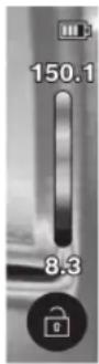
To determine the temperature of a specific area, move the measuring device so that the reticle with temperature display (m) is exactly at the desired point/location. In automatic mode, the color spectrum of the temperature scale is always distributed uniformly (= linearly) between the maximum and minimum temperatures.
The measuring device displays all temperatures measured in the measurement area in relation to each other. When temperatures are shown in blue on the temperature scale, it only means they are the lowest in the current measurement area. The temperature of these blue areas can nevertheless be high enough to cause injury. For this reason, always rely on the temperatures indicated above and below the scale or directly under the reticle.
Functions
Observe the information on navigating the different menus (see "Navigating the different menus", Page 33)

Illumination of the object to be measured
The measuring device is equipped with an illumination LED (4). The illumination LED is intended to illuminate the direct measurement area for taking photos. It should not be used as a permanent light source.
To activate/deactivate the illumination LED, call up the left sidebar. Navigate to the menu option / and confirm your selection. The status bar indicates when the illumination LED is activated.
To avoid affecting measurement accuracy, the LED automatically turns off after 2 minutes.
You can set the automatic shutdown delay under .
Overlay of thermal image and real image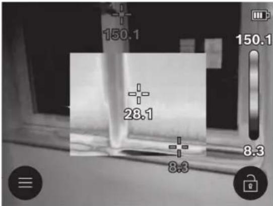
For better spatial orientation on the screen, a real image can be superimposed on the thermal image in areas where temperatures are stable.
Note: At a distance of 1 m, the real image and the thermal image are exactly superimposed. At other distances from the measurement object, there is an offset between the real image and the thermal image. This offset can be compensated with dedicated Bosch applications. You will find information about the applications and their compatibilities on the product page of the measuring tool or at www.bosch-professional.com/thermal.
The measuring tool offers the following possibilities:
- 100% infrared image
Only the thermal image is displayed on the screen.
The thermal image is displayed transparently over the real image. This setting allows better object recognition.
To activate/deactivate the setting, call up the left sidebar and scroll through the menu to the option / . Confirm your selection by pressing the center of the multi-function button (17).
- Picture-in-picture
The thermal image is cropped and the real image appears around it. This setting facilitates spatial orientation.
To activate/deactivate the setting, call up the left sidebar and scroll through the menu to the option / . Confirm your selection by pressing the center of the multi-function button (17).
Adaptation of the color representation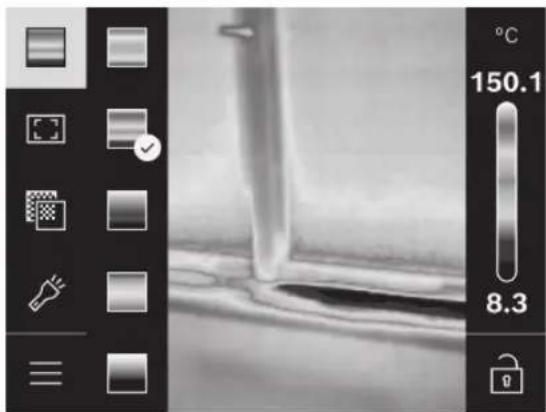
Selecting a certain color palette rather than another can facilitate the analysis of the thermal image and allow a better representation on the screen of objects or a measurement situation. The choice of palette has no influence on the measured temperatures. Only the representation of the temperature values changes.
To change the color palette, call up the left sidebar and scroll through the menu to the option "Color palette". Confirm your selection by pressing the center of the multi-function button (17).
Freezing the temperature scale
The color distribution on the thermal image normally changes automatically according to the measured temperatures, but it can also, if desired, be frozen by pressing the right side and then the center of the multi-function button (17). This allows comparing thermal images recorded at different temperatures (e.g., for locating thermal bridges in living spaces) or excluding an extremely cold or very hot object from a thermal image that could distort the results (for example, a radiator as a hot object when searching for thermal bridges).
To return to automatic mode, call up the right sidebar and press the center of the multi-function button (17). The color display becomes dy-
The dynamics and colors vary continuously based on the measured maximum and minimum temperatures.
Main menu
Call up the left sidebar (see "Navigating the menus", Page 33). To access the main menu, press the center of the multi-function button (17).
This submenu allows you to delete all stored images individually or simultaneously.
-
- (a)
The measuring device stores the emissivity rates of the most common materials. To make searching easier, the values are grouped by category in the emissivity rate catalog. In the menu option, select the appropriate category and then the material. If you know the exact emissivity rate of your measurement object, you can also enter it directly as a numerical value in the menu option.
• (b)
This parameter improves the measurement result for materials with low emissivity (= highly reflective materials). In certain situations (especially indoors), the reflected temperature corresponds to the ambient temperature. It is advisable to change this parameter when objects with large temperature differences are near highly reflective objects. To do this, press the left or right side of the multi-function button (17).
-
To ensure high accuracy over the entire measurement range, there are 2 temperature ranges for measurements. In the measurement function, the device automatically selects the appropriate temperature range based on the temperature distribution in the thermal image. It evaluates the number of measurement values that exceed a given temperature threshold. For measuring very small but very hot objects, the device may select the low temperature range, which is inappropriate for high temperatures. This is recognizable by the symbol \~ in front of the temperature display. In such cases, switch to the measurement function (<100 °C ... 450 °C> or <-20 °C ... 100 °C>) where the color distribution corresponds to the set temperature range. On the scale, the setting is marked by an up or down arrow.
-
• (m): /
The point appears at the center of the thermal image; it indicates the temperature measured at that location.
The hottest point (= measuring pixel) is marked by a red reticle on the thermal image. This facilitates
the search for critical points (e.g., loose terminal in a control cabinet).
The coldest point (= measuring pixel) is marked by a blue reticle on the thermal image. This facilitates the search for critical points (e.g., insulation defect on a window).
The average temperature (c) is displayed at the top left of the thermal image (average temperature of all measured values on the thermal image). This can facilitate the determination of the reflected temperature.
This menu option allows you to adjust the brightness of the screen.
This menu option allows you to set the time interval after which the LED light automatically turns off if no key is pressed.
This menu option allows you to set the time interval after which the measuring device automatically shuts down if no key is pressed. You can also disable the automatic shutdown by selecting the setting option .
This submenu allows you not only to set the time and date but also to modify the display format of the time and date.
This menu option allows you to select the display language.
This menu option allows you to reset the measuring device and permanently erase all data. This may take several minutes. Press the right side of the multifunction button (17) to erase all files or the left side of the multifunction button (17) to cancel the operation.
This submenu provides information about the measuring device. The serial number of the device and the installed software version will then appear.
You will also find other information about the measuring device and software updates here.
To exit any menu and return to the standard screen, you can also use the Measure button (6).
Software update for the measuring device
If necessary, you can update the software of the measuring device via the USB Type-C® interface.
For more information, visit: www.bosch-professional.com/thermal.
Documentation of measurement results
Storing measurement results
The measuring device starts measuring immediately after being switched on and continues to measure until it is switched off.
To store an image, point the camera at the desired measuring object and press the Measure button (6). The image is saved in the internal memory of the measuring device. The image is frozen and remains displayed on the screen. This allows you to observe it carefully and possibly correct it (for example, by changing the color palette). If you do not wish to store the frozen image, return to measuring mode by pressing the Measure button (6). To save the image in the internal memory of the measuring device, press the center of the multi-function button (17).
Displaying stored images
To display the thermal images in memory, proceed as follows:
- Press the multi-function button (17) again immediately after storing. A preview of the last stored photos appears on the screen.
- You can also display the stored photos by selecting the menu option.
- To switch between stored thermal images, press the left or right side of the multi-function button (17).
In addition to the thermal image, the real image is always stored. To display it, press the top or bottom of the multi-function button (17).
After 5 seconds, the full-screen view appears. In the full-screen view, the title bar disappears so that you can see all the details of the thermal image.
You can switch between views by pressing the top or bottom of the multi-function button (17).
Deleting stored images
To delete individual thermal images or all thermal images at once, press the center of the multi-function button (17). A submenu opens.
- It allows you to specify whether you want to delete only this image or all images. Confirm your selection by pressing the center of the multi-function button (17). If you select , you have the choice
between and . Confirm your selection by pressing the center of the multi-function button (17).
- This submenu also allows you to display information about the emissivity and reflected temperature.
Image data fragments that allow images to be reconstructed remain in memory. To permanently delete images, select in the main menu
→ .
Data transfer
Data transfer via USB port
Open the cover (11) of the USB Type-C® port. Connect the USB Type-C® port (12) of the measuring tool to your computer using the supplied USB Type-C® cable (16).
Now switch on the measuring tool using the On/Off button (18).
Open the file explorer on your computer and select the drive GTC_450. The saved files can be copied from the internal memory of the measuring tool, moved to your computer, or deleted.
After completing the desired operation, disconnect the drive from the computer and switch off the measuring tool with the On/Off button (18).
Caution: Before removing the drive, first disconnect it from your operating system using the recommended ejection procedure (the "safely remove hardware" function), otherwise the internal memory of the measuring tool may be damaged.
Remove the USB Type-C® cable and close the cover (11).
Always keep the protective cover of the USB port closed to prevent dirt or water from entering the housing.
Note: Only connect the measuring tool to a computer via the USB port. The measuring tool may be damaged if connected to other devices.
Note: The USB Type-C® port is only for data transfer. It cannot be used to charge batteries or rechargeable batteries.
Post-editing of thermal images
You can post-edit the saved thermal images with dedicated Bosch apps. You can find information about the apps and their compatibility on the product page of the measuring tool or at www.bosch-professional.com/thermal.
Faults – Causes and Remedies
If a malfunction occurs, the measuring tool switches off and restarts automatically, after which it can be used normally again. In the event of persistent malfunctions or faults, use the overview below to resolve the issue.
Fault Cause Remedy
The measuring tool cannot be switched on. Battery/rechargeable battery discharged Charge the battery or replace the batteries.
38 | English
Fault Cause Remedy
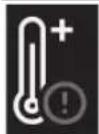
The measuring tool cannot be connected to a computer (PC).
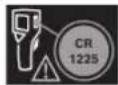
Battery/rechargeable battery defective Replace the battery or rechargeable battery.
Battery/rechargeable battery too hot or too cold Allow the battery/rechargeable battery to reach room temperature or replace it.
Measuring tool too hot or too cold Allow the measuring tool to reach room temperature.
USB port or USB cable defective Check whether the measuring tool can be connected to another computer. If not, send the measuring tool to an authorized Bosch after-sales service center.
Note: Always use the supplied USB cable.
Button cell empty Replace the button cell (see "Replacing the button cell (see figure C)", page 39). Confirm the replacement with "OK" by pressing the center of the multi-function button (17).
Definitions
For more information, visit www.bosch-professional.com/thermal.
Infrared thermal radiation
Infrared thermal radiation refers to the electromagnetic radiation emitted by every body above 0 Kelvin (-273 °C). The intensity of the radiation depends on the temperature and the emissivity of the body.
Emissivity
The emissivity of an object depends on the nature of the material and its surface structure. It indicates how much infrared thermal radiation the object emits compared to an ideal black body (emissivity ε = 1). Its value can range between 0 and 1.
Thermal bridge
A thermal bridge refers to a location on an exterior wall of a building where significant heat loss occurs. Thermal bridges increase the risk of mold formation.
Reflected temperature/reflectivity of an object
Reflected temperature refers to thermal radiation that does not originate from the object itself. Depending on the structure and material, ambient thermal radiation reflects off the object being measured and distorts the temperature measurement result.
Distance to the measurement object
The distance between the measurement object and the measuring device affects the surface area covered by each pixel. The farther the measuring device is from the object, the larger the objects that can be captured.
the measuring device is from the object, the larger the objects that can be captured.
| Distance (m) Taille des pixels infrarouges (mm) | Largeur × hauteur de la zone de mesure infrarouge (m) |
| 0,30 1,14 ~ 0,29 × 0,22 | |
| 0,55 2,08 ~ 0,53 × 0,40 | |
| 1,00 3,79 ~ 0,97 × 0,73 | |
| 2,00 7,58 ~ 1,94 × 1,46 | |
| 5,00 18,95 ~ 4,85 × 3,64 |
Maintenance and After-Sales Service
Cleaning and maintenance
Only transport and store the measuring device in a suitable container, e.g., in its original packaging.
Keep the measuring device clean. A dirty infrared sensor (5) can affect measurement accuracy. During cleaning, no liquid must enter the measuring device.
Do not attempt to remove dirt from the infrared sensor (5), the camera (3), the illumination LED (4), or the laser beam exit opening (2) with a pointed object. Do not wipe the infrared sensor or the camera (risk of scratching).
Clean the area around the laser beam exit opening regularly, avoiding lint.
If you wish to have your measuring tool recalibrated, send it to an authorized Bosch after-sales service center. If the measuring tool needs repair, return it in its original packaging.
The measuring tool contains no user-serviceable or replaceable parts. The measuring tool may be damaged if the housing is opened.
Replacing the button battery (see figure C)
Open the cover (11).
Unscrew the screw (10) of the button battery holder. Remove the button battery holder (9) from the measuring tool. Replace the button battery. Reinsert the button battery holder and retighten the screw (10).
After-sales service and user advice
Our after-sales service answers your questions regarding the repair and maintenance of your product and spare parts. Exploded views and information on spare parts can also be found at: www.bosch-pt.com
The Bosch user advice team is at your disposal to answer your questions about our products and their accessories.
For any inquiry or spare parts order, please always specify the ten-digit article number indicated on the product's rating plate.
France
Repairing a Bosch tool has never been easier, and in less than 5 days, thanks to SAV DIRECT, our online return form available on our website www.bosch-pt.fr under the Services section. You will also find our online spare parts shop where you can place your orders directly.
If you are a user, contact: Bosch Power Tools Customer Service
Tel.: 09 70 82 12 26 (Non-premium number at local call rate)
E-Mail: sav.outillage-electroportatif@fr.bosch.com
If you are a reseller, contact:
Robert Bosch (France) S.A.S.
Service Après-Vente Electroportatif
126, rue de Stalingrad
93705 DRANCY Cédex
Tel.: (01) 43119006
E-Mail: sav-bosch.outillage@fr.bosch.com
You will find other service addresses at:
www.bosch-pt.com/serviceaddresses
Transport
The recommended Lithium-ion batteries are subject to the regulations for the transport of dangerous goods. The user can transport the batteries by road without further measures.
When shipping by third parties (e.g., air transport or forwarding company), the specific measures for packaging and labeling must be observed. In such a case, when preparing the shipment, it is imperative to consult an expert in the transport of dangerous goods.
Only ship the batteries if the housing is not damaged. Cover open contacts and pack the battery so that it does not move around in the packaging. Please also observe any additional national regulations.
Only ship the battery if the housing is not damaged. Cover any exposed contacts and pack the battery so it cannot move around in the packaging. Please also observe any additional regulations that may apply in your country.
Waste disposal

Please return measuring tools, batteries/rechargeable batteries, accessories, and packaging to an environmentally friendly recycling center.
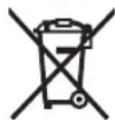
Do not dispose of measuring tools and batteries/rechargeable batteries with household waste!
Only for EU countries:
Out-of-service measuring instruments and defective or used batteries/rechargeable batteries must be disposed of separately. Use the designated collection systems.
If not disposed of correctly, waste electrical and electronic equipment can have harmful effects on the environment and human health due to the possible presence of hazardous substances.
Rechargeable batteries/batteries:
Li-Ion:
Please observe the information in the Transport chapter (see "Transport", Page 39).
Valid only for France:

Collection points at www.quefairedemesdechets.fr
Spanish
Safety instructions

Read and observe all instructions to work safely and without risk with the measuring tool. If the measuring tool is not used in accordance with these instructions,
the safety measures integrated in the measuring tool may be impaired. Never tamper with the warning signs on the measuring tool. KEEP THESE INSTRUCTIONS SAFE AND HAND THEM OVER WITH THE MEASURING TOOL.
40 | Spanish
- Caution – if handling or adjustment devices other than those specified in this document are used, or if other procedures are followed, this may lead to dangerous exposure to radiation. The measuring tool is supplied with a laser warning label (marked on the representation of the measuring tool on the illustrated page). If the text on the laser warning label is not in your country's language, cover it with the adhesive label supplied in your country's language before first use.

Do not point the laser beam at people or animals, and do not look directly into the laser beam or its reflection. This can dazzle people, cause accidents, or damage the eye.
- If laser radiation strikes the eye, consciously close your eyes and immediately move your head out of the beam.
▶ Do not make any modifications to the laser equipment.
▶ Do not use the laser viewing glasses (accessory) as protective goggles. Laser viewing glasses are used to better detect the laser beam; however, they do not protect against laser radiation.
Do not use the laser viewing glasses (accessory) as sunglasses or while driving. Laser viewing glasses do not provide full UV protection and reduce color perception.
Only have the measuring tool repaired by qualified technical personnel and only with original spare parts. This ensures the safety of the measuring tool is maintained.
Do not allow children to use the laser measuring tool without supervision. They could unintentionally dazzle other people or themselves.
Do not work with the measuring tool in a potentially explosive environment where flammable liquids, gases, or dusts are present. The measuring tool can produce sparks and ignite dust or vapors.
▶ Do not modify or open the battery. This could cause a short circuit.
If the battery is damaged or used improperly, vapors may be emitted. The battery can burn or explode. In such a case, seek fresh air and consult a doctor if you feel unwell. The vapors can irritate the respiratory tract.
In the event of incorrect use or a damaged battery, flammable liquid may escape from the battery. Avoid contact with it. In case of accidental contact, rinse thoroughly with water. If the liquid comes into contact with the eyes, also seek medical attention immediately. Battery liquid can irritate the skin or cause burns.
Using sharp objects such as nails or screwdrivers, or the influence of external force, can damage the battery. An internal short circuit can occur, and the battery can burn, smoke, explode, or overheat. ▶ If you do not use the battery, store it separately from paper clips, coins, keys, nails, screws, or other metal objects that could bridge its contacts. Short-circuiting the battery contacts can cause burns or a fire. ▶ Use the battery only in products from the manufacturer. Only in this way is the battery protected against dangerous overload. Charge batteries only with chargers recommended by the manufacturer. There is a risk of fire when attempting to charge batteries of a different type than the one intended for the charger.

Protect the battery from excessive heat, as well as, for example, prolonged exposure to the sun, dirt, fire, water, or moisture. There is a risk of explosion and short circuit.

WARNING

Make sure that the button cell does not get into the hands of children. Button cells are dangerous.
Button cells must never be swallowed or inserted into other body orifices. If there is a suspicion that the button cell has been swallowed or inserted into another body opening, seek medical attention immediately. Swallowing a button cell can cause serious internal burns and death within 2 hours. When changing the button cell, pay attention to correct replacement of the button cell. There is a risk of explosion. ▶ Use only the button cells named in these operating instructions. Do not use other button cells or other power sources. Do not attempt to recharge button cells and do not short-circuit the button cell. The button cell can leak, explode, burn, or injure people. ▶ Remove and dispose of button cells properly. Discharged button cells can leak and thereby damage the product or injure people. Do not let the button cell overheat and do not throw it into a fire. The button cell can leak, explode, burn, or injure people. Do not damage the button cell and do not disassemble the button cell. The button cell can leak, explode, burn, or injure people.
Make sure that a damaged button cell battery does not come into contact with water. Lithium spilled in contact with water can generate hydrogen and therefore lead to fire, explosion, or personal injury. Do not continue using the measuring tool if the button cell battery compartment cannot be closed properly and completely; remove the button cell battery and have the measuring tool repaired. High temperature differences in a thermal image can cause even high temperatures to be displayed in a color associated with low temperatures. Contact with such a surface can cause burns. Correct temperature measurements are only possible if the set emissivity and the emissivity of the object match. Objects may be indicated at a temperature that is too high or too low, which can result in a risk in the case of contact. Do not point the measuring tool directly at the sun or at high-power CO₂ lasers. This can damage the detector. ▶ Protect the measuring tool, especially the camera and infrared lens areas, from moisture, snow, dust, and dirt. The receiver lens may be fogged or dirty and falsify measurement results. Incorrect settings of the tool as well as other atmospheric influencing factors can lead to incorrect measurements. Objects may be indicated at a temperature that is too high or too low, which can result in a risk in the case of contact.
Product Description and Service
Please observe the figures in the front part of the operating instructions.
Intended Use
This thermal imaging camera is designed for non-contact measurement of surface temperatures.
The displayed thermal image shows the temperature distribution of the camera's field of view and thus allows temperature differences to be shown in different colors.
With proper use, surfaces and objects can be examined without contact to detect temperature differences or anomalies, in order to make components and/or any weak points visible, among others:
- thermal insulation and insulation (e.g., locating thermal bridges),
- active heating and hot water pipes (e.g., underfloor heating) in floors and walls,
- overheated electrical components (e.g., fuses or terminals),
- defective or damaged machine parts (e.g., overheating due to defective ball bearings).
The measuring tool is not suitable for measuring the temperature of gases.
The measuring tool must not be used for human medical purposes.
Please inform yourself about veterinary use at www.bosch-professional.com/thermal.
The measuring tool is suitable for use indoors and outdoors.
This product is a consumer laser product conforming to EN 50689.
The light from this measuring device is intended to illuminate the direct work area of the measuring device for image capture and does not serve as permanent work light.
The laser point must not be used as a laser pointer. It is used exclusively to mark the measuring surface.
Represented components
The numbering of the components refers to the image of the measuring device on the illustrated page.
(1) Protective cap (2) Laser beam exit opening (3) Visual camera (4) Work light (5) Infrared sensor (6) Pause/Start measurement button (7) Battery compartment (8) Laser warning label (9) Button cell battery holder
(10) Button cell battery holder screw
(11) Cover for USB socket and button cell battery holder
(12) USB Type-C ®a) socket
(13) Laser button
(14) Battery/ battery adapter release button
(15) Battery b
(16) USB Type-C ®b cable
(17) Multifunction button
(18) On/off button/back button
(19) Display
(20) Serial number
(21) Battery adapter cover
(22) Batteries b)
(23) Closing cap for battery adapter
a) USB Type-C® and USB-C® are trademarks of USB Implementers Forum.
b) The accessories described and illustrated do not correspond to the material supplied as standard.
Indicating elements
(a) Emissivity indicator
42 | English
(b) Reflected temperature indicator (c) Average temperature indicator (d) Memory full symbol (e) Work light symbol (f) Laser symbol (g) Charge status indicator (h) Maximum surface temperature indicator in the measuring range
(i) Scale (j) Minimum surface temperature indicator in the measuring range (k) Fix temperature scale symbol (I) Cold spot indicator (example) (m) Reticle with temperature indicator (n) Hot spot indicator (example) (o) Menu symbol
Technical data
| Cámara de imágenes térmicas GTC 12V-450-13 | |
| Número de artículo | 3 601 K83 900 |
| Resolución del sensor de infrarrojos 256 × 192 px | |
| Sensibilidad térmicA | ≤ 50 mK |
| Margen espectral 8–14 μm | |
| Campo visual (FOV) A | 55,6° × 42° |
| Resolución espacial (IFOV) 3,79 mrad | |
| Distancia\ de\ enfoqueA) | ≥ 0,5 m |
| Foco fijo | |
| Frecuencia de repetición de imagen térmica ≤ 9 Hz | |
| Margen de medición de temperatura superficial A) | -20 ... +450 °C |
| Exactitud de medición de la temperatura superficial (A)(B)(C) | |
| >0 °C ... ≤ +100 °C D) | ±2 °C |
| >+100 °CE J | ±2 % |
| Resolución de temperatura 0,1 °C | |
| Tipo de pantalla Pantalla plana (TFT) | |
| Tamaño de la pantalla 2,8" | |
| Resolución de la pantalla 480 × 360 px | |
| Resolución de cámara visual integrada 2 MP (640 × 480 px) | |
| Formato de imagen .jpg | |
| Elementos memorizados por proceso de memorización 1 × imagen térmica (captura de pantalla),1 × imagen real visual, incl. valores de temperatura (metadatos) | |
| Cantidad máxima de imágenes en la memoria interna de imágenes | 500 |
| Altura de aplicación máx. sobre la altura de referencia 2000 m | |
| Grado de contaminación según IEC 61010-1 2 | F) |
| Humedad relativa del aire máx. A | 90 % |
| Clase de láser 2 | |
| Tipo de láser | < 1 mW, 645–660 nm |
| Divergencia del rayo láser | 1,5 mrad (ángulo completo) |
| Suministro de corriente | |
| - Acumulador (iones de litio) | 12 V |
| - Pilas alcalinas de manganeso (con adaptador de pilas) | 4 × 1,5 V LR6 (AA) |
| - Acumuladores (NiMH, con adaptador de batería) | 4 × 1,2 V HR6 (AA) |
| Duración\ del\ servicioG) | |
Thermal imaging camera GTC 12V-450-13
| - Acumulador (iones de litio) H)1) | 8 h |
| - Pilas (alcalinas-manganeso) 4 h | |
| Alimentación de energía, tiempo del sistema CR1225 (pila de litio de 3 V) | |
| USB por defecto 2.0 | |
| Interfaz USB USB Type-C® | |
| Peso1) | 0,354 kg |
| Medidas (longitud × ancho × altura) K) | 89 × 79 × 209 mm |
| Tipo de protección (excepto el acumulador, en posición vertical) | IP54 |
| Temperatura ambiente recomendada durante la carga 0 °C ... +35 °C | |
| Temperaturas ambientes permitidas | |
| - durante el funcionamiento -10 °C ... +50 °C | |
| - en caso de almacenamiento con acumulador -20 °C ... +50 °C | |
| - en caso de almacenamiento sin acumulador -20 °C ... +70 °C | |
| Acumuladores recomendados GBA 12V... | |
| Cargadores recomendados GAL 12... | GAX 18... |
A) according to VDI 5585 standard (average value) B) With an ambient temperature of 20–23 °C and an emissivity of ≥ 0.95, measuring distance: 1 m, operating time: > 5 min, aperture of 150 mm, with work light off and laser off C) plus application-dependent divergence (e.g., reflection, distance, ambient temperature) D) Applies to the center point, for the remaining pixels additionally ±1 °C E) Applies to the center point, for the remaining pixels additionally ±1 % F) Only non-conductive soiling occurs, however occasional temporary conductivity caused by condensation is expected. G) With work light off and medium screen brightness H) depending on the battery used I) at an ambient temperature of 20-30 °C J) Weight without battery/battery adapter/batteries K) With GBA 12V 2.0Ah or battery adapter For unambiguous identification of your measuring device, the serial number (20) on the rating plate is used.
Power supply for the measuring tool
The measuring tool can be operated with a Bosch lithium-ion rechargeable battery, with commercially available batteries, or with commercially available NiMH rechargeable batteries.
Operation with rechargeable battery (see figure A)
▶ Use only the chargers listed in the technical data. Only these chargers are specially matched to the lithium-ion batteries used in your measuring tool.
Note: Lithium-ion rechargeable batteries are delivered partially charged due to international transport regulations. To achieve full battery capacity, fully charge the battery before first use.
To insert the charged battery (15), slide it into the battery compartment (7) until it audibly clicks into place.
To remove the battery (15), press the release buttons (14) and pull the battery out of the compartment (7). Do not use force.
Operation with batteries (see figure B)
For operation of the measuring tool, alkaline manganese batteries or NiMH rechargeable batteries are recommended.
The batteries are placed in the battery adapter.
The battery adapter is intended for use exclusively with the designated Bosch measuring tools and must not be used with power tools.
To insert the batteries, push the sleeve (21) of the battery adapter into the battery compartment (7). Insert the batteries into the sleeve as shown in the figure on the closing cap (23). Place the cap onto the sleeve until it clicks into place.
To remove the batteries (22), press the release buttons (14) on the closing cap (23) and pull it out.
Remove the batteries. To remove the inner sleeve (21) from the battery compartment, grasp it and pull it out of the measuring tool while gently pressing the side wall.
Always replace all batteries or rechargeable batteries at the same time. Only use batteries or rechargeable batteries from the same manufacturer and with the same capacity.
▶ Remove the batteries or rechargeable batteries from the measuring tool if it will not be used for an extended period. Batteries and rechargeable batteries can corrode if stored in the measuring tool for a long time.
Tips for optimal handling of the rechargeable battery
Protect the rechargeable battery from moisture and water.
Only store the rechargeable battery within a temperature range of -20°C to 50°C. For example, do not leave the rechargeable battery in the car in summer.
If the operating time of the rechargeable battery becomes very short after recharging, this indicates that it is exhausted and must be replaced.
Observe the notes on disposal.
Operation
▶ Protect the measuring tool from moisture and direct sunlight. Do not expose the measuring tool to extreme temperatures or temperature fluctuations. Do not leave it in the car for a long time, for example. In case of strong temperature fluctuations, allow the measuring tool to stabilize first before putting it into operation. Extreme temperatures or sudden temperature changes can affect the accuracy of the measuring tool. Make sure the measuring tool acclimatizes properly. In case of strong temperature variations, the acclimatization time can take up to 60 minutes. This can be the case, for example, if you store the measuring tool in a cold car and then take a measurement in a heated building. Avoid the measuring tool being knocked or dropped. After strong external influences and in case of functional anomalies, you should have the measuring tool checked by an authorized Bosch after-sales service.
Start-up
On first connection
On first connection of the measuring tool or after resetting the factory settings, some basic settings must be made. Select the desired values by pressing the multifunction button (17) down, up, left, or right. Press the multifunction button (17) in the center to confirm your selection. Once you have confirmed your selection, the next setting is displayed on the screen. The total number and the number of remaining settings are shown in the status bar at the top.
The following basic settings are available:
Switching on/off
Open the protective cap (1) for measurement. During work, make sure that the infrared sensor is not closed or covered.
To turn on the measuring tool, press the on/off button (18). A start-up sequence appears on the display (19). After the start-up sequence, the measuring tool immediately begins measuring and continues to do so continuously until it is turned off.
Note: During the first few minutes, the measuring tool may self-calibrate more frequently because the sensor and the ambient temperature have not yet adapted to each other. The sensor recalibration enables precise measurement.
During this time, the temperature indicator may be marked with the ~ symbol. This effect is intensified by strong fluctuations in the ambient temperature. Therefore, if possible, turn on the measuring tool a few minutes before starting the measurement so that it can thermally stabilize.
To turn off the measuring tool, press the on/off button (18) for more than 1 second. The measuring tool saves all settings and then turns off. Close the protective cap (1) for safe transport of the measuring tool.
In the main menu, you can select whether and after how much time the measuring tool automatically turns off (see "Main menu", page 47).
If the battery or the measuring tool is outside the operating temperature specified in the technical data, the measuring tool automatically turns off after a brief warning (see "Faults – Causes and remedies", page 48). Allow the measuring tool to cool down and then turn it on again.
Navigating the menus
Navigating the menus of the measuring tool:
- Accessing the menu bars: Press the multifunction button (17) in the center or on the left. The menu bars on the right and left appear on the display, with the main menu highlighted.
- Scrolling in the left menu bar/navigating in the main menu: Press the multifunction button (17) up, down, left, or right.
- Switching to the left or right menu bar: Press the multifunction button (17) to the left or right.
- Confirming the selection/accessing a submenu: Press the multifunction button (17) in the center.
- Returning from a submenu to a higher-level menu: Press the Back button (18).
Preparations for measurement
Setting the emissivity for surface temperature measurements
The emissivity of an object depends on the material and structure of its surface. It indicates the amount of infrared heat radiation that the object emits compared to an ideal heat radiator (black body, emissivity ε = 1) and therefore has a value between 0 and 1.
To determine the surface temperature, the natural infrared thermal radiation emitted by the selected object is measured without contact. To obtain correct measurements, the emissivity set on the measuring device must be checked before each measurement and, if necessary, adjusted to the object being measured.
The emissivities preset on the measuring device are reference values.
You can select one of the preset emissivities or enter an exact numerical value. Set the desired emissivity using the <Measurement Parameters
menu> → (see "Main Menu", page 47).
Correct temperature measurements are only possible if the set emissivity and the emissivity of the object match.
The lower the emissivity, the greater the influence of reflected temperature on the measurement result. Therefore, always adjust the reflected temperature when changing the emissivity. Set the reflected temperature using the menu →
(see "Main Menu", page 47).
Any temperature difference displayed by the measuring device may be due to different temperatures and/or different emissivities. In the case of very different emissivities, the displayed temperature differences may differ significantly from the real ones.
If there are several objects of different materials or structures in the measuring range, the displayed temperature values are only accurate for objects that correspond to the set emissivity. For all other objects (with other emissivities), the displayed color differences can be used as an indication of temperature relationships.
Notes on measurement conditions
Highly reflective or shiny surfaces (e.g., tiles or shiny metals) can falsify or greatly alter the displayed results. If necessary, cover the measuring surface with matte, dark-colored, thermally conductive adhesive tape. Wait a brief moment for the tape to reach the surface temperature.
In the case of reflective surfaces, ensure that the measuring angle is favorable so that reflected heat radiation from other objects does not falsify the result. For example, when measuring vertically from the front, the reflection of your own radiated body heat can affect the measurement. Thus, on a flat surface, the contours and temperature of your body (reflected value) could be displayed, which do not correspond to the actual temperature of the measured surface (emitted value or actual surface value).
In principle, it is not possible to take measurements through transparent materials (e.g., glass or transparent plastic).
Measurement results are more accurate and reliable the better and more stable the measurement conditions are. In this case, not only strong temperature fluctuations in the ambient conditions are relevant, but also strong fluctuations in the temperature of the measured object can affect accuracy.
Infrared temperature measurement is affected by the presence of smoke, vapor, high air humidity, or dust in the air.
Instructions for better measurement accuracy:
- Get as close as possible to the measurement object to minimize interfering factors between you and the measurement surface.
- Therefore, ventilate indoor spaces before taking measurements, especially if the air is contaminated or contains too much vapor. After ventilating the room, wait a moment until it returns to its normal temperature.
Marking the measurement point
Do not point the laser beam at people or animals, and do not look directly into the laser beam, even from a great distance.
The measuring device is equipped with a laser to mark the measurement point.
Press and hold the laser button (13). The laser symbol (f) is shown in the status bar, and a red circle appears around the reticle cross (m). The overlay of the laser and the reticle cross is exactly coincident at a distance of 1 meter. If you release the laser button (13), the laser turns off.
Temperature assignment according to the scale
On the right side of the display, the scale (i) is shown. The values at the top and bottom are oriented to the maximum temperature (h) and minimum temperature (j) recorded in the thermal image. For the scale, 99.99% of the total pixels are evaluated. The assignment of a color to a temperature value in the image is distributed uniformly (linearly).
With the help of the different color shades, temperatures within these two limit values can be assigned. For example, a temperature that lies exactly between the maximum and minimum value is assigned to the middle color range of the scale.
To determine the temperature of a specific area, move the measuring device so that the reticle cross
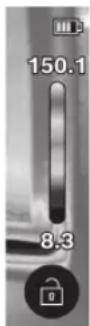
so that the temperature indication (m) is directed at the desired point or area. In automatic adjustment, the color spectrum of the scale is always distributed linearly (= uniformly) across the entire measurement range within the maximum and minimum temperature.
The measuring tool displays all measured temperatures in the measurement range in relation to each other. If the heat of an area, for example in a color representation, appears bluish in the color palette, this means that the blue areas belong to the coldest measured values in the current measurement range. However, these areas may still be within a temperature range that can cause injury under certain circumstances. Therefore, always pay attention to the temperatures indicated on the scale or directly on the reticle.
Functions
Observe the information regarding navigation in the various menus (see "Navigating the menus", page 44)

Illumination of the measurement object
The measuring tool is equipped with a work light (4). It is intended to illuminate the direct work area of the measuring tool for image capture and does not serve as a permanent work light.
To switch the work light on/off, access the left sidebar. Scroll to the menu option / and confirm your selection. If the work light is switched on, it is shown in the status bar.
The light switches off automatically after 2 minutes to avoid affecting measurement accuracy.
The automatic switch-off time can be adjusted in the menu under .
Overlay of thermal and real image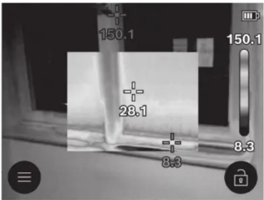
For better orientation (= spatial assignment of the displayed thermal image), a visual real image can be added for balanced temperature ranges.
Note: The exact overlay of real and thermal image takes place at a distance of 1 m. With different distances to the measurement object, there is in principle an offset between real and thermal image. This offset can be compensated with special Bosch applications. Information about the applications and their compatibilities can be found on the product page of the measuring tool or at www.bosch-professional.com/thermal.
The measuring tool offers you the following possibilities: - 100% infrared image: Only the thermal image is displayed.
transparency

The displayed thermal image is placed transparently over the real image. This makes it easier to recognize objects.
To activate/deactivate the adjustment, access the left sidebar and scroll to the menu option / . Confirm your selection by pressing the multifunction key (17) in the center.

The displayed thermal image is cropped and the surrounding area is shown as a real image. This setting improves the local assignment of the measurement margin.
To activate/deactivate the adjustment, access the left sidebar and scroll to the menu option / . Confirm your selection by pressing the multifunction key (17) in the center.
Adaptation of the color representation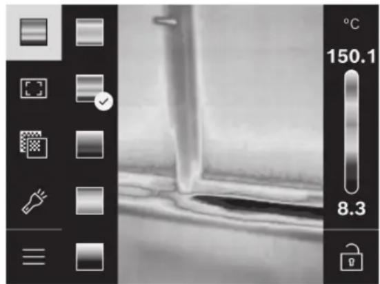
Depending on the measurement situation, different color palettes can facilitate the analysis of the thermal image and represent objects or states of affairs more clearly on the screen. Therefore, measured temperatures are not affected. Only the representation of the temperature values is modified.
To change the color palette, access the sidebar and scroll to the menu option "Color palette". Confirm
your selection by pressing the multifunction key (17) in the center.
Fixing the scale
The color distribution in the thermal image is adjusted automatically; however, it can be fixed by pressing the multifunction key (17) to the right and then in the center. This allows comparability of thermal images taken under different temperature conditions (e.g., when checking for thermal bridges in various rooms) or hiding an extremely cold or hot object in the thermal image that would otherwise distort it (e.g., heaters as hot objects in the search for thermal bridges).
To return the scale to automatic, access the right sidebar and press the multifunction key (17) in the center. The temperatures now behave dynamically again and adapt to the measured minimum and maximum values.
Main menu
Access the left sidebar (see "Navigating the menus", Page 44). To access the main menu, press the multifunction key (17) in the center.
- In this menu option, you can delete saved images individually or all at once.
- (a)
For some of the most common materials, stored emissivities are available for selection. To make searching easier, the values are grouped in the emissivity catalog. First select the appropriate category in the menu option and then the appropriate material. If you know the exact emissivity of your measurement object, you can also set it as a numerical value in the menu option.
• (b)
Adjusting this parameter can improve the measurement result, especially for materials with low emissivity (= high reflection). In some situations (especially indoors), the reflected temperature is equal to the ambient temperature. If objects with very different temperatures near highly reflective objects could affect the measurement, you should adapt this value. To do this, press the multifunction key (17) on the left or right.
-
Note: To ensure high accuracy over the entire measurement range, measurement is performed in 2 temperature ranges. In the measurement function, the measuring tool automatically selects the appropriate temperature range based on the temperature distribution in the thermal image. It evaluates how many measurement values exceed a certain temperature threshold. If very small but hot objects are to be measured, the low temperature range can be selected, which is not suitable for high temperatures. It is recognized by the symbol \~ in front of the temperature indication. In this case, switch to the measurement function <100 °C ... 450 °C> or <-20 °C ... 100 °C>, in which the color distribution corresponds to the adjusted temperature range. The setting is marked on the scale with an upward or downward arrow.
ra, which is not suitable for high temperatures. It is recognized by the symbol \~ in front of the temperature indication. In this case, switch to the measurement function <100 °C ... 450 °C> or <-20 °C ... 100 °C>, in which the color distribution corresponds to the adjusted temperature range. The setting is marked on the scale with an upward or downward arrow.
-
- (m): /
The point is displayed in the center of the thermal image and shows you the value of the temperature measured at this location.
• (n): /
The hottest point (= measurement pixel) is marked by a red reticle cross in the thermal image. This makes it easier to find critical points (e.g., loose contact terminal in the distribution cabinet).
- (I): /
The coldest point (= measurement pixel) is marked by a blue reticle cross in the thermal image. This makes it easier to find critical points (e.g., a leak in the window).
- (i): /
The average temperature (°C) is displayed in the upper left corner of the thermal image (average temperature of all measured values in the thermal image). This can help you determine the reflected temperature.
Tool settings>
In this menu option, you can adjust the brightness of the screen illumination.
In this menu option, you can select the time interval for the automatic shutdown of the work light if no key is pressed.
In this menu option, you can select the time interval after which the measuring device should automatically shut down if no key is pressed. You can also disable the automatic shutdown by selecting the setting .
In this submenu, you can change not only the time and date, but also their respective formats.
In this menu option, you can select the language used in the display.
In this menu option, you can reset the measuring device to factory settings and permanently delete all data. This may take several minutes depending on the circumstances. Press the multifunction key (17) on the right to delete all files, or the multifunction key (17) on the left to cancel the process.
48 | Spanish
-
In this menu option you can request information about the measuring device. There you will find the serial number of the measuring device and the version of the installed software. In addition, you will find more information about the measuring device as well as about the software update.
To exit any menu and return to the standard display, you can also press the measurement key (6).
Software update of the measuring tool
If necessary, you can update the software of the measuring tool via the USB Type-C® interface. You will find information about this at: www.bosch-professional.com/thermal.
Documentation of measurement results
Storing measurement results
Immediately after connection, the measuring device starts measuring and continues permanently until disconnection.
To save an image, aim the camera at the desired target and press the measurement key (6). The image is saved in the internal memory of the measuring device. The measurement freezes and is displayed on the screen. This allows you to thoroughly view the image and make subsequent adjustments (e.g., in the color palette). If you do not want to save the frozen image, press the measurement key (6) to restart the measurement mode. If you want to save the image in the internal memory of the measuring device, press the multifunction key (17) in the center.
Viewing stored images
To view the stored thermal images, proceed as follows:
- Immediately after saving, press the multifunction key (17) in the center again. The preview of the last saved photo appears on the screen.
- Alternatively, you can access the saved photos in the menu option .
- To switch between the stored thermal images, press the multifunction key (17) to the right or left.
In addition to the thermal image, the visual image is also stored. To call it up, press the multifunction key (17) up or down.
After 5 s, the measuring tool switches to full-screen view. In full-screen view, the title bar disappears so that you can see all the details of the thermal image.
Pressing the multifunction key (17) up and down allows you to change the views.
Deleting stored images
To delete one or all thermal images, press the multifunction key (17) in the center. A submenu opens.
- Here you can select whether you want to delete only this image or all images. Confirm the selection with the multifunction key (17) in the center.
In the selection, you can choose between and . Confirm the selection with the multifunction key (17) in the center.
- In this submenu, you can also view information about the emissivity and the reflected temperature.
Data fragments of the images remain in the memory and could be reconstructed. For permanent deletion, select in the main menu <Tool settings
> → .
Data transfer
Data transfer via USB interface
Open the cover (11) of the USB Type-C® socket. Connect the USB Type-C® socket (12) of the measuring tool to your computer using the USB Type-C® cable (16) supplied.
Connect the measuring tool only with the on/off switch (18).
Open the file browser on your computer and select the drive GTC_450. The stored files can be copied from the internal memory of the measuring tool, transferred to your computer, or deleted.
Once the desired process has been completed, disconnect the unit from the computer as instructed, and then switch off the measuring tool again using the on/off button (18).
Caution: Always disconnect the unit from your operating system first (eject the unit), otherwise the internal memory of the measuring tool may be damaged.
Remove the USB Type-C® cable and close the cover (11).
Always keep the USB interface cover closed to prevent dust and water splashes from entering the housing.
Note: Connect the measuring tool via USB exclusively to a computer. The measuring tool may be damaged when connected to other devices.
Note: The USB Type-C® interface is exclusively for data transmission. Batteries and rechargeable batteries cannot be charged through this interface.
Post-processing of thermal images
You can perform post-processing of stored thermal images with special Bosch applications. Information about the applications and their compatibility can be found on the product page of the measuring tool or at www.bosch-professional.com/thermal.
Faults - Causes and remedies
In the event of a malfunction, the measuring tool performs a restart and can then be used again. Otherwise, the following list will help if there are persistent error messages.
Fault Cause Remedy
| No se puede conectar el aparato de medición. | Accumulador vacío/pilas agotadas | Cargue el acumulador o cambie las pilas. | |
 | Fallo de acumulador/pilas Cambie el acumulador o las pilas. | ||
 | Accumulador/pilas demasiado caliente(s) o demasiado frío(frías) | Deje que el acumulador se enfríe o cambie el acumulador respectivamente las pilas. | |
 | Aparato de medición demasiado caliente o demasiado frío | Deje que se atempere el aparato de medición. | |
 | Conexión USB o cable USB averiado | Compruebe si el aparato de medición se puede conectar a otro ordenador. Si no, envíe el aparato de medición a un centro de servicio autorizado de Bosch. | |
| El aparato de medición no se puede conectar con un ordenador. | Indicación: Utilice siempre el cable USB incluido en el volumen de suministro. | ||
 | Pila en forma de botón agotada | Cambie la pila en forma de botón (ver "Cambio de pila en forma de botón (ver figura C)", Página 50). Confirme el cambio con "OK" presionando la tecla multifuncional (17) en el centro. | |
Glossary
Additional information can be found at www.bosch-professional.com/thermal.
Infrared heat radiation
Infrared heat radiation is electromagnetic radiation emitted by every body above 0 Kelvin (-273 °C). The amount of radiation depends on the temperature and emissivity of the body.
Emissivity
The emissivity of an object depends on the material and structure of its surface. It indicates the amount of infrared heat radiation that the object emits compared to an ideal heat radiator (black body, emissivity ε = 1) and therefore has a value between 0 and 1.
Thermal bridge
A thermal bridge is a point in the exterior wall of a building where the construction causes a locally higher heat loss.
Thermal bridges can increase the risk of mold.
Reflected temperature/reflectivity of an object
The reflected temperature is the heat radiation that does not come from the object itself. Depending on the structure and material, ambient radiation is reflected on the object being
measured and thus falsifies the result of the actual temperature.
Distance to the object
The distance between the measuring object and the measuring device influences the size of the area recorded per pixel. With increasing distance from the objects, larger and larger objects can be recorded.
| Distancia (m) Tamaño de píxeles de infra- rojos (mm) | Gama de infrarrojos anchura × altura (m) |
| 0,30 1,14 ~ 0,29 × 0,22 | |
| 0,55 2,08 ~ 0,53 × 0,40 | |
| 1,00 3,79 ~ 0,97 × 0,73 | |
| 2,00 7,58 ~ 1,94 × 1,46 | |
| 5,00 18,95 ~ 4,85 × 3,64 |
Maintenance and service
Maintenance and cleaning
Store and transport the measuring device only in a suitable container such as the original packaging.
Always keep the measuring device clean. A dirty infrared sensor (5) can affect the accuracy of the measurement.
Avoid liquid penetration when cleaning the measuring tool.
Do not attempt to use pointed objects to remove dirt from the infrared sensor (5), the camera (3), the work light (4), or the laser beam exit opening (2). Do not rub the infrared sensor and the camera (risk of scratches).
Regularly clean the area around the laser exit opening, making sure no lint remains.
If you wish to recalibrate your measuring tool, contact an authorized Bosch service center.
For repair, send the measuring tool in its original packaging.
There are no user-serviceable parts inside the measuring tool. Opening the housing halves can destroy the measuring tool.
Replacing the button cell battery (see figure C)
Open the cover (11).
Unscrew the screw (10) from the button cell battery holder. Remove the button cell battery holder (9) from the measuring tool. Replace the button cell battery. Firmly screw the screw (10) back in after placing the button cell battery holder.
Service and customer support
The service department will advise you on questions regarding repair and maintenance of your product, as well as spare parts. Exploded view drawings and information on spare parts can also be obtained at: www.bosch-pt.com
Our team of technical advisors will be happy to assist you with the purchase, application, and adjustment of products and accessories.
For any inquiry or spare parts order, it is essential to provide the 10-digit article number found on the product's nameplate.
Spain
Robert Bosch España S.L.U.
Sales Department Power Tools
C/Hermanos García Noblejas, 19
28037 Madrid
To place your online order for spare parts or to request pickup for the repair of your machine, go to www.herramientasbosch.net.
Customer advisory telephone: 902 531 553
Fax: 902 531554
Mexico
Robert Bosch, S. de R.L. de C.V.
Calle Robert Bosch No. 405
C.P. 50071 Zona Industrial, Toluca – Estado de México
Tel.: (52) 55 528430-62
Tel.: 800 6271286
www.boschherramientas.com.mx
You will find more service addresses at: www.bosch-pt.com/serviceaddresses
Transport
The recommended lithium-ion batteries are subject to the requirements stipulated in the dangerous goods legislation. The batteries can be transported by road by the user without further restrictions. In the case of shipment by third parties (e.g., air transport or transport agency), special requirements regarding packaging and identification must be considered. In this case, a dangerous goods expert should be consulted when preparing the item for shipment.
Only send batteries if their housing is not damaged. If the contacts are not protected, cover them with adhesive tape and pack the battery so that it cannot move inside the packaging. Also observe the applicable national regulations.
Disposal

The measuring tool, the battery or batteries, the accessories, and the packaging should be subjected to a recycling process that respects the environment.
Do not throw measuring devices and batteries into the household waste!
Only for EU countries:
Measuring devices that can no longer be used and defective or used batteries must be disposed of separately. Use the collection systems provided. If disposed of improperly, waste from electrical and electronic equipment can have harmful effects on the environment and human health due to the possible presence of hazardous substances.
Batteries:
Lithium-ion:
Please observe the instructions in the Transport section (see "Transport", Page 50).

The symbol is only valid if it is also found on the product/nameplate.
Portuguese
Safety instructions

All instructions must be read and followed to work safely and without danger with the measuring tool. If the measuring tool is not used in accordance with these instructions, the protections integrated in the measuring tool may be affected. Never allow the warning plates on the measuring tool to become unrecognizable. KEEP THESE INSTRUCTIONS SAFE AND HAND THEM OVER WITH THE MEASURING TOOL IF YOU PASS IT ON TO THIRD PARTIES.
Caution - The use of operating or adjustment devices other than those specified in this document or other procedures may result in dangerous exposure to radiation. The measuring tool is supplied with a laser warning plate (identified in the figure of the measuring tool, which is on the diagram page). If the text on the laser warning plate is not in your language, before first use, stick the sticker with the warning text in your national language over the warning plate.
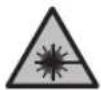
Do not point the laser beam at people or animals, and do not look into the direct or reflected laser beam. This can dazzle other people, cause accidents, or damage the eye.
If a laser beam hits the eye, close the eyes immediately and turn the head away from the laser beam.
▶ Do not make any modifications to the laser device.
- Do not use the laser glasses (accessory) as protective goggles. The laser glasses are for better visibility of the laser alignment beam; they do not protect against laser radiation.
▶ Do not use the laser glasses (accessory) as sunglasses or while driving. The laser glasses do not provide full UV protection and reduce color perception.
Only allow the measuring tool to be serviced by qualified and trained personnel and only with original spare parts. This ensures the safety of the measuring tool.
- Do not let children use the laser measuring tool without supervision. They may unintentionally dazzle other people or themselves.
- Do not work with the measuring tool in areas with explosion hazard where flammable liquids, gases, or dust are present. In the measuring tool
sparks may be produced, which can ignite dust or vapors.
▶ Do not modify or open the battery. There is a risk of short-circuit.
In case of damage and improper use of the battery, vapors may escape. The battery can catch fire or explode. Ventilate the area and seek medical attention if you experience any symptoms. The vapors may irritate the respiratory tract.
In case of improper use or a damaged battery, flammable liquid may leak from the battery. Avoid contact. In case of accidental contact, rinse with water. If the liquid comes into contact with the eyes, also consult a doctor. Liquid escaping from the battery can lead to skin irritation or burns.
Sharp objects such as nails or screwdrivers, as well as the effect of external forces, can damage the battery. They can cause an internal short-circuit and the battery may burn, emit smoke, explode, or overheat.
▶ Keep the battery that is not in use away from paper clips, coins, keys, screws, or other small metal objects that could cause a short-circuit of the contacts. A short-circuit between the battery contacts can result in burns or fire.
▶ Use the battery only in products from the manufacturer. Only then is the battery protected against dangerous overload.
Only charge batteries in chargers recommended by the manufacturer. There is a risk of fire if a charger suitable for one type of battery is used to charge other types of batteries.

Protect the battery from heat, e.g., also from continuous sunlight, fire, dirt, water, and moisture. There is a risk of explosion or short circuit.
WARNING

Keep the button cell away from children. Button cells are dangerous.
Button cells must never be swallowed or inserted into any body orifice. If you suspect that a button cell has been swallowed or inserted into any body orifice, seek medical attention immediately. Swallowing a button cell can cause severe internal chemical burns within 2 hours and can be fatal.
When replacing the button cell, make sure you do it correctly. There is a risk of explosion.
▶ Use only the button batteries mentioned in these operating instructions. Do not use other button batteries or other power sources. - Do not attempt to recharge button batteries and do not short-circuit the button battery. The button battery may leak, explode, burn, and injure people. ▶ Dispose of discharged button batteries properly. Button batteries may leak and consequently damage the product or injure people. - Do not overheat the button battery and do not throw it into fire. The button battery may leak, explode, burn, and injure people. - Do not damage the button battery and do not disassemble it. The button battery may leak, explode, burn, and injure people. - Do not let a damaged button battery come into contact with water. The lithium that escapes from the battery can form hydrogen in contact with water and cause fire, explosion, or injury to people. ▶ Do not use the measuring tool anymore if the button battery holder cannot be closed properly and completely; remove the button battery and have the measuring tool repaired. High temperature differences in a thermal image can cause even high temperatures to be displayed in a color that will be associated with low temperatures. Contact with such a surface can cause burns. Correct temperature measurements are only possible if the set emissivity and the emissivity of the object match. Objects can be displayed with a very high or very low temperature, which can cause danger in case of contact. - Do not point the measuring tool directly at the sun or at high-power CO₂ lasers. This can cause damage to the detector. ▶ Protect the measuring tool, especially the camera area and infrared lens, from moisture, snow, dust, and dirt. The receiving lens can become fogged or dirty and falsify the measurement results. Incorrect device settings and other atmospheric influencing factors can lead to incorrect measurements. Objects can be displayed with a very high or very low temperature, which can cause danger in case of contact.
Product Description and Service
Please observe the illustrations at the front of these operating instructions.
Intended Use
This thermal imaging camera is intended for non-contact temperature measurements of surfaces.
The displayed thermal image shows the temperature distribution of the field of view of the thermal imaging camera and thus allows different temperature deviations to be presented in color.
In this way, in professional applications, surfaces and objects can be analyzed without contact for temperature differences or anomalies, to make components and/or possible weak points visible, among other things:
- Thermal insulation and insulation (e.g., finding thermal bridges),
- Active heating and hot water pipes (e.g., underfloor heating) in floors and walls,
- overheated electrical components (e.g. fuses or terminals),
- defective or damaged machine parts (e.g. overheating due to a defective ball bearing).
The measuring tool is not suitable for measuring the temperature of gases.
The measuring tool must not be used for human medical purposes.
Find out about veterinary applications at www.bosch-professional.com/thermal.
The measuring tool is suitable for indoor and outdoor use.
This product is a consumer laser product in accordance with EN 50689.
The light of this measuring tool is used to illuminate the direct work area of the measuring tool for image recording purposes and serves as a permanent work light.
The laser point must not be used as a laser pointer. It is used exclusively to mark the measuring area.
Illustrated components
The numbering of the illustrated components refers to the representation of the measuring tool on the schematic page.
(1) Protective cap (2) Opening for laser beam emission (3) Visual camera (4) Work light (5) Infrared sensor (6) Pause/Start measurement button (7) Battery compartment (8) Laser warning plate (9) Button cell holder
(10) Screw for the button cell holder
(11) Cover for USB socket and button cell holder
(12) USB Type-C ®a) socket
(13) Laser key
(14) Battery/ battery adapter unlock key
(15) Battery b)
(16) USB Type-C cable ®b
(17) Multifunction key
(18) On/off/back key
(19) Display
(20) Serial number
(21) Battery adapter housing
(22) Batteries b)
(23) Battery adapter locking cover
a) USB Type-C® and USB-C® are registered trademarks of USB Implementers Forum.
b) Accessories shown or described are not included in the scope of delivery.
Indication elements
(a) Emission level indication
(b) Reflected temperature indication
(c) Average temperature indication
(d) Memory full symbol
(e) Work light symbol
(f) Laser symbol
(g) Charge level indicator
(h) Maximum surface temperature indication in the measuring range
(i) Scale
(j) Minimum surface temperature indication in the measuring range
(k) Fix temperature scale symbol
(I) Cold spot indication (example)
(m) Reticle with temperature indication
(n) Hot spot indication (example)
(o) Menu symbol
Technical data
Thermal imaging camera GTC 12V-450-13
| Número de produto | 3 601 K83 900 |
| Resolução sensor de infravermelhos 256 × 192 px | |
| Sensibilidade térmica A) | ≤ 50 mK |
| Faixa espectral 8-14 μm | |
| Campo de visão (FOV) A) | 55,6° × 42° |
| Resolução espacial (IFOV) 3,79 mrad | |
| Distância de focagem A) | ≥ 0,5 m |
| Foco fixo | |
| Taxa de atualização da imagem térmica ≤ 9 Hz | |
| Amplitude de medição da temperatura da superfície A) | -20 ... +450 °C |
| Precisão de medição temperatura da superfície A)(B)(C) | |
| >0 °C ... ≤ +100 °C D) | ±2 °C |
| >+100 °C E) | ±2% |
| Resolução da temperatura 0,1 °C | |
| Tipo de mostrador TFT | |
| Tamanho do mostrador 2,8" | |
| Resolução do mostrador 480 × 360 px | |
| Resolução da câmara visual integrada 2 MP (640 × 480 px) | |
| Formato imagem .jpg | |
| Elementos guardados por salvaguarda 1 × imagem térmica (screenshot),1 × imagem real visual incl. valores de temperatura (metadados) | |
| Número máx. de imagens na memória de imagens interna 500 | |
| Altura máx. de utilização acima da altura de referência 2000 m | |
| Grau de sujidade de acordo com a IEC 61010-1 | 2 F) |
| Humidade relativa do ar máx. A) | 90% |
| Classe de laser | 2 |
| Tipo de laser | < 1 mW, 645-660 nm |
54 | English
Thermal imaging camera GTC 12V-450-13
| Divergência do raio laser 1,5 mrad (ângulo completo) | |
| Abastecimento de energia | |
| – Bateria (iões de lítio) 12 V | |
| – Pilhas (mangano alcalino, com adaptador de pilhas) 4 × 1,5 V LR6 (AA) | |
| – Baterias (NiMH, com adaptador de pilhas) 4 × 1,2 V HR6 (AA) | |
| Tempo de autonomia G) | |
| – Bateria (iões de lítio) H)J | 8 h |
| – Pilhas (mangano alcalino) 4 h | |
| Abastecimento de energia Hora do sistema CR1225 (pilha de lítio de 3 V) | |
| Standard USB 2.0 | |
| Porta USB USB Type-C® | |
| Peso J) | 0,354 kg |
| Dimensões (comprimento × largura × altura) K) | 89 × 79 × 209 mm |
| Tipo de proteção (exceto bateria/pilhas, na posição vertical) IP54 | |
| Temperatura ambiente recomendada durante o carregamento 0 °C ... +35 °C | |
| Temperaturas ambiente permitidas | |
| – em funcionamento -10 °C ... +50 °C | |
| – no armazenamento com bateria -20 °C ... +50 °C | |
| – no armazenamento sem bateria -20 °C ... +70 °C | |
| Baterias recomendadas GBA 12V... | |
| Carregadores recomendados | GAL 12...GAX 18... |
A) according to VDI 5585 (average value)
B) With an ambient temperature of 20–23 °C and an emissivity of ≥ 0.95, measuring distance: 1 m, operating time: > 5 min, aperture of 150 mm, with work light switched off
C) Plus the application-dependent deviation (e.g. reflection, distance, ambient temperature)
D) Applies to the center point, for all other pixels additionally ±1 °C
E) Applies to the center point, for all other pixels additionally ±1%
F) Only non-conductive dirt occurs, but occasional temporary conductivity due to condensation is expected.
G) With work light switched off and average display brightness
H) depending on the battery used
I) with an ambient temperature of 20-30 °C
J) Weight without battery/battery adapter/batteries
K) With GBA 12V 2.0Ah or battery adapter
The serial number (20) on the rating plate serves for unambiguous identification of your measuring instrument.
Power supply for the measuring tool
The measuring tool can be operated with a Bosch lithium-ion battery, with conventional batteries, or with conventional NiMH batteries.
Battery operation (see figure A)
▶ Use only the chargers listed in the technical data. Only these chargers are suitable for the lithium-ion batteries used in your measuring tool.
Note: Due to international transport regulations, lithium-ion batteries are supplied partially charged.
To ensure full battery power, charge the battery completely before first use.
To insert the charged battery (15), push it into the battery compartment (7) until it audibly clicks into place.
To remove the battery (15), press the release buttons (14) and pull the battery out of the battery compartment (7). Do not use force.
Battery operation with conventional batteries (see figure B)
For operation with conventional batteries, it is recommended to use alkaline manganese batteries or NiMH batteries.
The batteries are inserted into the battery adapter.
The battery adapter is intended exclusively for use in the specified Bosch measuring tools and must not be used with power tools.
To insert the batteries, push the housing (21) of the battery adapter into the battery compartment (7). Insert the batteries according to the figure on the closing lid (23) into the housing. Slide the closing lid onto the housing until it audibly clicks into place.
To remove the batteries (22), press the release buttons (14) on the closing lid (23) and pull it off. Remove the batteries. To remove the housing (21) from the battery compartment, grasp the housing and pull it out of the measuring tool while applying slight pressure to the side wall.
Always replace all batteries or rechargeable batteries at the same time. Only use batteries or rechargeable batteries from a single manufacturer and with the same capacity.
Remove the batteries from the measuring tool if it will not be used for an extended period. Batteries may corrode if stored in the measuring tool for a long time.
Optimal handling of the battery
Protect the battery from moisture and water.
Store the battery only in the temperature range of -20 °C to 50 °C. For example, do not leave the battery in the car in summer.
A reduced operating time after charging indicates that the battery is worn out and must be replaced.
Observe the notes on environmentally friendly disposal.
Operation
Protect the measuring tool from moisture and direct sunlight. Do not expose the measuring tool to extreme temperatures or temperature fluctuations.
Do not leave it, for example, in the car for a long time. In case of larger temperature fluctuations, let the measuring tool reach ambient temperature before using it. In case of extreme temperatures or temperature fluctuations, the accuracy of the measuring tool may be impaired.
Allow the measuring tool to acclimatize properly. In case of strong temperature fluctuations, acclimatization may take up to 60 minutes.
This may be the case, for example, when you store the measuring tool in a cold car and then take a measurement in a warm building.
Avoid dropping the measuring tool or subjecting it to strong impacts.
If the measuring tool has been subjected to strong external influences or in case
of unusual occurrences during operation, have the tool checked at an authorized Bosch customer service center.
Start-up
On first use
When switching on the measuring tool for the first time or after resetting it to factory settings, some basic settings must be made. Select the desired values by pressing the multi-function button (17) up, down, left, or right. Press the multi-function button (17) in the middle to confirm the selection. Once you confirm your selection, the next setting will be displayed on the screen. The status bar at the top shows the total number and the number of remaining settings.
The following basic settings are available:
Switching on/off
To measure, open the protective cap (1). During work, ensure that the infrared sensor is not closed or covered.
To switch on the measuring tool, press the on/off button (18). A start-up sequence appears on the display (19). After the start-up sequence, the measuring tool immediately starts measuring and continues to do so until it is switched off.
Note: In the first few minutes, the measuring tool may synchronize more frequently, as the sensor and ambient temperatures have not yet synchronized. The re-synchronization of the sensor allows for precise measurement.
During this period, the temperature indication may be marked with \~. In the case of large variations in ambient temperature, this effect is intensified. Therefore, if possible, switch on the measuring tool a few minutes before starting the measurement so that it can stabilize thermally.
To switch off the measuring tool, press the on/off button (18) for more than 1 second. The measuring tool saves all settings and then switches off. Close the protective cap (1) to transport the measuring tool safely.
In the main menu, you can select whether and after what time the measuring tool switches off automatically (see "Main menu", page 58).
If the battery or the measuring tool is outside the operating temperature specified in the technical data, the measuring tool switches off automatically after a brief warning (see "Errors – Causes and solutions",
page 60). Let the measuring tool reach the normal temperature and then switch it on again.
Navigating the various menus
Navigating the various menus of the measuring tool:
- To call up the menu bars: press the multifunction key (17) in the middle or on the left. The menu bars on the right and left appear on the display, with the main menu highlighted.
- To scroll in the left menu bar/navigate in the main menu: press the multifunction key (17) up, down, left, or right.
- To switch to the left or right menu bar: press the multifunction key (17) left or right.
- To confirm the selection/switch to the submenu: press the multifunction key (17) in the middle.
- To return to a higher menu from a submenu: press the back key (18).
Measurement preparation
Setting the emissivity for surface temperature measurements
The emissivity of an object depends on the material and structure of its surface. It indicates how much infrared thermal radiation the object emits compared to an ideal thermal emitter (black body, emissivity = 1), and is therefore a value between 0 and 1.
To determine the surface temperature, the natural infrared thermal radiation emitted by the targeted object is measured without contact. For correct measurements, the emissivity set on the measuring instrument must be checked before each measurement and, if necessary, adapted to the measurement object.
The emissivities preset on the measuring instrument are reference values.
You can select one of the preset emissivities or enter an exact numerical value. Set the desired emissivity via the menu → (see "Main menu", page 58).
Correct temperature measurements are only possible if the adjusted emissivity and the emissivity of the object match.
The lower the emissivity, the greater the influence of reflected temperature on the measurement result. Therefore, when changing the emissivity, always adapt the reflected temperature. Set the reflected temperature via the menu → (see "Main menu", page 58).
Presumed temperature differences displayed by the measuring instrument may be due to different temperatures and/or different emissivities. In the case of very different emissivities, the displayed temperature differences may clearly diverge from the actual ones.
If there are several measurement objects of different materials or structures within the measurement range, the displayed temperature values are only accurate for objects that match the set emissivity. For all other objects (with different emissivities), the displayed color differences can be used as an indication of temperature relationships.
Indications on measurement conditions
Highly reflective or shiny surfaces (e.g., shiny tiles or polished metals) can significantly distort or affect the displayed results. If necessary, apply dark, matte, thermally conductive adhesive tape to the measurement area. Allow the tape to reach the surface temperature for a few moments.
For reflective surfaces, pay attention to a favorable measurement angle so that thermal radiation reflected from other objects does not distort the result. For example, in vertical measurements from the front, reflection of your own body heat can affect the measurement.
Thus, on a flat surface, the contours and temperature of your body may be displayed (reflected value), which do not correspond to the actual temperature of the measured surface (emitted value or actual surface value).
In principle, measurement through transparent materials (e.g., glass or transparent plastics) is not possible.
Measurement results are more accurate and reliable the better and more stable the measurement conditions are. Thus, not only strong temperature fluctuations in the ambient conditions are relevant, but also strong temperature fluctuations of the measured object, which can impair accuracy.
Infrared temperature measurement is impaired by smoke, steam/high humidity, or dusty air.
Indications for better measurement accuracy:
- Get as close as possible to the measurement object to minimize disturbances between you and the measurement area.
- Ventilate interior spaces before measurement, especially if the air is polluted or has a lot of steam. Let the room air out until it reaches normal temperature again.
Marking the measurement point
- Do not point the laser beam at people or animals and do not look into the laser beam, even from greater distances.
The measuring instrument is equipped with a laser to mark the measurement point.
Press and hold the laser button (13). The laser symbol (f) is displayed in the status bar and a red circle appears around the reticle (m). The overlay of the laser and the reticle is exactly opaque at a distance of 1 m. If you release the laser button (13), the laser switches off.
Assignment of temperatures based on the scale
On the right side of the display, the scale (i) is shown. The values at the upper and lower ends are based on the maximum temperature detected in the thermal image (h) or the minimum temperature (j). The scale evaluates 99.99% of the total pixels. The assignment of a color to a temperature value in the image is done with a uniform (linear) distribution.
Thus, with the help of the different shades, it is possible to assign temperatures within these two limit values. A temperature that lies exactly between the maximum and minimum values is, for example, assigned to the middle color range on the scale.
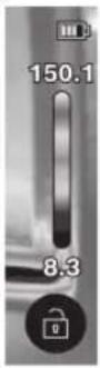
To determine the temperature of a specific area, move the measuring instrument so that the reticle with temperature indication (m) is directed at the desired point or area. In automatic mode, the color spectrum on the scale is always divided linearly (= uniformly) across the entire measurement area within the maximum or minimum temperatures.
The measuring instrument displays all measured temperatures relative to each other. If, in an area, for example in a color display, heat is shown in a bluish color scheme, this means that the bluish areas belong to the colder measurement values in the current measurement area. However, these areas may be in a temperature range that could potentially cause injury. Therefore, always pay attention to the temperatures displayed on the scale or directly in the reticle.
Functions
Observe the information on how to navigate the various menus (see "Navigating the various menus", page 56).

Illumination of the measurement object
The measuring instrument is equipped with the work light (4). It serves to illuminate the direct work area of the measuring instrument for image recording purposes and serves as a permanent work light.
To switch the work light on/off, call up the left sidebar. Go to the menu item / and confirm your selection. When the work light is on, this is displayed in the status bar.
The light switches off automatically after 2 minutes to avoid affecting measurement accuracy.
You can set the automatic switch-off time in the menu at .
Overlay of thermal and real images
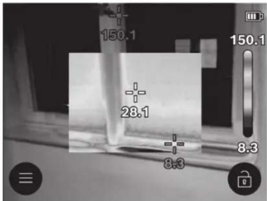
For better orientation (= spatial assignment of the displayed thermal image), a real thermal image with compensated temperature ranges can additionally be associated.
Note: The overlay of thermal and real images is exactly opaque at a distance of 1 m. In principle, if the distances are different relative to the measurement object, a deviation occurs between the thermal and real images. This displacement can be compensated with special Bosch applications. Information about the applications and their compatibilities can be found on the product page of the measuring instrument or at www.bosch-professional.com/thermal.
The measuring instrument offers the following possibilities:
- 100% infrared image
Only the thermal image is displayed.

The displayed thermal image is placed transparently over the real image. This makes it easier to detect objects.
To activate/deactivate the setting, call up the left sidebar and go to the menu item / . Confirm your selection by pressing the multifunction key (17) in the middle.
- Picture-in-picture
The displayed thermal image is reduced and the surrounding area is displayed as a real image. This setting improves the local assignment of the measurement range.
To activate/deactivate the setting, call up the left sidebar and go to the menu item / . Confirm your selection by pressing the multifunction key (17) in the middle.
Adapting the color reproduction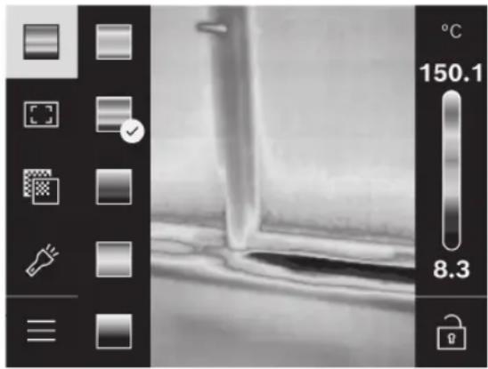
Depending on the measurement situations, different color schemes can facilitate the analysis of the thermal image and better reproduce objects or situations on the display. The measured temperatures are not influenced by this. Only the representation of the temperature values is changed.
To change the color scheme, call up the sidebar and go to the menu item "Color scheme". Confirm your selection by pressing the multifunction key (17) in the middle.
Fixing the scale
The adaptation of the color distribution in the thermal image is done automatically, however, it can be fixed by pressing the right multifunction key (17) and then the middle one. This allows the comparability of thermal images that were captured under different thermal conditions (e.g. when checking several rooms for thermal bridges) or also the hiding of an extremely cold or hot object in the thermal image, which would otherwise be distorted (e.g. radiator as a hot object in the search for thermal bridges).
To switch the scale back to automatic, call up the right sidebar and press the multifunction key (17) in the middle. Now the temperatures behave dynamically and adapt to the measured minimum and maximum values.
Main menu
Call up the left sidebar (see "Navigating the various menus", Page 56). To access the main menu, press the multifunction key (17) in the middle.
- This menu item can delete the saved images individually or all at once.
• (a)
For some of the most common materials, saved emission degrees are available. To make searching easier, the values are summarized in groups in the catalog of emission degrees. In the menu item, first select the
appropriate category and then the appropriate material. If you know the exact emission degree of your measuring object, you can also set it as a numerical value in the menu item .
- (b)
Adjusting this parameter can improve the measurement result, especially on materials with a low emission degree (= high reflection). In some situations (especially indoors), the reflected temperature corresponds to the ambient temperature. If objects with strong temperature deviations are near strongly reflective objects that can influence the measurement, you should adapt this value. To do this, press the left or right multifunction key (17).
-
To ensure high accuracy over the entire measurement area, the measurement is carried out in 2 temperature ranges. In the measurement function , the measuring instrument automatically selects the appropriate temperature range based on the temperature distribution in the thermal image. It evaluates how many measurement values are above a certain temperature limit. If you are measuring very small but hot objects, this can lead to the selection of the low temperature range, which is unsuitable for high temperatures. This is visible in the symbol \~ before the temperature indication. In that case, switch to the measurement function <100 °C ... 450 °C> or <-20 °C ... 100 °C>, where the color distribution corresponds to the adjusted temperature range. The setting is indicated on the scale with an up or down arrow.
-
• (m): /
The point is displayed in the center of the thermal image and indicates the temperature value measured at this location.
• (n): /
The hottest point (= measuring pixel) is marked in the thermal image with a red reticle. This makes it easier to find critical points (e.g., loose contact terminals in the distribution cabinet).
- (I): /
The coldest point (= measuring pixel) is marked in the thermal image with a blue reticle. This makes it easier to find critical points (e.g., leak point in the window).
The average temperature (c) is displayed at the top left of the thermal image (average temperature of all measured values in the thermal image). This can facilitate the determination of the reflected temperature.
In this menu item you can adjust the brightness of the display illumination.
In this menu item you can select the time interval for the automatic shutdown of the work light when no key is pressed.
In this menu item you can select the time interval after which the measuring instrument should automatically shut down when no key is pressed. You can also deactivate the automatic shutdown by selecting the setting .
In this menu item you can also, in addition to setting the time and date, change the respective formats.
In this menu item you can select the language used for the display.
This menu item can reset the measuring tool to factory settings and permanently delete all data. This may take a few minutes. Then press the right multifunction button (17) to delete all files, or the left multifunction button (17) to cancel the process.
-
In this menu item you can access information about the measuring tool. Here you will find the serial number of the measuring tool and the installed software version. You can also find more information about the measuring tool and software updates.
To exit any menu and return to the standard display screen, you can also press the Measurement button (6).
Software update for the measuring tool
If necessary, you can update the measuring tool via the USB Type-C® interface. For more information, see:
www.bosch-professional.com/thermal-update.
Documentation of measurement results
Saving measurement results
Immediately after switching on, the measuring tool starts measuring and continues to do so until it is switched off. To save an image, point the camera at the desired measurement object and press the measurement button (6). The image is saved in the internal memory of the measuring tool. The measurement is frozen and displayed on the screen. This allows a detailed analysis of the image and subsequent adjustment (e.g., the color scheme). If you do not wish to save the frozen image, start the measurement mode again with the measurement button (6). If you wish to save the image in the internal memory of the measuring tool, press the middle multifunction button (17).
Accessing saved images
To access saved thermal images, proceed as follows:
- Immediately after saving, press the middle multifunction button (17) again. The preview of the last saved photo appears on the screen.
- Alternatively, you can call up the saved photos in the menu item.
- To switch between the saved thermal images, press the right or left multifunction button (17).
In addition to the thermal image, the visual image was also saved. To access it, press the multifunction button (17) up or down.
After 5 s, the measuring tool switches to the full image view. In the full image view, the title bar indication is hidden so that you can see all details of the thermal image.
By pressing the multifunction button (17) up or down, you can switch between views.
Deleting saved images
To delete one or all thermal images, press the multifunction button (17) in the middle. A submenu opens.
- Here you can select whether you want to delete only this image or all images. Confirm the selection with the multifunction button (17) in the middle.
In the selection, you can choose between and . Confirm the selection with the multifunction button (17) in the middle.
- In this submenu, you can also view information regarding the emissivity and reflected temperature.
The data fragments of the images remain in the memory and can be reconstructed. For permanent deletion, select in the main menu → .
Data transfer
Data transfer via USB port
Open the cover (11) of the USB Type-C® socket. Connect the USB Type-C® socket (12) of the measuring tool to your computer using the supplied USB Type-C® cable (16).
Now switch on the measuring tool with the on/off button (18).
Open the file browser on your computer and select the drive GTC_450. The saved files can be copied from the internal memory of the measuring tool, moved on your computer, or deleted.
Once you have completed the desired process, disconnect the drive from the computer in the usual way and then switch off the measuring tool again with the on/off button (18).
Attention: always disconnect the drive of your operating system first (eject drive), otherwise the internal memory of the measuring instrument may be damaged.
60 | Portuguese
Remove the USB Type-C® cable and close the cover (11). Keep the USB port cover always closed to prevent dust or water splashes from entering the housing.
Note: connect the measuring instrument via USB exclusively to a computer. The measuring instrument may be damaged if connected to other devices.
Note: the USB Type-C® interface is exclusively for data transfer. Batteries and rechargeable batteries cannot be charged through it.
Post-processing of thermal images
You can edit saved thermal images later with special Bosch applications. Information about the applications and their compatibility can be found on the product page of the measuring instrument or at www.bosch-professional.com/thermal.
Errors - Causes and solutions
In the event of a failure, the measuring instrument performs a restart and can then be used again. Otherwise, the overview below can help you with persistent error messages.
Error Cause Solution
| Não é possível ligar o instrumento de medição. | Bateria/pilhas vazias Carregue a bateria ou troque as pilhas. | |
 | Erro de bateria/pilhas Troque a bateria ou as pilhas. | |
 | Bateria/pilhas demasiado quentes ou demasiado frias | Deixe a bateria atingir a temperatura normal ou troque a bateria ou as pilhas. |
 | Instrumento de medição demasiado quente ou demasiado frio | Deixe o instrumento de medição atingir a temperatura normal. |
 | Ligação USB ou cabo USB com defeito | Verifique se é possível ligar o instrumento de medição a um outro computador. Se não for possível, envie o instrumento de medição para um posto de assistência técnica autorizado da Bosch.Nota:use sempre o cabo USB fornecido. |
| Não é possível ligar o instrumento de medição a um computador. | ||
 | Pilha botão vazia | Troque a pilha botão (ver "Trocar a pilha botão (ver figura C)", Página 61). Confirme a sua troca com "OK" premindo a tecla multifunções (17) no meio. |
| Explicação dos termosPara mais informações consulte www.bosch-professional.com/thermal.Radiação térmica infravermelhaA radiação térmica infravermelha é uma radiação eletromagnética emitida por qualquer corpo acima de O Kelvin (-273 °C). A quantidade de radiação depende da temperatura e do grau de emissão do corpo.Grau de emissãoO grau de emissão de um objeto depende do material e da estrutura da sua superfície. Este indica quanta radiação térmica infravermelha o objeto emite comparativamente a um emissor térmico ideal (corpo preto, grau de emissão ε = 1) sendo consequentemente um valor entre 0 e 1. | Ponte térmicaComo ponte térmica é designado um local na parede exterior de um edifício no qual ocorre uma elevada perda térmica local devido à construção.As pontes térmicas podem originar um elevado risco de formação de dolor.Temperatura refletida/refletividade de um objetoA temperatura refletida são as radiações térmicas que não são emitidas pelo próprio objeto. Dependendo da estrutura e do material, as radiações ambiente refletem-se no objeto a medir e falsificam assim o verdadeiro resultado da temperatura.Distância do objetoA distância entre o objeto de medição e o instrumento de medição influencia o tamanho da área captada por píxel. | |
Explanation of terms
Infrared thermal radiation
Emissivity
Thermal bridge
Reflected temperature/reflectivity of an object
Object distance
With a greater object distance, you can capture increasingly larger objects.
| Distância (m) Tamanho do píxel infravermelho (mm) | Largura × altura área infravermelha (m) |
| 0,30 1,14 ~ 0,29 × 0,22 | |
| 0,55 2,08 ~ 0,53 × 0,40 | |
| 1,00 3,79 ~ 0,97 × 0,73 | |
| 2,00 7,58 ~ 1,94 × 1,46 | |
| 5,00 18,95 ~ 4,85 × 3,64 |
Maintenance and service
Maintenance and cleaning
Store and transport the measuring tool only in a suitable container, such as the original packaging.
Always keep the measuring tool clean. A dirty infrared sensor (5) can impair measurement accuracy.
No liquid must penetrate the measuring tool during cleaning.
Do not attempt to remove dirt from the infrared sensor (5), the camera (3), the work light (4), or the laser beam outlet opening (2). Do not wipe the infrared sensor and camera with a cloth (risk of scratches).
Clean the areas around the laser outlet opening regularly and ensure there are no lint residues.
If you wish to have your measuring tool recalibrated, contact an authorized Bosch service center.
Send the measuring tool for repair in its original packaging.
There are no user-serviceable parts inside the measuring tool. Opening the housing can destroy the measuring tool.
Replacing the button battery (see figure C)
Open the cover (11).
Loosen the screw (10) on the button battery holder. Remove the button battery holder (9) from the measuring tool.
Replace the button battery. Tighten the screw (10) again after placing the button battery holder.
After-sales service and advice
The after-sales service answers your questions regarding repair and maintenance of your product, as well as spare parts. Exploded views and information on spare parts can be found
at: www.bosch-pt.com
Our Bosch consultant team will be happy to answer any questions you have about our products and accessories.
For all questions and spare parts orders, please quote the 10-digit reference number from the product nameplate.
Brazil
Robert Bosch Ltda. – Divisão de Ferramentas Elétricas Rodovia Anhanguera, Km 98 - Parque Via Norte 13065-900, CP 1195
Campinas, São Paulo
Tel.: 0800 7045 446
www.bosch.com.br/contato
Portugal
Robert Bosch LDA
Avenida Infante D. Henrique
Lotes 2E - 3E
1800 Lisboa
To place your online order for parts, visit www.ferramentasbosch.com.
Tel.: 21 8500000
Fax: 21 8511096
Other service addresses can be found at:
www.bosch-pt.com/serviceaddresses
Transport
The recommended lithium-ion batteries are subject to hazardous materials laws. The batteries can be transported on the road by the user without further obligations.
In the case of shipment by third parties (e.g., air transport or forwarding), special requirements regarding packaging and labeling must be observed. In this case, it is
necessary to consult a hazardous materials specialist when preparing the part to be worked on.
Batteries should only be transported if the housing is in perfect condition. Tape over open contacts and pack the battery so that it cannot move around inside the packaging. Also observe any other national regulations that may exist.
Disposal

Measuring instruments, batteries/rechargeable batteries, accessories, and packaging should be sent for environmentally friendly recycling of raw materials.

Do not dispose of the measuring instrument and batteries/rechargeable batteries in household waste!!
Only for EU countries:
Measuring tools that are no longer useful and defective or used batteries must be disposed of separately. Use the collection systems provided for this purpose.
If disposed of improperly, waste electrical and electronic equipment can have adverse effects
62 | Italian
on the environment and human health due to the possible presence of hazardous substances.
Batteries:
Lithium-ion batteries:
Observe the instructions in the Transport section (see "Transport", page 61).
Italian
Safety Instructions

Read and observe all warnings and instructions to work with the measuring tool safely and without danger. If the measuring tool is not used in accordance with these instructions, the protective devices integrated in the tool may be impaired. Never make the warning labels on the measuring tool illegible. KEEP THESE INSTRUCTIONS SAFE AND HAND THEM OVER TOGETHER WITH THE MEASURING TOOL IF YOU PASS IT ON TO A THIRD PARTY.
Caution – If operating or adjustment devices other than those specified here are used or if other procedures are carried out, there is a possibility of hazardous radiation exposure. ▶ The measuring tool is supplied with a laser warning label (marked in the figure showing the measuring tool). If the text on the laser hazard label is in a foreign language, affix the supplied label with the text in your language before initial operation.
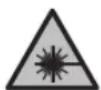
Never point the laser beam at people or animals, and do not look into the laser beam, either directly or reflected. The laser beam can dazzle people, cause accidents, or damage eyes.
If a laser beam hits an eye, close your eyes immediately and turn your head away from the beam.
▶ Do not make any modifications to the laser device.
▶ Do not use the laser goggles (accessory) as protective goggles. Laser goggles make the laser beam more visible, but they do not protect against laser radiation.
Do not use the laser goggles (accessory) as sunglasses or in road traffic. Laser goggles do not provide full UV protection and reduce color perception.
Have the measuring tool serviced only by qualified technical personnel and only using
original spare parts. This ensures the safety of the measuring tool.
Do not allow children to use the laser measuring tool without proper supervision. They could inadvertently dazzle other people or themselves.
Do not work with the measuring tool in explosive atmospheres where flammable liquids, gases, or dusts are present. Sparks may be produced in the measuring tool that can ignite dust or vapors.
Do not modify or open the battery. There is a risk of short circuit.
If the battery is damaged or used improperly, vapors may escape. The battery can catch fire or explode. Provide fresh air and seek medical attention if you feel unwell. Vapors can irritate the respiratory tract.
In case of incorrect use or a damaged battery, flammable liquid may escape from the battery. Avoid contact with the liquid. In case of accidental contact, rinse thoroughly with water. Seek medical attention immediately if the liquid gets into your eyes. Liquid escaping from the battery may cause skin irritation or burns.
If sharp objects, such as nails or screwdrivers, are used, or if external force is applied, the battery may be damaged. An internal short circuit may occur, and the battery may catch fire, emit smoke, explode, or overheat.
Do not bring unused batteries near paper clips, coins, keys, nails, screws, or other small metal objects that could bridge the contacts. A short circuit between battery contacts could cause burns or fires.
Use the battery only with products from the manufacturer. Only in this way will the battery be protected from dangerous overloads.
Charge batteries only with chargers recommended by the manufacturer. If a charger suitable for a certain type of battery is used with different batteries, there is a risk of fire.

Protect the battery from heat, for example from continuous solar radiation, fire, dirt, water, and moisture. There is a risk of explosion and short circuit.




WARNING
Ensure that the button cell battery is kept out of the reach of children. Button cell batteries are dangerous.
Button batteries must not be swallowed or inserted into other body cavities. If you suspect that a button battery has been swallowed or inserted into another body cavity, contact a doctor immediately.
Swallowing a button battery can cause severe internal injuries within 2 hours, with potentially fatal consequences.
When replacing the button battery, ensure it is replaced correctly. There is a risk of explosion. - Use only the button batteries specified in these instructions for use. Do not use other types of button batteries or other power sources. Do not attempt to recharge the button battery or short-circuit it. The button battery may leak, explode, catch fire, and cause injury. Remove and dispose of depleted button batteries in accordance with local regulations. Depleted button batteries may leak and consequently damage the product or cause injury. ▶ Do not overheat the button battery or throw it into fire. The button battery may leak, explode, catch fire, and cause injury. ▶ Do not damage or disassemble the button battery. The button battery may leak, explode, catch fire, and cause injury. ▶ Do not bring a damaged button battery into contact with water. When in contact with water, the lithium that escapes from the battery can generate hydrogen and cause a fire or explosion, or cause injury. Do not continue to use the measuring tool if the button battery compartment can no longer be closed properly and completely; remove the button battery and have the measuring tool repaired. In the case of large temperature differences within a thermal image, temperatures may also be represented in a color associated with low temperatures. In such a case, contact with the surface can cause burns. Correct temperature measurements can only be performed if the set emissivity and the emissivity of the object match. Objects may be displayed with a temperature that is too high or too low, which could cause a hazard in case of contact with the surface in question. ▶ Do not point the measuring tool directly at the sun or at high-power CO2 lasers. This could damage the detector. ▶ Protect the measuring tool from moisture, snow, dust, and dirt, especially the areas of the camera and the infrared lens. The receiving lens may become fogged or contaminated, falsifying measurement results. Incorrect settings of the tool and other atmospheric influencing factors can lead to incorrect measurements. Some objects may be displayed with a temperature that is too high or too low, which could cause a hazard in case of contact with them.
When replacing the button battery, be sure to replace it correctly. There is a risk of explosion. - Use only the button batteries specified in these operating instructions. Do not use other types of button batteries or other power sources. Do not attempt to recharge the button battery or short-circuit it. The button battery may leak, explode, catch fire, and cause injury. Remove and dispose of depleted button batteries in accordance with local regulations. Depleted button batteries may leak and, as a result, damage the product or cause injury. ▶ Do not overheat the button battery or throw it into a fire. The button battery may leak, explode, catch fire, and cause injury. ▶ Do not damage or disassemble the button battery. The button battery may leak, explode, catch fire, and cause injury. ▶ Do not bring a damaged button battery into contact with water. When in contact with water, the lithium that escapes from the battery can generate hydrogen and cause a fire or explosion, or cause injury. Do not use the measuring tool anymore if the button battery compartment can no longer be closed properly and completely; remove the button battery and have the measuring tool repaired. In the case of large temperature differences within a thermal image, even high temperatures could be displayed in a color associated with low temperatures. In such a case, contact with the surface can cause burns. Correct temperature measurements can only be performed if the set emissivity and the emissivity of the object match. Objects could be displayed with a temperature that is too high or too low, which could pose a danger in case of contact with the surface in question. ▶ Do not point the measuring tool directly at the sun or at high-power CO2 lasers. This could cause damage to the detector. ▶ Protect the measuring tool from moisture, snow, dust, and dirt, especially the areas of the camera and the infrared lens. The receiving lens could become fogged or contaminated, falsifying the measurement results. Incorrect settings of the tool and other atmospheric influencing factors can lead to incorrect measurements. Some objects could be displayed with a temperature that is too high or too low, which could pose a danger in case of contact with them.
Product description and services provided
Observe the figures in the front part of the operating instructions.
Intended use
This thermal camera is designed for non-contact measurement of surface temperatures.
The displayed thermal image shows the temperature distribution in the field of view of the thermal camera, allowing temperature differences to be represented in different colors.
With proper use, it is therefore possible to examine surfaces and objects without contact to detect temperature differences or thermal anomalies, to make components and/or potential problem areas visible, for example:
- thermal insulation and other insulation (e.g., detection of thermal bridges),
- active heating water pipes or hot water pipes (e.g., surface heating) inside floors or walls,
- overheated electrical components (e.g., fuses or terminals),
- defective or damaged machine components (e.g., overheating caused by defective ball bearings). The measuring tool is not suitable for measuring gas temperatures.
The measuring tool must not be used for medical purposes on people.
For use in veterinary applications, refer to www.bosch-professional.com/thermal.
The measuring tool is suitable for indoor and outdoor use.
This is a consumer laser product compliant with EN 50689.
The light of this measuring tool is designed to directly illuminate the work area of the measuring tool to enable image capture if necessary, and not to function as a permanent work light.
The laser point cannot be used as a laser pointer. It is designed exclusively for marking the measurement surface.
Illustrated components
The numbering of the components refers to the illustration of the measuring tool on the page with the graphic representation.
(1) Protective cover (2) Laser beam exit opening (3) Camera (4) Work light (5) Infrared sensor (6) Pause/Start measurement button
64 | English
(7) Battery compartment
(8) Laser beam hazard label
(9) Button cell holder
(10) Button cell holder screw
(11) Cover for USB port and button cell holder
(12) USB Type-C ®a) port
(13) Laser button
(14) Battery/adapter release button
(15) Battery b)
(16) USB Type-C ®b) cable
(17) Multifunction button
(18) Power on/off/Back button
(19) Display
(20) Serial number
(21) Battery adapter cover
(22) Batteries b)
(23) Battery adapter closing cap
a) USB Type-C® and USB-C® are registered trademarks of USB Implementers Forum.
b) The accessory illustrated or described is not included in the standard delivery.
Display elements
(a) Emission level indication
(b) Reflected temperature indication
(c) Average temperature indication
(d) Memory full symbol
(e) Work light symbol
(f) Laser symbol
(g) Charge level indicator
(h) Maximum surface temperature indication in the measuring range
(i) Scale
(j) Minimum surface temperature indication in the measuring range
(k) Fixed temperature scale symbol
(I) Cold spot indication (example)
(m) Reticle with temperature indication
(n) Hot spot indication (example)
(o) Menu symbol
Technical data
| Termocamera GTC 12V-450-13 | |
| Codice prodotto | 3 601 K83 900 |
| Risoluzione sensore a infrarossi 256 × 192 px | |
| Sensibilità termica A) | ≤ 50 mK |
| Campo spettrale 8–14 μm | |
| Campo visivo (FOV) A) | 55,6° × 42° |
| Risoluzione spaziale (IFOV) 3,79 mrad | |
| Distanza focale A) | ≥ 0,5 m |
| Fuoco fisso | |
| Frequenza di refresh immagine termica ≤ 9 Hz | |
| Campo di misurazione temperatura superficiale A) | -20 ... +450 °C |
| Precisione di misura temperatura superficiale A)B)C) | |
| >0 °C ... ≤ +100 °C D) | ±2 °C |
| >+100 °C E) | ±2% |
| Risoluzione di temperatura 0,1 °C | |
| Tipo di display TFT | |
| Dimensioni del display 2,8" | |
| Risoluzione display 480 × 360 px | |
| Risoluzione videocamera integrata 2 MP (640 × 480 px) | |
| Formato immagine .jpg | |
| Elementi memorizzati per ciascun salvataggio 1 × immagine termica (screenshot),1 × immagine visiva reale incl. valori termici (metadati) | |
| Numero immagini max. nella memoria immagini interna 500 | |
| Altitudine d'impiego max. sul livello del mare 2000 m | |
English | 65
Thermal camera GTC 12V-450-13
| Grado di contaminazione secondo IEC 61010-1 2 | F) |
| Umidità dell'aria relativa max. A) | 90% |
| Classe laser 2 | |
| Tipo di laser < 1 mW, 645–660 nm | |
| Divergenza del raggio laser 1,5 mrad (angolo giro) | |
| Alimentazione | |
| – Batteria (al litio) 12 V | |
| – Pile (alcaline al manganese con adattatore per pile) 4 × 1,5 V LR6 (AA) | |
| – Batterie (NiMH con adattatore batteria) 4 × 1,2 V HR6 (AA) | |
| Durata della carica G) | |
| – Batteria (al litio) H) I) | 8 h |
| – Pile (alcaline al manganese) 4 h | |
| Alimentazione ora di sistema CR1225 (batteria al litio da 3 V) | |
| Standard USB 2.0 | |
| Interfaccia USB USB Type-C® | |
| Peso J) | 0,354 kg |
| Dimensioni (lunghezza × larghezza × altezza) K) | 89 × 79 × 209 mm |
| Grado di protezione (eccetto pile a batteria, in posizione verti-cale) | IP54 |
| Temperatura ambiente consigliata in fase di ricarica 0 °C ... +35 °C | |
| Temperature ambiente consentite | |
| – durante il funzionamento –10 °C ... +50 °C | |
| – in caso di magazzinaggio con batteria –20 °C ... +50 °C | |
| – in caso di magazzinaggio senza batteria | -20 °C ... +70 °C |
| Batterie consigliate | GBA 12V... |
| Caricabatteria consigliati | GAL 12...GAX 18... |
A) According to VDI 5585 standard (average value)
B) At an ambient temperature of 20–23 °C and with an emissivity of ≥ 0.95, measuring distance: 1 m, operating time: > 5 min, opening of 150 mm, with work light off and laser
C) Possible deviations depending on the type of use (e.g., reflection, distance, ambient temperature)
D) Applies to the center point; for all other pixels, add ±1 °C
E) Applies to the center point; for all other pixels, add ±1%
F) Presence exclusively of non-conductive contaminants, which, however, in some cases may become temporarily conductive due to condensation.
G) With work light off and average display brightness
H) Depending on the rechargeable battery used
I) With an ambient temperature of 20-30 °C
J) Weight without battery/battery adapter/batteries
K) With GBA 12V 2.0Ah or battery adapter
For unambiguous identification of the measuring tool, refer to the serial number (20) on the rating plate.
Power supply for the measuring tool
The measuring tool can be powered either by a Bosch lithium-ion battery or by standard batteries or standard NiMH batteries.
Operation with battery (see figure A)
▶ Use only the chargers listed in the technical data. Only these chargers are suitable for the lithium-ion batteries used in your measuring tool.
Warning: Due to international transport regulations, the lithium-ion batteries are supplied partially charged.
66 | Italian
To ensure full battery power, charge it completely before initial use.
To insert the charged battery (15), push it into the battery compartment (7) until it audibly clicks into place.
To remove the battery (15), press the release buttons (14) and pull the battery out of the compartment (7). Do not use force during this operation.
Operation with batteries (see figure B)
For operation of the measuring tool, it is recommended to use alkaline manganese batteries or Ni-MH rechargeable batteries.
The batteries must be inserted into the appropriate adapter.
The battery adapter is intended solely for use in the specified Bosch measuring tools and must not be used with power tools.
To insert the batteries, push the sleeve (21) of the battery adapter into the battery compartment (7). Insert the batteries into the sleeve as shown in the image on the closing cap (23). Push the closing cap onto the sleeve until it audibly clicks into place.
To remove the batteries (22), press the release buttons (14) on the closing cap (23) and pull off the cap. Remove the batteries. To remove the inner sleeve (21) from the battery compartment, grasp the sleeve and pull it out of the measuring tool, applying slight pressure to the side wall.
Always replace all batteries or all rechargeable batteries at the same time. Use only batteries or rechargeable batteries from the same manufacturer and with the same capacity.
If the measuring tool is not used for extended periods, remove the batteries or rechargeable batteries from the tool. If left in the measuring tool for a long time, the batteries and rechargeable batteries may corrode.
Notes for optimal battery use
Protect the rechargeable battery from moisture and water.
Store the battery only in the temperature range between -20 °C and 50 °C. Do not leave the battery in the car, e.g., in summer.
A noticeable reduction in operating time after recharging indicates that the rechargeable battery needs to be replaced.
Follow the disposal instructions.
Use
▶ Protect the measuring tool from liquids and direct sunlight. Do not expose the measuring tool to extreme temperatures or temperature fluctuations. For example, avoid leaving it in a car for a long time. In case of large temperature fluctuations, allow the measuring tool to reach normal temperature before putting it into operation.
Extreme temperatures or temperature fluctuations can affect the accuracy of the measuring tool.
Make sure to let the measuring tool acclimatize properly. In case of significant temperature variations, the acclimatization time can take up to 60 minutes. This can happen, for example, when the measuring tool is stored cold in a vehicle and then a measurement is taken in a warm building. Avoid hitting or dropping the measuring tool. After strong external influences or obvious malfunctions, the measuring tool must be checked by an authorized Bosch service center.
Operation
Initial startup
When turning on the measuring tool for the first time or after resetting to factory settings, some basic settings must be made. Select the desired values by pressing the multifunction button (17) down, up, left, or right. Press the multifunction button (17) in the center to confirm the selection. Once the selection is confirmed, the next setting will be displayed on the screen. The total number and the number of remaining settings will be displayed in the status bar at the top.
The following basic settings are available:
Switching on/off
To take a measurement, open the protective cap (1). During work, make sure that the infrared sensor is not closed or covered.
To turn on the measuring tool, press the on/off button (18). A start-up sequence will be displayed on the screen (19). After the start-up sequence, the tool will immediately start measuring and continue continuously until it is turned off.
Note: In the first few minutes, the measuring tool may calibrate itself more frequently, as the sensor temperature and the ambient temperature have not yet aligned. The new sensor calibration enables precise measurement.
During this period of time, the temperature indication may be marked with \~. In the event of strong fluctuations in the ambient temperature, this effect will be more noticeable. Therefore, wherever possible, the measuring tool should be switched on a few minutes before the start of the measurement so that it can stabilize thermally.
To switch off the measuring tool, press the on/off button (18) for > 1 s. The measuring tool will save all settings and then switch off.
To transport the measuring tool safely, close the protective cap (1).
In the main menu, you can choose whether and after how long the measuring tool should switch off automatically (see "Main menu", Page 69).
If the battery or the measuring tool is outside the operating temperature specified in the technical data, the measuring tool will switch off automatically after a brief warning signal (see "Errors – Causes and remedies", Page 71). Allow the measuring tool to reach normal temperature, then switch it on again.
Navigating the menus
Navigating the different menus of the measuring tool:
- To call up the menu bars: press the multifunction button (17) in the center or to the left. The menu bars on the right and left appear on the display, while the main menu is highlighted.
- To scroll through the left menu bar/navigate in the main menu: press the multifunction button (17) up, down, left, or right.
- To switch from the left menu bar to the right one or vice versa: press the multifunction button (17) left or right.
- To confirm the selection/switch to the submenu: press the multifunction button (17) in the center.
- To return from a submenu to a higher-level menu: press the Back button (18).
Preparations for measurement
Setting the emission level for surface temperature measurements
The emission level of an object depends on the material and structure of its surface. It indicates the amount of infrared thermal radiation emitted by the object compared to an ideal thermal radiator (black body, emission level ε = 1) and is therefore a value between 0 and 1.
To determine the surface temperature, the natural infrared thermal radiation emitted by the target object is measured without contact. For correct measurements, the emissivity setting on the measuring instrument must be verified before each measurement and, if necessary, adjusted to the object being measured.
The emissivity values preset in the measuring instrument serve as reference values.
You can select one of the preset emissivity values or enter a specific value. Set the desired emissivity via the menu → (see "Main menu", page 69).
Temperature measurements can only be performed correctly if the set emissivity matches that of the object.
The lower the emissivity, the greater the influence of reflected temperature on the measurement result. Therefore, whenever the emissivity changes, the reflected temperature must also be adjusted. Set the reflected temperature via the menu → (see "Main menu", page 69).
Apparent temperature differences displayed by the measuring instrument may be due to different temperatures and/or different emissivities. If the emissivities differ greatly, the displayed temperature differences may be very different from the actual ones.
If there are multiple objects to be measured in the measuring field, made of various materials or with different structures, the displayed temperature values will be accurate only for objects compatible with the set emissivity. For all other objects (with different emissivities), the displayed color differences can be used as indications of thermal relationships.
Notes on measurement conditions
Highly reflective or glossy surfaces (e.g., glossy tiles or uncoated metal surfaces) can significantly distort or even impair the displayed result. If necessary, apply a dark, matte adhesive tape with good thermal conductivity to the measurement surface. Allow the tape to briefly adapt to the surface temperature.
For reflective surfaces, choose a favorable measurement angle so that reflected thermal radiation from other objects does not distort the measurement result. For example, when measuring vertically from the front, the reflection of your own body heat may impair the measurement. On a flat surface, the contours and temperature of your own body (reflected value) may be displayed, which do not correspond to the actual temperature of the measured surface (emitted value, or actual surface value).
Due to the operating principle, measurement through transparent materials (e.g., glass or transparent plastics) is not possible.
Measurement results will be more accurate and reliable the better and more stable the measurement conditions are. In this case, not only strong thermal fluctuations in the ambient conditions are relevant, but also strong fluctuations in the temperature of the measured object can impair accuracy.
Infrared temperature measurement is impaired by smoke, steam/high atmospheric humidity, or dusty air.
Warnings for greater measurement accuracy:
- Get as close as possible to the object to be measured to minimize any interfering factors between you and the measurement surface.
- Before taking the measurement, ventilate indoor environments, especially if the air is contaminated or has a high presence of steam. After ventilation, allow the room to adapt until the usual temperature is reached again.
Marking the measurement point
▶ Never point the laser beam at people or animals and never look in the direction of the laser beam itself, even from a great distance.
The measuring tool is equipped with a laser to mark the measurement point.
Press and hold the Laser button (13). The laser symbol (f) will be displayed in the status bar and a red circle will appear around the reticle (m). The overlap between the laser and the reticle covers exactly a distance of 1 m. When you release the Laser button (13), the laser turns off.
Temperature assignment based on the room
The scale (i) will be displayed on the right side of the display. The values at the upper and lower ends will be based on the maximum (h) or minimum (j) temperature detected in the thermal image. For the scale, 99.99% of the total pixels will be evaluated. A specific color will be assigned to a temperature value in the image in a uniformly distributed (linear) manner.
Through the various color shades, this will allow temperatures to be assigned within these two limit values. For example, if a given temperature lies exactly between the minimum and maximum values, the intermediate color range will be assigned to the scale.
To determine the temperature of a specific area, move the measuring tool so that the temperature indication reticle (m) is aimed at the desired point or area. In automatic mode, the color spectrum of the scale is always distributed linearly (i.e., uniformly) over the entire measuring range, within the maximum or minimum temperature. The measuring tool will display all measured temperatures in the measuring range in relation to each other. If, within an area, for example in a color representation, heat is displayed in the color palette with a bluish color, this indicates that the bluish areas belong to the lowest measured temperatures in the current measuring range. However, such areas may be in a temperature range that could, in some cases, cause injury. Therefore, always pay attention to the temperatures displayed on the scale or directly on the reticle.
Functions
Pay attention to the information for navigating the different menus (see "Navigating the menus", page 67).

Illumination of the measuring object
The measuring tool is equipped with a work light (4). The work light is designed to directly illuminate the work area of the measuring tool to allow for image capture, and not to function as a permanent work light.
To turn the work light on/off, call up the left sidebar. Scroll to the menu item / and confirm the selection. When the work light is on, it will be displayed in the status bar.
The light will be deactivated automatically after 2 minutes to avoid affecting measurement accuracy.
The time for automatic deactivation can be set in the menu under the item .
Overlay of thermal and real image
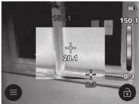
For better orientation (= assignment of the displayed thermal image), if the temperature ranges are offset, a real visual image can also be inserted.
Note: The overlay between real and thermal image has a coverage of exactly 1 m. Due to the operating principle, at distances different from the object to be measured, there will be an offset between the real and thermal image. This offset can be compensated with appropriate Bosch applications. For information on applications and their compatibility, refer to the product page of the measuring tool or visit www.bosch-professional.com/thermal.
The measuring tool offers the following options:
- 100% infrared image
Only the thermal image will be displayed.

Transparency
The displayed thermal image will be overlaid transparently on the real image. This will enable better detection of objects.
To activate/deactivate this setting, call up the left sidebar and scroll to the menu item / . Confirm the selection by pressing the multifunction key (17) in the center.

Picture-in-picture
The displayed thermal image will be cropped and the surrounding area will be displayed as a real image. This
setting improves spatial assignment of the measurement field.
To activate/deactivate this setting, call up the left sidebar and scroll to the menu item / . Confirm the selection by pressing the multifunction key (17) in the center.
Adjusting the color representation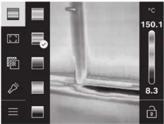
In certain measurement situations, using different color palettes can facilitate the analysis of the thermal image and allow certain objects or conditions to be better represented on the display. This does not affect the measured temperatures: only the representation of the temperature values changes.
To change the color range, call up the sidebar and scroll to the menu item "Color range". Confirm the selection by pressing the multifunction key (17) in the center.
Fixed scale
The distribution of colors in the thermal image is adjusted automatically, but it can be fixed by pressing the multifunction key (17) to the right and then in the center. This will allow comparison of thermal images acquired under different temperature conditions (e.g., when checking for thermal bridges in multiple rooms), or to hide an extremely cold or extremely hot object within the thermal image that would otherwise distort it (e.g., a radiant body indicated as a high-temperature object when searching for thermal bridges).
To return the scale to automatic, call up the right sidebar and press the multifunction key (17) in the center. The temperatures will then behave dynamically again, adapting to the measured minimum and maximum values.
Main menu
Call up the left sidebar (see "Navigation in the different menus", Page 67). To switch to the main menu, press the multifunction key (17) in the center.
- Under this menu item, you can delete stored images individually or all at once.
- (a)
For some of the most common materials, you can select stored emissivity levels. To make searching easier, the values are displayed in groups within the emissivity catalog. First, select the appropriate category from the menu, then the appropriate material. If the exact emissivity of the object to be measured is known, you can also set it as a numeric value in the menu.
• (b)
Setting this parameter can improve the measurement result, especially for materials with low emissivity (= high reflectivity). In some situations (especially indoors), the reflected temperature corresponds to the ambient temperature. If objects with very different temperatures near highly reflective objects can affect the measurement, this value should be adjusted. To do this, press the multifunction button (17) to the left or right.
To ensure high accuracy over the entire measurement range, the measurement is performed in 2 temperature ranges. In the measurement function, the measuring instrument will automatically select the appropriate temperature range based on the temperature distribution in the thermal image. During this phase, it will evaluate how many measurement values are above a certain temperature threshold. If you need to measure very small but hot objects, the low temperature range may be selected, which is unsuitable for high temperatures. This can be recognized by the \~ symbol on the temperature indicator. In this case, switch to the measurement function <100 °C ... 450 °C> or <-20 °C ... 100 °C>, where the color distribution corresponds to the set temperature range. The setting will be marked on the scale with an upward or downward arrow.
- (m): /
The point will be displayed at the center of the thermal image and will indicate the temperature value measured at that point.
- (n): /
The hottest point (= measurement pixel) will be marked in the thermal image with a red grid. This will make it easier to find any critical points (e.g., loose contact inside an electrical cabinet).
• (I): /
The coldest point (= measurement pixel) will be marked in the thermal image with a blue grid. This will make it easier to find any critical points (e.g., a leak point inside a window).
- (i): /
- (c): /
The average temperature (c) will be displayed at the top left of the thermal image (average temperature of all measured values in the thermal image). This can make it easier to determine the reflected temperature.
-
•
In this menu item, you can adjust the display brightness.
-
In this menu item, you can choose the time interval for the automatic deactivation of the work light when no button is pressed.
-
In this menu item, you can select the time interval after which the measuring tool will automatically shut down if no button is pressed. You can also disable automatic shutdown by selecting the setting .
-
In this submenu, in addition to setting time and date, you can also modify their respective formats.
•
In this menu item, you can select the language used on the display.
-
In this menu item, you can reset the measuring tool to factory settings and permanently delete all data. In some cases, this operation may take several minutes. Press the multifunction button (17) on the right to delete all data, or the multifunction button (17) on the left to cancel the procedure.
-
In this menu item, you can access information about the measuring tool. Here you will also find the serial number of the measuring tool and the version of the installed software. Additionally, you can find further information about the measuring tool and software updates.
To exit any menu and return to the standard display screen, you can also press the Measurement button (6).
Software update for the measuring tool
If necessary, the software of the measuring tool can be updated via the USB Type-C® interface. For more information, visit:
www.bosch-professional.com/thermal-update.
Documentation of measurement results
Storing measurement results
Immediately after switching on, the tool will start measuring and continue continuously until it is switched off.
To store an image, point the camera at the desired measurement object and press the Measurement button (6). The image will be saved in the internal memory of the measuring tool. The measurement will be frozen and displayed on the screen. This allows you to observe the image more closely and adjust it later (e.g., the color palette). If you do not want to store the frozen image, restart Measurement mode using the corresponding button (6). If you want to save the image in the internal memory of the measuring tool, press the multifunction button (17) in the center.
Recalling stored images
To recall stored thermal images, proceed as follows:
- Immediately after saving, press the multifunction button (17) in the center again. The preview of the last saved photo will then be displayed on the screen.
- Alternatively, you can recall saved photos in the menu item .
- To scroll through the stored thermal images, press the multifunction button (17) to the right or left.
In addition to the thermal image, the visual image is also stored. To recall it, press the multifunction button (17) up or down.
After 5 s, the measuring tool switches to full-screen display. In full-screen display, the header bar is hidden to allow all details of the thermal image to be viewed.
By pressing the multifunction button (17) up and down, you can change the views.
Deleting saved images
To delete individual thermal images or to delete them all, press the multifunction button (17) in the center. A submenu will open.
- Here you can choose whether you want to delete only this image or all images. Confirm the selection with the multifunction button (17) in the center. During selection, you can choose between [options]. Confirm the selection with the multifunction button (17) in the center.
- In this submenu, you can also view information about the emission level and reflection temperature.
Some fragments of image data remain in memory and could be reconstructed. To delete permanently, select in the main menu <Settings
tool> → .
Data transfer
Data transfer via USB interface
Open the cover (11) of the USB Type-C® socket. Connect the USB Type-C® socket (12) of the measuring tool to the computer using the supplied USB Type-C® cable (16).
Then switch on the measuring tool with the on/off button (18).
Open "File Explorer" on the computer and select the drive GTC_450. The stored files can be copied from the internal memory of the measuring tool, moved to the computer, or deleted.
Once the desired process is complete, disconnect the drive from the computer and switch off the measuring tool again using the on/off button (18).
Caution: Always disconnect the drive from your operating system first (safely remove hardware), otherwise the internal memory of the measuring tool could be damaged.
Remove the USB Type-C® cable and close the cover (11).
Always keep the USB interface cover closed to prevent dust or water spray from entering the tool housing.
Warning: Connect the measuring tool via USB only to a computer. Connecting it to other devices could damage the measuring tool.
Warning: The USB Type-C® interface is intended exclusively for data transfer. Therefore, this interface does not allow charging of batteries or rechargeable batteries.
Processing thermal images
Stored thermal images can be processed with special Bosch applications. For information on applications and their compatibility, see the product page of the measuring tool or visit www.bosch-professional.com/thermal.
Errors – Causes and remedies
In the event of a malfunction, the measuring tool will restart and then be usable again. If not, the following overview will help if there are persistent error messages.
Error Cause Remedy
| Lo strumento di misura non si accende. | Batteria/pile scariche Ricaricare la batteria o sostituire le pile. | |
 | Guasto batteria/pile Sostituire la batteria, oppure le pile a stilo. | |
 | Batteria/pile troppo calde o troppo fredde | Far tornare la batteria a temperatura normale o sostituire la batteria/le pile. |
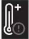 | Strumento di misura troppo caldo o troppo freddo | Lasciare che lo strumento di misura raggiunga la temperatura normale. |
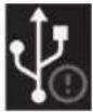 | Collegamento USB o cavo USB difettoso | Verificare se lo strumento di misura si possa collegare ad un altro computer. In caso negativo, inviare lo strumento di misura ad un Centro Assistenza Clienti autorizzato Bosch. |
| Lo strumento di misura non si può collegare ad un computer. | Avvertenza:utilizzare sempre il cavo USB fornito in dotazione. | |
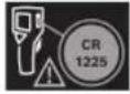 | Pila a bottone scarica Sostituire la pila a bottone (vedi «Sostituzione della pila a bottone (vedere fig. C)», Pagina 72). Confermare la sostituzione con «OK» premendo il tasto multifunzione (17) al centro. | |
Explanation of definitions
For further information, visit www.bosch-professional.com/thermal.
Infrared thermal radiation
Infrared thermal radiation is electromagnetic radiation emitted by any body with a temperature above 0 Kelvin (-273 °C). The amount of radiation depends on the temperature and the emissivity of the body.
Emissivity
The emissivity of an object depends on the material and structure of its surface. This value indicates the amount of infrared thermal radiation emitted by the object compared to an ideal radiating body (black body, emissivity ε = 1) and is therefore a value between 0 and 1.
Thermal bridge
A thermal bridge is defined as a point in the external wall of a building where, due to the construction, a high heat loss occurs locally.
Thermal bridges can lead to an increased risk of mold.
Reflected temperature / Reflectivity of an object
The reflected temperature consists of thermal radiation that does not come from the object itself. Depending on the structure and material, ambient radiation is reflected in the object to be measured and thus alters the actual measurement result.
Distance from the object
The distance between the object to be measured and the measuring instrument affects the size of the surface area detected for each pixel. As the distance from the object increases, larger and larger objects can be detected.
| Distanza (m) Dimensioni pixel ad infrarossi (mm) | Area ad infrarossi, larghezza × altezza (m) |
| 0,30 1,14 ~ 0,29 × 0,22 | |
| 0,55 2,08 ~ 0,53 × 0,40 | |
| 1,00 3,79 ~ 0,97 × 0,73 | |
| 2,00 7,58 ~ 1,94 × 1,46 | |
| 5,00 18,95 ~ 4,85 × 3,64 |
Maintenance and service
Maintenance and cleaning
Store and transport the measuring instrument only in a suitable container, such as the original packaging.
Always keep the measuring instrument clean. A contaminated infrared sensor (5) can impair measurement accuracy.
During cleaning, no liquid must penetrate the measuring instrument.
Do not attempt to remove dirt from the infrared sensor (5), the camera (3), the work light (4), or the laser beam exit aperture (2) with sharp objects. Do not wipe the infrared sensor or the camera (risk of scratching).
Clean regularly, especially the surfaces of the laser beam exit, paying particular attention to the presence of lint.
If you wish to perform a new calibration of the measuring tool, contact an authorized Bosch Service Center.
If the tool needs to be repaired, send it in its original packaging.
The measuring tool contains no parts that the user can service. Opening the housing
can irreparably damage the measuring tool.
Replacing the button battery (see figure C)
Open the cover (11).
Unscrew the screw (10) of the button battery holder. Pull the button battery holder (9) out of the measuring tool.
Replace the button battery. After insertion, retighten the screw (10) of the button battery holder.
After-sales service and technical advice
The after-sales service answers your questions regarding the repair and maintenance of your product as well as spare parts. Exploded views and information on spare parts can also be found at: www.bosch-pt.com
The Bosch team responsible for application advice will help you with questions about our products and their accessories.
When making inquiries or ordering spare parts, always quote the 10-digit product code found on the product's identification plate.
Italy
Tel.: (02) 3696 2314
E-Mail: pt.hotlinebosch@it.bosch.com
Further service addresses are listed below:
www.bosch-pt.com/serviceaddresses
Transport
The recommended lithium-ion rechargeable batteries are subject to legal requirements for dangerous goods. The rechargeable batteries can be transported by road by the user without further precautions.
When shipping via third parties (e.g., air transport or freight forwarder), special requirements regarding packaging and labeling must be observed. In this case, an expert for dangerous goods must be consulted for the preparation of the item to be shipped.
Ship rechargeable batteries only if the housing is not damaged. Cover exposed contacts with adhesive tape and pack the rechargeable battery so that it does not move in the packaging. Also observe any additional national regulations.
Disposal

Measuring tools, batteries/rechargeable batteries, accessories, and packaging should be disposed of/recycled in an environmentally friendly manner.
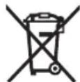
Do not dispose of measuring tools or batteries/rechargeable batteries in household waste.
Only for EU countries:
Unusable measuring tools and defective or used batteries/rechargeable batteries must be disposed of separately. Use the appropriate collection systems.
In the event of improper disposal, waste electrical and electronic equipment may have harmful effects on the environment and human health due to the possible presence of hazardous substances.
Batteries/rechargeable batteries:
For lithium-ion batteries:
Observe the warnings in the "Transport" section (see "Transport", page 72).
Dutch
Safety Instructions

All instructions must be read and observed to work safely and without danger with the measuring tool. If the measuring tool is not used according to the
available instructions, the integrated safety features in the measuring tool may be impaired. Never make warning stickers on the measuring tool illegible. KEEP THESE INSTRUCTIONS CAREFULLY AND INCLUDE THEM WHEN PASSING ON THE MEASURING TOOL.
▶ Caution – if other than the specified operating or adjustment devices are used or other methods are carried out, this can result in dangerous exposure to radiation. - The measuring tool is equipped with a laser warning label (indicated on the representation of the measuring tool on the page with illustrations). If the text on the laser warning label is not in your language, stick the provided sticker in your own language over it before first use.

Do not point the laser beam at persons or animals and do not look into the direct or reflected laser beam yourself. This can blind persons, cause accidents, or damage the eye.
If laser radiation hits the eye, the eyes must be consciously closed and the head must be immediately moved out of the beam. ▶ Do not make any modifications to the laser device. - Do not use the laser glasses (accessory) as safety glasses. The laser glasses serve to better recognize the laser beam; however, they do not protect against laser radiation.
- Do not use the laser viewing glasses (accessory) as sunglasses or while driving. The laser viewing glasses do not provide full UV protection and reduce color perception. Have the measuring tool repaired only by qualified trained personnel and only with original replacement parts. This ensures that the safety of the measuring tool is maintained. Do not allow children to use the laser measuring tool without supervision. They could accidentally blind other people or themselves. ▶ Do not operate the measuring tool in an environment where there is a risk of explosion and where flammable liquids, flammable gases, or flammable dust are present. Sparks may be generated in the measuring tool that could ignite the dust or vapors. ▶ Do not modify or open the battery. There is a risk of short circuit. If the battery is damaged or used incorrectly, vapors may be released. The battery can catch fire or explode. Ensure an adequate supply of fresh air and seek medical attention if you experience any discomfort. The vapors can irritate the respiratory tract. If the battery is used incorrectly or is damaged, flammable liquid may leak from the battery. Avoid contact with it. In case of accidental contact, rinse with water. If the liquid gets into the eyes, also consult a doctor. Leaked battery fluid can cause skin irritation or burns. ▶ The battery can be damaged by pointed objects, such as nails or screwdrivers, or by external force. An internal short circuit can occur, causing the battery to burn, smoke, explode, or overheat. Keep the unused battery away from paper clips, coins, keys, nails, screws, or other small metal objects that could bridge the contacts. A short circuit between the battery contacts can cause burns or fire.
- Use the battery only in products from the manufacturer. Only in this way is the battery protected against dangerous overload. ▶ Charge the batteries only with chargers recommended by the manufacturer. A charger that is suitable for one type of battery may pose a fire risk when used with other batteries.

Protect the battery from heat, for example from continuous sunlight, fire, dirt, water, and moisture. There is a risk of explosion and short circuit.

WARNING
74 | English


Ensure that the button cell does not get into the hands of children. Button cells are dangerous.
Button cells must never be swallowed or inserted into other body orifices. If you suspect that a button cell has been swallowed or inserted into another body orifice, seek medical attention immediately. Swallowing a button cell can cause severe internal injuries and death within 2 hours. ▶ When replacing the button cell, ensure it is done by a qualified person. There is a risk of explosion. - Use only the button cells specified in these instructions. Do not use other button cells or other power sources. ▶ Do not attempt to recharge the button cell or short-circuit it. The button cell may leak, explode, catch fire, and cause injury. Discharged button cells must be removed and disposed of properly. Discharged button cells may leak and damage the product or cause injury. ▶ Do not heat the button cell or throw it into a fire. The button cell may leak, explode, catch fire, and cause injury. ▶ Do not damage the button cell or take it apart. The button cell may leak, explode, catch fire, and cause injury. ▶ Do not bring a damaged button cell into contact with water. Leaking lithium can produce hydrogen with water, which can lead to fire, explosion, or injury. - Do not use the measuring tool if the button cell compartment cannot be closed properly and completely. Remove the button cell and have the measuring tool repaired. ▶ High temperature differences in a thermal image can cause even high temperatures to be displayed in a color associated with low temperatures. Contact with such a surface can result in burns. ▶ Correct temperature measurements are only possible when the set emissivity and the emissivity of the object match. Objects may be displayed with too high or too low temperatures, which could lead to a hazard upon contact. Do not point your measuring tool directly at the sun or at powerful CO₂ lasers. This can damage the detector. ▶ Protect the measuring tool, especially the camera and infrared lens parts, from moisture, snow, dust, and dirt. The receiver lens could fog up or become dirty, falsifying measurement results. Incorrect device settings as well as other atmospheric influences can lead to incorrect measurements. Objects may be displayed with too high or too low temperatures
which could lead to a hazard upon contact.
Description of product and operation
Observe the illustrations at the front of the operating instructions.
Intended use
This thermal imaging camera is intended for non-contact measurement of surface temperatures.
The displayed thermal image shows the temperature distribution of the field of view of the thermal imaging camera, making it possible to display temperature deviations in a color-differentiated manner.
With proper use, surfaces and objects can be examined contactlessly for temperature differences or conspicuous temperature behavior, in order to make building elements and/or any weak points visible, including:
- insulation (e.g., detecting thermal bridges)
- active central heating and hot water pipes (e.g., underfloor heating) in floors and walls
- overheated electrical components (e.g., fuses or terminals)
- defective or damaged machine parts (e.g., overheating due to defective ball bearings).
The measuring tool is not suitable for temperature measurement of gases.
The measuring tool must not be used for medical purposes on humans.
For medical applications on animals, obtain information at www.bosch-professional.com/thermal.
The measuring tool is suitable for indoor and outdoor use.
This product is a laser product for consumers in accordance with EN 50689.
The light of this measuring tool is intended for illuminating the immediate work area of the measuring tool for taking photos and is not intended as a permanent work lamp.
The laser point must not be used as a laser pointer. It is intended solely for marking the measuring plane.
Illustrated components
The components are numbered as shown in the illustration of the measuring tool on the illustration page.
(1) Protective cap (2) Opening for laser beam (3) Visual camera (4) Work light (5) Infrared sensor (6) Measurement pause/start button (7) Battery compartment (8) Laser warning label
(9) Button cell holder
(10) Button cell holder screw
(11) Cover for USB connection and button cell holder
(12) USB Type-C ® connection a)
(13) Laser button
(14) Battery/battery adapter release button
(15) Battery b)
(16) USB Type-C ® cable b)
(17) Multifunction button
(18) On/off button/Back button
(19) Display
(20) Serial number
(21) Battery adapter sleeve
(22) Batteries b)
(23) Battery adapter cap
a) USB Type-C® and USB-C® are trademarks of the USB Implementers Forum.
b) Not all accessories shown and described are included as standard.
Indicators
(a) Emission level indicator
(b) Reflected temperature indicator
(c) Average temperature indicator
(d) Memory full symbol
(e) Work light symbol
(f) Laser symbol
(g) Charge indicator
(h) Maximum surface temperature indicator in the measuring range
(i) Scale
(j) Minimum surface temperature indicator in the measuring range
(k) Temperature scale lock symbol
(I) Coldspot indication (by way of example)
(m) Crosshair with temperature indication
(n) Hotspot indication (by way of example)
(o) Menu symbol
Technical data
| Warmtebeeldcamera GTC 12V-450-13 | |
| Productnummer | 3 601 K83 900 |
| Resolutie infraroodsensor 256 × 192 px | |
| Thermische gevoeligheidA) | ≤ 50 mK |
| Spectraalbereik 8-14 μm | |
| Gezichtsveld (FOV)A) | 55,6° × 42° |
| Ruimtelijke resolutie (IFOV) 3,79 mrad | |
| BrandpuntsafstandA) | ≥ 0,5 m |
| Focus vast | |
| Beeldherhalingsfrequentie warmtebeeld ≤ 9 Hz | |
| Meetbereik oppervlaktetemperatuurA) | -20 ... +450 °C |
| Meetnauwkeurigheid oppervlaktetemperatuurA(B)C) | |
| >0 °C ... ≤ +100 °C) | ±2 °C |
| >+100 °CE) | ±2 % |
| Temperatuurresolutie 0,1 °C | |
| Displaytype TFT | |
| Displaygrootte 2,8" | |
| Resolutie display 480 × 360 px | |
| Resolutie geïntegreerde visuele camera 2 MP (640 × 480 px) | |
| Beeldformaat .jpg | |
| Opgeslagen elementen per opslagproces 1 × warmtebeeld (screenshot),1 × visueel echt beeld incl. temperatuurwaarden (metagegevens) | |
| Max. aantal foto's in intern fotogeheugen 500 | |
| Max. gebruikshoogte boven referentiehoogte 2000 m | |
| Vervuilingsgraad volgens IEC 61010-1 | 2F) |
76 | English
Thermal imaging camera GTC 12V-450-13
| Relatieve luchtvochtigheid max. A) | 90 % |
| Laserklasse 2 | |
| Lasertype < 1 mW, 645–660 nm | |
| Divergentie van laserstraal 1,5 mrad (volledige hoek) | |
| Energievoorziening | |
| - Accu (Li-lon) 12 V | |
| - Batterijen (alkaline met batterijadapter) 4 × 1,5 V LR6 (AA) | |
| - Oplaadbare batterijen (NiMH met batterijadapter) 4 × 1,2 V HR6 (AA) | |
| Gebruiksduur G) | |
| - Accu (Li-lon) H(i) | 8 h |
| - Batterijen (alkaline) 4 h | |
| Energievoorziening systeemtijd CR1225 (3-V-lithium-batterij) | |
| USB-standaard 2.0 | |
| USB-interface USB Type-C | |
| Gewicht J) | 0,354 kg |
| Afmetingen (lengte × breedte × hoogte) K) | 89 × 79 × 209 mm |
| Beschermklasse (uitgezonderd accu/(oplaadbare) batterijen,rechtop staand) | IP54 |
| Aanbevolen omgevingstemperatuur bij het opladen 0 °C ... +35 °C | |
| Toegestane omgevingstemperaturen | |
| - bij het gebruik -10 °C ... +50 °C | |
| - bij opslag met accu -20 °C ... +50 °C | |
| - bij opslag zonder accu -20 °C ... +70 °C | |
| Aanbevolen accu's | GBA 12V... |
| Aanbevolen opladers | GAL 12...GAX 18... |
A) according to VDI 5585 standard (average value)
B) At an ambient temperature of 20-23 °C and an emissivity of ≥ 0.95, measuring distance: 1 m, operating time: > 5 min, aperture of 150 mm, with work light and laser switched off
C) plus application-dependent deviation (e.g., reflection, distance, ambient temperature)
D) Applies to the center point, for all other pixels an additional ±1 °C
E) Applies to the center point, for all other pixels an additional ±1 %
F) Only non-conductive contamination occurs, but temporary conductivity may be expected due to condensation.
G) With work light switched off and average display brightness
H) depending on battery used
I) at an ambient temperature of 20-30 °C
J) Weight without battery/battery adapter/batteries
K) With GBA 12V 2.0Ah or battery adapter
The serial number (20) on the type plate serves for clear identification of your measuring tool.
Power supply for the measuring tool
The measuring tool can be operated either with a Bosch Li-ion battery, with conventional batteries, or with conventional rechargeable NiMH batteries.
Operation with battery (see figure A)
- Use only the chargers specified in the technical data. Only these chargers are matched to the Li-ion battery that must be used with your measuring tool.
Note: Lithium-ion batteries are supplied partially charged due to international transport regulations. To ensure full battery capacity, fully charge the battery before first use.
To insert the charged battery (15), slide it into the battery compartment (7) until it audibly clicks into place.
To remove the battery (15), press the release buttons (14) and pull the battery out of the battery compartment (7). Do not use force.
Operation with batteries (see figure B)
For operation of the measuring tool, the use of alkaline batteries or rechargeable NiMH batteries is recommended.
The batteries are placed in the battery adapter.
The battery adapter is intended exclusively for use in the corresponding Bosch measuring tools and must not be used with power tools.
To insert the batteries, slide the sleeve (21) of the battery adapter into the battery compartment (7). Insert the batteries into the sleeve according to the illustration on the end cap (23). Slide the end cap over the sleeve until it audibly clicks into place.
To remove the batteries (22), press the release buttons (14) on the end cap (23) and pull off the end cap. Remove the batteries. To remove the inner sleeve (21) from the battery compartment, reach into the sleeve and pull it out of the measuring tool while applying slight pressure to the side wall.
Always replace all batteries or rechargeable batteries at the same time. Use only batteries or rechargeable batteries from one manufacturer and with the same capacity.
Remove the (rechargeable) batteries from the measuring tool if you will not be using it for an extended period. The (rechargeable) batteries may corrode if stored in the measuring tool for a long time.
Tips for optimal handling of the rechargeable battery
Protect the rechargeable battery from moisture and water.
Store the rechargeable battery only at temperatures between -20 °C and 50 °C. For example, do not leave the rechargeable battery in the car in summer.
A significantly shorter operating time after charging indicates that the rechargeable battery is worn out and must be replaced.
Observe the notes regarding disposal.
Operation
▶ Protect the measuring tool from moisture and direct sunlight. Do not expose the measuring tool to extreme temperatures or temperature fluctuations. For example, do not leave it in the car for extended periods. In case of large temperature fluctuations, allow the measuring tool to acclimate to the ambient temperature before use. Extreme temperatures or temperature fluctuations can
adversely affect the accuracy of the measuring tool.
Ensure proper acclimatization of the measuring tool. In case of strong temperature fluctuations, the acclimatization time can be up to 60 minutes. This can occur, for example, when you store the measuring tool in a cold car and then take a measurement in a warm building. Avoid severe impacts or drops of the measuring tool. After strong external influences or if you notice any irregularities in functionality, have the measuring tool checked by an authorized Bosch customer service.
Initial Operation
When switching on for the first time
When the measuring tool is switched on for the first time or after resetting to factory settings, some basic settings must be performed. Select the desired values by pressing up, down, left, or right on the multi-function button (17). Press the center of the multi-function button (17) to confirm your selection. Once you have confirmed the selection, the next setting will appear on the display. The status bar at the top shows the total number and the number of remaining settings.
The following basic settings are available:
-
Switching on/off
For measuring, open the protective cap (1). During work, ensure that the infrared sensor is not blocked or covered.
To switch on the measuring tool, press the on/off button (18). A start sequence appears on the display (19). After the start sequence, the measuring tool immediately begins measuring and continues continuously until it is switched off.
Note: In the first few minutes, the measuring tool may adjust itself more frequently because the sensor and ambient temperatures have not yet equalized. The renewed sensor adjustment enables accurate measurement.
During this time, the temperature display may be marked with \~. This effect is intensified with strong fluctuations in ambient temperature. Therefore, switch on the measuring tool several minutes before starting the measurement, if possible, so that it can thermally stabilize.
To switch off the measuring tool, press the on/off button (18) for more than 1 second. The measuring tool saves all settings and then switches off. Close the protective cap (1) for safe transport of the measuring tool.
78 | English
In the main menu, you can choose whether and after what time the measuring tool should switch off automatically (see "Main menu", Page 80).
If the battery or the measuring tool is outside the operating temperature specified in the technical data, the measuring tool will switch off automatically after a brief warning (see "Errors – causes and remedies", Page 82). Allow the measuring tool to reach the correct temperature and then switch it on again.
Navigating in the various menus
Navigating in the various menus of the measuring tool:
- Call up the menu bars: press the center or left on the multi-function button (17). The right and left menu bars appear on the display, and the main menu is highlighted.
- In the left menu bar, browse/navigate in the main menu: press up, down, left, or right on the multi-function button (17).
- To go to the left or right menu bar: press left or right on the multi-function button (17).
- To confirm the selection/go to the submenu: press the center of the multi-function button (17).
- To return from a submenu to a higher menu: press the back button (18).
Measurement preparation
Setting the emissivity for surface temperature measurements
The emissivity of an object depends on the material and the structure of its surface. It indicates how much infrared heat radiation the object emits compared to an ideal heat radiator (black body, emissivity = 1) and accordingly has a value between 0 and 1.
To determine the surface temperature, the natural infrared heat radiation emitted by the object at which the measuring tool is aimed is measured contactlessly. For correct measurements, the emissivity set on the measuring tool must be checked before each measurement and adjusted to the measuring object if necessary.
The emissivities preset in the measuring tool are reference values.
You can select one of the preset emissivities or enter a precise numerical value. Set the desired emissivity via the menu →
(see "Main menu", page 80).
▶ Correct temperature measurements are only possible when the set emissivity and the emissivity of the object match.
The lower the emissivity, the greater the influence of the reflected temperature on the measurement result. Therefore, always adjust the reflected temperature when changing the emissivity. Set the reflected temperature via the menu
→ (see "Main menu", page 80).
Apparent temperature differences displayed by the measuring tool may be due to different temperatures and/or different emissivities. With strongly different emissivities, the displayed temperature differences can clearly deviate from the actual differences.
If multiple measuring objects of different materials or structures are within the measuring range, the displayed temperature values are only accurate for the objects that match the set emissivity. For all other objects (with different emissivities), the displayed color differences can be used as an indication of temperature relationships.
Notes on measuring conditions
Strongly reflective or shiny surfaces (e.g., shiny tiles or bare metals) can significantly distort or obstruct the displayed results. If necessary, cover the measuring surface with a dark, matte adhesive tape that is a good heat conductor. Allow the tape to reach the surface temperature briefly.
For reflective surfaces, pay attention to a favorable measuring angle so that reflected thermal radiation from other objects does not distort the result. For example, when measuring vertically from the front, the reflection of your own body heat can obstruct the measurement. On an even surface, the outlines and temperature of your body could be displayed (reflected value), which do not correspond to the actual temperature of the measured surface (emitted value or true value of the surface).
Measurement through transparent materials (e.g., glass or transparent plastics) is not possible due to the principle.
The measurement results become more accurate and reliable the better and more stable the measuring conditions are. Not only strong temperature fluctuations of the environment are relevant, but also strong fluctuations in the temperatures of the measured object can hinder accuracy.
Infrared temperature measurement is obstructed by smoke, steam/high humidity, or dusty air.
Tips for better measurement accuracy:
- Move as close as possible to the measuring object to minimize interfering factors between you and the measuring surface.
- Ventilate indoor rooms before measurement, especially when the air is polluted or very misty. After ventilating, allow the room to reach its usual temperature again.
Marking the measuring point
Do not point the laser beam at people or animals, and do not look into the laser beam yourself, even from a great distance.
The measuring tool is equipped with a laser to mark the measuring point.
Press and hold the laser button (13). The laser symbol (f) appears in the status bar, and a red circle appears around the crosshair (m). At a distance of 1 m, the laser and crosshair coincide exactly. When you release the laser button (13), the laser is switched off.
Temperature classification according to the scale
On the right side of the display, the temperature scale (i) is shown. The values at the very top and bottom are based on the maximum temperature (h) or minimum temperature (j) recorded in the thermal image.
For the temperature scale, 99.99% of all pixels are analyzed. The assignment of a color to a temperature value in the image is evenly distributed (linear).
Using the different colors, temperatures within these two boundary values can be classified. For example, a temperature that lies exactly between the maximum and minimum values is assigned to the middle color range of the temperature scale.
To determine the temperature of a specific area, move the measuring tool so that the crosshair with temperature display (m) is aimed at the desired point or area. In the automatic setting, the color spectrum of the temperature scale is always linearly (i.e., evenly) distributed over the entire measuring range within the maximum or minimum temperature.
The measuring tool displays all measured temperatures in the measuring range in proportion to each other. If, in a certain area, for example in a colored display, the heat is shown in a bluish color in the color palette, this means that the bluish areas belong to the colder measured values in the current measuring range. However, these areas can still be in a temperature range that could potentially result in injury. Therefore, always pay attention to the displayed temperatures on the temperature scale or directly at the crosshair.
Functions
Take note of the information regarding navigation in the various menus (see "Navigating in the various menus", Page 78).

Illuminating the measuring object
The measuring tool is equipped with a work light (4). It is intended for illuminating the immediate work area of the measuring tool for taking photos and is not intended as a permanent work lamp.
To switch the work light on or off, call up the left menu bar. Scroll to the menu item / and confirm your selection. When the work light is switched on, this is indicated in the status bar.
The light automatically switches off after 2 minutes to avoid affecting the accuracy of the measurement.
The automatic switch-off time can be set in the menu under .
Overlay of thermal and real image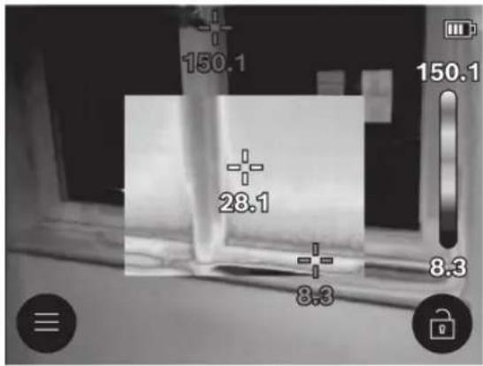
For better orientation (= spatial arrangement of the displayed thermal image), a visual real image can also be switched on in balanced temperature ranges.
Note: The thermal and real images overlap exactly at a distance of 1 m. At different distances to the measuring object, a displacement between the thermal and real images can occur due to the principle. This displacement can be compensated with special Bosch applications. Information on the applications and their compatibility can be found on the product page of the measuring tool or at www.bosch-professional.com/thermal.
The measuring tool offers you the following functions:
- 100% infrared image
Only the thermal image is displayed.

The displayed thermal image is superimposed transparently over the real image. This allows objects to be better recognized.
To activate/deactivate the setting, call up the left menu bar and scroll to the menu item
/ . Confirm your selection by pressing the multifunction button (17) in the center.
Picture-in-picture
The displayed thermal image is cropped and the surrounding area is shown as a real image. This setting improves the spatial layout of the measuring range.
To activate/deactivate the setting, call up the left menu bar and scroll to the menu item
80 | English
/ . Confirm your selection by pressing the multifunction button (17) in the center.
Adjusting the color display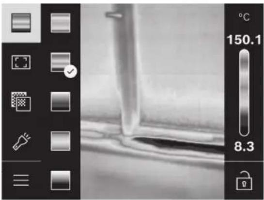
Depending on the measuring situation, different color palettes can simplify the analysis of the thermal image and display objects or the status more clearly on the screen. The measured temperatures are not affected by this. Only the display of the temperature values changes.
To change the color palette, call up the menu bar and scroll to the menu item "Color palette". Confirm your selection by pressing the multifunction button (17) in the center.
Lock the scale
The adjustment of the color distribution in the thermal image happens automatically, but can be fixed by pressing right and then in the middle on the multi-function button (17). This makes it possible to compare thermal images taken under different temperature conditions (e.g., when checking multiple rooms for cold bridges), or to hide an extremely cold or hot object in the thermal image that would otherwise distort the image (e.g., a radiator as a hot object when searching for cold bridges).
To switch the distribution scale back to automatic, call up the right menu bar and press in the middle on the multi-function button (17). The temperatures now behave dynamically again and adapt to the measured minimum and maximum values.
Main menu
Call up the left menu bar (see "Navigating in the different menus", page 78). To get to the main menu, press in the middle on the multi-function button (17).
- Under this menu item, you can delete the saved images individually or all at once.
-
- (a)
For some of the most common materials, you can choose from stored emissivity values. To make searching easier, the values are grouped into categories in the emissivity catalog. Select in the menu item
first the correct category and then the correct material. If you know the exact emissivity of your measuring object, you can also set it as a numerical value in the menu item.
• (b)
The setting of this parameter can improve the measurement result, especially for materials with low emissivity (= high reflection). In some situations (especially indoors), the reflected temperature corresponds to the ambient temperature. When objects with strongly deviating temperatures near highly reflective objects can influence the measurement, you must adjust this value. To do this, press left or right on the multi-function button (17).
-
To ensure high accuracy over the entire measuring range, measurement is carried out in 2 temperature ranges. In the measuring function, the measuring tool automatically selects the appropriate temperature range based on the temperature distribution in the thermal image. It is assessed how many measured values lie above a certain temperature threshold. If very small but hot objects are to be measured, it can happen that the low temperature range, which is unsuitable for high temperatures, is selected. This is indicated by the symbol \~ in front of the temperature display. In this case, switch to the measuring function <100 °C ... 450 °C> or <-20 °C ... 100 °C> in which the color distribution corresponds to the set temperature range. The setting is marked on the distribution scale with an arrow up or down.
-
- (m): /
The point appears in the center of the thermal image and shows you the measured temperature value at that location.
- (n): /
The hottest point (= measurement pixel) is marked by a red crosshair in the thermal image. This makes it easier to search for critical points (e.g., loose contact clamp in the switch cabinet).
• (I): /
The coldest point (= measurement pixel) is marked by a blue crosshair in the thermal image. This makes it easier to search for critical points (e.g., leaky spot at the window).
- (i): /
- (c): /
The average temperature (c) is displayed at the top left of the thermal image (average temperature of all measured values in the thermal image).
This can make it easier for you to determine the reflected temperature.
-
-
Under this menu item you can adjust the brightness of the display lighting.
•
Under this menu item you can choose the time interval for automatically switching off the work light when no button is pressed.
•
Under this menu item, you can select the time interval after which the measuring tool automatically switches off when no button is pressed. You can also deactivate the automatic switch-off by choosing the corresponding setting.
-
In this submenu, you can set the time and date as well as change their formats.
•
Under this menu item, you can select the language used on the display.
-
Under this menu item, you can reset the measuring tool to factory settings and permanently delete all data. This may take several minutes. Press the multifunction button on the right (17) to delete all files, or the multifunction button on the left (17) to cancel the process.
-
Under this menu item, you can view information about the measuring tool. You will find the serial number of the measuring tool and the installed software version. You can also find further information about the measuring tool and the software update.
To exit any menu and return to the standard display screen, you can also press the Measurement button (6).
Update measuring tool software
If desired, you can update the software of the measuring tool via the USB Type-C® port. Information on this can be found at:
www.bosch-professional.com/thermal-update.
Documenting measurement results
Saving measurement results
Immediately after switching on, the measuring tool starts measuring and continues to do so continuously until it is switched off.
To save an image, point the camera at the desired measuring object and press the measurement button (6). The image is saved in the internal memory of the measuring tool. The measurement is frozen and displayed on the screen. This allows you to view the image carefully and adjust it afterwards (e.g., the color palette). If you do not want to save the frozen image, start the measurement mode again with the measurement button (6).
If you want to save the image in the internal memory of the measuring tool, press the multifunction button (17) in the center.
Retrieving saved images
To retrieve saved thermal images, proceed as follows:
- Immediately after saving, press the multifunction button (17) in the center again. The preview image of the last saved photo now appears on the display.
- Alternatively, you can retrieve the saved photos under the menu item.
- To switch between the saved thermal images, press the multifunction button (17) on the right or left.
In addition to the thermal image, the visual image was also saved. To retrieve it, press the multifunction button (17) at the top or bottom.
After 5 seconds, the measuring tool switches to full screen. In full screen, the title bar indication disappears, so you can view all details of the thermal image.
By pressing the multifunction button (17) at the top and bottom, you can switch between the views.
Deleting saved images
To delete individual or all thermal images, press the multifunction button (17) in the center. A submenu opens.
- Here you can choose whether to delete only this image or all images. Confirm the choice by pressing the multifunction button (17) in the center.
For the choice, you can select from
Confirm the selection by pressing the multifunction button (17) in the center.
In this submenu, you can also view information about the emissivity and the reflected temperature.
Data fragments of the images remain in memory and could be reconstructed. For definitive deletion, choose in the main menu
→ .
Data transfer
Data transfer via USB interface
Open the cover (11) of the USB Type-C® connection. Connect the USB Type-C® connection (12) of the measuring tool to your computer using the supplied USB Type-C® cable (16).
Now switch on the measuring tool with the on/off button (18).
On your computer, open the file browser and select the drive GTC_450. The stored files can be copied from the internal memory of the measuring tool, moved to your computer, or deleted.
Once you have finished the desired process, disconnect the drive from the computer as standard and then switch
82 | Dutch
off the measuring tool again with the on/off button (18).
Note: Always eject the drive from your operating system first (eject drive), otherwise the internal memory of the measuring tool may be damaged. Remove the USB Type-C® cable and close the cover (11). Always keep the cover of the USB port closed so that no dust or splash water can enter the housing.
Note: Connect the measuring tool via USB only to a computer. Connecting to other devices may damage the measuring tool.
Note: The USB Type-C® interface is intended solely for data transfer. Batteries and rechargeable batteries cannot be charged here.
Post-processing of thermal images
You can post-process the saved thermal images with special Bosch applications. Information about the applications and their compatibilities can be found on the product page of the measuring tool or at www.bosch-professional.com/thermal.
Errors - causes and remedies
In the event of a malfunction, the measuring tool performs a restart and can then be used again. Otherwise, the following overview will help you with permanent error messages.
Error Cause Remedy
| Meetgereedschap kan niet ingeschakeld worden. | Accu/(oplaadbare) batterijen leeg | Laad de accu op of verwissel de batterijen. | |
 | Fout accu/(oplaadbare) batterijen | Verwissel de accu of batterijen. | |
 | Accu/(oplaadbare) batterijen te warm of te koud | Laat de accu op de juiste temperatuur komen of verwissel de accu of de batterijen. | |
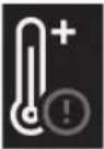 | Meetgereedschap te warm of te koud | Laat het meetgereedschap op de juiste temperatuur komen. | |
 | USB-aansluiting of USB-kabel defect | Controleer of het meetgereedschap met een andere computer kan worden verbonden. Als dit niet het geval is, stuurt het meetgereedschap naar een geautoriseerde Bosch-klantenservice op.Aanwijzing: Gebruik altijd de meegeleverde USB-kabel. | |
| Het meetgereedschap kan niet met een computer worden verbonden. | |||
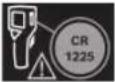 | Knoopcel leeg Vervang de knoopcel (zie „Knoopcel vervangen (zie afbeelding C)“, Pagina 83). Bevestig de wissel met "OK" door op het midden van de multifunctionele toets (17) te drukken. | ||
| Uitleg van begrippenMeer informatie vindt u opwww.bosch-professional.com/thermal.Infrarood-warmtestralingDe infrarood-warmtestraling is een elektromagnetische straling die door elk lichaam boven 0 Kelvin (-273 °C) wordt uitgestraald. De hoeveelheid straling is afhankelijk van de temperatuur en de emissiegraad van het lichaam.EmissiegraadDe emissiegraad van een object is afhankelijk van het materiaal en van de structuur van zijn oppervlak. Deze geeft aan | hoeveel infrarood-warmtestraling het object in vergelijking met een ideale warmtestraler (zwart lichaam, emissiegraad = 1 ) afgeeft en bedraagt dienovereenkomstig een waarde tussen 0 en 1.KoudebrugEen koudebrug is een plek bij de buitenmuur van een gebouw waar door de constructie een lokaal verhoogd warmteverlies ontstaat.Koudebruggen kunnen resulteren in een verhoogd risico op schimmelvorming. | ||
Explanation of terms
Infrared thermal radiation
Emissivity
Thermal bridge
Reflected temperature/reflectivity of an object
The reflected temperature is the thermal radiation that does not originate from the object itself. Depending on the structure and material, ambient radiation is reflected into the object being measured and thus falsifies the actual temperature result.
Object distance
The distance between the measuring object and the measuring tool influences the recorded surface size per pixel. With increasing object distance, you can record increasingly larger objects.
| Afstand (m) Grootte infra-roodpixels (mm) | Breedte × hoogte infraroodbereik (m) |
| 0,30 1,14 ~ 0,29 × 0,22 | |
| 0,55 2,08 ~ 0,53 × 0,40 | |
| 1,00 3,79 ~ 0,97 × 0,73 | |
| 2,00 7,58 ~ 1,94 × 1,46 | |
| 5,00 18,95 ~ 4,85 × 3,64 |
Maintenance and service
Maintenance and cleaning
Store and transport the measuring tool only in a suitable holder, such as the original packaging.
Always keep the measuring tool clean. A dirty infrared sensor (5) can impair measurement accuracy.
During cleaning, no liquid may enter the measuring tool.
Do not attempt to remove dirt from the infrared sensor (5), camera (3), work light (4), or laser opening (2) with pointed objects. Do not wipe over the infrared sensor and camera (risk of scratches).
In particular, clean the laser opening regularly and pay attention to lint.
If you want your measuring tool to be recalibrated, contact an authorized Bosch customer service.
Send the measuring tool for repair in the original packaging.
There are no user-serviceable parts inside the measuring tool. Opening the housing shell can destroy the measuring tool.
Replacing the button cell (see figure C)
Open the cover (11).
Unscrew the screw (10) of the button cell holder. Pull the button cell holder (9) out of the measuring tool. Replace the button cell. After inserting the button cell holder, tighten the screw (10) again.
Customer service and usage advice
Our customer service answers your questions about repair and maintenance of your product and about spare parts. Exploded views and information on spare parts can also be found at: www.bosch-pt.com
The Bosch advice team will be happy to help you with questions about our products and accessories.
When making inquiries and ordering spare parts, always provide the ten-digit product number from the product's type plate.
Netherlands
Tel.: (076) 579 54 54
Fax: (076) 579 54 94
E-mail: gereedschappen@nl.bosch.com
For more service addresses, see:
www.bosch-pt.com/serviceaddresses
Transport
The recommended lithium-ion batteries are subject to the requirements for the transport of dangerous goods. The batteries can be transported by the user on the road without further conditions.
When shipping by third parties (e.g., air transport or forwarding company), special requirements regarding packaging and labeling must be observed. In these cases, a dangerous goods expert must be consulted when preparing the shipment.
Only ship batteries if the housing is undamaged. Tape over exposed contacts and pack the battery so that it does not move in the packaging. Also observe any additional national regulations.
Disposal

Measuring tools, batteries, accessories, and packaging must be recycled in an environmentally responsible manner.
Do not dispose of measuring tools and batteries in household waste!
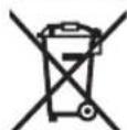
Only for EU countries:
Discarded measuring tools and defective or empty batteries must be disposed of separately. Use the collection systems provided for this purpose.
If waste electrical and electronic equipment is disposed of improperly, it can have harmful effects on the environment and public health due to the possible presence of hazardous substances.
Batteries:
Li-Ion:
Read and follow the instructions in the Transport section (see "Transport", page 83).
Danish
Safety Instructions

All instructions must be read and followed in order to work safely and without risk with the measuring tool. If the measuring tool is not used in accordance with the instructions provided, the function of the integrated protective measures in the measuring tool may be impaired. Ensure that warning signs are never made illegible on the measuring tool. KEEP THE INSTRUCTIONS AND BE SURE TO DELIVER THEM WITH THE MEASURING TOOL IF IT IS GIVEN TO OTHERS.
Caution – if any operating or adjustment devices other than those specified here are used, or other procedures are performed, dangerous radiation exposure may occur. The measuring tool is supplied with a laser warning sign (identified on the graphic page in the illustration of the measuring tool). If the text on the laser warning sign is not in your native language, stick the supplied label in your language over the existing text before the tool is used for the first time.

Do not point the laser beam at persons or animals, and never look directly into the direct or reflected laser beam. This can blind persons, cause accidents, or damage eyes.
If you get the laser beam in your eyes, close your eyes immediately and move your head out of the beam area at once.
Never make any modifications to the laser device.
Do not use the laser goggles (accessory) as protective goggles. The laser goggles make it easier to see the laser beam, but they do not protect against laser radiation.
Do not use the laser goggles (accessory) as sunglasses or in traffic. The laser goggles do not provide 100% protection against ultraviolet (UV) rays and reduce your ability to perceive and observe colors.
Ensure that repairs on the measuring tool are only carried out by qualified specialists and that only original spare parts are used. This ensures the greatest possible safety in connection with the measuring tool.
Do not allow children to use the laser measuring tool without supervision. They may unintentionally blind persons or themselves.
Do not use the measuring tool in explosive atmospheres where flammable liquids, gases, or dust are present. Sparks may be generated in the measuring tool, which can ignite the dust or vapors.
- Do not modify or open the battery. Risk of short circuit.
If the battery is damaged or used improperly, vapors may escape. The battery can ignite or explode.
Provide fresh air and seek medical attention if you feel unwell. The vapors can irritate the respiratory tract.
If the battery is used incorrectly or is damaged, flammable liquid may escape from the battery. Avoid contact with this liquid. If contact occurs, rinse with water. Seek medical attention if the liquid gets into your eyes. Battery fluid can cause skin irritation or burns.
- The battery can be damaged by sharp objects such as nails or screwdrivers, or by external force. An internal short circuit can occur, causing the battery to ignite, smoke, explode, or overheat.
Unused batteries must not come into contact with paper clips, coins, keys, nails, screws, or other small metal objects, as these can short-circuit the contacts. A short circuit between battery contacts increases the risk of injury in the form of burns.
Only use the battery in products from the manufacturer. Only in this way is the battery protected against dangerous overload.
Only charge the batteries with chargers recommended by the manufacturer. A charger suitable for one type of battery must not be used with other batteries – fire hazard.
Protect the battery from heat (e.g., also from prolonged sunlight, fire, dirt, water, and moisture). There is a risk of explosion and short circuit.
WARNING

Ensure that the button cell battery is inaccessible to children. Button cells are dangerous.
Button cells must never be placed in the mouth or inserted into other body openings. If you suspect that the button cell battery has been swallowed or inserted into another body opening, seek medical attention immediately. A swallowed button cell can cause severe internal burns and death within 2 hours.
When replacing button cells, ensure that the button cell is replaced professionally and correctly. Risk of explosion.
Only use the button cells specified in this operating manual. Do not use other button cells or any other power supply.
Do not attempt to recharge the button cell, and do not short-circuit it. The button cell may leak, explode, burn, and cause personal injury.
Remove and dispose of discharged button cells in accordance with the regulations. Discharged button cells may leak and thereby damage the product or cause personal injury.
Do not allow the button cell to overheat, and do not throw it into fire. The button cell may leak, explode, burn, and cause personal injury.
The button cell must not be damaged or taken apart. The button cell may leak, explode, burn, and cause personal injury. A damaged button cell must not come into contact with water. Escaping lithium in contact with water can form hydrogen and thereby cause a fire, an explosion, or personal injury. ▶ Do not continue to use the measuring tool if the button cell holder can no longer be closed properly and completely. Remove the button cell and have the measuring tool repaired. ▶ Large temperature differences in a thermal image can cause even high temperatures to be displayed with a color associated with low temperatures. If you touch such a surface, it can result in burns. Correct temperature measurements are only possible if the set emissivity matches the emissivity of the object. Objects can be displayed with too high or too low a temperature, which may pose a hazard upon contact. ▶ Do not point the measuring tool directly at the sun or at CO₂ high-power lasers. This can damage the detector. Protect the measuring tool from moisture, snow, dust, and dirt, especially in the areas around the camera and the infrared lens. The receiving lens can become fogged or dirty and falsify the measurement results. Incorrect settings and other atmospheric influencing factors can lead to incorrect measurement results. Objects can be displayed with too high or too low a temperature, which may pose a hazard upon contact.
Product Description and Performance
Pay attention to the illustrations at the beginning of the operating instructions.
Intended Use
The thermal camera is intended for non-contact measurement of surface temperatures.
The displayed thermal image indicates the temperature distribution in the camera's field of view and shows temperature differences with different colors.
If the camera is used correctly, it is thus possible to display temperature differences and fluctuations on surfaces and objects without having to touch them. In this way, you can make building components and weak points visible. This includes, among other things:
- insulation against heat and cold (e.g., detection of thermal bridges)
- active heating and hot water pipes (e.g., underfloor heating) in floors and walls
- overheated electrical components (e.g., fuses or terminals)
- defective or damaged machine parts (e.g., overheating due to defective ball bearings). The measuring tool is not suitable for temperature measurement of gases.
The measuring tool must not be used for human medical purposes. You can find more information about veterinary medical use at www.bosch-professional.com/thermal.
The measuring tool can be used both indoors and outdoors. This product is a consumer laser product according to EN 50689.
The light on the measuring tool is intended to illuminate the tool's immediate work area during measurements and cannot be used as permanent work lighting. The laser point must not be used as a laser pointer. It should only be used for marking the measuring surface.
Illustrated components
The numbering of the illustrated components refers to the illustration of the measuring tool on the illustration page.
(1) Protective cap (2) Laser radiation outlet opening (3) Visual camera (4) Work light (5) Infrared sensor (6) Pause/start measurement button (7) Battery compartment (8) Laser warning sign (9) Button cell battery holder
(10) Screw for button cell battery holder
(11) Cover for USB socket and button cell battery holder
(12) USB Type-C® socket a)
(13) Laser button
(14) Unlock button for battery/battery adapter
(15) Battery b)
(16) USB Type-C ® cable b)
(17) Multifunction button
(18) On/off button/back button
(19) Display
(20) Serial number
(21) Socket for battery adapter
(22) Batteries b)
(23) Cover for battery adapter
a) USB Type-C® and USB-C® are trademarks of USB Implementers Forum. b) Accessories illustrated or described in the operating instructions are not included in the standard delivery.
Display elements
(a) Display of emissivity (b) Display of reflected temperature (c) Display of average temperature (d) Memory full symbol (e) Work light symbol (f) Laser symbol (g) Charge level indicator
86 | Danish
(h) Display of max. surface temperature in the measuring range (i) Scale (j) Display of min. surface temperature in the measuring range (k) Symbol for locking the temperature scale
(I) Display of cold spot (example) (m) Crosshair with temperature display (n) Display of hot spot (example) (o) Menu symbol
Technical data
| Termisk kamera GTC 12V-450-13 | |
| Varenummer | 3 601 K83 900 |
| Opløsning infrarød sensor 256 × 192 px | |
| Termisk følsomhed A) | ≤ 50 mK |
| Spektralområde 8-14 μm | |
| Synsfelt (FOV) A) | 55,6° × 42° |
| rumlig opløsning (IFOV) 3,79 mrad | |
| Fokusafstand A) | ≥ 0,5 m |
| Fokus fast | |
| Billedgentagelseshastighed varmebillede ≤ 9 Hz | |
| Måleområde overfladetemperatur A) | -20 ... +450 °C |
| Målenøjagtighed overfladetemperatur A)(B)(C) | |
| >0 °C ... ≤ +100 °CD) | ±2 °C |
| >+100 °CE) | ±2 % |
| Temperaturopløsning 0,1 °C | |
| Displaytype TFT | |
| Displaystørrelse 2,8" | |
| Opløsning, display 480 × 360 px | |
| Opløsning af integreret visuelt kamera 2 MP (640 × 480 px) | |
| Billedformat .jpg | |
| Gemte elementer pr. lagring 1 × varmebillede (screenshot), | 1 × visuelt realbillede inkl. temperaturværdier (metadata) |
| Maks. antal billeder i intern billedhukommelse 500 | |
| Maks. anvendelseshøjde over referencehøjde 2000 m | |
| Tilsmudsningsgrad iht. IEC 61010-1 2 | F) |
| Relativ luftfugtighed maks. A) | 90 % |
| Laserklasse | 2 |
| Lasertype | < 1 mW, 645–660 nm |
| Laserstrålens divergens | 1,5 mrad (360°-vinkel) |
| Energiforsyning | |
| - Akku (lithium-ion) | 12 V |
| - Batterier (alkali-mangan med batteriadapter) | 4 × 1,5 V LR6 (AA) |
| - Akkuer (NiMH med batteriadapter) | 4 × 1,2 V HR6 (AA) |
| Driftsvarighed G) | |
| - Akku (lithium-ion) H)(I) | 8 t |
| - Batterier (alkaliske manganbatterier) | 4 t |
| Energiforsyning systemtid | CR1225 (3 V-lithium-batteri) |
| USB-standard | 2.0 |
| USB-interface | USB Type-C |
Thermal camera GTC 12V-450-13
| Vægtj) | 0,354 kg |
| Mål (længde × bredde × højde) K) | 89 × 79 × 209 mm |
| Kapslingsklasse (undtagen akku/batterier, i opret position) IP54 | |
| Anbefalet omgivelsestemperatur ved opladning 0 °C ... +35 °C | |
| Tilladte omgivelsestemperaturer | |
| - Ved drift -10 °C ... +50 °C | |
| - Ved opbevaring med akku -20 °C ... +50 °C | |
| - Ved opbevaring uden akku -20 °C ... +70 °C | |
| Anbefalede akkuer GBA 12V... | |
| Anbefalede ladere GAL 12... | GAX 18... |
A) According to standard VDI 5585 (average value)
B) At an ambient temperature of 20–23 °C and an emissivity of ≥ 0.95, measuring distance: 1 m, operating time: > 5 min., aperture of 150 mm, with work light and laser switched off
C) Plus application-related deviation (e.g., reflection, distance, ambient temperature)
D) Applies to the center point, and also to all other pixels ±1 °C
E) Applies to the center point, and also to all other pixels ±1 %
F) Only non-conductive contamination occurs, although occasional temporary conductivity due to condensation must be expected.
G) With work lighting switched off and medium display brightness
H) depending on the battery pack used
1) At an ambient temperature of 20-30 °C
J) Weight without battery pack/battery adapter/batteries
K) With GBA 12V 2.0Ah or battery adapter
The serial number (20) on the type plate is used for unambiguous identification of the measuring tool.
Power supply for the measuring tool
The measuring tool can be operated either with a Bosch lithium-ion battery pack, with standard batteries, or with standard NiMH rechargeable batteries.
Operation with battery pack (see figure A)
Only use the chargers listed in the technical data. Only these chargers are matched to the Li-ion battery pack used in your measuring tool.
Note: Lithium-ion battery packs are partially charged when shipped due to international transport regulations. To ensure full battery pack performance, fully charge the battery pack in the charger before first use.
To insert the charged battery pack (15), push the battery pack into the battery mount (7) until it audibly clicks into place.
To remove the battery (15), press the release buttons (14) and pull the battery out of the battery compartment (7). Avoid using force.
Operation with batteries (see figure B)
It is recommended to use alkaline manganese batteries or NiMH rechargeable batteries for the measuring tool.
Insert the batteries into the battery adapter.
The battery adapter is intended exclusively for use in the Bosch measuring tools for which it is designed and must not be used with power tools.
To insert the batteries, push the battery adapter's sleeve (21) into the battery compartment (7). Place the batteries into the sleeve as shown on the closing cap (23). Push the closing cap over the sleeve until it engages noticeably.
To remove the batteries (22), press the release buttons (14) on the closing cap (23) and pull the closing cap off. Take out the batteries. To remove the sleeve (21) from the battery compartment, grasp the sleeve and pull it out of the measuring tool while pressing lightly against the side wall.
Always replace all batteries or rechargeable batteries at the same time. Only use batteries or rechargeable batteries from the same manufacturer and with the same capacity.
Remove the batteries or rechargeable batteries from the measuring tool if they are not to be used for an extended period. Batteries and rechargeable batteries can corrode and discharge themselves if they remain in the measuring tool for a long time.
Tips for optimal handling of the rechargeable battery
Protect the rechargeable battery against moisture and water.
Store the rechargeable battery only in a temperature range from -20 °C to 50 °C. Do not store the rechargeable battery in the car, e.g., in summer.
When the operating time per charge is significantly reduced, this is a sign that the rechargeable batteries are worn out and need to be replaced.
Read and observe the notes regarding disposal.
Use
Protect the measuring tool against moisture and direct sunlight. Do not expose the measuring tool to extreme temperatures or temperature fluctuations. For example, do not leave it in the car for a long time. In the event of major temperature fluctuations, the measuring tool must be allowed to adjust to the ambient temperature before use. Extreme temperatures or temperature fluctuations can affect the accuracy of the measuring tool. Ensure that the measuring tool is properly acclimatized. In the event of severe temperature fluctuations, the acclimatization time can be up to 60 minutes. This can be the case, for example, if you store the measuring tool in a cold car and then take a measurement in a warm building. Do not subject the measuring tool to severe shocks or drops. After severe external influences and in the event of abnormal function, have the measuring tool checked by an authorized Bosch customer service.
Operation
Initial operation
When the measuring tool is used for the first time or after it has been reset to the factory settings, some basic settings must be made. Select the desired values by pressing the multi-function button (17) at the bottom, top, left, or right. Press the center of the multi-function button (17) to confirm the selected values. As soon as the selected values are confirmed, the next setting is shown on the display. The status bar at the top shows the total number and the remaining number of settings.
You can choose between the following basic settings:
Switching on/off
Flip up the protective cap (1) when you need to measure. During work, ensure that the infrared sensor is not closed or covered.
To switch on the measuring tool, press the on/off button (18). A start sequence is shown on the display (19). After the start sequence, the measuring tool immediately begins to measure. Measurement continues until the measuring tool is switched off again.
Note: In the first few minutes, it may happen that the measuring tool is calibrated more frequently, as the sensor and ambient temperature have not yet been calibrated. The new sensor calibration enables precise measurement.
During calibration, the symbol \~ is shown on the temperature display. If there are severe temperature fluctuations in the environment, this effect is intensified. Therefore, switch off the measuring tool for a few minutes before starting the measurement so that it can become acclimatized.
To switch off the measuring tool, press the on/off button (18) for > 1 s. The measuring tool saves all settings and then switches off. Close the protective cap (1) so that you can transport the measuring tool safely.
In the main menu, you can select whether and after how long the measuring tool should switch off (see "Main menu", page 90).
If the battery or the measuring tool is used outside the temperature range specified in the technical data, the measuring tool switches off automatically after giving a brief warning (see "Errors – causes and remedies", page 92). Allow the measuring tool to adjust to the ambient temperature, then switch it on again.
Navigating in the various menus
Navigating in the various menus of the measuring tool:
- Open the menu lists: Press the center or left side of the multi-function button (17). The left and right menu lists appear on the display, and the main menu is highlighted.
- To scroll through the left menu list/navigate in the main menu: Press the multi-function button (17) at the top, bottom, left, or right.
- Switch to the left or right menu list: Press the left or right part of the multi-function button (17).
- Confirm the selection/switch to the submenu: Press the center of the multi-function button (17).
- Switch to a higher-level menu from a submenu: Press the back button (18).
Measurement preparation
Set the emissivity for surface temperature measurements
An object's emissivity depends on the material and the surface structure. It indicates how much infrared thermal radiation the object emits compared to an ideal radiator (black body, emissivity ε = 1), and has a value between 0 and 1.
To determine the surface temperature, a non-contact measurement is performed of the natural infrared thermal radiation emitted by the object being aimed at. To obtain correct measurements, check the emissivity set on the measuring tool before each measurement and adjust it to the measuring object if necessary.
The emissivities preset in the measuring tool are only for guidance.
You can select one of the preset emissivities or enter a precise numerical value. Set the desired emissivity via the menu → (see "Main menu", Page 90).
- Correct temperature measurements are only possible if the set emissivity matches the object's emissivity.
The lower the emissivity, the greater the impact of the reflected temperature on the measurement result. Therefore, always adjust the reflected temperature when you change the emissivity. Set the reflected temperature via the menu
→ (see "Main menu", Page 90).
If the measuring tool displays temperature differences, this may be due to different temperatures and/or different emissivities. With very different emissivities, the displayed temperature differences may deviate clearly from the actual ones. If there are multiple measuring objects in different materials or with different structures in the measuring range, the displayed temperature values are only correct for the objects that match the set emissivity. For all other objects (with different emissivities), the displayed color differences can be used as an indication of the temperature conditions.
References regarding measuring conditions
Strongly reflective or shiny surfaces (e.g., shiny tiles or polished metals) can affect the displayed results, causing them to be incorrect. If necessary, cover the measuring surface with dark, matte, and thermally conductive tape. Allow the tape to acclimate briefly on the surface.
For reflective surfaces, ensure a favorable measuring angle so that the result is not falsified by reflected heat radiation from other objects. For example, the reflection of your body heat can affect the measurement if you measure vertically from the front. On smooth surfaces, the outline or temperature of your body may appear (reflected values), even though they do not correspond to the actual temperature of the measured surfaces (emitted value or real surface value).
Due to the measuring principle, it is not possible to measure through transparent materials (e.g., glass or transparent plastics).
The measurement results become more accurate and reliable the better and more stable the measuring conditions are. In this context, not only strong temperature fluctuations in the environment are relevant, but also strong temperature fluctuations in the measured objects can affect accuracy.
Infrared temperature measurement is affected by smoke, steam/high humidity, or dusty air.
Recommendations for better measurement accuracy:
- Get as close to the measuring object as possible to minimize interfering factors between you and the measuring surface.
- Ventilate the room before measuring, especially if the air is dirty or very humid. After ventilation, allow the room to acclimate until it returns to its normal temperature.
Marking the measuring spot
Do not point the laser beam at people or animals and do not look into the laser beam, even from a distance.
The measuring tool is equipped with a laser for marking the measuring spot.
Press and hold the laser button (13). The laser symbol (f) appears on the status bar, and a red circle is displayed around the crosshair (m). The overlap of the laser and crosshair covers exactly at a distance of 1 m. When you release the laser button (13), the laser turns off.
Interpreting the temperatures using the scale
On the right side of the display, the scale (i) is shown. The values at the upper and lower ends are based on the maximum temperature (h) and minimum temperature (j) recorded in the thermal image. For the scale, 99.99% of all pixels are evaluated. The assignment of a color to a temperature value in the image is uniform (linear).
Using the various color shades, temperatures can thus be assigned within these two extreme values. A temperature that lies exactly midway between the maximum and minimum values is assigned, for example, to the middle color range on the scale.
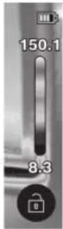
If you want to determine the temperature in a specific area, move the measuring tool so that the crosshairs with the temperature display (m) are aimed at the desired point or area. Under the automatic settings, the scale's color spectrum is continuously distributed linearly across the entire measuring range within the maximum and minimum temperatures (= uniform).
The measuring tool displays all measured temperatures in the measuring range in relation to each other. If the heat in an area, for example shown in color, appears bluish on the color palette, it means that the bluish area belongs to the colder measured values in the current measuring range. However, these areas can still lie in a temperature range that, under certain circumstances, can result in injuries. Therefore, always keep an eye on the displayed temperatures on the scale or directly on the crosshairs.
Functions
Follow the information on navigation in the various menus (see "Navigating in the various menus", page 88).

Illumination of the measuring object
The measuring tool is equipped with a work light (4). This light is intended to illuminate the direct work area of the measuring tool during recordings and cannot be used as a constant work light.
To turn the work light on/off, open the list on the left side. Scroll to the menu item /<LED
disabled>, and confirm the selection. When the work light is on, the status bar is displayed.
The light turns off automatically after 2 minutes to avoid affecting measurement accuracy.
You can change the automatic shut-off time in the menu under .
Overlay of thermal image and real image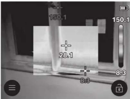
To ensure better orientation (= spatial allocation of the displayed thermal image), a visual real image can also be activated in balanced temperature ranges.
Note: The overlay of the real and thermal image matches exactly at a distance of 1 m. If you move away from the measuring object, a shift occurs between the real image and the thermal image. This shift can be compensated for with special Bosch apps. You can find information about apps and compatibility on the product page for the measuring tool or at www.bosch-professional.com/thermal.
The measuring tool offers the following options:
- 100% infrared image
Only the thermal image is displayed.

- Transparency
The displayed thermal image is overlaid transparently on the real image. This makes it easier to see objects. The setting is activated/deactivated by opening the list on the left side and scrolling to the menu item / . Press the center of the multi-function button (17) to confirm the selection.
- Picture-in-picture
The displayed thermal image is cropped, and the surrounding area is shown as a real image. This setting improves the allocation of the measurement area on site.
The setting is activated/deactivated by opening the list on the left side and scrolling to the menu item <Picture-in-picture
on>/ . Press the center of the multi-function button (17) to confirm the selection.
Adjusting the color display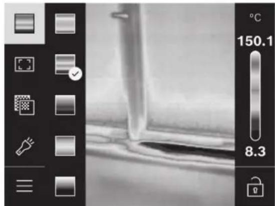
Depending on the measurement situation, different color palettes can simplify the analysis of the thermal image and display objects or conditions more clearly on the screen. The measured temperatures are not affected by this. Only the display of the temperature values changes.
Change the color palette by opening the side list and scrolling to the menu item "Color palette". Press the center of the multi-function button (17) to confirm the selection.
Locking the scale
The adjustment of the color distribution on the thermal image is automatic, but can be locked by first pressing the right side of the function button (17) and then the center. This makes it possible to compare thermal images taken under different temperature conditions (e.g., when checking several rooms for cold bridges), but also to hide an extremely cold or hot object on the thermal image that would otherwise distort the image (e.g., radiators as hot objects when searching for cold bridges).
To set the scale to automatic, open the list on the right side and press the center of the multi-function button (17). The temperatures now react dynamically again and adapt to the measured min. and max. values.
Main menu
Open the list on the left side (see "Navigating the various menus", page 88). Press the center of the multi-function button (17) to return to the main menu.
Under this menu item, you can delete saved images either individually or all at once.
-
- (a)
For some of the most common materials, you can select saved emissivity values. To make the search easier, the values are grouped in the emissivity catalog. Open the menu item, and first select the appropriate category and then the appropriate material. If you know the exact emissivity of the measurement object, you can also enter this as a numerical value in the menu item.
- (b)
Setting this parameter can particularly improve the measurement result for materials with low emissivity (= high reflection). In many situations (especially indoors), the reflected temperature corresponds to the ambient temperature. If objects with strongly deviating temperatures near highly reflective objects can affect the measurement, this value should be adjusted. This is done by pressing the left or right part of the multi-function button (17).
-
To ensure high precision across the entire measurement range, measurements are taken in 2 temperature ranges. In the measurement function, the measuring tool automatically selects the appropriate temperature range using the temperature distribution on the thermal image. In this context, it is assessed how many measurement values lie above a certain temperature threshold. If you need to measure very small but hot objects, it can happen that the low temperature range, which is unsuitable for high temperatures, is selected. This is indicated by the symbol \~ being displayed in front of the shown temperature. In this case, you should switch to the measurement function <100 °C ... 450 °C> or <-20 °C ... 100 °C>, where the color distribution corresponds to the set temperature range. The setting is marked on the scale with an arrow pointing up or down.
-
- (m): /
The point is displayed in the center of the thermal image and indicates the measured temperature value at that location.
• (n): /
The hottest point (= measurement pixel) is marked with a red crosshair on the thermal image. This makes it easier to search for critical locations (e.g., loose terminal clamps in a switch cabinet).
• (I): /
The coldest point (= measurement pixel) is marked with a blue crosshair on the thermal image. This makes it easier to search for critical areas (e.g., leaks in the window).
• (i): /
• (c): /
The average temperature (c) is displayed at the top left of the thermal image (the average temperature of all measured values on the thermal image). This can also make it easier to determine the reflected temperature.
-
-
Under this menu item, you can adjust the brightness of the display lighting.
•
Under this menu item, you can select the time interval for the automatic shutdown of the work light if no button is pressed.
•
Under this menu item, you can select how long it takes before the measuring tool automatically shuts down if no button is pressed. You can also disable automatic shutdown by selecting the setting .
•
In this submenu, you can change the date and time settings as well as the formats to be displayed here.
-
Under this menu item, you can select the language to be used on the display.
Under this menu item, you can restore the factory settings of the measuring tool and delete all data permanently. In certain situations, this may take several minutes. Press the right side of the multi-function button (17) to delete all files, or the left side of the multi-function button (17) to cancel the process.
Under this menu item, you can retrieve information about the measuring tool. There you can find the measuring tool's serial number and the installed software version. Here you will also find additional information about the measuring tool as well as software updates.
If you want to leave a given menu and return to the standard screen view, you can also press the measurement button (6).
Updating the measuring tool software
If necessary, you can update the measuring tool's software via the USB Type-C® interface. You can find information about this under:
www.bosch-professional.com/thermal-update.
Documentation of measurement results
Storing measurement results
As soon as the measuring tool is switched on, it begins to measure. The measurement continues until the measuring tool is switched off again.
If you want to save an image, point the camera at the desired measuring object and press the measurement button (6). The image is saved in the measuring tool's internal memory. The measurement is locked and displayed on the screen. This ensures that you can examine the image closely and make subsequent adjustments (e.g., to the color palette). If you do not want to save the locked image, start the measurement mode again with the measurement button (6). If you want to save the image in the measuring tool's internal memory, press the center of the multi-function button (17).
Opening saved images
Proceed as follows to open saved thermal images:
- After saving the images, immediately press the center of the multi-function button (17) again. The preview of the last saved images will then be displayed on the screen.
- Alternatively, you can open the saved images under the menu item.
- To switch between the saved thermal images, press the right or left side of the multi-function button (17).
In addition to the thermal image, the visual image is also saved. To open this image, press the top or bottom of the multi-function button (17).
92 | Danish
After 5 seconds, the measuring tool switches to full-screen view. In full-screen view, the title page display is hidden, so you can view all details of the thermal image.
Switch the view by pressing the top or bottom of the multi-function button (17).
Deleting saved images
You can delete individual or all thermal images by pressing the center of the multi-function button (17). A submenu opens.
- Here you can choose whether you want to delete only this one image or all images. Confirm your selection by pressing the center of the multi-function button (17).
When you select , you can choose between and . Confirm your selection by pressing the center of the multi-function button (17).
- In this submenu, you can also view information about the emissivity and the reflected temperature.
The image data fragments remain in memory so they can be restored if necessary. If you want to delete them permanently, select the menu item →
in the main menu.
Data transfer
Data transfer via USB interface
Open the cover (11) for the USB Type-C® socket. Connect the USB Type-C® socket (12) of the measuring tool to a PC using the supplied USB Type-C® cable (16).
Only switch on the measuring tool using the on/off button (18).
Open the file browser on your computer and select the drive GTC_450. The saved files can be copied from the measuring tool's internal memory and transferred to your computer or deleted.
Once you have completed the desired action, disconnect the drive from the computer as usual and then switch off the measuring tool with the on/off button (18).
Important: Always disconnect the drive from the operating system first (eject), otherwise the measuring tool's internal memory may be damaged.
Remove the USB Type-C® cable and close the cover (11). Always keep the cover of the USB interface closed so that dust or water splashes cannot penetrate the housing.
Note: Only connect the measuring tool to a computer when using USB. If you connect the measuring tool to other devices, it may be damaged.
Note: The USB Type-C® interface is used exclusively for data transfer. You cannot use it to charge batteries or rechargeable batteries.
Post-editing of thermal images
You can post-edit saved thermal images with special Bosch apps. You can find information about apps and compatibility on the product page for the measuring tool or at www.bosch-professional.com/thermal.
Errors – causes and corrective action
If an error occurs, the measuring tool restarts and can then be used again. If the error messages do not disappear, you can get help in the overview below.
Error Cause Corrective action
| Måleværktøjet kan ikke tæn- des. | Akku/batterier tom/tomme Oplad akkuen, eller skift batterierne. | |
 | Akku-/batteri-fejl Skift akkuen eller batterierne. | |
 | Akku/batterier for varm/-e el- ler for kold/-e | |
 | Måleværktøj for varmt eller for koldt | |
 | USB-tilslutning eller USB-ka- bel defekt | |
| Måleværktøjet kan ikke sluttes til en computer. | Kontrollér, om måleværktøjet kan forbindes med en anden computer. Hvis ikke, skal du indsende måleværktøjet til en au- toriseret Bosch-serviceafdeling.Bemærk:Brug altid det medleverede USB-kabel. | |
Error Cause Corrective action
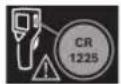
Button cell battery empty Replace the button cell battery (see "Replacing the button cell battery (see picture C)", page 93). Confirm the replacement with "OK" by pressing the center of the multi-function button (17).
Explanation of terms
You can find further information at www.bosch-professional.com/thermal.
Infrared heat radiation
Infrared heat radiation is electromagnetic radiation emitted by any body above 0 Kelvin (-273 °C). The amount of radiation depends on the body's temperature and emissivity.
Emissivity
An object's emissivity depends on the material and the surface structure. It indicates how much infrared heat radiation the object emits compared to an ideal radiator (black body, emissivity ε = 1), and has a value between 0 and 1.
Thermal bridges
Thermal bridges are locations on the exterior of a building where local heat loss occurs due to the building's construction.
Thermal bridges can lead to an increased risk of mold.
Reflected temperature/reflectivity of an object
The reflected temperature is the heat radiation that does not originate from the object itself. Depending on the structure and material, ambient radiation is reflected in the object to be measured, thereby affecting the actual temperature result.
Object distance
The distance between the measuring object and the measuring tool affects the recorded area size per pixel. The greater the object distance, the larger the objects you can detect.
| Afstand (m) Stor infrarød pixel (mm) | Bredde × højde infrarød område (m) |
| 0,30 1,14 ~ 0,29 × 0,22 | |
| 0,55 2,08 ~ 0,53 × 0,40 | |
| 1,00 3,79 ~ 0,97 × 0,73 | |
| 2,00 7,58 ~ 1,94 × 1,46 | |
| 5,00 18,95 ~ 4,85 × 3,64 |
Maintenance and service
Maintenance and cleaning
Store and transport the measuring tool only in a suitable container, such as the original packaging.
Always keep the measuring tool clean. If the infrared sensor (5) is dirty, it can affect measurement accuracy.
When cleaning the measuring tool, ensure that no liquid enters it.
Do not remove dirt from the infrared sensor (5),
the camera (3), the work light (4), or the laser output opening (2) with a pointed object. Do not wipe the infrared sensor or the camera (risk of scratches).
Regularly clean the surfaces at the laser output opening, paying attention to lint.
If you wish to recalibrate the measuring tool, contact an authorized Bosch service center. Send the measuring tool in its original packaging if repair is needed.
The measuring tool contains no user-serviceable parts. Opening the housing parts can damage the measuring tool.
Replacing the button cell battery (see Figure C)
Open the cover (11).
Unscrew the screw (10) from the button cell battery holder. Pull the button cell battery holder (9) out of the measuring tool. Replace the button cell battery. After insertion, retighten the screw (10) on the button cell battery holder.
Customer service and application advice
Customer service answers your questions regarding repair and maintenance of your product as well as spare parts. Spare parts drawings and information about spare parts can also be found at: www.bosch-pt.com
The Bosch customer advice team will be happy to help you if you have questions about our products and accessories.
Always specify the 10-digit product number (see type plate) when making inquiries and ordering spare parts.
Danish
Bosch Service Center
Telegrafvej 3
2750 Ballerup
At www.bosch-pt.dk you can order spare parts online or create a repair order.
Service Center phone: 44898855
Fax: 44898755
E-Mail: vaerktoej@dk.bosch.com
Further service addresses can be found at:
www.bosch-pt.com/serviceaddresses
Transport
The recommended Li-ion batteries comply with the regulations for dangerous goods. The batteries can be transported by the user on public roads without further restrictions.
When shipping via third parties (e.g., air transport or forwarding), special requirements regarding packaging and labeling must be observed. In this case, a dangerous goods expert must be consulted before preparing the shipment.
94 | Swedish
Only send batteries if the housing is undamaged. Tape over open contacts and pack the battery in such a way that it cannot move in the packaging. Any more extensive national regulations must also be observed.
Disposal

Measuring tools, rechargeable batteries, accessories, and packaging must be disposed of in an environmentally correct manner so that they can be recycled.
Do not throw measuring tools and rechargeable batteries into household waste!
Applies only to EU countries:
Used measuring tools and defective or exhausted rechargeable batteries must be disposed of separately. Use the applicable return and collection system.
If the equipment is not disposed of correctly, waste electrical and electronic equipment can damage the environment and harm human health if it contains hazardous substances.
Rechargeable batteries:
Li-ion:
Read and follow the instructions in the transport section (see "Transport", page 93).
Swedish
Safety Instructions

All instructions must be read and followed to ensure risk-free and safe work with the measuring tool. If the measuring tool is not used in accordance with the
instructions provided, the built-in protective mechanisms in the measuring tool may be affected. Keep the warning labels on the measuring tool clearly legible. STORE THESE INSTRUCTIONS IN A SAFE PLACE AND ENSURE THEY ACCOMPANY THE MEASURING TOOL.
- Be careful. If any handling or adjustment devices or methods other than those specified here are used, this may lead to dangerous radiation exposure. The measuring instrument is delivered with a laser warning label (marked on the illustration of the measuring instrument on the graphics page). If the label differs from the language of your country, affix the enclosed sticker in your own language over the laser warning label.
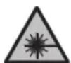
Do not point the laser beam at people or animals, and do not look directly into the direct or reflected laser beam yourself.
This can blind people, cause accidents, or damage the eye.
- If the laser beam hits your eye, close your eyes and turn your head away from the beam. Do not make any modifications to the laser device. Do not use the laser glasses (accessory) as protective goggles. The laser glasses are used to see the laser beam better. They do not protect against laser radiation. Do not use the laser glasses (accessory) as sunglasses or in traffic. The laser glasses do not provide full protection against UV radiation and reduce the ability to perceive colors. Have the measuring tool repaired only by qualified specialists and only with original spare parts. This ensures that the safety of the measuring tool is maintained. Do not let children use the laser measuring tool without supervision. They could accidentally blind themselves or other people. Do not use the measuring tool in explosive environments with flammable liquids, gases, or dust. Sparks are generated in the measuring tool, which can ignite the dust or gases. ▶ The battery must not be opened or modified. This can lead to a short circuit. ▶ In the event of damage or improper use of the battery, vapors may escape. The battery can catch fire or explode. Provide fresh air and consult a doctor if you experience discomfort. The vapors can cause irritation of the respiratory tract. If the battery is used improperly or is damaged, there is a risk of flammable liquid leaking from the battery. Avoid contact with the liquid. In case of accidental contact, rinse with water. If liquid comes into contact with the eyes, also seek medical attention. Battery fluid can cause skin irritation and burns. ▶ The battery can be damaged by sharp objects such as nails or screwdrivers or due to external impact. An internal short circuit can occur, and smoke, explosion, or overheating may occur. Keep paper clips, coins, keys, nails, screws, and other small metal objects away from the unused battery to avoid bridging the contacts. A short circuit of the battery contacts can lead to burns or fire. Use the battery only in products from the manufacturer. This protects the battery from dangerous overload. Charge batteries only in chargers recommended by the manufacturer. If a charger intended for a certain type of battery is used for other battery types, there is a risk of fire.

Protect the battery from high heat, such as prolonged sunlight, fire, dirt, water, and moisture. Risk of explosion and short circuit.
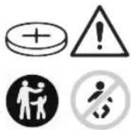
WARNING
Ensure that button cell batteries do not get into the hands of children. Button cell batteries are dangerous.
Button cell batteries must never be swallowed or inserted into other body openings. If you suspect that a button cell battery has been swallowed or inserted into another body opening, seek medical attention immediately. Swallowing a button cell battery can lead to serious internal corrosive injuries and death within 2 hours.
- Be sure to replace the button cell battery correctly. There is a risk of explosion.
Use only the button cells specified in these operating instructions. Do not use any other button cells or other power sources.
Do not attempt to recharge the button cell or short-circuit it. The button cell may leak, explode, burn, and cause personal injury.
Remove and dispose of discharged button cells properly. Discharged button cells may leak and thereby damage the measuring tool or cause personal injury.
- Do not overheat the button cell or throw it into fire. The button cell may leak, explode, burn, and cause personal injury.
- Do not damage the button cell or take it apart. The button cell may leak, explode, burn, and cause personal injury.
A damaged button cell must not come into contact with water. Escaping lithium can generate hydrogen together with water and thereby cause a fire, explosion, or personal injury.
Do not use the measuring instrument if the button cell holder can no longer be closed properly. Remove the button cell and send the measuring instrument in for repair.
High temperature differences in a thermal image can cause even high temperatures to be displayed in a color associated with low temperature. Contact with such a surface can cause burns.
- Correct temperature measurements are only possible if the set emissivity matches the emissivity of the object. Objects can be displayed with too high or too low a temperature, which can lead to danger upon contact.
Do not point the measuring instrument directly at the sun or at a carbon dioxide laser. This can cause damage to the detector.
Protect the measuring instrument, especially the areas around the camera and infrared lens, from moisture, snow, dust, and dirt. The receiver lens can become fogged and give incorrect measurement results. Incorrect settings and other environmental factors can lead to incorrect measurement results. Objects can be displayed with too high or too low a temperature, which can pose a danger upon contact.
Product and performance description
Observe the illustrations at the beginning of the instruction manual.
Intended use
This thermal camera is intended for non-contact measurement of surface temperatures.
The thermal image shows the temperature distribution in the thermal camera's field of view, thus enabling the display of temperature differences in color.
When used correctly, surfaces and objects can be examined without contact for temperature differences and similar, which in turn makes components and/or weak points visible, such as:
- Thermal insulation and insulating materials (e.g., detection of heat leaks),
- Active heating and hot water pipes (e.g., underfloor heating) in floors and walls
- Overheated electrical components (e.g., fuses or terminals)
- Defective or damaged machine parts (e.g., overheating due to defective ball bearings).
The measuring tool is not suitable for temperature measurement of gases.
The measuring tool must not be used for human medical purposes. For veterinary use, see more at www.bosch-professional.com/thermal.
The measuring tool can be used both indoors and outdoors. This is a laser product for private use in accordance with EN 50689.
The measuring tool's lamp is intended to illuminate the immediate work area during image capture and is not a continuous work light.
The laser point must not be used as a laser pointer. It is only for marking the measuring surface.
Depicted components
The numbering of the depicted components refers to the illustration of the measuring tool on the graphics page.
(1) Protective cap (2) Laser beam output opening (3) Visual camera (4) Work light (5) Infrared sensor (6) Pause/start measurement button (7) Battery compartment (8) Laser warning label (9) Button cell holder
(10) Screw for button cell holder
(11) Protection for USB ports and button cell holder
(12) USB Type-C® port a)
(13) Laser button
(14) Battery/battery adapter release button
96 | Swedish
(15) Battery b)
(16) USB Type-C® cable b)
(17) Multifunction button
(18) On/off button/Back button
(19) Display
(20) Serial number
(21) Battery adapter housing
(22) Batteries b)
(23) Battery adapter cover
a) USB Type-C® and USB-C® are trademarks of USB Implementers Forum.
b) Accessories shown and described in the operating instructions are not included in the standard delivery.
Indicators
(a) Emissivity indicator
(b) Reflected temperature indicator
(c) Average temperature indicator
(d) Full memory symbol
(e) Work light symbol
(f) Laser symbol
(g) Charge indicator
(h) Maximum surface temperature indicator in the measuring range
(i) Scale
(j) Minimum surface temperature indicator in the measuring range
(k) Fix temperature scale symbol
(I) Cold spot indicator (example)
(m) Crosshair with temperature indicator
(n) Indication of heat point (example)
(o) Symbol menu
Technical data
| Värmekamera GTC 12V-450-13 | |
| Artikelnummer | 3 601 K83 900 |
| Upplösning infraröd sensor 256 × 192 px | |
| Termisk känslighetA) | ≤ 50 mK |
| Spektralområde 8–14 μm | |
| Siktfält (FOV)A) | 55,6° × 42° |
| Rumslig upplösning (IFOV) 3,79 mrad | |
| FokusavständC) | ≥ 0,5 m |
| Fokus fix | |
| Uppdateringshastighet värmebild ≤ 9 Hz | |
| Mätområde yttemperaturA) | -20 ... +450 °C |
| Mätprecision yttemperaturA)(B)(C) | |
| >0 °C ... ≤ +100 °CD) | ±2 °C |
| >+100 °CE) | ±2 % |
| Temperaturupplösning 0,1 °C | |
| Displaytyp TFT | |
| Displaystorlek 2,8" | |
| Upplösning display 480 × 360 px | |
| Upplösning integrerad visuell kamera 2 MP (640 × 480 px) | |
| Bildformat .jpg | |
| Sparade bilder för varje spara-procedur 1 × värmebild (skärmdump),1 × visuell realbild inkl. temperaturvärden (metadata) | |
| Max. antal bilder i det interna bildminnet 500 | |
| Max. användningshöjd över referenshöjd 2000 m | |
| Nedsmutsningsgrad enligt IEC 61010-1 2 | F) |
| Relativ luftfuktighet max.A) | 90 % |
| Laserklass | 2 |
| Lasertyp | < 1 mW, 645–660 nm |
| Laserstrålens divergens | 1,5 mrad (helvinkel) |
Thermal camera GTC 12V-450-13
| Energiförsörjning | |
| – Batteri (litiumjon) 12 V | |
| – Batterier (alkalisk mangantyp, med batteriadapter) 4 × 1,5 V LR6 (AA) | |
| – Batterier (NiMH, med batteriadapter) 4 × 1,2 V HR6 (AA) | |
| DrifttidG) | |
| – Batteri (litiumjon)H(I) | 8 h |
| – Batterier (alkalisk mangantyp) 4 h | |
| Energiförsörjning systemtid CR1225 (litiumbatteri 3 V) | |
| USB-standard 2.0 | |
| USB-gränssnitt USB Type-C® | |
| ViktI) | 0,354 kg |
| Mätt (längd × bredd × höjd)K) | 89 × 79 × 209 mm |
| Kapslingsklass (utan batterier, i upprätt position) IP54 | |
| Rekommenderad omgivningstemperatur vid laddning 0 °C ... +35 °C | |
| Tillåtna omgivningstemperaturer | |
| – vid användning -10 °C ... +50 °C | |
| – vid lagring med batteri -20 °C ... +50 °C | |
| – vid lagring utan batteri -20 °C ... +70 °C | |
| Rekommenderade batterier GBA 12V... | |
| Rekommenderade laddare GAL 12... | GAX 18... |
A) according to standard VDI 5585 (average value)
B) At an ambient temperature of 20–23 °C and an emissivity of ≥ 0.95, measuring distance: 1 m, operating time: > 5 min, opening of 150 mm, and with work light and laser switched off
C) Plus application-dependent deviation (e.g., reflection, distance, ambient temperature)
D) Applies to the center point, for all other pixels an additional ±1 °C
E) Applies to the center point, for all other pixels an additional ±1 %
F) Only non-conductive dirt occurs, but which due to condensation can become temporarily conductive.
G) With work light switched off and medium display brightness
H) in relation to the battery used
I) At an ambient temperature of 20-30 °C
J) Weight without battery/battery adapter/batteries
K) With GBA 12V 2.0Ah or battery adapter
For unambiguous identification of your measuring tool, the serial number (20) is located on the type plate.
Power supply for measuring tool
The measuring tool can be operated either with a Bosch lithium-ion battery, with conventional batteries, or with NiMH batteries.
Operation with battery (see figure A)
▶ Use only the chargers specified in the technical data.
Only this type of charger is suitable for the lithium-ion battery used in the measuring tool.
Note: Lithium-ion batteries are partially charged according to international transport regulations. For full capacity, charge the battery completely before first use.
To insert the charged battery (15), push it into the battery holder (7) until it clicks into place.
To remove the battery (15), press the release buttons (14) and pull the battery out of the battery compartment (7). Do not use force.
Operation with batteries (see figure B)
Alkaline manganese batteries or NiMH batteries are recommended for the measuring tool.
The batteries are used in the battery adapters.
▶ The battery adapter may only be used with designated Bosch measuring tools and must not be used with power tools.
To insert the batteries, slide the housing (21) of the battery adapter into the battery compartment (7). Place the batteries on the cover (23) in the housing as shown in the figure. Slide the cover over the housing until it audibly clicks into place.
To remove the batteries (22), press the release button (14) on the cover (23) and pull off the cover. Remove the batteries. To remove the inner sleeve (21) from the battery compartment, grasp it and pull it out of the measuring tool with a slight sideways pressure. Always replace all batteries at the same time. Use only batteries with the same capacity and from the same manufacturer.
Remove the batteries from the measuring tool if you do not intend to use it for an extended period. The batteries may corrode if stored for a long time in the measuring tool.
Instructions for correct handling of the battery module
Protect the battery module from moisture and water.
The battery may only be stored within a temperature range between -20 °C and 50 °C. Therefore, do not leave the battery module in the car, for example, in summer.
If the operating time after charging is abnormally short, this indicates that the batteries are exhausted and must be replaced with new ones. Observe the instructions for disposal.
Operation
Protect the measuring tool from moisture and direct sunlight. ▶ Do not expose the measuring tool to extreme temperatures or large temperature fluctuations. Do not leave it in the car, for example, for an extended period. Allow the measuring tool to acclimate after large temperature fluctuations before using it. Extreme temperatures or temperature fluctuations can affect the accuracy of the measuring tool. ▶ Observe correct acclimatization of the measuring tool. With strong temperature variations, the acclimatization time can be up to 60 minutes. This can be the case, for example, if you store the measuring tool in a cold car and then perform a measurement in a warm building. ▶ Avoid subjecting the measuring tool to strong impacts. In the event of strong external influences and if functionality is noticeably affected, the measuring tool must be sent to an authorized Bosch customer service for inspection.
Start-up
At first switch-on
When the measuring tool is switched on for the first time or after a reset to factory settings, a basic setting must be made. Select the desired values by pressing the multifunction button (17) down, up, left, or right. Press the center of the multifunction button (17) to confirm your selection. As soon as you confirm the selection, the next setting appears on the display. The status bar at the top shows the total number of settings and how many remain.
The following basic settings can be made:
Switching on and off
Fold up the protective cap (1) when measuring. During work, ensure that the infrared sensor is not closed or covered.
To switch on the measuring tool, press the on/off button (18). A start sequence is shown on the display (19). After the start sequence, the measuring tool immediately begins measuring and continues continuously until the measuring tool is switched off.
Note: during the first few minutes, the measuring tool may self-calibrate more frequently, as the sensor and ambient temperatures have not yet equalized. Self-calibration provides a more precise measurement.
During this time, the temperature indication may be marked with
~. This effect is intensified by strong variations in ambient temperature. Therefore, switch on the measuring tool a few minutes before starting the measurement to allow the temperature difference to equalize.
To switch off the measuring tool, press the on/off button (18) for more than 1 second. The measuring tool saves all settings and then switches off. Close the protective cap (1) for safe transport of the measuring tool.
In the main menu, you can choose whether and after what time the measuring tool should switch off automatically (see "Main menu", page 100).
If the battery or the measuring tool is outside the operating temperature specified in the technical data, the measuring tool switches off automatically after a brief warning (see "Errors – causes and corrective measures", page 102). Allow the measuring tool to reach normal operating temperature and switch it on again.
Navigating the menus
Navigating the various menus of the measuring tool:
- Display the menu bars: press the center or the left arrow on the multi-function button (17). The menu bars on the right and left are shown on the display, and the main menu is highlighted.
- Scroll through the left menu bar and navigate in the main menu: press the multi-function button (17) up, down, left, or right. – Switch to the left or right menu bar: press the multi-function button (17) left or right.
- Confirm the selection and switch to the submenu: press the center of the multi-function button (17). – Go back from a submenu to a higher-level menu: press the Back button (18).
Measurement preparation
Setting the emissivity for surface temperature measurements
An object's emissivity depends on the material and structure of its surface. It indicates how much infrared heat radiation the object emits relative to a perfect heat radiator (black
body, emissivity ε = 1) and therefore has a value between 0 and 1.
To determine the surface temperature, the natural infrared heat radiation emitted by the target object is measured without contact. For correct measurements, the set emissivity must be checked before each measurement and adjusted to the measuring object if necessary.
The emissivities preset in the measuring instrument are reference values.
You can select one of the preset emissivities or enter a more precise value. Set the desired emissivity via the menu → (see "Main menu", page 100).
- Correct temperature measurements are only possible if the set emissivity matches the object's emissivity.
The lower the emissivity, the greater the influence of the reflected temperature on the measurement result. Therefore, always adjust the reflected temperature when changing the emissivity. Set the reflected temperature via the menu
→ (see "Main menu", page 100).
Incorrect temperature differences displayed on the measuring instrument can be due to different temperatures and/or different emissivities. With strongly varying emissivities, displayed temperature differences can deviate significantly from the actual temperature differences.
If there are multiple measuring objects of different materials or with different structures in the measuring area, the displayed temperature is accurate only for those objects for which the emissivity is set. For other objects (with different emissivity), the displayed color differences can be used as a reference for temperature conditions.
Instructions for measurement conditions
Highly reflective or shiny surfaces (e.g., shiny tiles or polished metal) can significantly affect the result. If necessary, tape the measuring surface with a dark, matte tape that conducts heat well. Allow the tape to briefly acclimate to the surface temperature.
Ensure a good measuring angle on reflective surfaces so that reflected heat radiation from other objects does not cause incorrect results. For example, reflection of your body heat can affect the measurement when measuring perpendicularly from the front. On a smooth surface, the contours and temperature of your body may be displayed (reflected value), which does not correspond to the actual surface temperature (calculated or actual value).
Measurement through transparent materials (e.g., glass or transparent plastics) is generally not possible.
The measurement results become more accurate and reliable the better and more stable the measurement conditions are. Not only strong temperature fluctuations in the environment are relevant, but also strong variations in the temperature of the measured object.
Infrared temperature measurement is affected by smoke, steam/high humidity, and dust in the air.
Instructions for measurements with better precision:
- Get as close to the measuring instrument as possible to minimize interfering factors between you and the measuring surface.
- Ventilate the area before measuring, especially if the air is dirty or humid. After ventilating, let the room temperature stabilize until it returns to normal.
Marking the measuring point
Never point the laser beam at people or animals, and do not look directly into the laser beam yourself, even from a distance.
The measuring instrument is equipped with a laser to mark the measuring point.
Press and hold the laser button (13).
The laser icon (f) appears in the status bar, and a red circle is shown around the crosshair (m). The laser and crosshair overlap exactly at a distance of 1 m. When you release the laser button (13), the laser turns off.
Temperature scale division
On the right side of the display, the scale (i) is shown. The values at the top and bottom ends represent the highest temperature (h) and lowest temperature (j) present in the thermal image. For the scale, 99.99% of all pixels are considered. The assignment of a color to a temperature value in the image is distributed evenly (linearly).
Using different shades, the temperature can be ordered within these two limit values. A temperature that lies exactly between the maximum and minimum value is thus assigned, for example, the middle color range of the scale.
For temperature calculation of a specific area, move the measuring instrument so that the crosshair with temperature indication (m) is aimed at the desired point/area. With automatic adjustment, the scale's color spectrum is always distributed linearly (= evenly) over the entire area within the temperature range.
The measuring instrument displays all measured temperatures within the measuring range in relation to each other. If the heat in the color palette is shown as bluish in an area, for example in color rendering, it means that the bluish areas belong to the colder measured values in the current measuring range. However, these areas can lie within a temperature range that under certain circumstances can cause damage. Therefore, always observe the displayed temperatures on the scale or directly on the crosshair.
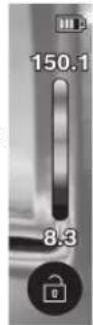
Functions
Observe the information on how to navigate the various menus (see "Navigating the menus", page 98)

Illuminating the measuring object
The measuring tool is equipped with a work light (4). It is intended to illuminate the immediate work area when taking images and is not a continuous work light.
Go to the left sidebar to turn the work light on/off. Scroll to the menu item /<LED lamp
off> and confirm your selection. When the work light is switched on, this is shown in the status bar.
The light switches off automatically after 2 minutes to avoid affecting the accuracy of the measurement.
You can determine the automatic switch-off time in the menu under .
Overlap of thermal and real image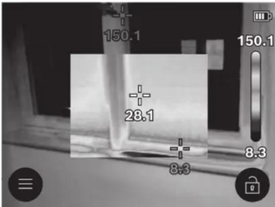
For better orientation (= spatial assignment of the displayed thermal image), a visual real image can be linked if the temperature ranges are balanced.
Note: the overlap of the real and thermal image is exact at a distance of 1 m. If the distance to the measuring object differs, there is a shift between the real image and the thermal image. This shift can be compensated for with special Bosch functions. Information about the functions and their compatibility can be found on the measuring tool's product page or at www.bosch-professional.com/thermal.
The measuring tool offers you the following options:
- 100% infrared image
Only the thermal image is displayed.

- Transparency
The displayed thermal image is overlaid transparently on the real image. This makes objects clearer.
To activate/deactivate the setting, go to the sidebar and scroll to the menu item / . Confirm your selection by pressing the center of the multi-function button (17).

- Picture in picture
The thermal image shown will be cropped and the area around it will be displayed as a real image. This setting improves the spatial assignment of the measurement area.
To activate/deactivate the setting, go to the sidebar and scroll to the menu item / . Confirm your selection by pressing the center of the multi-function button (17).
Adjusting color rendering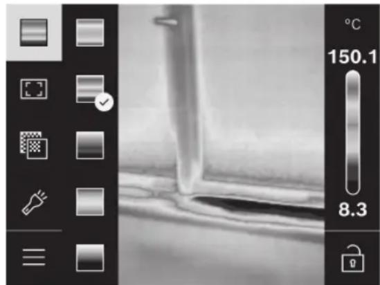
Depending on the measurement situation, different color palettes can facilitate the analysis of the thermal image and depict objects or conditions more clearly on the display. The measured temperatures are not affected by this. Only the representation of the temperature values changes.
To switch the color palette, open the sidebar and scroll to the menu item "Color palette". Confirm your selection by pressing the center of the multi-function button (17).

Fix the scale
The adjustment of the color distribution in the thermal image occurs automatically, but you can fix it by pressing the right arrow of the multi-function button (17) and then its center. This enables comparison between thermal images taken under different temperature conditions (e.g., when checking multiple rooms for heat leaks) or masking a very cold or hot object in the thermal image that would otherwise distort it (e.g., a radiator as a hot object when searching for heat leaks).
To return to the automatic color scale, go to the right sidebar and press the center of the multi-function button (17). The temperatures now relate dynamically again and adapt to the measured min and max values.
Main menu
Go to the left sidebar (see "Navigating in the various menus", page 98). To open the main menu, press the center of the multi-function button (17).
- Under this menu item, you can delete individual saved images or all at once.
- (a)
Saved emissivity values are available for some of the most common materials. To facilitate the search, the values are summarized in groups in the emissivity catalog. Select the appropriate category under the menu item and then the suitable material. If you know the measurement object's
exact emissivity, you can set it under the menu item .
• (b)
Adjusting this parameter can improve the measurement result, especially for materials with low emissivity (= high reflection). In some situations (particularly indoors), the reflected temperature corresponds to the ambient temperature. If objects with significantly different temperatures near the reflecting object can affect the measurement, adjust this value. Press left or right on the multi-function button (17).
-
To ensure high accuracy over the entire measuring range, the measurement is performed in two temperature ranges. In the measurement function, the instrument selects the appropriate temperature range based on the temperature distribution in the thermal image. An evaluation is performed to determine how many measured values lie above a certain temperature threshold. If very small and hot objects are to be measured, a low temperature range that is not suitable for high temperatures may occur. This is indicated by the symbol \~ displayed in front of the temperature indication. In this case, switch to the measurement function <100 °C ... 450 °C> or <-20 °C ... 100 °C>, where the color distribution corresponds to the set temperature range. The setting is marked on the scale with an up or down arrow.
-
- (m): /
The point is displayed in the center of the thermal image and shows the measured temperature value at that location.
• (n): /
The hottest point (= measurement pixel) is marked with a red crosshair in the thermal image. This facilitates the search for critical spots (e.g., loose terminal clamps in a switch cabinet).
- (I): /
The coldest point (= measurement pixel) is marked with a blue crosshair in the thermal image. This facilitates the search for critical spots (e.g., leaks in a window).
• (i): /
• (c): /
The average temperature (c) is displayed at the top left of the thermal image (average temperature of all measured values in the thermal image). This can make it easier to determine the reflected temperature.
-
•
Under this menu option, you can adjust the brightness of the display backlight.
-
Under this menu option, you can select the time interval for the automatic shutdown of the work lamp when no button is pressed.
-
Under this menu option, you can select the time interval after which the measuring instrument will shut down
automatically if no button is pressed. You can also deactivate the automatic shutdown by selecting the setting .
-
In this submenu, in addition to setting the date and time, you can also change their format.
-
Under this menu option, you can select the language used.
-
Under this menu item, you can reset the measuring instrument to factory settings and permanently delete all data. This may in some cases take several minutes. Press the right arrow on the multifunction button (17) to delete all files, or the left arrow on the multifunction button (17) to cancel.
-
Under this menu option, you can open information about the measuring instrument. There you will find the instrument's serial number and installed software version.
In addition, there is further information about the measuring instrument and about updating the software.
To exit any menu and return to the standard screen, you can also press the Measurement button (6).
Updating measuring instrument software
If necessary, you can update the measuring instrument's software via the USB Type-C® interface. More information about this can be found at:
www.bosch-professional.com/thermal-update.
Documentation of measurement results
Saving measurement results
Immediately after starting, the measuring instrument begins measuring and continues continuously until the instrument is switched off.
To save an image, aim the camera at the desired measuring object and press the Measurement button (6). The image is saved in the instrument's internal memory. The measurement is frozen and displayed on the screen. This allows you to review the image in detail and adjust it afterwards (e.g., the color palette). If you do not want to save the frozen image, start the measuring mode again with the Measurement button (6). If you want to save the image in the instrument's internal memory, press the multifunction button (17).
Opening saved images
To open saved thermal images, do the following:
- Immediately after saving, press the center of the multifunction button (17) once more. A thumbnail of the last saved photo is now displayed on the screen.
- You can also access the saved photos under the menu item .
- To switch between saved thermal images, press right or left on the multifunction button (17).
In addition to the thermal image, the visual image is also saved. To access it, press up or down on the multifunction button (17).
After 5 seconds, the measuring tool switches to full-screen mode. In full-screen mode, the header row is hidden so you can review all details of the thermal image.
You can switch between modes by pressing up and down on the multi-function button (17).
Delete saved images
Press the center of the multi-function button (17) to delete individual or all thermal images. A submenu opens.
- Here you can choose whether to delete only this image or all images. Confirm your selection by pressing the center of the multi-function button (17).
For the option, you can choose between and . Confirm your selection by pressing the center of the multi-function button (17).
- In this submenu, you can also review information about emissivity and reflected temperature.
The image data fragments remain in memory and the images can be reconstructed. For permanent deletion, select
→ in the main menu.
Data transfer
Data transfer via USB port
Open the cover (11) over the USB Type-C® port. Connect the USB Type-C® port (12) on the measuring tool to your computer using the included USB Type-C® cable (16).
Turn on the measuring tool with the on/off button (18).
Open the file manager on your computer and select the drive GTC_450. Saved data can be copied, moved to your computer, or deleted from the internal memory of the measuring tool. Once you have completed the desired action, disconnect the measuring tool from the computer and turn it off with the on/off button (18).
Note: first eject the device from your operating system, otherwise the internal memory of the measuring tool may be damaged.
Remove the USB Type-C® cable and close the cover (11).
Always keep the cover over the USB port closed so that dust and water cannot enter the housing.
Note: Only connect the measuring instrument to a computer via USB. Connecting to other devices may damage the measuring instrument.
Note: The USB Type-C® port is only for data transfer. Batteries must not be charged via this port.
Post-processing of thermal images
You can edit the saved thermal images with special Bosch functions. Information about the functions and their compatibility can be found on the product page of the measuring instrument or at www.bosch-professional.com/thermal.
Errors – causes and corrective measures
In the event of a malfunction, the measuring instrument restarts and can then be used again. If error messages persist, you can use the overview below.
Error Cause Corrective measure
| Mätinstrumentet kan inte startas. | Uppladdningsbart batteri/engångsbatterier urladdade | Ladda det uppladdningsbara batteriet eller byt ut engångsbatterierna. | |
 | Batterifel Byt ut det uppladdningsbara batteriet/engångsbatterierna. | ||
 | För hög eller för låg temperatur i det uppladdningsbara batteriet/engångsbatterierna | Låt temperaturen i det uppladdningsbara batteriet utjämnas eller byt ut detta resp. engångsbatterierna. | |
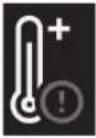 | Mätinstrumentet är för varmt eller för kallt | Låt mätinstrumentets temperatur utjämnas. | |
 | USB-anslutning eller USB-kabel defekt | Kontrollera om mätinstrumentet kan anslutas till en annan dator. Om inte, skicka mätinstrumentet till en auktoriserad Bosch-kundtjänst.Anmärkning: Använd endast den USB-kabel som medföljer. | |
| Mätinstrumentet kan inte anslutas till en dator. | |||
Error Cause Corrective measure
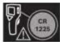
Button cell battery discharged Replace the button cell battery (see "Replacing the button cell battery"
(see figure C), page 103). Confirm your selection with "OK" by pressing the center of the multi-function button (17).
Definitions
More information on this can be found at www.bosch-professional.com/thermal.
Infrared thermal radiation
Infrared heat radiation is electromagnetic radiation emitted by all bodies above 0 Kelvin (-273 °C). The amount of radiation depends on temperature and the emissivity of the body.
Emissivity
An object's emissivity depends on the material and structure of its surface. It indicates how much infrared heat radiation the object emits relative to a perfect radiator (black body, emissivity ε = 1) and therefore has a value between 0 and 1.
Heat leak
A heat leak is a location in the building's exterior wall where a local heat loss has occurred due to the construction. Heat leaks can lead to an increased risk of mold.
Reflected temperature of an object
The reflected temperature is the heat radiation that does not originate from the object itself. Depending on structure and material, radiation from the surroundings is reflected in the object to be measured and thus falsifies the actual temperature result.
Object distance
The distance between the measuring object and the measuring instrument affects the registered surface size per pixel. With increasing object distance, you can register larger objects.
| Avstånd (m) Storlek infrarödpixlar (mm) | Bredd × höjd infrarött område (m) |
| 0,30 1,14 ~ 0,29 × 0,22 | |
| 0,55 2,08 ~ 0,53 × 0,40 | |
| 1,00 3,79 ~ 0,97 × 0,73 | |
| 2,00 7,58 ~ 1,94 × 1,46 | |
| 5,00 18,95 ~ 4,85 × 3,64 |
Maintenance and service
Maintenance and cleaning
Store and transport the measuring instrument only in a suitable container, such as the original packaging.
Always keep the measuring instrument clean. A dirty infrared sensor (5) can affect measurement accuracy.
When cleaning, liquid must not penetrate into the measuring tool.
Do not attempt to remove dirt from the IR sensor (5), camera (3), work light (4), or laser output opening (2) with pointed objects. Do not wipe the infrared sensor and camera (risk of scratches).
Clean the surfaces around the laser's exit opening regularly and remove any dust.
If you want to recalibrate your measuring tool, contact an authorized Bosch customer service.
Send the measuring tool in its original packaging for repair.
There are no parts inside the measuring tool that can be serviced by the user. The measuring tool can be damaged if the cover is opened.
Replacing the button cell battery (see figure C)
Open the cover (11).
Unscrew the screw (10) from the button cell holder. Pull the button cell holder (9) out of the measuring tool. Replace the button cell battery. Tighten the screw (10) again after inserting the button cell holder.
Customer service and application advice
Customer service provides answers to questions regarding repair and maintenance of products and spare parts. Exploded views and information on spare parts are also available at:
www.bosch-pt.com
The Bosch advisory team will be happy to help you if you have questions about our products and accessories.
Always specify the 10-digit product number found on the product's rating plate when making inquiries and ordering spare parts.
Swedish
Bosch Service Center
Telegrafvej 3
2750 Ballerup
Denmark
Tel.: (08) 7501820 (within Sweden)
Fax: (011) 187691
Further service addresses can be found at:
www.bosch-pt.com/serviceaddresses
Transport
The recommended lithium-ion batteries are subject to the requirements for dangerous goods. The user can transport the batteries on public roads without further obligations.
When transporting by a third party (e.g., air freight or forwarding), special conditions for packaging and labeling must be observed. In this case, an expert for dangerous goods should be consulted when preparing the transport.
Secondary batteries may only be shipped if the housing is undamaged. Tape open contacts and pack the battery so that
104 | Norwegian
it cannot move in the packaging. Also observe any national regulations.
Disposal

Measuring tools, batteries, accessories, and packaging should be disposed of in an environmentally friendly manner for recycling.
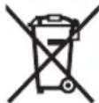
Do not throw measuring tools and batteries into household waste!
Only for EU countries:
Used measuring instruments and defective or used batteries must be disposed of separately. Take them to a recycling center.
In the event of improper disposal, electrical and electronic waste equipment may have a harmful effect on the environment and human health due to potentially hazardous substances.
Batteries:
Li-ion:
Observe the instructions in the Transport section (see "Transport", page 103).
Norwegian
Safety instructions

All instructions must be read and followed to ensure the measuring tool can be used safely and without danger. If the measuring tool is not used in accordance with the provided instructions, the integrated protective devices may be damaged. Warning signs on the measuring tool must always be visible and legible. KEEP THESE INSTRUCTIONS IN A SAFE PLACE AND PASS THEM ON IF THE MEASURING TOOL IS USED BY OTHERS.
Caution! Use of operating or adjustment devices other than those specified here, or other procedures, may result in hazardous radiation exposure. The measuring tool is supplied with a laser warning sign (marked on the illustration page). If the text on the laser warning sign is not in your language, affix a label in your language over the sign before putting the product into operation.
Never point the laser beam at people or animals, and do not look directly into the laser beam,
or the reflected laser beam. This can cause glare, accidents, and eye damage.
▶ If eye contact is made with the laser beam, deliberately close the eye and immediately move the head away from the beam. Do not make any modifications to the laser equipment. ▶ Do not use the laser viewing glasses (accessory) as protective goggles. The laser glasses make it easier to see the laser beam, but they do not protect against laser radiation. ▶ Do not use the laser viewing glasses (accessory) as sunglasses or while driving. The laser glasses do not provide full UV protection and impair color perception. ▶ Repairs to the measuring tool must only be carried out by qualified specialists and only with original spare parts. This maintains the safety of the measuring tool. Do not allow children to use the laser measurer without supervision. They could inadvertently blind themselves or others. Do not work with the measuring tool in explosive atmospheres – where flammable liquids, gases, or dust are present. Sparks may be generated in the measuring tool that could ignite dust or vapors. ▶ Do not modify or open the battery. There is a risk of short circuit. Damaged or improperly used batteries may emit vapors. The battery can burn or explode. Ensure fresh air supply and seek medical attention if you experience discomfort. The vapors can irritate the respiratory system. In case of misuse or a damaged battery, flammable liquid may leak from the battery. Avoid contact with the liquid. In case of accidental contact, rinse with water. If liquid gets into the eyes, also seek medical attention. Battery fluid that leaks out can cause skin irritation or burns. ▶ The battery can be damaged by sharp objects such as nails or screwdrivers or due to external impact. This can result in an internal short circuit, and the battery may emit smoke, catch fire, explode, or overheat. When the battery is not in use, keep it at a distance from paper clips, coins, keys, nails, screws, or other small metal objects that could create a connection between the contacts. A short circuit between the battery contacts can lead to burns or fire. ▶ The battery must only be used in products from the manufacturer. Only this way is the battery protected against dangerous overload. Charge the batteries only with chargers recommended by the manufacturer. Using a charger suitable for one type of battery with other batteries poses a fire hazard.

Protect the battery from heat, e.g., also from prolonged sunlight and fire, dirt, water, and moisture. There is a risk of explosion and short circuit.
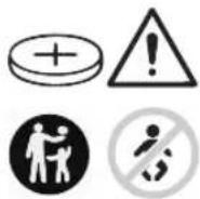
WARNING
Ensure that the button cell battery is not accessible to children. Button cell batteries are dangerous.
Button cell batteries must never be swallowed or inserted into other body openings. If you suspect that a button cell battery has been swallowed or inserted into another body opening, seek medical attention immediately. Swallowing a button cell battery can cause severe internal burns and death within 2 hours.
▶ Ensure that the button cell battery is replaced correctly. There is a risk of explosion.
▶ Use only the button cells specified in these operating instructions. Do not use any other button cells or any other power supply.
Do not attempt to recharge the button cell battery or short-circuit it. The button cell battery may leak, explode, burn, and cause personal injury.
▶ Remove discharged button cell batteries and dispose of them properly. Discharged button cell batteries may leak and thereby damage the product or cause personal injury.
The button cell battery must not be overheated or thrown into open fire. The button cell battery may leak, explode, burn, and cause personal injury.
Do not damage the button cell battery or take it apart. The button cell battery may leak, explode, burn, and cause personal injury.
A damaged button cell battery must not come into contact with water. Leaking lithium and water can form hydrogen and thereby lead to fire, explosion, or personal injury.
▶ Do not use the measuring tool if the battery compartment cover can no longer be closed properly and completely. Remove the button cell battery and have the measuring tool repaired.
Large temperature differences in a thermal image can cause high temperatures to be displayed with a color associated with low temperatures. Touching such a surface can lead to burns.
Correct temperature measurement is only possible if the set emissivity and the emissivity of the object match. Objects may be displayed with too high or too low a temperature, which can lead to danger when touched.
Never point the measuring tool directly at the sun or at CO₂ high-performance lasers. This can cause damage to the detector.
▶ Protect the measuring tool, especially the areas around the camera and the infrared lens, from moisture, snow, dust, and dirt. The receiver lens can become fogged or dirty, causing incorrect measurement results. Incorrect instrument settings and other atmospheric conditions can lead to measurement errors. Objects may be displayed with too high
or too low a temperature, which can lead to danger when touched.
Product Description and Performance Specifications
Pay attention to the illustrations in the front part of the operating instructions.
Intended Use
This thermal camera is intended for non-contact measurement of surface temperatures.
The displayed thermal image illustrates the temperature distribution in the thermal camera's field of view and thus provides the ability to visualize temperature deviations with different colors.
With proper use, surfaces and objects can be examined non-contact for temperature differences and deviations, allowing you to locate components and/or potential weak points, e.g.:
- thermal insulation (e.g., detection of thermal bridges),
- active heating and hot water pipes (e.g., underfloor heating) in floors and walls,
- overheated electrical components (e.g., fuses or terminals),
- defective or damaged machine parts (e.g., overheating due to defective ball bearings).
The measuring tool is not suitable for temperature measurement on gases. The measuring tool must not be used for medical purposes on humans.
See www.bosch-professional.com/thermal for information on use for veterinary medical purposes.
The measuring tool is suitable for indoor and outdoor use.
This product is a laser product for consumers in accordance with EN 50689.
The light of the measuring tool is intended for illuminating the immediate work area of the measuring tool for image capture and serves as a permanent work light.
The laser point must not be used as a laser pointer. It serves exclusively to mark the measuring surface.
Illustrated components
The numbering of the illustrated components refers to the image of the measuring tool on the illustration page.
(1) Protective cap
(2) Laser opening
(3) Visual camera
(4) Work light
(5) IR sensor
(6) Pause/start measurement button
(7) Battery compartment
(8) Laser warning label
(9) Holder for coin cell battery
106 | English
(10) Screw for coin cell battery holder
(11) Cover for USB connector and coin cell battery holder
(12) USB Type-C ® plug a)
(13) Laser button
(14) Battery/battery adapter release button
(15) Rechargeable battery b)
(16) USB Type-C® cable b)
(17) Multifunction button
(18) On/off button/Back button
(19) Display
(20) Serial number
(21) Battery adapter holster
(22) Batteries b)
(23) Battery adapter cover
a) USB Type-C® and USB-C® are trademarks of USB Implementers Forum.
b) Illustrated or described accessories are not included in the standard delivery.
Display elements
(a) Emission factor indicator (b) Reflected temperature indicator (c) Average temperature indicator (d) Full storage space symbol (e) Work light symbol (f) Laser symbol (g) Charge level indicator (h) Maximum surface temperature indicator in the measuring range (i) Scale (j) Minimum surface temperature indicator in the measuring range (k) Temperature scale lock symbol (I) Cold spot indicator (example)
(m) Crosshair with temperature display
(n) Overheated spot indicator (example)
(o) Symbol for many
Technical data
| Termisk kamera GTC 12V-450-13 | |
| Artikkelnummer | 3 601 K83 900 |
| IR-sensorens oppløsning 256 × 192 px | |
| Termisk følsomhetA) | ≤ 50 mK |
| Spektralområde 8-14 μm | |
| Synsfelt (FOV)A) | 55,6° × 42° |
| Romoppløsning (IFOV) 3,79 mrad | |
| FokusavstandA) | ≥ 0,5 m |
| Fokus fast | |
| Bilderepetisjonsfrekvens varmebilde ≤ 9 Hz | |
| Måleområde overflatetemperaturA) | -20 ... +450 °C |
| Målenøyaktighet overflatetemperaturA)(B)(C) | |
| >0 °C ... ≤ +100 °CD) | ±2 °C |
| >+100 °CE) | ±2 % |
| Temperaturoppløsning 0,1 °C | |
| Displaytype TFT | |
| Displaystørrelse 2,8" | |
| Oppløsning display 480 × 360 px | |
| Oppløsning integrert visuelt kamera 2 MP (640 × 480 px) | |
| Bildeformat .jpg | |
| Lagrede elementer per lagringsprosess 1 × varmebilde (skjermbilde), | 1 × vanlig bilde inkl. temperaturverdier (metadata) |
| Maks. antall bilder i internt bildeminne 500 | |
| Maks. brukshøyde over referansehøyde 2000 m | |
| Forurensningsgrad i henhold til IEC 61010-1 2 | F) |
| Relativ luftfuktighet maks.A) | 90 % |
Thermal camera GTC 12V-450-13
| Laserklasse 2 | |
| Lasertype < 1 mW, 645–660 nm | |
| Laserstrålens divergens 1,5 mrad (360-graders vinkel) | |
| Strømforsyning | |
| - Oppladbart batteri (li-ion) 12 V | |
| - Batterier (alkaliske/mangan med batteriadapter) 4 × 1,5 V LR6 (AA) | |
| - Batterier (NiMH med batteriadapter) 4 × 1,2 V HR6 (AA) | |
| Brukstid G) | |
| - Oppladbart batteri (li-ion) H) | 8 t |
| - Batterier (alkali-mangan) 4 t | |
| Strømforsyning systemtid CR1225 (3 V litiumbatteri) | |
| USB-standard 2.0 | |
| USB-grensesnitt USB Type-C® | |
| Vekt J) | 0,354 kg |
| Mål (lengde × bredde × høyde) K) | 89 × 79 × 209 mm |
| Kapslingsgrad (unntatt batterier, i oppreist posisjon) IP54 | |
| Anbefalt omgivelsestemperatur ved lading 0 °C ... +35 °C | |
| Tillatt omgivelsestemperatur | |
| - under drift -10 °C ... +50 °C | |
| - ved lagring med batteri -20 °C ... +50 °C | |
| - ved lagring uten batteri -20 °C ... +70 °C | |
| Anbefalte batterier GBA 12V... | |
| Anbefalte ladere | GAL 12...GAX 18... |
A) According to standard VDI 5585 (average value) B) At ambient temperature of 20–23 °C and emissivity factor ≥ 0.95, measuring distance: 1 m, operating time: > 5 min, aperture of 150 mm, with work light and laser switched off C) In addition to use-dependent deviation (e.g., reflection, distance, ambient temperature) D) Applies to the center point, for all other pixels additionally ±1 °C E) Applies to the center point, for all other pixels additionally ±1 % F) Only non-conductive dirt occurs, but occasional transient conductivity caused by condensation is expected. G) With work light switched off and medium screen brightness H) Depending on the battery used I) At ambient temperature of 20-30 °C J) Weight without rechargeable battery/battery adapter/disposable batteries K) With GBA 12V 2.0Ah or battery adapter The serial number (20) on the type plate uniquely identifies the measuring tool.
Power supply for the measuring tool
The measuring tool can be operated with a Bosch Li-ion battery or with standard rechargeable NiMH batteries.
Operation with rechargeable battery (see figure A)
▶ Use only the chargers listed in the technical data. Only these chargers are compatible with the Li-ion batteries that can be used in the power tool.
Note: In accordance with international transport regulations, lithium-ion batteries are delivered partially charged. To ensure full
battery performance, charge it completely before first use.
To insert the charged battery (15), push it into the battery compartment (7) until it clicks into place.
To remove the battery (15), press the release buttons (14) and pull the battery out of the compartment (7). Do not use force.
Operation with disposable batteries (see figure B)
Alkaline manganese batteries or NiMH batteries are recommended for operating the measuring tool.
108 | Norwegian
Insert the batteries into the battery adapter.
▶ The battery adapter is intended exclusively for use with the specified Bosch measuring tools and must not be used with power tools.
To insert the batteries, push the sleeve (21) of the battery adapter into the battery compartment (7). Place the batteries in the sleeve (23) as shown in the illustration on the cover. Slide the cover over the sleeve until it clicks into place.
To remove the batteries (22), press the release buttons (14) on the cover (23) and pull off the cover. Remove the batteries. To remove the sleeve (21) from the inside of the battery compartment, grasp the sleeve and pull it out of the measuring tool with a slight pressure against the side wall. Always replace all rechargeable batteries or all disposable batteries at the same time. Use only batteries from one manufacturer and with the same capacity.
Remove the batteries, whether disposable or rechargeable, from the measuring tool if you are not going to use it for an extended period. Batteries, both disposable and rechargeable, can corrode if stored for a long time in the measuring tool.
Rules for optimal use of rechargeable batteries
Protect the battery from moisture and water.
The battery must be stored at temperatures between -20 °C and 50 °C.
For example, do not leave it in the car in summer.
A significantly shorter operating time after charging is a sign that the battery is worn out and must be replaced.
Follow the disposal instructions.
Operation
▶ Protect the measuring tool from moisture and direct sunlight. Do not expose the measuring tool to extreme temperatures or temperature fluctuations. For example, do not leave it in the car for a long time. In case of large temperature fluctuations, the measuring tool should be allowed to acclimate before use. Extreme temperatures or temperature fluctuations can impair the measuring tool's accuracy. ▶ Ensure proper acclimatization of the measuring tool. In case of large temperature fluctuations, acclimatization can take up to 60 minutes. This can be the case, for example, if you store the measuring tool in a cold car and then take a measurement in a warm building. ▶ Avoid strong impacts to the measuring tool or dropping it. If the measuring tool has been subjected to strong external influence or does not function properly, have it inspected at an authorized Bosch service center.
Start-up
When switching on for the first time
When you switch on the measuring tool for the first time or after resetting it to factory settings, you must make some basic settings. Select the desired values by pressing the multi-function button (17) down, up, left, or right. Press the multi-function button (17) in the center to confirm your selection. As soon as you have confirmed the selection, the next setting appears on the display. The total number and the number of remaining settings are shown in the status bar at the top.
These basic settings are available:
-
Switching on/off
Fold up the protective cap (1) when you want to measure. During work, make sure that the IR sensor is not covered or hidden.
To switch on the measuring tool, press the on/off button (18). A start sequence appears on the display (19). After the start sequence, the measuring tool immediately begins to measure, and it continues measuring continuously until the tool is switched off.
Note: During the first few minutes, the measuring tool may adjust itself automatically several times, as the sensor and ambient temperatures have not yet adapted to each other. This new sensor adjustment enables accurate measurement.
During this period, the temperature display may be marked with \~. This effect is intensified by large variations in the ambient temperature. If possible, switch on the measuring tool a few minutes before you begin measuring so that the temperature stabilizes.
To switch off the measuring tool, press the on/off button (18) for > 1 s. The measuring tool saves all settings and switches off. For safe transport of the measuring tool, close the protective cap (1).
In the main menu, you can select whether and after how long the measuring tool should switch off automatically (see "Main menu", Page 111).
If the temperature of the battery or the measuring tool does not comply with the operating temperature specified in the technical specifications, the measuring tool switches off automatically after a brief warning (see "Errors – Cause and remedy", Page 112). Allow the measuring tool to reach operating temperature and switch it on again.
Navigating in the various menus
Navigating in the various menus of the measuring tool:
– Go to the menu lines: Press the multi-function button (17) in the center or to the left. The menu lines to the right and left are shown on the display; the main menu is highlighted.
- Scroll in the menu line to the left/navigate in the main menu: Press the multi-function button (17) up, down, left, or right.
- Switch to the left or right menu line: Press the multifunction button (17) to the left or right.
- Confirm the selection/switch to the submenu: Press the multifunction button (17) in the middle.
Switch back from a submenu to a higher menu: Press the Back button (18).
Preparation for measurement
Setting the emission factor for surface temperature measurements
An object's emission factor depends on the material and surface structure. It indicates how much IR heat radiation the object emits compared to an ideal heat radiator (black body, emission factor ε = 1) and therefore has a value between 0 and 1.
When determining surface temperature, the natural IR heat radiation from the measuring object is measured contactlessly. For correct measurement, the emission factor set on the measuring tool must be checked and, if necessary, adjusted to the measuring object before each measurement.
The emission factors set on the measuring tool are for guidance only.
You can select one of the preset emission factors or enter an exact value. Set the desired emission factor via the menu → (see "Main menu", page 111).
Correct temperature measurement requires that the set emission factor and the object's emission factor match.
The lower the emission factor, the greater the influence on the reflected measurement result. Therefore, always adjust the reflected temperature when changing the emission factor. Set the reflected temperature via the menu
→ (see "Main menu", page 111).
Assumed temperature differences displayed by the measuring tool can be due to different temperatures and/or different emission factors. With very different emission factors, the displayed temperature differences may deviate noticeably from the actual ones.
If there are multiple measuring objects with different materials or different structures in the measuring range, the displayed temperature values are only accurate for the objects that match the set emission factor. For all other objects (with a different emission factor), the displayed color differences can be used as an indication of temperature conditions.
Information on measurement conditions
Strongly reflective or glossy surfaces (e.g., glossy tiles or polished metals) can significantly affect the displayed results or lead to incorrect readings. If necessary, mask the measuring surface with a dark, matte tape that has good thermal conductivity. Allow the tape to briefly absorb the surface temperature.
When dealing with reflective surfaces, ensure that the measuring angle is favorable so that reflected thermal radiation from other objects does not affect the result. For example, when measuring vertically from the front, your body heat can influence the measurement. On flat surfaces, the contours and temperature of your body may be displayed (reflected value), which do not correspond to the actual
temperature of the measured surface (the emissivity value or the actual surface value).
Measurement through transparent materials (e.g., glass or transparent plastic) is not possible due to the operating principle.
The measurement results become more accurate and reliable the better and more stable the measurement conditions are. Not only large fluctuations in ambient conditions are relevant, but also large variations in the temperature of the measured object can affect accuracy.
IR temperature measurement is affected by smoke, steam/high humidity, or dusty air.
Tips for more accurate measurements:
- Stand as close to the measuring object as possible to minimize disturbances between you and the measuring surface.
- Ventilate indoor spaces before measuring, especially if the air is dirty or very humid. After ventilating the room, allow it to cool down until it returns to normal temperature.
Marking the measuring point
Never point the laser beam at people or animals, and do not look into the laser beam yourself, even from a distance.
The measuring tool is equipped with a laser to mark the measuring point.
Press and hold the laser button (13). The laser symbol (f) appears in the status bar, and a red circle appears around the crosshair (m). When the laser and crosshair are superimposed, they align exactly at a distance of 1 m. When you release the laser button (13), the laser turns off.
Assigning temperatures using the scale
On the right side of the display, the scale (i) is shown. The values at the top and bottom are based on the maximum (h) and minimum (j) temperatures recorded in the thermal image. For the scale, 99.99% of the total pixels are considered. A color is assigned to a temperature value in the image using a uniform (linear) distribution.
Using the different color shades, temperatures can thus be assigned within these two limit values. A temperature that is exactly between the maximum and minimum value is assigned, for example, to the middle color range of the scale.
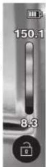
To determine the temperature of a specific area, move the measuring tool so that the crosshair with the temperature display (m) is aimed at the desired point or area. In the automatic setting, the scale's color spectrum is always distributed linearly (= evenly) within the maximum and minimum temperature across the entire measuring range.
The measuring tool displays all measured temperatures in the measuring range in relation to each other. If heat is shown as bluish in the color palette on an area, for example in a graphic with colors, this means that the bluish areas belong to the colder measured values in the current measuring range. These
areas can, however, have a temperature that could potentially lead to personal injury. You must therefore always check the displayed temperatures on the scale or directly on the crosshair.
Functions
Pay attention to the information about navigating in the various menus (see "Navigating in the various menus", Page 108)

Illumination of the measuring object
The measuring tool is equipped with a work light (4). It is intended to illuminate the direct work area of the measuring tool for taking pictures and does not function as a permanent work light.
To turn the work light on/off, open the left side panel. Scroll to the menu item / , and confirm the selection. If the work light is turned on, this is shown in the status bar. The light automatically turns off after 2 minutes so as not to affect the accuracy of the measurement.
You can set the automatic switch-off time in the menu below .
Thermal image and standard image overlaid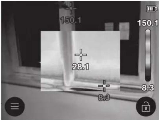
For better orientation (= assignment of the displayed thermal image to a location in the room), a standard image can be overlaid on areas with balanced temperature ranges.
Note: When a standard image and a thermal image are overlaid, they exactly overlap at a distance of 1 m. Due to the operating principle, a shift will occur between the standard image and the thermal image at different distances from the measuring object. This shift can be compensated for with special Bosch applications. You can find information about the applications and their compatibility on the measuring tool's product page or at www.bosch-professional.com/thermal.
You have the following options with the measuring tool:
- 100% IR image
Only the thermal image is displayed.

sparent
The displayed thermal image is placed transparently over the normal image. This makes it easier to see objects.
The displayed thermal image is placed transparently over the normal image. This makes it easier to see objects.
To activate/deactivate the setting, go to the left side panel and scroll to the menu item /
. Confirm the selection by pressing the multifunction button (17) in the center.
Picture-in-picture
The displayed thermal image is cropped, and the surrounding area is shown as a normal image. This setting makes it easier to determine the location of the measurement area.
To activate/deactivate the setting, go to the left side panel and scroll to the menu item /
. Confirm the selection by pressing the multifunction button (17) in the center.
Adjusting the colors in the display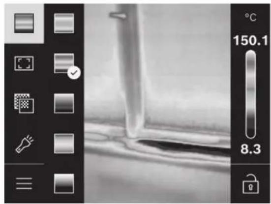
Depending on the measurement situation, different color palettes can facilitate the analysis of the thermal image and show objects or conditions more clearly on the display. The measured temperatures are not affected by this. Only the representation of the temperature values changes.
To change the color palette, open the side panel and scroll to the menu item "Color palette". Confirm the selection by pressing the multifunction button (17) in the center.
Locking the scale
The color distribution of the thermal image is adjusted automatically, but the adjustment can also be locked by pressing the
multifunction button (17) to the right and then in the center. This makes it possible not only to compare thermal images taken under different temperature conditions (for example, when checking several rooms for thermal bridges), but also to hide an extremely cold or hot object on the thermal image that would give a false representation (for example, a radiator as a hot object when searching for thermal bridges).
To set the scale back to automatic mode, open the right side panel and press the
multifunction button (17) in the center. The temperatures are now displayed dynamically again and adapt to the measured minimum and maximum values.
Main menu
Open the left side panel (see "Navigating the various menus", Page 108). Press the multifunction button (17) in the center to go to the main menu.
- Under this menu item you can delete the stored images individually, or all at once.
-
- (a)
For some of the most common materials, it is possible to choose between stored emissivity factors. To make searching easier, the values are grouped in the emissivity factor catalog. First select the appropriate category in the menu item , and then the appropriate material. If you know the exact emissivity factor of the measuring object, you can also enter this as a value under the menu item
.
• (b)
The setting of this parameter can improve the measurement result, especially in connection with materials with low emissivity (= high reflection). In some situations (especially indoors), the reflected temperature corresponds to the ambient temperature. If objects with large temperature deviations near highly reflective objects can affect the measurement, you should adjust this value. You do this by pressing the multifunction button (17) to the left or right.
-
To ensure high accuracy over the entire measuring range, measurements are taken in two temperature ranges. In the measuring function, the measuring tool automatically selects the appropriate temperature range using the temperature distribution on the thermal image. It is then determined how many measured values lie above a certain temperature limit. If very small but hot objects are to be measured, it may happen that the low temperature range, which is unsuitable for high temperatures, is selected. This can be recognized by the symbol \~ in front of the temperature display. In that case, you must switch to the measuring function <100 °C ... 450 °C> or <-20 °C ... 100 °C>, where the color distribution corresponds to the set temperature range. The setting is marked on the scale with an arrow pointing up or down.
The point is displayed in the center of the thermal image and shows the measured temperature value at that location.
The hottest point (= measurement pixel) is marked by a red crosshair on the thermal image. This makes it easier to search for critical locations (for example, a loose contact clamp in the switch cabinet).
The coldest point (= measurement pixel) is marked by a blue crosshair on the thermal image. This makes it easier to search for critical locations (for example, a leak around a window).
The average temperature (c) is displayed at the top left of the thermal image (average temperature of all measured values on the thermal image). This can make it easier for you to determine the reflected temperature.
You can adjust the brightness of the display backlight under this menu item.
Under this menu item, you can select the time interval for when the work light should turn off automatically if no button is pressed.
-
Under this menu item, you can select how long the measuring tool should wait before automatically turning off if no button is pressed. You can also disable the automatic shutdown by selecting the appropriate setting.
•
In this submenu, you can change the settings for time and date as well as their respective formats.
-
Under this menu item, you can select the language to be used on the display.
-
Under this menu item, you can reset the measuring tool to factory settings and delete all data permanently. This may sometimes take several minutes. Press the multifunction button (17) on the right to delete all files, or the multifunction button (17) on the left to cancel the process.
-
Under this menu item, you can retrieve information about the measuring tool. There you will find the serial number of the measuring tool and the installed software version. You will also find more information about the measuring tool and the software update.
To close any menu and return to the standard display screen, you can also press the measuring button (6).
Updating the measuring tool's software
If necessary, you can update the software of the measuring tool via the USB Type-C® interface. You can find information about this at
www.bosch-professional.com/thermal-update.
Documentation of measurement results
Large measurement results
The measuring tool starts measuring shortly after being switched on and continues to measure continuously until it is switched off. To save an image, point the camera at the desired measuring object and press the measuring button (6). The image is saved in the internal memory of the measuring tool. The measurement is frozen and
112 | Norwegian
displayed on the screen. This allows you to examine the image closely and make adjustments (for example, the color palette). If you do not wish to save the frozen image, restart the measuring mode with the measuring button (6). If you want to save the image in the measuring tool's internal memory, press the multifunction button (17) in the middle.
Retrieving saved images
To retrieve saved thermal images, follow these steps:
- Press the multifunction button (17) in the middle again immediately after saving. The preview image of the last saved image is now displayed on the screen.
- Alternatively, you can retrieve the saved images under the menu item .
- To switch between the saved thermal images, press the multifunction button (17) to the right or left. In addition to the thermal image, the regular image has also been saved. Press the multifunction button (17) up or down to retrieve this.
After 5 seconds, the measuring tool switches to full-screen view. In full-screen view, the title bar is hidden, so you can see all the details of the thermal image.
You can switch the view by pressing the multifunction button (17) up and down.
Deleting saved images
Press the multifunction button (17) in the middle to delete individual or all thermal images. A submenu opens.
- Here you can choose whether you want to delete only this image or all images. Confirm your selection with the multifunction button (17) in the middle. When you select , you can choose between and . Confirm your selection with the multifunction button (17) in the middle.
- In this submenu, you can also view information about emissivity and reflected temperature.
Data fragments in the images remain in the image and can be reconstructed. To delete permanently, select
→ in the main menu.
Data transfer
Data transfer via USB interface
Open the cover (11) of the USB Type-C® connector. Connect the measuring tool's USB Type-C® plug (12) to the computer using the supplied USB Type-C® cable (16). Then switch on the measuring tool with the on/off button (18). Open the file manager on the computer and select the drive GTC_450. The stored files can be copied from the measuring tool's internal memory, moved to the computer, or deleted. When the desired operation is finished, disconnect the drive from the computer as standard and then switch off the measuring tool with the on/off button (18) again.
Note: Always log off the drive from the operating system (eject the drive) first, otherwise the internal memory of the measuring tool may be damaged.
Remove the USB Type-C® cable and close the cover (11). Make sure that the cover of the USB interface is always closed so that dust or water splashes cannot penetrate the housing.
Note: Connect the measuring tool exclusively to a computer via USB. The measuring tool can be damaged if it is connected to other devices.
Note: The USB Type-C® interface should only be used for data transfer. It cannot be used for battery charging.
Processing thermal images
You can process the stored thermal images with special Bosch applications. You can find information about the applications and their compatibility on the measuring tool's product page or at www.bosch-professional.com/thermal.
Errors - Cause and remedy
If an error occurs, the measuring tool restarts and can then be used again. The overview below with persistent error messages can help you if this does not happen.
Error Cause Remedy
| Måleverktøyet kan ikke slåspå. | Tomt batteri Lad det oppladbare batteriet eller skift ut engangsbatteriene. | |
| Batterifeil Skift ut det oppladbare batteriet eller engangsbatteriene. | ||
| For varme eller for kaldebatterier | La batteriet kjøle seg ned, eller bytt ut batteriet/batteriene. | |
| Måleverktøyet er for varmteller for kaldt | La måleverktøyet få driftstemperatur. | |
Error Cause Remedy
USB connector or USB cable defective
Check whether it is possible to connect the measuring tool to another computer. If not, send the measuring tool to an authorized Bosch service center.
The measuring tool cannot be connected to a computer.
Note: Always use the USB cable supplied with the product.
Button cell battery empty Replace the button cell battery (see "Replacing the button cell battery (see figure C)", page 113). Confirm the change with "OK" by pressing the multifunction button (17) in the middle.
Glossary
You can find more information at www.bosch-professional.com/thermal.
IR thermal radiation
IR thermal radiation is electromagnetic radiation emitted by all bodies above 0 K (-273 °C). The amount of radiation depends on the temperature and emissivity of the body.
Emissivity
An object's emissivity depends on the material and surface structure. It indicates how much IR thermal radiation the object emits compared to an ideal thermal radiator (black body, emissivity ε = 1) and therefore has a value between 0 and 1.
Thermal bridge
The term thermal bridge is used for a location on a building's exterior wall where, due to the construction, a locally high heat loss occurs.
Thermal bridges can lead to an increased risk of mold.
Reflected temperature / an object's reflective properties
The reflected temperature is the thermal radiation that does not come from the object itself. Depending on the structure and material, ambient radiation is reflected in the object to be measured, thus causing the actual temperature result to be incorrect.
Object distance
The distance between the measuring object and the measuring tool affects the size of the recorded surface per pixel. With increasing object distance, you can record larger objects.
| Avstand (m) Større IR-piksel (mm) | Bredde × Høyde IR-område (m) |
| 0,30 1,14 ~ 0,29 × 0,22 | |
| 0,55 2,08 ~ 0,53 × 0,40 | |
| 1,00 3,79 ~ 0,97 × 0,73 | |
| 2,00 7,58 ~ 1,94 × 1,46 | |
| 5,00 18,95 ~ 4,85 × 3,64 |
Service and maintenance
Maintenance and cleaning
Store and transport the measuring tool only in a suitable container such as the original packaging.
Ensure that the measuring tool is always clean. A dirty IR sensor (5) can reduce measurement accuracy.
During cleaning, no liquid must enter the measuring tool.
Do not attempt to remove dirt from the infrared sensor (5), camera (3), work light (4), or laser output opening (2) with sharp objects. Do not wipe the IR sensor and camera (risk of scratches).
Clean the surfaces of the laser output opening regularly. Pay attention to lint.
Contact an authorized Bosch service center if you wish to have the measuring tool recalibrated.
Send the measuring tool in the original packaging if repair is needed.
The measuring tool contains no parts that can be serviced by the user. The measuring tool can be damaged if the housing cover is opened.
Replacing the button cell battery (see figure C)
Open the cover (11).
Unscrew the screw (10) on the holder for the button cell battery. Pull the holder for the button cell battery (9) out of the measuring tool. Replace the button cell battery. Screw the screw (10) back in after inserting the holder for the button cell battery.
After-sales service and customer advice
Our after-sales service responds to your questions concerning the repair and maintenance of your product as well as spare parts.
Exploded views and information on spare parts can also be found at: www.bosch-pt.com
The Bosch advice team will be happy to help you with any questions about our products and their accessories.
In all correspondence and spare parts orders, please always include the 10-digit product number given on the product's nameplate.
Norwegian
Robert Bosch AS
Postboks 350
114|Finnish
1402 Ski
Tel.: 64 87 89 50
Fax: 64 87 89 55
Further service addresses can be found at:
www.bosch-pt.com/serviceaddresses
Transport
The recommended Li-ion batteries are subject to the requirements for dangerous goods. The batteries can be transported by road by the user without further requirements.
When shipping is carried out by third parties (e.g., air transport or freight forwarding), special requirements for packaging and labeling must be met. You must consult a dangerous goods expert when preparing the shipment.
Only send batteries if the housing is not damaged. Tape over the open contacts and pack the battery so that it does not move in the packaging. Also follow any additional national regulations.
Disposal

Measuring tools, batteries, accessories, and packaging must be disposed of in an environmentally friendly manner.
Measuring tools and rechargeable batteries / disposable batteries must not be disposed of with regular household waste!
Only for EU countries:
Measuring tools that are no longer usable, and defective or depleted rechargeable batteries/disposable batteries, must be separated for recycling. Use the collection systems provided for this purpose.
Improper disposal of used electrical and electronic equipment containing hazardous substances can have harmful effects on the environment and human health.
Batteries:
Li-ion:
Read the information in the Transport section (see "Transport", page 114).
Finnish
Safety instructions

To ensure safe and secure operation of the measuring tool, all instructions provided must be read and followed. If the measuring tool is not used in accordance with these instructions,
the protection of the measuring tool may be compromised. Never cover or remove warning labels on the measuring tool. KEEP THESE INSTRUCTIONS IN A SAFE PLACE AND PASS THEM ON TO THE NEXT USER ALONG WITH THE MEASURING TOOL.
- Warning – risk of dangerous radiation exposure if you use equipment or procedures other than those specified here. ▶ The measuring tool is supplied with a laser warning label (marked on the drawing of the measuring tool on the image page).
- If the text on the laser warning label is not in the language of the country of use, affix the supplied label in the language of the country of use over it before first use.
Do not direct the laser beam at people or animals, and do not look into the visible or reflected laser beam. The laser beam can cause glare, accidents, or eye damage.
- If the laser beam hits your eye, deliberately close your eyes and immediately turn your head away from the beam path.
- Do not make any modifications to the laser equipment.
- Do not use laser viewing glasses (accessory) as protective goggles. Laser viewing glasses make the laser beam easier to see; they do not protect against laser radiation.
- Do not use laser viewing glasses (accessory) as sunglasses or in road traffic. Laser viewing glasses do not provide full UV protection and impair color recognition.
Have a defective measuring tool repaired only by an authorized professional and only with original spare parts. This ensures that the measuring tool remains safe.
- Do not allow children to use the laser measuring tool without supervision. Children may pose a glare hazard to themselves or others.
- Do not use the measuring tool in explosive environments with flammable liquids, gases, or dust. Sparks may be generated in the measuring tool, which could ignite the dust or vapors.
- Do not open the battery or make any modifications to it. Risk of short circuit.
Vapors may be released from the battery if it is damaged or used improperly. The battery may catch fire or explode. Ensure adequate ventilation and consult a doctor if you experience irritation. Vapors may irritate the respiratory tract.
In case of misuse or a damaged battery, flammable liquid may leak from the battery. Avoid contact with the liquid. If liquid accidentally gets on your skin, rinse the affected area with water. If liquid gets into your eyes, also consult a doctor. Liquid leaking from the battery may cause skin irritation and burns.
Sharp objects (for example, nails and screwdrivers) or impacts to the casing may damage the battery. This can lead to a short circuit, fire, smoke, explosion, or overheating.
Make sure that the removed battery does not come into contact with paper clips, coins, keys, nails, screws, or other small metal objects, as they can short-circuit the battery contacts. A short circuit between the battery contacts can lead to burns and fire. Use the battery only in products from the manufacturer. Only in this way can you prevent dangerous overloading of the battery. ▶ Charge the batteries only with chargers recommended by the manufacturer. A charger that is suitable for one type of battery may create a fire hazard when used with another type of battery.

Protect the battery from heat, for example, prolonged sunlight, fire, dirt, water, and moisture. There is a risk of explosion and short circuit.
WARNING

Make sure that children cannot get hold of the button cell. Button cells are dangerous.
Button cells must never be swallowed or inserted into other body orifices. If you suspect that a button cell has been swallowed or inserted into another body orifice, seek medical attention immediately. A swallowed button cell can cause severe internal burns and death within 2 hours. ▶ Replace the button cell properly. Otherwise, there is a risk of explosion. Use only the button cells specified in this instruction manual. Do not use other button cells or power sources. - Do not attempt to charge button cells or short-circuit them. The button cell may leak, explode, catch fire, and cause injuries. ▶ Remove and dispose of empty button cells properly. Empty button cells can leak and thereby damage the product or people. - Do not overheat the button cell or throw it into a fire. The button cell may leak, explode, catch fire, and cause injuries. - Do not damage or disassemble the button cell. The button cell may leak, explode, catch fire, and cause injuries. - Do not allow a damaged button cell to come into contact with water. Leaking lithium can form hydrogen with water and may therefore lead to fire, explosion, or injury. Stop using the measuring device if the button cell holder can no longer be closed properly and completely. Remove the button cell and have the measuring device repaired. ▶ Large temperature differences in the thermal image can cause even high temperatures to be displayed in a color that is perceived as a low temperature. Contact with such a surface can cause burns.
Accurate temperature measurements are only obtained when the emissivity set on the device matches the emissivity of the target. Otherwise, the temperature of objects may be displayed as too high or too low. Touching such a surface can then cause a hazardous situation. - Do not point the measuring device at the sun or at high-power CO₂ lasers. This can damage the detector. In particular, protect the camera and infrared lens areas of the measuring device from moisture, snow, dust, and dirt. Otherwise, the receiver lens may fog up or become dirty, which can distort measurement results. Incorrect device settings and unfavorable environmental conditions may lead to measurement errors. The temperature of objects may be displayed as too high or too low, which can lead to danger if that surface is touched.
Product description and features
Note the figures at the beginning of the operating instructions.
Intended use
This thermal camera is intended for non-contact measurement of surface temperatures.
The thermal image on the display shows the temperature distribution within the camera's field of view and thus allows temperature differences to be displayed in different colors.
When used correctly, the device can be used to non-contact investigate temperature differences and anomalies on surfaces and objects in order to reveal structures and/or potential damage. Examples of objects to be inspected are:
- thermal insulation and insulating capacity (e.g., locating thermal bridges),
- in-use heating and hot water pipes (e.g., underfloor heating) in floors and walls,
- overheated electrical components (e.g., fuses or connectors),
- defective or damaged machine parts (e.g., overheating due to defective ball bearings).
The measuring device is not suitable for measuring the temperature of gases.
The measuring device must not be used for human medical purposes.
For more information on veterinary use, visit www.bosch-professional.com/thermal.
It is suitable for use indoors and outdoors.
This product is a consumer laser product in accordance with standard EN 50689.
The light of this measuring tool is intended to illuminate the working area in front of the tool for taking pictures. It should not be used for continuous illumination of the work area.
The laser point must not be used as a laser pointer. It is intended only for marking the measuring area.
Parts described
The numbering of the parts described refers to the illustration of the measuring tool on the graphics page.
(1) Protective cap
(2) Laser beam outlet
(3) Visual camera
(4) Work light
(5) Infrared sensor
(6) Pause/start measurement button
(7) Battery compartment
(8) Laser warning label
(9) Button battery holder
(10) Screw for the battery compartment holder
(11) Cover for the USB port and battery compartment holder
(12) USB Type-C® port a)
(13) Laser button
(14) Battery/battery adapter release button
(15) Battery b)
(16) USB Type-C® cable b)
(17) Multi-function button
(18) Power/Back button
(19) Display
(20) Serial number
(21) Battery adapter cover
(22) Batteries b)
(23) Battery adapter cover
a) USB Type-C and USB-C are registered trademarks of USB Implementers Forum.
b) The described accessory is not included in the standard delivery.
Display elements
(a) Emissivity display
(b) Reflected temperature display
(c) Average temperature display
(d) Memory full symbol
(e) Work light symbol
(f) Laser symbol
(g) Charge status display
(h) Display of maximum surface temperature in measuring range
(i) Scale
(j) Display of minimum surface temperature in measuring range
(k) Temperature scale lock symbol
(I) Cold spot display (example)
(m) Crosshair and thermometer
(n) Hot spot display (example)
(o) Menu symbol
Technical data
Thermal camera GTC 12V-450-13
| Tuotenumero | 3 601 K83 900 |
| Infrapuna-anturin tarkkuus 256 × 192 px | |
| Terminen herkkyysA) | ≤ 50 mK |
| Spektrialue 8–14 μm | |
| Kuvakulma (FOV)A) | 55,6° × 42° |
| Erotustarkkuus (IFOV) 3,79 mrad | |
| Polttopisteen etäisyysA) | ≥ 0,5 m |
| Polttopiste Kiinteä | |
| Lämpökuvan virkistystaajuus ≤ 9 Hz | |
| Pintalämpötilan mittausalueA) | -20...+450 °C |
| Pintalämpötilan mittaustarkkuusA)(B)(C) | |
| >0 °C ... ≤ +100 °C0) | ±2 °C |
| >+100 °C€) | ±2% |
| Lämpötilatarkkuus 0,1 °C | |
| Näytön tyyppi TFT | |
| Näytön koko 2,8" | |
| Näytön tarkkuus 480 × 360 px | |
| Sisäänrakennetun visuaalisen kameran tarkkuus 2 MP (640 × 480 px) | |
| Kuvaformaatti .jpg | |
| Tallennettuja elementtejä per tallennuskerta 1 × lämpökuva (kuvakaappaus),1 × visuaalinen todellinen kuva sisältäen lämpötila-arvot (metatiedot) | |
Thermal camera GTC 12V-450-13
| Sisäisen kuvamuistin suurin kuvamäärä 500 | |
| Suurin käyttökorkeus merenpinnan tasosta 2 000 m | |
| Likaisuusaste standardin IEC 61010-1 mukaan 2 | r) |
| Suurin sallittu suhteellinen ilmankosteus A) | 90% |
| Laserluokka 2 | |
| Lasertyyppi < 1 mW, 645–660 nm | |
| Lasersäteen hajonta 1,5 mrad (täysi kulma) | |
| Virtalähde | |
| - Akku (litiumioni) 12 V | |
| - Paristot (alkali-mangaaniparistot paristoadapterin kanssa) 4 × 1,5 V LR6 (AA) | |
| - Akkuparistot (NiMH paristoadapterin kanssa) 4 × 1,2 V HR6 (AA) | |
| Käyttöaika G) | |
| - Akku (litiumioni) H | 8 h |
| - Paristot (alkali-mangaani) 4 h | |
| Järjestelmäajan virtalähde CR1225 (3 V:n litiumioniparisto) | |
| USB-standardi 2.0 | |
| USB-liitäntä USB Type-C ® | |
| Paino J) | 0,354 kg |
| Mitat (pituus × leveys × korkeus) K) | 89 × 79 × 209 mm |
| Kotelointiluokka (paitsi akku/paristot, pystyasennossa) IP54 | |
| Suositeltu ympäristön lämpötila latauksen aikana 0...+35 °C | |
| Sallittu ympäristön lämpötila | |
| - käytössä -10...+50 °C | |
| - Säilytyksessä akun kanssa | -20...+50 °C |
| - Säilytyksessä ilman akkua | -20...+70 °C |
| Suositellut akut | GBA 12V... |
| Suositellut latauslaitteet | GAL 12...GAX 18... |
A) According to VDI 5585 standard (average)
B) At ambient temperature of 20–23 °C and emissivity ≥ 0.95, measuring distance: 1 m, operating time: > 5 min, 150 mm aperture, work light and laser switched off
C) Additionally, deviation depending on the application (e.g., reflection, distance, and ambient temperature)
D) Applies to the center point, for all other pixels additionally ±1 °C
E) Applies to the center point, for all other pixels additionally ±1%
F) This is only non-conductive dirt. However, the tool may occasionally become temporarily conductive due to condensation.
G) With work light switched off and display at medium brightness
H) Depending on the battery used
I) At ambient temperature of 20-30°C
J) Weight without battery/battery adapter/batteries
K) GBA 12V 2.0Ah battery or with the battery adapter
The type plate contains the serial number (20) of the product, which is the unique identification number of the measuring tool.
Power supply for the measuring tool
The measuring tool can be operated either with a Bosch lithium-ion battery, conventional batteries, or conventional NiMH rechargeable batteries.
Operation with battery (see figure A)
Use only the chargers specified in the technical data. Only these chargers are suitable for the lithium-ion battery used in your measuring tool.
Note: In accordance with international transport regulations, Li-ion batteries are supplied partially charged. To ensure full battery capacity,
the battery must be fully charged before first use.
Insert the charged battery (15) into the battery slot (7) until it locks securely into place.
To remove the battery (15), press the release buttons (14) and pull the battery out of the battery slot (7).
Do not forcibly remove the battery.
Operation with batteries (see figure B)
We recommend using alkaline-manganese batteries or NiMH batteries with the measuring tool.
The batteries are inserted into the battery adapter.
- The battery adapter is intended for use only with original Bosch measuring tools and must not be used with power tools.
To insert the batteries, push the battery adapter cover (21) into the battery compartment (7). Insert the batteries into the cover as shown in the figure on the lid (23). Push the lid onto the cover until it clicks audibly into place.
To remove the batteries (22), press the release buttons (14) on the lid (23) and pull the lid off. Take out the batteries. To remove the cover (21) from inside the battery compartment, grip the cover, press it lightly against the side wall, and pull it out of the measuring tool.
Always replace all batteries/rechargeable batteries at the same time. Always use batteries/rechargeable batteries from the same manufacturer and with identical capacity.
▶ Remove the batteries/rechargeable batteries from the measuring tool if you will not be using it for an extended period. Batteries and rechargeable batteries may corrode if stored for a long time inside the measuring tool.
Tips for optimal handling of the battery
Protect the battery from moisture and water.
Store the battery only at temperatures between -20 ... 50 °C. Do not leave the battery in a car for a long time on a hot summer day, for example.
A significantly shortened operating time after charging indicates that the battery has reached the end of its service life and must be replaced with a new one. Observe the disposal instructions.
Operation
- Protect the measuring tool from moisture and direct sunlight. Do not expose the measuring tool to extremely high/low temperatures or large temperature fluctuations. Do not store the tool for extended periods, e.g., in a hot car. After large temperature fluctuations, allow the measuring tool to adjust to the ambient temperature before putting it into operation. Extreme temperatures or temperature fluctuations may impair the accuracy of the measuring tool. ▶ Allow the measuring tool to adapt to the ambient temperature.
With large temperature differences, adaptation can take up to 60 minutes. For example, if you store the measuring tool in a cold car and then take a measurement in a warm building.
- Do not expose the measuring tool to hard impacts or drops. Have the measuring tool checked at an authorized Bosch service center if the tool's housing has been subjected to strong impacts or if you notice any malfunctions in the tool.
Initial operation
On first use
When you turn on the measuring device for the first time or after resetting it to factory settings, some basic settings must be made. Select the desired values by pressing the multi-function button (17) down, up, left, or right. Confirm your selection by pressing
the multi-function button (17) in the center. As soon as you confirm your selection, the next setting appears on the display. The status bar at the top shows the total number and the number of remaining settings.
The following basic settings are available:
Switching on and off
Open the protective cap (1) for measuring. During work, ensure that the infrared sensor is not closed or covered.
Switch on the measuring device by pressing the power button (18). The display (19) shows a startup sequence. After the startup sequence, the measuring device starts measuring immediately and continues until the device is switched off.
Note: The measuring device may calibrate itself several times during the first minutes because the sensor and ambient temperatures have not yet equalized. Re-calibration of the sensor enables accurate measurement.
During equalization, a "~" symbol may appear in the temperature display. This phenomenon intensifies if the ambient temperature fluctuates strongly. Therefore, it is advisable to switch on the measuring device a few minutes before starting the measurement so that its temperature can equalize.
Switch off the measuring device by pressing the power button (18)
for 1 second. The measuring device saves all settings and switches off. Close the protective cap (1) to transport the measuring device safely.
You can select from the main menu whether the measuring device switches off automatically and after what time this occurs (see "Main menu", page 121).
If the battery or device temperature is outside the operating temperature specified in the technical data, the device switches off automatically after a short warning period (see "Faults – causes and corrective measures", page 122). Allow the temperature to equalize and then switch the device on again.
Navigating the menus
Navigating the various menus of the measuring device:
- Opening menu bars: press the multi-function button (17) in the center or to the left.
The menu bars on the right and left are displayed on the screen, with the main menu highlighted.
- To browse the left menu bar / navigate in the main menu: press the multi-function button (17) up, down, left, or right.
- To switch to the left or right menu bar: press the multi-function button (17) left or right.
- To confirm a selection / switch to a submenu: press the multi-function button (17) in the center.
- To return from a submenu to a higher-level menu: press the Back button (18).
Preparing the measurement
Setting the emissivity for surface temperature measurements
The emissivity of an object depends on the material and the surface structure. It indicates how much infrared thermal radiation the object reflects compared to an ideal thermal radiator (black body, emissivity ε = 1). Correspondingly, the value is between 0 and 1.
The surface temperature is determined by non-contact measurement of the object's natural infrared thermal radiation. To obtain correct measurement results, the emissivity set on the measuring device must be checked before each measurement and adjusted to the measuring object if necessary.
The emissivities preset on the measuring device are approximate values.
You can select one of the preset emissivity values or enter an exact numerical value. Set the desired emissivity via the menu → (see "Main menu", page 121).
Correct results in temperature measurement are only obtained when the emissivity set on the device and the emissivity of the object match each other.
The lower the emissivity, the greater the influence of the reflected temperature on the measurement result. Therefore, the reflected temperature must always be adjusted if you change the emissivity. Set the reflected temperature via the menu → (see "Main menu", page 121).
Temperature differences displayed by the measuring device may in reality be due to different temperatures and/or different emissivities. If there are very large differences in emissivities, the displayed temperature differences may deviate significantly from the actual values.
If there are multiple measuring objects made of different materials or with different structures in the measuring range, the device displays temperature values accurately only for those objects that match the set emissivity. For all other objects (with different emissivities), temperature relationships can be inferred from the displayed color differences.
Notes on measurement conditions
Highly reflective or glossy surfaces (e.g., shiny tiles or bare metals) can significantly distort or degrade the displayed results. If necessary, cover the measurement area with a dark, matte, and thermally conductive tape. Allow the tape to adapt to the surface temperature for a moment.
If there are reflective surfaces nearby, choose an appropriate measurement angle so that thermal radiation reflected from other objects does not distort the measurement result. For example, when measuring objects directly in front of you, reflection of your own body heat can interfere with proper measurement. The device may display the contours and temperature of your body (reflected value) when measuring a flat surface, which does not correspond to the actual temperature of the measured surface (emitted value or true value).
Measuring through transparent materials (e.g., glass or transparent plastics) is not possible due to the operating principle.
The more favorable and stable the measurement conditions, the more accurate and reliable the measurement results. Strong fluctuations in ambient temperature and also in the temperature of the measured object can reduce accuracy.
Smoke, steam, high humidity, and dusty air distort the results of infrared temperature measurement.
Guidelines for even more accurate measurement:
- Get as close as possible to the measurement point to minimize interfering factors between you and the measurement surface.
- Ventilate the rooms before measurement, especially if there is a lot of dust or steam in the air. After ventilation, allow the room temperature to stabilize until it returns to normal levels.
Marking the measurement point
- Never point the laser beam at people or animals, and do not look into the laser beam yourself, even from a distance.
The measuring device is equipped with a laser for marking the measurement point.
Press and hold the laser button (13). The laser symbol (f) appears in the status bar, and a red circle is shown around the crosshair (m). The laser and crosshair are precisely aligned at a distance of 1 meter. The laser turns off when you release the laser button (13).
Assigning temperatures to the scale
The scale (i) is displayed on the right side of the screen. The values at the top and bottom depend on the maximum temperature (h) and minimum temperature (j) recorded in the thermal image. The scale analyzes 99.99% of all pixels. The color assigned to the temperature value in the image is distributed evenly (linearly).
The temperatures of the site can be assigned to different color shades within these two limit values. For example, a temperature exactly between the maximum and minimum values is assigned to the middle area of the scale.
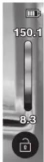
When you want to determine the temperature of a specific area, aim the measuring tool so that the crosshair and the thermometer (m) are aligned with the desired point or area. In automatic setting, the color spectrum of the scale always distributes linearly (= evenly) over the entire measuring range within the maximum and minimum temperatures.
The measuring tool displays all temperatures measured within the measuring range in relation to each other. If the temperature of an area appears, for example, in a colored representation as bluish, it means that the bluish areas belong to the zones of cold values within that measuring range. Nevertheless, the temperature of these zones may be in a temperature range that can, in certain cases, cause a risk of injury. Therefore, always remember to take into account the temperatures indicated on the scale or directly at the crosshair.
Functions
Note the information regarding navigation in the various menus (see "Navigating in the various menus", page 118)

Illumination of the measuring object
The measuring tool is equipped with a work light (4). It is intended to illuminate the working area in front of the measuring tool for taking images. It should not be used for continuous illumination of the work area.
To switch the work light on/off, open the left side bar. Scroll to the menu item / and confirm your selection. When the work light is switched on, this is indicated in the status bar.
The light switches off automatically after two minutes to avoid affecting the accuracy of the measurement.
You can set the automatic switch-off time in the menu item .
Overlaying the thermal image and the real image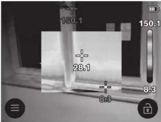
When the temperature ranges are uniform, you can switch on a visual, real image in addition to the thermal image for a better image (= to locate the areas of the displayed thermal image).
Note: The overlay of the real image and the thermal image is precisely aligned at a distance of 1 meter. If the distances to the measuring object are different, there will always be a parallax error between the real image and the thermal image. This parallax error can be compensated with special Bosch apps. Information about the apps and their compatibility can be found on the product page of the measuring tool or at www.bosch-professional.com/thermal.
The measuring tool offers the following setting options:
- 100% infrared image
The device displays only the thermal image.

visible
The displayed thermal image is placed transparently over the real image. This makes it easier to identify objects. To activate/deactivate this setting, open the left sidebar and scroll to the menu item / . Confirm your selection by pressing the multi-function button (17) in the center.

in image
The displayed thermal image is cropped and the surrounding area is shown as a real image. This setting makes it easier to locate the measurement area.
To activate/deactivate this setting, open the left sidebar and scroll to the menu item / . Confirm your selection by pressing the multi-function button (17) in the center.
Adjusting the color display mode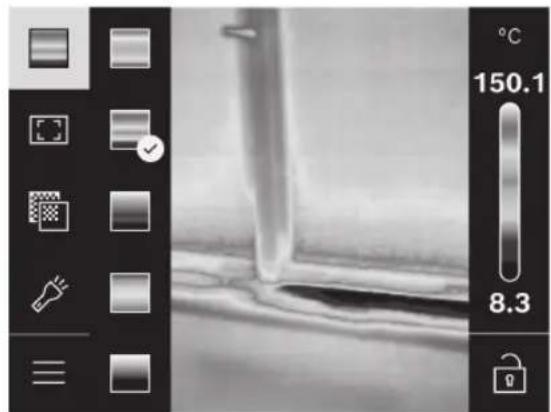
Depending on the measurement situation, different color palettes may make it easier to analyze the thermal image and depict the objects or content shown on the screen more clearly. This does not affect the measured temperatures. It only changes the representation of the temperature values.
To change the color palette, open the sidebar and scroll to the "Color palette" menu item. Confirm your selection by pressing the multi-function button (17) in the center.
Locking the scale
The color distribution of the thermal image is adjusted automatically, but it can also be locked by pressing the multi-function button (17) to the right and then in the center. This allows comparison of thermal images saved under different temperature conditions (e.g., when inspecting multiple rooms for cold bridges) or removing an extremely cold or hot object from the thermal image that would otherwise distort the image (e.g., a radiator as a hot object when looking for cold bridges).
To switch the scale back to automatic, open the right sidebar and press the multi-function button (17) in the center. Then the temperatures will behave dynamically again and adapt to the measured minimum and maximum values.
Main menu
Open the left sidebar (see "Navigating in the menus", Page 118). Go to the main menu by pressing the multi-function button (17) in the center.
- In this menu item you can delete saved images one by one or all at once.
• (a)
For some of the most common materials, stored emissivity values are available. To make searching easier, the values are grouped in the emissivity list. First select the appropriate category and then the appropriate material from the menu item. If you know the exact emissivity of the measurement object, you can also enter it as a numerical value in the menu item.
- (b)
Adjusting this parameter can improve the accuracy of the measurement result, especially in materials with low emissivity (= strong reflection). In some situations (especially indoors), the reflected temperature corresponds to the ambient temperature. It is worth adjusting this value if strongly reflecting objects near objects with very different temperatures could impair the accuracy of the measurement result. To do this, press the multi-function button (17) to the left or right.
-
Measurements are made in two temperature ranges to ensure high accuracy over the entire measurement range. In measurement mode, the device automatically selects the appropriate temperature range based on the temperature distribution of the thermal image. This analyzes how many measurement values exceed a certain temperature threshold. If measuring very small but hot objects, the device may select a low temperature range that is not suitable for high temperatures. This can be identified by the symbol \~ preceding the temperature reading. In this case, switch to the measurement mode <100 °C ... 450 °C> or <-20 °C ...
100 °C>, whose color distribution is suitable for the set temperature range. The setting is indicated by an arrow pointing up or down on the scale.
-
• (m): / The point is visible in the center of the thermal image and shows the measured temperature value at that point. • (n): / The hottest point (= measurement pixel) is marked in the thermal image with a red crosshair. This makes it easier to find problem areas (e.g., a loose connector in a switch cabinet). • (I): / The coldest point (= measurement pixel) is marked in the thermal image with a blue crosshair. This makes it easier to find problem areas (e.g., a leak point in a window).
vassa sinisellä lankaristillä. Tämä helpottaa ongelma- kohtien etsimistä (esim. ikkunan vuotokohta).
- (i): /
- (c): /
The average temperature (c) is displayed in the upper left corner of the thermal image (the average temperature of all measured values in the thermal image). This can help in determining the reflected temperature.
-
•
In this menu item, you can adjust the brightness of the display lighting.
•
In this menu item, you can select the time interval after which the work light turns off automatically if no button is pressed.
•
In this menu item, you can select the period after which the measuring device turns off automatically after the last button press. You can also deactivate the automatic shutdown by selecting the setting .
•
In this submenu, you can set the time and date, as well as their display format.
-
In this menu item, you can select the language used on the display.
•
In this menu item, you can restore the measuring device to factory settings and permanently delete all data. This may take several minutes. Then press the multi-function button (17) to the right to delete all data, or press the multi-function button (17) to the left to cancel the operation.
-
In this menu item, you can access information about the measuring device. There you will find the serial number of the device and the installed software version. You will also find additional information about the measuring tool and software updates.
You can also exit any menu and return to the standard view by pressing the measurement button (6).
Updating the measuring tool software
If necessary, you can update the measuring tool software via the USB Type-C® connection. For more information, visit:
www.bosch-professional.com/thermal-update.
Documenting measurement results
Saving measurement results
After startup, the measuring tool begins measuring immediately and continues until the tool is switched off.
To save an image, point the camera at the desired measurement target and press the measurement button (6). The image is saved to the internal memory of the measuring tool. Measurement stops and the result appears on the display. This allows careful inspection and adjustment of the image (e.g., color palette). If you do not want to
save the freeze-frame image, restart measurement mode with the measurement button (6). To save the image to the internal memory of the measuring tool, press the multi-function button (17).
Viewing saved images
To view saved thermal images, proceed as follows:
- Immediately after saving, press the center of the multi-function button (17) again. The preview of the last saved photo will now appear on the display.
- Alternatively, you can open saved photos on the display via the menu item .
- To switch between saved thermal images, press the multi-function button (17) to the right or left. In addition to the thermal image, the visual image is also saved. You can open it on the display by pressing the multi-function button (17) up or down. After five seconds, the measuring tool switches to full-screen view. In full-screen view, the header row disappears so you can examine all details of the thermal image. You can switch between views by pressing the multi-function button (17) up and down.
Deleting saved images
To delete individual thermal images or all thermal images, press the multi-function button (17) in the center. A submenu will open.
- From there, you can choose whether to delete only this image or all images. Confirm your selection by pressing the multi-function button (17) in the center. In the selection area, you can choose between the options. Confirm your selection by pressing the multi-function button (17) in the center.
- In this submenu, you can also view information regarding emissivity and reflected temperature.
The image data fragments remain in memory and can be reconstructed. If you want to delete them permanently, select from the main menu → .
Data transfer
Data transfer via USB interface
Open the USB Type-C® port cover (11). Connect the measuring device's USB Type-C® port (12) to the computer using the supplied USB Type-C® cable (16).
Then turn on the measuring device using the power button (18).
Open the file explorer on the computer and select the drive GTC_450.
The stored files can be copied from the measuring device's internal memory, transferred to the computer, or deleted.
As soon as you have completed the selected action, disconnect the drive from the computer in the normal way and turn off the measuring device using the power button (18).
Note: always eject the drive from your operating system first (remove the drive), otherwise the internal memory of the measuring device may be damaged.
Disconnect the USB Type-C® cable and close the cover (11).
Always keep the USB interface cover closed to prevent dust or water splashes from entering the housing.
Note: connect the measuring device to the computer only with a USB cable. The measuring device can be damaged if it is connected to other devices.
Note: The USB Type-C® connector is intended for data transfer only. It cannot be used to charge batteries or rechargeable batteries.
Post-processing of thermal images
You can post-process saved thermal images with special Bosch apps. Information about the apps and their compatibility can be found on the product page of the measuring tool or at www.bosch-professional.com/thermal.
Faults - causes and corrective measures
In the event of a malfunction, the measuring tool restarts, after which you can continue using it. Otherwise, you can refer to the overview below for advice if the tool continuously displays error messages.
Fault Cause Corrective measure The measuring tool does not start. Battery/rechargeable battery flat Charge the battery or replace the batteries.
 | Akku-/paristovika Vaihda akku tai paristot. | |
 | Akku/paristot ovat liian kuu-mia tai liian kylmiä | Anna akun/paristojen lämpötilan tasaantua tai vaihda akku/paristot. |
 | Mittalaite on liian kuuma tai liian kylmä | Anna mittalaitteen lämpötilan tasaantua. |
Fault Cause Corrective measure
The USB connection or USB cable is faulty
Try connecting the measuring tool to another computer. If this is not possible, send the measuring tool to an authorized Bosch service center.
Note: Always use the USB cable supplied.
The measuring tool cannot establish a connection to the computer.
The button cell is flat Replace the button cell (see "Replacing the button cell
(see Figure C)", page 123). Confirm the replacement with the "OK" message by pressing the multi-function button (17) in the center.
Explanation of terms
Further information can be found online at www.bosch-professional.com/thermal.
Infrared thermal radiation
Infrared thermal radiation is electromagnetic radiation emitted by any object with a temperature above 0 kelvin (-273 °C). The amount of radiation depends on the object's temperature and emissivity.
Emissivity
The emissivity of an object depends on the material and surface structure. It indicates how much the object reflects infrared thermal radiation compared to an ideal thermal radiator (black body, emissivity ε = 1). Correspondingly, the value is between 0 and 1.
Thermal bridge
A thermal bridge is a point in the external wall of a building that locally increases heat loss due to the structure. Thermal bridges can increase the risk of mold formation.
Reflected temperature / reflectivity of the object
Reflected temperature is thermal radiation that does not originate from the object itself. Depending on the structure and material, environmental radiation is reflected onto the measured object, which distorts the actual temperature measurement result.
Distance to the object
The distance between the measurement target and the measuring device affects the measured surface area size per pixel. As the distance to the object increases, you can measure increasingly larger objects.
| Etäisyys (m) Infrapunapikse-lin koko (mm) | Infrapuna-alueen le-veys × korkeus (m) |
| 0,30 1,14 ~ 0,29 × 0,22 | |
| 0,55 2,08 ~ 0,53 × 0,40 | |
| 1,00 3,79 ~ 0,97 × 0,73 | |
| 2,00 7,58 ~ 1,94 × 1,46 | |
| 5,00 18,95 ~ 4,85 × 3,64 |
Care and maintenance
Maintenance and cleaning
Store and transport the measuring device only in a suitable bag, for example the original packaging.
Always keep the measuring device clean. A dirty infrared sensor (5) can reduce measurement accuracy.
Do not allow liquid to enter the tool during cleaning.
Do not attempt to use sharp objects to remove dirt from the infrared sensor (5), camera (3), work light (4), or the laser beam outlet (2). Do not wipe the infrared sensor or camera with a cloth (risk of scratching).
Clean the surfaces of the laser outlet especially at regular intervals and remove any lint.
If you want to recalibrate the measuring tool, contact an authorized Bosch service center.
If the measuring tool is damaged, send it to service in the original packaging.
The measuring tool contains no parts that the user can service. Opening the housing can damage the measuring tool.
Replacing the button battery (see figure C)
Open the cover (11).
Unscrew the screw (10) of the button battery holder. Pull the button battery holder (9) out of the measuring tool. Replace the button battery. After installing the button battery holder, tighten its screw (10).
Customer service and usage advice
Customer service answers questions about repair and maintenance of your product as well as spare parts. Exploded views and information on spare parts can also be found at: www.bosch-pt.com The Bosch usage advice team will be happy to answer questions about products and accessories.
In all inquiries and spare parts orders, please provide the 10-digit product number indicated on the product's nameplate.
Finland
Robert Bosch Oy
Bosch central service
Pakkalantie 21 A
01510 Vantaa
You can order spare parts directly from www.bosch-pt.fi.
Tel.: 0800 98044
Fax: 010 296 1838
www.bosch-pt.fi
You can find more service addresses under:
www.bosch-pt.com/serviceaddresses
Transport
The lithium-ion batteries included in the delivery are subject to the regulations of the Dangerous Goods Act. The user may transport the batteries on the road without special measures.
When shipping via a third party (e.g., air freight or forwarding), special requirements regarding packaging and labeling must be observed. In such cases, a dangerous goods specialist must be used for preparing the shipment.
Only send batteries if the housing is undamaged.
Tape over open contacts and pack the battery so that it cannot move around in the packaging. Also observe any further-reaching national regulations.
Disposal

Disused measuring tools, batteries/rechargeable batteries, accessories, and packaging should be sent for environmentally friendly recycling.
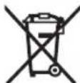
Do not dispose of measuring tools or batteries/rechargeable batteries in household waste!
Applies to EU countries only:
Dispose of decommissioned measuring devices and defective or exhausted batteries separately. Take them to appropriate collection points.
Improper disposal of old electrical and electronic equipment can have harmful effects on the environment and human health due to potentially hazardous substances they contain.
Batteries:
Li-Ion:
Follow the instructions given in the "Transport" section (see "Transport", page 124).
Safety Instructions

To work with the measuring tool safely and without risk, you must read and follow all instructions. If the measuring tool is not used
in accordance with these instructions, the protective measures integrated in the measuring tool may be adversely affected. Never damage the warning labels on the measuring tool. KEEP THESE INSTRUCTIONS SAFE AND HAND THEM OVER WITH THE MEASURING TOOL IF NECESSARY.
▶ Caution – if other than the operating or adjustment devices mentioned here are used, or
other procedures are carried out, this may lead to hazardous exposure to radiation.
▶ The measuring tool is delivered with a laser warning label (marked on the illustration of the measuring tool on the graphics page). If the text of the laser warning label is not in your country's language, stick the supplied label in your country's language over it before first use.
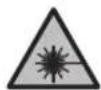
Do not direct the laser beam at persons or animals and do not look directly into the direct or reflected laser beam yourself. This can blind people, cause accidents, or damage your eyes.
▶ If the laser beam hits your eyes, you must consciously close your eyes and immediately move your head away from the beam. ▶ Do not make any changes to the laser setup. ▶ Do not use the laser glasses (accessory) as protective goggles. The laser glasses are used for better recognition of the laser beam, but they do not protect against the laser beam. ▶ Do not use the laser glasses (accessory) as sunglasses or in road traffic. Laser glasses do not offer full protection against UV radiation and reduce color perception. Have the measuring tool repaired only by qualified technical personnel and only with genuine spare parts. This ensures the safe operation of the measuring tool is maintained. Do not allow children to use the laser measuring tool without supervision. They could accidentally blind other people or blind themselves. Do not work with the measuring tool in an explosive environment where flammable liquids, gases, or flammable dusts are present. Sparks may be generated inside the measuring tool and ignite the dust or fumes. ▶ Do not modify or open the battery. There is a risk of short circuit. ▶ In case of damage or improper use of the battery, fumes may escape from the battery. The battery may ignite or explode. Let fresh air in and consult a doctor if you experience any discomfort. The fumes may irritate the respiratory tract. ▶ In case of incorrect use or a defective battery, flammable liquid may leak from the battery. Avoid any contact with it. In case of accidental contact, rinse with water. If the liquid comes into contact with the eyes, seek medical help as well. Leaking battery fluid may cause skin irritation or burns.
Leaking battery fluid may cause skin irritation or burns.
Sharp objects such as nails or screwdrivers or external force can damage the battery. This can cause an internal short circuit, resulting in ignition, smoke, explosion, or overheating of the battery. ▶ Keep unused batteries away from paper clips, coins, keys, nails, screws, and other small metal objects that can short-circuit the battery contacts. A short circuit of the battery contacts can cause injuries or fire. Use the battery only in products from the manufacturer. Only in this way is the battery protected from dangerous overcharging. ▶ Charge the batteries only with chargers recommended by the manufacturer. If a charger intended for a specific type of battery is used to charge other batteries, it may cause a fire.

Protect the battery from excessive temperatures, e.g., even from continuous solar radiation, fire, dirt, water, and moisture. There is a risk of explosion and short circuit.
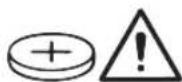
WARNING

Make sure that button cell batteries do not get into the hands of children. Button cell batteries are dangerous.
Button cell batteries must never be swallowed or inserted into any other body cavity. If you suspect that a button cell battery has been swallowed or inserted into another body cavity, seek medical attention immediately. Swallowing button cell batteries can lead to severe internal burns and death within 2 hours. ▶ When replacing the button cell battery, ensure proper replacement of the button cell battery. There is a risk of explosion. Use only the button cell batteries specified in these operating instructions. Do not use other button cell batteries or another power source. ▶ Do not attempt to recharge the button cell battery and do not short-circuit the button cell battery. The button cell battery may leak, explode, catch fire, and cause injury. ▶ Dispose of and remove discharged button cell batteries in accordance with regulations.
Discharged button cell batteries can leak and thus cause damage to the product or injure people.
Do not overheat the button battery and do not throw it into fire. The button battery may leak, explode, catch fire, and cause injury to persons. Do not damage the button battery and do not open the button battery. The button battery may leak, explode, catch fire, and cause injury to persons. ▶ Do not bring a damaged button battery into contact with water. The escaping lithium can react with water to produce hydrogen, which can lead to fire, explosion, or injury to persons. Do not use the measuring tool anymore when the button battery holder can no longer be closed properly and completely; remove the button battery and have the measuring tool repaired. Large temperature differences in a thermal image can result in even high temperatures being displayed in a color that corresponds to low temperatures. Contact with such a surface can lead to burns. Correct temperature measurements are only possible when the set emissivity and the emissivity of the object match. Objects can appear with a very high or very low temperature, which can potentially lead to danger upon contact. ▶ Do not point the measuring tool directly at the sun or at high-performance CO₂ lasers. This can lead to damage to the detector. ▶ Protect the measuring tool, especially the camera and infrared lens areas, from moisture, snow, dust, and contamination. The lens can be fogged or dirty and can distort the measurement results. Incorrect settings of the tool as well as other atmospheric influencing factors can lead to incorrect measurements. Objects can appear with a very high or very low temperature, which can potentially lead to danger upon contact.
Product description and performance
Please observe the illustrations at the front of the operating instructions.
Intended use
This thermal imaging camera is intended for non-contact measurement of surface temperatures.
The displayed thermal image shows the temperature distribution of the thermal camera's field of view and
126 | English
thus enables the representation of temperature deviations in different colors.
Thus, with proper application, surfaces and objects can be checked without contact for temperature differences and anomalies, making components and/or potential weak points visible, among other things:
- Thermal insulation and insulation (e.g., detection of thermal bridges),
- active heating and hot water pipes (e.g., underfloor heating) in floors and walls,
- overheated electrical components (e.g., fuses or terminals).
- Defective or damaged machine parts (e.g., overheating due to defective bearings).
The measuring tool is not suitable for measuring the temperature of gases.
The measuring tool must not be used for medical purposes.
For information on veterinary use, refer to www.bosch-professional.com/thermal.
The measuring tool is suitable for use both indoors and outdoors.
This product is a consumer laser product according to EN 50689.
The light of this measuring tool is intended for direct illumination of the measuring tool's work area for taking photos and does not serve as a permanent work lamp.
The laser dot must not be used as a laser pointer. It serves exclusively for marking the measuring surface.
Illustrated components
The numbering of the illustrated components refers to the illustration of the measuring tool on the graphics page.
(1) Protective cap (2) Laser beam exit opening (3) Optical lens (4) Work light (5) Infrared sensor (6) Measurement start/stop button (7) Battery compartment (8) Laser warning label
(9) Button battery holder (10) Screw for the button battery holder (11) Cover for the USB port and button battery holder (12) USB Type-C®a) port (13) Laser button (14) Rechargeable battery/battery adapter release button (15) Battery b) (16) USB Type-C®b) cable (17) Multi-function button (18) On/Off button/Back button (19) Display (20) Serial number (21) Battery adapter housing (22) Batteries b) (23) Battery adapter cap a) USB Type-C® and USB-C® are trademarks of USB Implementers Forum. b) Components shown or described are not included in the standard package.
Display elements
(a) Emissivity degree indicator (b) Reflected temperature indicator (c) Average temperature indicator (d) Memory full symbol (e) Work light symbol (f) Laser symbol (g) Charge status indicator (h) Maximum surface temperature indicator in the measuring area (i) Scale (j) Minimum surface temperature indicator in the measuring area (k) Temperature scale stabilization symbol (l) Cold spot indicator (example) (m) Crosshair with temperature indicator (n) Hot spot indicator (example) (o) Menu symbol
Technical data
| Κάμερα θερμικής απεικόνισης GTC 12V-450-13 | |
| Κωδικός αριθμός | 3 601 K83 900 |
| Ανάλυση του αισθητήρα υπερύθρων 256 × 192 px | |
| Θερμική ευαισθησίαA) | ≤ 50 mK |
| Φασματική περιοχή 8-14 μm | |
| Οπτικό πεδίο (FOV)A) | 55,6° × 42° |
Thermal imaging camera GTC 12V-450-13
| Χωρική ανάλυση (IFOV) 3,79 mrad | |
| Εστιακή απόστασηA) | ≥0,5 m |
| Εστίαση σταθερά | |
| Ρυθμός επανάληψης εικόνων θερμικής απεικόνισης ≤ 9 Hz | |
| Περιοχή μέτρησης επιφανειακής θερμοκρασίαςA) | -20 ... +450 °C |
| Ακρίβεια μέτρησης επιφανειακής θερμοκρασίαςA)(8)(C) | |
| >0 °C ... ≤ +100 °CD) | ±2 °C |
| >+100 °CE) | ±2 % |
| Ανάλυση θερμοκρασίας 0,1 °C | |
| Τύπος οθόνης TFT | |
| Μέγεθος οθόνης 2,8" | |
| Ανάλυση οθόνης 480 × 360 px | |
| Ανάλυση ενσωματωμένης οπτικής κάμερας 2 MP (640 × 480 px) | |
| Μορφότυπος αρχείου εικόνας .jpg | |
| Αποθηκευμένα στοιχεία ανά διαδικασία αποθήκευσης 1 θερμική απεικόνιση (στιγμιότυπο οθόνης),1 οπτική πραγματική εικόνα συμπερ. τιμών θερμοκρασίας (μεταδεδομένα) | |
| Μέγ. αριθμός εικόνων στην εσωτερική μνήμη αποθήκευσης εικόνων | 500 |
| Μέγ. ύψος χρήσης πάνω από το ύψος αναφοράς 2.000 m | |
| Βαθμός ρύπανσης κατά IEC 61010-1 2 | F) |
| Μέγιστη σχετική υγρασία αέραA) | 90 % |
| Κατηγορία λέιζερ 2 | |
| Τύπος λέιζερ < 1 mW, 645–660 nm | |
| Απόκλιση της ακτίνας λέιζερ 1,5 mrad (πλήρης γωνία) | |
| Παροχή ενέργειας | |
| – Επαναφορτιζόμενη μπαταρία (ιόντων λιθίου) | 12 V |
| – Μπαταρίες (αλκαλίου-μαγγανίου με προσαρμογέα μπαταρίας) | 4 × 1,5 V LR6 (AA) |
| – Επαναφορτιζόμενες μπαταρίες (NiMH με προσαρμογέα μπαταρίας) | 4 × 1,2 V HR6 (AA) |
| Διάρκεια λειτουργίαςB) | |
| – Επαναφορτιζόμενη μπαταρία (ιόντων λιθίου)H) | 8 h |
| – Μπαταρίες (αλκαλίου-μαγγανίου) | 4 h |
| Παροχή ενέργειας του χρόνου συστήματος | CR1225 (μπαταρία λιθίου 3 V) |
| Στάνταρ USB | 2.0 |
| Θύρα διεπαφής USB | USB Type-C® |
| ΒάροςC) | 0,354 kg |
| Διαστάσεις (μήκος × πλάτος × ύψος)K) | 89 × 79 × 209 mm |
| Βαθμός προστασίας (εκτός επαναφορτιζόμενης μπαταρίας/μπαταριών, σε όρθια θέση) | IP54 |
| Συνιστώμενη θερμοκρασία περιβάλλοντος κατά τη φόρτιση | 0 °C ... +35 °C |
| Επιτρεπόμενες θερμοκρασίες περιβάλλοντος | |
| – κατά τη λειτουργία | -10 °C ... +50 °C |
| – σε περίπτωση αποθήκευσης με επαναφορτιζόμενη μπαταρία | -20 °C ... +50 °C |
128 | Greek
Thermal imaging camera GTC 12V-450-13
| - σε περίπτωση αποθήκευσης χωρίς επαναφορτιζόμενη μπαταρία | -20 °C ... +70 °C |
| Συνιστώμενες επαναφορτιζόμενες μπαταρίες GBA 12V... | |
| Συνιστώμενοι φορτιστές GAL 12... | GAX 18... |
A) according to VDI 5585 standard (average value)
B) At an ambient temperature of 20–23 °C and an emissivity ≥ 0.95, measuring distance: 1 m, operating time: > 5 minutes, aperture 150 mm, with work light and laser switched off
C) Plus deviations depending on use (e.g., reflection, distance, ambient temperature)
D) Applies to the center; for all other pixels add ±1 °C
E) Applies to the center; for all other pixels add ±1 %
F) Only non-conductive contamination occurs, but occasional temporary conductivity caused by condensation is expected.
G) With work light switched off and medium screen brightness
H) Depends on the battery used
I) At an ambient temperature of 20-30 °C
J) Weight without rechargeable battery/battery adapter/batteries
K) With GBA 12V 2.0Ah or battery adapter
The serial number (20) on the type plate serves for unambiguous identification of the measuring instrument.
Power supply for the measuring tool
The measuring tool can be operated either with a Bosch lithium-ion battery, with commercially available batteries, or with commercially available rechargeable NiMH batteries.
Operation with rechargeable battery (see figure A)
Use only the chargers listed in the Technical data. Only these chargers are matched to the lithium-ion rechargeable battery used in the measuring tool.
Note: Due to international transport regulations, lithium-ion batteries are delivered partially charged. To ensure full battery power, charge the battery completely before first use.
To insert the charged rechargeable battery (15), push it into the battery slot (7) until it audibly locks into place. To remove the rechargeable battery (15), press the release buttons (14) and pull the rechargeable battery out of the battery slot (7). Do not use force.
Operation with batteries (see figure B)
For operation of the measuring tool, the use of alkaline-manganese batteries or rechargeable NiMH batteries is recommended.
The batteries are placed in the battery adapter.
The battery adapter is intended exclusively for use in the corresponding designated Bosch measuring tools and must not be used with power tools.
To insert the batteries, push the housing (21) of the battery adapter into the battery slot (7). Insert the batteries according to the illustration on the cover (23) into the housing. Push the cover over the housing until it audibly locks into place.
To remove the batteries (22), press the release buttons (14) on the cover (23) and remove the cover. Remove the batteries. To remove the housing (21) from the battery slot, grasp the housing and pull it out of the measuring tool while gently pressing the side wall. Replace all batteries or rechargeable batteries at the same time. The batteries must all be from the same manufacturer and have the same capacity.
Remove the batteries or rechargeable batteries from the measuring tool when you do not use it for an extended period. Batteries and rechargeable batteries may corrode if stored in the measuring tool for a long period.
Tips for optimal battery handling
Protect the battery from moisture and water.
Store the battery only in an area with a temperature range of –20 °C to 50 °C. Do not leave the battery in the car in summer, for example.
A significantly reduced operating time after charging means that the battery is exhausted and must be replaced.
Observe the disposal notes.
Operation
▶ Protect the measuring tool from moisture and direct solar radiation.
Do not expose the measuring tool to extreme temperatures or large temperature fluctuations. Do not leave it in the car for a long time, for example. In case of large temperature fluctuations, allow the measuring tool to acclimatize first before putting it into operation. The accuracy of the measuring tool can be impaired under extreme temperatures and/or strong temperature fluctuations. ▶ Ensure proper acclimatization of the measuring tool. In case of large temperature fluctuations, the acclimatization time can be up to 60 minutes. This can happen, for example, when you store the measuring tool in a cold car and then take a measurement in a warm building. Avoid strong impacts or dropping the measuring tool. After strong external influences and in case of unusual behavior in functionality, you must have the measuring tool checked by an authorized Bosch customer service center.
Start-up
During initial start-up
During the initial start-up of the measuring tool or after resetting to factory settings, certain basic settings must be made. Select the desired values by pressing the multi-function button (17) down, up, left, or right. Press the multi-function button (17) in the center to confirm your selection. Once you confirm the selection, the next setting appears on the display. The total number and the number of remaining settings are shown in the status bar at the top.
The following basic settings are available:
- <Language>
- <Date format>
- <Date>
- <Time format>
- <Time>
Switching On and Off
For measuring, open the protective cover (1). During work, ensure that the infrared sensor is not closed or covered.
To switch on the measuring tool, press the On/Off button (18). A start-up sequence appears on the display (19). After the start-up sequence, the measuring tool immediately begins measuring and continues without interruption until it is switched off.
Note: In the first few minutes, the measuring tool may recalibrate several times because the sensor temperature and the ambient temperature have not yet matched. The recalibration of the sensor enables an accurate measurement.
During this time, the temperature reading may be marked with \~. In the event of large fluctuations in ambient temperature, this effect is
intensified. Therefore, switch on the measuring tool as early as possible, ideally a few minutes before starting the measurement, so that it can stabilize thermally.
To switch off the measuring tool, press the On/Off button (18) for > 1 s. The measuring tool saves all settings and then switches off. Close the protective cover (1) for safe transport of the measuring tool.
In the main menu, you can select whether and after what time the measuring tool will switch off automatically (see "Main menu", page 132).
If the rechargeable battery or the measuring tool is outside the operating temperature specified in the technical data, the measuring tool switches off automatically after a brief warning (see "Errors – Causes and corrective measures", page 133). Allow the measuring tool to acclimatize and then switch it on again.
Navigating the Menus
Navigating the various menus of the measuring tool:
- Calling up the menu bars: Press the multi-function button (17) in the center or on the left. The menu bars on the right and left appear on the display, with the main menu highlighted.
- Scrolling/navigating in the main menu on the left menu bar: Press the multi-function button (17) up, down, left, or right.
- Switching between the left and right menu bars: Press the multi-function button (17) left or right.
- Confirming a selection/changing to the submenu: Press the multi-function button (17) in the center.
- To go back from a submenu to a higher-level menu: Press the Back key (18).
Preparing the measurement
Setting the emissivity for measuring surface temperature
The emissivity of an object depends on the material and the structure of its surface. It characterizes how much infrared thermal radiation the object emits compared to an ideal radiator (black body, emissivity ε = 1) and therefore ranges between 0 and 1.
To determine the surface temperature, the natural infrared thermal radiation emitted by the targeted object is measured without contact. For correct measurements, the emissivity set on the measuring instrument must be checked before each measurement and, if necessary, adjusted to the measurement object.
The emissivities preset on the measuring instrument are reference values.
You can select a preset emissivity or enter an exact numerical value. Set the desired emissivity via the menu “Measurement parameters” → “Emissivity” (see “Main menu”, page 132).
Correct temperature measurements are only possible when the set emissivity and the emissivity of the object match.
The lower the emissivity, the greater the influence of the reflected temperature on the measurement result. Therefore, when changing the emissivity, always adjust the reflected temperature. Set the reflected temperature via the menu “Measurement parameters” → “Reflected temperature” (see “Main menu”, page 132).
Any temperature differences displayed by the measuring instrument may be due to different temperatures and/or different emissivities. In the case of very different emissivities, the displayed temperature differences may deviate significantly from the actual ones.
If there are several measurement objects made of different materials or with different surface structures in the measurement area, the displayed temperature values are only valid for the objects that exactly match the set emissivity. For all other objects (with different emissivities), the displayed color differences can be used as an indication of the temperature relationships.
Notes on measurement conditions
Highly reflective or shiny surfaces (e.g., shiny tiles or polished metals) can distort or strongly negatively affect the displayed results. If necessary, cover the measurement surface with a dark, matte adhesive tape with good thermal conductivity. Allow the tape to reach the temperature of the surface.
Be careful with reflective surfaces to ensure a favorable measurement angle, so that any reflected thermal radiation from other objects does not distort the result. For example, when measuring perpendicularly from the front, the reflection of your body's heat can negatively affect the measurement. On a flat surface, the contours and temperature of your body (reflected value) may appear, which does not correspond to the actual temperature of the measured surface (emitted value or true surface value).
Measurement through transparent materials (e.g., glass or transparent synthetic materials) is not possible due to the operating principle. The measurement results are more reliable the better and more stable the measurement conditions are. In addition, not only large temperature fluctuations in the ambient conditions are important, but also large temperature fluctuations of the measured object can negatively affect accuracy. Infrared temperature measurement is adversely affected by smoke, steam/high air humidity, or dusty air.
Tips for better measurement accuracy:
- Get as close as possible to the measurement object to minimize interfering factors between you and the measurement surface. – Ventilate indoor spaces before measuring, especially when the air contains pollutants or a lot of steam. After ventilation, let the room acclimatize until it returns to its usual temperature.
Marking the measurement point
▶ Do not point the laser beam at people or animals and do not look into the laser beam yourself, even from a great distance.
The measuring tool is equipped with a laser for marking the measurement point.
Press and hold the laser button (13). The laser symbol (f) appears in the status line, and a red circle appears around the crosshair (m). The laser and crosshair overlap exactly at a distance of 1 m. When you release the laser button (13), the laser is deactivated.
Assigning temperatures using the scale
The scale (i) is displayed on the right side of the screen. The values at the top and bottom edges are based on the maximum temperature (h) or minimum temperature (j) detected in the thermal image. For the scale, 99.99% of all pixels are evaluated. The assignment of a color to a temperature value in the image is done with a uniform (linear) distribution.
With the help of the different shades, temperatures between these two limit values can thus be assigned. A temperature that lies exactly between the maximum and minimum values is thus assigned, for example, to the middle range of the scale's colors.
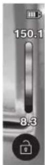
To verify the temperature of a specific area, move the measuring tool so that the crosshair with the temperature reading (m) points toward the desired point or area. In automatic adjustment, the entire color spectrum of the scale is always distributed linearly (= uniformly) across the entire measurement range between the maximum and minimum temperature.
The measuring tool displays all measured temperatures in the measurement range in relation to each other. If in an area, for example in a color display, heat appears bluish in the color palette, this means that the bluish areas belong to the colder measured values in the current measurement range. However, these areas can still be in a temperature range that, under certain conditions, could lead to injuries. Therefore, always pay attention to the displayed temperatures on the scale or directly at the crosshair.
Functions
Observe the information for navigating the various menus (see "Navigating the various menus", Page 129)

Illumination of the measuring object
The measuring tool is equipped with the work light (4). This is intended for direct illumination of the working area of the measuring tool for taking photos and is not intended as a permanent work lamp.
To switch the work light on/off, call up the left side bar. Scroll to the menu item / and confirm your selection. When the work light is switched on, this is displayed in the status bar.
The light switches off automatically after 2 minutes to avoid affecting the accuracy of the measurement.
You can set this automatic switch-off time in the <Instrument settings> menu.
Overlay of the thermal image and the real image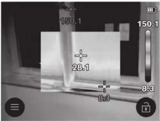
For better orientation (= spatial assignment of the displayed thermal image), an optical real image can additionally be used in the case of balanced temperature areas.
Note: The overlay of the real image and the thermal image matches exactly at a distance of 1 m. At distances deviating from the measuring object, a shift between the real image and the thermal image occurs due to the operating principle. This shift can be compensated for with special Bosch applications. Information on the applications and their compatibility can be found on the product page of the measuring tool or at www.bosch-professional.com/thermal.
Your measuring tool offers you the following options:
- 100% infrared image
Only the thermal image is displayed.

The displayed thermal image is placed slightly transparent over the real image. This allows objects to be recognized better.
To enable/disable this setting, call up the left side bar and scroll to the menu item <Optical Image On>/<Optical Image Off>. Confirm your selection by pressing the multi-function key (17) in the center.

Go to image
The displayed thermal image is cut out and the surrounding area is shown as a real image. This setting improves the local alignment of the measurement area. To enable/disable this setting, call up the left side bar and scroll to the menu item <Image-in-Image On>/<Image-in-Image Off>. Confirm your selection by pressing the multi-function key (17) in the center.
Adjusting the color display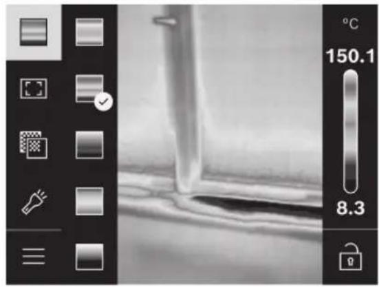
Depending on the measurement situation, different color palettes can facilitate the analysis of the thermal image and display objects or situations more clearly on the screen. The measured temperatures are not affected by this. Only the representation of the temperature values changes.
To change the color palette, call up the side bar and scroll to the menu item 'Color Palette'. Confirm your selection by pressing the multi-function key (17) in the center.

Freezing the scale
The adjustment of the color distribution in the thermal image is performed automatically, but it can be stabilized by pressing the multi-function key (17) to the right and then in the center. This makes it possible to compare thermal images taken under different temperature conditions (e.g., when checking multiple rooms for thermal bridges) or to hide an extremely cold or hot object in the thermal image that would otherwise distort it
(e.g., a radiator as a hot object when searching for thermal bridges).
To enable the scale again automatically, call up the right side bar and press the multi-function key (17) in the center. The temperatures now behave dynamically again and adapt to the measured minimum and maximum values.
Main menu
Call up the left side bar (see 'Navigating the menus', page 129). To go to the main menu, press the multi-function key (17) in the center.
- <Gallery> Under this menu item you can delete the stored images individually or all at once.
- Measurement parameters
• <Emissivity> (a)
For some of the most common materials, stored emissivity values are available for selection. To make searching easier, the values are grouped in the emissivity list. In the "Material list" menu, first select the appropriate category and then the appropriate material. If you know the exact emissivity of the object being measured, you can also set it as a numerical value in the "User-defined" menu.
- <Reflected temperature> (b)
Adjusting this parameter can improve the measurement result, especially for materials with low emissivity (= high reflection). In some situations (especially indoors), the reflected temperature corresponds to the ambient temperature. If there are objects with very different temperatures near strongly reflecting objects that could affect the measurement, you must adjust this value. To do so, press the multifunction key (17) left or right.
- <Temperature range>
To ensure high accuracy over the entire measurement range, measurements are taken in 2 temperature ranges. In <Auto> measurement mode, the measuring instrument automatically selects the appropriate temperature range based on the temperature distribution in the thermal image. It estimates how many measurement values are above a certain temperature threshold. If very small but very hot objects are to be measured, the low temperature range, which is unsuitable for high temperatures, may be selected. This can be recognized by the \~ symbol in the temperature display. In this case, switch to the <100 °C ... 450 °C> or <-20 °C ...
100 °C> measurement mode, in which the color distribution corresponds to the set temperature range. The setting is indicated on the scale with an up or down arrow.
- <Display settings>
• (m): /
The point is displayed centered in the thermal image and shows you the measured temperature value at that position.
- <Hot spot> (n): /
The hottest spot (= measurement pixel) is marked with a red crosshair in the thermal image. This makes it easier to search for critical points (e.g., a loose contact terminal in an electrical panel).
- <Cold spot> (I): /
The coldest spot (= measurement pixel) is marked with a blue crosshair in the thermal image. This makes it easier to search for critical points (e.g., non-tight spots on windows).
- <Temperature scale> (i): /
- <Average temperature> (c): /
The average temperature (c) is displayed at the top left of the thermal image (average temperature of all measured values in the thermal image). This can help you determine the reflected temperature.
- <Instrument settings>
- <Display brightness>
Under this menu item you can adjust the brightness of the display lighting.
- <Switch off LED after ...>
Under this menu item you can select the time interval for the automatic switch-off of the work light when no key is pressed.
- <Switch off instrument after ...>
Under this menu item you can select the time interval after which the measuring instrument switches off automatically when no key is pressed. You can also disable the automatic switch-off by selecting the <Never> setting.
- <Date and time>
In this submenu, in addition to setting the time and date, you can also change their respective formats.
- <Language>
Under this menu item you can select the language used for the display.
- <Reset to factory settings>
Under this menu item you can reset the measuring tool to factory settings and permanently delete all data. Under certain conditions, this may take several minutes. Press the multifunction button (17) on the right to delete all files, or the multifunction button (17) on the left to cancel the process.
- <Information>
Under this menu item you can access information about the measuring tool. There you will find the serial number of the measuring tool and the installed software version. Additionally, you can find further information about the measuring tool as well as a software update.
To exit any menu and return to the standard display screen, you can also press the measurement button (6).
Software update of the measuring tool
If necessary, you can update the software of the measuring tool via the USB Type-C® interface port. Information about this can be found at: www.bosch-professional.com/thermal-update.
Documentation of measurement results
Saving measurement results
Immediately after activation, the measuring tool starts measuring and continues without interruption until it is deactivated.
To save an image, point the camera at the desired measurement object and press the measurement button (6). The image is saved to the internal memory of the measuring tool. The measurement "freezes" and is displayed on the screen. This allows careful observation of the image and subsequent adjustment (e.g., of the color palette). If you do not want to save the frozen image, start the measurement function again with the measurement button (6). If you want to save the image to the internal memory of the measuring tool, press the multifunction button (17) in the center.
Calling up saved images
To call up saved thermal images, proceed as follows:
- After saving, press the multifunction button (17) in the center again directly. The preview of the last saved photo is now displayed on the screen.
- Alternatively, you can call up the saved photos under the menu item <Gallery>.
- To switch between the saved thermal images, press the multifunction button (17) on the right or left.
In addition to the thermal image, the visual image was also saved. To call it up, press the multifunction button (17) up or down.
After 5 s, the measuring instrument switches to the full image view. In the full image view, the title bar display is hidden so that you can observe all the details of the thermal image.
By pressing the multifunction button (17) up and down, you can change views.
Deleting saved images
To delete individual or all thermal images, press the multifunction button (17) in the center. A submenu opens.
- Here you can choose whether you want to delete only this image or all images. Confirm the
selection with the multifunction button (17) in the center. In the <Delete images> option, you can choose between <Delete all> and <Cancel>. Confirm the selection with the multifunction button (17) in the center.
- In this submenu, you can also view information about the emissivity and the reflected temperature.
Data segments of the images remain in memory and could be reconstructed. For final deletion, select <Instrument settings> → <Factory reset> in the main menu.
Data transfer
Data transfer via USB interface port
Open the cover (11) of the USB Type-C® socket. Connect the USB Type-C® socket (12) of the switched-off measuring instrument to your computer via the USB Type-C® cable (16).
Switch on the measuring instrument only with the On/Off button (18).
Open the file browser on your computer and select the drive GTC_450. The stored files can be copied, moved to your computer, or deleted from the internal memory of the measuring instrument.
Once you have completed the desired process, disconnect the drive properly and then switch off the measuring instrument again with the On/Off button (18).
Caution: Always disconnect the device from your operating system first (device removal), otherwise the internal memory of the measuring tool may be damaged.
Remove the USB Type-C® cable and close the cover (11).
Always keep the USB interface cover closed to prevent dust or water from entering the housing.
Note: Connect the measuring tool via USB exclusively to a computer (PC). Connecting to other devices may damage the measuring tool.
Note: The USB Type-C® interface is intended solely for data transfer. Batteries and rechargeable batteries cannot be charged via this port.
Post-processing of thermal images
You can post-process the saved thermal images with special Bosch apps. Information about the apps and their compatibility can be found on the product page of the measuring tool or at www.bosch-professional.com/thermal.
Errors – Causes and corrective measures
In the event of a malfunction, the measuring tool performs a restart and can then be used again. Otherwise, the following overview will help you with persistent error messages.
Error Cause Remedy
| Το όργανο μέτρησης δεν μπορεί να ενεργοποιηθεί. | Επαναφορτιζόμενη μπαταρία/μπαταρίες άδεια | Φορτίστε την επαναφορτιζόμενη μπαταρία ή αλλάξτε τις μπαταρίες. | |
 | Σφάλμα επαναφορτιζόμενης μπαταρίας/μπαταριών | Αλλάξτε την επαναφορτιζόμενη μπαταρία ή τις μπαταρίες. | |
 | Επαναφορτιζόμενη μπαταρία/μπαταρίες πολύ ζεστή ή πολύ κρύα | Φορτίστε την επαναφορτιζόμενη μπαταρία να εγκλιματιστεί ή αλλάξτε την επαναφορτιζόμενη μπαταρία ή τις μπαταρίες. | |
 | Όργανο μέτρησης πολύ ζεστό ή πολύ κρύο | Αφήστε το όργανο μέτρησης να εγκλιματιστεί. | |
 | Σύνδεση USB ή καλώδιο USB ελαττωματικό | Ελέγξτε, εάν το όργανο μέτρησης μπορεί να συνδεθεί με έναν άλλο υπολογιστή. Εάν όχι, στείλτε το όργανο μέτρησης σε ένα εξουσιοδοτημένο/συμβεβλημένο Bosch κέντρο εξυπηρέτησης πελατών. | |
| Το όργανο μέτρησης δεν μπορεί να συνδεθεί με έναν υπολογιστή. | Υπόδειξη:Χρησιμοποιείτε πάντοτε το καλώδιο USB από τα υλικά παράδοσης. | ||
| Μπαταρία τύπου κουμπιού άδεια | Αντικαταστήστε την μπαταρία τύπου κουμπιού (βλέπε «Αλλαγή της μπαταρίας τύπου κουμπιού (βλέπε εικόνα C)», Σελίδα 135).Επιβεβαιώστε την αλλαγή με «ΟΚ», πατώντας το πολυλειπουργικό πλήκτρο (17) στο κέντρο. | ||
Interpretation of definitions
Further information can be found at www.bosch-professional.com/thermal.
Infrared thermal radiation
Infrared thermal radiation is electromagnetic radiation emitted by any body above 0 Kelvin (-273 °C). The amount of radiation depends on the temperature and the emissivity of the body.
Emissivity
The emissivity of an object depends on the material and structure of its surface. It characterizes how much infrared thermal radiation the object emits compared to an ideal radiator (black body, emissivity ε = 1) and therefore ranges between 0 and 1.
Thermal bridge
A thermal bridge is a location in the exterior wall of a building where, due to construction, a locally increased heat loss occurs.
Thermal bridges can lead to an increased risk of mold.
Reflected temperature / Reflectivity of an object
The reflected temperature is the thermal radiation that does not originate from the object itself. Depending on the structure
and material, environmental radiation is reflected onto the object to be measured, thus altering the true temperature result.
Object distance
The distance between the measurement object and the measuring instrument affects the detected surface area per pixel. As the object distance increases, you can detect larger and larger objects.
| Απόσταση (m) Μέγεθος υπέρυ-θρου πίξελ (mm) | Περιοχή υπερύθρων πλάτος × ύψος (m) |
| 0,30 1,14 ~ 0,29 × 0,22 | |
| 0,55 2,08 ~ 0,53 × 0,40 | |
| 1,00 3,79 ~ 0,97 × 0,73 | |
| 2,00 7,58 ~ 1,94 × 1,46 | |
| 5,00 18,95 ~ 4,85 × 3,64 |
Maintenance and service
Maintenance and cleaning
Store and transport the measuring instrument only in a suitable container, such as the original packaging.
Always keep the measuring instrument clean. A dirty infrared sensor (5) can affect measurement accuracy.
Make sure no liquids enter the measuring tool when cleaning it.
Do not attempt to remove dirt from the infrared sensor (5), the camera (3), the work light (4), or the laser beam exit opening (2) with pointed objects. Do not wipe over the infrared sensor and the camera (risk of scratching).
Clean regularly, especially the surfaces near the laser beam exit, and make sure no lint accumulates.
If you want a new calibration of the measuring tool, contact an authorized/contracted Bosch customer service center.
In case of repair, send the measuring tool in its original packaging.
There are no user-serviceable parts inside the measuring tool. Opening the housing may damage the measuring tool.
Changing the button battery (see figure P)
Open the cover (11).
Unscrew the screw (10) on the button battery holder. Pull the button battery holder (9) out of the measuring tool. Replace the button battery. After inserting the button battery holder, screw the screw (10) back in firmly.
Customer service and application advice
Customer service answers your questions about repair and maintenance of your product as well as spare parts. Detailed drawings and information about spare parts can be found at:
www.bosch-pt.com
The Bosch application advice team will be happy to answer your questions about our products and their accessories.
For all questions and spare parts orders, always quote the 10-digit product code number from the type plate of the product.
Greece
Robert Bosch A.E.
Erchias 37
19400 Koropi - Athens
Tel.: 210 5701258
Fax: 210 5701283
Email: pt@gr.bosch.com
www.bosch.com
www.bosch-pt.gr
Further service addresses can be found here:
www.bosch-pt.com/serviceaddresses
Transport
The recommended lithium-ion batteries are subject to the requirements of the legislation on dangerous products. The batteries can be transported by road by the user without further conditions.
In case of shipment by third parties (e.g., by air or by freight company), the special requirements regarding packaging and labeling must be observed. When preparing the item to be shipped, the advice of a specialist for dangerous products must definitely be sought.
Only send rechargeable batteries when the housing is intact. Tape over the bare contacts with adhesive tape and pack the battery in such a way that it cannot move around inside the packaging.
Please also observe any further national regulations.
Disposal

Measuring tools, rechargeable batteries/batteries, accessories, and packaging must be recycled in an environmentally friendly manner.
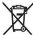
Do not dispose of measuring tools and batteries in household waste!
For EU countries only:
Unusable measuring tools and defective or used rechargeable batteries/batteries must be disposed of separately. Use the designated collection systems.
If old electrical and electronic devices are disposed of improperly, they can have harmful effects on the environment and human health due to the possible presence of hazardous substances.
Rechargeable batteries/Batteries:
Li-Ion:
Please observe the instructions in the Transport section (see "Transport", page 135).
Turkish
Safety instructions

All safety instructions and warnings must be read to work with the measuring tool safely and without danger. If the measuring tool is not used in accordance with these safety instructions,
the protective equipment integrated in the measuring tool may be impaired. Never make the warning labels on the measuring tool unrecognizable. KEEP THESE INSTRUCTIONS IN A SAFE PLACE AND
HAND THEM OVER TO THE NEXT USER OF THE MEASURING TOOL.
Caution – The use of equipment or adjustment devices other than those mentioned here, or the use of different procedures, may result in hazardous radiation exposure. ▶ This measuring tool is delivered with a laser warning label (shown on the graphics page with the picture of the measuring tool). ▶ If the text on the laser warning label is not in your language, stick the laser warning label in your language, which is included with the tool, over the existing label before first use.

Do not point the laser beam at other people or animals, and do not look directly into the laser beam, whether direct or reflected. Otherwise, you may dazzle others, cause accidents, or damage your eyes.
▶ If the laser beam hits your eye, consciously close your eyes and immediately turn your head away. ▶ Do not make any modifications to the laser equipment.
Do not use the laser viewing glasses (accessory) as protective goggles. The laser viewing glasses make the laser beam easier to see, but they do not provide protection against the laser beam.
Do not use the laser viewing glasses (accessory) as sunglasses or in traffic. The laser viewing glasses do not provide complete protection against infrared radiation and reduce color perception.
Have the measuring tool serviced only by qualified specialist personnel and only with original spare parts. This ensures the safety of the measuring tool.
Do not allow children to use the laser measuring tool without supervision. You could unintentionally dazzle yourself or others.
Do not work with the measuring tool in explosive atmospheres where flammable liquids, gases, or dusts are present. The measuring tool may create sparks that could ignite dust or fumes.
Do not replace or open the battery. There is a risk of short circuit.
If the battery is damaged or used improperly, vapor may escape. The battery can catch fire or explode. Ventilate the area and seek medical attention if you experience any discomfort. Vapors from the battery can irritate the respiratory tract.
Improper use or a damaged battery can cause flammable liquid to leak from the battery. Avoid contact with this liquid. If contact occurs accidentally, rinse the affected area with water. If the liquid gets into your eyes, seek medical attention. Leaking battery fluid can cause skin irritation and burns.
Sharp objects such as nails or screwdrivers, or external force, can damage the battery. An internal short circuit can occur, and the battery can catch fire, emit smoke, explode, or overheat. Keep the battery away from paper clips, coins, keys, nails, screws, or other small metal objects that could bridge the contacts when not in use. A short circuit between battery contacts can cause burns or fire. Use the battery only in products from the manufacturer. Only this way can the battery be protected against dangerous overloading. Charge the batteries only in chargers recommended by the manufacturer. A charger that is suitable for one type of battery may create a fire risk when used with another battery.

Protect the battery from heat, direct sunlight, fire, dirt, water, and moisture. There is a risk of explosion and short circuit.
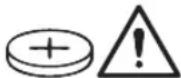
WARNING

Take precautions to keep button cells away from children. Button cells are dangerous.
Button batteries must never be swallowed or inserted into any other body opening. If you suspect that a button battery has been swallowed or has entered the body through another opening, seek medical attention immediately. Swallowing a button battery can cause internal burns and death within 2 hours. When replacing the button battery, ensure that it is replaced properly. There is a risk of explosion. ▶ Only use the button batteries specified in this instruction manual. Do not use different button batteries or any other power source. Do not attempt to recharge the button battery and do not short-circuit it. The button battery may leak, explode, catch fire, and cause injury. ▶ Remove the depleted button battery and dispose of it properly. Depleted button batteries may leak and damage the product or cause injury. Do not overheat the button battery or throw it into fire. The button battery may leak, explode, catch fire, and cause injury. Do not damage or disassemble the button battery. The button battery may leak, explode, catch fire, and cause injury. ▶ Do not bring a damaged button battery into contact with water. If leaking lithium comes into contact with water, hydrogen gas may be released, which can lead to fire, explosion, or injury.
If the button battery holder assembly can no longer be closed properly and completely, stop using the measuring tool, remove the button battery, and have the measuring tool repaired. Large temperature differences in a thermal image can cause even high temperatures to be displayed in a color associated with low temperatures. Contact with such a surface can cause burns. ▶ Accurate temperature readings are only possible if the set emissivity matches the emissivity of the object. Objects are displayed with a temperature that is too high or too low; contact can be dangerous. - Do not point the measuring tool directly at the sun or at a high-performance CO₂ laser. This can damage the detector. Protect the measuring tool, especially the camera and infrared lens area, from moisture, dirt, dust, and grime. The detection lens may fog up or become dirty and impair measurement results. Incorrect tool settings and other weather-related influencing factors can lead to incorrect measurements. Objects are displayed with a temperature that is too high or too low; contact can be dangerous.
Product and performance description
Please note the illustrations at the front of the instruction manual.
Intended use
This thermal camera is designed for non-contact measurement of surface temperatures.
The displayed thermal image shows the temperature distribution of the thermal camera's field of view, thus enabling temperature deviations to be displayed in different colors.
Thus, surfaces and objects can be inspected non-contact, in a technically correct manner, for temperature differences or anomalies, in order to make visible the components and/or possible weak points, examples of which you can find in the list below. These components or possible weak points include the following:
- Thermal insulation and insulation (e.g., detection of thermal bridges),
- Active heating and hot water pipes in floors and walls (e.g., underfloor heating systems),
- Overheated electrical components (e.g., fuses or terminals),
- Faulty or damaged machine parts (e.g., overheating due to defective ball bearings).
The measuring tool is not suitable for measuring the temperature of gases. The measuring tool must not be used for human medical purposes.
For information on use in veterinary medicine, please visit www.bosch-professional.com/thermal.
This measuring tool is suitable for use indoors and outdoors.
This product is a consumer laser product in accordance with EN 50689.
The light of this measuring tool is designed to illuminate the working area of the measuring tool directly for image capture; it is not intended for use as a permanent work light.
The laser point must not be used as a laser pointer. It is only used to mark the measuring area.
Displayed components
The numbers of the components shown in the figure correspond to the numbers in the illustration of the measuring tool on the graphics page.
(1) Protective flap (2) Laser beam outlet (3) Visual camera (4) Work light (5) Infrared sensor (6) Pause/start measurement button (7) Battery compartment (8) Laser warning label (9) Button battery holder assembly
(10) Button battery holder assembly screw (11) USB port and cover for button battery holder assembly (12) USB Type-C® socket a) (13) Laser button (14) Battery/power adapter release button (15) Battery b) (16) USB Type-C® cable b) (17) Multi-function button (18) On/Off button/Back button (19) Display (20) Serial number (21) Power adapter housing (22) Batteries b) (23) Power adapter cover a) USB Type-C® and USB-C® are trademarks of USB Implementers Forum. b) Accessories shown or described are not included in the standard delivery.
Display elements
(a) Emissivity indicator (b) Reflected temperature indicator (c) Average temperature indicator (d) Memory full symbol (e) Work light symbol (f) Laser symbol (g) Charge status indicator (h) Maximum surface temperature indicator in measurement range (i) Scale (j) Minimum surface temperature indicator in measurement range
138 | Turkish
(k) Temperature scale symbol lock
(n) Hot spot indicator (example)
(I) Cold spot indicator (example)
(o) Menu symbol
(m) Crosshair temperature indicator
Technical data
| Termal kamera GTC 12V-450-13 | |
| Sipariş numarası | 3 601 K83 900 |
| Kızılötesi sensörü çözünürlüğü 256 × 192 piksel | |
| Termal hassasiyetA) | ≤ 50 mK |
| Spektral alan 8–14 μm | |
| Görüş alanı (FOV)A) | 55,6° × 42° |
| Uzamsal çözünürlük (IFOV) 3,79 mrad | |
| Odak uzaklığıA) | ≥ 0,5 m |
| Odak Sabit | |
| Termal görüntü yineleme hızı ≤ 9 Hz | |
| Yüzey sıcaklığı ölçüm aralığıA) | -20 ... +450 °C |
| Ölçüm hassasiyeti yüzey sıcaklığıA|B|C) | |
| >0 °C ... ≤ +100 °CD) | ±2 °C |
| > +100 °CE) | ±%2 |
| Sıcaklık çözünürlüğü 0,1 °C | |
| Ekran tipi TFT | |
| Ekran boyutu 2,8" | |
| Ekran çözünürlüğü 480 × 360 piksel | |
| Entegre görsel kamera çözünürlüğü 2 MP (640 × 480 piksel) | |
| Resim formatı .jpg | |
| Kaydetme işlemi başına kaydedilen öğeler 1 × termal görüntü (ekran görüntüsü),sicaklık değerlerini (meta veriler) içeren 1 × görsel gerçekgörüntü | |
| Maks. dahili görüntü hafizasındaki görüntü sayısı 500 | |
| Referans yükseklik üzerinde maks. uygulama yüksekliği 2000 m | |
| IEC 61010-1 uyarınca kirlenme derecesi 2 | F) |
| Maks. bağlı nemA) | %90 |
| Lazer sınıfı | 2 |
| Lazer tipi | < 1 mW, 645–660 nm |
| Lazer ışını sapması | 1,5 mrad (tam açı) |
| Enerji kaynağı | |
| - Akü (Lityum İyon) | 12 V |
| - Piller (pil adaptörlü alkalin manganez) | 4 × 1,5 V LR6 (AA) |
| - Aküler (NiMH, pil adaptörü ile) 4 × 1,2 V HR6 (AA) | |
| İşletme süresiG) | |
| - Akü (Lityum İyon)H) | 8 sa |
| - Piller (alkali mangan) | 4 sa |
| Enerji kaynağı sistem süresi | CR1225 (3 V Lityum pil) |
| USB standardı | 2.0 |
| USB arabirimi | USB Type-C® |
| AğırlıkJ) | 0,354 kg |
1609 92A 9ZG | (14.01.2025)
Bosch Power Tools
Thermal camera GTC 12V-450-13
| Ölçüleri (uzunluk × genişlik × yükseklik) K) | 89 × 79 × 209 mm |
| Koruma sınıfı (dik konumdaki akü/pil hariç) IP54 | |
| Şarj sırasında önerilen ortam sıcaklığı 0 °C ... +35 °C | |
| İzin verilen ortam sıcaklığı | |
| - İşletimde -10 °C ... +50 °C | |
| - Akü ile birlikte depolandığında -20 °C ... +50 °C | |
| - Akü olmadan depolandığında -20 °C ... +70 °C | |
| Tavsiye edilen aküler GBA 12V... | |
| Önerilen şarj cihazları GAL 12... | GAX 18... |
A) According to VDI 5585 standard (average value) B) At 20–23 °C ambient temperature and ≥ 0.95 emissivity, measurement distance: 1 m, operating time: > 5 min, 150 mm aperture, with work light and laser off C) With addition of application-related deviations (e.g., reflection, distance, ambient temperature) D) Applies to center point, for all other pixels additionally ±1 °C E) Applies to center point, for all other pixels additionally ±1% F) Although conductivity may occasionally be visible due to condensation, only non-conductive contamination occurs. G) With work light off and medium screen brightness H) Depending on battery used 1) At 20-30°C ambient temperature J) Weight excluding battery/battery adapter/batteries K) With GBA 12V 2.0Ah or battery adapter The serial number (20) on the type label enables identification of the measuring tool.
Measuring device power supply
The measuring tool can be operated with a Bosch lithium-ion battery, commercially available batteries, or commercially available NiMH batteries.
Working with the battery (see Figure A)
▶ Only use the chargers specified in the technical data section. Only these chargers are designed for the lithium-ion batteries that can be used in your measuring tool.
Note: Lithium-ion batteries are delivered partially charged in accordance with international shipping regulations. To achieve full performance from the battery, fully charge the battery before first use.
To insert the charged battery (15), push it into the battery mount (7) until it clicks into place.
To remove the battery (15), press the corresponding release buttons (14) and pull the battery out of the battery mount (7). Do not use force when doing this.
Working with batteries (see Figure B)
It is recommended to use alkaline-manganese batteries or NiMH rechargeable batteries to operate the measuring tool.
The batteries are inserted into the battery adapter.
- The battery adapter is only designed for the Bosch measuring tools for which it is intended and cannot be used with power tools.
To insert the batteries, push the battery adapter housing (21) into the battery mount (7). Insert the batteries into the housing according to the figure on the screw cap (23).
Push the screw cap onto the housing until it clicks into place.
To remove the batteries (22), press the release buttons (14) on the screw cap (23) and remove the screw cap. Remove the batteries. To remove the housing (21) from the battery mount, hold the housing and pull it out from the side of the measuring tool with light pressure.
Always replace all batteries or rechargeable batteries at the same time. Only use batteries or rechargeable batteries from the same manufacturer or with the same capacity.
Remove batteries or rechargeable batteries from the measuring tool if they will not be used for an extended period. Batteries and rechargeable batteries may corrode if left in the measuring tool for a long time.
Instructions for optimal battery use
Protect the battery from moisture and water.
Store the battery only at temperatures between -20 °C and 50 °C. For example, do not leave the battery in the car during summer.
If after charging the battery can only be used for a very short time, it means the battery has reached the end of its life and needs to be replaced.
Follow the instructions regarding disposal.
Operation
Protect the measuring device from moisture and direct sunlight.
- Do not expose the measuring tool to extreme temperatures or temperature fluctuations. For example, do not leave it in a car for a long time. After large temperature fluctuations, allow the measuring tool to acclimate to the ambient temperature before switching it on again. Extreme temperatures or temperature fluctuations can adversely affect the accuracy of the measuring tool. ▶ Ensure that the measuring tool fully acclimates to the ambient air. In case of extreme temperature fluctuations, acclimatization can take up to 60 minutes. This can happen, for example, when you want to take measurements in a warm building after storing the measuring tool in a cold car. Ensure that the measuring tool is not subjected to severe impacts or drops. If the tool has been subjected to severe external influences or shows visible signs of malfunction, it must be sent to an authorized Bosch customer service center for inspection.
Starting Operation
Initial Operation
After resetting the measuring tool to factory settings or when switching it on for the first time, some basic settings need to be made. Use the multi-function button (17) to select the desired values by pressing down, up, left, or right. Press the center of the multi-function button (17) to confirm your selection. As soon as you confirm your selection, the next setting will appear on the display. The total number and the number of remaining settings are shown in the status indicator at the top.
The following basic settings are available:
Switching On/Off
To take measurements, open the protective cap (1). While working, ensure that the infrared sensor is not covered or obstructed.
To switch on the measuring tool, press the on/off button (18). The start process appears on the display (19). After the start process, the measuring tool immediately begins measuring and continues until it is switched off.
Note: During the first few minutes, the sensor and ambient temperature have not yet equalized, so the measuring tool may calibrate itself more frequently. The renewed equalization of the sensor enables precise measurement.
During this time, the temperature display may be marked with ~. This effect is even more pronounced with strong fluctuations in ambient temperature. Therefore, to allow the measuring tool to thermally stabilize, turn it on a few minutes before starting the measurement.
To switch off the measuring tool, press the on/off button (18)
for 1 second. The measuring tool saves all settings and
then switches off. Close the protective cap (1) to safely transport the measuring tool.
In the main menu, you can select whether the measuring tool switches off automatically and, if so, after what period of time (see "Main menu", page 142).
To save energy, only switch on the measuring tool when you are using it.
If the battery or the measuring tool is outside the operating temperature specified in the technical data, the measuring tool switches off automatically after a brief warning (see "Error – Causes and Solutions", page 144). Wait for the temperature of the measuring tool to stabilize and then switch it on again.
Navigating in the various menus
Navigating in the various menus of the measuring tool:
- Display the menu bars: Press the middle or left multi-function button (17). The right and left menu bars appear on the display, with the main menu in the foreground.
- Scroll in the left menu bar/navigate in the main menu: Press up, down, left, or right on the multi-function button (17).
- Switch to the left or right menu bar: Press left or right on the multi-function button (17). – Confirm the selection/enter a submenu: Press the middle multi-function button (17).
- Return from a submenu to a higher-level menu: Press the back button (18).
Preparation for measuring
Setting the emission degree for surface temperature measurements
The emissivity of an object depends on the material and the structure of the surface. It indicates how much infrared heat radiation an object emits compared to an ideal heat radiator (black body, emissivity € = 1) and is therefore a value between 0 and 1.
To determine the surface temperature, the natural infrared heat radiation emitted by the target object is measured without contact. For accurate measurements, the emissivity set on the measuring instrument must be checked before each measurement and, if necessary, adjusted to the measurement object. The emissivity values preset on the measuring instrument are reference values.
You can select one of the preset emissivity values or enter a more precise numerical value. Set the preset emissivity via the <Measurement parameters> menu (see "Main menu", page 142).
▶ Accurate temperature readings are only possible if the set emissivity matches the emissivity of the object.
The lower the emissivity, the greater the influence of the reflected temperature on the measurement result. Therefore, always adjust the reflected temperature when changing the emissivity. Set the reflected temperature via the <Measurement
parameters> menu (see "Main menu", page 142).
The temperature differences displayed by the measuring instrument may be due to different temperatures and/or different emissivities. With very different emissivities, the displayed temperature differences can differ significantly from the actual ones.
If there are multiple measurement objects made of different materials or with different structures within the measurement range, the displayed temperature values are only correct for objects that match the set emissivity. For all other objects with different emissivities, the displayed color differences can be used to indicate temperature relationships.
Notes on measurement conditions
Highly reflective or shiny surfaces (e.g., glossy tiles or bare metals) can significantly distort or corrupt the displayed results. In such cases, cover the measurement area with dark adhesive tape with good thermal conductivity. Wait a short time for the tape to adhere to the surface. To prevent reflected heat radiation from other objects from distorting the result, pay attention to a suitable measurement angle on reflective surfaces. For example, when measuring vertically from the front, the reflection of your body heat can adversely affect the measurement. On a flat surface, the outline and temperature of your body may be displayed (reflected value) in such a way that it does not correspond to the actual temperature of the measured surface (emitted value or actual value of the surface).
Measuring through transparent materials (e.g., glass or transparent plastics) is not possible in principle.
The better and more stable the measurement conditions, the more precise and reliable the measurement results will be. Here, not only strong temperature fluctuations in the ambient conditions, but also strong fluctuations in the temperatures of the measured object can adversely affect precision. Infrared temperature measurement is adversely affected by smoke, steam/high humidity, or dusty air.
Tips for more precise measurements:
- Approach the measurement object as closely as possible to minimize factors that could have a negative impact between the measurement area and you.
- Before measuring, ventilate the room you are in, especially if the air is dirty and steamy. After ventilating the room, wait for it to cool down until it returns to its normal temperature.
Marking the measurement point
▶ Do not point the laser beam at other people or animals, and do not look into the laser beam, even from a distance.
The measuring tool is equipped with a laser for marking the measurement point.
Press and hold the laser button (13). The laser symbol (f) is displayed in the status indicator, and a red circle appears around the crosshair (m). The laser and crosshair overlap
exactly at a distance of 1 m. When you release the laser button (13), the laser turns off.
Determining temperatures using the scale
The scale (i) is displayed on the right side of the screen. The values at the upper and lower ends depend on the maximum (h) or minimum temperature (j) found in the thermal image. For the scale, 99.99% of the total pixels are evaluated. The assignment of a color to a temperature value in the image is distributed evenly (linearly).
With the help of different color shades, temperatures within these two limit values can be assigned. For example, a temperature exactly in the middle of the maximum and minimum values is assigned to the middle color range of the scale.
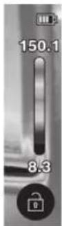
To determine the temperature of a specific area, move the measuring tool so that the crosshair temperature indicator (m) is directed at the desired point or area. In automatic adjustment, the color spectrum of the scale is always distributed linearly (= evenly) over the entire measurement range of the maximum or minimum temperatures.
The measuring tool displays all temperatures measured within the measurement range in colors proportional to each other. If heat is displayed in one area, e.g., with a bluish color in the color palette, this means that the bluish areas correspond to the cold measurement values in the current measurement range. However, these areas may still be in a temperature range that could cause injuries. Therefore, always pay attention to the temperatures displayed on the scale or directly on the crosshair.
Functions
Please pay attention to the navigation information in the various menus (see "Navigating in the various menus", page 140).

Illumination of the measured object
The measuring tool is equipped with a work light (4). It is designed to illuminate the immediate work area for taking photos and is not intended as a permanent work light.
To switch the work light on/off, bring up the left-hand sidebar. Navigate to the menu item / and confirm your selection. If the work light is on, this is displayed in the status indicator.
To avoid affecting the accuracy of the measurement, the light automatically switches off after 2 minutes.
You can adjust the automatic switch-off time in the following menu.
Overlaying thermal and real images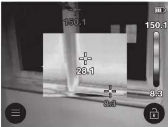
For better orientation (= spatial assignment of the displayed thermal image), a real visual image can also be added when the temperature ranges are balanced.
Note: The overlay of the real and thermal images coincides exactly at a distance of 1 m. If the distances to the object to be measured differ, the real image and the thermal image will not overlap exactly. This offset can be compensated for with special Bosch applications. Information about the applications and their compatibility can be found on the product page of the measuring tool or at www.bosch-professional.com/thermal.
The measuring tool offers you the following options:
100% infrared image
Only the thermal image is displayed.

- Transparency
The displayed thermal image is placed transparently over the real image. This allows for better recognition of objects.
To enable/disable the setting, bring up the left sidebar and navigate to the menu item / .
Confirm your selection by pressing the central multi-function button (17).

- Picture-in-picture
The displayed thermal image is cropped and the area around it is shown as a real image. This setting improves the local assignment of the measurement range.
To enable/disable the setting, bring up the left sidebar and navigate to the menu item
/ . Confirm your selection by pressing the central multi-function button (17).
Adaptation of the color image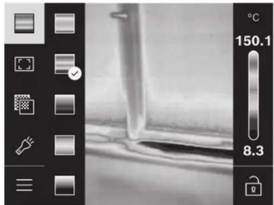
Depending on the measurement situation, different color palettes can facilitate the analysis of thermal images and allow objects or subjects to be displayed more prominently on the screen. The measured temperatures are not affected by this. Only the display of the temperature values changes.
To change the color palette, bring up the sidebar and go to the "Color palette" menu item. Confirm your selection by pressing the central multi-function button (17).

Fixing the scale
The color distribution in the thermal image is adjusted automatically, but can also be fixed by pressing the right and then the central multi-function button (17). This enables the comparability of thermal images taken under different temperature conditions (e.g., when checking several rooms for thermal bridges) or the hiding of an extremely cold or hot object in the thermal image (e.g., a radiator as a hot object when searching for thermal bridges) that would otherwise cause distortion.
To return the scaling to automatic mode, bring up the sidebar on the right and press the central multi-function button (17). The temperatures now behave dynamically again and adapt to the measured minimum and maximum values.
Main menu
Bring up the left sidebar (see "Navigating in the various menus", page 140). Press the central multi-function button (17) to access the main menu.
- Under this menu item, you can delete saved images individually or all at once.
- <Measurement parameters>
- (a)
Registered emissivity levels for some of the most commonly used materials are available for selection. To make searching easier, the values are compiled in the emissivity level catalog. First select the appropriate category in the menu item, then the appropriate material. If you know the exact emissivity level of your measurement object, you can also set it
as a numerical value in the menu item.
• (b)
Setting this parameter can improve measurement results, especially for materials with low emissivity (= high reflectivity). In some cases (especially indoors), the reflected temperature corresponds to the ambient temperature. If objects with very different temperatures near highly reflective objects affect the measurement, you need to adjust this value. To do this, press the multifunction button on the left or right (17).
-
To ensure high accuracy over the entire measurement range, measurements are taken in two temperature ranges. In the measurement function, the measuring instrument automatically selects the appropriate temperature range based on the temperature distribution in the thermal image. It evaluates how many of the measured values are above a certain temperature threshold. If very small but hot objects are to be measured, a low temperature range that is not suitable for high temperatures may be selected. This can be recognized by the \~ symbol in front of the temperature display. In this case, switch to the measurement function <100 °C ... 450 °C> or
<-20 °C ... 100 °C>, where the color distribution corresponds to the set temperature range. The setting is marked on the scale with an up or down arrow.
-
- (m): /
A dot is displayed in the center of the thermal image and shows you the temperature value measured at that point.
• (n): /
The hottest spot (= measurement pixel) is marked with a red crosshair in the thermal image. This makes it easier to search for critical points, for example, loose contact terminals in a control cabinet.
- (I): /
The coldest spot (= measurement pixel) is marked with a blue crosshair in the thermal image. This makes it easier to search for critical points, for example, points where air or water leaks in a window.
- (i): /
- (c): /
Average temperature (c) (the average temperature of all values measured in the thermal image) is displayed in the upper left part of the thermal image. This can make it easier to determine the reflected temperature.
-
-
Under this menu item, you can adjust the brightness of the display illumination.
•
Under this menu item, you can select the time interval required for the work light to automatically turn off when no button is pressed.
•
Under this menu item, you can select the time interval after which the measuring tool will automatically turn off when no key is pressed.
You can disable the automatic shutdown by selecting the setting.
•
In this submenu, you can not only set the time and date, but also change their respective formats.
•
In this menu item, you can select the language used on the screen.
•
In this menu item, you can reset the measuring tool to factory settings and permanently delete all data. Depending on the situation, this process may take a few minutes. To delete all files, press the right multifunction button (17), or to cancel the operation, press the left multifunction button (17).
-
In this menu item, you can display information about the measuring tool. Here you will find the serial number of the measuring tool and the installed software version. You can also find more information about the measuring tool and software updates here.
To exit any menu and return to the standard display screen, press the measurement button (6).
Updating the measuring tool software
If necessary, you can update the software of the measuring tool via the USB Type-C® interface. You can find information on this below:
www.bosch-professional.com/thermal-update.
Documentation of measurement results
Saving measurement results
Immediately after switching on, the measuring tool starts measuring and continues until it is switched off.
To save an image, point the camera at the desired measurement object and press the measurement button (6). The image is saved to the internal memory of the measuring tool. The measurement freezes and is displayed on this screen. This allows you to look at the image carefully and make adjustments later (e.g., in the color palette) as needed. If you do not want to save the frozen image, restart the measurement mode with the measurement button (6). If you want to save the image to the internal memory of the measuring tool, press the middle multifunction button (17).
Calling up saved images
To call up saved images, proceed as follows:
- Immediately after saving, press the middle multifunction button (17) again. The preview image of the last saved photo now appears on the screen.
- Alternatively, you can display the saved photos via the menu item.
- Press the right or left multi-function button (17) to switch between the saved thermal images.
144 | Turkish
In addition to the thermal image, a visual image is also saved. To call it up, press the top or bottom multi-function button (17).
After 5 seconds, the measuring tool switches to full-screen view. In full-screen view, the title bar is hidden so that you can see all the details of the thermal image.
You can change the views by pressing the top and bottom multi-function button (17).
Deleting saved images
To delete individual or all thermal images, press the middle multi-function button (17). A submenu opens.
- Here you can select whether you want to delete only this image or all images. Confirm the selection with the middle multi-function button (17).
You can choose between <Delete> and <Cancel>. Confirm the selection with the middle multi-function button (17).
- In this submenu, you can also display information about the emissivity and reflected temperature.
The data fragments of the images remain in memory and can be reconstructed. To delete them permanently, select → in the main menu.
Data transfer
Data transfer via USB interface
Open the cover of the USB Type-C ® socket (11). Connect the USB Type-C ® socket (12) of the measuring tool to your computer using the USB Type-C ® cable (16) included in the scope of delivery.
Then switch on the measuring tool using the on/off button (18).
Open the file browser on your computer and select the drive
GTC_450. The saved files can be copied from the internal memory of the measuring tool, transferred to your computer, or deleted.
After completing the desired operation, remove the drive from the computer and switch off the measuring tool again using the on/off button (18).
Caution: To avoid damaging the internal memory of the measuring tool, always remove the drive from your operating system first (eject the drive).
Disconnect the USB Type-C® cable and close the cover (11).
Always keep the USB interface cover closed to prevent dust or spray water from entering the housing.
Note: Connect the measuring tool to a computer only via USB. Connecting to other devices may damage the measuring tool.
Note: The USB Type-C® interface is used only for data transfer. Batteries and rechargeable batteries cannot be charged through this interface.
Post-processing of thermal images
You can post-process the saved thermal images with special Bosch apps. Information about the apps and their compatibility can be found on the product page of the measuring tool or at www.bosch-professional.com/thermal.
Errors – Causes and Solutions
In the event of a malfunction, the measuring tool performs a restart and is then ready for use again. Additionally, the following overview will help you with persistent error messages.
Error Cause Solution The measuring tool does not switch on. Battery/Batteries empty Charge the battery or replace the batteries.
 | Akü/pil arızası Aküyü veya pili değiştirin. | |
 | Akü/piller çok sıcak veya çok soğuk | Akünün soğumasını bekleyin veya aküyü ya da pilleri değiştirin. |
 | Ölçme aleti çok sıcak veya çok soğuk | Ölçme aleti sıcaklığının dengelenmesini bekleyin. |
 | USB bağlantısı veya USB kablosu arızalı | Ölçme aletini başka bir bilgisayara bağlamayı deneyin.Bağlanamıyorsa, ölçüm aletini yetkili birBoschservis merkezine gönderin. |
| Ölçme aleti bilgisayara bağlanamıyor. | Not:Her zaman ürünün teslimat kapsamına dahil olan USB kablosunu kullanın. | |
Error Cause Solution
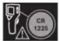
Button battery empty. Replace the button battery with a new one (see "Replacing the button battery", page 145).
Confirm the change by pressing the central multi-function button (17) with "OK".
Concept explanations
For more information, see
www.bosch-professional.com/thermal.
Infrared heat radiation
Infrared heat radiation is electromagnetic radiation emitted by every body with a temperature above 0 Kelvin (-273 °C). The amount of radiation varies depending on the temperature and the emissivity of the body.
Emissivity
The emissivity of an object depends on the material and the surface structure. It indicates how much infrared heat radiation the object emits compared to an ideal heat radiator (black body, emissivity € = 1) and is therefore a value between 0 and 1.
Thermal bridge
A thermal bridge is a point in the external wall of a building where, due to the construction, high heat loss occurs in a specific area.
Thermal bridges can lead to an increased risk of mold.
Reflected temperature / reflectivity of the object
Reflected temperature is the heat radiation that does not originate from the object itself. Depending on the surroundings and material, ambient radiation is reflected onto the object to be measured, thus adversely affecting the actual temperature result.
Object distance
The distance between the measurement object and the measuring tool affects the size of the area recorded per pixel. As the object distance increases, you can capture increasingly larger objects.
| Mesafe (m) Kızılötesi piksel boyutu (mm) | Genişlik × yükseklik kızılötesi alan (m) |
| 0,30 1,14 ~ 0,29 × 0,22 | |
| 0,55 2,08 ~ 0,53 × 0,40 | |
| 1,00 3,79 ~ 0,97 × 0,73 | |
| 2,00 7,58 ~ 1,94 × 1,46 | |
| 5,00 18,95 ~ 4,85 × 3,64 |
Maintenance and service
Maintenance and cleaning
Store and transport the measuring tool only in suitable packaging similar to its original packaging.
Always keep the measuring tool clean. A dirty infrared sensor (5) can adversely affect measurement accuracy.
No liquid must enter the measuring tool during cleaning.
Do not attempt to clean dirt on the infrared sensor (5), camera (3), work light (4), or laser output aperture (2) with sharp objects. Do not wipe the infrared sensor and camera (risk of scratching).
Clean the surface, especially near the output aperture, at regular intervals, and ensure that no lint is left behind.
If you want your measuring tool to be recalibrated, please contact an authorized Bosch customer service.
If the measuring tool needs to be repaired, send it in its original packaging.
There are no user-serviceable parts inside the measuring tool. Opening the housing may damage the measuring tool.
Replacing the button battery (see Figure C)
Open the cover (11).
Unscrew the relevant screw (10) from the button battery holder assembly.
Pull the button battery holder assembly (9) out of the measuring tool. Replace the button battery with a new one. After inserting the button battery holder assembly, tighten the screw (10) again.
Customer service and application consulting
Customer service answers your questions regarding the repair and maintenance of your product as well as spare parts. Exploded views and information on spare parts can also be found at: www.bosch-pt.com
The Bosch application consulting team will be happy to assist you with questions about our products and accessories.
In all correspondence and spare part orders, please always specify the 10-digit product code on the product's type plate.
Turkey
Marmara Elektrikli El Aletleri Servis Hizmetleri Sanayi ve Ticaret Ltd. Şti.
Tersane cd. Zencefil Sok.No:6 Karaköy
Beyoğlu / İstanbul
Tel.: +90 212 2974320
Fax: +90 212 2507200
E-mail: info@marmarabps.com
Bağrı açıklar Oto Elektrik
Motorlu Sanayi Çarşısı Doğruer Sk. No:9
Selçuklu / Konya
Tel.: +90 332 2354576
Tel.: +90 332 2331952
Fax: +90 332 2363492
E-mail: bagriaciklarotoelektrik@gmail.com
Akgül Motor Bobinaj San. Ve Tlc. Ltd. Şti
Alaaddinbey Mahallesi 637. Sokak No:48/C
Nilüfer / Bursa
Tel.: +90 224 443 54 24
146 | Turkish
Fax: +90 224 271 00 86
E-mail: info@akgulbobinaj.com
Ankaralı Elektrik
Eski Sanayi Bölgesi 3. Cad. No: 43
Kocasinan / KAYSERİ
Tel.: +90 352 3364216
Tel.: +90 352 3206241
Fax: +90 352 3206242
E-mail: gunay@ankarali.com.tr
Asal Bobinaj
Eski Sanayi Sitesi Barbaros Cad. No: 24/C
Canik / Samsun
Tel.: +90 362 2289090
Fax: +90 362 2289090
E-mail: bpsasalbobinaj@hotmail.com
Aygem Elektrik Makine Sanayi ve Tic. Ltd. Şti.
10021 Sok. No: 11 AOSB
Çiğli / İzmir
Tel.: +90 232 3768074
Fax: +90 232 3768075
E-mail: boschservis@aygem.com.tr
Bakırcıoğlu Elektrik Makine Hırdavat İnşaat Nakliyat Sanayi ve Ticaret Ltd. Şti.
Karaağaç Mah. Sümerbank Cad. No:18/4
Merkez / Erzincan
Tel.: +90 446 2230959
Fax: +90 446 2240132
E-mail: bilgi@korfezelektrik.com.tr
Bosch Sanayi ve Ticaret A.Ş.
Elektrikli El Aletleri
Aydınevler Mah. İnönü Cad. No: 20
Küçükyalı Ofis Park A Blok
34854 Maltepe-Istanbul
Tel.: 444 80 10
Fax: +90 216 432 00 82
E-mail: iletisim@bosch.com.tr
www.bosch.com.tr
Bulsan Elektrik
Istanbul Cad. Devrez Sok. Istanbul Carsi
No: 48/29 Iskitler
Ulus / Ankara
Tel.: +90 312 3415142
Tel.: +90 312 3410302
Fax: +90 312 3410203
E-mail: bulsanbobinaj@gmail.com
Cozum Bobinaj
Kusget San.Sit. A Blok 11 Nolu Cd. No:49/A
Sehitkamil/Gaziantep
Tel.: +90 342 2351507
Fax: +90 342 2351508
E-mail: cozumbobinaj2@hotmail.com
Onarim Bobinaj
Raif Pasa Caddesi Cay Mahallesi No:67
İskenderun / HATAY
Tel.: +90 326 613 75 46
E-mail: onarim_bobinaj31@mynet.com
Faz Makine Bobinaj
Cumhuriyet Mah. Sanayi Sitesi Motor
İşleri Bölümü 663 Sk. No:18
Murat Paşa / Antalya
Tel.: +90 242 3465876
Tel.: +90 242 3462885
Fax: +90 242 3341980
E-mail: info@fazmakina.com.tr
Günşah Otomotiv Elektrik Endüstriyel Yapı Malzemeleri San ve Tic. Ltd. Şti
Beylikdüzü Sanayi Sit. No: 210
Beylikdüzü / İstanbul
Tel.: +90 212 8720066
Fax: +90 212 8724111
E-mail: gunsahelektrik@ttmail.com
Sezmen Bobinaj Elektrikli El Aletleri İmalatı San ve Tic. Ltd. Şti.
Ege İş Merkezi 1201/4 Sok. No: 4/B
Yenişehir / İzmir
Tel.: +90 232 4571465
Tel.: +90 232 4584480
Fax: +90 232 4573719
E-mail: info@sezmenbobinaj.com.tr
Üstündağ Bobinaj ve Soğutma Sanayi
Nusretiye Mah. Boyacılar Aralığı No: 9
Çorlu / Tekirdağ
Tel.: +90 282 6512884
Fax: +90 282 6521966
E-mail: info@ustundagsogutma.com
IŞIKLAR ELEKTRİK BOBİNAJ
Karasoku Mahallesi 28028. Sokak No:20/A
Merkez / ADANA
Tel.: +90 322 359 97 10 - 352 13 79
Fax: +90 322 359 13 23
E-mail: isiklar@isiklarelektrik.com
You can find other services at:
www.bosch-pt.com/serviceaddresses
Transport
The lithium-ion (Li-Ion) batteries inside the tool are subject to the provisions of the dangerous goods transport regulations. The batteries can be transported by the user on the roads without any further obligation.
When sending via third parties (e.g. by air or freight company), special provisions regarding packaging and labeling must be observed. When preparing the shipment, assistance from a dangerous goods specialist should be obtained.
Only send batteries if their housings are undamaged. Cover open contacts and pack the battery so that it cannot move around in the packaging. Please also observe any additional national regulations.
Disposal

Measuring devices, batteries, accessories, and packaging materials should be sent to a recycling center for environmentally friendly disposal.
Do not dispose of measuring devices and batteries in household waste!
For EU countries only:
Disused and defective measuring tools or used batteries/rechargeable batteries must be disposed of separately. Use the designated collection systems.
Waste electrical and electronic equipment, if disposed of improperly, may have harmful effects on the environment and human health due to the presence of potentially hazardous substances.
Batteries/rechargeable batteries:
Lithium-ion:
Please follow the instructions in the "Transport" section (see "Transport", page 146) and confirm.
Polish
Safety Instructions

To work efficiently and safely with the measuring tool, read and follow all instructions. If the measuring tool is not used in accordance with these instructions, the operation of the built-in safety features may be impaired. Ensure that the warning labels on the measuring tool are legible. PLEASE KEEP AND CAREFULLY STORE THESE INSTRUCTIONS, AND WHEN GIVING OR SELLING THE MEASURING TOOL, PASS THEM ON TO THE NEW USER.
Caution: Use of controls or adjustments or performance of procedures other than those specified herein may result in hazardous radiation exposure. The measuring tool is supplied with a laser warning label (marked with a number on the diagram of the measuring tool on the graphics page). If the laser warning label is not in Polish, it is recommended to affix the Polish label supplied with the tool before first use.
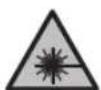
Do not direct the laser beam at persons or animals, and do not stare into the beam or its reflection.
This can cause someone to be blinded, accidents, or damage to eyesight.
If the laser beam is directed at the eye, close your eyes and move your head away from the beam's path. ▶ Do not make any changes or modifications to the laser device. ▶ Do not use laser working glasses (accessories) as protective goggles. Laser working glasses are used to make the laser beam easier to identify, but they do not protect against laser radiation. ▶ Do not use laser working glasses (accessories) as sunglasses or while driving. Laser working glasses do not provide complete protection against UV radiation and make it difficult to distinguish colors. ▶ Have the measuring device repaired only by qualified specialists and only with original spare parts. This ensures that the safety of the device is maintained. ▶ Do not allow children to use the laser measuring device without supervision. They may unintentionally blind others or themselves. ▶ Do not use this measuring device in explosive environments where flammable liquids, gases, or dusts are present. Sparks may be generated in the measuring device, which could ignite dust or fumes. ▶ Do not modify or open the battery. There is a risk of short circuit. If the battery is damaged or used improperly, fumes may be emitted. The battery may catch fire or explode. Ensure adequate ventilation and consult a doctor if you experience any symptoms. Fumes may irritate the respiratory tract. If the battery is handled improperly or damaged, flammable electrolyte may leak from the battery. Avoid contact with it, and if accidental contact occurs, rinse the affected area with water. If the liquid gets into the eyes, also seek medical advice. Electrolyte can cause skin irritation or burns. Sharp objects such as nails or screwdrivers, as well as external forces, can damage the battery. This may cause an internal short circuit, leading to overheating, explosion, or fire. Keep an unused battery away from paper clips, coins, keys, nails, screws, or other small metal objects that could bridge the contacts. A short circuit between battery contacts can cause burns or fire.
- Use the battery only in devices from the manufacturer. This is the only way to protect the battery from dangerous overload. Charge the battery only in chargers recommended by the manufacturer. Charging batteries other than those intended for a particular charger may create a fire hazard.

The battery must be protected from high temperatures, e.g., from direct sunlight, fire, dirt, water, and moisture. There is a risk of short circuit and explosion.
WARNING

Make sure that the coin cell is kept out of the reach of children. Coin cells are dangerous.
▶ Do not swallow coin cells or insert them into any other body opening. If you suspect that a coin cell has been swallowed or inserted into another body opening, seek medical advice immediately. Swallowing a coin cell can cause serious internal injuries and death within 2 hours.
Replace the coin cell properly. There is a risk of explosion.
Only use coin cells specified in these operating instructions. Do not use other coin cells or other power sources.
▶ Do not attempt to recharge the coin cell or short-circuit it. The coin cell may leak, explode, catch fire, and cause personal injury.
Dispose of discharged coin cells in accordance with regulations. Discharged coin cells may leak and damage the product or cause personal injury.
▶ Do not overheat the coin cell or throw it into a fire. The coin cell may leak, explode, catch fire, and cause personal injury.
▶ Do not damage or disassemble the coin cell. The coin cell may leak, explode, catch fire, and cause personal injury.
▶ A damaged coin cell must not come into contact with water. Lithium leaking from the cell can react with water to form hydrogen, which can lead to fire, explosion, or personal injury.
▶ Do not use the measuring tool if the coin cell compartment cannot be properly and completely closed. In such a case, remove the coin cell and have the measuring tool repaired.
▶ Large temperature differences in the thermal image can cause even high temperatures to be displayed in a color typically associated with low temperatures. Contact with such a surface can cause burns.
▶ Large temperature differences in the thermal image can cause even high temperatures to be displayed in a color typically associated with low temperatures. Contact with such a surface can cause burns.
Accurate temperature measurement is only possible when the set emissivity and the emissivity of the object are identical. The displayed temperature of objects may actually be higher or lower, which can pose a hazard if the object is touched.
Do not point the measuring tool directly at the sun or at high-power CO2 lasers. This can damage the detector.
Protect the measuring tool, especially the area around the camera and the infrared lens, from moisture, snow, dust, and dirt. Fogging or contamination of the receiver lens can falsify measurement results. Incorrect settings of the tool and other atmospheric factors can also lead to falsified measurements. The displayed temperature of objects may actually be higher or lower, which can pose a hazard if the object is touched.
Product description and intended use
Refer to the illustrations at the front of the operating instructions.
Intended use
The thermal imaging camera is intended for non-contact surface temperature measurements.
The displayed thermal image shows the temperature distribution in the field of view of the thermal imaging camera and thus enables the presentation of temperature deviations using a color scale.
When used properly, the tool enables non-contact detection of temperature differences or irregularities on the surfaces under investigation in order to identify possible anomalies, including:
- thermal insulation and other insulation (e.g., detection of thermal bridges), – operating central heating and hot water pipes (e.g., underfloor heating) in floors and walls, – overheated electrical components (e.g., fuses or terminals), – defective or damaged machine parts (e.g., overheating due to a defective ball bearing).
The tool is not suitable for measuring the temperature of gases.
The measuring tool must not be used for medical purposes.
For information on using the tool for veterinary purposes, please refer to:
www.bosch-professional.com/thermal.
The measuring tool is suitable for indoor and outdoor use.
The product is a consumer laser product in accordance with EN 50689.
The lighting of the measuring tool is intended to illuminate the immediate work area of the measuring tool when taking pictures; it is not lighting for continuous operation.
The laser points must not be used as a laser pointer. They are only used to mark the measuring surface.
Graphically depicted components
The numbering of the depicted components refers to the diagram of the measuring tool on the graphics page.
(1) Protective cap (2) Laser beam outlet opening (3) Vision camera (4) Work light (5) Infrared sensor (6) Pause/start measurement button
(7) Battery compartment
(8) Laser warning label
(9) Round battery holder
(10) Round battery holder screw
(11) Cover for USB port and round battery holder
(12) USB Type-C ®a) port
(13) Laser button
(14) Battery/battery adapter release button
(15) Rechargeable battery b)
(16) USB Type-C® cable b) (17) Multi-function button (18) On/off/back button (19) Display (20) Serial number (21) Battery adapter housing (22) Batteries b) (23) Battery adapter cover a) USB Type-C® and USB-C® are trademarks of USB Implementers Forum. b) The accessories shown or described are not included in the standard scope of delivery.
Indications
(a) Indication of emissivity (b) Indication of reflected temperature (c) Indication of average temperature (d) Symbol for full memory (e) Symbol for work light (f) Symbol for laser (g) Indication of charge status (h) Indication of maximum surface temperature in the measuring range (i) Scale (j) Indication of minimum surface temperature in the measuring range (k) Symbol for temperature scale lock (I) Indication of low temperature point (example) (m) Viewfinder with temperature indication (n) Indication of high temperature point (example) (o) Menu symbol
Technical data
| Kamera termowizyjna GTC 12V-450-13 | |
| Numer katalogowy | 3 601 K83 900 |
| Rozdzielczość czujnika podczerwieni 256 × 192 px | |
| Czułość termiczna A) | ≤50 mK |
| Zakres widmowy 8–14 μm | |
| Pole widzenia (FOV) A) | 55,6° × 42° |
| Rozdzielczość przestrzenn (IFOV) 3,79 mrad | |
| Odległość ustawiania ostrośc A) | ≥0,5 m |
| Ostrość stała | |
| Częstotliwość odświeżania obrazu termicznego ≤9 Hz | |
| Zakres pomiarowy, temperatura powierzchni A) | -20 ... +450°C |
| Dokładność pomiarowa, temperatura powierzchni A)(B)(C) | |
| >0°C ... ≤ +100°C D) | ±2°C |
| > +100°C E) | ±2% |
150 | English
Thermal camera GTC 12V-450-13
| Rozdzielczość temperatury 0,1°C | |
| Typ wyświetlacza TFT | |
| Przekątna wyświetlacza 2,8" | |
| Rozdzielczość wyświetlacza 480 × 360 px | |
| Rozdzielczość zintegrowanej kamery wizyjnej 2 MP (640 × 480 px) | |
| Format obrazu .jpg | |
| Zapisane elementy w cyklu zapisywania 1 × obraz termiczny (screenshot),1 × obraz rzeczywisty z wartościami temperatur (metadane) | |
| Maks. liczba obrazów w pamięci wewnętrznej 500 | |
| Maks. wysokość stosowania ponad wysokością referencyjną 2000 m | |
| Stopień zabrudzenia zgodnie z IEC 61010-1 2 | F) |
| Maks. wilgotność względna A) | 90% |
| Klasa lasera 2 | |
| Typ lasera <1 mW, 645–660 nm | |
| Rozbieżność wiązki laserowej 1,5 mrad (kąt pełny) | |
| Zasilanie | |
| - Akumulator (Li-ion) 12 V | |
| - Baterie (Al-Mn, z adapterem do baterii) | 4 × 1,5 V LR6 (AA) |
| - Akumulatorki (NiMH, z adapterem do baterii) | 4 × 1,2 V HR6 (AA) |
| Czas pracy G) | |
| - Akumulator (Li-ion) H,I) | 8 h |
| - Baterie (Al-Mn) | 4 h |
| Zasilanie zegara systemowego | CR1225 (bateria litowa 3 V) |
| Standard USB | 2.0 |
| Złącze USB | USB Type-C ® |
| Waga J) | 0,354 kg |
| Wymiary (długość × szerokość × wysokość) K) | 89 × 79 × 209 mm |
| Stopień ochrony (z wyjątkiem akumulatora/baterii, w pozycji pionowej) | IP54 |
| Zalecana temperatura otoczenia podczas ładowania | 0°C ... +35°C |
| Dopuszczalne temperatury otoczenia | |
| - Podczas pracy | -10°C ... +50°C |
| - Podczas przechowywania z akumulatorem | -20°C ... +50°C |
| - Podczas przechowywania bez akumulatora | -20°C ... +70°C |
| Zalecane akumulatory | GBA 12V... |
Thermal camera GTC 12V-450-13
Recommended chargers GAL 12...
GAX 18...
A) according to VDI 5585 (average value)
B) At ambient temperature 20–23°C and emissivity ≥0.95, measuring distance: 1 m, operating time: >5 min, aperture 150 mm, with work light and laser switched off
C) plus additional deviation depending on application (e.g., reflection, distance, ambient temperature)
D) Applies to the center point; for all other pixels, add ±1°C
E) Applies to the center point; for all other pixels, add ±1%
F) Only non-conductive contamination occurs, but from time to time, periodic current conduction due to condensation is to be expected.
G) With work light switched off and average display brightness setting
H) depending on the battery used
I) at an ambient temperature of 20-30°C
J) weight without battery/battery adapter/batteries
K) with GBA 12V 2.0Ah battery or battery adapter
The serial number (20) on the rating plate is used for unambiguous identification of the measuring tool.
Power supply for the measuring tool
The measuring tool can be powered by a Bosch lithium-ion battery, commercially available batteries, or commercially available NiMH rechargeable batteries.
Operation with battery (see figure A)
Only use the chargers listed in the technical data. Only these chargers are suitable for charging the lithium-ion battery used in the measuring tool.
Note: Due to international transport regulations, lithium-ion batteries are partially charged at the time of delivery. To ensure full battery performance, fully charge the battery before first use.
To insert the charged battery (15), slide it into the compartment (7) until it clicks into place.
To remove the battery (15), press the release buttons (14) and pull the battery out of the battery compartment (7). Do not use force.
Operation with batteries (see figure B)
It is recommended to operate the measuring tool with alkaline-manganese batteries or NiMH rechargeable batteries. Insert the batteries into the battery compartment.
The battery adapter is intended for use only with specified Bosch tools and must not be used with power tools.
To insert the batteries, slide the battery adapter housing (21) into the battery compartment (7). Place the batteries in the housing according to the diagram on the cover (23). Then slide the cover over the housing until it audibly clicks into place.
To remove the batteries (22), press the release buttons (14) on the cover (23), and then remove the cover. Take out the batteries. To remove the housing (21) located inside the battery compartment, insert your
fingers into it and pull it out of the measuring tool, pressing it slightly against the side wall.
Always replace batteries or rechargeable batteries as a complete set. Only use batteries or rechargeable batteries from the same manufacturer and with the same capacity.
If the measuring tool is not used for an extended period, remove the batteries or rechargeable batteries from it. Batteries and rechargeable batteries in a measuring tool that is not used for an extended period may corrode.
Instructions for proper handling of the rechargeable battery
Protect the rechargeable battery from moisture and water.
Store the rechargeable battery only at temperatures between -20 °C and 50 °C. Do not leave the rechargeable battery, e.g., in a car in summer.
A significantly shorter operating time after charging indicates that the rechargeable battery is worn out and must be replaced with a new one.
Follow the instructions for waste disposal.
Operation
Protect the measuring tool from moisture and direct sunlight.
Do not expose the measuring tool to extremely high or low temperatures, nor to temperature fluctuations. For example, do not leave it in a car for an extended period. In situations where the measuring tool has been subjected to greater temperature fluctuations, wait until it returns to normal temperature before using it. Extremely high or low temperatures, as well as strong temperature fluctuations, can have a negative impact on the precision of the measuring tool.
▶ Pay attention to proper acclimatization of the measuring tool. In case of strong temperature fluctuations,
Temperature acclimatization of the device may take up to 60 minutes. This can happen when the measuring tool has been left in a cold car for a long time and is then used to take a measurement in a warm building.
Avoid strong impacts and do not drop the measuring tool. If the measuring tool is subjected to a strong external impact or if irregularities are detected during operation, have the measuring tool checked at an authorized Bosch service center.
Operation
Initial operation
After switching on the measuring tool for the first time or after restoring the factory settings, several basic settings must be reconfigured. Select the desired values by pressing the multi-function button (17) on its lower, upper, left, or right side. Press the multi-function button (17) in the center to confirm the selection. After confirming the selection, the next setting appears on the display. The status bar at the top shows the total number of settings and the number of remaining settings.
The following basic settings are available:
Switching on/off
To take a measurement, open the protective cap (1). During operation, ensure that the infrared sensor is not closed or covered.
To switch on the measuring tool, press the on/off switch (18). The start sequence appears on the display (19). Once the start sequence has finished, the measuring tool begins measuring and continues to do so continuously until it is switched off.
Note: In the first few minutes, the measuring tool may need to adjust more frequently because the sensor temperature and the ambient temperature are not yet equalized. The sensor readjustment enables precise measurement.
During this time, the temperature reading may be preceded by the symbol \~. This effect is more pronounced with strong fluctuations in ambient temperature. Therefore, switch on the measuring tool a few minutes before the planned start of measurement so that it can acclimatize to the working conditions.
To switch off the measuring tool, press the on/off switch (18) for more than 1 second. The measuring tool switches off after saving all settings. Close the protective cap (1) to ensure safe transport of the measuring tool.
In the main menu, you can select whether and after what time the measuring tool should switch off automatically (see "Main menu", page 154).
If the battery or the measuring tool is outside the operating temperature range specified in the technical data, the measuring tool switches off automatically after a brief warning (see "Errors – causes and remedies", page 156). Wait until the measuring tool has returned to normal temperature and switch it on again.
Navigating the menus
Navigating the various menus of the measuring device:
– Displaying menu bars: Press the multifunction button (17) in the center or on the left. The menu bars appear on the right and left sides of the display, with the main menu highlighted. – Browsing the left menu bar/navigating the main menu: Press the multifunction button (17) at the top, bottom, left, or right. – Switching to the left or right menu bar: Press the multifunction button (17) on the left or right. – Confirming a selection/entering a submenu: Press the multifunction button (17) in the center. – Returning from a submenu to a higher-level menu: Press the back button (18).
Preparations for measurement
Setting the emissivity before measuring surface temperature
The emissivity of an object depends on the type of material and the structure of its surface. It indicates how much infrared radiation the object emits compared to an ideal physical body that emits heat (a perfect black body, emissivity \(\epsilon = 1\) ) and therefore represents a value from 0 to 1.
To determine the surface temperature, the natural infrared radiation emitted by the measured object is measured without contact. To obtain a correct measurement result, the emissivity set in the measuring device must be checked before each measurement and, if necessary, adjusted to the measured object.
The emissivity values preset in the measuring device serve as reference values.
The user can select one of the preset emissivity values or enter an exact numerical value. Set the desired emissivity in the menu → (see "Main menu", page 154).
Correct temperature measurement is only possible if the set emissivity and the emissivity of the object are identical.
The lower the emissivity, the greater the influence of the reflected temperature on the measurement result. Therefore, when changing the emissivity, the reflected temperature value must also be adjusted. Set the reflected temperature in the menu <Measurement
parameters> → (see "Main menu", page 154).
Apparent temperature differences shown on the measuring device may result from variations in temperature and/or variations in emissivity. In the case of large variations in emissivity, the indicated temperature differences may differ significantly from the actual temperatures.
If there are several objects in the measurement area made of different materials or with different surface structures, the indicated temperature values may correspond to reality only for objects that match the set emissivity. For all other objects (with different emissivity), the indicated color differences can be used as a suggestion of possible temperatures.
Tips on measurement conditions
Strongly reflective or shiny surfaces (e.g., glossy tiles or polished metal) can significantly distort or interfere with temperature measurement. If necessary, the measuring surface can be covered with a dark, matte adhesive tape that conducts heat well. Wait until the tape temperature adjusts to the temperature of the measured surface.
For reflective surfaces, pay attention to the appropriate measurement angle so that thermal radiation reflected from other objects does not distort the measurement result. For example, during perpendicular measurements from the front, the reflection of the user's own body heat can interfere with the measurement. In the case of a flat surface, the outline and body temperature of the user (reflected value) may be indicated, which do not correspond to the actual temperature of the measured surface (emitted value, or actual surface temperature value).
Due to the measurement principle, measurements through transparent materials (e.g., glass or transparent plastics) are not possible.
The more accurate and stable the measurement conditions, the more precise the measurement results will be. Not only strong temperature fluctuations in the environment matter, but also strong temperature fluctuations of the measured object can affect measurement accuracy.
Smoke, steam/high humidity, and polluted air can interfere with infrared temperature measurement.
Tips to increase measurement accuracy:
– Approach the measured object as closely as possible to avoid the influence of interfering factors between the user and the measured surface.
– Therefore, before taking measurements, ventilate the rooms, especially when the air is polluted or very humid. After ventilation, wait until the room reaches its normal temperature.
Marking the measurement spot
▶ Never point the laser beam at people or animals, and do not look into the beam (even from a distance).
The measuring tool is equipped with a laser that allows marking the measurement spot.
Press and hold the laser button (13). The laser symbol (f) will be displayed on the status bar, and a red circle (m) will appear around the crosshair. The laser and crosshair coincide exactly at a distance of 1 m. After releasing the laser button (13), the laser turns off.
Interpreting temperatures using the scale
On the right side of the display there is a scale (i). The values at the top and bottom of the scale correspond to the maximum temperature (h) or minimum temperature (j) recorded in the thermal image. The scale takes into account 99.99% of all pixels. The color assignment to a given temperature value in the image is done uniformly (linearly).
Using different shades, the temperatures between the two limit values can be arranged. A temperature that is equidistant from the maximum and minimum values can, for example, be assigned to the middle range of the color scale.
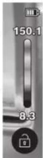
To determine the temperature of a specific area, move the measuring device so that the viewfinder with the temperature indication (m) is aimed at the desired point or area. In automatic mode, the color spectrum of the scale is always distributed linearly (= evenly) across the entire measured area between the maximum and minimum temperatures.
The measuring device shows all measured temperatures in the measurement zone in relation to each other. If, for example, in the color presentation, heat is indicated as a bluish hue on the color palette, this means that the bluish areas belong to the lower temperature values in the current measurement zone. However, these zones may correspond to a temperature range that, under certain conditions, could cause injury. Therefore, always pay attention to the temperatures indicated on the scale or the temperature indicated directly at the viewfinder.
Functions
Familiarize yourself with the information on navigating the various menus (see "Navigating the Menus", page 152).
Illumination of the measured object
The measuring device is equipped with a work light (4). It is intended for illuminating the immediate work area of the measuring device when taking pictures; it is not for continuous operation.
To switch the illumination on/off, open the sidebar on the left. Go to the menu item / and confirm the selection. When the work light is on, a corresponding indication appears on the status bar.
The illumination switches off automatically after 2 minutes to avoid affecting measurement accuracy.
The automatic switch-off time can be set in the menu under the item .
Overlaying the thermal image on the real image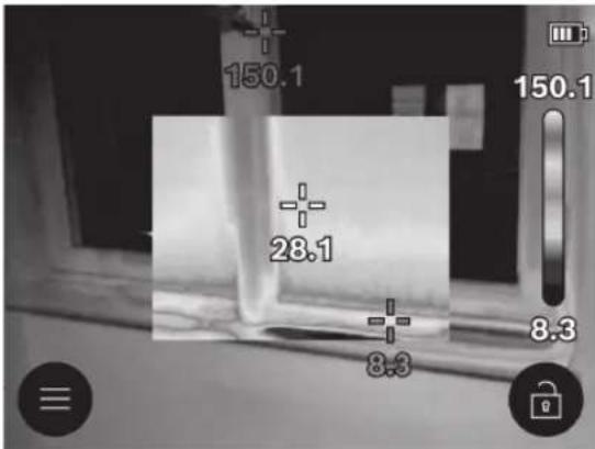
For better orientation (= positioning of the recorded thermal image in space), the real image can also be activated when temperatures are aligned.
Note: Accurate overlay of the real and thermal images is possible at a distance of 1 m. At other distances from the measured object, the real image and the thermal image may be offset relative to each other. This offset can be corrected using special Bosch software. Information on the software and its compatibility can be found on the product page of the measuring device or at: www.bosch-professional.com/thermal.
The measuring device offers the following options:
- 100% infrared image
Only the thermal image is displayed.
- Transparent image
The displayed thermal image is transparent and overlaid on the real image. This makes it easier to identify objects.
To activate/deactivate this setting, open the sidebar on the left and go to the menu item / . Confirm the selection by pressing the multifunction button (17) in the middle.
- Picture-in-picture
The displayed thermal image is cropped on the sides, and the surrounding area is shown as a real image. This setting makes it easier to locate the measured area in space.
To activate/deactivate this setting, open the sidebar on the left and go to the menu item / . Confirm the selection by pressing the multifunction button (17) in the middle.
Adjusting the color distribution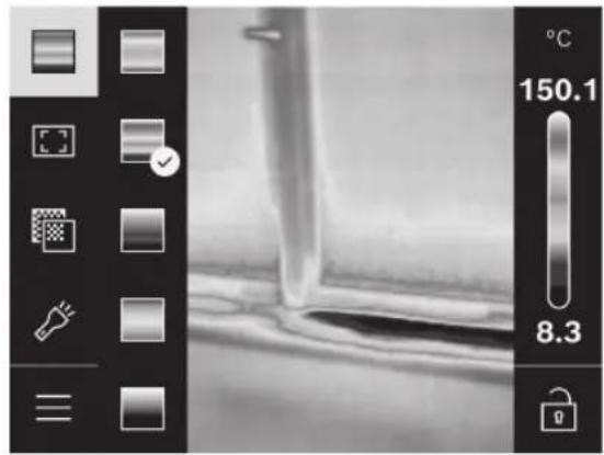
Depending on the measurement conditions, different color palettes can make it easier to analyze the thermal image and present objects or situations on the display more clearly. This has no effect on the measured temperatures. It only changes the presentation of temperature values.
To change the color palette, open the sidebar and go to the menu item "Color palette". Confirm the selection by pressing the multifunction button (17) in the middle.
Locking the scale
The distribution of colors on the thermal image is adjusted automatically, but it can be locked by pressing the multifunction button (17) to the right, then in the middle. This allows you to compare thermal images recorded under different temperature conditions (e.g., when checking several rooms for thermal bridges) or to hide a very cold or very hot object on the thermal image whose presence would disturb the thermal image (e.g., a radiator as a hot object when looking for thermal bridges).
To switch the scale back to automatic mode, open the sidebar on the right and press the multifunction button (17) in the middle. The temperatures will be dynamically adjusted to the measured minimum and maximum values.
Main menu
Open the sidebar on the left (see "Navigating through the menus", page 152). To go to the main menu, press the multifunction button (17) in the middle.
In this menu item, saved images can be deleted individually or all at once.
-
- (a)
For some of the most popular materials, the user can select a preconfigured emissivity. To facilitate searching, the values have been grouped in an emissivity catalog. In the menu item
first select the appropriate category, then the material. If the exact emissivity of the measured object is known to the user, they can also set it as a numerical value in the menu item .
• (b)
Setting this parameter improves the measurement result especially for materials with low emissivity (= strong reflection). In some situations (especially in enclosed rooms), the reflected temperature corresponds to the ambient temperature. If objects with strongly varying temperatures near highly reflective objects could influence the measurement, this value should be adjusted. To do this, press the multi-function button (17) on the left or right.
-
To ensure high accuracy over the entire measurement range, the measurement is performed in 2 temperature ranges. The measuring device operating in measurement function automatically selects the appropriate temperature range based on the temperature distribution in the thermal image. It analyzes how many measurement values are above a certain temperature threshold. If the measurement involves very small but hot objects, a low temperature range that is unsuitable for measuring high temperatures may be selected. This can be recognized by the symbol \~ preceding the temperature value. In such a case, switch to the measurement function <100 °C ... 450 °C> or <-20 °C ...
100 °C>, in which the color distribution corresponds to the set temperature range. The setting is visible on the scale as an arrow pointing up or down.
-
• (m): /
The point is displayed in the center of the thermal image and indicates the measured temperature value at that location in the image.
• (n): /
The point (= measurement pixel) with the highest temperature will be automatically indicated on the thermal image using a red reticle. This facilitates the detection of critical spots (e.g., a loose terminal in a distribution cabinet).
The point (= measurement pixel) with the lowest temperature will be indicated automatically on the thermal image by means of a blue reticle. This facilitates the detection of critical areas (e.g., leaks at a window).
- (i): /
- <Average temperature> (c): /
The average temperature (c) is displayed at the top left of the thermal image (it is the average temperature of all measured objects in the thermal image). It can help the user determine the reflected temperature.
-
-
In this menu item, you can adjust the brightness of the display backlight.
-
In this menu item, you can set the time after which the work light automatically turns off when no button is pressed.
-
In this menu item, you can set the time after which the measuring device automatically turns off if the user does not press any button during that time. The auto-off function can also be deactivated by selecting the setting .
-
In this submenu, in addition to setting the date and time, you can also change their display format.
-
In this menu item, you can select the language of the displayed readings.
-
In this menu item, you can restore the measuring device to factory settings and irreversibly delete all data. Depending on the circumstances, this may take a few minutes. Press the multifunction button (17) on the right to delete all files, or the multifunction button (17) on the left to cancel the deletion.
-
In this menu item, you can view information about the measuring device. This includes the serial number of the device and the version of the installed software. You can also find further information about the device and software updates here.
To exit any menu and return to the standard reading screen, you can also press the measurement button (6).
Software update for the measuring device
If necessary, you can update the software of the measuring device via the USB Type-C® connection. You will find more information at:
www.bosch-professional.com/thermal-update.
Documentation of measurement results
Saving measurement results
Immediately after switching on, the measuring device will start measuring and will continue to do so continuously until it is switched off.
To save an image, point the camera at the object being measured and press the measurement button (6). The image will be saved in the internal memory of the measuring device. The measurement will be paused and the image will be displayed on the screen. This allows you to take a closer look at the image and make adjustments later (e.g., color palette). If you do not want to save the paused image, you can return to measurement mode by pressing the measurement button (6) again. If you want to save the image in the internal memory of the measuring device, press the multifunction button (17) in the middle.
adjustments (e.g., color palette). If you do not want to save the paused image, you can return to measurement mode by pressing the measurement button (6) again. If you want to save the image in the internal memory of the measuring device, press the multifunction button (17) in the middle.
Viewing saved images
To view saved thermal images, proceed as follows:
- Immediately after saving, press the multifunction button (17) in the center again. The display will now show a preview of the last saved image.
- Alternatively, you can open the saved images in the menu item .
- To view the next saved thermal images, press the multifunction button (17) to the right or left.
Along with the thermal image, a real image is also saved. To display it, press the multifunction button (17) at the top or bottom.
After 5 seconds, the measuring device switches to full-screen format. In full-screen format, the displayed title bar disappears so that the user can examine all details in the thermal image.
By pressing the multifunction button (17) at the top and bottom, you can change the views.
Deleting saved images
To delete a single or all thermal images, press the multifunction button (17) in the center. A submenu will open.
- Here you can choose whether a specific image or all images should be deleted. Confirm the selection by pressing the multifunction button (17) in the center.
The user can select <Delete
all> and . Confirm the selection by pressing the multifunction button (17) in the center.
- In this submenu, you can also check information regarding emissivity and reflected temperature.
Parts of image files remain in memory and can be reconstructed. To delete images irreversibly, select in the main menu → .
Data transmission
Data transmission via USB connection
Open the cover (11) of the USB Type-C® port. Connect the USB Type-C® port (12) of the measuring tool to the computer using the USB Type-C® cable (16) included in the standard scope of delivery.
Switch on the measuring tool using the on/off switch (18).
Open the file explorer on the computer and select the drive GTC_450. The saved files can be copied from the internal memory of the measuring tool, moved to the computer, or deleted.
After completing the desired action, disconnect the drive from the computer in the standard way and switch off the measuring tool using the on/off switch (18).
Note: First use the command in the computer's operating system (e.g., eject the drive; remove the device), otherwise the internal memory of the measuring tool may be damaged.
Disconnect the USB Type-C® cable and close the cover (11). The USB connector cover must always be closed to prevent dust and moisture from entering.
Tip: The measuring tool should only be connected to the computer via USB. Attempts to connect to other devices may damage the measuring tool.
Tip: The USB Type-C® connector is only for data transmission. Do not use it to charge rechargeable batteries or batteries.
Processing thermal images
Saved thermal images can be processed using special Bosch software. Information about the software and its compatibility can be found on the product page of the measuring tool or at: www.bosch-professional.com/thermal.
Errors – causes and corrective action
In the event of a malfunction, the tool will restart and can be used again. Otherwise, the following overview of error messages may be helpful.
Error Cause Remedy
| Nie można włączyć urządzenia pomiarowego. | Akumulator/baterie są rozła- dowane | Należy naładować akumulator lub wymienić baterie. |
Battery error: Replace the battery or batteries.
Battery/batteries too hot or too cold
Wait until the battery returns to normal temperature or replace the battery or batteries.
Error Cause Solution
Measuring tool is too hot or too cold
Wait until the measuring tool returns to normal temperature.
Damaged USB port or damaged USB cable
Check whether the measuring tool can be connected to another computer. If not, send the measuring tool to an authorized Bosch service center.
Measuring tool cannot be connected to the compu-
Note: Always use the USB cable included in the scope of delivery.
ter.
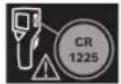
Flat coin cell battery: Replace the coin cell battery (see "Replacing the coin cell battery (see Fig. C)", page 158). Confirm the replacement ("OK") by pressing the multifunction button (17) in the center.
Terminology
You can find more information at: www.bosch-professional.com/thermal.
Infrared radiation
Infrared radiation is electromagnetic radiation emitted by any object with a temperature above 0 K (-273 °C). The amount of radiation emitted depends on the temperature and emissivity of the object.
Emissivity
The emissivity of an object depends on the type of material and the structure of its surface. It indicates how much infrared radiation the object emits compared to an ideal physical body that emits heat (a perfect black body, emissivity ε = 1) and therefore represents a value from 0 to 1.
Thermal bridge
A thermal bridge is a location in the external wall of a building where, due to construction reasons, increased heat loss occurs.
Thermal bridges can increase the risk of mold formation.
Reflected temperature / reflectivity of the object
Reflected temperature is thermal radiation whose source is not the object itself. Depending on the structure and material, radiation from the surroundings is reflected in the measured object and falsifies its actual temperature.
Object distance
The distance between the measured object and the measuring device affects the size of the surface area recorded by one pixel. As the distance increases, larger objects can be recorded.
| Odległość (m) Wielkość pikseli podczerwieni (mm) | Obszar podczerwieni szer. × wys. (m) |
| Odległość (m) Wielkość pikse-li podczerwieni (mm) | Obszar podczerwieni szer. × wys. (m) |
| 0,55 2,08 ~ 0,53 × 0,40 | |
| 1,00 3,79 ~ 0,97 × 0,73 | |
| 2,00 7,58 ~ 1,94 × 1,46 | |
| 5,00 18,95 ~ 4,85 × 3,64 |
Maintenance and service
Maintenance and cleaning
The measuring device should be stored and transported properly protected and in its original packaging.
The measuring device should be kept clean. A contaminated infrared sensor (5) can negatively affect measurement accuracy.
When cleaning the device, be careful that no liquid penetrates the interior of the measuring device.
Do not attempt to remove dirt from the infrared sensor (5), camera (3), work light (4), or the laser beam exit opening (2) with sharp objects. Do not wipe the infrared sensor or camera (risk of scratching the surface).
In particular, regularly clean the surfaces at the laser beam exit opening, carefully removing dust particles.
If the measuring device needs to be recalibrated, contact an authorized Bosch service center.
If repair is necessary, send the measuring device back in its original packaging.
There are no parts in the measuring device that require maintenance by the user. Opening the housing may damage the measuring device.
Replacing the round battery (see figure C)
Open the cover (11).
Unscrew the screw (10) of the round battery holder. Slide the round battery holder (9) out of the measuring device. Replace the round battery. After inserting the round battery holder, retighten the screw (10).
Customer service and usage advice
At the customer service point, you can get answers to questions about repairs and maintenance of the purchased product, as well as about spare parts. Technical drawings and information about spare parts can also be found at: www.bosch-pt.com
Bosch service office staff will be happy to assist with questions about our products and accessories.
For all inquiries and spare parts orders, it is necessary to provide the 10-digit catalog number found on the product's nameplate.
Robert Bosch Sp. z o.o.
Power Tools Service
Ul. Jutrzenki 102/104
02-230 Warsaw
At www.serwisbosch.com you will find all details regarding online service.
Tel.: 22 7154450
Fax: 22 7154440
E-Mail: bsc@pl.bosch.com
www.bosch-pt.pl
Further service addresses are listed below:
www.bosch-pt.com/serviceaddresses
Transport
The recommended lithium-ion batteries are subject to the requirements of dangerous goods regulations. The batteries can be transported by road by the user without any further conditions.
When shipping by third parties (e.g., air transport or via a forwarding company), special requirements regarding packaging and labeling must be observed. In such a case, an expert for dangerous goods must be consulted when preparing the goods for shipment.
Batteries may only be shipped if their housing is not damaged. Exposed contacts must be taped over, and the battery must be packed in such a way that it cannot move in the packaging. Any national regulations must also be taken into account.
Waste disposal

Measuring devices, rechargeable batteries/batteries, accessories, and packaging must be handed in for recycling in accordance with the applicable environmental protection regulations.
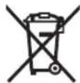
Do not dispose of measuring tools or rechargeable batteries/batteries with household waste!
For EU countries only:
Unusable measuring devices and damaged or exhausted rechargeable batteries/batteries must be disposed of separately. Use the designated collection systems.
In the event of improper disposal, used electrical and electronic equipment may have harmful effects on the environment and human health due to the potential presence of hazardous substances.
Rechargeable batteries/batteries:
Li-Ion:
Please follow the instructions in the Transport section (see "Transport", page 158).
Czech
Safety instructions

To ensure safe and reliable operation of the measuring instrument, it is necessary to read and follow all instructions. If the measuring instrument is not used in accordance with these instructions, the protective measures integrated in the measuring instrument may be impaired. Never allow the warning labels on the measuring instrument to become illegible. KEEP THESE INSTRUCTIONS IN A SAFE PLACE, AND IF YOU PASS THE MEASURING INSTRUMENT ON TO OTHERS, ENCLOSE THEM.
Caution – if equipment or adjustment devices other than those specified here are used, or if other procedures are carried out, this may result in exposure to hazardous radiation.
▶ The measuring instrument is supplied with a laser warning label (marked on the illustration of the measuring instrument on the page with figures).
▶ If the text on the warning label is not in your national language, cover it with the enclosed label in your language before first commissioning.

Do not point the laser beam at people or animals, and do not look directly into the laser beam or its reflection. This can cause dazzling, accidents, or damage to eyesight.
▶ If the laser beam hits the eye, deliberately close your eyes and immediately move your head away from the beam. ▶ Do not make any modifications to the laser device. Do not use the laser viewing glasses (accessory) as protective goggles. Laser viewing glasses are for better recognition of the laser beam; they do not protect against laser radiation. Do not use the laser viewing glasses (accessory) as sunglasses or in road traffic. Laser viewing glasses do not provide UV protection and impair color perception. Only have the measuring tool serviced by qualified specialists using original spare parts. This ensures that the safety of the measuring tool is maintained. Do not allow children to use the laser measuring tool without supervision. They could unintentionally dazzle other people or themselves. ▶ Do not operate the measuring tool in explosive atmospheres where flammable liquids, gases, or combustible dust are present. Sparks may be generated in the measuring tool, which could ignite dust or vapors. ▶ Do not modify or open the battery. There is a risk of short circuit. If the battery is damaged or used improperly, vapors may escape. The battery may catch fire or explode. Ensure fresh air supply and consult a doctor if you experience any issues. Vapors may irritate the respiratory tract. If the battery is used improperly or is damaged, flammable liquid may leak from it. Avoid contact with it. In case of accidental contact, rinse the area with water. If the liquid gets into the eyes, also seek medical attention. Leaking battery fluid can cause skin irritation or burns. ▶ Sharp objects such as nails or screwdrivers, or external force, can damage the battery. This can cause a short circuit inside, and the battery may catch fire, emit smoke, explode, or overheat. Store an unused battery away from paper clips, coins, keys, nails, screws, or other small metal objects that could bridge the contacts. A short circuit between battery contacts can result in burns or fire. - Use the battery only in products from the manufacturer. Only then is the battery protected against dangerous overload. - Charge the battery only with chargers recommended by the manufacturer. A charger that is
suitable for one type of battery may pose a fire risk if used with other batteries.


Protect the battery from heat, including prolonged direct sunlight, fire, dirt, water, and moisture. There is a risk of explosion and short circuit.


WARNING
Ensure that the button battery does not get into the hands of children. Button batteries are dangerous.
▶ Button cells must never be swallowed or inserted into any other body orifice. If you suspect that a button cell has been swallowed or has entered another body orifice, seek medical attention immediately. Swallowing a button cell can cause severe internal burns and death within 2 hours. ▶ When replacing the button cell, ensure correct replacement. There is a risk of explosion. Use only the button cells specified in these operating instructions. Do not use other button cells or other power sources. Do not attempt to charge the button cell and prevent short-circuiting of the button cell. The button cell may leak, explode, ignite, and cause injury. Remove discharged button cells and dispose of them properly. Discharged button cells may leak, which can cause damage to the product or injury to persons. ▶ Do not overheat the button cell or throw it into fire. The button cell may leak, explode, ignite, and cause injury. Do not damage or disassemble the button cell. The button cell may leak, explode, ignite, and cause injury. Ensure that a damaged button cell does not come into contact with water. Escaping lithium can react with water to produce hydrogen, which can cause fire, explosion, or injury. Do not use the measuring instrument if the button cell compartment cannot be closed properly and completely; remove the button cell and have the measuring instrument repaired. High temperature differences in the thermal image may mean that even high temperatures are displayed in a color associated with low temperatures. Contact with such a surface can cause burns. Correct temperature measurement is only possible when the set emissivity matches the object. Objects could be displayed with too high or too low temperatures, which can be dangerous when touched. Do not point the measuring instrument directly at the sun or at a high-power CO₂ laser. This could damage the detector.
▶ Protect the measuring instrument, especially the camera area and the infrared lens, from moisture, snow, dust, and dirt. The receiving lens could fog up or become dirty and distort the measurement results. Incorrect settings of the instrument and other atmospheric influencing factors can lead to incorrect measurements. Objects could be displayed with too high or too low temperatures, which can be dangerous when touched.
Product Description and Performance
Please observe the illustrations at the front of the operating instructions.
Intended Use
The measuring instrument is intended for non-contact measurement of surface temperatures.
The displayed thermal image shows the temperature distribution of the field of view of the thermal camera, thus allowing temperature deviations to be displayed in different colors.
When used correctly, temperature differences or anomalies of surfaces and objects can be examined to visualize components or weak points, including:
- thermal and other insulation (e.g., occurrence of thermal bridges),
- active heating and water lines (e.g., underfloor heating) in floors and walls,
- overheated electrical components (e.g., fuses or terminals),
- defective or damaged mechanical components (e.g., overheating due to defective ball bearings).
The measuring tool is not suitable for measuring the temperature of gases. The measuring tool must not be used for medical purposes. Information on veterinary use can be found at www.bosch-professional.com/thermal.
The measuring tool is suitable for use indoors and outdoors.
This product is a consumer laser product in accordance with EN 50689.
The light of this measuring tool is intended to illuminate the immediate work area of the measuring tool to create an image and does not serve as a permanent work light.
The laser point must not be used as a laser pointer. It serves exclusively to mark the measured area.
Displayed components
The numbering of the displayed components refers to the illustration of the measuring tool on the graphics page.
(1) Protective cap
(2) Laser beam outlet
(3) Visual camera
(4) Work light
(5) Infrared sensor
(6) Measurement button pause/start
(7) Battery compartment opening
(8) Laser warning label
(9) Coin cell battery holder
(10) Coin cell battery holder screw
(11) Cover for USB socket and coin cell battery holder
(12) USB Type-C® socket a)
(13) Laser button
(14) Battery/ battery adapter release button
(15) Battery b)
(16) USB Type-C® cable ®b)
(17) Multifunction button
(18) On/off button/back button
(19) Display
(20) Serial number
(21) Battery adapter housing
(22) Battery b)
(23) Battery adapter cover
a) USB Type-C® and USB-C® are protected trademarks of USB Implementers Forum.
b) The accessories shown or described are not included in the standard delivery.
Indicators
(a) Emissivity indicator
(b) Reflected temperature indicator
(c) Average temperature indicator
(d) Full memory symbol
(e) Work light symbol
(f) Laser symbol
(g) Charge status indicator
(h) Maximum surface temperature indicator in the measurement area
(i) Scale
(j) Minimum surface temperature indicator in the measurement area
(k) Temperature scale locking symbol
(I) Cold spot indicator (example)
(m) Crosshair with temperature indicator
(n) Hot spot indicator (example)
(o) Menu symbol
Technical data
Thermal camera GTC 12V-450-13
Article number
3 601 K83 900
English | 161
Thermal camera GTC 12V-450-13
| Rozlišení infračerveného senzoru 256 × 192 px | |
| Teplotní citlivostA) | ≤ 50 mK |
| Spektrální rozsah 8–14 μm | |
| Zorné pole (FOV)A) | 55,6° × 42° |
| Prostorové rozlišení (IFOV) 3,79 mrad | |
| Ohnisková vzdálenostA) | ≥ 0,5 m |
| Ohnisko pevné | |
| Obnovovací frekvence termosnímku ≤ 9 Hz | |
| Rozsah měření povrchové teplotyA) | -20 až +450 °C |
| Přesnost měření teploty povrchuA)B)C) | |
| >0 °C až ≤ +100 °CD) | ±2 °C |
| >+100 °CE) | ±2 % |
| Teplotní rozlišení 0,1 °C | |
| Typ displeje TFT | |
| Velikost displeje 2,8" | |
| Rozlišení displeje 480 × 360 px | |
| Rozlišení integrované vizuální kamery 2 MP (640 × 480 px) | |
| Formát obrázků .jpg | |
| Počet prvků uložených při jednom procesu 1× termosnímek (screenshot) | |
1 × visual real image including temperature values (metadata)
| Max. počet snímků v interní paměti 500 | |
| Max. nadmořská výška pro použití 2 000 m | |
| Stupeň znečištění podle IEC 61010-1 2 | F) |
| Relativní vlhkost vzduchu max. A) | 90 % |
| Třída laseru 2 | |
| Typ laseru < 1 mW, 645–660 nm | |
| Divergence laserového paprsku | 1,5 mrad (plný úhel) |
| Napájení | |
| - Akumulátor (lithium-iontový) | 12 V |
| - Baterie (alkalicko-manganové s adaptérem pro baterie) | 4× 1,5 V LR6 (AA) |
| - Akumulátory (NiMH s adaptérem pro baterie) | 4× 1,2 V HR6 (AA) |
| Doba provozu G) | |
| - Akumulátor (lithium-iontový) H(j) | 8 h |
| - Baterie (alkalicko-manganové) | 4 h |
| Napájení pro systémový čas | CR1225 (lithiová baterie 3 V) |
| USB standard | 2.0 |
| USB rozhraní | USB Type-C |
| Hmotnost J) | 0,354 kg |
| Rozměry (délka × šířka × výška) K) | 89 × 79 × 209 mm |
| Stupeň krytí (kromě akumulátoru/baterií, ve svislé poloze) | IP54 |
| Doporučená teplota prostředí při nabíjení | 0 °C až +35 °C |
| Dovolená teplota prostředí | |
| - Při provozu | -10 °C až +50 °C |
| - Při skladování s akumulátorem | -20 °C až +50 °C |
162 | English
Thermal camera GTC 12V-450-13 - When stored without battery -20 °C to +70 °C
| Doporučené akumulátory GBA 12V... | |
| Doporučené nabíječky GAL 12... | GAX 18... |
A) According to VDI 5585 (mean value)
B) At ambient temperature 20–23 °C and emissivity ≥ 0.95, measuring distance: 1 m, operating time: > 5 min, aperture 150 mm, with work light and laser switched off
C) Plus deviation depending on application (e.g., reflection, distance, ambient temperature)
D) Applies to the center, for all other pixels additionally ±1 °C
E) Applies to the center, for all other pixels additionally ±1 %
F) Only non-conductive contamination occurs, but occasional temporary conductivity due to condensation is expected.
G) With work light switched off and medium display brightness
H) Depending on the battery pack used
I) At ambient temperature 20–30°C
J) Weight without battery pack/battery adapter/batteries
K) With GBA 12V 2.0Ah or battery adapter
The serial number (20) on the type plate serves for unambiguous identification of the measuring tool.
Power supply for the measuring tool
The measuring tool can be operated with a Bosch lithium-ion battery pack, with standard batteries, or with standard NiMH rechargeable batteries.
Operation with battery pack (see figure A)
Use only the chargers specified in the technical data. Only these chargers are suitable for the lithium-ion battery that can be used with your measuring tool.
Note: Lithium-ion batteries are supplied partially charged according to international transport regulations. To ensure full battery performance, fully charge the battery before first use.
To insert the charged battery (15), push it into the battery slot (7) until it clicks into place.
To remove the battery (15), press the release buttons (14) and pull the battery out of the battery slot (7). Do not use force.
Operation with batteries (see figure B)
For operating the measuring tool, we recommend using alkaline-manganese batteries or NiMH rechargeable batteries. Batteries are inserted into the battery adapter.
The battery adapter is intended exclusively for use in designated Bosch measuring tools and must not be used with power tools.
To insert batteries, slide the housing (21) of the battery adapter into the battery slot (7). Insert the batteries into the housing according to the illustration on the cover (23). Attach the cover to the housing until it clicks into place.
To remove the batteries (22), press the release buttons (14) on the cover (23) and pull off the cover. Remove the batteries. To remove the inner housing (21) from the battery slot, reach into
the housing and pull it out of the measuring tool with a slight push on the side of the measuring tool.
Always replace all batteries or rechargeable batteries at the same time. Use only batteries or rechargeable batteries from one manufacturer and with the same capacity.
If the measuring tool is not used for a longer period, remove the batteries or rechargeable batteries from it. Batteries and rechargeable batteries may corrode during prolonged storage in the measuring tool.
Note for optimal handling of the battery
Protect the battery from moisture and water.
Store the battery only in a temperature range from -20 °C to 50 °C. Do not leave the battery in a car in summer, for example.
A significantly shorter runtime after charging indicates that the battery is worn out and must be replaced.
Follow the disposal instructions.
Operation
▶ Protect the measuring tool from moisture and direct sunlight. ▶ Do not expose the measuring tool to extreme temperatures or temperature fluctuations. For example, do not leave it in a car for extended periods. In case of significant temperature fluctuations, allow the measuring tool to acclimate before use. Extreme temperatures or temperature fluctuations may affect the accuracy of the tool. Ensure proper acclimatization of the measuring tool. In case of strong temperature fluctuations, the acclimatization period may take up to 60 minutes. This can happen, for example, when you have stored the measuring tool in a cold car and then take measurements in a heated building. Avoid strong impacts or dropping the measuring tool. After exposure to strong external influences and in case of
unusual behavior, you should have the measuring tool checked by an authorized Bosch service center.
Initial Operation
At first start-up
When the measuring tool is switched on for the first time or after resetting to factory settings, some basic settings must be made. Select the desired values by pressing the multi-function button (17) down, up, left, or right. To confirm the selection, press the multi-function button (17) in the middle. After confirming the selection, the next setting will be displayed on the screen. The status bar at the top shows the total number and the number of remaining settings.
The following basic settings are available:
-
-
-
-
- <Time>
Switching On and Off
When measuring, fold away the protective cap (1). While working, make sure that the infrared sensor is not closed or covered.
To switch on the measuring instrument, press the on/off button (18). The start sequence appears on the display (19). After the start sequence, the measuring instrument immediately begins measuring and continues to do so until it is switched off.
Note: In the first few minutes, the measuring instrument may calibrate more frequently because the sensor and ambient temperatures have not yet equalized. A new sensor calibration enables accurate measurement.
During this time, the temperature indicator may show the \~ symbol. This effect is intensified with strong fluctuations in ambient temperature. Therefore, you should switch on the measuring instrument several minutes before starting measurement, if possible, so that it can thermally stabilize.
To switch off the measuring instrument, keep the button (18) pressed for > 1 s. The measuring instrument saves all settings and then switches off. For safe transport of the measuring instrument, close the protective cap (1).
In the main menu, you can choose whether and after what period of time the measuring instrument should switch off automatically (see "Main menu", Page 165).
If the battery or the measuring instrument is outside the operating temperature specified in the technical data, the measuring instrument switches off automatically after a brief warning (see "Faults – causes and remedies", Page 167). Allow the measuring instrument to adjust to the temperature and then switch it on again.
Navigating the various menus
Navigating the various menus of the measuring instrument:
- Displaying the menu bars: Press the multifunction button (17) in the middle or on the left.
The menu bars appear on the display on the right and left, with the main menu highlighted.
- Scrolling in the left menu bar/main menu: Press the multifunction button (17) at the top, bottom, left, or right.
- Switching to the left or right menu bar: Press the multifunction button (17) on the left or right.
- Confirming a selection/entering a submenu: Press the multifunction button (17) in the middle.
- Returning from a submenu to a higher-level menu: Press the back button (18).
Preparing the measurement
Setting the emissivity for surface temperature measurement
The emissivity of an object depends on the material and structure of its surface. It indicates how much infrared thermal radiation the object emits compared to an ideal thermal radiator (black body, emissivity ε = 1), and therefore has a value from 0 to 1. To determine the surface temperature, the natural infrared thermal radiation emitted by the targeted object is measured contactlessly. For correct measurement, the set emissivity must be checked on the measuring instrument before each measurement and, if necessary, adjusted to the measured object. The emissivities preset in the measuring instrument are reference values.
You can select one of the preset emissivities or enter an exact numerical value. Set the desired emissivity in the menu → (see "Main menu", page 165).
Correct temperature measurement is only possible if the set emissivity matches the object.
The lower the emissivity, the greater the influence of reflected temperature on the measurement result. Therefore, whenever you change the emissivity, always adjust the reflected temperature. Set the reflected temperature in the menu → (see "Main menu", page 165).
Apparent temperature differences displayed by the measuring instrument may be related to different temperatures and/or different emissivities. With very different emissivities, the displayed temperature differences may differ significantly from the actual ones.
If there are several measured objects made of different materials or with different structures in the measurement area, the displayed temperature values are accurate only for objects that match the set emissivity. For all other objects (with different emissivities), the displayed color differences can be used as an indication of temperature relationships.
Notes on measurement conditions
Highly reflective or glossy surfaces (e.g., shiny tiles or bare metals) can strongly distort or influence the displayed results. If necessary, cover the measured area with a dark, matte adhesive tape that is a good thermal conductor. Allow the tape to briefly adjust to the surface temperature. For reflective surfaces, ensure a suitable measuring angle so that the reflected thermal radiation from other objects does not distort the result. For example, when measuring vertically from the front, reflections of your own radiated body heat can interfere. On a flat surface, the outlines and temperature of your body (reflected value) could be displayed, which do not correspond to
the actual temperature of the measured surface (emitted value, i.e., actual surface value).
Measurement through transparent materials (e.g., glass or transparent plastics) is not possible in principle.
The more accurate and reliable the measurement results, the better and more stable the measurement conditions. Significant fluctuations in ambient temperature are crucial, but strong fluctuations in the temperature of the measured object can also affect accuracy.
Smoke, steam, high humidity, or dusty air have a negative effect on infrared temperature measurement.
Instructions for better measurement accuracy:
- Get as close as possible to the object being measured to minimize interfering factors between you and the measured surface.
- Ventilate indoor areas before measuring, especially if the air is polluted or contains large amounts of steam. After ventilating, allow the space to reach its usual temperature again.
Marking the measuring point
▶ Do not point the laser beam at people or animals, and do not look into it yourself, even from a distance.
The measuring device is equipped with a laser for marking the measuring point.
Press and hold the laser button (13). The laser symbol (f) will appear on the status bar, and a red ring will appear around the crosshair (m). The laser and crosshair overlap precisely at a distance of 1 m. When you release the laser button (13), the laser turns off.
Assigning temperatures according to the scale
The scale (i) is displayed on the right side of the screen. The values at the top and bottom ends are based on the maximum (h) and minimum (j) temperatures recorded in the thermal image. The scale evaluates 99.99% of all pixels.
The assignment of color to temperature values in the image is evenly distributed (linear).
Using different color tones, temperatures can be assigned within these two boundary values. For example, a temperature exactly between the maximum and minimum values is assigned to the middle color range of the scale.
To determine the temperature of a specific area, move the measuring device so that the crosshair with the temperature indicator (m) points to the desired point or area.
In automatic settings, the color spectrum of the scale is always distributed linearly (= evenly) over the entire measurement range from maximum to minimum temperature.
The measuring device displays all measured temperatures in the measurement range in relation to each other. For example, if in the color display a warm area appears blue in the corresponding color scale, it means that bluish areas belong to the cooler measured values in the current measurement range. However, these areas may still be in a temperature range that could potentially cause injury. Therefore, always pay attention to the temperatures shown on the scale or directly on the crosshair.
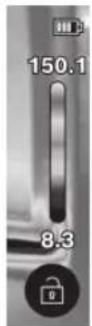
Functions
Follow the information for navigating the various menus (see "Navigating the various menus", Page 163)

Illuminating the measuring object
The measuring tool is equipped with a work light (4). It is intended for illuminating the immediate work area of the measuring tool for creating an image and is not intended as a permanent work light.
To switch the work light on/off, display the left side bar. Scroll to the menu item / and confirm the selection. When the work light is switched on, this is shown on the status bar.
The light automatically switches off after 2 minutes to avoid affecting the measurement accuracy.
You can set the automatic switch-off time in the menu in .
Overlaying the thermal image and the real image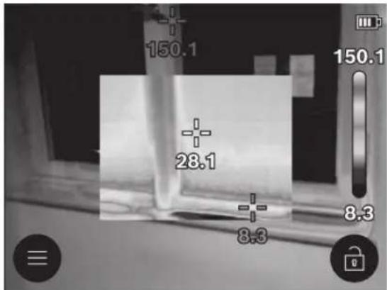
For better orientation (= spatial assignment of the displayed thermal image), a visual real image can be assigned to aligned temperature areas.
Note: The overlay of the real image and the thermal image is accurate at a distance of 1 m. At other distances to the measuring object, there is a shift between the real image and the thermal image. This shift can be compensated for using special Bosch applications. Information on the applications and their compatibility can be found on the product page of the measuring tool or at www.bosch-professional.com/thermal.
The measuring tool offers you the following options:
- 100% infrared image
Only the thermal image is displayed.

- Transparency
The displayed thermal image is transparently overlaid on the real image. This allows objects to be recognized better.
To activate/deactivate the setting, display the left side bar and scroll to the menu item <See.
Image overlay >/. Confirm the selection
by pressing the multifunction button (17) in the center.
- Picture-in-picture
The displayed thermal image is cropped and the surrounding area is shown as a real image. This setting improves the local assignment of the measured area.
To activate/deactivate the setting, display the left sidebar and scroll to the menu item / . Confirm the selection by pressing the multifunction button (17) in the center.
Color display settings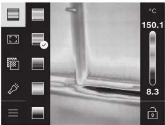
Depending on the situation of the respective measurement, different color scales can facilitate the analysis of the thermal image and objects or facts can be displayed more clearly on the screen. This has no effect on the measured temperatures. Only the display of thermal values changes.
To change the color scale, display the sidebar and scroll to the menu item "Color scale". Confirm the selection by pressing the multifunction button (17) in the center.
Fixing the scale
The color distribution in the thermal image is set automatically, but it can be fixed by pressing the multifunction button (17) to the right and then in the center. This allows comparing thermal images taken under different temperature conditions (e.g., when checking thermal bridges in different rooms) or hiding an extremely cold or hot object in the thermal image that would otherwise distort it (e.g., a heating element as a hot object when searching for thermal bridges).
To switch the scale back to automatic, display the right sidebar and press the multifunction button (17) in the center. The temperatures now behave dynamically again and adapt to the measured minimum and maximum values.
Main menu
Display the left sidebar (see "Navigating through different menus", Page 163). To go to the main menu, press the multifunction button (17) in the center.
- In this menu item you can delete saved images individually or all at once.
-
- (a)
For some frequently used materials, stored emissivities are available for selection. To facilitate searching, the values for groups are summarized in the emissivity catalog. First, select the correct category in the menu item, then the appropriate material. If you know the exact emissivity of the measured object, you can also set it as a numerical value in the menu item.
• (b)
Setting this parameter can improve the measurement result, especially for materials with low emissivity (= high reflectivity). In some situations (especially indoors), the reflected temperature corresponds to the ambient temperature. If objects with significantly different temperatures nearby could affect the measurement, you should adjust this value. To do this, press the multifunction button (17) left or right.
-
To ensure high accuracy over the entire measurement range, measurements are performed in two temperature ranges. In the measuring function, the device automatically selects the appropriate temperature range based on the temperature distribution in the thermal image. It evaluates how many measured values are above a certain temperature threshold. If very small but hot objects are to be measured, a low temperature range may be selected, which is unsuitable for high temperatures. This can be recognized by the preceding symbol – on the temperature indicator. In that case, switch to the measuring function <100 °C ... 450 °C> or <-20 °C ... 100 °C>, in which the color distribution corresponds to the set temperature range. The setting is marked on the scale with an arrow up or down.
-
- (m): / The point is displayed in the center of the thermal image and represents the measured temperature value at that location.
- (n): / The point with the highest temperature (= measuring pixel) is marked on the thermal image with a red crosshair. This facilitates the search for critical locations (e.g., a loose terminal in a switchgear).
- (I): / The point with the lowest temperature (= measuring pixel) is marked on the thermal image with a blue crosshair. This facilitates the search for critical locations (e.g., a leak in a window). • (i): /
- (c): /
The average temperature (c) is displayed on the thermal image at the top left (average temperature of all measured values in the thermal image). This can help you determine the reflected temperature.
-
166 | English
-
In this menu item, you can set the brightness of the display lighting.
•
In this menu item, you can select the time interval for the automatic shutdown of the work light if you do not press any button.
•
In this menu item, you can select the time interval after which the measuring instrument automatically turns off if you do not press any button. You can also deactivate the automatic shutdown by selecting the setting .
•
In this submenu, in addition to setting the time and date, you can also change their respective formats.
•
In this menu item, you can select the language used in the display.
•
In this menu item, you can reset the measuring instrument to the factory settings and permanently delete all data. Under certain circumstances, this may take several minutes. Press the multifunction button (17) on the right to delete all files, or the multifunction button (17) on the left to interrupt this process.
-
In this menu item, you can view information about the measuring instrument. Here you will find the serial number of the measuring instrument and the installed software version. In addition, you will find further information about the measuring instrument and the software update.
To exit any menu and return to the standard screen, you can also press the measurement button (6).
Software update of the measuring instrument
If necessary, you can update the measuring tool's software via the USB Type-C® interface. For more information, see:
www.bosch-professional.com/thermal-update.
Documentation of measurement results
Saving measurement results
Immediately after switching on, the measuring tool starts measuring and continues to do so continuously until it is switched off.
To save an image, aim the camera at the desired measuring object and press the measurement button (6). The image is saved in the internal memory of the measuring tool. The measurement freezes and is displayed on the screen. This allows you to carefully inspect the image and make additional adjustments (e.g., the color scale). If you do not want to save the frozen image, press the measurement button (6) again to resume measurement mode. To save the image in the internal memory of the measuring tool, press the multifunction button (17) in the middle.
Recalling saved images
To view saved thermal images, proceed as follows:
– Immediately after saving, press the multifunction button (17) in the middle again. The preview of the last saved image will now be displayed on the screen.
- Alternatively, you can view the saved images in the menu item .
– To navigate between saved thermal images, press the multifunction button (17) to the right or left.
In addition to the thermal image, a visual image was also saved. To view it, press the multifunction button (17) at the top or bottom.
After 5 seconds, the measuring tool switches to the full image preview. In the full image preview, the main bar display disappears so that you can see all the details of the thermal image.
By pressing the multifunction button (17) at the top and bottom, you can change the previews.
Deleting saved images
To delete individual or all thermal images, press the multifunction button (17) in the center. A submenu will open.
– Here you can choose whether to delete only this image or all images. Confirm the selection with the multifunction button (17) in the center. When selecting, you can choose between and . Confirm the selection with the multifunction button (17) in the center.
- In this submenu you can also view information about emissivity and reflected temperature.
Data fragments of the images will remain in memory and could be restored. For final deletion, select in the main menu
→ .
Data transfer
Data transfer via USB interface
Open the cover (11) of the USB Type-C® socket. Connect the USB Type-C® socket (12) of the measuring device to the computer using the supplied USB Type-C® cable (16).
Now turn on the measuring device with the power button (18).
On the computer, open the file browser and select the drive GTC_450. Saved files can be copied, moved to the computer, or deleted from the internal memory of the measuring device.
After completing the desired process, disconnect the drive from the computer in the standard way and turn off the measuring device again using the power button (18).
Caution: Always disconnect the drive from the operating system first (eject the drive), otherwise the internal memory of the measuring device may be damaged.
Disconnect the USB Type-C® cable and close the cover (11).
Always keep the USB interface cover closed to prevent dust or splashing water from entering.
Warning: Connect the measuring device via USB exclusively to a computer. Connecting to other devices may damage the measuring device.
Note: The USB Type-C® interface is intended exclusively for data transfer. Batteries and rechargeable batteries cannot be charged through it.
Processing thermal images
You can edit saved thermal images using special Bosch apps. Information about the apps and their compatibility can be found on the product page of the measuring tool or at www.bosch-professional.com/thermal.
Faults – causes and remedies
In the event of a malfunction, the measuring tool will restart and can then be used again. Otherwise, the following overview will help you with persistent error messages.
Error Cause Remedy The measuring tool cannot be switched on. Battery/rechargeable battery discharged Charge the rechargeable battery or replace the batteries.
 | Chyba akumulátoru/baterií Vyměňte akumulátor, resp. baterie. | |
 | Akumulátor/baterie příliš teplé, resp. příliš studené | Nechte akumulátor vytemperovat nebo akumulátor, resp. baterie vyměňte. |
 | Měřicí přístroj je příliš teplý nebo příliš studený | Nechte měřicí přístroj vytemperovat. |
 | Vadná USB přípojka nebo vadný USB kabel | Zkontrolujte, zda lze měřicí přístroj spojit s jiným počítačem. Pokud ne, pošlete měřicí přístroj do autorizovaného zákaznického servisu Bosch. |
| Měřicí přístroj nelze spojit s počítačem. | Upozornění: Používejte vždy USB kabel, který je součástí dodávky. | |
 | Knoflíková baterie vybitá Vyměňte knoflíkovou baterii (viz „Výměna knoflíkové baterie (viz obrázek C)“, Stránka 168). Potvrd’te změnu pomocí „OK“ stisknutím multifunkčního tlačítka (17) uprostřed. | |
The measuring tool cannot be connected to the computer.
Explanation of terms
Further information can be found at www.bosch-professional.com/thermal.
Infrared thermal radiation
Infrared thermal radiation is electromagnetic radiation emitted by every body with a temperature above 0 kelvin (-273 °C). The amount of radiation depends on the temperature and emissivity of the body.
Emissivity
The emissivity of an object depends on the material and structure of its surface. It indicates how much infrared thermal radiation an object emits compared to an ideal thermal radiator (black body, emissivity ε = 1), and therefore has a value from 0 to 1.
Thermal bridge
A thermal bridge is a location on the exterior wall of a building where locally increased heat loss occurs through the structure.
Thermal bridges can cause an increased risk of mold formation.
Reflected temperature/emissivity of the object
Reflected temperature is thermal radiation that does not originate from the object itself. Depending on the structure and material, radiation from the surrounding environment is reflected in the measured object, thus distorting the actual resulting temperature.
Object distance
The distance between the measured object and the measuring device affects the recorded area size per pixel. As the distance to the object increases, you can capture increasingly larger objects.
| Vzdálenost (m) Velikost infračerveného pixelu (mm) | Šířka × výška infračervené oblasti (m) |
| 0,30 1,14 ~ 0,29 × 0,22 | |
| 0,55 2,08 ~ 0,53 × 0,40 | |
| 1,00 3,79 ~ 0,97 × 0,73 | |
| 2,00 7,58 ~ 1,94 × 1,46 | |
| 5,00 18,95 ~ 4,85 × 3,64 |
Maintenance and service
Maintenance and cleaning
Store and transport the measuring device only in suitable packaging, such as the original packaging.
Always keep the measuring device clean. A dirty infrared sensor (5) can impair measurement accuracy.
No liquid must enter the measuring device during cleaning.
Do not attempt to remove dirt from the infrared sensor (5), camera (3), work light (4), or laser output opening (2) with pointed objects. Do not wipe the infrared sensor and camera (risk of scratching).
Regularly clean especially the surfaces at the laser output opening and watch out for fibers.
If you wish to have the measuring device recalibrated, contact an authorized Bosch customer service center.
For repairs, send the measuring device in its original packaging.
There are no parts inside the measuring device that require user maintenance. Opening the housing can destroy the measuring device.
Replacing the button battery (see figure C)
Open the cover (11).
Unscrew the screw (10) of the button battery holder. Pull the button battery holder (9) out of the measuring tool. Replace the button battery. After inserting the button battery, retighten the screw (10).
Customer service and usage advice
Customer service will answer your questions regarding repair and maintenance of your product as well as spare parts. Exploded views and information on spare parts can also be found at:
www.bosch-pt.com
The Bosch advisory team will be happy to help you with questions about our products and their accessories.
For all inquiries and spare parts orders, please always quote the 10-digit order number from the product nameplate.
Czech Republic
Robert Bosch odbytová s.r.o.
Bosch Service Center PT
K Vápence 1621/16
692 01 Mikulov
On www.bosch-pt.cz you can order repair of your machine or spare parts online.
Tel.: +420 519 305700
Fax: +420 519 305705
E-Mail: servis.naradi@cz.bosch.com
www.bosch-pt.cz
Further service addresses can be found at:
www.bosch-pt.com/serviceaddresses
Transport
The recommended lithium-ion batteries are subject to the requirements of the Dangerous Goods Act. These batteries can be transported by the user on the road without further conditions.
When sending via a third party (e.g., air transport or forwarding agency), special requirements for packaging and labeling must be observed. An expert on dangerous goods must be consulted when preparing the shipment.
Only send batteries if the housing is undamaged. Cover open contacts with adhesive tape and pack the battery so that it cannot move around in the packaging. Please also observe any additional national regulations.
Disposal

Measuring instruments, batteries, accessories, and packaging should be handed in for environmentally friendly recycling.
Do not dispose of measuring instruments and batteries in household waste!
Only for EU countries:
Unusable measuring instruments and defective or discharged batteries must be disposed of in separate waste collection. Use the designated collection points.
In the event of improper disposal, old electrical and electronic equipment may have harmful effects on the environment and human health due to the possible presence of hazardous substances.
Batteries:
Li-Ion:
Follow the instructions in the Transport section (see "Transport", page 168).
Slovak
Safety Instructions

To ensure safe and reliable operation of the measuring tool, read and follow all instructions. If the measuring tool is not used in accordance with these instructions, the integrated protective measures in the measuring tool may be adversely affected. Never allow the warning labels on the measuring tool to become illegible. KEEP THESE INSTRUCTIONS IN A SAFE PLACE AND ENCLOSE THEM WITH THE MEASURING TOOL WHEN GIVING IT TO A THIRD PARTY.
Caution – The use of other operating or adjusting devices or the use of other procedures than those specified here may result in hazardous exposure to radiation. ▶ The measuring tool is supplied with a laser warning label (marked on the illustration of the measuring tool on the page with figures).
- If the text of the laser warning label is not in the language of the country where the tool is used, affix the supplied label in your country's language over it before the first use.
- Do not direct the laser beam at persons or animals, and do not look into the direct or reflected laser beam yourself. This can blind persons, cause accidents, or damage eyesight.

▶ If the laser beam strikes the eye, consciously close your eyes and immediately turn your head away from the beam.
▶ Do not make any modifications to the laser device.
Do not use the laser viewing glasses (accessory) as protective goggles. The laser viewing glasses are used to better recognize the laser beam; however, they do not protect against laser radiation.
Do not use the laser viewing glasses (accessory) as sunglasses or in road traffic. The laser viewing glasses do not provide full UV protection and impair color perception.
Have the measuring tool serviced only by qualified specialist personnel using original replacement parts. This ensures that the safety of the measuring tool is maintained.
Have the measuring instrument repaired only by qualified specialist personnel using original spare parts. This ensures that the safety of the measuring instrument is maintained.
Do not allow children to use the laser measuring device without supervision. They could unintentionally cause blindness to others or themselves.
Do not operate the measuring device in environments with explosion hazards, where flammable liquids, gases, or dust are present. Sparks may be generated in this measuring device, which could ignite such dust or vapors.
- Do not modify or open the battery. There is a risk of short circuit.
▶ If the battery is damaged or used improperly, harmful vapors may be emitted from the battery. The battery may burn or explode. Ensure fresh air supply and seek medical attention if you experience discomfort. These vapors may irritate the respiratory tract.
▶ If the battery is used improperly or is damaged, liquid may leak from it. Avoid contact with this liquid. In case of accidental contact, rinse the area with water. If battery liquid comes into contact with the eyes, rinse the eyes and seek medical attention. Leaking battery liquid may cause skin irritation or burns.
Sharp objects such as nails or screwdrivers, or external force, can damage the battery. This may cause a short circuit inside, and the battery may catch fire, emit smoke, explode, or overheat.
Do not store an unused battery in a way that it could come into contact with paper clips, coins, keys, nails, screws, or other small metal objects that could bridge the contacts. A short circuit between battery contacts may result in burns or fire.
- Use the battery only in products from the manufacturer. Only then will the battery be protected against dangerous overload.
Charge batteries only with chargers recommended by the manufacturer. If a charger intended for one type of battery is used to charge other batteries, there is a risk of fire.


Protect the battery from heat, including prolonged sunlight, fire, dirt, water, and moisture. There is a risk of explosion and short circuit.
WARNING

Ensure that button cells are kept out of the reach of children. Button cells are dangerous.
Button cells must not be swallowed or inserted into other body orifices. If you suspect that a button cell has been swallowed or inserted into another body orifice, seek medical attention immediately. Swallowing a button cell can cause severe internal burns and death within 2 hours.
▶ When replacing the button cell, ensure that the replacement is done correctly. There is a risk of explosion.
Use only the button cells specified in this operating manual. Do not use any other button cells or other electrical power sources.
Do not attempt to charge coin cell batteries and do not short-circuit them. The coin cell battery may leak, explode, ignite, and cause injury.
Dispose of discharged coin cell batteries in accordance with regulations. Discharged coin cell batteries may leak and damage the product or cause injury.
Do not overheat the coin cell battery or throw it into fire. The coin cell battery may leak, explode, ignite, and cause injury.
Do not damage or disassemble the coin cell battery. The coin cell battery may leak, explode, ignite, and cause injury.
Prevent contact of a damaged coin cell battery with water. Leaking lithium may react with water and release
hydrogen, which can cause fire, explosion, or injury.
If the coin cell battery holder cannot be properly and completely closed, do not use the measuring instrument, remove the coin cell battery, and have the measuring instrument repaired. ▶ Large temperature differences in the thermal image can cause even high temperatures to be displayed in a color that is assigned to low temperatures. Contact with such a surface can cause burns. Accurate temperature measurement is only possible when the set emissivity matches the emissivity of the object. Objects may be displayed with too high or too low temperature, which can lead to danger upon contact. ▶ Do not point the measuring instrument directly at the sun or at a high-power CO₂ laser. This can damage the detector. ▶ Protect the measuring instrument, especially the camera area and infrared lens, from moisture, snow, dust, and dirt. The receiving lens could fog up or become dirty and distort measurement results.
Incorrect device settings and other atmospheric influences can lead to incorrect measurements. Objects may be displayed with too high or too low temperature, which can lead to danger upon contact.
Product Description and Performance
Please also refer to the illustrations at the front of the operating instructions.
Intended Use
This thermal camera is intended for non-contact measurement of surface temperatures.
The displayed thermal image shows the temperature distribution in the field of view of the thermal camera and thus allows temperature deviations to be displayed in various colors.
In this way, with professional use, temperature differences or conspicuous fluctuations of surfaces and objects can be examined without contact, in order to make structural parts and/or possible weak points visible, etc.
- Insulation and isolation (e.g., locating thermal bridges),
- Active heating and hot water pipes (e.g., underfloor heating) in floors and walls, – overheated electrical components (e.g., fuses or terminals), – faulty or damaged machine parts (e.g., overheating due to a defective ball bearing).
The measuring tool is not intended for measuring gas temperature.
The measuring tool must not be used for medical purposes. For information regarding veterinary use, please visit www.bosch-professional.com/thermal.
This measuring tool is suitable for indoor and outdoor use.
This product is a consumer laser product in accordance with EN 50689.
The light of this measuring tool is intended to illuminate the immediate work area of the measuring tool when capturing images and does not serve as a permanent work light.
The laser point must not be used as a laser pointer. It serves exclusively to mark the measuring area.
Displayed components
The numbering of the individual components refers to the illustration of the measuring tool on the graphic page of this instruction manual.
(1) Protective cover (2) Laser beam outlet (3) Visual camera (4) Work light (5) Infrared sensor (6) Measurement pause/start button (7) Battery compartment (8) Laser warning label (9) Coin cell holder
(10) Coin cell holder screw
(11) Cover for USB socket and coin cell holder
(12) USB Type-C® socket a)
(13) Laser button
(14) Battery pack/charger release button
(15) Battery pack b)
(16) USB Type-C cable ®b)
(17) Multifunction button
(18) Power on/off button/Back button
(19) Display
(20) Serial number
(21) Battery pack housing
(22) Batteries b)
(23) Battery pack cover
a) USB Type-C® and USB-C® are trademarks of USB Implementers Forum. b) Accessories shown or described are not included in the standard scope of delivery.
Indicators
(a) Emission level indicator (b) Reflected temperature indicator (c) Average temperature indicator (d) Memory full symbol (e) Work light symbol (f) Laser symbol (g) Charge status indicator (h) Maximum surface temperature indicator in measuring range (i) Scale
(j) Minimum surface temperature indicator in measuring range (k) Set fixed temperature scale symbol (I) Cold spot indicator (example)
(m) Crosshair with temperature indication (n) Hot spot indicator (example) (o) Menu symbol
Technical data
| Termálna kamera GTC 12V-450-13 | |
| Číslo položky | 3 601 K83 900 |
| Rozlíšenie infračerveného senzora 256 × 192 px | |
| Teplotná citlivost A) | ≤ 50 mK |
| Spektrálny rozsah 8–14 μm | |
| Zorné pole (FOV) A) | 55,6° × 42° |
| Priestorové rozlíšenie (IFOV) 3,79 mrad | |
| Ohnisková vzdialenost A) | ≥ 0,5 m |
| Ohnisko Pevné | |
| Snímková frekvencia tepelného obrázka ≤ 9 Hz | |
| Rozsah merania povrchovej teploty A) | -20 ... +450 °C |
| Presnost' merania povrchovej teploty A)(B)(C) | |
| >0 °C ... ≤ +100 °CD) | ±2 °C |
| >+100 °CE) | ±2 % |
| Teplotné rozlíšenie 0,1 °C | |
| Typ displeja TFT | |
| Vel'kosť displeja 2,8" | |
| Rozlíšenie displeja 480 × 360 px | |
| Rozlíšenie zabudovanej vizuálnej kamery 2 MP (640 × 480 px) | |
| Formát obrázkov .jpg | |
| Počet prvkov uložených pri jednom uložení 1 × tepelný obrázok (snímka obrazovky) | |
| 1 × vizuálna reálna snímka vrátane teplotných hodnôt (metaú-daje) | |
| Max. počet obrázkov v internej pamäti obrázkov 500 | |
| Max. výška použitia nad referenčnou výškou 2 000 m | |
| Stupeň znečistenia podľa IEC 61010-1 2 | F) |
| Max. relatívna vlhkosť vzduchu A) | 90 % |
| Trieda lasera | 2 |
| Typ lasera | < 1 mW, 645–660 nm |
| Divergencia laserového lúča | 1,5 mrad (plný uhol) |
| Zdroj energie | |
| - Akumulátor (lítiovo-iónový) | 12 V |
| - Batérie (alkalicko-mangánové s adaptérom batérie) | 4 × 1,5 V LR6 (AA) |
| - Akumulátory (NiMH s adaptérom batérie) | 4 × 1,2 V HR6 (AA) |
| Doba prevádzky G) | |
| - Akumulátor (lítiovo-iónový) H)(I) | 8 h |
| - Batérie (alkalicko-mangánové) | 4 h |
| Elektrické napájanie systémového času | CR1225 (3 V lítiová batéria) |
| Štandard USB | 2.0 |
| USB rozhranie | USB Type-C® |
172 | Slovak
Thermal camera GTC 12V-450-13
| Hmotnost1) | 0,354 kg |
| Rozmery (dlžka × šírka × výška)K) | 89 × 79 × 209 mm |
| Stupeň ochrany (okrem akumulátora/batérií, vo vzpriamenej polohe) | IP54 |
| Odporúčaná teplota okolia pri nabíjaní 0 °C ... +35 °C | |
| Povolené teploty okolia | |
| - pri prevádzke -10 °C ... +50 °C | |
| - pri skladovaní s akumulátorom -20 °C ... +50 °C | |
| - pri skladovaní bez akumulátora -20 °C ... +70 °C | |
| Odporúčané akumulátory GBA 12V... | |
| Odporúčané nabíjačky GAL 12... | GAX 18... |
A) According to VDI 5585 standard (average value) B) At ambient temperature 20–23 °C and emissivity ≥ 0.95, measuring distance 1 m, operating time > 5 min, with aperture 150 mm, with work light and laser switched off C) Including application-dependent deviation (e.g., reflection, distance, ambient temperature) D) Applies to the center point, for all other pixels additionally ±1 °C E) Applies to the center point, for all other pixels additionally ±1 % F) Only non-conductive contamination occurs, but occasional temporary conductivity due to condensation is expected. G) With work light switched off and medium display brightness H) Depending on the battery used I) At ambient temperature 20-30°C J) Weight without battery/battery adapter/batteries K) With GBA 12V 2.0Ah or battery adapter The serial number (20) on the type plate serves for unambiguous identification of your measuring instrument.
Power supply for the measuring instrument
The measuring instrument can be operated with a Bosch lithium-ion battery, with commercially available batteries, or with commercially available NiMH rechargeable batteries.
Operation with battery (see figure A)
Use only the chargers listed in the technical data. Only these chargers are matched to the lithium-ion battery used in your measuring instrument.
Note: Lithium-ion batteries are supplied partially charged due to international transport regulations. To ensure full battery performance, fully charge the battery before first use.
When inserting the charged battery (15), push it into the battery compartment (7) until it audibly clicks into place.
To remove the battery (15), press the release buttons (14) and pull the battery out of the battery compartment (7). Do not use excessive force.
Operation with batteries (see figure B)
For operation of this measuring instrument, we recommend using alkaline-manganese batteries or NiMH rechargeable batteries.
Insert the batteries into the battery adapter.
The battery adapter is intended exclusively for use in Bosch measuring instruments that are designed for it and must not be used with power tools.
Before inserting the batteries, slide the battery adapter sleeve (21) into the battery compartment (7). Insert the batteries into the sleeve as shown on the closing cover (23). Attach the closing cover to the sleeve so that it clicks into place.
To remove the batteries (22), press the release buttons (14) of the closing cover (23) and pull off the closing cover. Remove the batteries. To remove the sleeve (21) from the battery compartment, reach into the sleeve and pull it out of the measuring tool with a slight push against the side wall.
Always replace all batteries or all rechargeable battery cells at the same time. When replacing, only use batteries from one manufacturer and always those with the same capacity.
If the measuring tool is not used for a longer period, remove the batteries or rechargeable batteries from it. Batteries and rechargeable batteries can corrode if stored in the measuring tool for a longer time.
Instructions for optimal handling of the rechargeable battery
Protect the rechargeable battery against moisture and water.
Store the rechargeable battery only at temperatures between -20°C and 50°C. Do not leave the rechargeable battery in a car, for example, in summer.
A significantly shortened operating time of the rechargeable battery after charging indicates that the battery is worn out and must be replaced with a new one.
Follow the notices regarding disposal.
Operation
▶ Protect the measuring tool against moisture and direct sunlight. Do not expose the measuring tool to extreme temperatures or temperature fluctuations. Do not leave it in a car for a longer period, for example. In case of larger temperature fluctuations, allow the measuring tool to warm up before putting it into operation. Extreme temperatures or temperature fluctuations can negatively affect the accuracy of the measuring tool. Ensure that the measuring tool acclimatizes properly. In case of large temperature fluctuations, acclimatization can take up to 60 minutes. This can be the case, for example, when you store the measuring tool in a cold vehicle and then take measurements in a warm building. Avoid strong impacts or dropping the measuring tool. After strong external influences and in case of noticeable changes in functionality, have the measuring tool checked by a Bosch service center.
Initial operation
At first start-up
At first start-up of the measuring tool or after resetting to factory settings, some basic settings must be made. Select the desired values by pressing the multi-function button (17) down, up, left, or right. Press the multi-function button (17) in the center to confirm your selection. After confirming the selection, the next setting appears on the display. The status bar at the top shows the total number and the number of remaining settings.
The following basic settings are available:
- <Time>
Switching on/off
When measuring, fold open the protective cap (1). During work, make sure that the infrared sensor is not closed or covered.
Switch on the measuring tool by pressing the on/off button (18). The start sequence appears on the display (19). After the start sequence, the measuring tool immediately begins measuring and continues to do so continuously until it is switched off.
Note: In the first few minutes, the measuring tool may calibrate itself more frequently, as the sensor temperature and the ambient temperature have not yet equalized. New sensor calibration enables precise measurement.
During this time, the temperature indication may be marked with the symbol \~. This effect is intensified with large fluctuations in ambient temperature. Therefore, switch on the measuring tool, if possible, a few minutes before starting the measurement so that it can thermally stabilize.
Switch off the measuring tool by pressing the on/off button (18) for > 1 s. The measuring tool saves all settings and then switches off. For safe transport of the measuring tool, close the protective cap (1).
In the main menu, you can select whether and after what time the measuring tool switches off automatically (see "Main menu", Page 175).
If the battery or the measuring tool is outside the operating temperature specified in the technical data, the measuring tool switches off automatically after a brief warning (see "Errors – causes and correction", Page 177). Allow the measuring tool to reach the normal temperature and then switch it on again.
Navigation in the individual menus
Navigation in the individual menus of the measuring tool:
- Calling up the menu bars: Press the multifunction button (17) in the center or on the left. The menu bars appear on the right and left of the display, with the main menu highlighted.
- Scrolling in the left menu bar/navigation in the main menu: Press the multifunction button (17) up, down, left, or right.
- Switching between the left and right menu bars: Press the multifunction button (17) left or right.
- Confirm selection/Go to extended menu: Press the multifunction button (17) in the center. – Return from extended menu to higher menu: Press the Back button (18).
Preparing for measurement
Setting the emissivity level for surface temperature measurement
The emissivity of an object depends on the material and structure of its surface. It indicates how much infrared thermal radiation the object emits compared to an ideal thermal radiator (black body, emissivity ε = 1) and therefore represents a value from 0 to 1.
To determine the surface temperature, the natural infrared thermal radiation emitted by the targeted object is measured contactlessly. For correct measurement, the set emissivity must be checked before each measurement and adjusted to the measured object if necessary.
The emissivity levels preset in the measuring instrument are only approximate.
You can select one of the preset emissivity levels or enter an exact numerical value. Set the desired emissivity level using the menu → (see "Main menu", page 175).
Correct temperature measurement is only possible if the set emissivity matches the emissivity of the object.
The lower the emissivity, the greater the influence of reflected temperature on the measurement result. Therefore, when changing the emissivity,
174 | English
always adjust the reflected temperature. Set the reflected temperature using the menu → (see "Main menu", page 175).
Apparent temperature differences displayed by the measuring instrument can be attributed to different temperatures and/or different emissivities. With very different emissivities, the displayed temperature differences may deviate significantly from the real ones.
If there are multiple measured objects in the measurement area made of different materials or with different structures, the displayed temperature values are only accurate for the object that matches the set emissivity. For all other objects (with different emissivities), the displayed color differences can be used as information about temperature relationships.
Instructions on measurement conditions
Highly reflective or shiny surfaces (e.g., glossy tiles or shiny metals) can significantly distort or influence the displayed results. If necessary, cover the measurement area with a dark, matte adhesive tape that has good thermal conductivity. Allow the tape to reach the ambient temperature on the surface for a short time.
When measuring reflective surfaces, ensure the correct measurement angle so that reflected thermal radiation from other objects does not distort the result. For example, when measuring vertically, the reflection of your emitted body temperature can adversely affect the measurement. On a flat surface, this could display the outlines and temperature of your body (reflected value), which do not correspond to the actual temperature of the measured surface (emitted value or real surface value).
Measuring translucent materials (e.g., glass or translucent plastics) is not fundamentally possible.
The measurement results will be more accurate and reliable the better and more stable the measurement conditions are. Not only large temperature fluctuations in the ambient conditions are important, but also large temperature fluctuations of the measured object can adversely affect accuracy.
Infrared temperature measurement is adversely affected by smoke, steam/high air humidity, or dusty air.
Instructions for greater measurement accuracy:
– Get as close as possible to the measured object to minimize interfering factors between you and the measured surface. – Before measuring, ventilate indoor spaces, especially if the air is polluted or contains a lot of steam. After ventilating, let the room temper until it reaches the usual temperature.
Marking the measurement spot
▶ Do not point the laser beam at people or animals, and do not look into the laser beam yourself, even from a greater distance.
The measuring device is equipped with a laser to mark the measurement spot.
Press and hold the Laser button (13). The laser symbol (f) will appear on the status bar, and a red circle will appear around the crosshairs
(m). The laser and crosshairs overlap exactly at a distance of 1 m. When you release the Laser button (13), the laser turns off.
Assigning temperatures according to the scale
On the right side of the display, a scale (i) is shown. The values at the top and bottom ends are oriented according to the maximum (h) or minimum temperature (j) recorded in the thermal image. For the scale, 99.99% of all pixels are evaluated. The assignment of colors to a temperature value in the image is done uniformly (linearly).
Using different color shades, temperatures within these two limit values can be assigned. For example, a temperature exactly between the maximum and minimum value is assigned to the middle color area of the scale.
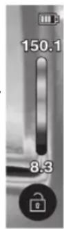
To determine the temperature of a specific area, move the measuring device so that the crosshairs with the temperature indication (m) are placed on the desired point or area. With automatic adjustment, the color spectrum of the scale is distributed linearly (= evenly) over the entire measurement range within the maximum or minimum temperature.
The measuring tool displays all measured temperatures in the measuring range in relation to each other. If heat is displayed bluish on the color palette in some areas, for example in a color representation, this means that the bluish areas belong to the cooler measured values in the current measuring range. However, these areas may still be in a temperature range that can cause injuries. Therefore, always pay attention to the displayed temperatures on the scale or directly at the crosshair.
Functions
Follow the information on navigating the individual menus (see "Navigating the individual menus", page 173)

Illumination of the measuring object
The measuring tool is equipped with a work light (4). It is intended to illuminate the direct work area of the measuring tool for image capture and does not serve as a permanent work light.
To switch the work light on/off, call up the left side bar. Navigate to the menu item / and confirm your selection. When the work light is switched on, the status bar is displayed.
The light automatically switches off after 2 minutes to avoid affecting measurement accuracy.
You can set the automatic switch-off time in the menu in .
Overlay of thermal and real image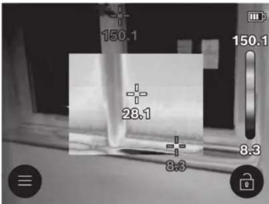
For better orientation (= spatial assignment of the displayed thermal image), you can additionally connect a visual real image for calibrated temperature ranges.
Note: The overlay of real and thermal image is completely accurate at a distance of 1 m. At different distances from the measuring object, there is a principle shift between the real and thermal image. This shift can be compensated using special Bosch apps. Information on the apps and their compatibility can be found on the product page of the measuring tool or at www.bosch-professional.com/thermal.
The measuring tool offers the following options:
- 100% infrared image
Only the thermal image is displayed.
The displayed thermal image is transparently overlaid on the real image. This allows objects to be recognized better.
To enable or disable the setting, open the left side bar and navigate to the menu item / . Confirm the selection by pressing the multifunction button (17) in the center.
- Picture-in-picture
The displayed thermal image is cropped and the surrounding area is shown as a real image. This setting improves the spatial assignment of the measured area.
To enable or disable the setting, open the left side bar and navigate to the menu item / . Confirm the selection by pressing the multifunction button (17) in the center.
Adjusting the color display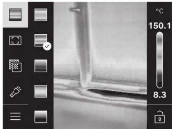
Depending on the measurement situation, different color palettes can make it easier to analyze the thermal image and display objects or situations more clearly on the screen. The measured temperatures are not affected by this. Only the display of temperature values changes.
To change the color palette, open the side bar and navigate to the menu item "Color palette". Confirm the selection by pressing the multifunction button (17) in the center.
Setting a fixed scale
The color distribution on the thermal image is adjusted automatically, but it can be stopped by pressing the multifunction button (17) to the right and then in the center. This allows comparison of thermal images taken under different temperature conditions (e.g., when searching for thermal bridges in multiple rooms) or when masking an extremely cold or hot object in the thermal image that would otherwise distort it (e.g., a heating element as a hot object when searching for thermal bridges).
To switch the scale back to automatic mode, open the right side bar and press the multifunction button (17) in the center. The temperatures now behave dynamically again and adapt to the measured minimum and maximum values.
Main menu
Open the left side bar (see "Navigation to the individual menus", page 173). To go to the main menu, press the multifunction button (17) in the center.
- In this menu item you can delete saved images individually or all at once.
-
- (a)
For several of the most commonly used materials, emission levels are stored for selection. To make searching easier, the values are summarized into groups in the emission levels catalog. In the <Material Catalog> menu, first select the appropriate category and then the appropriate material. If you know the exact emission level of your measured object, you can also set it as a numerical
value in the menu item.
Setting this parameter can improve the measurement result, especially for materials with low emission levels (= high reflection). In some situations (especially indoors), the reflected temperature corresponds to the ambient temperature. If objects with significantly different temperatures near highly reflective objects can affect the measurement, you should adjust this value. Press the multifunction button (17) left or right.
-
To ensure high accuracy over the entire measurement range, measurements are taken in 2 temperature ranges. In the measuring function
the device automatically selects the appropriate temperature range based on the temperature distribution in the thermal image. It evaluates how many measured values lie above a certain temperature threshold. If very small but hot objects are measured, a low temperature range may be selected, which is unsuitable for high temperatures. This can be recognized by the preset symbol \~ on the temperature indication. In such a case, switch to the measuring function <100 °C ... 450 °C> or <-20 °C ...
100 °C>, in which the color distribution corresponds to the set temperature range. The setting is indicated on the scale by an arrow up or down.
The measuring instrument automatically selects the appropriate temperature range based on the temperature distribution in the thermal image. It evaluates how many measured values lie above a certain temperature threshold. If very small but hot objects are measured, a low temperature range may be selected, which is unsuitable for high temperatures. This can be recognized by the preset symbol \~ on the temperature display. In such a case, switch to the measuring function <100 °C ... 450 °C> or <-20 °C ...
(m): / This point is displayed in the center of the thermal image and shows the measured temperature value at that location. • (n): /
The hottest point (= measuring pixel) is marked with a red crosshair on the thermal image. This facilitates the search for critical spots (e.g., loose contact terminals in a distribution board).
- (m): / This point is displayed in the center of the thermal image and shows the measured temperature value at that location. • (n): /
The coldest point (= measuring pixel) is marked with a blue crosshair on the thermal image. This facilitates the search for critical spots (e.g., leaks on a window).
The coldest point (= measuring pixel) is marked as a blue crosshair on the thermal image. This makes it easier to find critical spots (e.g., leaks in a window).
• (i): / - (c): /
The average temperature (°C) is displayed at the top left of the thermal image (the average temperature of all measured values on the thermal image). This can make it easier to determine the reflected temperature.
-
-
In this menu item, you can adjust the brightness of the display lighting.
•
In this menu item, you can select the time interval for the automatic shutdown of the work light when no button is pressed.
•
In this menu item, you can select the time interval after
which the measuring instrument automatically switches off when no button is pressed. You can also deactivate the automatic shutdown by selecting the setting .
•
In this extended menu, in addition to setting the time and date, you can also change their current format.
•
In this menu item, you can select the language used on the display.
•
In this menu item, you can reset the measuring tool to factory settings and permanently delete all data. This may take several minutes. Press the multifunction button (17) on the right to delete all files, or the multifunction button (17) on the left to cancel the process.
-
In this menu item, you can retrieve information about the measuring tool. You will find the serial number of the measuring tool and the version of the installed software. You will also find additional information about the measuring tool and software updates.
To exit any menu and return to the standard display on the screen, you can also press the Measurement button (6).
Software update for the measuring tool
If necessary, you can update the software of the measuring tool via the USB Type-C® interface. Relevant information can be found at:
www.bosch-professional.com/thermal-update.
Documenting measurement results
Saving measurement results to memory
Immediately after switching on, the measuring tool starts measuring and continues to do so continuously until it is switched off.
To save an image, point the camera at the desired measuring object and press the Measurement button (6). The image is saved to the internal memory of the measuring tool. The measurement is frozen and displayed on the screen. This allows thorough inspection of the image and subsequent adjustments (e.g., color palette). If you do not want to save the frozen image, restart the measuring mode using the Measurement button (6). To save the image to the internal memory of the measuring tool, press the multifunction button (17) in the center.
Recalling saved images
To recall saved thermal images, proceed as follows:
– Immediately after saving, press the multifunction button (17) in the center again. The preview of the last saved photo will appear on the display. - Alternatively, you can view saved photos in the menu item. - To switch between saved thermal images, press the multifunction button (17) on the right or left.
In addition to the thermal image, a visual image was also saved. To view it, press the multifunction button (17) up or down.
After 5 seconds, the measuring instrument switches to full-screen view. In full-screen view, the display of the main bar is turned off so that you can examine all the details of the thermal image.
Press the multifunction button (17) up or down to switch between views.
Deleting saved images
To delete individual or all thermal images, press the multifunction button (17) in the center. The extended menu opens.
- Here you can choose whether to delete only this image or all images. Confirm the selection with the multifunction button (17) in the center.
When selecting, you can choose between and <Cancel>. Confirm the selection with the multifunction button (17) in the center.
- In this extended menu, you can also view information about the emissivity and reflected temperature.
Image data fragments remain in memory and could be reconstructed. For definitive deletion, select in the main menu → <Factory
settings>.
Data transfer
Data transfer via USB interface
Open the cover (11) of the USB Type-C® socket. Connect the USB Type-C® socket (12) of the measuring instrument to the computer using the supplied USB Type-C® cable (16).
Now turn on the measuring instrument with the power button (18).
Open the file browser on the computer and select the drive GTC_450. You can copy, move to the computer, or delete the stored files from the internal memory of the measuring instrument.
After completing the desired action, disconnect the drive from the computer in the standard way, and then turn off the measuring instrument again using the power button (18).
Caution: Always disconnect the drive from the operating system first (eject the drive), otherwise the internal memory of the measuring tool may be damaged.
Remove the USB Type-C® cable and close the cover (11).
Always keep the USB interface cover closed to prevent dust or splashing water from entering the housing.
Warning: Connect the measuring tool to a computer via USB only. Connecting to other devices may damage the measuring tool.
Warning: The USB Type-C® interface is for data transfer only. It cannot be used to charge batteries or rechargeable batteries.
Post-processing of thermal images
You can post-process stored thermal images using special Bosch apps. Information about the apps and their compatibility can be found on the product page of the measuring tool or at
www.bosch-professional.com/thermal.
Errors – causes and remedies
In the event of a malfunction, the measuring tool restarts and can then be used again. Otherwise, the following overview will help you with persistent error messages.
Error Cause Remedy
| Merací prístroj sa nedá za-pnút. | Vybitý akumulátor/batérie Nabite akumulátor alebo vymeňte batérie. | |
 | Chyba akumulátora/batérií Vymeňte akumulátor, príp. batérie. | |
 | Akumulátor/batérie sú príliš teplé alebo príliš studené | |
 | Merací prístroj je príliš teplý alebo príliš studený | |
 | USB prípojka alebo USB kábel sú chybné | |
Error Cause Remedy
The measuring tool cannot be connected to the computer.
Note: Always use the supplied USB cable.
Flat battery Replace the button battery (see "Replacing the button battery (see Figure C)", page 178). Confirm the replacement with "OK" by pressing the multifunction button (17) in the center.
Explanation of terms
Further information can be found at www.bosch-professional.com/thermal.
Infrared thermal radiation
Infrared thermal radiation is electromagnetic radiation emitted by every body above 0 Kelvin (-273 °C). The amount of radiation depends on the temperature and the emissivity of the body.
Emissivity
The emissivity of an object depends on the material and structure of its surface. It indicates how much infrared thermal radiation the object emits compared to an ideal thermal radiator (black body, emissivity ε = 1) and therefore represents a value from 0 to 1.
Thermal bridge
The term thermal bridge refers to a location on the exterior wall of a building where there is a locally greater heat loss through the structure.
Thermal bridges can cause an increased risk of mold.
Reflected temperature/reflectivity of the object
Reflected temperature is thermal radiation that does not originate from the object itself. Depending on the structure and material, ambient radiation is reflected from the measured object and thus distorts its own resulting temperature.
Object distance
The distance between the measured object and the measuring instrument affects the captured area size per pixel. As the object distance increases, you can capture increasingly larger objects.
| Vzdialenost (m) Vel'kost infračerveného pixelu (mm) | Infračervená oblast šírka × výška (m) |
| 0,30 1,14 ~ 0,29 × 0,22 | |
| 0,55 2,08 ~ 0,53 × 0,40 | |
| 1,00 3,79 ~ 0,97 × 0,73 | |
| 2,00 7,58 ~ 1,94 × 1,46 | |
| 5,00 18,95 ~ 4,85 × 3,64 |
Maintenance and service
Maintenance and cleaning
Always store and transport the measuring tool only in a suitable box, such as the original packaging.
Always keep your measuring tool clean. A dirty infrared sensor (5) can impair measurement accuracy.
No liquid must get into the measuring tool during cleaning.
Do not attempt to remove dirt from the infrared sensor (5), camera (3), work light (4), or laser outlet opening (2) with sharp objects. Do not wipe the infrared sensor or camera (risk of scratching).
Clean especially the surfaces at the outlet opening regularly and make sure to remove any trapped fabric fibers.
If you need to recalibrate the measuring tool, contact an authorized Bosch service center.
If repair is necessary, send the measuring tool in its original packaging.
The measuring tool contains no parts that require user maintenance. Opening the housing may destroy the measuring tool.
Replacing the button battery (see figure C)
Open the cover (11)
Unscrew the screw (10) of the button battery holder. Pull the button battery holder (9) out of the measuring tool. Replace the button battery. After inserting the button battery holder, retighten the screw (10).
Customer service and usage advice
Customer service will answer your questions regarding repair and maintenance of your product as well as spare parts. Exploded views and information on spare parts can also be found at: www.bosch-pt.com
The Bosch advisory team will be happy to help you with questions regarding our products and their accessories. In case of any questions or spare parts orders, please always specify the 10-digit article number given on the product's type plate.
Slovakia
You can order the repair of your machine or spare parts online at www.bosch-pt.sk.
Tel.: +421 2 48 703 800
Fax: +421 2 48 703 801
E-Mail: servis.naradia@sk.bosch.com
www.bosch-pt.sk
Further service addresses can be found at:
www.bosch-pt.com/serviceaddresses
Transport
Recommended lithium-ion batteries are subject to the requirements for the transport of dangerous goods. The user can transport these batteries by road without further measures.
When sending via third parties (e.g., by air transport or forwarding agency), special requirements for packaging and labeling of the consignment must be observed. In such a case, an expert for the transport of dangerous goods must be consulted without fail when preparing the consignment.
Only send batteries if their packaging is not damaged. Tape over open contacts and pack the battery so that it cannot move around in the packaging. Please also observe any further national regulations.
Disposal
Measuring instruments, batteries, accessories, and packaging should be recycled in an environmentally friendly manner.

Devices, batteries, accessories, and packaging must be recycled in an environmentally responsible manner.
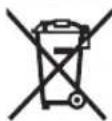
Do not dispose of measuring instruments and rechargeable batteries/batteries in household waste!
Only for EU countries:
Measuring instruments that are no longer suitable for use, and damaged or used rechargeable batteries/batteries must be disposed of separately. Use designated collection systems for this purpose. In the event of incorrect disposal, old electrical and electronic products may have harmful effects on the environment and human health due to the possible presence of hazardous substances.
Rechargeable batteries/batteries:
Li-Ion:
Follow the instructions in the "Transport" section (see "Transport", page 178) as necessary.
Hungarian
Safety Information

Read and follow all instructions to handle the measuring tool safely and without danger. If the measuring tool is not used in accordance with the supplied instructions, this may affect the protective measures built into the measuring tool. Never make warning signs on the measuring tool unrecognizable. KEEP THESE INSTRUCTIONS IN A SAFE PLACE, AND IF YOU PASS THE MEASURING TOOL ON, PASS THESE INSTRUCTIONS ON AS WELL.
Caution – if you use operating or control devices other than those specified here, or procedures other than those specified here, this can lead to dangerous radiation exposure.
The measuring tool is delivered with a laser warning sign (this is marked in the illustration of the measuring tool on the graphics page). If the text on the laser warning sign is not in your language, before first use stick the self-adhesive label supplied with the device over it, which contains the text in the language used in your country.
Do not direct the laser beam at other persons or animals, and do not look into the direct or reflected laser beam yourself. Otherwise, you may blind persons, cause accidents, and injure the eyes of the person concerned.
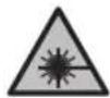
Do not point the laser beam at other people or animals, and do not look into the direct or reflected laser beam yourself. Otherwise, you may blind people, cause accidents, and injure the eyes of the person concerned.
If your eyes are exposed to laser radiation, close your eyes and immediately step out of the laser beam. ▶ Do not make any modifications to the laser device. Do not use the laser viewing glasses (separate accessory) as protective goggles. The laser viewing glasses are intended to make it easier to recognize the laser beam, but they do not protect against it. Do not use the laser viewing glasses (separate accessory) as sunglasses or for road traffic. The laser viewing glasses do not provide full protection against ultraviolet radiation and reduce color recognition ability. Have the measuring tool serviced only by qualified personnel and only with original spare parts. This ensures that the measuring tool remains safe. ▶ Do not allow children to use the laser measuring tool without supervision. They may unintentionally blind themselves or others. ▶ Do not work with the measuring tool in explosive environments where flammable liquids, gases, or dusts are present. The measuring tool may create sparks that could ignite the dust or vapors. ▶ Do not modify or open the battery. There is a risk of short circuit. If the battery is damaged or improperly handled, vapors may be released. The battery may catch fire or explode. Immediately provide fresh air and consult a doctor if you experience any symptoms. The vapors may irritate the respiratory tract. In case of misuse or damage, flammable liquid may escape from the battery. Avoid contact with the liquid. If accidental contact occurs, rinse the affected area with water immediately. If the liquid gets into your eyes, also seek medical attention. Escaping battery liquid may cause irritation or burns. The battery can be damaged by sharp objects such as pins or screwdrivers, or by external impact. An internal short circuit may occur and the battery may catch fire, emit smoke, explode, or overheat.
Keep the battery away from any metal objects, such as paper clips, coins, keys, nails, screws, and other small metal objects that could bridge the contacts. A short circuit between the battery contacts can cause burns or fire. - Use the battery only in products from the manufacturer. Only in this way can the battery be protected against dangerous overload. Charge the battery only with chargers recommended by the manufacturer. If a charger intended for a specific battery type is used with a different battery, a fire may occur.
Keep the battery away from any metal objects, such as paper clips, coins, keys, nails, screws, and other small metal objects that could bridge the contacts. A short circuit between the battery contacts can cause burns or fire. - Use the battery only in products from the manufacturer. Only in this way can the battery be protected against dangerous overload. Charge the battery only with chargers recommended by the manufacturer. If a charger intended for a specific battery type is used with a different battery, a fire may occur.

Protect the power tool from heat, such as prolonged exposure to sunlight, fire, dirt, water, and moisture. There is a risk of explosion and short circuit.
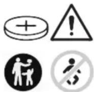
WARNING
Never swallow a button cell or insert it into any other body opening. If there is any suspicion that someone has swallowed or inserted a button cell into another body opening, seek medical attention immediately. Swallowing a button cell can cause severe or fatal internal injuries within 2 hours. ▶ When replacing the button cell, ensure it is replaced properly. There is a risk of explosion. Only use the button cells listed in this operating manual. Do not use other button cells or other power sources. ▶ Do not attempt to recharge or short-circuit the button cells. The button cell may leak, explode, catch fire, and cause personal injury. Exhausted button cells must be removed and disposed of in accordance with regulations. Exhausted button cells may leak and thus damage the product or cause personal injury. ▶ Do not overheat or throw button cells into fire. The button cell may leak, explode, catch fire, and cause personal injury. ▶ Do not damage or disassemble the button cell. The button cell may leak, explode, catch fire, and cause personal injury. Ensure that a damaged button cell does not come into contact with water. If leaking lithium comes into contact with water, hydrogen may be generated, which can lead to fire, explosion, or personal injury.
▶ Do not continue to use the measuring tool if the button cell compartment cannot be closed properly and completely. Remove the button cell and have the measuring tool repaired. Within a thermal image, high temperature differences can cause even high temperatures to be displayed in a color that someone might easily mistake for a low temperature. Touching such a surface can lead to burns. Correct temperature measurements are only possible if the set emissivity and the object's emissivity match. It is possible that the displayed temperature of objects is too high or too low, which poses a danger when touching these objects. ▶ Do not point the measuring tool directly at the sun or a high-power CO₂ laser. This can lead to damage to the detector. Protect the measuring tool, especially the camera and infrared lens area, from moisture, snow, dust, and dirt. The receiving lens may fog up or become dirty and falsify the measurement results. Incorrect adjustment of the instrument, as well as additional atmospheric influencing factors, can lead to incorrect measurement results. It is possible that the displayed temperature of objects is too high or too low, which poses a danger when touching these objects.
Product description and performance
Please observe the figures in the first part of the operating instructions.
Intended use
This thermal camera is intended for non-contact measurement of surface temperatures.
The displayed thermal image shows the temperature distribution in the field of view of the thermal camera, thus allowing temperature differences to be represented in different colors.
With proper use, temperature differences and anomalies on surfaces and objects can be examined without contact, and components and/or their possible defects can be made visible, etc.:
– Thermal insulation and insulation (e.g., locating thermal bridges) – Active heating and hot water pipes laid in floors and walls (e.g., underfloor heating) – Overheated electrical components (e.g., fuses or terminals) – Damaged or faulty components (e.g., overheating due to a defective ball bearing).
The measuring tool is not suitable for measuring the temperature of gases.
The measuring tool must not be used for medical purposes on humans.
For veterinary applications, please refer to the website www.bosch-professional.com/thermal.
The measuring tool can be used both indoors and outdoors.
This product is a laser product that complies with EN 50689 and is available in retail.
The lamp of the measuring tool is intended to illuminate the immediate work area for taking images, not as a permanent work light.
The point laser must not be used as a laser pointer. It is only for marking the measurement surface.
Components shown in the figures
The numbering of the illustrated components corresponds to the illustration of the measuring tool on the page with figures.
(1) Protective cap (2) Laser beam exit opening (3) Visual camera (4) Work light (5) Infrared sensor (6) Measurement pause/start button (7) Battery compartment (8) Laser warning label (9) Button cell holder (10) Button cell holder screw (11) USB socket and button cell holder cover (12) USB Type-C® socket a) (13) Laser button (15) Battery b) (16) USB Type-C® cable b)
(14) Battery/adapter release button
(17) Multi-function button (18) On/off button/back button (19) Display (20) Serial number (21) Adapter case (22) Batteries b) (23) Adapter cap a) USB Type-C® and USB-C® are trademarks of USB Implementers Forum. b) Accessories shown in the images or described in the text are not all included in the standard delivery.
Display elements
(a) Emission factor display (b) Reflected temperature display (c) Average temperature display (d) Memory full symbol (e) Work light symbol (f) Laser symbol (g) Charge status display (h) Display of maximum surface temperature in the measuring area (i) Scale (j) Display of minimum surface temperature in the measuring area (k) Temperature scale lock symbol (l) Cold spot display (example) (m) Crosshair with temperature display (n) Hot spot display (example) (o) Menu symbol
Technical data
| Hökamera GTC 12V-450-13 | |
| Cikkszám | 3 601 K83 900 |
| Az infravörös érzékelő felbontása 256 × 192 pixel | |
| HöérzékenységA) | ≤ 50 mK |
| Spektrális terület 8–14 μm | |
| Látómező (FOV)A) | 55,6° × 42° |
| térbeli felbontás (IFOV) 3,79 mrad | |
| FókusztávolságA) | ≥ 0,5 m |
| Fókusz rögzített | |
| Hökép frissítési gyakorisága ≤ 9 Hz | |
| Felületi hőmérséklet mérési tartományA) | -20 ... +450 °C |
| Felületi hőmérséklet mérési pontosságaA(B)C) | |
| >0 °C ... ≤ +100 °C) | ±2 °C |
| >+100 °C) | ±2% |
| Hőmérséklet-felbontás 0,1 °C | |
| Kijelzőtípus TFT | |
182 | English
Thermal camera GTC 12V-450-13
| Kijelző mérete 2,8" | |
| Kijelző felbontása 480 × 360 px | |
| Beépített vizuális kamera felbontása 2 MP (640 × 480 px) | |
| Képformátum .jpg | |
| Mentésenként mentett képek száma 1 × hökép (képernyőkép) | 1 × vizuális valós kép hömérséklet értékekkel együtt (meta-adatok) |
| A képek max. száma a belső képtároló memóriában 500 | |
| A használathoz megengedett max. tengerszint feletti magas-ság | 2000 m |
| Szennyezettségi fok az IEC 61010-1 szerint 2 | F) |
| A levegő max. relativ nedvességtartalma.A) | 90% |
| Lézerosztály 2 | |
| Lézertípus < 1 mW, 645–660 nm | |
| A lézersugár széttartása 1,5 mrad (teljes szög) | |
| Energiaellátás | |
| - akkumulátor (Li-ion) 12 V | |
| - elemek (alkáli-mangán, akkuadapterrel) 4 × 1,5 V LR6 (AA) | |
| - akkumulátorok (NiMH, elemadapterrel) 4 × 1,2 V HR6 (AA) | |
| ÜzemidőG) | |
| - akkumulátor (Li-ion)H) | 8 h |
| - elemek (alkáli-mangán) 4 h | |
| A rendszeridő energiaellátása CR1225 (3 V-os lítium-elem) | |
| USB-Standard | 2.0 |
| USB-interfész | USB Type-C® |
| SúlyJ) | 0,354 kg |
| Méretek (hosszúság × szélesség × magasság)K) | 89 × 79 × 209 mm |
| Védettség (az akkumulátor/elemek kivételével, álló helyzet-ben) | IP54 |
| Javasolt környezeti hömérséklet a töltés során | 0 °C...+35 °C |
| Megengedett környezeti hömérséklet tárolás közben | |
| - üzem közben | -10 °C...+50 °C |
| - akkumulátorral való tárolással | -20 °C...+50 °C |
| - akkumulátor nélküli tárolással | -20 °C...+70 °C |
| Javasolt akkumulátorok | GBA 12V... |
Thermal camera GTC 12V-450-13
Recommended charging devices GAL 12...
GAX 18...
A) According to VDI 5585 standard (average value) B) At 20–23 °C ambient temperature and > 0.95 emission factor, measuring distance: 1 m, operating time: > 5 minutes, aperture 150 mm, with work light and laser switched off C) Plus application-dependent deviation (e.g., reflection, distance, ambient temperature) D) Valid for the center point, for all other pixels ±1 °C E) Valid for the center point, for all other pixels ±1% F) Only if non-conductive contamination occurs, although occasionally due to condensation, a temporary non-zero conductivity may be expected. G) With work light switched off and medium display brightness H) Depending on the battery used I) At 20-30 °C ambient temperature J) Weight without battery/battery adapter/batteries K) With GBA 12V 2.0Ah battery or battery adapter. Your measuring tool can be clearly identified by the serial number (20) on the type plate.
Power supply for the measuring tool
The measuring tool can be operated either with a Bosch Li-ion battery, with commercially available batteries, or with commercially available NiMH rechargeable batteries.
Operation with battery (see figure A)
Only use the charging devices specified in the Technical Data. Only these charging devices are precisely matched to charge the lithium-ion batteries used in your measuring tool.
Note: Lithium-ion batteries are shipped partially charged according to international transport regulations. To ensure full battery performance, fully charge the battery before first use.
To insert the charged battery (15), push it into the battery compartment (7) until it audibly clicks into place.
To remove the battery (15), press the release buttons (14) and pull the battery out of the battery compartment (7). Do not force it out.
Operation with batteries (see figure B)
For operating the measuring tool, we recommend using alkaline manganese batteries or NiMH rechargeable batteries.
The batteries must be inserted into the battery adapter.
The battery adapter is intended exclusively for use in Bosch measuring tools designed for this purpose and must not be used with power tools.
To insert the batteries, slide the battery adapter (21) housing into the battery compartment (7). Insert the batteries into the housing as shown in the figure on the closing cap (23). Slide the closing cap onto the housing until it audibly clicks into place.
To remove the batteries (22), press the release button (14) on the closing cap (23) and pull off the closing cap. Remove the batteries. To remove the inner housing (21) from the battery compartment, reach into the housing and apply some pressure to the side wall, then pull the housing out of the measuring tool.
Always replace all batteries or rechargeable batteries at the same time. Only use batteries or rechargeable batteries of the same capacity from the same manufacturer.
▶ Remove the batteries or rechargeable batteries from the measuring tool if it will not be used for an extended period. During prolonged storage, the batteries and rechargeable batteries may corrode in the measuring tool.
Information on optimal handling of the battery
Protect the battery from moisture and water.
The battery should only be stored within a temperature range of -20°C to 50°C. For example, do not leave the battery in a vehicle in summer.
If the device can only be operated for a significantly shorter time after charging the battery, the battery is worn out and must be replaced.
Observe the regulations concerning the disposal of waste.
Operation
- Protect the measuring tool from moisture and direct sunlight. Do not expose the measuring tool to extreme temperatures or temperature fluctuations. For example, do not leave it in a car for extended periods. In case of large temperature fluctuations, wait until the measuring tool has acclimatized before putting it into operation. In case of extreme temperatures or temperature fluctuations, the accuracy of the measuring tool may be reduced.
184 | Hungarian
Ensure that the measuring tool acclimatizes properly. In case of strong temperature fluctuations, the acclimatization time can be up to 60 minutes. This can occur, for example, if the measuring tool is stored in a cold vehicle and then used for a measurement in a warm building. Make sure that the measuring tool does not fall and is not exposed to strong shocks or impacts. After strong external impacts or in case of noticeable irregularities during operation, have the measuring tool checked by an authorized Bosch customer service.
Operation
Initial Operation
When the measuring tool is switched on for the first time, or after resetting to factory settings, some basic settings must be made. Select the desired values by pressing the upper, lower, left, or right part of the multi-function button (17). Confirm the selected value by pressing the center of the multi-function button (17). After confirming the selected value, the next setting appears on the display. The status bar at the top shows all settings and the number of remaining settings.
The following basic settings are available:
Switching On and Off
For measuring, fold up the protective cap (1). Ensure that the infrared measuring area is not blocked or covered during work.
To switch on the measuring tool, press the On/Off button (18). A start-up sequence appears on the display (19). After the start-up sequence is complete, the measuring tool immediately begins measuring and continues to do so until it is switched off.
Note: During the first few minutes, the measuring tool may perform automatic equalization more frequently, as the sensor head temperature and the ambient temperature have not yet become identical. Repeated sensor equalization ensures that precise measurements can be performed.
During this time, the \~ symbol may appear next to the temperature display. This phenomenon is intensified in case of strong fluctuations in ambient temperature. Therefore, switch on the measuring tool a few minutes before starting the measurement, if possible, so that its temperature can stabilize.
To switch off the measuring tool, keep the On/Off button (18) pressed for > 1 s. The measuring tool then saves all settings and switches off. For safe transport, close the protective cap (1).
In the main menu, you can select whether the measuring tool should switch off automatically after a certain time, and if so, after how long (see "Main menu", page 186).
If the battery or the measuring tool is outside the operating temperature range specified in the Technical Data, the measuring tool will automatically switch off after a brief warning (see "Faults – Causes and Corrective Measures", page 188). Wait until the temperature of the measuring tool has returned to normal, then switch it on again.
Navigating in the various menus
Navigating in the various menus of the measuring tool:
- Displaying the menu bars: press the center or left side of the multi-function button (17). The menu bars appear on the right and left of the display, with the main menu highlighted.
- Scrolling through the left menu bar/navigating in the main menu: press the top, bottom, left, or right side of the multi-function button (17). – Switching to the right menu bar: press the left or right side of the multi-function button (17). – Confirming the selection/switching to a submenu: press the center of the multi-function button (17). – Going back from a submenu to a higher-level menu: press the Back button (18).
Preparing for measurement
Setting the emission factor for surface temperature measurements
The emission factor of an object depends on the material and the surface structure. The factor indicates how much infrared heat radiation an object emits compared to an ideal heat radiator (black body, emission factor € = 1); accordingly, the factor value is between 0 and 1.
To determine the surface temperature, the natural infrared heat radiation emitted by the target object is measured without contact. To ensure correct measurements, the emission factor set on the measuring tool must be checked before each measurement and, if necessary, readjusted to match the object being measured.
The emission factors preset in the measuring tool are reference values.
Here you can select one of the preset emission factors or enter a precise numerical value. Set the desired emission factor in the → menu (see "Main menu", page 186).
▶ Correct temperature measurements are only possible if the set emission factor matches the emission factor of the object.
The lower the emission factor, the greater the influence of the reflected temperature on the measurement result. Therefore, when changing the emission factor, always set the reflected temperature accordingly. Set the reflected temperature in the → menu (see "Main menu", page 186).
Apparent temperature differences displayed by the measuring tool can be attributed either to actual temperature differences or to different emission factors.
In the case of strongly differing emission factors, the displayed temperature differences can deviate significantly from the actual values.
If there are multiple objects made of different materials or with different structures in the measuring area, the displayed temperature values are only accurate for the set emissivity. For all other objects (whose emissivity differs from the set value), the displayed color differences can be treated as information indicating the relationships between temperatures.
Measurement conditions
Highly reflective or shiny surfaces (e.g., glossy tiles or bare metals) can significantly distort or influence the displayed results. If necessary, cover the measuring surface with a dark, matte adhesive tape that is a good heat conductor. Allow the tape to acclimate on the surface for a short time.
For highly reflective surfaces, ensure a favorable measuring angle to prevent heat radiation reflected from other objects from distorting the result. For example, in measurements taken perpendicularly from the front, the radiation of your body heat can interfere with the measurement. In the case of a flat surface, the contours and temperature of your own body (reflected value) may be displayed, which does not correspond to the actual temperature of the measured surface (emitted emissivity value or the actual value of the surface).
Therefore, it is fundamentally impossible to perform such measurements through transparent materials (e.g., glass or transparent plastics).
The measurement results are more accurate and reliable the better and more stable the measurement conditions are. The accuracy of the measurement is influenced not only by environmental conditions and strong ambient temperature fluctuations but also by strong fluctuations in the temperature of the object being measured.
The result of infrared temperature measurement is also influenced by smoke, steam/high humidity in the air, or dusty air.
Notes for increasing measurement accuracy:
- Get as close to the object being measured as possible to minimize interfering factors between you and the measuring surface.
- Before measuring, ventilate indoor areas, especially if the air is polluted or has very high humidity. After ventilating, wait until the room reaches its normal temperature again.
Marking the measuring spot
▶ Do not point the light beam at people or animals and do not look directly into the laser beam yourself – even from a greater distance.
The measuring tool is equipped with a laser for marking the measuring spot.
Press and hold the laser button (13). The laser symbol (f) appears on the status bar, and a red circle appears around the crosshair (m). The laser and the crosshair coincide exactly at a distance of 1 m.
When you release the laser button (13), the laser turns off.
Assigning temperatures using the scale
The (i) scale is located on the right side of the display. The values at the top and bottom of the scale are set according to the highest (h) and lowest (j) temperatures defined in the thermal image. 99.99% of the pixels are evaluated for the scale. The assignment of colors to temperature values is uniform (linear) in the image.
Using the different color shades, the temperature can thus be determined by color between these two extreme values. For example, the temperature that lies exactly between the highest and lowest values is assigned to one of the colors in the middle color range.
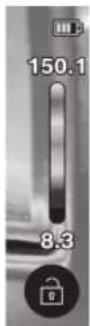
To determine the temperature of a specific area, move the measuring device so that
the (m) crosshair with the temperature display points to the desired point or area. In automatic adjustment mode, the color spectrum of the scale is always divided linearly (= evenly) between the highest and lowest temperatures of the entire measurement area.
The measuring tool displays the temperatures measured within the measurement area relative to each other. If an area appears in a blue shade in the color image, this means that this area is among the relatively cooler areas within the given measurement area. However, these areas may still have temperatures high enough that touching them poses a risk of injury. Therefore, always pay attention to the temperature values displayed on the scale or directly at the crosshair.
Functions
Observe the information on navigating through the various menus (see "Navigating in the various menus", page 184).

Illuminating the measured object
The measuring tool is equipped with a work light (4). It is used to illuminate the immediate work area of the measuring tool for image capture, not as a permanent work light.
To switch the work light on or off, open the side bar. Navigate to the / menu item and confirm the selected value. If the work light is switched on, this is shown in the status bar.
The light switches off automatically after 2 minutes to avoid affecting the accuracy of the measurement.
The automatic switch-off time can be set in the menu under settings.
Overlay of thermal image and real image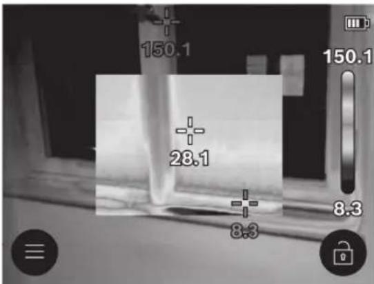
To facilitate orientation (= assignment of the displayed thermal image to the actual scene) in cases of balanced temperature ranges, a visual image can additionally be switched on for the display.
Note: The real image and the thermal image coincide exactly at a distance of 1 m. For distances other than this from the object being measured, a certain offset occurs between the real image and the thermal image, in accordance with the measurement principle. This offset can be compensated for with special Bosch applications. Information about the applications and compatibility can be found on the product page of the measuring tool or at
www.bosch-professional.com/thermal.
The measuring tool offers the following options:
- 100% infrared image
In this mode, only the thermal image is displayed.

- Transparent display
The displayed thermal image is projected onto the real image in a transparent form. This makes objects easier to recognize.
To activate/deactivate this setting, load the left sidebar and navigate to the /
menu item. Confirm the selected value by pressing the center of the multi-function button (17).
- Picture-in-picture
The edges of the displayed thermal image are cut off, and the surrounding area is shown as a real image. This setting makes it easier to assign the measurement area to the real image.
To activate/deactivate this setting, load the left sidebar and navigate to the / menu item. Confirm the selected value by pressing the center of the multi-function button (17).
Setting the color display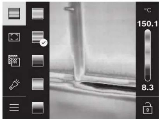
Depending on the measurement situation, different color scales can make it easier to analyze the thermal image and display the situation more clearly on the screen. The choice of color scale has no influence on the measured temperatures. Selecting the color scale essentially only changes the representation of the temperature values.
To switch the color palette, load the sidebar and navigate to the color palette menu item. Confirm the selected value by pressing the center of the multi-function button (17).

Fixing the scale
The assignment of the color distribution to the thermal image is done automatically, but it can be fixed by pressing the multifunction button (17) on the right side and then in the middle. This makes it possible to compare thermal images taken under different temperature conditions (e.g., if you examine several rooms one after the other for the presence of thermal bridges) or to hide a particularly cold or hot object (such as a heater when searching for thermal bridges) that would otherwise falsify the results.
To reset the scale to automatic, load the right-hand bar and press the multifunction button (17) in the middle. The temperatures now change dynamically again and adjust according to the measured maximum and minimum values.
Main menu
Load the left-hand bar (see "Navigating in the different menus", page 184). Enter the main menu by pressing the center of the multifunction button (17).
- In this menu item, you can delete the saved images all at once or individually.
-
• (a)
Stored emissivity factors are available for some of the most common materials. To make the search easier, the individual values in the emissivity factor catalog are grouped into categories. First select the appropriate category in the menu item, then the appropriate material. If you know
the exact emissivity factor of the object being measured, you can also set it as a numerical value in the menu item.
• (b)
Setting this parameter can improve the measurement results, especially for materials with a low emissivity factor (= high reflectivity). In certain situations (especially indoors), the reflected temperature corresponds to the ambient temperature. If objects with strongly different temperatures near highly reflective objects can influence the measurement, the conditions must be taken into account and the value adjusted accordingly. To do this, press the left or right side of the multifunction button (17).
-
To ensure high accuracy over the entire measuring range, measurement is carried out in 2 temperature ranges. In the measurement function, the measuring device selects the appropriate temperature range based on the temperature distribution of the thermal image. It evaluates how many measured values are above a certain temperature threshold. If very small but hot objects are to be measured, it is possible that the low temperature range is selected, which is not suitable for measuring high temperatures. This can be recognized by the \~ symbol in front of the temperature display. In this case, switch to the <100 °C ... 450 °C> or <-20 °C ... 100 °C> measurement function in which the color distribution corresponds to the set temperature range. The setting is indicated by an arrow pointing up or down on the scale.
-
The point (m) appears in the center of the thermal image and indicates the temperature value measured at that point.
The hottest point (= measurement pixel) is marked with a red crosshair on the thermal image. This makes it easier to identify a critical point (for example, a loose contact in a switch cabinet).
The coldest point (= measurement pixel) is marked with a blue crosshair on the thermal image. This makes it easier to identify a critical point (for example, a poorly insulated spot on a window frame).
The average temperature (c) is displayed in the upper left corner of the thermal image (this is the average of all temperatures measured within the thermal image). This can facilitate the determination of the reflected temperature.
In this menu item, you can adjust the brightness of the display illumination.
In this menu item, you can set how long the work lamp
takes to switch off automatically if no button is pressed.
In this menu item, you can select the time interval after which the measuring tool automatically switches off if no button has been pressed during that time. It is also possible to deactivate the automatic switch-off: to do so, select the corresponding setting.
In this submenu, in addition to setting the time and date, you can also change the format of the date and time.
In this menu item, you can set the display language.
In this menu item, you can reset the measuring tool to the factory settings and permanently delete all data. Under certain circumstances, this may take a few minutes. Then press either the right side of the multi-function button (17) if you want to delete all files, or the left side of the multi-function button (17) to cancel the process.
In this menu item, you can read information about the measuring tool. There you will find the serial number of the measuring tool and the installed software version. You will also find additional information about the measuring tool and about software updates.
To exit any menu and return to the standard display screen, you can also press the measuring button (6).
Updating the measuring tool software
If necessary, you can update the software of the measuring tool via the USB Type-C® interface. Further information can be found at www.bosch-professional.com/thermal.
Documenting measurement results
Saving measurement results
After switching on, the measuring instrument immediately starts measuring and continues to do so continuously until it is switched off.
To save an image, point the camera at the desired object and press the measurement button (6). The image is saved to the camera's internal memory. Measurement stops and the image appears on the display. You can then calmly view the image and, if necessary, adjust it afterwards (for example, by changing the color scale). If you do not want to save the frozen image, you can return to measurement mode by pressing the measurement button (6) again. If you want to save the image to the camera's internal memory, press the center of the multi-function button (17).
Retrieving saved images
To retrieve saved thermal images, perform the following steps:
- Immediately after saving, press the center of the multi-function button (17) again. The preview of the last saved photo appears on the display.
- The saved photos can also be displayed from the menu item.
- To switch between saved thermal images, press the right or left side of the multi-function button (17).
In addition to the thermal image, the visual image is also saved. To display it, press the top or bottom side of the multi-function button (17).
After 5 seconds, the measuring instrument switches to full-screen display. In full-screen display, the title bar disappears so that all details of the thermal image can be viewed precisely.
You can switch between views by pressing the top and bottom parts of the multi-function button (17).
Deleting saved images
To delete individual images, press the center of the multi-function button (17). A submenu then opens.
- Here you can choose whether to delete only this image or all images. Confirm the selection by pressing the center of the multi-function button (17). If you select <Delete all>, you can choose between that and other options. Confirm the selection by pressing the center of the multi-function button (17). – In this submenu, you can also view the values for emissivity and reflected temperature.
The data fragments of the images remain in memory and can be reconstructed. For permanent deletion, select → <Factory
Settings > option.
Data transfer
Data transfer via the USB interface
Open the cover of the USB Type-C® socket (11). Connect the USB Type-C® socket (12) of the measuring tool to your computer using the supplied USB Type-C® cable (16).
Now switch on the measuring tool using the on/off switch (18).
Open the file browser on your computer and select the GTC_450 drive. The files stored in the measuring tool can be copied, moved, or deleted from the internal memory of the measuring tool.
After completing the desired procedure, always disconnect the drive from the computer, then switch off the measuring tool again using the on/off switch (18).
Caution: Always remove the drive entry from the operating system first (eject the drive), otherwise the internal memory of the measuring tool may be damaged.
Pull out the USB Type-C® cable and close the cover (11). Always keep the USB interface cover closed to prevent dust or splashing water from entering the housing.
Note: Connect the measuring tool via USB only to a computer. Connecting to other devices may damage the measuring tool.
Note: The USB Type-C® interface is intended solely for data transfer. Batteries and rechargeable batteries cannot be charged via this interface.
Post-processing of thermal images
You can post-process saved thermal images using special Bosch applications. Information about the applications and compatibility can be found on the product page of the measuring tool or at www.bosch-professional.com/thermal.
Errors – causes and corrective measures
In the event of a malfunction, the device performs a restart and can then be used again. If an error message appears several times in succession, the overview below may help.
| A mérőműszert nem lehet be- Akkumulátor/elem lemerült Töltse fel az akkumulátort, illetve cserélje ki az elemeket. kapcsolni. |
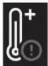
The measuring tool cannot be connected to a computer.
The USB connector or USB cable is damaged.
Check whether the measuring tool can be connected to another computer. If not, send the measuring tool to an authorized Bosch customer service center.
Note: Always use the USB cable supplied with the package.
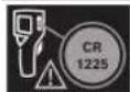
The button battery is discharged. Replace the button battery (see "Replacing the button battery (see Figure C)", page 189). Confirm the replacement by pressing OK or the center of the multi-function button (17).
Explanation of terms
Further information can be found at www.bosch-professional.com/thermal.
Infrared thermal radiation
Infrared thermal radiation is electromagnetic radiation emitted by all bodies with a temperature above 0 Kelvin (-273 °C). The amount of radiation depends on the body's temperature and emissivity.
Emissivity
The emissivity of an object depends on the material and surface structure. It indicates how much infrared thermal radiation an object emits compared to an ideal thermal radiator (black body, emissivity € = 1); the value is therefore between 0 and 1.
Thermal bridge
A location in the external wall of a building where, due to the construction properties, a locally higher heat loss occurs.
High humidity can increase the risk of mold formation.
Reflected temperature / reflective ability of an object
Reflected temperature is the thermal radiation that does not originate from the object itself. Depending on its structure and material, the object being measured reflects ambient radiation, which can distort the actual temperature measurement result.
Distance to the object
The distance between the object being measured and the measuring device affects the area covered per pixel. As the distance to the object increases, the temperature of larger objects can be determined.
| Távolság (m) Az infravörös pixel mérete (mm) | Szélesség × magasság, infravörös terület (m) |
| 0,30 1,14 ~ 0,29 × 0,22 | |
| 0,55 2,08 ~ 0,53 × 0,40 | |
| 1,00 3,79 ~ 0,97 × 0,73 | |
| 2,00 7,58 ~ 1,94 × 1,46 | |
| 5,00 18,95 ~ 4,85 × 3,64 |
Maintenance and service
Maintenance and cleaning
Store and transport the measuring device only in a suitable case, such as the original packaging.
Always keep the measuring device clean. A dirty infrared sensor (5) can negatively affect measurement accuracy.
During cleaning, no liquid should penetrate the measuring device.
Do not attempt to remove dirt from the infrared sensor (5), the camera (3), the work light (4), or the laser exit aperture (2) with sharp objects. Do not wipe the infrared sensor or the camera (risk of scratching).
Regularly clean the surfaces around the laser beam exit aperture and pay attention to any fibers.
If you wish to have your measuring device recalibrated, please contact an authorized Bosch customer service center.
If repair is needed, send the measuring device in its original packaging.
There are no user-serviceable parts inside the measuring device. Opening the device housing can lead to damage.
Replacing the battery (see figure C)
Open the cover (11).
Unscrew the screw of the battery holder (10). Pull the battery holder (9) out of the measuring tool. Replace the battery. Tighten the screw of the battery holder (10) again.
After-sales service and application advice
The after-sales service will gladly answer your questions regarding the repair and maintenance of your product, as well as spare parts. Exploded views and other information regarding spare parts can also be found at:
www.bosch-pt.com
The Bosch application advice team will be happy to help if you have questions about our products and their accessories.
If you have questions or would like to order spare parts, be sure to provide the 10-digit article number found on the product's type plate.
Hungary
Robert Bosch Kft.
1103 Budapest
Gyömrői út. 120.
You can order the repair of your device online at www.bosch-pt.hu.
Tel.: +36 1 879 8502
Fax: +36 1 879 8505
info.bsc@hu.bosch.com
www.bosch-pt.hu
Further service addresses can be found at:
www.bosch-pt.com/serviceaddresses
Transport
The recommended lithium-ion batteries are subject to dangerous goods regulations. Users can transport the batteries by road without further requirements.
If shipping is entrusted to a third party (e.g., air or other transport company), special requirements for packaging and labeling must be observed. In this case, a dangerous goods expert must be involved in preparing the shipment.
Only send the battery if its housing is not damaged. Tape over open contacts and pack the battery so it cannot move around inside the packaging. Please also observe any additional national regulations.
Disposal

Measuring tools, batteries/rechargeable batteries, accessories, and packaging materials must be recycled in an environmentally friendly manner.

Do not dispose of measuring tools and batteries/rechargeable batteries in household waste!
Only for EU member states:
Unusable measuring tools and defective or exhausted batteries/rechargeable batteries must be disposed of separately. Use the available collection systems.
In case of improper disposal, waste electrical and electronic equipment may have harmful effects on the environment and human health due to the potential presence of hazardous substances.
Batteries/rechargeable batteries:
Li-ion:
Please refer to the information in the Shipping chapter (see "Shipping", Page 190) function button.
Russian
For countries of the Eurasian Economic Union only
(Customs Union)
The operational documents provided by the manufacturer for the product may include this operating manual, as well as appendices.
Information on confirmation of conformity is contained in the appendix.
Information about the country of origin is indicated on the product body and in the appendix.
The date of manufacture is indicated on the last cover page of the Manual or on the product body.
Contact information regarding the importer is contained on the packaging.
Product service life
The service life of the product is 7 years. It is not recommended to operate after 5 years of storage from the date of manufacture without prior inspection (see the label for the date of manufacture).
List of critical failures and erroneous actions of personnel or user
– do not use if smoke appears directly from the product body
– do not use outdoors during rain (in sprayed water)
– do not switch on if water has entered the housing
Criteria for limit states
– the product housing is damaged
Type and frequency of maintenance
It is recommended to clean the tool from dust after each use.
Storage
– store in a dry place – store away from sources of high temperatures and exposure to sunlight – avoid sudden temperature changes during storage – if the tool is supplied in a soft bag or plastic case, it is recommended to store the tool in this protective packaging – for detailed storage conditions, see GOST 15150-69 (Condition 1)
Transportation
– dropping and any mechanical impact on the packaging during transportation is strictly prohibited – when loading/unloading, the use of any type of equipment that operates on the principle of clamping the packaging is not allowed
– for detailed transportation requirements, see GOST 15150-69 (Condition 5)
Safety instructions

To ensure safe and reliable operation of the measuring tool, all instructions must be read and followed. Using the measuring
tool not in accordance with these instructions may damage the integrated protective mechanisms. Never alter the warning labels on the measuring tool beyond recognition. KEEP THESE INSTRUCTIONS IN A SAFE PLACE AND PASS THEM ON WHEN TRANSFERRING THE MEASURING TOOL.
▶ Caution – the use of tools for servicing or adjustment or maintenance procedures other than those specified here may result in hazardous radiation exposure. The measuring tool is supplied with a laser radiation warning label (shown on the page with the image of the measuring tool). If the text on the laser radiation warning label is not in your native language, before first use, cover it with the sticker in your native language that is included in the scope of delivery.
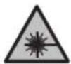
Do not point the laser beam at people or animals, and do not look directly into the laser beam or its reflection. This beam can blind people, cause accidents, or damage eyes.
▶ If the laser beam hits your eye, deliberately close your eyes and immediately turn away from the beam.
▶ Do not change anything in the laser device.
▶ Do not use the laser tool glasses (accessory) as protective glasses. Laser tool glasses improve laser beam recognition but do not protect against laser radiation.
Do not use the laser tool glasses (accessory) as sunglasses or while driving. Laser glasses do not provide UV protection and interfere with correct color perception.
Repair of the measuring tool may only be carried out by qualified personnel and only with original spare parts. This ensures the safety of the measuring tool.
▶ Do not allow children to use the laser measuring tool without supervision. Children
may accidentally blind themselves or others.
▶ Do not operate the measuring tool in explosive environments, near flammable liquids, gases, or dust. Sparks may be generated in the measuring tool, which could ignite dust or vapors. ▶ Do not make any modifications to the battery or open it. This poses a risk of short circuit. ▶ If the battery is damaged or used improperly, gas may be released. The battery may catch fire or explode. Ensure fresh air supply and consult a doctor if you experience any complaints. Gases may irritate the respiratory tract. ▶ If used incorrectly, liquid may leak from the battery. Avoid contact with it. In case of accidental contact, rinse the affected area with water. If this liquid gets into your eyes, also seek medical help. Leaking battery fluid may cause skin irritation or burns. ▶ Sharp objects such as nails or screwdrivers, as well as external force, can damage the battery. This may lead to internal short circuit, fire with smoke, explosion, or overheating of the battery. Protect the unused battery from paper clips, coins, keys, nails, screws, and other small metal objects that could short-circuit the poles. Short-circuiting the battery poles may cause burns or fire. - Use the battery only in products from the manufacturer. Only then is the battery protected against dangerous overload. Charge batteries only with chargers recommended by the manufacturer. A charger intended for a specific type of battery may pose a fire hazard when used with other batteries.

Protect the battery from high temperatures, e.g., prolonged exposure to sunlight, fire, dirt, water, and moisture. There is a risk of explosion and short circuit.
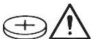
WARNING


Store miniature batteries out of the reach of children. Miniature batteries are unsafe.
▶ Miniature batteries must not be swallowed or inserted into any other natural body openings. If you suspect that a miniature battery has been swallowed or inserted through another natural body opening, seek medical attention immediately. Swallowing a miniature battery can cause severe internal burns and death within 2 hours. ▶ Replace the miniature battery properly. There is a risk of explosion. Use only the miniature batteries specified in this instruction manual. Do not use other miniature batteries or other power sources. ▶ Do not attempt to recharge the miniature battery or short-circuit it. The miniature battery may leak, explode, catch fire, and cause injury. Remove and dispose of discharged miniature batteries in accordance with the regulations. Discharged miniature batteries may leak and damage the product or cause injury. ▶ Do not heat the miniature battery or throw it into a fire. The miniature battery may leak, explode, catch fire, and cause injury. ▶ Do not damage or disassemble the miniature battery. The miniature battery may leak, explode, catch fire, and cause injury. Do not allow a damaged miniature battery to come into contact with water. Released lithium may react with the hydrogen in water, causing fire, explosion, or injury. Do not use the measuring tool if the miniature battery holder does not close completely and properly; remove the miniature battery and have the measuring tool repaired. A large temperature difference in the thermal image may mean that even high temperatures are displayed in a color associated with low temperatures. Contact with such a surface can cause burns. Correct temperature measurement is only possible when the set emissivity and the emissivity of the object match. The temperature of objects may be displayed as higher or lower, which can lead to danger when touched.
higher or lower, which can lead to danger when touched.
▶ Do not point the measuring tool directly at the sun or at a powerful CO2 laser. This can damage the detector. ▶ Protect the measuring tool, especially the camera area and the infrared lens, from moisture, snow, dust, and dirt. The receiving lens may fog up or become dirty, leading to distorted measurement results. Incorrect tool settings as well as the influence of atmospheric factors can lead to incorrect measurements. The temperature of objects may be displayed as higher or lower, which can lead to danger when touched.
Product Description and Services
Please follow the instructions in the figures at the beginning of the operating manual.
Intended Use
This thermal imaging camera is intended for non-contact measurement of surface temperatures.
The displayed thermal image shows the temperature distribution in the field of view of the thermal imaging camera and thus allows the temperature distribution to be displayed in different colors.
In professional use, surfaces and objects can be examined non-contact for temperature differences or deviations from the norm, in order to see details and/or any weak points, including:
– thermal insulation and insulation (e.g., searching for 'thermal bridges'), – operating heating and hot water systems (e.g., underfloor heating) in floors and walls, – overheated electrical components (e.g., fuses or terminals), – defective or damaged machine parts (e.g., overheating due to faulty ball bearings).
The measuring tool is not suitable for measuring the temperature of gases.
The measuring tool must not be used for medical purposes.
For information on veterinary applications, visit: www.bosch-professional.com/thermal. The measuring tool is suitable for indoor and outdoor use.
This product is a consumer laser product in accordance with EN 50689.
The light of this measuring tool is intended to illuminate the work area directly in front of the measuring tool when taking pictures.
It is not intended for use as permanent work lighting.
The laser point must not be used as a laser pointer. It is only intended for marking the measuring surface.
Illustrated Components
The numbering of the illustrated components is based on the illustration of the measuring tool on the graphics page.
(1) Protective cover (2) Laser beam outlet (3) Visual camera (4) Work light (5) Infrared sensor (6) Pause/start measurement button (7) Battery compartment (8) Laser radiation warning label (9) Button cell holder (10) Button cell retaining screw (11) Cover for USB socket and button cell holder (12) USB Type-C® socket a) (13) Laser button (14) Battery/adapter unlock button (15) Battery b) (16) USB Type-C® cable (17) Multi-function button
(18) On/Off button/Back button (19) Display (20) Serial number (21) Battery adapter housing (22) Batteries b) (23) Battery adapter cover
a) USB Type-C® and USB-C® are trademarks of USB Implementers Forum.
b) Accessories shown or described are not included in the standard delivery.
Indicators
(a) Emissivity indicator (b) Reflected temperature indicator (c) Average temperature indicator (d) Memory full symbol (e) Backlight symbol (f) Laser symbol (g) Battery charge level indicator (h) Maximum surface temperature indicator in the measuring range (i) Scale (j) Minimum surface temperature indicator in the measuring range (k) Fix temperature scale symbol (l) Cold spot indicator (example) (m) Crosshair symbol with temperature display (n) Hot spot indicator (example) (o) Menu symbol
Technical data
| Тепловизионная камера GTC 12V-450-13 | |
| Артикул | 3 601 K83 900 |
| Разрешение инфракрасного датчика 256 × 192 пикс. | |
| Термическая чувствительность A) | ≤ 50 мк |
| Спектральный диапазон 8–14 мкм | |
| Поле обзора (FOV) A) | 55,6° × 42° |
| Пространственное разрешение (IFOV) 3,79 мрад | |
| Фокусное расстояние A) | ≥ 0,5 м |
| Фокус фиксированный | |
| Частота повторения импульсов теплового изображения ≤ 9 Гц | |
| Диапазон измерения температуры поверхности A) | -20 ... +450° C |
| Точность измерения температуры поверхности A)(B)(C) >0°C ... ≤ +100°CD) >+100°CE) | ± 2° C ± 2% |
| Температурное разрешение 0,1° C | |
| Тип дисплея TFT | |
| Диагональ экрана 2,8" | |
Thermal imaging camera GTC 12V-450-13
| Разрешение дисплея 480 × 360 пикс. | |
| Разрешение интегрированной визуальной камеры 2 МР (640 × 480 пикс.) | |
| Формат изображения .jpg | |
| Сохраняемые за одну операцию элементы 1 × тепловое изображение (скриншот),1 × реальное визуальное изображение, включая значения температуры (метаданные) | |
| Макс. количество изображений во внутренней памяти га- лереи | 500 |
| Макс. высота применения над реперной высотой 2000 м | |
| Степень загрязненности согласно IEC 61010-1 2 | F) |
| Относительная влажность воздуха, макс.4) | 90 % |
| Класс лазера 2 | |
| Тип лазера < 1 мВт, 645–660 нм | |
| Расхождение лазерных лучей 1,5 мрад (полный угол) | |
| Электропитание | |
| – Аккумулятор (Li-Ion) 12 В | |
| – Элементы питания (щелочно-марганцевые с адапте-ром) | 4 × 1,5 B LR6 (AA) |
| – Аккумуляторы (NiMH с адаптером для элементов пита-ния) | 4 × 1,2 B HR6 (AA) |
| Рабочий ресурс6) | |
| – Аккумулятор (Li-Ion) H) | 8 ч |
| – Элементы питания (щелочно-марганцевые) 4 ч | |
| Электропитание системных часов CR1225 (литиевая батарея 3 В) | |
| Стандартный интерфейс USB 2.0 | |
| Интерфейс USB USB Type-C® | |
| Вес1) | 0,354 кг |
| Размеры (длина × ширина × высота)K) | 89 × 79 × 209 мм |
| Класс защиты (без аккумулятора/элементов питания, в вертикальном положении) | IP54 |
| Рекомендуемая температура окружающей среды при за- рядке | 0 °C ... +35 °C |
| Допустимая температура внешней среды | |
| – во время работы | -10 °C ... +50 °C |
| – при хранении с аккумулятором | -20 °C ... +50 °C |
| – при хранении без аккумулятора | -20 °C ... +70 °C |
| Рекомендуемые аккумуляторы | GBA 12V... |
Thermal imaging camera GTC 12V-450-13
Recommended chargers GAL 12...
GAX 18...
A) According to VDI 5585 standard (average value)
B) At ambient temperature 20–23 °C and emissivity ≥ 0.95, measuring distance: 1 m, operating time: > 5 min, aperture 150 mm, with work light and laser off
C) plus application-dependent error (e.g., reflection, distance measurement, ambient temperature)
D) Applicable to the center point; for all other pixels, add ±1 °C.
E) Applicable to the center point; for all other pixels, add ±1%.
F) Usually only non-conductive contamination is present. However, temporary conductivity caused by condensation may occur.
G) With work light off and medium display brightness.
H) Depending on the battery pack used.
I) At an ambient temperature of 20-30°C.
J) Weight without battery/battery adapter/batteries.
K) With GBA 12V 2.0Ah or battery adapter.
The measuring tool can be clearly identified by the serial number (20) on the rating plate.
Power supply for the measuring tool
The measuring tool can be operated with a Bosch lithium-ion battery, standard batteries, or standard nickel-metal hydride batteries.
Operating with the battery (see figure A)
Use only the chargers listed in the technical data. Only these chargers are suitable for the lithium-ion battery of your measuring tool.
Note: According to international shipping regulations, lithium-ion batteries are shipped partially charged. To ensure full battery capacity, charge the battery completely before first use.
To insert the charged battery (15), push it into the battery compartment (7) until it clicks into place.
To remove the battery (15), press the release buttons (14) and pull the battery out of the battery compartment (7). Do not use force.
Operation with batteries (see figure B)
It is recommended to use alkaline-manganese batteries or nickel-metal hydride rechargeable batteries in the measuring tool.
Batteries are inserted into the battery adapter.
The battery adapter is intended exclusively for use in designated Bosch measuring tools; it is not permitted to use it in power tools.
To insert batteries, slide the cover (21) of the battery adapter into the battery compartment (7). Place the batteries in the cover according to the illustration on the lid (23). Slide the
lid onto the cover until it clearly engages.
To remove the batteries (22), press the release buttons (14) on the lid (23) and take off the lid. Remove the batteries. To remove the inner cover (21) from the battery compartment, grasp the cover and pull it out of the measuring tool, gently pressing on the side wall. Always replace all batteries/rechargeable batteries at the same time. Use only batteries/rechargeable batteries from the same manufacturer and with the same capacity.
Remove batteries or rechargeable batteries from the measuring tool if you will not be using it for an extended period. During prolonged storage inside the measuring tool, corrosion of batteries and rechargeable batteries may occur.
Tips for optimal handling of the battery
Protect the battery from moisture and water.
Store the battery only in a temperature range from -20 °C to 50 °C. Do not leave the battery in a car in summer.
A significant reduction in operating time after charging indicates that the battery is aging and needs to be replaced.
Follow the disposal instructions.
Working with the tool
Protect the measuring tool from moisture and direct sunlight.
▶ Do not expose the measuring tool to extreme temperatures or temperature fluctuations. For example, do not leave it in a car for extended periods. In case of significant temperature variations, allow the measuring tool to stabilize before starting use.
Allow the measuring tool to acclimatize properly. In case of strong temperature changes, the acclimatization time can be up to 60 minutes. This can happen, for example, when the measuring tool is stored in a cold car and then used for measurements in a warm room. Avoid strong impacts and dropping the measuring tool. After strong external impacts on the measuring tool, as well as in case of unusual behavior of its functions, before continuing to work with the measuring tool, it should be checked in an authorized Bosch service workshop.
Switching on the power tool
On first use
On first use of the measuring tool or after resetting it to factory settings, some basic settings need to be configured. Select the desired values by pressing the multi-function button (17) down, up, left, or right. Press the multi-function button (17) in the middle to confirm your selection. Once you confirm the selection, the next setting will appear on the display. The status bar at the top shows the total number and the number of remaining settings.
The following basic settings are available:
<Language>
- <Date format>
- <Date>
- <Time format>
- <Time>
- Switching on/off
On/Off
Open the protective cap for measurement (1). During operation, make sure the infrared sensor is not covered or obstructed.
To switch on the measuring tool, press the on/off switch (18). The display (19) shows the start-up process. After start-up, the measuring tool immediately begins measuring and continues until it is switched off.
Note: During the first few minutes, the measuring tool may perform calibration more frequently because the temperature sensor has not yet adapted to the ambient temperature. Updating the sensor settings allows for accurate measurements.
During this time, the temperature indicator may display '...'. This effect is intensified with strong fluctuations in ambient temperature. Therefore, if possible, switch on the measuring tool a few minutes before starting the measurement so that it can thermally stabilize.
To switch off the measuring tool, press the on/off button (18) and hold it for > 1 s. The measuring tool saves all settings and then switches off. Close the protective cap (1) for safe transport of the measuring tool. In the main menu, you can select whether the measuring tool switches off automatically and after what period of time (see 'Main menu', Page 199).
If the temperature of the battery or the measuring tool exceeds the operating temperature specified in the technical data, the measuring tool switches off automatically after a brief warning (see 'Fault – Causes and corrective action', Page 201). Allow the measuring tool to cool down, then switch it on again.
Navigating the various menus
Navigating the various menus of the measuring tool:
– To call up the menu panels: press the multi-function button (17) in the middle or on the left. The left and right menu panels appear on the display, with the main menu highlighted. – To scroll through the left menu panel/navigate the main menu: press the multi-function button (17) up, down, left, or right. – To switch between the left/right menu panel: press the multi-function button (17) on the left or right. – To confirm a selection/enter a submenu: press the multi-function button (17) in the middle. – To return to a higher-level menu from a submenu: press the 'Back' button (18).
Preparing for measurement
Setting the emissivity for surface temperature measurement
The emissivity of an object depends on the material and structure of its surface. It indicates how much infrared radiation the object emits compared to an ideal heat radiator (black body, emissivity ε = 1) and therefore takes a numerical value in the range from 0 to 1.
To determine the surface temperature in a non-contact manner, the natural infrared radiation emitted by the object at which the tool is aimed is measured. To obtain correct measurement results, check the configured emissivity before each measurement and adjust it to match the object being measured if necessary.
The emissivity values set in the measuring tool are approximate.
You can select one of the provided emissivity values or enter an exact numerical value. Set the required emissivity in the
menu <Measurement parameters> → <Emissivity> (see "Main menu", page 199).
Correct temperature measurement is only possible when the set emissivity and the emissivity of the object match.
The lower the emissivity, the stronger the influence of reflected heat on the measurement result. Therefore, if you change the emissivity, always adjust the reflected heat value. Set the reflected heat value in the menu <Measurement
parameters> → <Reflected temperature> (see "Main menu", page 199).
Temperature differences displayed by the measuring tool may be due to different temperatures and/or different emissivities. In the case of significantly different emissivities, the displayed temperature differences may differ considerably from the actual ones.
If there are several objects in the measurement range made of different materials or with different structures, the displayed temperature values are only correct for objects that match the set emissivity. For all other objects (with different emissivities), the displayed color differences can be used to indicate the temperature relationship.
Notes on measurement conditions
Highly reflective or shiny surfaces (e.g., shiny tiles or polished metal) can significantly distort or affect the displayed results. If necessary, attach a dark, matte adhesive tape that conducts heat well to the surface being measured. Allow the tape to stabilize its temperature on the material surface.
When working with reflective surfaces, ensure that a suitable measurement angle is used so that reflected heat from other objects does not distort the result. For example, when measuring vertically from the front, the reflection of your body heat can interfere with the measurement. On a flat surface, the outlines and temperature of your body (reflected value) may be displayed, which do not correspond to the actual temperature of the measured surface (displayed value or real surface value).
It is not possible to measure through transparent materials (e.g., glass or transparent plastics) due to the operating principle of the measuring tool.
The better and more stable the measurement conditions, the more accurate and reliable the measurement results. The accuracy of the measurement results is influenced not only by strong fluctuations in ambient temperature, but also by strong fluctuations in the temperature of the object being measured.
Temperature measurements in the infrared spectrum can be adversely affected by smoke, steam/high humidity, or dusty air.
Instructions for improving measurement accuracy:
- Get as close as possible to the measurement object to minimize interference between you and the measurement surface.
– Before starting measurements, ventilate the room, especially if the air is polluted or saturated with steam. After ventilation, allow the room to thermally stabilize until the temperature returns to normal.
Marking the measurement spot
▶ Do not point the laser beam at people or animals, and do not look into the laser beam yourself, even from a great distance.
The measuring tool is equipped with a laser for marking the measurement spot (point).
Press and hold the "Laser" button (13). The laser symbol (f) will appear in the status bar, and a red circle (m) will appear around the crosshair. The laser and crosshair overlap at a distance of exactly 1 m.
After releasing the "Laser" button (13), the laser turns off.
Order of temperature values on the scale
On the right side of the display, a scale (i) is shown. The values of the upper and lower limits are based on the maximum (h) and minimum temperature (j) values obtained in the thermal image. For the scale, 99.99% of the total number of pixels are evaluated. The color spectrum of temperature values is distributed evenly (linearly) across the image.
Using different colors, you can set the temperature within these two boundary values. For example, the middle color range of the scale corresponds to a temperature that lies exactly between the maximum and minimum values.
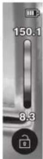
To determine the temperature at a specific spot, move the measuring tool so that the crosshair with the temperature indicator (m) is aimed at the desired point or area. With automatic adjustment, the color spectrum of the scale is always distributed linearly (= evenly) across the entire measurement range within the maximum or minimum temperature.
The measuring tool shows all temperature measurements within the measurement range relative to each other. If heat is displayed in blue in the color palette, for example in the color representation, this means that the blue areas have colder measurement values in the current range. However, these areas may still be within the range
in a temperature zone that, under certain circumstances, can lead to injury. Therefore, always pay attention to the temperature displayed on the scale or directly on the crosshair.
Functions
Pay attention to the instructions regarding navigation through the various menus (see "Navigating through the various menus", page 196).

Illumination of the measuring object
The measuring tool is equipped with a work light (4). It is designed to illuminate the work area directly in front of the measuring tool when taking pictures and is used as a constant work light.
To switch the work light on/off, go to the left side panel. Scroll to the menu item <LED on>/<LED off> and confirm your selection. If the work light is switched on, this is displayed in the status bar.
The light automatically switches off after 2 minutes to avoid affecting measurement accuracy.
The automatic switch-off time can be set in the <Tool settings> menu item.
Overlay of thermal and real image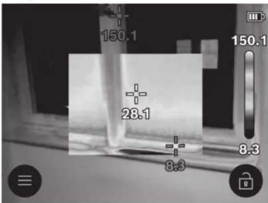
To help you orient yourself (= spatial location of the displayed thermal image), the visual real image can also be displayed if the temperature ranges are balanced.
Note: The overlay of real and thermal images occurs at a distance of exactly 1 m. If the distances to the measuring objects differ, the real and thermal images shift relative to each other. This shift can be compensated for using special Bosch apps. For information on apps and their compatibility, see the
web page describing the measuring tool or at www.bosch-professional.com/thermal.
The measuring tool offers the following options:
- 100% infrared image
Only the thermal image is displayed.

Semi-transparent overlay
A semi-transparent thermal image is overlaid on the real image. This allows for better object recognition. To activate/deactivate this setting, go to the left side panel and scroll to the menu item <Visual image on>/<Visual image off>. Confirm your selection by pressing the multi-function button (17) in the middle.
Picture-in-picture
The displayed thermal image is formed, and the surrounding areas are displayed as the real image. This setting improves the display of the measurement range in the local space. To activate/deactivate this setting, go to the left side panel and scroll to the menu item <Picture in picture on>/<Picture in picture off>. Confirm your selection by pressing the multi-function button (17) in the middle.
Color display setting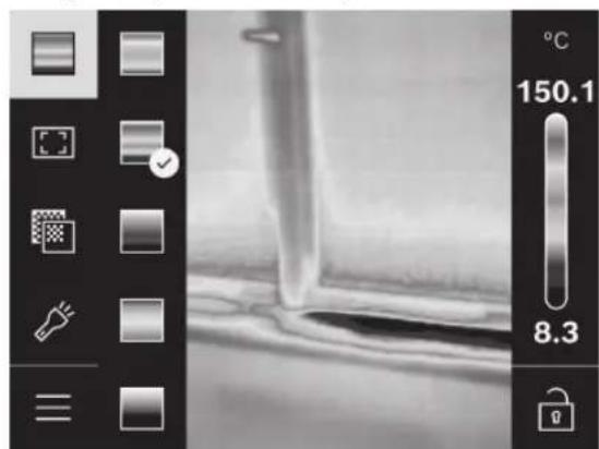
Depending on the measurement situation, different color palettes can facilitate the analysis of thermal images and display objects or conditions more clearly on the screen. This does not affect the measured temperature. Only the representation of temperature values changes.
To change the color palette, go to the side panel and scroll to the menu item 'Color palette'. Confirm your selection by pressing the multi-function button (17) in the middle.

Scale locking
The color distribution on the thermal image is adjusted automatically, but it can be set to a fixed value by pressing the multi-function button (17) to the right, and then in the middle. This allows for comparing thermal images taken under different temperature conditions (e.g., when checking several rooms for 'cold bridges') or hiding the coldest or hottest object on the thermal image, which would otherwise distort the measurements (e.g., a radiator as a hot object when searching for 'cold bridges').
To switch the scale back to automatic mode, go to the right side panel and press the multi-function button (17) in the middle. The temperature now changes dynamically again and adapts to the minimum and maximum measurement values.
Main menu
Go to the left side panel (see 'Navigation through the various menus', Page 196). To access the main menu, press the multi-function button (17) in the middle.
- <Gallery> In this menu item, you can delete saved images individually or all at once.
- <Measurement parameters>
• <Emissivity> (a)
For some of the most common materials, saved emissivity coefficients are available for selection. To make searching easier, the values are grouped in the emissivity coefficient catalog. First, select the appropriate category by going to the <Material Catalog> menu item, and then the corresponding material. If you know the exact emissivity level of your measurement object, you can also set its numerical value in the <User Defined> menu item.
• <Reflected Temperature> (b)
Adjusting this parameter can improve the measurement result, especially for materials with low emissivity (= higher reflectivity). In some conditions (especially indoors), the reflected temperature corresponds to the ambient temperature. If objects with significantly different temperatures near highly reflective objects can affect the measurement, this value should be adjusted. To do this, press the multi-function button (17) on the left or right.
- <Temperature Range>
To ensure high accuracy across the entire measurement range, measurements are performed in two temperature ranges. In <Auto> measurement mode, the instrument automatically selects the appropriate temperature range based on the dis-
tribution of temperature in the thermal image. It evaluates the number of measurement values exceeding a certain temperature threshold. If very small hot objects need to be measured, it is possible to select a low temperature range that is not suitable for high temperatures. This can be recognized by the preceding "\~" symbol on the temperature indicator. In this case, switch to the measurement function
<100 °C ... 450 °C> or <-20 °C ... 100 °C>, where the color distribution corresponds to the set temperature range. The setting is marked on the scale with an up or down arrow.
- <Display Settings>
• <Center Point> (m): <ON>/<OFF> The point is displayed in the middle of the thermal image and shows the measured temperature value at that location (point). • <Hot Spot> (n): <ON>/<OFF> The hottest point (= measurement pixel) is marked with a red crosshair on the thermal image. This simplifies finding critical points (e.g., terminals with loose contacts in a distribution cabinet). - <Cold Spot> (I): <ON>/<OFF> The coldest point (= measurement pixel) is marked with a red crosshair on the thermal image. This simplifies finding critical points (e.g., places of heat loss on windows). • <Temperature Scale> (i): <ON>/<OFF> • <Average Temperature> (c): <ON>/<OFF> The average temperature (c) is displayed in the upper left corner of the thermal image (average temperature of all measurement values on the thermal image). This can facilitate the process of determining the reflected temperature.
- <Instrument Settings>
- <Display Brightness>
Here you can adjust the brightness of the display backlight.
• <LED Off after ...>
In this menu item, you can set the time interval after which the work light will automatically turn off if no button is pressed.
• <Tool off after ...>
In this menu item, you can select the time interval after which the measuring tool will automatically switch off if no buttons are pressed. You can also disable the automatic switch-off by selecting the <Never> setting.
• <Date/Time>
In this submenu, in addition to setting the time and date, you can also change their formats.
- <Language>
In this menu item, you can select the interface language.
200 | English
- <Factory settings>
By navigating to this menu item, you can reset the measuring tool to factory settings and permanently delete all data. The process may take a few minutes. Press the multifunction button (17) on the right to delete all files, or the multifunction button (17) on the left to cancel the process.
- <Information>
In this menu item, you can call up information about the measuring tool. It shows the serial number of the measuring tool and the version of the installed software. You can also find additional information about the measuring tool and software updates here.
You can also press the measurement button (6) to exit any menu level and return to the standard screen.
Updating the measuring tool software
If necessary, you can update the measuring tool software via the USB Type-C® interface. More information is available at: www.bosch-professional.com/thermal-update.
Documenting measurement results
Saving measurement results
Immediately after switching on, the measuring tool starts measuring and continues until it is switched off.
To save an image, point the camera at the desired measuring object and press the "Measure" button (6). The image is saved in the internal memory of the measuring tool. The measurement is frozen and continues to be displayed on the screen. This allows you to examine the image closely and make subsequent adjustments (e.g., to the color palette). If you do not want to save the image, start the measuring mode again by pressing the measure button (6). If you want to save the image in the internal memory of the measuring tool, press the multifunction button (17) in the middle.
Recalling saved images
To recall saved thermal images, proceed as follows:
– Immediately after saving, press the multifunction button (17) in the middle again. A preview image of the last saved snapshot appears on the display. – Alternatively, you can access the saved snapshots via the <Gallery> menu item. – To switch between saved thermal images, press the multifunction button (17) to the right or left.
In addition to the thermal image, a visual image is also saved. To access it, press the multifunction button (17) up or down.
After 5 seconds, the measuring tool switches to full-screen mode. In full-screen mode, the title bar is hidden, so you can view the entire thermal image in detail.
You can switch display modes by pressing the multifunction button (17) up and down.
Deleting saved images
To delete individual or all thermal images, press the multifunction button (17) in the middle. A submenu opens.
– Here you can choose whether to delete only this image or all at once. Confirm your selection by pressing the multifunction button (17) in the middle. When selecting <Delete all images>, you can choose between <Delete all> and <Cancel>. Confirm your selection by pressing the multifunction button (17) in the middle. – In this submenu, you can also view information about the emission coefficient and reflected temperature.
Image data fragments remain in memory and can be restored. To delete permanently, select <Tool settings> in the main menu →
<Factory settings>.
Data transfer
Data transfer via USB interface
Open the cover (11) of the USB Type-C® port. Connect the measuring tool to the computer via the USB Type-C® port (12) using the supplied USB Type-C® cable (16).
Switch on the measuring tool using the on/off switch (18).
Start File Explorer on your computer and select the drive GTC_450. The saved files can be copied from the internal memory of the measuring tool and moved to your computer or deleted.
Once you have completed the necessary actions, disconnect the (external) drive from the computer in the usual way, and then switch off the measuring tool again using the on/off switch (18).
Caution: Always perform a "safe removal" of the external drive from the computer system, otherwise the internal memory of the measuring tool may be damaged.
Disconnect the USB Type-C® cable and close the cover (11).
Always keep the USB interface cover closed to prevent dust or water splashes from entering the housing.
Note: Connect the measuring tool via USB only to a computer. Connecting to other devices may damage the measuring tool.
Note: The USB Type-C® interface is used exclusively for data transfer. It cannot be used to charge batteries or rechargeable batteries.
Post-processing of thermal images
The saved thermal images can be edited using special Bosch applications. Infor-
mation about the applications and their compatibility can be found on the product page of the measuring tool or at www.bosch-professional.com/thermal.
Malfunction – Causes and corrective action
In the event of a malfunction, the measuring tool restarts and can be used again. Otherwise, the overview below will help you take the correct action if error messages continue to appear.
Malfunction Cause Remedy
| Измерительный инструментне включается. | Аккумулятор/элементы питания разряжены | Зарядите аккумулятор или замените элементы питания. | |
 | Неисправность аккумулятора/элементов питания | Замените аккумулятор или элементы питания. | |
 | Аккумулятор/элементы питания слишком горячие или слишком холодные | Дайте аккумулятору термически стабилизироваться или замените аккумулятор/элементы питания. | |
 | Измерительный инструмент перегрелся или слишком холодный | Дайте измерительному инструменту термически стабилизироваться. | |
| [x7w8] | USB-соединение или USB-кабель неисправны | Проверьте, можно ли подключить измерительный инструмент к другому компьютеру. Если нет, сдайте измерительный инструмент на ремонт в авторизованный сервисный центрBosch. | |
| Измерительный инструментне подключается к компьютеру. | Указание: всегда используйте USB-кабель, входящий в комплект поставки. | ||
| [ЗНУС] | Кнопочный элемент питания разряжен | Замените кнопочный элемент питания (см. „Замена кнопочного элемента питания (см. рис. C)“, Страница 202). Подтвердите замену посредством «ОК», нажав многофункциональную кнопку(17)посередине. | |
Explanation of terms
More detailed information is available at www.bosch-professional.com/thermal.
Infrared radiation
Infrared radiation is electromagnetic radiation emitted by every body at a temperature above 0 Kelvin (-273 °C). The radiation dose depends on the temperature and the emissivity of the body.
Emissivity
The emissivity of an object depends on the material and structure of its surface. It indicates how much infrared radiation the object emits compared to an ideal heat radiator (black body, emissivity € = 1) and therefore has a numerical value in the range from 0 to 1.
Thermal bridge
A thermal bridge is a section on the external wall of a building where, due to structural features, a zone of increased heat loss forms locally.
The presence of thermal bridges can lead to an increased risk of mold formation.
Reflected temperature/reflectivity of objects
Reflected temperature is thermal radiation that does not originate from the object itself. Depending on the structure and material, ambient radiation is reflected from the measured object and thus distorts the actual temperature measurement result.
Distance to the measurement object
The distance between the measurement object and the measuring tool affects the size of the area recorded per pixel. As the distance to the object increases, you can capture larger objects.
202 | Russian
| Расстояние (м) Величина инфракрасного пикселя (мм) | Ширина × высота инфракрасного диапазона (м) |
| 0,30 1,14 ~ 0,29 × 0,22 | |
| 0,55 2,08 ~ 0,53 × 0,40 | |
| 1,00 3,79 ~ 0,97 × 0,73 | |
| 2,00 7,58 ~ 1,94 × 1,46 | |
| 5,00 18,95 ~ 4,85 × 3,64 |
Maintenance and Service
Maintenance and Cleaning
Always store and transport the measuring tool in a suitable container, e.g., the original packaging.
Always keep the measuring tool clean.
A dirty infrared sensor (5) can cause a reduction in measurement accuracy.
When cleaning the measuring tool, ensure that no liquid enters it.
Do not attempt to remove dirt from the infrared sensor (5), camera (3), work light (4), or laser beam outlet (2) with sharp/pointed objects. Do not wipe the infrared sensor and camera (risk of scratching).
Clean especially the surfaces at the laser outlet regularly and ensure that no lint remains.
If you wish to recalibrate your measuring tool, contact an authorized Bosch service center.
Send the measuring tool for repair only in its original packaging.
The measuring tool contains no parts that require user maintenance. Opening the housing may damage the measuring tool.
Replacing the button cell battery (see figure C)
Open the cover (11).
Unscrew the screw (10) securing the button cell. Remove the button cell holder (9) from the measuring tool. Replace the button cell. After installation, tighten the screw (10) of the button cell holder.
Service and application consulting
The service department will answer all your questions regarding repair and maintenance of your product, as well as spare parts. Assembly drawings and spare parts information can be found at: www.bosch-pt.com
Bosch application consultants will be happy to assist you with questions regarding our products and their accessories.
Please always specify the 10-digit product number from the product nameplate in all inquiries and spare parts orders.
For the region: Russia, Belarus, Kazakhstan
Warranty service and repair of power tools, in compliance with the manufacturer's requirements and standards, are carried out in all countries only at official or authorized 'Robert Bosch' service centers. WARNING! Use of counterfeit products is dangerous in operation and may cause harm to your health. Manufacture and distribution of counterfeit products is prosecuted by law in administrative and criminal proceedings.
Russia
Organization authorized by the manufacturer:
LLC 'Robert Bosch', Vashutinskoye Shosse, vl. 24
141400, Khimki, Moscow Region
Tel.: +7 800 100 8007
E-Mail: info.powertools@ru.bosch.com
www.bosch-pt.ru
Other service addresses can be found at:
www.bosch-pt.com/serviceaddresses
Transport
The enclosed lithium-ion batteries are subject to the requirements for the transport of dangerous goods. The batteries can be transported by the user himself by road without the need to comply with additional regulations.
When sending by third parties (e.g., by air or freight forwarder), special packaging and labeling requirements must be observed. In this case, the involvement of a dangerous goods expert is necessary when preparing the shipment.
Send the battery only if the housing is undamaged. Seal the open contacts and pack the battery so that it does not move around in the packaging. Please also observe any additional national regulations.
Disposal

The measuring tool, battery/rechargeable battery, accessories, and packaging must be disposed of in an environmentally friendly manner.
Do not dispose of batteries/rechargeable batteries in household waste!
Only for EU member states:
Used measuring tools, as well as defective or exhausted batteries/rechargeable batteries, must be disposed of
separately. Use the collection systems provided for this purpose.
Incorrect disposal of waste electrical and electronic equipment can have harmful effects on the environment and human health due to the possible presence of hazardous substances.
Batteries/rechargeable batteries:
Lithium-ion:
Please observe the instructions in the "Transport" section (see "Transport", page 202).
Safety Instructions

Read all instructions and follow them to work with the measuring tool safely and reliably. Using the measuring tool
without following these instructions may damage the integrated protective mechanisms. Never make warning labels on the measuring tool unrecognizable. KEEP THESE INSTRUCTIONS SAFE AND PASS THEM ON WHEN TRANSFERRING THE MEASURING TOOL.
Caution – using servicing and adjustment equipment other than that specified in these instructions, or using permitted equipment in an unauthorized manner, may result in hazardous radiation exposure. ▶ The measuring tool is supplied with a laser radiation warning label (it is marked on the illustration of the measuring tool on the page with the figure). If the text of the laser radiation warning label is not in the language of your country, before first commissioning, cover it with the sticker in the language of your country that is included in the delivery.

Do not point the laser beam at people or animals, and do not look into the direct or reflected laser beam yourself. It can blind other people, cause accidents, or damage eyes.
If the laser beam hits your eye, deliberately close your eyes and immediately turn away from the beam. Do not change anything in the laser device. ▶ Do not use laser goggles (accessory) as protective goggles. Laser goggles
provide better recognition of the laser beam, but they do not protect against laser radiation.
▶ Do not use the laser glasses (accessory) as sunglasses or wear them while driving. Laser glasses do not provide full UV protection and impair color recognition. Have your measuring tool serviced only by qualified specialists and only with original spare parts. Only then will your measuring tool remain safe. ▶ Do not allow children to use the laser measuring tool without supervision. Children could unintentionally blind themselves or others. Do not operate the measuring tool in environments where there is a risk of explosion due to the presence of flammable liquids, gases, or dust. Sparks may be generated in the measuring tool, which could ignite dust or fumes. ▶ Do not make any modifications to the battery or open it. There is a risk of short circuiting. ▶ If the battery is damaged or used improperly, vapor may be emitted. The battery may catch fire or explode. Provide fresh air and, if you experience any symptoms, consult a doctor. The vapor may irritate the respiratory tract. ▶ If used improperly, liquid may leak from the battery. Avoid contact with it. In case of accidental contact, rinse the affected area with water. If the liquid gets into your eyes, also seek medical attention. Battery fluid may cause skin irritation or burns. Sharp objects such as nails or screwdrivers, or applying external force, can damage the battery. This may cause an internal short circuit, fire, smoke, explosion, or overheating of the battery. Do not store a battery that you are not using near paper clips, keys, nails, screws, or other small metal objects that could bridge the contacts. A short circuit between the battery contacts may cause burns or fire. ▶ Use the battery only in products from the manufacturer. Only then will the battery be protected against dangerous overload. Charge batteries only in chargers recommended by the manufacturer. Using a charger that is not intended for the battery may cause a fire.
Protect the battery from heat, for example from direct sunlight, fire, dirt, water, and moisture. There is a risk of explosion and short circuit.

WARNING

Keep button cells out of the reach of children. Button cells are dangerous.
Miniature batteries must not be swallowed or inserted into other natural body orifices. If you suspect that a miniature battery has been swallowed or inserted through other natural orifices, seek medical attention immediately. Swallowing a miniature battery can cause severe internal burns and death within 2 hours. ▶ Replace miniature batteries properly. There is a risk of explosion. ▶ Use only the button cell batteries specified in these operating instructions. Do not use any other miniature batteries or other power sources. Do not attempt to recharge a miniature battery and do not short-circuit a miniature battery. The miniature battery may leak, explode, catch fire, and cause injury. Remove and dispose of discharged miniature batteries in accordance with regulations. Discharged miniature batteries may leak and damage the product or cause injury. Do not overheat the miniature battery or throw it into fire. The miniature battery may leak, explode, catch fire, and cause injury. Do not damage or disassemble the miniature battery. The miniature battery may leak, explode, catch fire, and cause injury. Do not allow the miniature battery to come into contact with water. Released lithium may react with hydrogen in water, causing fire, explosion, or injury. If the battery holder does not close properly and securely, stop using the measuring tool, remove the battery, and have it repaired. ▶ A large temperature difference in the thermal image may mean that even high
temperatures are displayed in a color associated with low temperatures. Contact with such a surface can cause burns.
Accurate temperature measurement is only possible when the set emissivity and the emissivity of the object match. Objects may appear hotter or colder, which can lead to danger when touched. ▶ Do not point the measuring tool directly at the sun or a powerful CO2 laser. This can damage the detector. Protect the measuring tool, especially the camera area and the infrared lens, from moisture, snow, dust, and dirt. The receiving lens may become covered with condensation or dirt and distort measurement results. Incorrect tool settings as well as atmospheric influences can lead to incorrect measurements. Objects may appear hotter or colder, which can lead to danger when touched.
Product Description and Services
Please be careful and follow the illustrations at the beginning of the operating instructions.
Intended Use
This thermal imager is intended for non-contact measurement of surface temperature.
The displayed thermal image shows the temperature distribution in the field of view of the thermal imager and thus allows temperature variations to be displayed in different colors.
When used correctly, surfaces and objects can be examined contactlessly for temperature differences or deviations from the norm, in order to see details and/or possible weak points, including:
– thermal insulation and insulation (e.g., finding thermal bridges), – active heating and hot water systems (e.g., underfloor heating) in floors and walls, – overheated electrical components (e.g., fuses or terminals), – defective or damaged machine parts (e.g., overheating due to faulty ball bearings).
The measuring tool is not suitable for measuring the temperature of gases.
The measuring tool must not be used for medical purposes.
For information on veterinary applications, see www.bosch-professional.com/thermal. The measuring tool is suitable for indoor and outdoor use.
This is a consumer laser product in accordance with EN 50689.
The illumination of the measuring tool is intended for direct lighting of the working area of the measuring tool for photography and does not serve as a permanent work light.
The laser point must not be used as a pointer. It is only used for marking on the measurement surface.
Depicted components
The numbering of the depicted components refers to the illustration of the measuring tool on the graphics page.
(1) Protective cap (2) Laser beam outlet (3) Visual camera (4) Work light (5) Infrared sensor (6) Pause/start measurement button (7) Battery compartment (8) Warning label for laser operation (9) Holder for miniature power cell (10) Screw for miniature power cell holder (11) Housing of USB socket and miniature power cell holder (12) USB Type-C®a) socket (13) Laser button (14) Battery/ battery adapter unlock button (15) Rechargeable battery b) (16) USB Type-C®b) cable
(17) Multi-function button (18) On/off/back button (19) Display (20) Serial number (21) Battery adapter cover (22) Batteries b) (23) Battery adapter cover a) USB Type-C® and USB-C® are trademarks of USB Implementers Forum. b) The accessories shown or described are not included in the standard delivery.
Indication elements
(a) Emissivity indication (b) Reflected temperature indication (c) Average temperature indication (d) Memory full symbol (e) Work light symbol (f) Laser symbol (g) Battery charge indicator (h) Maximum surface temperature indicator in the measurement range (i) Scale (j) Minimum surface temperature indicator in the measurement range (k) Temperature scale lock symbol (1) Cold spot indicator (as an example) (m) Crosshair with temperature indication (n) Hot spot indicator (as an example) (o) Menu symbol
Technical specifications
| Тепловізор GTC 12V-450-13 | |
| Товарний номер | 3 601 K83 900 |
| Роздільна здатність інфрачервоного датчика 256 × 192 пікселів | |
| Термочутливість A) | ≤ 50 мк |
| Спектральний діапазон 8–14 мкм | |
| Поле зору (FOV) A) | 55,6° × 42° |
| Просторова роздільна здатність (IFOV) 3,79 мрад | |
| Фокусна відстань A) | ≥ 0,5 м |
| Фокус фіксований | |
| Частота повторення імпульсів теплового зображення ≤ 9 Гц | |
| Діапазон вимірювання температури поверхні A) | -20 ... +450° C |
| Точність вимірювання температури поверхні A(B/C) | |
| >0°C ... ≤ +100°CD) | ± 2° C |
| >+100°CE) | ± 2% |
| Роздільна здатність температури 0,1° C | |
| Тип дисплея TFT | |
Thermal imager GTC 12V-450-13
| Розмір дисплея 2,8" | |
| Роздільна здатність дисплея 480 × 360 пікселів | |
| Роздільна здатність інтегрованої візуальної камери 2 Мпікс. (640 × 480 пікс.) | |
| Формат зображення .jpg | |
| Елементи, що зберігаються за одну операцію 1 × теплове зображення (знімок екрана)1 × візуальне реальне зображення, вкл. значення температури (метадані) | |
| Макс. кількість зображень у внутрішній пам'яті 500 | |
| Макс. висота використання над реперною висотою 2000 м | |
| Ступінь забрудненості відповідно до IEC 61010-1 2 | F) |
| Відносна вологість повітря макс. A) | 90 % |
| Клас лазера 2 | |
| Тип лазера < 1 мВт, 645–660 нм | |
| Розбіжність лазерного променя 1,5 мрад (повний кут) | |
| Живлення | |
| – Акумуляторна батарея (літій-іонна) 12 В | |
| – Лужно-марганцеві батарейки (з перехідником для батарейок) | 4 × 1,5 В LR6 (AA) |
| – Акумулятори (NiMH, з перехідником для батарейок) 4 × 1,2 В HR6 (AA) | |
| Робочий ресурсG) | |
| – Акумуляторна батарея (літій-іонна) HII | 8 год |
| – Батарейки (лужно-марганцеві) 4 год | |
| Системний час при надходженні електроживлення | CR1225 (літієва батарея 3 В) |
| USB-стандарт | 2.0 |
| Інтерфейс USB | USB Type-C® |
| BагаJ) | 0,354 кг |
| Розміри (довжина × ширина × висота)K) | 89 × 79 × 209 мм |
| Ступінь захисту (крім акумулятора/батарейок, у вертикальному положенні) | IP54 |
| Рекомендована температура навколишнього середовища при заряджанні | 0 °C ... +35 °C |
| Допустима температура навколишнього середовища | |
| – в роботі | -10 °C ... +50 °C |
| – при зберіганні з акумулятором | -20 °C ... +50 °C |
| – при зберіганні без акумулятора | -20 °C ... +70 °C |
| Рекомендовані акумуляторні батареї | GBA 12V... |
Thermal imager GTC 12V-450-13
Recommended chargers GAL 12...
GAX 18...
A) according to VDI 5585 standard (average value)
B) At an ambient temperature of 20–23 °C and with an emissivity ≥ 0.95, measurement distance: 1 m, operating time: > 5 min, aperture 150 mm, with work light and laser switched off
C) plus application-dependent error (e.g., reflections, distance, ambient temperature)
D) Applies to the center point; for all other pixels, add ± 1 °C
E) Applies to the center point; for all other pixels, add ± 1 %
F) Usually only non-conductive contamination is present. However, temporary conductivity due to condensation may occur.
G) With work light switched off and medium display brightness
H) depending on the battery used
I) at an ambient temperature of 20-30 °C
J) Weight without battery/battery adapter/batteries
K) 3 GBA 12V 2.0Ah or battery adapter
The measuring tool can be clearly identified by the serial number (20) on the rating plate.
Power supply for the measuring tool
The measuring tool can be operated with a Bosch lithium-ion battery, standard batteries, or standard nickel-metal hydride rechargeable batteries.
Operation with the battery (see figure A)
▶ Use only the chargers listed in the technical data. Only these chargers are suitable for the lithium-ion battery used in your measuring tool.
Note: Lithium-ion batteries are supplied partially charged according to international transport regulations. To ensure full battery capacity, fully charge the battery before using the tool for the first time.
To insert the charged battery (15), push it into the battery compartment (7) until it audibly engages.
To remove the battery (15), press the release buttons (14) and pull the battery out of the battery compartment (7). Do not use force.
Operation with batteries (see figure B)
It is recommended to use alkaline-manganese batteries or nickel-metal hydride rechargeable batteries in the measuring tool.
The batteries must be inserted into the battery adapter.
The battery adapter is intended exclusively for use with the Bosch measuring tools for which it is designed, and its use in power tools is prohibited.
To insert the batteries, slide the battery adapter housing (21) into the battery compartment (7). Insert the batteries according to the illustration on the cover (23) into the housing. Push the cover onto the housing until it audibly engages.
To remove the batteries (22), press the release buttons (14) on the cover (23) and remove the cover. Take out the batteries. To remove the inner housing (21), grasp it and pull it out of the measuring tool, gently pressing on the side wall.
Always replace all batteries/rechargeable batteries at the same time. Use only batteries or rechargeable batteries from the same manufacturer and with the same capacity.
Remove the batteries or rechargeable batteries from the measuring tool if you will not be using it for an extended period. During prolonged storage, the batteries or rechargeable batteries may corrode in the measuring tool.
Tips for optimal handling of the rechargeable battery
Protect the rechargeable battery from moisture and water.
Store the rechargeable battery only at temperatures between –20 °C and 50 °C. In particular, do not leave the battery in a car in summer.
Too short a working time after charging indicates that the battery is exhausted and must be replaced.
Observe the disposal instructions.
Operation
- Protect the measuring tool from moisture and direct sunlight.
▶ Do not expose the measuring tool to extreme temperatures or temperature fluctuations. For example, do not leave it
in a car for a long time. If the measuring tool has been subjected to a large temperature change, allow its temperature to stabilize before using it. Extreme temperatures and temperature fluctuations can impair the accuracy of the measuring tool.
Ensure proper acclimatization of the measuring tool. In case of extreme temperature differences, acclimatization may take up to 60 minutes. This can happen, for example, if the measuring tool is stored in a cold car and then used for measurements in a warm room. Avoid strong impacts and dropping the measuring tool. After strong external influences or if the tool behaves unusually, it must be checked by an authorized Bosch service center.
Starting Operation
During First Start-up
During the first start-up of the measuring tool or after resetting it to factory settings, some basic settings must be made. Select the desired values by pressing the multi-function button (17) down, up, left, or right. To confirm your selection, press the multi-function button (17) in the middle. Once you confirm your selection, the next setting appears on the display. The status bar at the top shows the total number of settings and the number of remaining settings.
The following basic settings are available:
- <Language>
- <Date format>
- <Date>
- <Time format>
- <Time>
Switching On/Off
For measuring, open the protective cap (1). During operation, ensure that the infrared sensor is not covered or obscured.
To switch on the measuring tool, press the switch (18). The start-up process is shown on the display (19). After start-up, the measuring tool immediately begins measuring and continues until it is switched off.
Note: In the first few minutes, the measuring tool may calibrate more frequently because the temperature sensor has not yet adapted to the ambient temperature. Sensor calibration allows for accurate measurements. During this time, the temperature indicator may show
\~. This effect is intensified with strong fluctuations in ambient temperature. Therefore, switch on the measuring tool if possible
a few minutes before starting the measurement so that it can stabilize the temperature.
To switch off the measuring tool, press the on/off button (18) for more than 1 second. The measuring tool saves all settings and then switches off. Close the protective cap (1) for safe transport of the measuring tool.
In the main menu, you can choose whether the measuring tool switches off automatically and after what time (see "Main menu", page 211). If the temperature of the battery or the measuring tool goes outside the operating temperature specified in the technical data, the measuring tool switches off automatically after a brief warning (see "Faults – Causes and corrective measures", page 212). Allow the measuring tool to cool down, then switch it on again.
Navigation in the various menus
Navigation in the various menus of the measuring tool:
– To call up the menu lines: press the multi-function button (17) in the middle or on the left. The menu panels appear on the display on the right and left, and the main menu is highlighted. – To scroll in the left menu panel/navigate in the main menu: press the multi-function button (17) up, down, left or right. – To switch to the left or right menu panel: press the multi-function button (17) left or right. – To confirm a selection/switch to a submenu: press the multi-function button (17) in the middle. – To switch from a submenu back to a higher-level menu: press the "Back" button (18).
Preparing for measurement
Setting the emission factor for surface temperature measurement
The emission factor of an object depends on its material and surface structure. It indicates how much infrared thermal radiation the object emits compared with an ideal thermal radiator (black body, emission factor ε = 1), and accordingly takes a value between 0 and 1.
To determine the temperature on the surface in a non-contact manner, the natural infrared radiation from the object at which the tool is aimed is measured. To obtain correct measurement results, you must check the set emission factor before each measurement and, if necessary, adjust it to match the object being measured.
The emission factors preset in the measuring tool are approximate values.
You can select one of the preset emission factors or enter an exact number. Set the required emission factor in the
menu <Measurement parameters> → <Emission factor> (see "Main menu", page 211).
Correct temperature measurement is only possible when the set emission factor and the emission factor of the object match.
The lower the emission coefficient, the stronger the influence of reflected heat on the measurement result. Therefore, if you change the emission coefficient, always adjust the reflected heat value. Set the required emission coefficient in the menu <Measurement parameters> → <Reflected temperature> (see "Main menu", page 211).
If the temperature of the battery or the measuring tool exceeds the operating temperature specified in the technical specifications, the measuring tool automatically switches off after a brief warning. In the case of very different emission coefficients, the displayed temperature differences may differ significantly from the real ones.
If there are several objects in the measuring range made of different materials or with different structures, the displayed temperature values are only correct for objects that correspond to the set emission coefficient. For all other objects (with different emission coefficients), the displayed color differences can be used to indicate the temperature relationship.
Notes on measurement conditions
Surfaces with high reflectivity or shiny surfaces (e.g., glossy tiles or polished metal) can strongly distort or influence the displayed results. If necessary, stick a dark, matte, thermally conductive adhesive tape on the measuring area. Allow the tape to stabilize its temperature on the material surface.
When working on reflective surfaces, ensure that an appropriate measuring angle is used so that reflected heat from other objects does not affect the result. For example, when measuring vertically from the front, the reflection of your body heat can interfere with the measurement. On a flat surface, the contours and temperature of your body (reflected value) may be displayed, which do not correspond to the actual temperature of the measured surface (emitted value or real surface value). Measuring through transparent materials (e.g., glass or transparent plastics) is fundamentally impossible.
The better and more stable the measurement conditions, the more accurate and reliable the measurement results. In this context, not only strong temperature fluctuations in the ambient conditions but also strong temperature fluctuations of the measured object affect the accuracy of the measurement results.
Temperature measurement in the infrared spectrum can be negatively affected by smoke, steam/high humidity, or dusty air.
Tips for improving measurement accuracy:
– Get as close as possible to the measuring object to minimize interference between you and the measuring surface. – Before starting the measurement, ventilate the room, especially if the air is polluted or heavily laden with steam. After ventilation, wait a while so that the room temperature stabilizes and returns to its normal level.
Marking the measuring spot
Do not point the laser beam at people or animals and do not look into the laser beam, even from a distance.
The measuring tool is equipped with a laser for marking the measurement location.
Press and hold the laser button (13). The laser symbol (f) appears in the status bar, and a red circle (m) appears around the crosshair. The laser and crosshair overlap exactly at a distance of 1 m. When the laser button (13) is released, the laser turns off.
Order of temperature values on the scale
On the right side of the display, a scale (i) is shown. The values of the upper and lower limits are based on the maximum (h) and minimum temperature (j) values obtained in the thermal image. The scale evaluates 99.99% of the total number of pixels. The color spectrum of temperature values is distributed evenly (linearly) across the image.
Using different colors, you can set the temperature within these two limit values. For example, the middle color spectrum of the scale corresponds to a temperature that lies exactly between the maximum and minimum values.
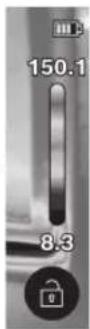
To determine the temperature at a specific area, move the measuring tool so that the crosshair with the temperature indicator (m) is aimed at the desired point or area. With automatic adjustment, the color spectrum of the scale is always distributed linearly (= evenly) across the entire measurement range within the maximum or minimum temperature.
The measuring tool displays all temperature measurements in the measurement range relative to each other. If heat is shown in blue in the color spectrum, for example in the color palette, this means that the blue areas have colder measurement values in the current range. However, these areas may still be within a temperature range that, under certain circumstances, could lead to injury. Therefore, always pay attention to the temperature displayed on the scale or directly at the crosshair.
Functions
Pay attention to the information about navigation in the various menus (see "Navigation in the various menus", page 208)

Illumination of the measurement object
The measuring tool is equipped with a work light (4). It is intended for direct illumination of the working area of the measuring tool for photography and does not serve as a permanent work light.
To turn the work light on/off, call up the left side panel. Scroll to the menu item <LED on>/<LED off> and confirm your selection. When the work light is on, this is shown in the status bar.
The light automatically turns off after 2 minutes to avoid affecting measurement accuracy.
You can adjust the automatic shut-off time in the menu under <Tool settings>.
Overlay of thermal and real image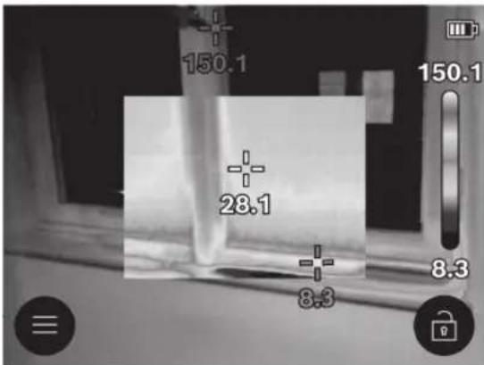
To help you better orient yourself (= spatial location of the displayed thermal image), the visual real image can also be displayed if the temperature ranges are balanced.
Note: The overlay of the real and thermal images is accurate at a distance of 1 m. If the distances to the objects being measured differ, the real and thermal images will be offset relative to each other. This offset is compensated for using special Bosch apps. Information about the apps and their compatibility can be found on the product page of the measuring tool or at www.bosch-professional.com/thermal.
The measuring tool has the following options:
- 100% infrared image
Only the thermal image is displayed.

Overlay
The displayed thermal image is transparently overlaid on the real image. This allows objects to be recognized more easily.
To activate/deactivate this setting, open the left side panel and scroll to the menu item
<Image on>/<Image off>. Confirm your selection by pressing the multifunction button (17) in the middle.
Picture-in-picture
The displayed thermal image is cropped, and the surrounding areas are shown as the real image. This setting improves the local distribution of the measurement range.
To activate/deactivate this setting, open the left side panel and scroll to the menu item <Picture-in-picture on>/<Picture-in-picture off>. Confirm your selection by pressing the multifunction button (17) in the middle.
Color display settings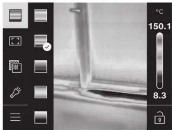
Depending on the measurement situation, different color palettes can make it easier to analyze thermal images and display objects or conditions more clearly on the screen. This does not affect the measured temperature. Only the representation of the temperature values changes.
To change the color palette, open the side panel and scroll to the menu item "Color palette".
Confirm your selection by pressing the multifunction button (17) in the middle.

Scale locking
The color distribution on the thermal image is adjusted automatically, but it can be locked by pressing the multifunction button (17) to the right, then in the middle. This allows you to compare thermal images taken under different temperature conditions (e.g., when checking several rooms for thermal bridges) or to hide the coldest or hottest object on the thermal image, which would otherwise distort the measurements.
(e.g., a radiator as a hot object when searching for thermal bridges).
To switch the scale back to automatic mode, call up the right side panel and press
the multifunction button (17) in the middle. The temperature now changes dynamically again and adapts to the minimum and maximum measurement values.
Main menu
Call up the left side panel (see "Navigating through the various menus", page 208). To open the main menu, press the multifunction button (17) in the middle.
- <Gallery> In this menu item, you can delete saved images individually or all at once.
- <Measurement parameters>
• <Emissivity> (a)
For some of the most common materials, saved emissivity values are available for selection. To make it easier to find the value, the values are divided into groups in the emissivity catalog.
First select the appropriate category by going to the <Material catalog> menu item, then select the appropriate material. If you know the exact emissivity level of your measurement object, you can also enter its numerical value in the <User-defined> menu item.
user-defined>.
• <Reflected temperature> (b)
Adjusting this parameter can improve the measurement result, especially for materials with low emissivity (= higher reflectivity). In some conditions (especially indoors), the reflected temperature corresponds to the ambient temperature. If objects with very different temperatures are near objects with high reflectivity and can affect the measurement, this value needs to be adjusted. To do this, press the multifunction button (17) to the left or right.
- <Temperature range>
To ensure high accuracy across the entire measurement range, measurements are performed in 2 temperature ranges. In the measurement function
<Automatic> the measuring tool automatically selects the appropriate temperature range depending on the temperature distribution in the thermal image. It evaluates how many measured values are above a certain temperature threshold. If very small but hot objects need to be measured, a lower temperature range unsuitable for high temperatures may be selected. This can be recognized by the \~ symbol in front of the temperature indicator.
In such a case, switch to the measurement function <100 °C ... 450 °C> or <-20 °C ...
100 °C>, in which the color distribution corresponds to the set temperature range.
The setting is indicated on the scale by an arrow pointing up or down.
- <Display settings>
• <Center point> (m): <ON>/<OFF>
The point is displayed in the center of the thermal image and shows the temperature value at that location.
• <Hot spot> (n): <ON>/<OFF>
The hottest point (= measurement pixel) is marked with a red crosshair on the thermal image. This simplifies the search for critical points (e.g., terminals with loose contacts in a distribution cabinet).
- <Cold spot> (I): <ON>/<OFF>
The coldest point (= measurement pixel) is marked with a blue crosshair on the thermal image. This simplifies the search for critical points (e.g., air leaks in a window).
- <Temperature scale> (i): <ON>/<OFF>
- <Avg. temp.> (s): <ON>/<OFF>
The average temperature (s) is displayed in the upper left corner of the thermal image (the average temperature of all measurement values on the thermal image). This can facilitate the process of determining the reflected temperature.
- <Tool settings>
• <Screen brightness>
In this menu item, you can adjust the brightness of the display backlight.
• <LED off after ...>
In this menu item, you can select the time interval for automatically switching off the work light if no button is pressed.
• <Tool off after ...>
In this menu item, you can select the time interval after which the measuring tool automatically switches off if no buttons are pressed. You can also deactivate the automatic switch-off by selecting the <Never> setting.
• <Date and time>
In this submenu, you can not only set the time and date, but also change their display formats.
- <Language>
In this menu item, you can select the language in which information is displayed on the screen.
- <Factory settings>
By going to this menu item, you can reset the measuring tool settings to factory defaults and permanently delete all data. The process may take a few minutes. Press the right function button (17) to delete all files or the left function button (17) to cancel.
- <Information>
In this menu item you can call up information about the measuring tool. There you will find the serial number of the measuring tool and the version
212 | Ukrainian
of the installed software. You can also find additional information about the measuring tool and about software updates.
You can also press the measurement button (6) to exit any menu level and return to the standard screen.
Updating the measuring tool software
If necessary, you can update the measuring tool software via the USB Type-C® interface. For more information, see: www.bosch-professional.com/thermal-update.
Documenting measurement results
Saving measurement results
Immediately after switching on, the measuring tool starts measuring immediately and continues until it is switched off.
To save an image, point the camera at the desired measurement object and press the "Measurement" button (6). The image is saved in the internal memory of the measuring tool. The measurement is frozen and continues to be displayed on the screen. This allows you to carefully inspect the image and make subsequent adjustments (e.g., to the color palette). If you do not want to save the image, start the measurement mode again by pressing the measurement button (6). If you want to save the image in the internal memory of the measuring tool, press the multifunction button (17) in the middle.
Calling up saved images
To call up saved thermal images, proceed as follows:
– Immediately after saving, press the multifunction button (17) in the middle again. The preview image of the last saved photo will appear on the display. – Alternatively, you can call up saved photos using the <Gallery> menu item. – To switch between saved thermal images, press the multifunction button (17) to the right or left.
In addition to the thermal image, a visual image is also saved. To call it up, press the multifunction button (17) at the top or bottom.
After 5 seconds, the measuring tool will switch to full-screen mode. In full-screen mode, the title bar display disappears, so you can view all details of the thermal image.
You can switch viewing modes by pressing the multi-function button (17) at the top and bottom.
Deleting saved images
To delete individual or all thermal images, press the multi-function button (17) in the middle. A submenu will open.
– Here you can choose which images to delete — only this one or all images. Confirm your selection by pressing the multi-function button (17) in the middle. If you select <Delete all images>, you can choose between <Delete all> and <Cancel>. Confirm your selection by pressing the multi-function button (17) in the middle.
– In this submenu, you can also view information about the emission coefficient and reflection temperature.
Image data fragments remain in memory and can be recovered. To delete them permanently, select <Tool settings> → <Factory settings> in the main menu.
Data transfer
Data transfer via USB interface
Open the cover (11) of the USB Type-C® port. Connect the measuring tool to the computer via the USB Type-C® port (12) using the USB Type-C® cable (16) from the set.
Switch on the measuring tool using the switch (18).
Start the file manager on your computer and select the drive GTC_450. The saved files can be copied from the internal memory of the measuring tool and moved to your computer or deleted.
Once you have completed the necessary actions, disconnect the external drive from the computer in the usual way, and then switch off the measuring tool again using the switch (18).
Caution: always perform a 'safe removal' of the external drive from the computer, otherwise the internal memory of the measuring tool may be damaged. Remove the USB Type-C® cable and close the cover (11). Always keep the USB interface cover closed to prevent dust or water splashes from entering the housing.
Note: connect the measuring tool via USB only to a computer. When connecting to other devices, the measuring tool may be damaged.
Note: The USB Type-C® interface is used exclusively for data transfer. It cannot be used to charge batteries or accumulators.
Additional processing of thermal images
Saved IR images can be processed using special Bosch software. Information on applications and their compatibility can be found on the product page of the measuring tool or at www.bosch-professional.com/thermal.
Malfunctions – Causes and remedies
In the event of a malfunction, the measuring tool restarts and can be used again. The following overview will help you if error messages appear repeatedly.
Malfunction Cause Remedy
| Вимірювальний інструментне вмикається. | Акумулятор/батарейки розряджені | Зарядіть чи замініть акумуляторні батареї або батарейки. | |
 | Помилка акумулятора/батарейок | Замініть акумуляторні батареї або батарейки. | |
| Акумулятор/батарейки надто теплі або надто холодні | Дайте акумулятору нагрітися/охолонути до температури навколишнього середовища або замініть акумулятор чи батарейки. | |
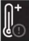 | Вимірювальний інструмент надто теплий або холодний | Дайте вимірювальному інструменту стабілізувати свою температуру. | |
 | USB-з'єднання або USB-кабель несправні | Перевірте, чи можна підключити вимірювальний інструмент до іншого комп'ютера. Якщо ні, передайте вимірювальний інструмент в авторизований сервісний центр Bosch. | |
| Вимірювальний інструментне підключається докомп'ютера. | Вказівка. Завжди використовуйте USB-кабель, щовходить до комплекту поставки. | ||
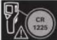 | Мініатюрний елементживлення розряджений | Замініть мініатюрний елемент живлення (див. „Заміна мініатюрного елемента живлення (див. мал. C)“, Сторінка 214). Підтвердьте заміну, вказавши «ОК», для цього натисніть багатофункціональну кнопку (17) посередині. | |
Explanation of terms
For more detailed information, see www.bosch-professional.com/thermal.
Infrared radiation
Infrared radiation is electromagnetic radiation emitted by every body at a temperature above 0 Kelvin (-273 °C). The radiation dose depends on the temperature and the emissivity of the body.
Emissivity
The emissivity of an object depends on its material and surface structure. It indicates how much infrared thermal radiation an object emits compared to an ideal thermal radiator (black body, emissivity ε = 1), and accordingly takes values from 0 to 1.
Thermal bridge
A thermal bridge is an area on the external wall of a building where, due to structural features, a zone of increased heat loss is locally formed. The presence of thermal bridges can lead to an increased risk of mold.
Reflected temperature/reflectivity of objects
Reflected temperature is thermal radiation that does not come from the object itself. Depending on the structure and material, ambient radiation is reflected from the measured object and thus distorts the actual temperature measurement result.
Distance to the measurement object
The distance between the measurement object and the measuring tool affects the size of the area registered per pixel. As the distance to the object increases, you can capture larger objects.
| Відстань (м) Розмірінфрачервоного діапазону (мм) | Ширина × висотаінфрачервоногодіапазону (м) |
| 0,30 1,14 ~ 0,29 × 0,22 | |
| 0,55 2,08 ~ 0,53 × 0,40 | |
| 1,00 3,79 ~ 0,97 × 0,73 | |
| 2,00 7,58 ~ 1,94 × 1,46 | |
| 5,00 18,95 ~ 4,85 × 3,64 |
Maintenance and service
Maintenance and cleaning
Store and transport the measuring tool only in a suitable container, e.g., the original packaging.
Always keep the measuring tool clean. A dirty infrared sensor (5) can cause distorted measurements.
When cleaning the measuring tool, no liquid must penetrate it.
Do not use sharp objects to remove dirt from the infrared sensor (5), camera (3), work light (4), or the laser beam outlet (2). Do not wipe the infrared sensor and camera (risk of scratches).
In particular, regularly clean the surfaces around the laser outlet and ensure that no lint remains.
If you wish to recalibrate your measuring tool, contact an authorized Bosch service center.
Send the measuring tool for repair in its original packaging.
The measuring tool contains no parts that require user maintenance. Opening the housing may damage the measuring tool.
Replacing the miniature battery (see figure C)
Open the cover (11).
Unscrew the screw (10) of the battery holder. Pull the battery holder (9) out of the measuring tool. Replace the battery. After installation, firmly tighten the screw (10) of the battery holder again.
Service and application consulting
The service workshop will answer questions regarding the repair and maintenance of your product. Assembly drawings and information about spare parts are also available at: www.bosch-pt.com
The Bosch team of application consultants will be happy to answer your questions about our products and their accessories.
For all additional questions and spare parts orders, please always specify the 10-digit order number given on the product's nameplate.
Warranty service and repair of power tools are carried out in accordance with the manufacturer's requirements and standards in all countries only at branded or authorized service centers of Robert Bosch. WARNING! Use of counterfeit products is dangerous in operation and may have negative health consequences. The manufacture and distribution of counterfeit products is prosecuted by law in administrative and criminal proceedings.
Ukraine
Bosch Power Tools Service Center, Krainya St. 1
02660 Kyiv 60
Tel.: +380 44 490 2407
Fax: +380 44 512 0591
E-Mail: pt-service@ua.bosch.com
www.bosch-professional.com/ua/uk
The addresses of regional warranty service workshops are indicated in the National Warranty Card.
Further service addresses are listed at:
www.bosch-pt.com/serviceaddresses
Transport
The recommended lithium-ion batteries are subject to the requirements for the transport of dangerous goods. The batteries can be transported by the user by road without the need to comply with additional regulations.
When shipping by third parties (e.g., by air transport or by a freight forwarder), special requirements regarding packaging and labeling must be observed. In this case, a dangerous goods expert must be involved in preparing the shipment.
Only send the battery if its housing is undamaged. Tape off any open contacts and pack the battery so that it cannot move around in the packaging. Please also observe any additional national regulations.
Disposal

Measuring tools, batteries, accessories, and packaging should be sent for environmentally friendly recycling.

Do not dispose of measuring tools and batteries in household waste!
Only for EU countries:
Unusable and defective measuring equipment, as well as used batteries, must be disposed of separately. Use the collection systems provided for this purpose.
In the event of incorrect disposal, waste electrical and electronic equipment can have harmful effects on the environment and human health due to the possible presence of hazardous substances.
Batteries:
Lithium-ion:
Please observe the instructions in the "Transport" section (see "Transport", page 214).
Valid in the territories of the member states of the Eurasian Economic Union (Customs Union)
The manufacturer's operating documents for the product may include this instruction manual, as well as appendices. Information about conformity confirmation is provided in the appendix. Information about the country of manufacture is indicated on the product body and in the appendix. The production date is indicated on the last page of the manual cover and on the product body. Contact information for the importer is indicated on the product packaging.
Product service life
The product's service life is 7 years. After 5 years of storage without use from the production date (the production date is written on the factory plate), it is not recommended to use the product without inspection (service check).
List of errors and failure causes by personnel or user
– If smoke comes directly from the product body, do not use it - Do not use outdoors during precipitation - If water gets inside the body, do not connect the device
Signs of limit state
- Damage to the product body
Type and frequency of maintenance
It is recommended to clean the product after each use.
Storage
- Store in a dry place – keep away from high temperature sources and direct sunlight – protect from sudden temperature fluctuations during storage – if the tool is delivered in a soft bag or plastic case, it is recommended to store it in its protective cover
- For additional information about storage conditions, refer to the document GOST 15150-69 (Condition 1)
Transportation
– During transportation, it is strictly forbidden to drop the product or subject it to any mechanical impact
– During unloading/loading, it is not allowed to use machines that compress the package. - Read the requirements of the transport conditions in GOST 15150-69 (condition 5).
Safety instructions

To work safely and reliably with the measuring tool, you must read and follow all instructions. Failure to use the measuring tool in accordance with these instructions may adversely affect the built-in safety measures of the measuring tool. Do not make the warnings on the measuring tool invisible. KEEP THESE INSTRUCTIONS AND INCLUDE THEM WHEN PASSING THE MEASURING TOOL ON TO OTHERS.
Be careful – if you use equipment or adjustment devices other than those provided here, or if you perform other working methods, this may lead to hazardous radiation exposure. ▶ The measuring tool is delivered with a laser warning label (marked in the illustration of the measuring tool on the graphics page). ▶ If the text on the laser warning label is not in your country's language, stick the label in your country's language over it before the first use.
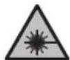
Do not direct the laser beam at people or animals, and do not look directly into the laser beam, whether direct or reflected. This can dazzle people, lead to accidents, or cause eye damage.
▶ If the laser beam hits your eye, close your eyes and turn your head away from the beam.
▶ Do not make any modifications to the laser device.
Do not use laser viewing glasses (accessories) as protective glasses. Laser viewing glasses are used to better see the laser beam, but they do not protect against the laser beam.
▶ Do not use laser viewing glasses (accessories) as sunglasses or while driving. Laser viewing glasses do not provide full protection against ultraviolet rays and reduce color perception.
▶ Have the measuring tool serviced only by a qualified specialist and only with original spare parts. This ensures the safety of the measuring tool.
Do not allow children to use the laser measuring tool without supervision. They could inadvertently dazzle other people's or their own eyes.
Do not use the measuring tool in environments with a risk of explosion where flammable liquids, gases, or dust are present. The measuring tool may produce sparks and ignite dust, causing a fire. ▶ Do not modify or open the battery. There is a risk of short circuit. If the battery is damaged or used improperly, vapors may be emitted. The battery may catch fire or explode. Breathe in fresh air and seek medical help if you have any complaints. Vapors may irritate the respiratory tract. If the battery is used improperly or is damaged, liquid may leak from the battery. Do not touch it. If it accidentally comes into contact with skin, rinse the area with water. If the liquid gets into the eyes, seek medical help. Battery liquid may irritate or burn the skin. ▶ The battery may be damaged by pointed objects such as nails or screwdrivers, or by external impact. This can lead to a short circuit, and the battery may catch fire, emit smoke, explode, or overheat. ▶ Keep unused batteries away from paper clips, coins, keys, nails, screws, and other small metal objects that could bridge the contacts. A short circuit between the battery contacts can lead to burns or fire. ▶ Use this battery only in products from this manufacturer. This protects the battery from dangerous overloading. Charge the battery only with the charging device specified by the manufacturer. A charging device designed for a specific type of battery may pose a fire risk if used with other batteries. Protect the battery from heat, as well as, for example, direct sunlight, fire, dirt, water, and moisture. There is a risk of explosion and short circuit. Ensure that button cells do not fall into the hands of children. Button cells are dangerous. Button cells must never be swallowed or introduced into the body in any other way. If a button cell is swallowed or enters the body in another way, see a doctor immediately. Swallowing a button cell can cause severe internal burns and death within 2 hours.


When replacing the button cell, ensure that the action is performed correctly. There is a risk of explosion. ▶ Only use button cells specified in these operating instructions. Do not use other button cells or other power sources. Do not attempt to charge small batteries, do not attempt to short-circuit them. A small battery may leak, explode, catch fire, and cause injury to persons. Dispose of depleted small batteries properly. Depleted batteries may leak and damage the product or cause injury to persons. Do not overheat the small battery and do not throw it into a fire. A small battery may leak, explode, catch fire, and cause injury to persons. Do not damage the small battery and do not disassemble it. A small battery may leak, explode, catch fire, and cause injury to persons. Do not expose a damaged small battery to water. Escaping lithium may generate hydrogen, which can lead to fire, explosion, or injury to persons. ▶ If the button cell holder no longer closes properly and completely, do not continue to use the measuring tool. Remove the button cell and have the measuring tool repaired. ▶ Large temperature differences in the thermogram may result in high temperatures being associated with low temperatures in the color display. Contact with such surfaces can cause injury. Correct temperature measurements are only possible when the adjusted emissivity matches the emissivity of the object. Objects may be displayed with temperatures that are too high or too low, which can create a hazardous situation during contact actions. ▶ Do not point the measuring tool directly at the sun or at high-power CO₂ lasers. This can damage the detectors. ▶ Protect the measuring tool, especially the camera and infrared lens areas, from moisture, snow, dust, and dirt. The receiver lens may fog up or become contaminated, and measurement results may be incorrect. Incorrect settings of the device and other atmospheric influences can lead to incorrect measurement results. Objects may be displayed with temperatures that are too high or too low, which can create a hazardous situation during contact.
Product and power description
Pay attention to the figures at the front of the operating instructions.
Intended use
The thermal imaging camera is intended for non-contact measurement of surface temperatures.
The displayed thermogram shows the temperature distribution in the field of view of the thermal imaging camera and allows temperature differences to be distinguished by colors.
In this way, when the power tool is used properly, temperature differences or deviations on surfaces and objects can be detected without contact, and building elements and/or potential weak points can be identified, including:
– thermal insulation and insulating materials (e.g., for detecting thermal bridges),
– active heating and cooling pipes in floors and walls (e.g., underfloor heating),
- overheated electrical components (e.g., fuses or terminals).
- Faulty or damaged parts of the device (e.g., strong heating from a defective ball bearing).
The measuring tool is not intended for measuring the temperature of gases.
The measuring tool must not be used for human medical purposes.
For information on use for veterinary purposes, please visit: www.bosch-professional.com/thermal.
The measuring tool is intended for use in indoor and outdoor areas.
This product is a consumer laser product in accordance with EN 50689.
The light of this measuring tool is intended for illuminating the direct working area of the measuring tool for the purpose of taking pictures and is used as a permanent work lamp.
The laser point must not be used as a laser pointer. It is only intended for marking the measuring area.
Displayed components
The numbers of the displayed components refer to the representation of the measuring tool on the page with the figures.
(1) Protective cover (2) Laser beam outlet opening (3) Visual camera (4) Work light (5) Infrared sensor
(6) Pause/start measurement button (7) Battery compartment (8) Laser warning label (9) Button cell holder (10) Screw for button cell holder (11) Cover for USB port and button cell holder (12) USB Type-C® port a) (13) Laser button (14) Release button for battery/battery adapter (15) Battery b) (16) USB Type-C® cable b) (17) Multi-function button (18) On/off button/back button (19) Display (20) Serial number (21) Battery adapter housing (22) Batteries b) (23) Battery adapter cover
a) USB Type-C® and USB-C® are trademarks of USB Implementers Forum.
b) The accessories shown or described are not included in the standard delivery scope.
Indication elements
(a) Emission level indicator (b) Reflected temperature indicator (c) Average temperature indicator (d) "Memory full" symbol (e) Working light symbol (f) Laser symbol (g) Charge level indicator (h) Maximum surface temperature indicator in the measuring range (i) Scale (j) Minimum surface temperature indicator in the measuring range (k) Temperature scale lock symbol (I) Cold spot indicator (example) (m) Cutout with temperature indicator (n) Hot spot indicator (example) (o) Current symbol
Technical data
| Жылуға ден қою камерасы GTC 12V-450-13 | |
| Өнім нөмірі | 3 601 K83 900 |
| Инфрақызыл датчиктің ажыратымдылығы 256 × 192 пкс | |
| Термиялық сезімталдығы A) | ≤ 50 мк |
218|Kazakh
Thermal imaging camera GTC 12V-450-13
| Спектріл аймак 8–14 мкм | |
| Керу өрісі (FOV)A) | 55,6° × 42° |
| Кеңістіктік ажыратымдылық (IFOV) 3,79 мрад | |
| Фокус арақашықтығыA) | ≥0,5 м |
| Фокус тұрақты | |
| Термограмма кескінінің қалпына келу жиілігі ≤ 9 Гц | |
| Беткі температураның өлшеу диапазоныA) | -20 ... +450°C |
| Беткі температураны өлшеу дәлдігіA)(C) | |
| >0°C ... ≤ +100°C D) | ±2°C |
| >+100°C E) | ±2% |
| Температура ажыратымдылығы 0,1°C | |
| Дисплей түрі TFT | |
| Дисплей өлшемі 2,8" | |
| Дисплей ажыратымдылығы 480 × 360 пкс | |
| Интеграцияланған визуалды камераның ажыратымдылығы 2 МП (640 × 480 пкс) | |
| Кескін пішімі .jpg | |
| Әр сақтау процесінде сақталатын элементтер 1 × термограмма (скриншот),1 × визуалды шынайы кескін, соның ішінде температурамәндәрі (метадеректер) | |
| Ішкі сурет жадындағы суреттердің макс. саны 500 | |
| Негізгі биіктіктің үстіндегі макс. пайдалану биіктігі 2000 м | |
| Ластану дәрежесі IEC 61010-1 стандарты бойынша 2 | F) |
| Салыстырмалы ауа ылғалдылығы, макс. A) | 90% |
| Лазер класы 2 | |
| Лазер түрі | <1 мВт, 645–660 нм |
| Лазер сәулесінің айырмашылығы | 1,5 мрад (толық бұрыш) |
| Куатпен жабдықтау | |
| – Аккумулятор (литий-иондық) | 12 В |
| – Батареялар (сілтілі-марганец, батарея адаптері бар) | 4 × 1,5 В LR6 (AA) |
| – Аккумуляторлар (NiMH, батарея адаптері бар) | 4 × 1,2 В HR6 (AA) |
| Жұмыс ұзақтығы(3) | |
| – Аккумулятор (литий-иондық)H)) | 8 сағ |
| – Батареялар (сілтілі-марганец) | 4 сағ |
| Куатпен жабдықтау, жүйелік уақыт | CR1225 (3 В литий батареасы) |
| USB стандарты | 2.0 |
| USB интерфейсі | USB Type-C® |
| СалмағыJ) | 0,354 кг |
| Өлшемдері (ұзындығы × ені × биіктігі)K) | 89 × 79 × 209 мм |
| Қорғаныс дәрежесі (аккумулятор/батареялар шығарылған, тік күйде) | IP54 |
| Зарядтау кезіндегі ұсынылатын қоршаған орта температурасы | 0°C ... +35°C |
| Рұқсат етілген қоршаған орта температуралары | |
| – Жұмыс кезінде | -10°C ... +50°C |
| – Аккумулятормен сақтаған кезде | -20°C ... +50°C |
| – Аккумуляторсыз сақтаған кезде | -20°C ... +70°C |
1609 92A 9ZG | (14.01.2025)
Bosch Power Tools
Thermal imaging camera GTC 12V-450-13
Recommended batteries GBA 12V...
Recommended chargers GAL 12...
GAX 18...
A) According to VDI 5585 standard (average value) B) At ambient temperature 20–23°C and emission level ≥ 0.95, measuring distance: 1 m, operating time > 5 minutes, at 150 mm aperture, with working light and laser off C) Deviation due to application (e.g., reflection, distance, ambient temperature) D) Applies to the center point, additional ±1℃ for all other pixels E) Applies to the center point, additional ±1% for all other pixels F) Only non-conductive dirt occurs, but in some cases conductivity may arise due to melting. G) With working light off and average display brightness H) Depends on the battery used I) At ambient temperature around 20-30°C J) Weight without battery/battery adapter/batteries K) With GBA 12V 2.0Ah battery or battery adapter The serial number (20) on the measuring tool's nameplate helps to identify it unambiguously.
Power supply for the measuring tool
The measuring tool can be operated with a Bosch lithium-ion battery, standard batteries, or standard NiMH batteries.
Operation with battery
(See figure A)
Use only the chargers specified in the technical data. Only these chargers are compatible with the lithium-ion battery inside your measuring tool.
Note: Lithium-ion batteries are shipped partially charged according to international transport regulations. To utilize the full battery capacity, fully charge the battery before first use.
To insert the charged battery (15), push it into the battery compartment (7) until it clicks into place.
To remove the battery (15), press the release buttons (14) and pull the battery out of the battery compartment (7). Do not use force.
Operation with batteries
(see figure B)
It is recommended to use alkaline-manganese batteries or NiMH rechargeable batteries for the measuring tool.
The batteries are inserted into the battery adapter.
The battery adapter is intended only for use with the corresponding Bosch inspection camera and must not be used with power tools.
To insert the batteries, insert the battery adapter case (21) into the battery compartment (7).
Insert the batteries into the cover (23) as shown in the figure. Slide the cover over the case until it clicks into place.
To remove the batteries (22), press the release buttons (14) on the cover (23) and pull off the cover. Remove the batteries. To remove the inner case (21) from the battery compartment, grasp the case and pull it out of the measuring tool while pressing slightly on the side wall.
Always replace all batteries or rechargeable batteries at the same time. Use only batteries or rechargeable batteries from one manufacturer and with the same capacity.
If the measuring tool is not used for a long period, remove the batteries or rechargeable batteries from it. Batteries or rechargeable batteries stored in the measuring tool for a long time may corrode.
Instructions for optimal battery use
Protect the battery from liquids and moisture.
Store the battery only in a temperature range of –20 °C ... 50 °C. Do not leave the battery in the vehicle in summer.
A significant reduction in service life indicates that the battery is old and needs to be replaced.
Follow the instructions for recycling waste.
Operation
▶ Protect the measuring tool from drafts and direct sunlight. ▶ The measuring tool must not be exposed to extreme temperatures or temperature fluctuations. Do not leave it in the vehicle for a long time, for example.
In the event of large temperature fluctuations, allow the measuring tool to acclimate to the correct temperature before use. In the event of extreme temperatures or temperature fluctuations, the accuracy of the measuring tool may decrease.
▶ Ensure proper acclimatization of the measuring tool. In the event of sudden temperature changes, the acclimatization time may take up to 60 minutes. This can occur, for example, when the measuring tool is stored in a cold car and then the measurement is performed in a warm building. ▶ Protect the measuring tool from strong impacts or falls. After strong external influences and if there are malfunctions in its functional capability, have the measuring tool checked at an authorized Bosch service center.
Initial Operation
When switching on for the first time
When switching on the measuring tool for the first time or after resetting to the factory settings, some basic settings must be performed. Use the multi-function button (17) to select the desired values by pressing it on the lower, upper, left, or right side. To confirm the selection, press the multi-function button (17) in the center. After the selection is confirmed, the next setting is shown on the display. The total number and the number of remaining settings are shown in the upper status bar.
The following basic settings are available:
- <date format>
- <time format>
Switching on/off
Open the protective cap (1) for measuring. Make sure that the infrared sensor is not blocked or covered during operation.
To switch on the measuring tool, press the on/off button (18). The start sequence appears on the display (19). After the start sequence, the measuring tool immediately starts measuring and continues continuously until it is switched off.
Note: During the first few minutes, the measuring tool may self-calibrate more frequently because the sensor and ambient temperature are not yet aligned. A fresh calibration of the sensor enables precise measurement. During this time, the temperature indicator may be shown with the ~ symbol. If the ambient temperature fluctuates greatly, this effect may be amplified. Therefore, to stabilize the temperature of the measuring tool, switch it on a few minutes before starting the measurement if possible.
To switch off the measuring tool, press and hold the on/off button (18) for more than 1 second. The measuring tool saves all settings and then switches off. Close the protective cap (1) for safe transport.
In the main menu, you can select whether and when the measuring tool should switch off automatically (see "Main menu", page 223).
If the battery or the measuring tool is outside the operating temperature specified in the technical data, the measuring tool switches off automatically after a brief warning (see "Faults – causes and remedies", page 224). Restore the temperature of the measuring tool and then switch it on again.
Navigating through the various menus
Navigating through the various menus of the measuring tool:
– To call up the menu bars: press the multi-function button (17) in the center or on the left side. The left and right menu bars appear on the display, with the main menu highlighted. – To scroll through the left menu bar / go to the main menu: press the multi-function button (17) at the top, bottom, left, or right. – To switch to the right or left menu bar: press the multi-function button (17) on the left or right side. – To confirm a selection / switch to a submenu: press the multi-function button (17) in the center. – To return from a submenu to a higher-level menu: press the back button (18).
Preparing for measurement
Setting the emission degree for surface temperature measurement
The emission degree of an object depends on the material and structure of the surface. It indicates how much infrared heat radiation the object emits compared to an ideal heat radiator (black body, emission degree ɛ = 1) and accordingly takes a value between 0 and 1.
To determine the surface temperature, the natural infrared heat radiation emitted by the target object is measured without contact. For correct measurement, the emission degree set on the measuring tool must be checked before each measurement and, if necessary, adjusted to the measurement object.
The pre-set emission levels in the measuring tool are approximate values.
You can select one of the pre-set emission levels or enter an exact numerical value.
Adjust the desired emission level via the <Measuring parameters> →
<Emission level> menu (see "Main menu", page 223).
Correct temperature measurements are only possible when the set emission level matches the emission level of the object.
The lower the emission level, the greater the influence of reflected temperature on the measurement result. Therefore, always adjust the reflected temperature when changing the emission level. Adjust the reflected temperature via the <Measuring parameters> →
<Reflected temperature> menu (see "Main menu", page 223).
Temperature differences displayed by the measuring tool can be attributed to different temperatures and/or different emission levels. If emission levels differ significantly, the displayed temperature differences may deviate considerably from actual values. If there are multiple measuring objects made of different materials or with different structures within the measuring range, the displayed temperature values will only be accurate for objects that match the set emission level. For all other objects (with different emission levels), the displayed color differences can be used as an indication of temperature relationships.
Instructions on measuring conditions
Highly reflective or glossy surfaces (e.g., polished tiles or shiny metals) can significantly distort or affect the displayed results. If necessary, apply a brown, matte adhesive tape that conducts heat to the measuring range. Briefly allow the tape to adapt to the surface temperature.
To prevent reflected thermal radiation from other objects from affecting the result, ensure a suitable measuring angle on reflective surfaces. For example, when measuring vertically from the front, the reflection of your own body heat may affect the measurement. On flat surfaces, the contour and temperature of your body may be displayed, which do not correspond to the actual temperature of the measured surface (the emitted or actual value of the surface).
Measurement is not possible on transparent materials (e.g., glass or transparent plastic) due to the working principle.
The better and more stable the measuring conditions, the more accurate and reliable the measurement results. In this regard, not only strong temperature fluctuations in the ambient conditions are relevant, but also strong fluctuations in the temperature of the measured object can affect accuracy.
Smoke, vapor/high air humidity, or dusty air affect the infrared temperature measurement.
Instructions for improving measurement accuracy:
– Get as close as possible to the object being measured to minimize any obstructions between you and the measuring surface.
– Before measuring, ventilate the room, especially if the air is dusty or very humid. After ventilating the room,
allow the temperature to return to its normal level.
Marking the measuring point
Do not point the laser beam at people or animals, and do not look into the laser beam yourself, even from a distance.
The measuring tool is equipped with a laser for marking the measuring point.
Press and hold the laser button (13). The laser indicator (f) will appear on the status panel, and a red cross will be displayed around the measuring spot (m). The laser and the measuring spot overlap precisely at a distance of approximately 1 m. When the laser button (13) is released, the laser turns off.
Assigning temperatures on the scale
A scale (i) is displayed on the right side of the display. The values at the upper and lower edges are based on the maximum temperature (h) or minimum temperature (j) recorded in the thermogram. 99.99% of all pixels are considered for the scale. The assignment of colors to temperature values in the image is done through uniform distribution (linear).
With the help of different colors, temperatures within these two limit values can be assigned. A temperature lying exactly between the maximum and minimum values is assigned, for example, to the middle color range of the scale.
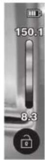
To determine the temperature of a specific area, move the measuring tool so that the measuring spot (m) with the temperature indicator is directed at the desired point or area. In automatic adjustment, the color spectrum of the scale is always linearly (= uniformly) distributed over the entire range of measurements within the maximum or minimum temperature. The measuring tool displays all measured temperatures in the measurement range relative to each other. If, for example, in a range, in the color display, warm colors appear bluish in the color palette, this means that these bluish ranges are relative to the cooler measured values in the current measurement range. However, these ranges may, in some cases, be within a temperature range that can lead to injury. Therefore, always pay attention to the temperatures displayed on the scale or directly at the measuring spot.
Functions
Pay attention to the information on navigating through the various menus (see "Navigating through the various menus", Page 220)

Illuminating the measuring object
The measuring tool is equipped with a work light (4). It is intended for illuminating the immediate work area of the measuring tool for the purpose of taking pictures and can be used as a constant work lamp.
To switch the work light on or off, call up the left-hand side panel. Scroll to the <LED on>/
<LED off> menu item and confirm the selection. When the work light is switched on, this is shown in the status panel.
The light automatically switches off after 2 minutes so as not to affect measurement accuracy.
The automatic switch-off time can be set in the menu under <Tool settings>.
Overlaying the thermogram and the real image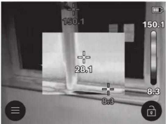
To improve the assignment (= spatial allocation of the displayed thermograms), the visual real image can also be switched on when the temperature ranges are aligned.
Note: The overlay of the real image and the thermogram
is accurate at a distance of approx. 1 m. If the distances to the measurement object differ, a shift will occur between the real image and the thermogram. This shift can be corrected using special Bosch apps.
Information on apps and their compatibility can be found on the product page of the measuring tool or on the website www.bosch-professional.com/thermal.
The measuring tool offers the user the following options:
- 100% infrared image
Only the thermogram is displayed.

- Transparency
The displayed thermogram is placed transparently over the real image. This allows objects to be identified more easily.
To activate/deactivate the adjustment, use the left-hand side
Call up the panel and scroll to the <Visual image on>/<Visual
image off> menu item.
Confirm the selection by pressing the center of the multi-function button (17).
F
-Image within the image
The displayed thermogram is cut out and the surrounding area is shown as a real image. This setting improves the local assignment of the measurement range.
To activate/deactivate the adjustment, call up the left side panel and scroll to the <Image-in-image on>/<Image-in-image
off> menu item. Confirm the selection by pressing the center of the multi-function button (17).
Adjusting the color display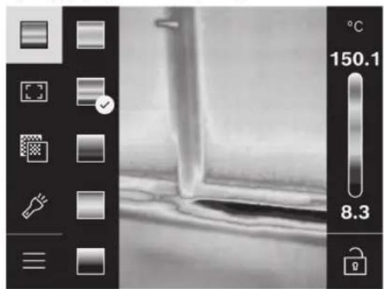
Depending on the measurement situation, different color palettes can facilitate the analysis of the thermogram and display objects or situations more clearly on the screen. The measured temperatures are not affected by this setting. This only changes the display of the temperature values.
To change the color palette, call up the side panel and scroll to the "Color palette" menu item. Confirm the selection by pressing the center of the multi-function button (17).

Locking the scale
The distribution of colors in the thermogram is adjusted automatically, but it can be locked by pressing the multi-function button (17) to the right and then in the center. This allows comparing thermograms recorded under different temperature conditions (e.g., when checking thermal bridges in several rooms) or hiding objects that are too cold or too hot and could distort the thermogram (e.g., a radiator as a hot object when searching for thermal bridges).
To switch the scale back to automatic mode, call up the right side panel and press the center of the multi-function button (17). The temperatures now
react dynamically again and adapt to the measured minimum and maximum values.
Main menu
Open the left side panel (see "Navigating through the various menus", page 220). To go to the main menu, press the multi-function button (17) in the center.
- "Gallery" In this menu item, you can delete saved images one by one or all at once.
- <Size settings>
• <Emissivity> (a)
Several emissivity values are stored in memory for the most frequently measured materials. To make searching easier, the values are grouped in the emissivity catalog. In the <Material catalog> menu item, first select the appropriate category, then the appropriate material. If you know the exact emissivity of the measurement object, you can also set it as a numerical value in the <User-defined> menu item.
• <Reflected temperature> (b)
Adjusting this parameter can improve the measurement result, especially for materials with low emissivity (= higher reflectivity). In some cases (especially indoors), the reflected temperature corresponds to the ambient temperature. If objects with strongly deviating temperatures are near highly reflective objects and can affect the measurement, this value must be adapted. To do this, press the multi-function button (17) on the left or right side.
- <Temperature range>
To ensure high accuracy over the entire measurement range, the measurement is performed in 2 temperature ranges. In the <Automatic> measurement function, the measuring instrument automatically selects the appropriate temperature range based on the temperature distribution in the thermogram. In this process, it is evaluated how many measurement values exceed a certain temperature limit. If very small but hot objects need to be measured, low temperature ranges that are unsuitable for high temperatures may be selected. This can be detected by the preceding \~ symbol in the temperature indication. In this case, switch to the <100 °C ... 450 °C> or <-20 °C ... 100 °C> measurement function, where the color distribution corresponds to the adjusted temperature range. The setting is indicated on the scale by an arrow pointing up or down.
- <Display settings>
• <Center point> (m): <ON>/<OFF> A point is displayed in the center of the thermogram and shows the user the measured temperature value at this location. • <Hot spot> (n): <ON>/<OFF> The hottest point (= measurement pixel) is marked in the thermogram by
a red crosshair. This makes it easier to search for critical areas (e.g., loose contact clamps in a distribution cabinet).
- <Cold spot detector> (I): <ON>/<OFF>
The coldest point (= measurement pixel) is marked in the thermogram by a blue crosshair. This makes it easier to search for critical areas (e.g., leaks in windows).
- <Temperature scale> (i): <ON>/<OFF>
• <Average temperature> (c): <ON>/<OFF>
The average temperature (c) is displayed in the upper left corner of the thermogram (the average temperature of all measured values in the thermogram). This makes it easier for the user to determine the reflected temperature.
- <Instrument settings>
• <Display brightness>
In this menu item, the brightness of the display light can be adjusted.
• <LED off: ...>
In this menu item, you can select the time interval after which the work light automatically turns off when no button is pressed.
• <Instrument off: ...>
In this menu item, you can select the time interval after which the measuring instrument automatically turns off when no button is pressed. Automatic shutdown can also be disabled by selecting the <Never> setting.
• <Date and time>
In this submenu, you can adjust the time and date, as well as change the corresponding format.
•
In this menu item, you can select the language used on the display.
- <Factory settings>
In this menu item, you can reset the measuring tool to the default settings and permanently delete all data. This may take several minutes in some cases. To delete all files, press the multi-function button (17) on the right side, or to stop the action, press the multi-function button (17) on the left side.
- <Information>
In this menu item, you can call up information about the measuring tool. Here you will find the serial number of the measuring tool and the installed software version. In addition, you can find further information about the measuring tool and software updates there.
You can also press the measuring button (6) to exit any menu and return to the standard indicator screen.
224 | Kazakh
Updating the measuring tool software
If necessary, you can update the measuring tool software via the USB Type-C® interface. For more information, see: www.bosch-professional.com/thermal-update.
Documentation of measurement results
Saving measurement results
After switching on, the measuring tool immediately starts measuring and continues continuously until it is switched off. To save an image, point the camera at the desired measuring object and press the measuring button (6). The image is saved in the internal memory of the measuring tool. The measurement is frozen and displayed on the screen. This allows the user to examine the image carefully and make subsequent adjustments (e.g., color palette). If you do not want to save the frozen image, restart the measuring mode by pressing the measuring button (6). If you want to save the image to the internal memory of the measuring tool, press the center of the multi-function button (17).
Recalling saved images
To recall saved thermograms, perform the following steps:
– After saving, press the center of the multi-function button (17) again immediately. The last saved photo preview will appear on the display. – Alternatively, you can recall saved photos in the <Gallery> menu item. – To switch between saved thermograms, press the right or left side of the multi-function button (17).
In addition to the thermogram, a visual image is also saved. To recall it, press the top or bottom of the multi-function button (17).
After 5 seconds, the measuring tool switches to the full image view. In the full image view, the title bar indicator is hidden so that all thermogram data is displayed.
You can switch between views by pressing the multi-function button (17) from the top and bottom.
Deleting saved images
To delete individual or all thermograms, press the center of the multi-function button (17). A submenu will open.
– Here you can choose whether to delete only this image or all images. Make your selection using the multi
function button (17) and confirm by pressing the center.
When <Delete images> is selected, you can choose between <Delete all> and <Cancel>. Confirm your selection by pressing the center of the multi-function button (17).
– In this submenu, you can also view information about the emission level and reflected temperature.
The image data excerpts remain in memory and can be reconstructed. To permanently delete them, select <Tool parameters> → <Default settings> in the main menu.
Data transfer
Transferring data via USB interface
Open the cover of the USB Type-C® port (11). Connect the USB Type-C® port (12) of the measuring tool to your computer using the USB Type-C® cable (16) included in the delivery.
Now turn on the measuring tool using the on/off button (18).
Open the file browser on your computer and select the drive GTC_450. You can copy, move, or delete the saved files from the internal memory of the measuring tool.
After completing the desired action, disconnect the drive from your computer as usual, then turn off the measuring tool again using the on/off button (18).
Note: Always eject the drive from your operating system first (eject the drive), otherwise the internal memory of the measuring tool may be damaged.
Remove the USB Type-C® cable and close the cover (11). Always keep the USB interface cover closed to prevent dust or splashing water from entering the housing.
Note: Connect the measuring tool to a computer via USB. If connected to other devices, the measuring tool may be damaged.
Note: The USB Type-C® interface is only used for data transfer. It is not possible to charge batteries or rechargeable batteries with it.
Additional processing of thermograms
Saved thermal images can be additionally processed with special Bosch apps. Information about the apps and their compatibility can be found on the product page of the measuring tool or on the website www.bosch-professional.com/thermal.
Malfunctions – causes and solutions
If a malfunction occurs, the measuring tool will attempt to restart and may be used again afterwards. Otherwise, the following overview of permanent malfunction messages will help the user.
Malfunction Cause Solution
| Өлшеу құралын қосу мүмкін емес. | Аккумулятор/батареялардың заряды таусылған | Аккумуляторды зарядтаңыз немесе батареяларды алмастырыңыз. | |
 | Аккумулятор/батареялардың ақауы | Аккумуляторды немесе батареяларды алмастырыңыз. | |
 | Аккумулятор/батареялартым ыстық немесе тым суық | Аккумулятор температурасын қалпына келтіріңіз немесе аккумуляторды/батареяларды алмастырыңыз. | |
 | Өлшеу құралы тыс ыстық немесе тыс суық | Өлшеу құралының температурасын теңестіріңіз. | |
 | USB порты немесе USB кабелі ақаулы | Өлшеу құралының басқа компьютерге қосыла алатын-алмайтының тексеріңіз. Болмаса, өлшеу құралын өкілеттіBosch қызмет көрсету орталығына жіберіңіз. | |
| Өлшеу құралын компьютермен байланыстыру мүмкін емес. | Нүсқау: әрдайым жеткізілім жиынтығындағы USB кабелін пайдаланыңыз. | ||
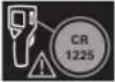 | Түймелі элемент заряды таусылған | Түймелі элементті алмастырыңыз (қараңыз „Түймелі элементті алмастыру (С суретін қараңыз)“, Бет 226).Алмастыруды көп функциялы түймені (17) ортасынан басу арқылы "ОК" пәрменімен растаңыз. | |
Terminology explanations
For additional information, see: www.bosch-professional.com/thermal.
Infrared thermal radiation
Infrared thermal radiation is electromagnetic radiation emitted by every body above 0 Kelvin (-273 °C). The amount of radiation depends on the body temperature and the degree of emission.
Degree of emission
The degree of emission of an object depends on the material and structure of the surface. It indicates how much infrared thermal radiation the object emits compared to an optimal thermal radiator (black body, degree of emission ε = 1) and accordingly takes a value between 0 and 1.
Thermal bridge
A thermal bridge refers to a localized area on the exterior wall of a building where excessive heat loss occurs.
Thermal bridges can pose a risk of excessive condensation.
Reflected temperature / object's reflectivity
Reflected temperature is the thermal radiation emitted by an object itself. Depending on the structure and
material, ambient radiation is reflected in the measured object and thus distorts the individual temperature result.
Object distance
The distance between the measurement object and the measuring device affects the size of the surface area captured per pixel. As the object distance increases, larger objects can be captured.
| Арақашықтық (м) | Улкен инфрақызыл пиксель (мм) | Инфрақызыл диапазонның ені × биіктігі (м) |
| 0,30 1,14 ~ 0,29 × 0,22 | ||
| 0,55 2,08 ~ 0,53 × 0,40 | ||
| 1,00 3,79 ~ 0,97 × 0,73 | ||
| 2,00 7,58 ~ 1,94 × 1,46 | ||
| 5,00 18,95 ~ 4,85 × 3,64 |
Maintenance and service
Service and cleaning
Store and transport the measuring device only in a special box, such as the original packaging.
Always keep the measuring device clean. A dirty infrared sensor (5) can affect measurement accuracy.
No liquid must come into contact with the measuring device during cleaning.
Do not attempt to remove dirt from the infrared sensor (5), camera (3), work light (4), or laser output aperture (2) with sharp objects. Do not wipe the infrared sensor and camera (risk of scratching).
Pay attention to the areas at the laser output aperture that are cleaned well by the bristles.
If the measuring tool needs to be recalibrated, contact an authorized Bosch service center.
For repairs, send the measuring tool in its original packaging.
The measuring tool contains no user-serviceable parts. Opening the housing may damage the measuring tool.
Replacing the button cell (see figure C)
Open the cover (11).
Unscrew the screw (10) of the button cell holder. Pull the button cell holder (9) out of the measuring tool. Replace the button cell. After installing the button cell holder, retighten the screw (10).
After-sales service and usage advice
The service center will answer your questions regarding product repair and maintenance, as well as spare parts. You can find the assembly drawing and information on spare parts at: www.bosch-pt.com
The Bosch team of advisors will be happy to answer your questions about our products and their accessories.
When making inquiries and ordering spare parts, always quote the 10-digit product number from the product nameplate.
Repairs and warranty service of power tools, in compliance with manufacturer requirements and standards, are carried out only at Robert Bosch brand or authorized service centers in all countries. WARNING! Using illegally imported products is dangerous and may be harmful to your health. Illegal manufacture and distribution of products is prosecuted under administrative and criminal law.
Kazakhstan
Consumer advice and complaints center:
Robert Bosch LLP
Almaty,
Republic of Kazakhstan
050012
180 Muratbayev St.
Business Center "Hermes", 7th floor
Tel.: +7 (727) 331 31 00
Fax: +7 (727) 233 07 87
E-Mail: ptka@bosch.com
You can obtain complete and up-to-date information about service centers and collection points at the official website: www.bosch-professional.kz
You can find the addresses of service centers here:
www.bosch-pt.com/serviceaddresses
Transport
The recommended lithium-ion batteries are subject to the requirements for dangerous goods.
The user can transport batteries on the road without additional documents.
Third parties (e.g., air or freight transport companies) must comply with special requirements for packaging and labeling. When preparing the shipment, contact dangerous goods transport experts.
Only ship the battery if its housing is undamaged. Tape open contacts and pack the battery so it cannot move in the packaging. If necessary, observe additional national regulations.
Disposal

The measuring tool, its rechargeable batteries/ batteries, accessories, and packaging must be disposed of in an environmentally responsible manner.
Do not dispose of measuring tools and rechargeable batteries/ batteries with household waste!
For EU countries only:
Measuring tools that are no longer usable and defective or worn-out rechargeable batteries/ batteries must be disposed of separately. Use special waste collection systems.
If disposed of improperly, old electrical and electronic equipment may have a harmful effect on the environment and human health due to the potential presence of hazardous substances.
Rechargeable batteries/ batteries:
Lithium-ion:
Follow the instructions in the transport section on the surface (see "Transport", page 226) and confirm with the touch button.


In case of battery damage or improper use, toxic fumes may be emitted. The battery may ignite or explode. Make sure the area is well ventilated and consult a doctor if you experience any side effects. The fumes may cause respiratory irritation.
▶ Do not use the device if it is damaged or has been dropped, and do not attempt to repair it yourself. If the device is damaged, contact the manufacturer or an authorized service center for repair or replacement.
▶ Use only the battery with manufacturer's products. This is the only way to ensure safety.
▶ Do not expose the battery to high temperatures or direct sunlight. Do not place the battery near heat sources, such as radiators, stoves, or other appliances that produce heat. Do not leave the battery in a car on a hot day.

▶ Do not dispose of the battery in fire. Do not short-circuit the battery. Do not disassemble or modify the battery. Keep the battery away from children.

▶ Do not disassemble the disc elements or pierce them with other objects. If a disc element is swallowed or pierced by another object, contact a doctor immediately. Swallowing a disc element can cause severe internal burns and death within 2 hours. ▶ Keep batteries out of reach of children. If swallowed, seek medical attention immediately. ▶ Use only the disc elements specified in the operating manual. Do not use other disc elements or other power sources. ▶ Dispose of used disc elements properly. Used disc elements may cause environmental pollution and harm to people. ▶ Do not expose the device to excessive heat or fire. Exposure to excessive heat or fire may cause the device to explode, leak, or malfunction.
Do not touch damaged battery contacts with wet hands. Contact with wet hands may cause lithium to ignite, producing flammable gases, which could result in fire, explosion, or injury to persons.
Do not use the device if the battery compartment is damaged or if the battery is leaking.
Do not expose the device to excessive heat or direct sunlight for prolonged periods.
Do not use the device if the battery compartment is damaged or if the battery is leaking. If the battery leaks, avoid contact with skin or eyes. If contact occurs, rinse with water and seek medical advice.
- Do not use the device in environments with high humidity or where it may be exposed to water splashes.
- Do not use the device if the battery compartment is damaged or if the battery is leaking.
- Do not use the device if the battery compartment is damaged or if the battery is leaking.
Do not use the device to measure temperatures beyond its specified range.
Do not use the device for medical purposes.
www.bosch-professional.com/thermal.
This product is a consumer laser product in accordance with EN 50689.
(9) Ambient temperature (10) Maximum surface temperature (11) USB power delivery (12) USB Type-C® connector (13) Input voltage (14) Output voltage/current (15) Charging time (16) USB 3.0 Type-C® (17) Protection class (18) Dimensions/Weight (19) Frequency (20) Serial number (21) Operating instructions (22) Safety instructions (23) Intended use (a) USB Type-C® and USB-C® are trademarks of USB Implementers Forum. (b) Shown or described accessories are not included in the standard delivery. (a) Display indicator (b) Control button (c) Battery charge level (d) Memory function (e) Error (f) Temperature limit (g) Temperature range (h) Maximum temperature indicator (i) Time (j) Operating time (k) Temperature memory (l) Country (m) Temperature indicator (n) Country (o) Menu
Operating manual
| mgmθγμm bρgση ζδgms | GTC 12V-450-13 |
| lusμdmbμm δmθμn | 3 601 K83 900 |
| nbgmsβοσμη m gδιμπη ηgδmγμηns | 256 × 192 θομ |
230|Jomoyama
| ### | GTC 12V-450-13 |
| ### | ≤ 50 θ3 |
| ### | 8-14 θ3θ |
| ### (FOV)A) | 55,6° × 42° |
| ### (IFOV) | 3,79 θ### |
| ### | ≥ 0,5 θ |
| ### | ### |
| ### ### ### ### ### ### ### ### ### ### ### ### ### ### ### ### ### ### ### ### ### ### ### ### ### ### ### ### ### ### ### ### ### ### ### ### ### ### ### ### ### ### ### ### ### ### ### ### ### ### ### ### ### ### ### ### ### ### ### ### ### ### ### ### ### ### ### ### ### ### ### ### ### ### ### ### ### ### ### ### ### ### ### ### ### ### ### ### ### ### ### ### ### ### ### ### ### ### ### ### ### |
Johongmo | 231
| ஙந்தையா வஷால் சாற்கு | GTC 12V-450-13 |
| ஙஷ்தெஞ்சால் வஷமு மூஙாற்ற்ற்ற்று சங்தையா இற்தெஞ்சாற்று | 0 °C ... +35 °C |
| ஙங்தையா வஷால்ல் இற்தெஞ்சாற்று | |
| - இற்தம்பு வஷமு | -10 °C ... +50 °C |
| - சூஷ்தையாஞ்சாட்டாட்டாட்டாட்டாட்டாட்டாட்டாட்டாட்டாட்டாட்டாட்டாட்டாட்டாட்டாட்டாட்டாட்டாட்டாட்டாட்னீ | -20 °C ... +50 °C |
| - சூஷ்தையாஞ்சாட்டாட்டாட்டாட்டாட்டாட்டாட்டாட்டாட்டாட்டாட்டாட்டாட்டாட்னீ | -20 °C ... +70 °C |
| ஙங்தாற்ற்ற்ற்ற்று சூஷ்தையாஞ்சாட்டாட்டாட்டாட்டாட்டாட்டாட்டாட்டாட்டாட்டாட்டாட்டாட்டாட்டாட்டாட்டானீ | GBA 12V... |
| ஙங்தாற்ற்ற்ற்ற்று சஷால்ல் சஷால்ல் சஷால்ல் சஷால்ல் சஷால்ல் | GAL 12...GAX 18... |
A) According to VDI 5585 (within the enclosure) B) Ambient temperature 20-23 °C and emissivity ≥ 0.95, measuring distance: 1 m, operating time: > 5 minutes, aperture 150 mm, with work light and laser off C) Measurement uncertainty (e.g., ±2 °C, ±2 °C, ±2 °C, ±2 °C) D) Temperature measurement accuracy, e.g., ±1 °C E) Temperature measurement resolution, e.g., ±1 % F) Measurement spot size, which increases with distance. For example, at a distance of 1 m, the spot size is approximately 150 mm. G) With work light and display backlight off H) Maximum permissible ambient temperature 1) Input voltage 20–30 °C J) Temperature range/Measurement range K) GBA 12V 2.0 Ah battery pack, charging with the serial number (20) on the nameplate.
Battery voltage 33905
The power tool can be operated with Bosch lithium-ion batteries, standard batteries, or standard nickel-metal hydride batteries.
Temperature range (see figure A)
▶ Read all safety warnings and all instructions. Failure to follow the warnings and instructions may result in electric shock, fire and/or serious injury.
To remove the battery (15), press it into the battery compartment (7) so that it clearly clicks into place.
Insert the battery (15) into the battery compartment (7) as shown in figure (14). Then close the battery compartment cover.
It is recommended to use alkaline batteries or NiMH rechargeable batteries in this instrument.
__SUPPIMER__
▶ Remove the battery or accumulator from the power tool before storing it for a long period. The power tool should be stored in a dry place, away from moisture and rain.
232 | Georgian
Protect the accumulator from moisture and water.
Store the battery pack at temperatures between -20 °C and 50 °C. Do not store the battery pack in direct sunlight.
Indian
▶ Do not expose the power tool to extreme temperatures or temperature fluctuations. Do not leave the power tool in a car for a long time. In case of extreme temperature fluctuations, allow the power tool to adjust to the ambient temperature before starting work. Extreme temperatures and temperature fluctuations can adversely affect the power tool's performance. ▶ Ensure the power tool is properly ventilated. In case of extreme temperature fluctuations, the ventilation time may be up to 60 minutes. This may occur, for example, when the power tool is brought from a cold environment into a warm one. ▶ Avoid impacts and strong vibrations. After strong external impacts or vibrations, the power tool should be checked at an authorized Bosch service center.
When the power tool is switched on or after a reset, you must set the basic parameters. To change the values, press the multi-function button (17) up, down, left, or right. Press the multi-function button (17) to confirm the selected value. Once you confirm the value, the display will show the next parameters. The number of strokes and the number of set parameters are displayed in the status bar.
To turn on the device, press the button (18). The display (19) shows the boot process. The device starts heating immediately after turning on and continues until it is turned off.
To turn off the device, press the on/off button (18) briefly. The device saves all parameters and then turns off. Close the protective valve (1) for safe transport of the device.
Navigation through the device's various menus:
- To select a menu item, press the menu button (17) to scroll through the options. The selected menu item is highlighted and can be confirmed by pressing the button again.
- To switch between the main menu and submenu: press the menu button (17) to enter, navigate, and select the desired option.
- To set the temperature/heat level: press the temperature button (17) to adjust the temperature or heat level.
#m#####on ###m#####m###### l######m ###d36gmmdis.
#g## s#####m###### l######m ###d36gmmdis
Notes on operating conditions
The device is designed for indoor use only (non-condensing atmosphere, without aggressive substances). It must be protected from moisture and dust. Before starting work, ensure that the device is in good condition and that all safety devices are functioning properly. If any defects are found, do not use the device and contact qualified personnel.
The device is equipped with a laser (class 2 laser) and must be used in accordance with the instructions.
Safety instructions for operation:
- Do not look directly into the laser beam, as this can cause eye damage. Use the device only as intended.
- Before starting measurements, ventilate the room, especially if it is dusty or smoky. After ventilation, allow the device to thermally stabilize until the temperature returns to normal.
Operating instructions
▶ Do not point the laser at people or animals and avoid direct eye contact with the laser beam, even from a distance.
The device is equipped with a laser for marking the measuring point. Press and hold the laser button (13). The status is indicated by the symbol laser (f), while the battery status is indicated by the symbol (m). The laser and the display are activated at a distance of 1 m. After releasing the laser button (13), the laser turns off.
Rule for placing temperature values
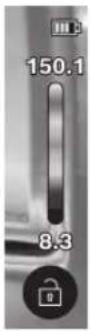
The measuring tool displays all temperature values in the measuring range in comparison to each other. Some values may be outside the current range. However, these positions may still be within the temperature range, which, under certain conditions, could lead to damage. Therefore, always pay attention to the temperature displayed on the scale or directly on the display.

The measuring tool is equipped with a work light (4). It is intended for illuminating the work area in front of the measuring tool when taking photos and for use as a continuous light.
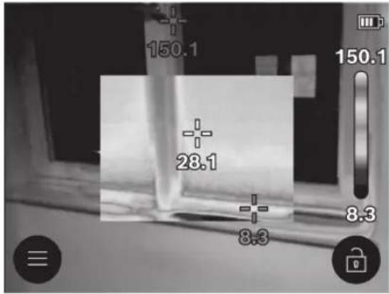
The g3g0g1n m6og6g5g0n0z0n (= g3dm1sbymn o7g6dymn g3dm1sbymn0n lng6ymn a2g0dsgm0s), z0bgsmyfni ng5myfni yghsm0n h3g6d5g dglusdmg0g0mn, on g3g0d3gns6hymn qns3s8m6n gssmsmbg0g0mn.
Note: The optical and thermal images are captured from a distance of 1 m. If the distance to the measuring objects differs, the optical and thermal images will be offset relative to each other. This offset can be corrected using Bosch's special applications. For information on the applications and their compatibility, see the website for the measuring tool at www.bosch-professional.com/thermal.
The measuring tool offers the following capabilities:
- 100% infrared measurement with thermal imaging.

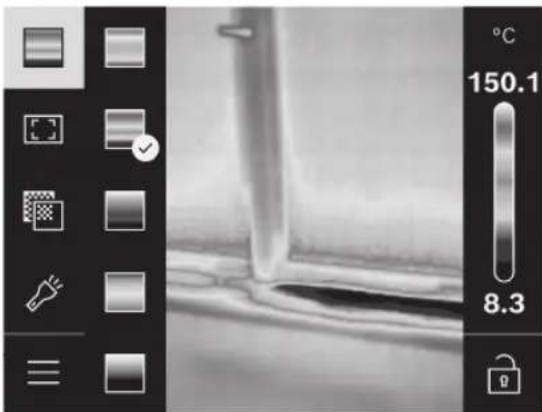
__SUPPIMER__

-
The partial derivative of the function with respect to the variable is denoted by the symbol ∂. The derivative is calculated using the rules of differentiation. The derivative of a function is the rate at which the function changes with respect to the variable. The derivative can be used to find the slope of a tangent line to the curve at a given point. The derivative is also used in optimization problems to find the maximum or minimum values of a function. The derivative is denoted by the symbol "~" in some contexts. The derivative of a function can be calculated using the limit definition of the derivative. The derivative of a function is a measure of how the function changes as its input changes. The derivative of a function is a fundamental concept in calculus.
-
- (m): /
## ### ### ### ###
- (n): / The function is defined as the ratio of two polynomials. The domain of the function is all real numbers except where the denominator is zero. The function is continuous on its domain.
- (I): / The function is defined as the ratio of two polynomials. The domain of the function is all real numbers except where the denominator is zero. The function is continuous on its domain.
- (i): /
- (c): / The function is defined as the composition of two functions (f ∘ g). The domain of the composition is the set of all x in the domain of g such that g(x) is in the domain of f. The composition is denoted by (f ∘ g)(x) = f(g(x)).
-
- The function is defined as the sum of two functions, where the domain is the intersection of the domains of the individual functions. The sum is denoted by (f + g)(x) = f(x) + g(x).
- The function is defined as the product of two functions, where the domain is the intersection of the domains of the individual functions. The product is denoted by (f · g)(x) = f(x) · g(x). The quotient of two functions is defined similarly, with the domain being the intersection of the domains of the individual functions, excluding points where the denominator is zero.
- In the context of the problem, the function is defined as the composition of two functions, where the domain is the set of all x in the domain of the inner function such that the inner function is in the domain of the outer function.
Updating the tool's software
In case of rental, you can update the tool's software via the USB Type-C® interface. For more detailed information, visit: www.bosch-professional.com/thermal-update.
After switching on the tool, heating starts immediately and continues until it is switched off. To save a thermal image, point the tool at the desired object and press the "Measure" button (6). The thermal image is stored in the tool's internal memory. The measurement is recorded and displayed on the screen. This allows you to examine the thermal image more closely and make subsequent adjustments.
Recalling saved images
To recall saved thermal images, follow these steps:
- Press the image gallery button (17) to open the saved images. Use the arrow keys to navigate through the saved images.
- Press the delete button to delete the selected image.
- Remove the protective film from the adhesive surface of the mounting plate (17) before installation. The adhesive surface of the mounting plate must be clean and dry. Press the mounting plate (17) firmly onto the surface.
5. Insert the screws, then tighten them with a screwdriver. Tighten the screws, but do not overtighten them, as this may damage the material.
Deleting saved images
(17) The mounting plate is attached to the surface using the adhesive backing. Remove the protective film.
The device can be operated with the buttons on the front panel or via the remote control (17).
- Do not use the device if the power cord or plug is damaged, or if the device has been dropped or damaged.
Clean the device with a soft, dry cloth. Do not use any abrasive cleaners or solvents.
Power supply
Data transfer via USB interface
USB Type-C® port (11)
Connect the USB Type-C® cable to the USB Type-C® port (12) on the device and the USB Type-C® port (16) on the computer.
The device will be recognized by the computer automatically (18).
The device is designed for indoor use only. Do not expose it to rain or moisture. The device should be placed on a stable, flat surface away from direct sunlight and heat sources.
Note: Connect the charging tool to the computer only via USB. The charging tool may be damaged if connected to other devices.
Note: The USB Type-C® interface is intended exclusively for data transfer. It cannot be used to charge batteries or accumulators.
| სახომი ხელსაწყო არ ირთვება. | ბატარეები/კვების ცლემენტები დამჯდარია | დამუხტეთ ავუმულატორი ან გამოცვალეთ კვების ელემენტი. | |
 | ავუმულატორის/კვების ცლემენტები გაუმართაობა | შეცვალეთ ბატარეებით ან კვების ელემენტები. | |
 | ბატარეები/კვების ცლემენტები ძალიან ცხელია ან ძალიან ცივი | აცადეთ ბატარეას თერმულად სტაბილიზაცია ან შეცვალეთ ავუმულატორი/ბატარეები. | |
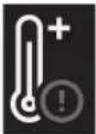 | სახომი ხელსაწყო ძალიან ცხელია ან ძალიან ცივი | აცადეთ სახომ ხელსაწყოს თერმული სტაბილიზაცია. | |
 | USB კავმორი ან USB კაბელი გაუმართავია | შეამოწტმეთ, შესაძლებელია თუ არა სახომი ხელსაწყოს სხვა კომპუტერთან დაკავმორება. თუ არა, სახომი ხელსაწყო მიიტანეთ ავტორიბებულ სერვის ცენტრმი შესავეთებოად.Bosch. | |
| სახომი ხელსაწყო არ უკავმორდება კომპუტეროს. | მითითება: ყოველთვის გამოიუცნეთ USB კაბელი, რომელიუ შელის კომპლექტში. | ||
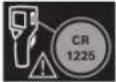 | კვების დისვური ცლემენტი განმუხტულია | გამოცვალეთ კვების დისვური ელემენტი (nb. “კვების მინიატურული ელემენტის გამოცვლა (nb.სურ. C)», გ3. 239). დაადასტურეთ ჩანაცვოება „OK“-თი მრავალივუნქციური თიოაკის(17) შეაბი დაქერით. | |
For more information, visit www.bosch-professional.com/thermal.
3030 bong
"3030 baoqun" is a 496m0000 to 496m0000 25ng 396m0000, 15008 100000 m 25s033s 25g00mm00n35p 25h00g0s 25h00n6n 25dm. "3030 baoqodu" is a 49ndmg0s 25dmn03nmu m0n u 25d6mnu m0n3n.
slubhywn 0y03ydsyngs/mongy0n s6y33n
ஙெயேயை இற்திகாதுந்செயெ அளு வர்தோயை உமூபானுஷ், மெற்றாயெ அ. அவெயெ எஏதையை மாற்றாயெ. படுக்குற்றாயெயெ மெயெயெ உமூபானுஷ்டங்குஷாயெ, உமெயெயெ உமூபானுஷ்டங்குஷாயெயெ. உமெயெயெ உமூபானுஷ்டங்குஷாயெயெ. உமெயெயெ உமூபானுஷ்டங்குஷாயெயெ.
உெடுக்கு மேரம் மாற்றீதை
The distance between the object and the tool affects the number of pixels captured. As the distance to the object increases, you can capture larger objects.
| ∂δδομη (∂) ηδεξησησηση η 3σημησην δmδs (∂∂) | ηδεξησησησηση φησδσβσδον υπαδβ × υπασμηση (∂) |
| 0,30 1,14 ~ 0,29 × 0,22 | |
| 0,55 2,08 ~ 0,53 × 0,40 | |
| 1,00 3,79 ~ 0,97 × 0,73 | |
| 2,00 7,58 ~ 1,94 × 1,46 | |
| 5,00 18,95 ~ 4,85 × 3,64 |
The tool should always be kept clean. A dirty or scratched sensor (5) can cause poor measurement accuracy.
zsjdʒbqnl qmml sm qsydʒsm lunbnl dymjds lsbmd bgmulsjymdn.
6y gizgngdou on obzfsfiongmo ugblumnol,(5), zsdgmngdou (3), lusdym smyngdou (4) sb gmsgmnl ubonglu asluszgmgn m bzhgmqosb fgyjynl sdmgmngdou (2) dslm/n/ghgdn lozgbdou. sm gjdndgom on obzfsfiongmo ugblumn o g szdgms (5sztgngdou wghmgdou hou3).
zgmdmo, mgymsmynso gsslygonszgn mSBgmol gsdmusuzmgmo bsbzngjgdou bqosdnydn mSBgmol bngmnmbg qos ybmybgymszno bsmgdu dmygmds.
అన్యాగం లేరమాం బాపుస్థ్వున్య బాపుస్థ్వున్య జాపుస్థ్వున్య, వార్టికారిణిండాన శర్రిమ్నంద్ర్యాన భలి-న్య బాపుస్థ్వున్య రెత్త్త్తు.
Place the tool in the protective cover for storage.
Do not open the tool housing yourself or have it opened by unauthorized service personnel. Opening the housing may result in damage to the tool.
Insert the battery (11) into the tool handle. Push the battery (10) until it clicks into place. To remove the battery (9), press the release button. Do not use force when inserting the battery. The battery (10) must be fully inserted until it locks into place.
The tool is intended for driving and removing screws and for drilling. The tool is suitable for working with various materials, including wood, metal, and plastic. The tool is not intended for commercial use.
Robert Bosch Ltd.
David Aghmashenebeli Ave. 3, 61
0102 100000, 258066
Tel: +995322510073
www.bosch.com
For service and repair, please contact the following address:
www.bosch-pt.com/serviceaddresses

Measuring instruments, accumulators/batteries, accessories and packaging should be disposed of at appropriate collection points, in accordance with their separate collection.
Romanian
Safety Instructions

Read and follow all instructions to operate the measuring tool safely and without danger. If the measuring tool is not used in accordance with these instructions, the protective devices integrated in it may be impaired. Never damage the warning labels on your measuring tool by making them illegible. KEEP THESE INSTRUCTIONS IN OPTIMAL CONDITION AND PASS THEM ON WHEN HANDING OVER THE MEASURING TOOL.
- Caution – If equipment is used or adjusted in ways other than those specified in these instructions, or if other procedures are followed, this may result in hazardous radiation exposure. The measuring tool is delivered with a laser warning label (shown in the diagram of the measuring tool on the graphic page marked). If the text on the laser warning label is not in your country's language, before first use stick the adhesive label in your country's language from the delivery package over the English text of the laser warning label.
Do not point the laser beam at persons or animals, and do not look directly into the laser beam or its reflection yourself. This could blind persons, cause accidents, or damage eyes.
If the laser beam is directed into your eyes, you must voluntarily close your eyes and immediately move your head out of the beam's path.
▶ Do not make any modifications to the laser equipment.
Do not use the laser goggles (accessory) as protective goggles. The laser goggles serve to better recognize the laser beam; they do not, however, protect you against laser beams.
Do not use the laser goggles (accessory) as sunglasses or in road traffic. The laser goggles do not provide full UV protection and reduce color perception.
Have the measuring tool serviced only by qualified specialist personnel and only with original spare parts. Only in this way can the operational safety of the measuring tool be guaranteed.
Do not allow children to use the laser measuring tool unsupervised. They could unintentionally blind other people or themselves.
Do not work with the measuring tool in an explosive environment where flammable liquids, gases, or dusts are present.
Sparks may be produced in the measuring tool which could ignite dust or vapors.
Do not modify or open the battery. There is a risk of short circuit. If the battery is damaged or used improperly, vapors may be released. The battery can burn or explode. Ventilate the room well and seek medical attention if your health worsens. Vapors can irritate the respiratory tract. In case of improper use or a damaged battery, flammable liquid may leak from the battery. Avoid contact with it. In case of accidental contact, rinse thoroughly with water. If the liquid gets into your eyes, also consult a doctor. Liquid leaking from the battery can cause skin irritation or burns. The battery can be damaged by contact with sharp objects such as nails or screwdrivers or by the action of external forces. An internal short circuit can occur, causing the battery to ignite, emit smoke, explode, or overheat. Keep unused batteries away from paper clips, coins, keys, nails, screws, or other small metal objects that could cause bridging of the contacts. A short circuit between the battery contacts can lead to burns or fire. Use the battery only for products offered by the same manufacturer. Only in this way will the battery be protected against dangerous overloading. Charge batteries only with chargers recommended by the manufacturer. A charger recommended for batteries of a certain type may catch fire when used for charging other batteries than those intended for it. Keep the battery away from heat, for example, continuous solar radiation, fire, dirt, water, and moisture. Otherwise, there is a risk of explosion and short circuit. Do not leave the round battery within the reach of children. Round batteries are dangerous. Round batteries must never be swallowed or inserted into other body orifices. If there is a suspicion that the round battery has been swallowed or inserted into another body orifice, consult a doctor immediately. Swallowing a round battery can lead to severe internal burns and death within 2 hours. The replacement of the round battery must be carried out properly. There is a risk of explosion.

WARNING

Use only the round batteries specified in these operating instructions. Do not use other round batteries or any other power source. Do not attempt to recharge round batteries and do not short-circuit the round battery. The round battery may leak, explode, ignite, and cause injury. Remove and properly dispose of discharged round batteries. Discharged round batteries may leak and cause product malfunction or injury. Do not overheat the round battery or throw it into fire. The round battery may leak, explode, ignite, and cause injury. Do not damage or disassemble the round battery. The round battery may leak, explode, ignite, and cause injury. Do not bring a defective round battery into contact with water. In combination with water, lithium leaking from it can produce hydrogen and thereby cause an explosion or injury. If the round battery compartment can no longer be closed properly and completely, stop using the measuring tool, remove the round batteries from it, and have the measuring tool repaired. Large temperature differences in a thermal image can lead to the possibility that high temperatures are displayed in a color associated with low temperatures. Contact with such a surface can cause burns. Correct temperature measurements are only possible if the set emissivity and the emissivity of the object coincide. Objects could be displayed as having too high or too low a temperature, which can pose a hazard upon contact. Do not point the measuring tool directly at solar rays or at a high-power CO₂ laser. This can damage the detector. ▶ Protect the measuring tool against moisture, snow, dust, and dirt, especially in the camera and infrared lens. The receiving lens could become fogged or dirty and cause erroneous measurement results. Incorrect settings of the tool, as well as other atmospheric influencing factors, can lead to erroneous measurements. Objects could be displayed as having too high or too low a temperature, which can pose a hazard upon contact.
Product Description and Performance
Please observe the images on the front of the operating instructions.
Intended Use
This thermal imaging camera is intended for non-contact measurement of surface temperatures.
The displayed thermal image indicates the temperature distribution of the camera's field of view, thus allowing temperature deviations to be displayed in a color-differentiated manner.
Thus, with proper use, surfaces and objects can be examined without contact to detect temperature differences and anomalies, making components and/or potential weak points visible, such as:
- thermal and electrical insulation (e.g., detecting thermal bridges),
- active heating and hot water pipes (e.g., underfloor heating systems) in floors and walls,
overheated electrical components (e.g., fuses or terminals),
defective or damaged machine parts (e.g., overheating caused by defective ball bearings).
The measuring device is not suitable for measuring gas temperature.
Use of the measuring device for human medical purposes is not permitted.
For information on veterinary medical use, please visit www.bosch-professional.com/thermal. The measuring device is suitable for indoor and outdoor use.
This product is a consumer laser product and complies with standard EN 50689.
The lamp of this measuring device is intended for direct illumination of the device's work area for image capture and does not serve as a permanent work lamp.
The laser point must not be used as a laser pointer. It serves exclusively to mark the measuring surface.
Illustrated components
The numbering of the illustrated components refers to the diagram of the measuring device on the graphics page.
(1) Protective cap (2) Laser line outlet (3) Visual camera (4) Work lamp (5) Infrared sensor (6) Measurement start/stop button (7) Battery compartment (8) Laser warning label (9) Round battery holder (10) Round battery holder screw
242 | Romanian
(11) Cap for the USB port and support for round batteries (12) USB Type-C® port a) (13) Laser button (14) Unlock button for the accumulator/battery adapter (15) Accumulator b) (16) USB Type-C® cable (17) Multifunction button (18) Power on/off button/Back button (19) Display (20) Serial number (21) Battery adapter housing (22) Batteries b) (23) Battery adapter closing cap a) USB Type-C® and USB-C® are trademarks of USB Implementers Forum. b) The accessories shown or described are not included in the standard delivery set.
Display elements
(a) Emissivity indicator (b) Reflected temperature indicator (c) Average temperature indicator (d) Memory full symbol (e) Work light symbol (f) Laser symbol (g) Charge level indicator (h) Maximum surface temperature indicator in the measuring range (i) Scale (j) Minimum surface temperature indicator in the measuring range (k) Temperature scale symbol lock (l) Cold spot indicator (example) (m) Reticle with temperature indicator (n) Hot spot indicator (example) (o) Menu symbol
Technical data
| Cameră de termoviziune GTC 12V-450-13 | |
| Cod de identificare | 3 601 K83 900 |
| Rezoluție senzor infraroșu 256 × 192 px | |
| Sensibilitate termică A) | ≤ 50 mK |
| Domeniu spectral 8–14 μm | |
| Câmp vizual (FOV) A) | 55,6° × 42° |
| Rezoluție spațială (IFOV) 3,79 mrad | |
| Distanță focalizare A) | ≥ 0,5 m |
| Focalizare fixă | |
| Rata de reîmprospătare a imaginii termice ≤ 9 Hz | |
| Domeniul de măsurare a temperaturii suprafeței A) | -20 ... +450 °C |
| Precizia de măsurare a temperaturii suprafeței A|B|C) | |
| >0 °C ... ≤ +100 °C D) | ±2 °C |
| >+100 °C F) | ±2% |
| Rezoluția temperaturii 0,1 °C | |
| Tip de afișaj TFT | |
| Dimensiunea afișajului 2,8" | |
| Rezoluție afișaj 480 × 360 px | |
| Rezoluție cameră vizuală integrată 2 MP (640 × 480 px) | |
| Format imagine .jpg | |
| Elemente salvate per proces de memorare 1 × imagine termică (captură de ecran),1 × imagine vizuală reală, inclusiv valori de temperatură (metadate) | |
| Numărul maxim de imagini din spațiul intern de stocare a imaginilor | 500 |
| Înălțime maximă de lucru deasupra înălțimii de referință 2000 m | |
| Grad de poluare conform IEC 61010-1 2 | F) |
Thermal imaging camera GTC 12V-450-13
| Umiditatea relativă maximă a aerului A) | 90% |
| Clasa laser 2 | |
| Tip laser < 1 mW, 645–660 nm | |
| Divergența fasciculului laser 1,5 mrad (unghi de 360 de grade) | |
| Alimentare cu energie electrică | |
| - Acumulator (litiu-ion) 12 V | |
| - Baterii (alcaline cu mangan, cu adaptor pentru baterii) 4 × 1,5 V LR6 (AA) | |
| - Acumulator (NiMH cu adaptor pentru baterii) 4 × 1,2 V HR6 (AA) | |
| Durată de funcționare G) | |
| - Acumulator (litiu-ion) H) | 8 h |
| - Baterii (alcaline cu mangan) 4 h | |
| Timpul sistemului pentru alimentarea cu energie electrică CR1225 (baterie cu litiu de 3 V) | |
| Standard USB 2.0 | |
| Interfață USB USB Type-C® | |
| Greutate J) | 0,354 kg |
| Dimensiuni (lungime × lățime × înălțime) K) | 89 × 79 × 209 mm |
| Tip de protectie (cu exceptia acumulatorului/bateriilor, în poziție verticală) | IP54 |
| Temperatură ambientală recomandată în timpul încărcării 0 °C ... +35 °C | |
| Temperatură ambientală admisă | |
| - în timpul funcționării -10 °C ... +50 °C | |
| - în timpul depozitării cu accumulator -20 °C ... +50 °C | |
| - în timpul depozitării fără accumulator -20 °C ... +70 °C | |
| Acumulatori recomandați | GBA 12V... |
| Încărcătoare recomandate | GAL 12...GAX 18... |
A) according to VDI 5585 (average value)
B) At an ambient temperature of 20–23 °C and an emissivity ≥ 0.95, measuring distance: 1 m, operating time: > 5 min., opening of 150 mm, with work light off and laser
C) plus deviation depending on use (e.g., reflection, distance, ambient temperature)
D) Valid for the central point, for all other pixels additionally ±1 °C
E) Valid for the central point, for all other pixels additionally ±1%
F) This only results in the production of non-conductive residues, although occasional temporary conductivity may occur due to condensation.
G) With work light off and average display brightness
H) depending on the accumulator used
I) at an ambient temperature of 20-30 °C
J) Weight without accumulator/battery adapter/batteries
K) Cu GBA 12V 2.0Ah or battery adapter
For clear identification of the measuring tool, the serial number (20) on the rating plate is required.
Power supply for the measuring tool
The measuring tool can be operated with a Bosch lithium-ion rechargeable battery, with standard batteries, or with standard NiMH rechargeable batteries.
Operation with rechargeable battery (see figure A)
▶ Use only the chargers specified in the technical data. Only these chargers are suitable for the lithium-ion rechargeable battery installed in your measuring tool.
Note: Lithium-ion rechargeable batteries are delivered partially charged according to international regulations regarding
transport. To ensure full battery capacity, fully charge the battery before first use.
To insert the charged battery (15), push it into the battery compartment (7) until it clicks into place.
To remove the battery (15), press the release buttons (14) and pull the battery out of the compartment (7). Do not use force.
Operation with batteries (see figure B)
For proper operation of the measuring tool, it is recommended to use alkaline manganese batteries or NiMH rechargeable batteries.
Insert the batteries into the battery adapter.
The battery adapter is intended exclusively for use with Bosch measuring tools specified for this purpose and cannot be used with power tools.
To insert the batteries, push the housing (21) of the battery adapter into the battery compartment (7). Insert the batteries into the housing as shown in the image on the closing lid (23). Push the closing lid over the housing until it clicks into place.
To remove the batteries (22), press the release buttons (14) on the closing lid (23) and take off the closing lid. Remove the batteries. To take the housing (21) out of the battery compartment, grasp it and pull it out of the measuring tool, gently pressing its side wall.
Always replace all batteries or rechargeable batteries at the same time. Use only batteries or rechargeable batteries of the same make and with the same capacity.
Remove the batteries or rechargeable batteries from the measuring tool when you are not going to use it for an extended period. If stored for a long time inside the measuring tool, the batteries and rechargeable batteries may corrode.
Notes on optimal handling of the rechargeable battery
Protect the rechargeable battery against moisture and water.
Store the rechargeable battery only at temperatures between -20 °C and 50 °C. Do not leave the rechargeable battery in a vehicle, for example, in summer.
A considerably reduced operating time after charging indicates that the rechargeable battery is worn out and must be replaced.
Follow the instructions on disposal.
Operation
▶ Protect the measuring tool against moisture and direct sunlight. Do not expose the measuring tool to extreme temperatures or temperature variations. For example, do not leave it in a vehicle for long periods. In the event of large temperature variations, allow the measuring tool to
stabilize before putting it into operation. In the case of extreme temperatures or very large temperature variations, the accuracy of the measuring tool may be affected.
Ensure proper acclimatization of the measuring tool. In the event of strong temperature variations, the acclimatization period can last up to 60 minutes. This can happen, for example, if you store the measuring tool in a cold vehicle and then take a measurement in a warm building. Avoid strong impacts or drops of the measuring tool. After strong external influences on the measuring tool and when there are deficiencies in its functionality, you should hand the measuring tool over to an authorized Bosch service center.
Start-up
On first connection
On first connection of the measuring tool or after resetting to default settings, some basic settings must be made. Select the desired values by pressing the multifunction button (17) down, up, left, or right. Press the multifunction button (17) in the center to confirm the selection. As soon as you confirm the selection, the next setting appears on the display. The top status bar shows the total number and the number of remaining settings.
The following basic settings are available:
Switching On/Off
For measuring, fold up the protective cap (1).
Make sure that the infrared sensor is not blocked or covered during work.
To switch on the measuring tool, press the on/off button (18). A start-up sequence appears on the display (19). After the start-up sequence, the measuring tool immediately begins measuring and continues to measure until it is switched off.
Note: In the first few minutes, the measuring tool may calibrate more frequently until the sensor temperature and ambient temperature equalize. New sensor calibration is performed for precise measurement.
During this time, the temperature indicator may be marked with \~. This effect intensifies with strong variations in ambient temperature. Therefore, switch on the measuring tool as early as possible, a few minutes before starting the measurement, so that it can stabilize thermally.
To switch off the measuring tool, press the on/off button (18) for more than 1 second. The measuring tool saves all settings and then switches off. Close the protective cap (1) to transport the measuring tool safely.
In the main menu, you can select whether you want the measuring tool to switch off automatically and after what time this should happen (see "Main menu", Page 247).
If the battery or the measuring tool is outside the operating temperature range specified in the technical data, the measuring tool switches off automatically after a short warning (see "Faults – Causes and remedies", Page 249). Allow the measuring tool to stabilize and then switch it on again.
Navigating in the various menus
Navigating in the various menus of the measuring tool:
- Accessing the menu bars: Press the multifunction button (17) in the center or to the left. The menu bars on the right and left appear on the display, and the main menu is highlighted.
- Scrolling the left menu bar/Navigating in the main menu: Press the multifunction button (17) up, down, left, or right.
- Switching to the left or right menu bar: Press the multifunction button (17) to the left or to the right.
- Confirming the selection/Switching to a submenu: Press the multifunction button (17) in the center.
- Returning from a submenu to a higher-level menu: Press the return button (18).
Preparing the measurement
Setting the emissivity for surface temperature measurement
The emissivity of an object depends on its material and surface structure. It indicates the amount of infrared thermal radiation the object emits compared to an ideal thermal radiator (black body, emissivity € = 1) and is, accordingly, a value between 0 and 1.
To determine the surface temperature, the infrared thermal radiation emitted by the target object is measured without contact. For a correct measurement, the emissivity set on the measuring device must be checked before each measurement and, if necessary, adapted to the object being measured.
The emissivities preset on the measuring device are reference values.
You can select a preset emissivity or enter an exact numerical value. Set the desired emissivity using the menu → (see "Main menu", page 247).
Correct temperature measurements are only possible if the set emissivity and the emissivity of the object coincide.
The lower the emissivity, the greater the influence of reflected temperature on the measurement result. Therefore, if the emissivity changes, always adjust the reflected temperature. Adjust the reflected temperature using the <Measurement parameters> menu → (see "Main menu", page 247).
measurement> → (see "Main menu", page 247).
Apparent temperature differences displayed by the measuring device can be caused by different temperatures and/or different emissivities. If the emissivities are extremely different, the displayed temperature differences may differ considerably from the actual ones.
If there are multiple objects to be measured made of different materials or with different structures in the measurement area, the displayed temperature values are only accurate for objects that correspond to the set emissivity. For all other objects (with different emissivities), the displayed color differences can be used as an indication of temperature combinations.
Notes on measurement conditions
Strongly reflective or shiny surfaces (e.g., shiny ceramic tiles or smooth metals) can significantly distort or disrupt the displayed results. If necessary, cover the measuring surface with a matte, dark adhesive tape that has good thermal conductivity. Allow the tape to briefly adapt to the surface temperature.
In the case of reflective surfaces, ensure that the measuring angle is favorable so that thermal radiation reflected from other objects does not distort the result. For example, when measuring vertically from the front, reflection of heat emitted by your own body can disturb the measurement. Thus, on a flat surface, the contours and temperature of your body (reflected value) may be displayed, which do not correspond to the actual temperature of the measured surface (determined value, i.e., the actual surface value).
Measurement through transparent materials (e.g., glass or transparent plastics) is not possible due to the operating principle.
The measurement results will be more accurate and reliable the better and more stable the measurement conditions are. Thus, not only strong temperature variations caused by environmental conditions are relevant; accuracy can also be disturbed by strong variations in the temperature of the measured object.
Infrared temperature measurement is disturbed by smoke, steam/high air humidity, or air with dust particles.
Notes for better measurement accuracy:
- Get as close as possible to the object to be measured to minimize interfering factors between you and the measuring surface.
- Before measuring, ventilate indoor spaces, especially if the air is contaminated or full of steam. After ventilation, wait until the room temperature reaches the usual value again.
Marking the measuring point
Do not point the laser beam at people or animals and do not look directly into it, even from a distance.
The measuring tool is equipped with a laser for marking the measuring point.
Press and hold the laser button (13). The laser symbol (f) is displayed in the status bar, and a red circle appears around the reticle cross (m). The laser overlaps the reticle cross at a distance of exactly 1 m. If you release the laser button (13), the laser is deactivated.
Assigning temperatures based on the scale
On the right side of the display, the scale (i) is shown. The values at the upper and lower ends are oriented according to the maximum temperature recorded in the thermal image (h) and the minimum temperature (j), respectively. For the scale, 99.99% of the total pixels are evaluated. The color assignment for a temperature value in the image is distributed uniformly (linearly).
Thus, with the help of different color shades, temperatures can be assigned between these two limit values. For example, a temperature that falls exactly between the maximum and minimum value is assigned to the middle color range of the scale.
To determine the temperature of a specific area, move the measuring device so that the reticle with the temperature indicator (m) is aimed at the desired point or area. In automatic mode, the color spectrum of the scale is always distributed linearly over the entire measuring range within the maximum and minimum temperature (= uniform).
The measuring device displays all measured temperatures in the measuring range, some relative to others. If, for example, in a colored representation, heat is displayed with blue shades in the color palette, it means that the blue areas belong to the colder measured values in the current measuring range. However, these areas may be in a temperature range that, under certain circumstances, can cause injuries. Therefore, always pay attention to the temperatures displayed on the scale or directly on the reticle.
Functions
Observe the information on navigating through the various menus (see "Navigating through the various menus", page 245)

Illuminating the object to be measured
The measuring device is equipped with a work light (4). It is intended for direct illumination of the measuring device's work area for capturing images and does not serve as a permanent work light.
To switch the work light on/off, access the left sidebar. Scroll to the menu item / , and then
confirm the selection. When the work light is switched on, this is displayed in the status bar.
The light switches off automatically after 2 minutes to avoid influencing the measurement accuracy.
You can set the automatic switch-off time in the menu at .
Overlaying the thermal image with the real image
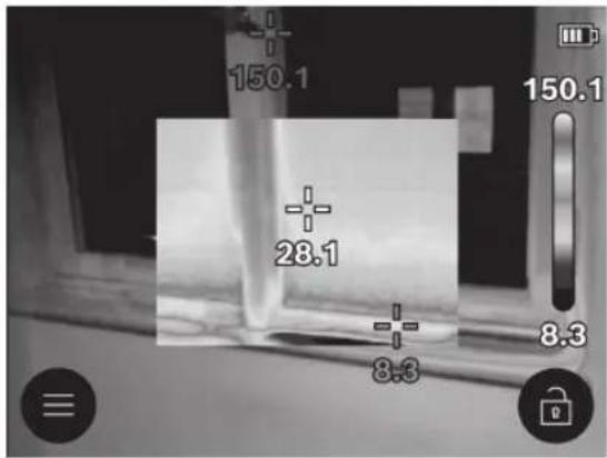
For better orientation (= spatial assignment of the displayed thermal image), a real visual image can be additionally activated when the temperature ranges are balanced.
Note: The overlay of the real image with the thermal image covers a distance of exactly 1 m. If the distances to the object to be measured differ, a shift between the real image and the thermal image occurs due to the operating principle. This shift can be compensated with the special Bosch applications. For information on applications and their compatibility, visit the product page of the measuring device or the website www.bosch-professional.com/thermal.
The measuring device offers you the following options:
- 100% infrared image
Only the thermal image is displayed.

transparent
The displayed thermal image is placed transparently over the real image. This allows objects to be detected better.
To activate/deactivate the setting, access the left sidebar, then scroll to the menu item / .
Confirm the selection by pressing the multifunction button (17) in the center.
- Picture-in-picture
The displayed thermal image is cropped, and the surrounding area is shown as a real image. This setting improves the local assignment of the measurement area.
To activate/deactivate the setting, access the left
sidebar, then scroll to the menu item / .
Confirm the selection by pressing the multifunction button (17) in the center.
Adapting the color representation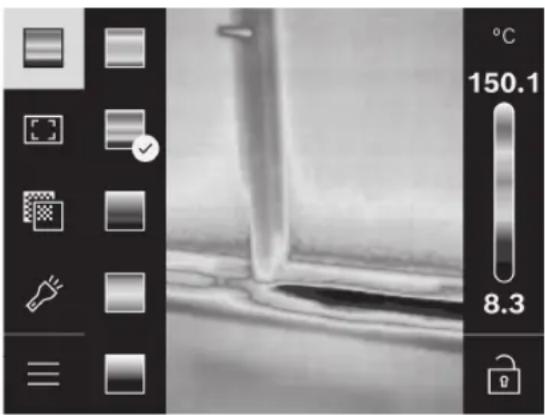
Depending on the measurement situation, different color palettes can facilitate the analysis of the thermal image and illustrate objects or states more clearly on the display. This does not influence the measured temperatures. Only the rendering of temperature values is changed.
To change the color palette, access the sidebar, then scroll to the menu item "Color palette". Confirm the selection by pressing the multifunction button (17) in the center.
Fixing the scale
The color distribution in the thermal image is adjusted automatically, but can be fixed by pressing the multifunction button (17) to the right, and then in the center. This allows comparison of thermal images recorded under different temperature conditions (for example, when checking multiple rooms for thermal bridges) or hiding an extremely cold or hot object in the thermal image, which would otherwise distort it (for example, a radiator as a hot object when detecting thermal bridges).
To switch the scale back to automatic mode, access the sidebar on the right, then press the multifunction button (17) in the center. The temperatures now behave dynamically again and adapt to the measured minimum and maximum values.
Main menu
Access the sidebar on the left (see "Navigating the various menus", Page 245). To access the main menu, press the multifunction button (17) in the center.
- Through this menu item you can delete individual saved images or delete them all at once.
-
- (a)
For some of the most frequently used materials, stored emissivities can be selected. To facilitate the search, the values are grouped in the emissivity catalog. Select the appropriate category from the menu item and then the corresponding material. If you know the emissivity of your measuring object precisely, you can set it as a numerical value in the menu item.
- (b)
Setting this parameter can improve the measurement result, especially for materials with low emissivity (= higher reflection). In some situations (especially indoors), the reflected temperature coincides with the ambient temperature. If objects with very different temperatures near highly reflective objects can influence the measurement, you should adapt this value. To do this, press the multifunction button (17) to the left or right.
-
To ensure high accuracy over the entire measuring range, measurements are taken in 2 temperature ranges. In the measuring function, the measuring device automatically selects the appropriate temperature range based on the temperature distribution in the thermal image. Thus, the number of measured values exceeding a certain temperature threshold is evaluated. If small but hot objects are to be measured, the low temperature range, which is unsuitable for high temperatures, may be selected. This can be identified by the preset symbol \~ on the temperature indicator. In this case, switch to the measuring function <100 °C ... 450 °C> or <-20 °C ... 100 °C>, in which the color distribution corresponds to the set temperature range. The setting is marked on the scale with an upward or downward arrow.
-
- (m): /
The point is displayed in the center of the thermal image and indicates the temperature value measured at that point.
- (n): /
The hottest spot (= measuring pixel) is marked with a red reticle cross in the thermal image. This makes it easier to detect critical points (e.g., loose contact terminals in the control panel).
- (I): /
The coldest spot (= measuring pixel) is marked with a blue reticle cross in the thermal image. This makes it easier to detect critical points (e.g., unsealed areas at the window level).
- (i): /
- (c): /
The average temperature (c) is displayed at the top left in the thermal image (the average temperature of all
248 | English
measured values in the thermal image). This can help determine the reflected temperature.
-
- Through this menu item, you can adjust the brightness of the display lighting system.
- Through this menu item, you can select the time interval for the automatic shutdown of the work lamp when no button is pressed.
- In this menu item, you can choose the time interval after which the measuring device will automatically shut down if no button is pressed. You can also disable the automatic shutdown by selecting the setting .
- In addition to setting the time and date, in this submenu you can also modify their respective formats.
- From this menu item, you can select the display language.
- In this menu item, you can reset the measuring tool to the default settings and permanently delete all data. In certain circumstances, this may take a few minutes. Press the multifunction button (17) to the right to delete all files, or press the multifunction button (17) to the left to cancel the process.
-
In this menu item, you can access information via the measuring tool. There you will find the serial number of the measuring tool and the installed software version. You can also find additional information about the measuring tool, as well as about software updates.
To exit any menu and return to the standard display screen, you can also press the measurement button (6).
Software update for the measuring tool
If necessary, you can update the software of the measuring tool via the USB Type-C® interface. For information on this, visit: www.bosch-professional.com/thermal-update.
Documenting measurement results
Saving measurement results
Immediately after switching on, the measuring tool starts measuring and continues to measure until it is switched off. To save an image, point the camera at the desired measuring object and then press the measurement button (6). The image is saved in the internal memory of the measuring tool. Measurement is interrupted and the image is displayed on the screen. This allows you to view the image carefully and make subsequent adjustments (e.g., color palette).
If you do not want to save the frozen image, start the measurement mode again with the measurement button (6). If you want to save the image in the internal memory of the measuring tool, press the multifunction button (17) in the center.
Accessing saved images
To access the saved thermal images, proceed as follows:
- Immediately after saving, press the multifunction button (17) in the center again. The preview image of the last saved photo will now appear on the display.
- Alternatively, you can access the saved photos in the menu item .
- To switch between the saved thermal images, press the multifunction button (17) to the right or to the left.
In addition to the thermal image, the visual image was also saved. To access it, press the multifunction button (17) up or down.
After 5 seconds, the measuring tool switches to the full screen. On the full screen, the title bar display disappears so that you can view all the details of the thermal image.
By pressing the multifunction button (17) up and down, you can switch between views.
Deleting saved images
To delete one or all thermal images, press the multifunction button (17) in the center. A submenu opens.
- Here you can select whether you want to delete only this image or all images. Confirm the selection by pressing the multifunction button (17) in the center. When selecting <Delete all images>, you can choose between <Delete all> and . Confirm the selection by pressing the multifunction button (17) in the center. – In this submenu, you can also view information regarding emissivity and reflected temperature.
The data fragments of the images remain in memory and can be reconstructed. To delete permanently, select from the main menu → .
Data transfer
Data transfer via the USB interface
Open the cover (11) of the USB Type-C® port.
Connect the USB Type-C® port (12) of the measuring tool to the computer using the USB Type-C® cable (16) from the delivery package.
Now turn on the measuring tool using the power button (18).
Open the file browser on the computer and select the storage device GTC_450. The saved files can be copied from the internal memory of the measuring tool, moved to the computer, or deleted.
As soon as you have completed the desired process, disconnect the storage device from the computer and turn off the measuring tool again using the power button (18).
Caution: Always disconnect the storage device from the operating system first (eject the storage device), otherwise the internal memory of the measuring tool may be damaged.
Remove the USB Type-C® cable and close the cover (11).
Always keep the USB interface cover closed to prevent dust or water splashes from entering the housing.
Note: Connect the measuring tool via USB only to a computer. If it is connected to other devices, the measuring tool may be damaged.
Note: The USB Type-C® interface is used exclusively for data transfer. Batteries and rechargeable batteries cannot be charged through it.
Further processing of thermal images
Saved thermal images can be edited later with special Bosch applications. For information on applications and their compatibility, visit the product page of the measuring tool or the website www.bosch-professional.com/thermal.
Faults – Causes and remedies
In the event of a fault, the measuring tool restarts and can then be used again. Otherwise, refer to the overview below for permanent error messages.
Fault Cause Remedy
| Aparatul de măsură nu poate fi conectat. | Acumulator/Baterii descărcat/e | Încarcă acumulatorul, respectiv înlocuiește bateriile. |
 | Eroare privind acumulatorul/bateriile | Înlocuiti acumulatorul, respectiv bateriile. |
 | Acumulatorul/Bateriile este/sunt prea cald/e sau prea rece/reci | Lasă acumulatorul să se stabilizeze sau înlocuiește acumulatorul sau bateriile. |
 | Aparatul de măsură este prea cald, respectiv prea rece | Lasă aparatul de măsură să se stabilizeze. |
 | Port USB sau cablu USB defect | Verifică dacă aparatul de măsură poate fi conectat la un alt calculator. Dacă nu, trimite aparatul de măsură la un centru de service Bosch autorizat. |
| Aparatul de măsură nu poate fi conectat la un calculator. | Observație: Utilizează întotdeauna cablul USB din pachetul de livrare. | |
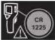 | Baterie rotundă descărcată Înlocuiește bateria rotundă (vezi „Înlocuirea bateriei rotunde (consultă imaginea C)“, Pagina 250). Confirmă înlocuirea cu „OK”, apăsând butonul multifuncțional (17) în centru. | |
| Explicarea termenilorPentru informații suplimentare, accesează www.bosch-professional.com/thermal.Radiația termică infraroșieRadiația termică infraroșie este radiația electromagnetică emisă de fiecare corp la o temperatură de peste 0 Kelvin (-273°C). Cantitatea de radiație depinde de temperatura și de emisivitatea corpului.Gradul de emisiiGradul de emisii al unui obiect depinde de material și de structura suprafeței acestuia. Acesta indică cantitatea de radiație termică infraroșie pe care o emite obiectul comparativ cu un radiator termic ideal (corp negru, grad de | emisii € = 1) și este, în mod corespunzător, o valoare cuprinsă între 0 și 1.Puntea termicăPuntea termică este un loc de pe peretele exterior al unei clădiri în care, din cauza construcției, are loc o pierdere de căldură crescută la nivel local.Punțile termice pot duce la un risc crescut de formare a mucegaiului.Temperatura reflectată/Reflectivitatea unui obiectTemperatura reflectată este radiația termică care nu provine de la obiectul în sine. În funcție de structură și de material, radiațiile ambientale se reflectă în obiectul care urmează să fie măsurat, denaturând, astfel, rezultatul real al temperaturii. | |
Explanation of terms
Infrared thermal radiation
Emissivity
Thermal bridge
Reflected temperature/Reflectivity of an object
Reflected temperature is the thermal radiation that does not originate from the object itself. Depending on the structure and material, ambient radiation is reflected in the object to be measured, thus distorting the actual temperature result.
250 | Romanian
Distance from object
The distance between the object being measured and the measuring device influences the recorded size of the surface per pixel. As the distance from the object increases, you can record larger objects.
| Depărtare (m) Dimensiunea pixelilor pentru infraroșu (mm) | Lățimea × înălțimea domeniului radiațiilor infraroșii (m) |
| 0,30 1,14 ~ 0,29 × 0,22 | |
| 0,55 2,08 ~ 0,53 × 0,40 | |
| 1,00 3,79 ~ 0,97 × 0,73 | |
| 2,00 7,58 ~ 1,94 × 1,46 | |
| 5,00 18,95 ~ 4,85 × 3,64 |
Maintenance and service
Maintenance and cleaning
Store and transport the measuring device only in a suitable container, such as the original packaging.
Always keep the measuring device clean. A dirty infrared receiving lens (5) can affect measurement accuracy.
During cleaning, liquids must not enter the interior of the measuring device.
Do not attempt to remove dirt from the infrared sensor (5), camera (3), work light (4), or laser outlet (2) with sharp objects. Do not wipe the infrared sensor and camera (risk of scratching).
Regularly clean especially the surfaces around the laser outlet and make sure to remove lint.
If you wish to recalibrate the measuring device, contact an authorized Bosch service center.
For repairs, send the measuring device in its original packaging.
There are no user-serviceable parts inside the measuring device. Opening the housing cover can destroy the measuring device.
Replacing the round battery (see image C)
Open the cover (11).
Unscrew the screw (10) from the round battery holder. Remove the round battery holder (9) from the measuring tool. Replace the round battery. Screw the screw (10) back on firmly after installing the round battery holder.
After-sales service and customer advice
Our after-sales service answers your questions regarding the maintenance and repair of your product, as well as spare parts. Exploded views and information on spare parts can also be found at: www.bosch-pt.com The Bosch customer advice team will be happy to answer your questions about our products and their accessories. In case of complaints and spare parts orders, please always indicate the 10-digit identification number according to the type plate of the product.
Romania
Robert Bosch SRL
PT/MKV1-EA
Power tool service
Strada Horia Măcelariu Nr. 30–34, sector 1
013937 Bucharest
Tel.: +40 21 405 7541
Fax: +40 21 233 1313
E-Mail: BoschServiceCenter@ro.bosch.com
www.bosch-pt.ro
You can find other service addresses at:
www.bosch-pt.com/serviceaddresses
Transport
The recommended Li-Ion batteries comply with the requirements of the legislation on the transport of dangerous goods. The batteries can be transported by road by the user without restrictions.
In the case of dispatch by third parties (e.g., air transport or freight forwarder), the special requirements regarding packaging and marking must be observed. In this case, an expert in the field of dangerous goods must be consulted when preparing the package.
Only dispatch the batteries if they have an intact casing. Cover open contacts with adhesive tape and pack the batteries in such a way that they cannot move inside the packaging. Also observe any other national regulations in this area.
Disposal

Measuring instruments, batteries/accumulators, accessories, and packaging must be handed over to a recycling center.
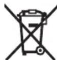
Do not dispose of measuring instruments and batteries in household waste!
Only for EU member states:
Defective or worn-out measuring instruments and batteries/accumulators must be disposed of separately. For this purpose, use the specially provided collection systems.
In the case of improper disposal as waste, used electrical and electronic products can have harmful effects on the environment and human health due to the possible presence of hazardous materials.
Batteries/accumulators:
Li-Ion:
Please observe the instructions in the Transport section (see "Transport", Page 250).

To work with the measuring tool safely and reliably, you must read and follow all instructions. If the measuring tool is not used in accordance with these instructions, the protective mechanisms built into it may be damaged. Never leave the warning labels on the measuring tool illegible. CAREFULLY STORE THESE INSTRUCTIONS AND PASS THEM ON WITH THE MEASURING TOOL.
▶ Caution – if equipment other than that specified here is used for control or calibration, or if other procedures are performed, this may result in dangerous exposure to radiation. ▶ The measuring tool is supplied with a laser warning label (shown in the figure on the graphics page). ▶ If the text on the laser warning label is not in your language, affix the supplied sticker in your language over it before first use.
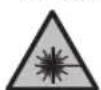
Do not point the laser beam at people or animals and take care not to look directly into the laser beam or its reflection. This can blind people, cause accidents at work, or lead to eye damage.
▶ If the laser beam hits your eyes, close your eyes as quickly as possible and move your head out of the beam. ▶ Do not make any modifications to the laser equipment.
▶ Do not use the laser goggles (accessory) as protective goggles. Laser goggles are used to better recognize the laser beam; they do not protect against laser radiation.
▶ Do not use the laser goggles (accessory) as sunglasses or while driving. Laser goggles do not provide full UV protection and reduce color perception.
Have the measuring tool repaired only by qualified technicians and only with original spare parts. This ensures that the safety functions of the measuring tool are maintained.
▶ Do not allow children to work with the measuring tool without direct supervision. They may inadvertently blind others or themselves.
▶ Do not operate the measuring tool in environments with an increased risk of explosion, where there are easily flammable liquids, gases, or dusts.
Sparks may be generated in the measuring tool that could ignite the dust or vapors.
▶ Do not modify or open the battery. There is a risk of short circuit.
▶ If the battery is damaged or used improperly, vapors may be released. The battery may catch fire or explode. Ensure good ventilation and consult a doctor if you experience any symptoms. The vapors may irritate the respiratory tract.
▶ If used improperly or if the battery is damaged, electrolyte may leak. Avoid contact with it. If electrolyte comes into contact with your skin, rinse the area thoroughly with water. If electrolyte gets into your eyes, seek medical help immediately. Electrolyte can cause skin burns.
The battery can be damaged by sharp objects, e.g. nails or screwdrivers, or by strong impacts. This can cause an internal short circuit and the battery can catch fire, smoke, explode, or overheat.
Protect unused batteries from contact with large or small metal objects, e.g. paper clips, coins, keys, nails, screws, etc., as they can cause a short circuit. The consequences of a short circuit can be burns or fire.
Use the battery only in products from the manufacturer. Only then is it protected against dangerous overload.
Charge batteries only with chargers recommended by the manufacturer. When using chargers for charging unsuitable batteries, there is a risk of fire.

Protect the battery from high temperatures, e.g. from prolonged exposure to direct sunlight, fire, dirt, water, and moisture. There is a risk of explosion and short circuit.
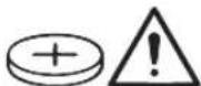
WARNING

Button batteries must not be accessible to children. Button batteries are dangerous.
▶ Button batteries must never be swallowed or inserted into other body openings. If you suspect that a button battery has been swallowed or
inserted into another body opening, seek medical help immediately. Swallowing a button battery can cause severe internal injuries and death within 2 hours.
▶ When replacing the button battery, be careful to perform the operation competently. There is a risk of explosion. ▶ Use only the button batteries specified in this operating manual. Do not use other button batteries or other power sources. ▶ Do not attempt to recharge a button battery and do not short-circuit its terminals. The button battery may leak, explode, ignite, and cause personal injury. Remove and dispose of exhausted button batteries in accordance with regulations. Exhausted button batteries may leak and damage the product or cause personal injury. ▶ Do not overheat button batteries or throw them into fire. The button battery may leak, explode, ignite, and cause personal injury. ▶ Be careful not to damage the button battery and do not attempt to disassemble it. The button battery may leak, explode, ignite, and cause personal injury. ▶ Do not allow a damaged button battery to come into contact with water. When leaking lithium reacts with water, hydrogen may be released, which can lead to fire, explosion, or personal injury. ▶ Stop using the measuring tool if the button battery holder no longer closes properly and completely, remove the button battery and have the measuring tool repaired. ▶ High temperature differences in the thermogram can cause even high temperatures to be displayed in a color associated with low temperatures. Contact with such a surface can lead to burns. Correct temperature measurements are only possible if the set emission coefficient corresponds to the emission coefficient of the object. Objects may be displayed with too high or too low temperatures, which can lead to danger upon contact. ▶ Do not point the measuring device directly at the sun or at a powerful CO2 laser. This can damage the detector. ▶ Protect the measuring device, especially the camera areas and the infrared lens, from moisture, snow, dust, and dirt. The receiving lens may fog up or become dirty, and measurement results may be incorrect. Incorrect device settings, as well as additional atmospheric influences, can
lead to incorrect measurements. Objects may be displayed with too high or too low temperatures, which can lead to danger upon contact.
Product Description and Operation
Please take note of the figures at the beginning of the operating manual.
Intended Use
This thermal imaging camera is intended for non-contact measurement of surface temperatures.
The displayed thermogram shows the temperature distribution of the camera's field of view and thus allows temperature deviations to be presented in a color-differentiated manner.
Thus, when used correctly, surfaces and objects can be inspected contactlessly for temperature differences, i.e., temperature anomalies, and details and/or potential weak points can be visualized, for example:
– thermal insulation and insulation (e.g., detection of thermal bridges),
– active heating and hot water pipes (e.g., underfloor heating) in floors and walls,
– overheated electrical components (e.g., fuses or terminals),
– defective or damaged machine parts (e.g., overheating due to defective ball bearings).
The measuring tool is not suitable for measuring the temperature of gases.
The measuring tool must not be used for human medical purposes.
Please inform yourself about the veterinary medical application at
www.bosch-professional.com/thermal.
The measuring tool is suitable for outdoor and indoor use.
This product is a consumer laser product in accordance with EN 50689.
The light of this measuring tool is intended to illuminate the direct working area of the measuring tool for taking pictures and is not intended for continuous lighting.
The laser point must not be used as a laser pointer. It serves only to mark the measuring surface.
Displayed elements
The numbering of the elements refers to the illustration of the measuring tool on the page with figures.
(1) Protective cap (2) Outlet for the laser beam (3) Visual camera (4) Work light
(5) Infrared sensor (6) Measurement pause/start button (7) Battery compartment (8) Laser warning label (9) Button battery holder clip (10) Button battery holder clip screw (11) Cover for USB socket and button battery holder (12) USB Type-C® socket a) (13) Laser button (14) Battery/adapter release button (15) Rechargeable battery b) (16) USB Type-C® cable b) (17) Multifunction button (18) Trigger switch/Back button (19) Display (20) Serial number (21) Battery adapter insert (22) Batteries b)
(23) Battery adapter cover a) USB Type-C® and USB-C® are trademarks of USB Implementers Forum. b) Additional accessories shown in the figures or described in the operating manual are not included in the scope of delivery.
Indication elements
(a) Emissivity symbol (b) Reflected temperature indicator (c) Average temperature indicator (d) Memory full symbol (e) Work light symbol (f) Laser symbol (g) Battery charge level indicator (h) Maximum surface temperature indicator in the measuring range
(i) Scale (j) Minimum surface temperature indicator in the measuring range
(k) Temperature scale lock symbol
(l) Cold spot indicator (example)
(m) Crosshair with temperature indicator
(n) Hot spot indicator (example)
(o) Menu symbol
Technical data
| Камера за термограми GTC 12V-450-13 | |
| Каталожен номер | 3 601 K83 900 |
| Резолюция инфрачервен сензор 256 × 192 px | |
| Термична чувствителност A) | ≤ 50 mK |
| Спектрален диапазон 8–14 μm | |
| Зрително поле (FOV) A) | 55,6° × 42° |
| Пространствена резолюция (IFOV) 3,79 mrad | |
| Фокусно разстояние A) | ≥ 0,5 m |
| Фокус фиксиран | |
| Стойност на възпроизвеждане образ термограма ≤ 9 Hz | |
| Диапазон измерване повърхностна температура A) | -20 ... +450 °C |
| Точност на измерване повърхностна температура A)B)C | |
| >0 °C ... ≤ +100 °C D) | ±2 °C |
| >+100 °C E) | ±2 % |
| Температурна разделителна способност 0,1 °C | |
| Тип дисплей TFT | |
| Големина на дисплея 2,8" | |
| Резолюция дисплей 480 × 360 px | |
| Разделителна способност интегрирана визуална камера 2 MP (640 × 480 px) | |
| Формат на картината .jpg | |
254 | English
Thermal imaging camera GTC 12V-450-13
| Запаметени елементи на процес на запаметяване 1 × термограма (екранна снимка),1 × визуална реална снимка, вкл. температурни стойности(метаданни) | |
| Макс. брой снимки във вградената памет 500 | |
| Макс. работна височина над базовата височина 2000 m | |
| Степен на замърсяване съгласно IEC 61010-1 2 | F) |
| Относителна влажност на въздуха макс. A) | 90 % |
| Клас лазер 2 | |
| Тип лазер < 1 mW, 645–660 nm | |
| Отклонение на лазерния лъч 1,5 mrad (пъленъгъл) | |
| Електрическо захранване | |
| – Акумулаторна батерия (литиево-йонна) 12 V | |
| – Акумулаторни батерии (алкално-манганови с адаптер за батерии) | 4 × 1,5 V LR6 (AA) |
| – Акумулаторни батерии (NiMH с адаптер за батерии) 4 × 1,2 V HR6 (AA) | |
| Продължителност на работа G) | |
| – Акумулаторна батерия (литиево-йонна) H) | 8 h |
| – Батерии (алкално-манганови) 4 h | |
| Захранване с енергия системно време CR1225 (3-V литиева батерия) | |
| USB-Standard 2.0 | |
| USB интерфейс USB Type-C® | |
| Тегло J) | 0,354 kg |
| Размери (дължина × ширина × височина) K) | 89 × 79 × 209 mm |
| Клас на защита (с изключение на акумулаторната батерия/батериите, в изправена позиция) | IP54 |
| Препоръчителна температура на околната среда при зареждане | 0 °C ... +35 °C |
| Разрешени температури на околната среда | |
| – по време на работа –10 °C ... +50 °C | |
| – при складиране с акумулаторна батерия | –20 °C ... +50 °C |
| – при складиране без акумулаторна батерия | –20 °C ... +70 °C |
| Препоръчителни акумулаторни батерии | GBA 12V... |
| Препоръчителни зарядни устройства | GAL 12...GAX 18... |
A) according to VDI 5585 standard (average value)
B) At ambient temperatures of 20–23 °C and an emissivity coefficient of > 0.95, measuring distance: 1 m, operating time: > 5 min, aperture of 150 mm, with work light and laser switched off.
C) With deviation switched on according to use (e.g., reflection, distance, ambient temperature).
D) Applies to the center point; for all other pixels, add ±1 °C.
E) Applies to the center point; for all other pixels, add ±1 %.
F) Only non-conductive contamination, but temporary conductivity due to condensation may be expected.
G) With work light switched off and medium display brightness.
H) Depending on the rechargeable battery used.
I) At ambient temperatures of 20-30 °C.
J) Weight without rechargeable battery/adapter/batteries.
K) With GBA 12V 2.0Ah or battery adapter.
The serial number (20) on the rating plate serves to uniquely identify your measuring tool.
Power supply for the measuring tool
The measuring tool can be powered by a Bosch lithium-ion rechargeable battery, by standard batteries, or by standard NiMH rechargeable batteries.
Working with the rechargeable battery (see figure A)
▶ Use only the chargers specified in the Technical Data section. Only these chargers have parameters suitable for the lithium-ion battery used in your measuring tool.
Note: Lithium-ion rechargeable batteries are supplied partially charged due to international transport regulations. To ensure the full capacity of the battery, charge it completely before first use.
To insert the charged battery (15), push it into the battery mount (7) until you feel a distinct click.
To remove the battery (15), press the release buttons (14) and pull the battery out of the battery mount (7). Do not use force.
Working with batteries (see figure B)
For the operation of the measuring tool, the use of alkaline-manganese or NiMH rechargeable batteries is recommended.
The batteries are inserted into the battery adapter.
The battery adapter is intended only for use with the designated Bosch measuring tools; its use with power tools is not permitted.
To insert the batteries, push the battery adapter housing (21) into the battery mount (7). Insert the batteries as shown on the image on the closing lid (23) in the housing. Place the closing lid on the housing until you feel a distinct click. To remove the batteries (22), press the release buttons (14) on the lid (23) and pull it off. Remove the batteries. To remove the insert (21) located inside the battery housing, grasp it from the inside and pull it out of the measuring tool with a slight push toward the side wall.
Always replace all batteries or rechargeable batteries at the same time. Use only batteries or rechargeable batteries from one manufacturer and with the same capacity.
When you do not use the measuring tool for an extended period, remove the batteries or rechargeable batteries. Batteries and rechargeable batteries can corrode if stored in the measuring tool for a longer time.
Instructions for optimal handling of the rechargeable battery
Protect the rechargeable battery from moisture and water.
Store the rechargeable battery only in the temperature range from –20 °C to 50 °C. For example, do not leave the rechargeable battery in a car in the sun during summer.
A significantly shortened operating time after charging indicates that the rechargeable battery is worn out and must be replaced.
Follow the disposal instructions.
Work
▶ Protect the measuring tool from moisture and direct sunlight. ▶ Do not expose the measuring tool to extreme temperatures or sudden changes in temperature. For example, do not leave it in a car for a long time. In case of large temperature differences, allow the power tool to acclimate before switching it on. In extreme temperatures or with large temperature differences, the accuracy of the measuring tool may deteriorate. ▶ Allow the measuring tool to acclimate well. In case of large temperature differences, the acclimatization time can be up to 60 minutes. This can happen, for example, if the measuring tool was stored in a cold car and then a measurement is taken in a warm building. ▶ Avoid strong impacts or dropping the measuring tool. After strong external impacts and in case of malfunction, you must send the measuring tool to an authorized Bosch power tool service center for inspection.
Operation
Initial operation
When switching on the measuring tool for the first time or after resetting to factory settings, some basic settings must be made. Select the desired values by pressing the multifunction button (17) down, up, left, or right. Press the multifunction button (17) in the middle to confirm your selection. When you confirm the selection, the next setting will be shown on the display. The status bar at the top shows the total number and the number of remaining settings.
The following basic settings are available:
- <Language>
- <Date format>
- <Date>
- <Time format>
- <Time>
Switching on and off
For measuring, open the protective cap (1). During operation, make sure that the infrared sensor is not closed or covered.
To switch on the measuring tool, press the on/off switch (18). The initialization sequence appears on the display (19). After the start sequence, the measuring tool immediately begins measuring and continues to do so constantly until it is switched off.
Note: During the first few minutes, the measuring tool may self-level more frequently because the sensor and ambient temperatures have not yet equalized. New sensor leveling allows for precise measurement.
During this time, the temperature indicator is marked with \~. This effect is amplified by strong fluctuations in the ambient temperature. Therefore, if possible, switch on the measuring tool a few minutes before starting the measurement so that it can thermally stabilize.
To switch off the measuring tool, press the trigger switch (18) for > 1 s. The measuring tool saves all settings and then switches off. Close the protective cap (1) for safe transport of the measuring tool.
In the main menu, you can select whether and after how long the measuring tool should switch off automatically (see "Main menu", Page 258).
If the rechargeable battery or the measuring tool is outside the operating temperature specified in the technical data, the measuring tool switches off automatically after a brief warning (see "Errors – Causes and remedies", Page 260). Allow the measuring tool to acclimate to the temperature and then switch it on again.
Navigate in the various menus
Navigate in the various menus of the measuring tool:
– Calling up the menu bars: Press the multifunction button (17) in the middle or on the left. The menu bars on the right and left are shown on the display, with the main menu highlighted. – Scrolling in the left menu bar/navigating in the main menu: Press the multifunction button (17) up, down, left, or right. – Switching between the left or right menu bar: Press the multifunction button (17) left or right. – Confirming the selection/entering a submenu: Press the multifunction button (17) in the middle. – Returning from a submenu to a higher-level menu: Press the Back button (18).
Preparing the measurement
Setting the emission coefficient for surface temperature measurements
The emission coefficient of a body depends on the material and the surface structure. It expresses how much infrared thermal energy an object emits compared to an ideal emitter (black body, emission coefficient € = 1) and therefore has a value between 0 and 1.
To determine the surface temperature, the infrared radiation of the object at which the tool is aimed is measured without contact. For correct measurements, the emission coefficient set on the measuring tool must be checked before each measurement and, if necessary, adapted to the object being measured.
The emission coefficients preset in the measuring tool are reference values.
You can select one of the preset emission coefficients or enter an exact numerical value. Set the desired emission coefficient via the menu <Measurement parameters
> → <Coefficient> (see "Main menu", Page 258).
Correct temperature measurements are only possible if the set emission coefficient corresponds to the emission coefficient of the object.
The lower the emission coefficient, the greater the influence of the reflected temperature on the measurement result. Therefore, when changing the emission coefficient, always adapt the reflected temperature. Set the reflected temperature via the menu <Measurement parameters> → <Reflected temperature> (see "Main menu", page 258).
Temperature differences incorrectly displayed by the measuring device can be due to different temperatures and/or different emission coefficients. With strong differences in emission coefficients, the displayed temperature differences can differ significantly from the real ones.
If several measurement objects made of different materials or with different structures are in the measurement area, the displayed temperature values are only accurate for objects that match the set emission coefficient. For all other objects (with other emission coefficients), the displayed color differences can be used as an indication of the temperature relationships.
Notes on ambient conditions during measurement
Highly reflective or shiny surfaces (e.g., shiny ceramic tiles or metal surfaces) can greatly impair or influence the displayed results. If necessary, stick a dark matte tape with good thermal conductivity onto the measured surface. Wait for some time until the tape has adjusted its temperature to that of the surface.
For reflective surfaces, be careful to work at a suitable angle so that the result is not impaired by reflected thermal radiation from other objects. For example, when measuring from the front perpendicularly, the reflection of heat from your own body heat can interfere with the measurement. On a flat surface, the contours and temperature of your body (reflected value) can be displayed, which does not correspond to the actual temperature of the measured surface (measured value, or real surface value).
Measurement through transparent materials (e.g., glass or transparent plastics) is fundamentally impossible.
The measurement results are more accurate and reliable the better and more stable the conditions under which the measurement is performed. Not only strong temperature fluctuations in the ambient conditions are important, but also strong fluctuations in the temperatures of the measured object can affect accuracy.
Temperature measurement via infrared radiation is influenced by the presence of smoke, steam/high air humidity, or dust in the air.
Notes for better measurement accuracy:
– Get as close as possible to the measurement object to minimize disturbing factors between you and the measured surface. – Before measuring, ventilate the rooms, especially if the air is polluted or saturated with vapors. After ventilation, wait for some time for the temperatures in the room to equalize, so that their usual values are reached.
Marking the measurement point
Do not point the laser beam at people or animals; do not look into the laser beam, even from a distance.
The measuring tool is equipped with a laser to mark the measuring spot.
Press and hold the laser button (13). The laser symbol (f) appears in the status bar and a red circle is shown around the crosshair (m). The laser and crosshair overlap exactly at a distance of 1 m. When the laser button (13) is released, the laser switches off.
Setting temperatures based on the scale
The scale (i) is displayed on the right side of the screen. The values at the top and bottom are oriented to the maximum temperature (h) and minimum temperature (j) determined in the thermogram. 99.99% of all pixels are evaluated for the scale. The assignment of color to temperature values in the image is uniform (linear).
Using different color tones, temperatures can be assigned within these two extreme values. A temperature that is exactly between the maximum and minimum
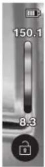
value, for example, is indicated by the middle color range of the scale.
To determine the temperature of a specific area, move the measuring tool so that the crosshair with the temperature indicator (m) is aimed at the desired point or area. In automatic mode, the color spectrum of the scale is always distributed over the entire measuring area within the maximum and minimum temperature (i.e., uniformly).
The measuring tool displays all measured temperatures in the measuring area relative to each other. If, in a given area, for example, in a color representation, heat is shown in blue in the color palette, this means that the blue areas are part of the colder measured values in the current area. However, these areas can be in a temperature range that, under certain circumstances, can lead to injuries. Therefore, always pay attention to the displayed temperatures on the scale or directly on the crosshair.
Functions
Observe the information for navigating the various menus (see "Navigating the various menus", Page 256)

Illuminating the measuring object
The measuring tool is equipped with a work light (4). It is intended to illuminate the direct working area of the measuring tool for taking pictures and is not intended for continuous lighting.
To switch the work light on/off, call up the left sidebar. Scroll to the menu item / and confirm your selection. If the work light is switched on, this is shown in the status bar.
The light automatically switches off after 2 minutes to avoid affecting the accuracy of the measurement.
The automatic switch-off time can be set in the menu under <Tool Settings>.
Overlay of thermal image and real image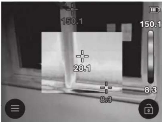
For better orientation (= spatial distribution of the displayed thermal image) in the case of equalized temperature areas, a real image can additionally be displayed.
Note: The overlay of real image and thermal image is accurate at a distance of 1 m. At different distances from the measuring object, a displacement between the real image and the thermal image generally occurs. This displacement must be compensated for with special Bosch applications. Information on the applications and their compatibility can be found on the product page of the measuring tool or at www.bosch-professional.com/thermal.
The measuring tool offers you the following options:
- 100% infrared image
Only the thermal image is displayed.

- Transparency
The displayed thermal image is placed transparently over a real image. This allows objects to be recognized better.
To activate/deactivate the setting, call up the left sidebar and scroll to the menu item <Visual Image not on>/<Visual Image not off>. Confirm your selection by pressing the multifunction button (17) in the middle.

- Picture-in-picture
The displayed thermal image is cropped and the surrounding area is shown as a real image. This setting improves the local assignment of the measuring area.
To activate/deactivate the setting, call up the left sidebar and scroll to the menu item / . Confirm your selection by pressing the multifunction button (17) in the middle.
Adapting the color representation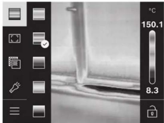
Depending on the measuring situation, different color palettes can facilitate the analysis of the thermal image and show objects and aspects of the display more clearly. The measured temperatures are not affected by this. Only the display of the temperature values changes.
To change the color palette, call up the side bar and navigate to the "Color palette" menu item. Confirm your selection by pressing the multifunction button (17) in the center.

Fixing the scale
The adaptation of the color distribution in the thermogram is automatic, but it can be fixed by pressing the multifunction button (17) to the right and then in the center. This allows comparability of thermograms that are captured under different temperature conditions (e.g., when checking several rooms for thermal bridges) or hiding an extremely cold or hot object in the thermogram that would otherwise distort it (e.g., a heating element as a hot object when searching for thermal bridges).
To switch the scale back to automatic, call up the right side bar and press the multifunction button (17) in the center. The temperatures are now dynamic again and adapt to the measured minimum and maximum values.
Main menu
Call up the left side bar (see "Navigating the menus", page 256). To reach the main menu, press the multifunction button (17) in the center.
- <Gallery> In this menu item you can delete saved images individually or all at once.
- <Measurement parameters>
- <Emissivity> (a)
For some of the most common materials, stored emissivity coefficients are available. To make searching easier, the values are
grouped in the emissivity coefficient catalog. In the <Material catalog> menu item, first select the appropriate category and then the appropriate material. If you know the exact emissivity coefficient of the object you are measuring, you can enter its numerical value in the <User-defined> menu item.
• <Reflected temperature> (b)
Setting this parameter improves the measurement result, especially for materials with low emissivity (= high reflectivity). In some situations (especially indoors), the reflected temperature corresponds to the ambient temperature. If there are objects with significantly different temperatures near highly reflective objects that could affect the measurement, this value should be adjusted. To do this, press the multifunction button (17) to the left or right.
- <Temperature range>
- <Temperature range>
To ensure high accuracy over the entire measuring range, measurement is performed in 2 temperature ranges. In the <Auto> measurement function, the measuring device automatically selects the appropriate temperature range based on the temperature distribution in the thermogram. It evaluates how many measured values are present above a certain temperature threshold. If very small but hot objects are to be measured, a temperature range that is inappropriately low for high temperatures may be selected. This is recognized by the symbol \~ in front of the temperature indication. In such a case, switch to the
measurement function <100 °C ... 450 °C> or <-20 °C ...
100 °C>, in which the color distribution corresponds to the set temperature range. The setting is indicated on the scale with an up or down arrow.
- <Display settings>
• <Center point> (m): <ON>/<OFF>
The point is displayed centrally in the thermogram and shows you the measured temperature value at that location.
• <Hot spot> (n): <ON>/<OFF>
The hottest point (= measuring pixel) is marked with a red cross in the thermogram. This makes it easier to find critical locations (e.g., loose contact terminal in the control cabinet).
• <Cold spot> (I): <ON>/<OFF>
The coldest point (= measuring pixel) is marked with a blue cross in the thermogram. This makes it easier to find critical locations (e.g., unsealed area in the window).
• <Temperature scale> (i): <ON>/<OFF>
• <Average temperature> (c): <ON>/<OFF>
The average temperature (c) is displayed at the top left in the thermogram (average temperature of all measured values in the thermogram). This can help you determine the reflected temperature.
- <Tool settings>
• <Display brightness>
In this menu item you can adjust the brightness of the display lighting.
•
In this menu item you can select the time interval for automatic switch-off of the working light if no button is pressed.
- <Instr. auto off after>
In this menu item you can select the time interval after which the measuring instrument switches off automatically if no button is pressed. You can also deactivate the automatic switch-off by selecting the option <Never>.
«Date and time»
In this submenu you can, in addition to setting the time and date, also change their respective formats.
- <Language>
In this menu item you can select the language used in the display.
- <Factory settings>
In this menu item you can reset the measuring instrument to factory settings and delete all data permanently. This may, under certain circumstances, take several minutes. Press the multifunction button (17) on the right to delete all files or the multifunction button (17) on the left to cancel the process.
- <Information>
In this menu item you can call up information about the measuring instrument. There you can find the serial number of the measuring instrument and the version of the installed software. In addition, you can find further information about the measuring instrument and about the software update.
To leave any menu and return to the main screen, you can also press the Measure button (6).
Updating the software of the measuring instrument
If necessary, you can update the measuring tool's software via the USB Type-C® interface. You will find information on this at: www.bosch-professional.com/thermal-update.
Documenting measurement results
Saving measurement results
Immediately after switching on, the measuring tool starts measuring and continues to do so continuously until it is switched off.
To save an image, point the camera at the desired measuring object and press the measurement button (6). The image is saved in the internal memory of the measuring tool. The measurement is frozen and displayed on the screen. This allows you to examine the image carefully and make subsequent adjustments (e.g., to the color palette). If you do not want to save the frozen image, start
the measurement mode again with the measurement button (6). If you want to store the image in the internal memory of the measuring tool, press the multifunction button (17) in the middle.
Recalling saved images
To recall the saved thermograms, proceed as follows:
– Immediately after saving, press the multifunction button (17) in the middle again. A review of the last saved images is shown on the display. – Alternatively, you can recall the saved images in the <Gallery> menu item. - To switch between the saved thermograms, press the multifunction button (17) to the right or left.
In addition to the thermogram, the visual image is also saved. To recall it, press the multifunction button (17) up or down.
After 5 seconds, the measuring tool switches to full-screen view. In full-screen view, the header bar indicator is hidden so that all details of the thermogram can be examined.
By pressing the multifunction button (17) up and down, you can switch between views.
Deleting saved images
To delete individual or all thermograms, press the multifunction button (17) in the middle. A submenu opens.
– Here you can choose whether you want to delete only this image or all images. Confirm your selection with the multifunction button (17) in the middle. When selecting <Delete>, you can choose between <Delete all> and <Cancel>. Confirm your selection with the multifunction button (17) in the middle.
In this submenu you can also view information about the emissivity coefficient and the reflected temperature.
The data fragments of the images remain in memory and can be reconstructed. For final deletion, select <Tool settings> → <factory settings> in the main menu.
Data transfer
Data transfer via USB interface
Open the cover (11) of the USB Type-C® socket. Connect the USB Type-C® socket (12) of the measuring tool to your computer using the supplied USB Type-C® cable (16).
Now switch on the measuring tool with the on/off switch (18).
Open the file browser on your computer and select the drive GTC_450. The saved files can be copied, moved, or deleted from the internal memory of the measuring tool.
When the desired procedure is complete, safely eject the drive from the computer and switch off the measuring tool again with the on/off switch (18).
Caution: Always eject the drive from your operating system first (safely remove hardware), as otherwise the internal memory of the measuring tool may be damaged.
Remove the USB Type-C® cable and close the cover (11). Always keep the cover of the USB interface closed to prevent dust or water splashes from entering the housing.
Note: Only connect the measuring tool to a computer via USB. Connecting to other devices may damage the measuring tool.
Note: The USB Type-C® interface is only for data transfer. Batteries and rechargeable batteries cannot be charged through it.
Further processing of thermal images
You can further process the saved thermal images with special Bosch applications. Information about the applications and their compatibility can be found on the product page of the measuring tool or at www.bosch-professional.com/thermal.
Errors – Causes and remedies
In case of a malfunction, the measuring tool performs a restart and can then be used again. Otherwise, the following overview will help you with persistent error messages.
Error Cause Remedy
| Измервателният уред не може да се включи. | Акумулаторни/обикновени батерии празни | Заредете акумулаторните батерии, респ. заменете батериите. | |
 | Акумулаторни/обикновени батерии грешка | Заменете акумулаторната батерия, респ. батериите. | |
 | Акумулаторни/обикновени батерии са твърде горещи, респ. твърде студени | Изчакайте акумулаторните батерии да се темперират, респ. заменете ги. | |
Error Cause Remedy
The measuring tool is too hot or too cold. Wait for the measuring tool to reach the ambient temperature.
USB port or USB cable defective. Check whether the measuring tool can be connected to another computer. If it cannot, send the measuring tool to an authorized Bosch customer service center.
The measuring tool cannot be connected to a computer.
Note: Always use the USB cable from the delivery scope.
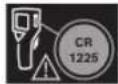
Button battery exhausted. Replace the button battery (see "Replacing the button battery (see Fig. C)", page 261). Confirm the replacement with "OK" by pressing the multifunction button (17) in the middle.
Explanation of terms
Additional information can be found at www.bosch-professional.com/thermal.
Infrared thermal radiation
Infrared thermal radiation consists of electromagnetic rays emitted by any body above 0 Kelvin (-273 °C). The intensity of the rays depends on the temperature and the emissivity of the body.
Emissivity
The emissivity of a body depends on the material and the surface structure. It expresses how much infrared thermal energy the object emits compared to an ideal emitter (black body, emissivity € = 1) and therefore has a value from 0 to 1.
Thermal bridge
A thermal bridge is a location on the exterior wall of a building where, due to the construction, localized increased heat loss occurs.
Thermal bridges can lead to an increased risk of mold.
Reflected temperature/reflectivity of an object
Reflected temperature refers to heat radiation that does not originate from the object itself. Depending on the structure and material, radiation from the surroundings is reflected onto the object being measured, thus distorting the actual temperature result.
Distance to the object
The distance between the measured object and the measuring device influences the detected size of the pixel surface. With increasing distance to the object, you can detect larger objects.
| Разстояние (m) Размер на инфрачервения пиксел (mm) | Ширина × височина инфрачервена зона (m) |
| 0,30 1,14 ~ 0,29 × 0,22 | |
| 0,55 2,08 ~ 0,53 × 0,40 |
| Разстояние (m) Размер на инфрачервения пиксел (mm) | Ширина × височина инфрачервена зона (m) |
| 1,00 3,79 ~ 0,97 × 0,73 | |
| 2,00 7,58 ~ 1,94 × 1,46 | |
| 5,00 18,95 ~ 4,85 × 3,64 |
Maintenance and service
Maintenance and cleaning
Store and transport the measuring device only in the protective pouch included in the scope of delivery.
Always keep the measuring device clean. A dirty infrared sensor (5) can impair measurement accuracy.
Water must not enter the measuring device during cleaning.
Do not attempt to remove dirt from the infrared sensor (5), camera (3), work light (4), or laser outlet (2) with sharp objects. Do not wipe the infrared sensor and camera (risk of scratching).
Regularly clean especially the surfaces of the laser beam outlet and ensure no lint remains.
If you wish to have the measuring device recalibrated, please contact an authorized Bosch service center.
If repair is necessary, send the measuring device in its original packaging.
There are no user-serviceable parts inside the measuring tool. Opening the housing of the measuring tool may damage the tool.
Replacing the button battery (see figure C)
Open the cover (11).
Turn the screw (10) on the button battery holder. Pull the button battery holder (9) out of the measuring tool. Replace the button battery. Tighten the screw (10) again after inserting the button battery holder.
262 | Macedonian
Tighten the screw (10) after inserting the button battery holder.
Customer service and usage consultation
The customer service department answers your questions regarding repairs, maintenance, and spare parts for your tool. Exploded views and information on spare parts can also be found at: www.bosch-pt.com
The Bosch usage consultation team will be happy to help you with any questions about our tools and their accessories.
When making inquiries or ordering spare parts, please always quote the 10-digit material number found on the tool's rating plate.
Bulgaria
Robert Bosch SRL
Service scule electrice
Strada Horia Măcelariu Nr. 30–34, sector 1
013937 Bucureşti, România
Tel.: +359(0)700 13 667 (Bulgarian)
Fax: +40 212 331 313
Email: BoschServiceCenterBG@ro.bosch.com
www.bosch-pt.com/bg/bg/
Additional service addresses can be found at:
www.bosch-pt.com/serviceaddresses
Transport
The recommended lithium-ion batteries are subject to the requirements of dangerous goods legislation. The user can transport the batteries by road without additional conditions.
When shipping from third parties (e.g., air transport or freight forwarding), special requirements for packaging and labeling must be taken into account. For this purpose, consult an expert in the relevant field when preparing the packaging.
Only send batteries if their housing is not damaged. Insulate the contact terminals with insulating tape and pack the battery so that it cannot move in the packaging. Please also observe the requirements of local legislation.
Disposal

With a view to protecting the environment, the measuring device, ordinary or rechargeable batteries, additional accessories, and packaging must be handed over for recycling of the raw materials they contain.
raw materials.
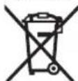
Do not dispose of measuring devices and rechargeable batteries/batteries in household waste!
Only for EU countries:
Unusable measuring instruments and defective or exhausted rechargeable/ordinary batteries must be disposed of separately. Use the designated collection systems.
If disposed of incorrectly, waste electrical and electronic equipment can have harmful effects on the environment and human health due to the potential presence of hazardous substances.
Rechargeable batteries/batteries:
Lithium-ion:
Please follow the instructions in the Transport section (see "Transport", Page 262).
Safety Notes

All instructions must be read and observed in order to work safely and without danger with the measuring tool. If the measuring tool is not
used in accordance with the supplied instructions, the function of the protective mechanisms built into the measuring tool may be impaired. Do not damage the warning labels. KEEP THESE INSTRUCTIONS IN A SAFE PLACE AND HAND THEM OVER WITH THE MEASURING TOOL.
▶ Caution – if you use other devices for adjustment and handling than those specified here or different procedures, this may lead to dangerous exposure to radiation. ▶ The measuring tool is delivered with a laser warning label (marked on the display of the measuring tool on the graphic page). If the text on the laser warning label is not in your language, stick the label in your language over it before the first use.
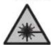
Do not direct the laser beam at people or animals and do not look into the direct or reflected laser beam yourself. This can blind people, cause accidents, or damage your eyes.
If the laser beam reaches your eyes, you should immediately close your eyes and move your head out of the laser beam. ▶ Do not make any modifications to the laser device. ▶ Do not use the laser safety glasses (accessory) as protective goggles. The laser safety glasses are used for better
recognition of the laser beam; however, they do not protect against laser radiation.
▶ Do not use the laser safety goggles (accessory) as sunglasses or in traffic. Laser goggles do not provide full UV protection and reduce color recognition. ▶ The measuring tool may only be repaired by qualified specialist personnel and only with original spare parts. This ensures that the safety of the measuring tool is maintained. ▶ Do not allow children to use the laser measuring tool without supervision. They could blind themselves or other persons. ▶ Do not operate the measuring tool in environments where there is a risk of explosion, or where flammable liquids, gases, or dust are present. The measuring tool creates sparks that may ignite the dust or fumes. ▶ Do not modify or open the battery. There is a risk of short circuit. ▶ If the battery is damaged or used improperly, fumes may escape. The battery may catch fire or explode. Provide fresh air and seek medical attention if you have been affected. The fumes may irritate the respiratory tract. ▶ If the battery is used incorrectly or is damaged, flammable liquid may leak from the battery. Avoid contact with it. If you accidentally come into contact with the liquid, rinse with water. If the liquid comes into contact with your eyes, seek medical help. Leaked battery fluid may cause skin irritation or burns. ▶ The battery can be damaged by sharp objects such as nails or screwdrivers, or by external impact. This may cause an internal short circuit, and the battery may catch fire, emit smoke, explode, or overheat. Keep the unused battery away from paper clips, keys, coins, nails, screws, or other small metal objects that could bridge the contacts. A short circuit between the battery contacts may cause burns or fire. ▶ Use the battery only in products from the manufacturer. This is the only way to protect the battery from dangerous overload. ▶ Charge the batteries only with chargers recommended by the manufacturer. If a charger intended for a specific type of battery is used with other batteries, there is a risk of fire.

Protect the battery from heat, e.g., from prolonged exposure to sunlight, fire, dirt, water, and moisture.
Otherwise, there is a risk of explosion and short circuit.
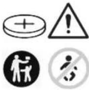
WARNING
Ensure that children do not come into contact with the button cell battery. Button cell batteries are dangerous.
Never swallow button batteries or insert them into other body orifices. If you suspect that a button battery has been swallowed or inserted into another part of the body, seek medical attention immediately. Swallowing a button battery can cause severe internal burns or death within 2 hours. ▶ When replacing the button battery, check that it is correctly inserted. Otherwise, there is a risk of explosion. ▶ Use only the button batteries specified in these operating instructions. Do not use other button batteries or other power supplies. Do not attempt to recharge the button battery and do not short-circuit it. The button battery may leak, explode, catch fire, and cause injury. ▶ Properly dispose of and discard depleted button batteries. Depleted button batteries may leak and thereby damage the product or cause injury. Do not overheat the button battery and do not throw it into a fire. The button battery may leak, explode, catch fire, and cause injury. Do not damage the button battery or disassemble it. The button battery may leak, explode, catch fire, and cause injury. Do not expose the button battery to water. Leaking lithium can react with water to produce hydrogen, which can lead to fire, explosion, or personal injury. ▶ Do not use the measuring device any longer if the button battery compartment cannot be closed properly and completely; remove the button battery and have the measuring device repaired. ▶ Large temperature differences in the thermal image can cause high temperatures to be displayed in a color associated with low temperatures. Contact with such a surface can lead to burns. ▶ Accurate temperature measurements are possible only if the emissivity and the emissivity of the object match. Objects may be displayed at too high or too low a temperature, which can lead to danger upon contact.
▶ Do not point the measuring device directly at the sun or at a high-performance CO₂ laser. This can damage the detector.
▶ Protect the measuring device, especially the camera area and the infrared lens, from moisture, snow, dust, and dirt. The receiving lens may fog up or become dirty and produce incorrect measurement results. Incorrect device settings as well as additional atmospheric influencing factors can lead to incorrect measurements. Objects may be displayed at too high or too low a temperature, which can lead to danger upon contact.
Product description and performance
See the illustrations at the front of the operating instructions.
Intended use
This thermal camera is intended for non-contact measurement of surface temperatures.
The displayed thermal image shows the temperature distribution of the visible field of the thermal camera, thereby allowing temperature deviations to be displayed in different colors.
In this way, with proper use, temperature differences or abnormalities on surfaces and objects can be searched for, making components and/or weak points visible, e.g.:
– thermal and conventional insulation (e.g., detection of thermal bridges), – active heating and hot water pipes (e.g., underfloor heating) in floors and walls, – overheated electrical components (e.g., fuses or terminals), – defective or damaged machine parts (e.g., overheating due to faulty ball bearings).
The measuring device is not suitable for measuring gas temperatures.
The measuring device must not be used for human medical purposes.
For information on veterinary use, visit www.bosch-professional.com/thermal.
The measuring device is suitable for indoor and outdoor use.
This product is a consumer laser product in accordance with EN 50689.
The light of this measuring device is intended to illuminate the direct working area of the measuring device for capturing images and does not serve as a permanent work light.
The laser point must not be used as a laser pointer. It is used exclusively to mark the measuring surface.
Illustration of components
The numbering of the component images refers to the display of the measuring device on the graphic page.
(1) Protective cap (2) Laser beam outlet opening (3) Visual camera (4) Work light (5) Infrared sensor (6) Measurement button Pause/Start (7) Battery compartment (8) Laser warning label (9) Button cell holder
(10) Button cell holder with screw
(11) USB connector cap and button cell holder
(12) USB Type-C® port a)
(13) Laser button
(14) Battery/battery adapter unlock button
(15) Battery b)
(16) USB Type-C® cable b)
(17) Multifunction button
(18) On/off button/back button
(19) Display
(20) Serial number
(21) Battery adapter cover
(22) Batteries b)
(23) Battery adapter closing cap
a) USB Type-C® and USB-C® are trademarks of USB Implementers Forum.
b) The described equipment shown in the images is not part of the standard delivery scope.
Display elements
(a) Emission level display (b) Reflected temperature display (c) Average temperature display (d) Full memory indicator (e) Work light indicator (f) Laser indicator (g) Charge status display (h) Maximum temperature display of the measuring area surface (i) Scale (j) Minimum temperature display of the measuring area surface (k) Temperature scale lock indicator (l) Cold spot indicator (example) (m) Temperature display marker
(n) Hot spot indicator (example)
(o) Menu indicator
Technical data
| Термална камера GTC 12V-450-13 | |
| Број на дел | 3 601 K83 900 |
| Резолуција на инфрацрвениот сензор 256 × 192 px | |
| термичка чувствителностA) | ≤ 50 mK |
| Спектрален опсег 8–14 μm | |
| Видливо поле (FOV)A) | 55,6° × 42° |
| Просторна резолуција (IFOV) 3,79 mrad | |
| Оддалеченост на фокусотA) | ≥ 0,5 m |
| Фокус фиксен | |
| Брзина на повторно прикажување на термалната слика ≤ 9 Hz | |
| Мерно подраче на температурата на површинатаA) | -20 ... +450 °C |
| Прецизност на мерењето на температурата на површинатаA)(B)(C) | ±2 °C |
| >0 °C ... ≤ +100 °CD) | ±2 % |
| >+100 °CE) | |
| Резолуција на температурата 0,1 °C | |
| Тип на екран TFT | |
| Големина на екранот 2,8" | |
| Резолуција на екранот 480 × 360 px | |
| Резолуција на интегрираната визуелна камера 2 MP (640 × 480 px) | |
| Формат на слика .jpg | |
| Зачувани елементи по постапка на зачувување 1 × термална слика (слика од екранот),1 × визуелна реална слика вкл. температурни вредности (метаподатоци) | |
| Макс. број на слики во внатрешната меморија на слики 500 | |
| Макс. оперативна висина преку референтната висина 2000 m | |
| Степен на извалканост според IEC 61010-1 2 | г) |
| Релативна влажност на воздухот макс.A) | 90 % |
| Класа на ласер | 2 |
| Тип на ласер | < 1 mW, 645–660 nm |
| Отстапување на ласерскиот зрак | 1,5 mrad (целосен агол) |
| Напојување со енергија | |
| – Акумулаторски батерии (литиум-јонски) | 12 V |
| – Батерии (алкално-мангански со батериски адаптер) | 4 × 1,5 V LR6 (AA) |
| – Акумулаторски батерии (NiMH со батериски адаптер) | 4 × 1,2 V HR6 (AA) |
| Времетраење на режимG) | |
| – Акумулаторски батерии (литиум-јонски)H) | 8 h |
| – Батерии (алкални-мангански) | 4 h |
| Системско време за напојување со енергија | CR1225 (3-V-литиумска батерија) |
| USB-стандарден | 2.0 |
| USB-интерфејс | USB Type-C® |
| ТежинаJ) | 0,354 kg |
| Димензии (должина × ширина × висина)K) | 89 × 79 × 209 mm |
Thermal camera GTC 12V-450-13
| Вид на заштита (извадена акумулаторска батерија/батерија, во исправена позиција) | IP54 |
| Препорачана околна температура при полнење 0 °C ... +35 °C | |
| Дозволена околна температура | |
| – при режим на работа –10 °C ... +50 °C | |
| – при складирање со акумулаторска батерија –20 °C ... +50 °C | |
| – при складирање без акумулаторска батерија –20 °C ... +70 °C | |
| Препорачани акумулаторски батерии GBA 12V... | |
| Препорачани полначи GAL 12... | GAX 18... |
A) According to VDI 5585 standard (average value)
B) At ambient temperature of 20–23 °C and emission level ≥ 0.95, measuring distance: 1 m, operating time: > 5 min, aperture of 150 mm, with work light and laser switched off
C) Additional deviation depending on usage (e.g., reflection, distance, ambient temperature)
D) Applies to the center point; for all other pixels an additional ±1 °C
E) Applies to the center point; for all other pixels an additional ±1 %
F) Only non-conductive contaminants occur, but occasional temporary conductivity due to condensation is expected.
G) With work light switched off and medium screen brightness
H) Depending on the battery used
I) At ambient temperature of 20-30 °C
J) Weight without rechargeable battery/battery adapter/battery
K) Co GBA 12V 2.0Ah or battery adapter
The serial number (20) on the specification plate serves for clear identification of your measuring device.
Power supply for the measuring device
The measuring device can be operated either with a Bosch lithium-ion battery, ordinary batteries, or ordinary NiMH rechargeable batteries.
Operation with battery (see figure A)
▶ Use only the chargers listed in the technical data. Only these charging devices are suitable for the lithium-ion battery used for your measuring device.
Note: Lithium-ion batteries are delivered partially charged due to international transport regulations. To guarantee full battery capacity, fully charge the battery before first use.
To insert the charged rechargeable battery (15), push it into the battery compartment (7) until it clicks into place.
To remove the rechargeable battery (15), press the release buttons (14) and pull it out of the battery compartment (7). Do not use force.
Operation with batteries (see figure B)
For operation with the measuring device, it is recommended to use alkaline-manganese batteries or NiMH rechargeable batteries.
The batteries are placed in the battery adapter.
▶ The battery adapter is intended exclusively for the designated Bosch measuring devices and must not be used with power tools.
To insert the batteries, place the housing (21) of the battery adapter into the battery compartment (7).
Insert the batteries according to the illustration on the closing cap (23) into the housing. Place the closing cap over the housing until it clicks into place.
To remove the batteries (22), press the release buttons (14) on the closing cap (23) and pull it off. Remove the batteries. To remove the inner lining (21) from the battery compartment, grasp it and pull it out while gently pressing the side anchor of the measuring tool.
Always replace all batteries at the same time. Use only batteries from one manufacturer and with the same capacity.
If you have not used the measuring tool for a longer period, remove the batteries or rechargeable batteries from the measuring tool. During longer storage, the batteries and rechargeable batteries in the measuring tool may corrode.
Notes for optimal use of the batteries
Protect the battery from moisture and water.
Store the battery in a temperature range of -20 °C to 50 °C. Do not leave the battery in a car in summer, for example.
Shortened operating time after charging indicates that the battery is exhausted and must be replaced. Observe the notes on disposal.
Operation
▶ Protect the measuring tool from moisture and direct sunlight. Do not expose the measuring tool to extreme temperatures or temperature fluctuations. For example, do not leave it in a car for a long time. In case of large temperature fluctuations, allow the measuring tool to acclimatize first before putting it into operation. In case of extreme temperatures or temperature fluctuations, the accuracy of the measuring tool may be impaired. ▶ Ensure proper acclimatization of the measuring tool. In case of large temperature fluctuations, the acclimatization time can be up to 60 minutes. This can happen, for example, if you keep the measuring tool in a cold car and then take measurements in a warm building. ▶ Avoid impacts and tipping over of the measuring tool. After strong external influences and in case of deviations in functionality, the measuring tool should be checked at an authorized Bosch service center.
Initial operation
At first start-up
When you switch on the measuring tool for the first time or after resetting it to factory settings, some basic settings must be made. Select the desired values by pressing the multifunction button (17) down, up, left, or right. Press the multifunction button (17) in the middle to confirm your selection. As soon as you confirm the selection, the next setting will be displayed on the screen. The status bar at the top shows the total number and the number of remaining settings.
The following basic settings are available:
- <date format>
- <Date>
- <Time format>
- <Time>
On/Off
For measuring, open the protective cap (1). During operation, ensure that the infrared sensor is not closed or covered.
To switch on the measuring device, press the On/Off button (18). A start sequence appears on the display (19). After the start sequence, the measuring device immediately begins measuring and continues continuously until it is switched off.
Note: In the first few minutes, the measuring device may adjust itself more frequently because
the sensor temperature and the ambient temperature are not yet adjusted. The new sensor adjustment enables precise measurement.
During this time, the temperature display may be marked with \~. In the event of strong fluctuations in the ambient temperature, this effect is intensified. Therefore, if possible, switch on the measuring device a few minutes before starting the measurement so that it can thermally stabilize.
To switch off the measuring device, press the On/Off button (18) for > 1 s. The measuring device saves all settings and then switches off. For safe transport of the measuring device, close the protective cap (1).
In the main menu, you can select whether and after how long the measuring device should switch off automatically (see "Main menu", Page 270).
If the battery or the measuring device is outside the temperature limits specified in the Technical data, the measuring device switches off automatically after a brief warning (see "Fault – causes and remedy", Page 271). Allow the measuring device to acclimate to the temperature and then switch it on again.
Navigating through the menus
Navigate through the various menus of the measuring device:
- Calling up the menu bars: press the multifunction button (17) in the middle or on the left. The menu bars will appear on the right and left of the display, and the main menu is highlighted. – Scrolling in the left menu bar/navigating through the main menu: press the multifunction button (17) up, down, left, or right. – Switching between the left and right menu bars: press the multifunction button (17) left or right.
- Confirming the selection/switching to the submenu: press the multifunction button (17) in the middle.
- To return to a higher menu from a submenu: press the back button (18).
Preparation for measurement
Setting the emission level when measuring surface temperature
The emission level of an object depends on the material and structure of its surface. It indicates how much infrared thermal radiation the object emits compared to an ideal thermal emitter (black body, emission level є = 1) and has a value between 0 and 1.
To determine the surface temperature, the natural infrared thermal radiation emitted by the target object will be measured contactlessly.
For accurate measurements, the set emission level on the measuring device must be checked before each measurement and, if necessary, adjusted to the measuring object.
The preset emission levels in the measuring device are standard values.
You can select one of the preset emission levels or enter the exact numerical value. Set the desired emission level via the menu <Measurement parameters> → <Emission level> (see "Main menu", Page 270).
▶ Accurate temperature measurements are possible if the emission level and the emission level of the object match.
The lower the emission level, the higher the influence of the reflected temperature on the measurement result. Therefore, always adjust the reflected temperature when changing the emission level. Set the reflected temperature via the menu <Measurement parameters> → <Reflected
temperature> (see "Main menu", Page 270).
The displayed temperature differences that should be represented by the measuring device can be attributed to different temperatures and/or different emission levels. With very different emission levels, the displayed temperature differences can deviate significantly from the real ones.
If several measuring objects of different material or structure are in the measuring area, then the displayed temperature values are only accurate for the object corresponding to the set emission level. For all other objects (with other emission levels), the displayed color differences can be used as an indication of the temperature relationships.
Notes on measurement conditions
Surfaces with strong reflection or shiny surfaces (e.g., shiny tiles or gleaming metals) can greatly falsify or disrupt the displayed results. If necessary, cover the measuring surface with a dark, matte adhesive tape that is a good heat conductor. Allow the tape to briefly acclimate to the surface temperature.
When measuring reflective surfaces, be careful of the favorable measuring angle to avoid false results due to reflected thermal radiation from other objects. For example, when taking vertical measurements from the front, the reflection of your own body heat can distort the measurement. On a flat surface, the contours and temperature of your body (reflected value) may be displayed, which do not correspond to the actual temperature of the measured surface (determined, i.e., real surface value).
Measurement through transparent materials (e.g., glass or transparent plastic) is not possible.
Therefore, measurement results will be more accurate and reliable if measurement conditions are improved and more stable. In this regard, not only strong temperature fluctuations in the environmental conditions are relevant, but also strong fluctuations in the temperatures of the measured objects can impair accuracy.
Infrared temperature measurement is obstructed by smoke, steam/high air humidity, or dusty air.
Notes for better measurement accuracy:
– Get as close as possible to the measuring object to minimize interfering factors between you and the measuring surface. – Before measuring, ventilate the interior, especially if the air is polluted or has a lot of steam. After ventilating, let the room cool down until the usual temperature is reached.
Marking the measuring point
▶ Do not point the light beam at people or animals and do not look directly into it, even from a great distance.
The measuring device is equipped with a laser for marking the measuring point.
Press and hold the laser button (13). The laser marking (f) will appear in the status bar and a red circle will appear around the marker (m). The overlap of the laser and the marker is exactly aligned at a distance of 1 m. When you release the laser button (13), the laser will switch off.
Assigning temperatures using the scale
The scale (i) is displayed on the right side of the screen. The values at the top and bottom ends are oriented according to the registered maximum temperature (h) and minimum temperature (j) of the thermal image. For the scale, 99.99% of the total pixels are evaluated. The color assignment for a temperature value in the image is done by uniform distribution (linear).
Using the different color tones, temperatures can be assigned within these two limit values. A temperature that is exactly between the maximum and minimum value is, for example, assigned to the middle color range of the scale.
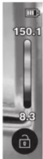
To determine the temperature of a specific field, move the measuring device so that the marker with the temperature display (m) is directed at the desired point or field. In the automatic setting, the color spectrum of the scale is continuously distributed over the entire measuring field within the maximum and minimum temperature (= uniform).
The measuring tool displays all measured temperatures in the measuring field in relation to each other. If, for example, a field is shown in color, with blue representing heat on the color palette, this means that the blue areas belong to the cooler measured values of the current measuring field. However, these areas may be within a temperature range that could lead to injuries under certain circumstances. Therefore, always pay attention to the displayed temperatures on the scale or directly on the indicator.
Functions
Follow the information for navigating through the various menus (see "Navigating through the various menus", page 267)

Illuminating the measuring object
The measuring tool is equipped with a work light (4).
It is intended for illuminating the direct work area of the measuring tool for capturing images and does not serve as a permanent work light.
To switch the work light on/off, go to the left sidebar. Scroll to the menu item / and confirm the source. When the work light is switched on, this is displayed in the status bar.
The light will automatically switch off after 2 minutes to avoid affecting the accuracy of the measurement.
You can set the time for automatic switch-off in the menu under <Tool settings>.
Overlaying thermal and real image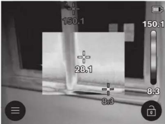
For better orientation (= spatial assignment of the displayed thermal image), the visual real image can also be switched on additionally when the temperature ranges are aligned.
Note: The overlay of the real and thermal image is exactly aligned at a distance of 1 m. If the distances to the measuring object differ, there will be a shift between the real and thermal image. This shift can be aligned with the appropriate Bosch apps. Information about the apps and their compatibility can be found on the measuring tool's page or at www.bosch-professional.com/thermal.
The measuring tool offers you the following options:
- 100% infrared image
Only the thermal image is displayed.

Transparency
The displayed thermal image is transparently
overlaid on the real image. This allows for better recognition of objects.
To activate/deactivate this setting, go to the left sidebar and scroll to the menu item <Vis. image on>/<Vis. image off>. Confirm the selection by pressing the multifunction button (17) in the center.
- Picture-in-picture
The displayed thermal image is cut out, and the remaining part is shown as the real image. This setting improves the local assignment of the measurement field.
To activate/deactivate this setting, go to the left sidebar and scroll to the menu item <Pic. in pic. on>/<Pic. in pic. off>. Confirm the selection by pressing the multifunction button (17) in the center.
Adjusting the color display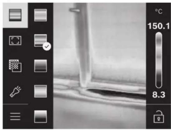
Depending on the measurement situation, different color palettes can facilitate the analysis of the thermal image and display objects and situations more clearly on the screen. This does not affect the measured temperatures. Only the display of temperature values changes.
To change the color palette, go to the sidebar and scroll to the menu item "Color palette". Confirm the selection by pressing the multifunction button (17) in the center.
Fixing the scale
The adjustment of the color distribution of the thermal image is done automatically, but it can be fixed by pressing the multifunction button (17) to the right, then in the center. This allows for comparing thermal images taken under different temperature conditions (e.g., when checking thermal bridges in multiple rooms) or fading out an extremely cold or hot object in the thermal image that would otherwise disturb it (e.g., a heating element as a hot object when searching for thermal bridges).
To return the scale to automatic, go to the right sidebar and press the multifunction button (17) in the center. The temperatures are now dynamic again and adjust to the measured minimum and maximum values.
Main menu
Access the left sidebar (see "Navigating through different menus", Page 267). To go to the main menu, press the multifunction button (17) in the center.
- <Gallery> Under this menu item you can delete saved images individually or all at once.
- <Measurement parameters>
- <Emission level> (a)
For some of the most common materials, saved emission levels are available. For easier searching, the values are grouped in the emission catalog. In the <Material catalog> menu item, first select the appropriate category and then the appropriate material. If you know the exact emission level of your measuring object, you can set it as a numerical value in the <User-defined> menu item.
• <Reflected temperature> (b)
Setting these parameters can improve the measurement result, especially for materials with a low emission level (= high reflection). In some situations (especially indoors), the reflected temperature corresponds to the ambient temperature. If objects with strongly deviating temperatures near highly reflective objects can influence the measurement, you should adjust this value. To do this, press the multifunction button (17) left or right.
- <Temperature range>
To ensure a high level of accuracy over the entire measurement range, measurement is performed in 2 temperature ranges. In the <Automatic> measurement function, the measuring tool automatically selects the appropriate temperature range based on the temperature distribution of the thermal image. This evaluates how many measured values are above a certain temperature threshold. If very small but hot objects need to be measured, the low temperature range can be selected, which is unsuitable for high temperatures. This can be recognized by the preceding \~ symbol on the temperature display. In this case, switch to the <100 °C ... 450 °C> or <-20 °C ... 100 °C> measurement function, in which the color distribution corresponds to the set temperature range. The setting is indicated on the scale with an up or down arrow.
- <Display settings>
- <Center point> (m): <ON>/<OFF>
The point is displayed centrally on the thermal image and shows you the measured temperature value at this location.
- <Hot spot> (n): <ON>/<OFF>
The hottest point (= measuring pixel) is marked with a red marker on the thermal image. This makes it easier to search for critical locations (e.g., loose contact terminals in a distribution box).
• <Cold spot> (I): <ON>/<OFF>
The coldest point (= measuring pixel) is marked with a blue marker on the thermal image. This makes it easier to search for critical locations (e.g., window locations that do not seal properly).
- <Temperature scale> (i): <ON>/<OFF>
- <Average temperature> (s): <ON>/<OFF> The average temperature (s) is displayed at the top left of the thermal image (average temperature of all measured values on the thermal image). This can help you determine the reflected temperature.
- <Tool settings>
- <Screen brightness>
Under this menu item, you can adjust the brightness of the screen.
-
Under this menu item, you can select the time interval for automatically turning off the work light if no button is pressed.
- <Tool turns off after...>
In this menu item, you can select a time interval after which the measuring device will automatically turn off if no button is pressed. You can also deactivate the automatic shutdown by selecting the <Never> setting.
- <Date and time>
In this submenu, in addition to the time and date setting, you can also change their respective formats.
In this menu item, you can select the language to be used on the display.
- <Factory settings>
In this menu item, you can reset the measuring device to factory settings and permanently delete all data. This may take a few minutes. Press the multifunction button (17) on the right to delete all files, or the multifunction button (17) on the left to cancel the process.
- <Information>
In this menu item you can call up information about the measuring device. There you will find the serial number of the measuring device and the installed software version. You can also find additional information about the measuring device and software updates there.
To exit the menu and return to the standard display screen, you can also press the Measure button (6).
Software update for the measuring device
If necessary, you can update the software of the measuring device via the USB Type-C® interface. More information can be found at: www.bosch-professional.com/thermal-update.
Documenting measurement results
Saving measurement results
Immediately after switching on, the measuring device starts measuring and continues continuously until it is switched off.
To save an image, point the camera at the desired measuring object and press the Measure button (6).
The image is saved in the internal memory of the measuring device. The measurement freezes and is displayed on the screen. This allows you to carefully examine the image and make additional adjustments (e.g., color palette). If you do not want to save the frozen image, reset the measuring mode with the Measure button (6).
If you want to save the image in the internal memory of the measuring device, press the multifunction button (17) in the middle.
Calling up saved images
To call up saved thermal images, proceed as follows:
– Immediately after saving, press the multifunction button (17) in the middle again. The preview of the last saved photo now appears on the screen. – Alternatively, you can access the saved photos in the <Gallery> menu item. - To switch between saved thermal images, press the multifunction button (17) to the right or left.
Additionally, a visual image can be saved along with the thermal image. To access this, press the multifunction button (17) up or down.
After 5 seconds, the measuring device switches to full-screen display. In full-screen display, the title bar is hidden so you can see all details of the thermal image.
You can change the views by pressing the multifunction button (17) up or down.
Deleting saved images
To delete individual or all thermal images, press the multifunction button (17) in the middle. A submenu opens.
– Here you can choose whether you want to delete only this image or all images. Confirm your selection with the multifunction button (17) in the middle. If you select <Delete>, you can choose between <Delete all> and <Cancel>. Confirm your selection with the multifunction button (17) in the middle. - In this submenu you can also view the information about the emission level and the reflected temperature.
Fragments of image data remain in the memory and could be reconstructed. For final deletion, select <Tool settings> → <Factory settings> in the main menu.
Data transfer
Data transfer via USB interface
Open the cover (11) of the USB Type-C® connector. Connect the USB Type-C® port (12) of the measuring device to your computer using the USB Type-C® cable (16).
Now switch on the measuring device with the on/off button (18).
Open the file browser on your computer and select the drive GTC_450. The saved files can be copied from the internal memory of the measuring device, moved, or deleted on your computer.
Once you have completed the desired process, properly eject the drive from the computer and then switch off the measuring device again with the on/off button (18).
Caution: Always eject the drive from your operating system first (remove the drive), otherwise the internal memory of the measuring device may be damaged.
Remove the USB Type-C® cable and close the cover (11).
The cover of the USB interface should always be closed to prevent dust or water from entering the housing.
Note: Connect the measuring device via USB exclusively to a computer. The measuring device can be damaged if you connect it to other devices.
Note: The USB Type-C ® interface is used exclusively for data transfer. It should not be used to charge batteries or rechargeable batteries.
Additional processing of thermal images
You can subsequently process the saved thermal images with the appropriate Bosch applications. Information about the applications and their compatibility can be found on the measuring tool's page or at www.bosch-professional.com/thermal.
Malfunction – causes and assistance
In the event of a malfunction, the measuring device resets and can then be used again. Otherwise, the overview below will help you with persistent error messages.
Error Cause Assistance
| Мерниот уред не може да севклучи. | Акумулаторската батерија/Батеријата е празна | Наполнете ја акумулаторска батерија одн. заменете гибатериите. | |
 | Дефект во акумулаторскатабатерија/батериите | Заменете ја акумулаторската батерија одн. батериите. | |
 | Акумулаторската батерија/батеријата е премногу топлаодн. ладна | Оставете ја акумулаторската батерија да се излади илипроменете ја акумулаторската батерија одн. батериите. | |
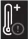 | Мерниот уред е премногутопол одн. ладен | Оставете го мерниот уред да се темперира. | |
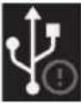 | USB-приключокот или USB-кабелот се дефектни | Проверете дали мерниот уред може да се поврзе со другкомпјутер. Доколку не може, однесете го мерниот уред воовластенаBosch-сервисна служба. | |
| Мерниот уред не може да сеповрзе со компјутер. | Напомена:секогаш користете го USB-кабелот включен воиспораката. | ||
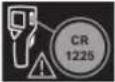 | Копчестата батерија епразна | Заменете ја копчестата батерија (види „Замена накопчестата батерија (види слика C )“, Страница 273).Потврдете ја промената со „Во ред“ намултифункционалното копче(17)во средина. | |
Explanation of terms
You can find more information at www.bosch-professional.com/thermal.
Infrared thermal radiation
Infrared thermal radiation is electromagnetic radiation emitted by every body above 0 kelvin (-273 °C). The amount of radiation depends on the temperature and the emissivity of the body.
Emissivity
The emissivity of an object depends on the material and structure of its surface. It indicates how much infrared thermal radiation the object emits compared to an ideal thermal emitter (black body, emissivity є = 1) and has a value between 0 and 1.
Thermal bridges
A thermal bridge is defined as a location on the exterior of a building where, due to the construction, there is a locally increased heat loss.
Thermal bridges can lead to an increased risk of mold.
Reflected temperature/object reflection
Reflected temperature is thermal radiation that does not come from the object itself. Depending on the structure and material, surrounding radiation is reflected into the object to be measured, thereby distorting the actual temperature result.
Distance to the object
The distance between the measuring object and the measuring device affects the size of the surface area captured per pixel. With increased distance to the object, larger objects can be registered.
| Оддалечување (m) | Големи инфрацрвени пиксели (mm) | Ширина × висина на инфрацрвено поле (m) |
| 0,30 1,14 ~ 0,29 × 0,22 | ||
| 0,55 2,08 ~ 0,53 × 0,40 | ||
| 1,00 3,79 ~ 0,97 × 0,73 | ||
| 2,00 7,58 ~ 1,94 × 1,46 | ||
| 5,00 18,95 ~ 4,85 × 3,64 | ||
Maintenance and service
Maintenance and cleaning
Store and transport the measuring device only in a suitable container or in the original packaging.
Keep the measuring device clean at all times. A dirty infrared sensor (5) can affect measurement accuracy.
Liquid must not enter the measuring tool during cleaning.
Do not attempt to remove dirt from the infrared sensor (5), camera (3), work light (4), or laser outlet opening (2) with sharp objects.
Do not wipe the infrared sensor and camera (risk of scratches).
Regularly clean the surfaces around the laser outlet opening, paying attention to lint.
If you wish to recalibrate your measuring device, contact an authorized Bosch service center.
If repair is required, send the measuring tool in its original packaging.
There are no user-serviceable parts on the measuring device. Opening the housing cover can damage the measuring device.
Replacing the button battery (see figure C)
Open the cap (11).
Unscrew the screw (10) from the button battery holder. Pull the button battery holder (9) out of the measuring device. Replace the button battery. Retighten the screw (10) after inserting it into the button battery holder.
Service department and usage advice
The service department will answer your questions regarding the repair and maintenance of your product as well as spare parts. Exploded drawings and information on spare parts can also be found at:
www.bosch-pt.com
The Bosch usage advice team will help you if you have questions about our products and accessories.
For all questions and spare parts orders, please quote the 10-digit number from the product nameplate.
North Macedonia
D.D. Electris
Sava Kovačević 47N, no. 3
1000 Skopje
E-mail: dimce.dimcev@servis-bosch.mk
Internet: www.servis-bosch.mk
Tel./fax: 02/ 246 76 10
Mob.: 070 595 888
D.P.T.U. "ROZHKA"
Jani Lukrovski 66; T.C. Avtokomanda lok. 69
1000 Skopje
E-mail: servisrojka@yahoo.com
Tel: +389 2 3174-303
Mob.: +389 70 388-520, -530
Additional service addresses can be found at:
www.bosch-pt.com/serviceaddresses
Transport
The recommended Lithium-ion batteries are subject to the requirements of the Dangerous Goods Act. Batteries can be transported by the user without the need for additional qualifications.
When shipping via third parties (e.g., air transport or freight forwarding), special attention must be paid to the packaging and labeling instructions. In such a case, an expert for hazardous substances must be consulted when preparing the shipment.
Transport the batteries only if the housing is undamaged. Tape off open contacts and pack the battery in such a way that it cannot move around in the packaging. Please observe any additional national regulations.
Disposal

Measuring tools, rechargeable batteries/batteries, accessories, and packaging should be disposed of in an environmentally friendly manner.
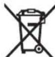
Do not throw measuring tools and batteries into household waste!
For EU countries only:
Measuring tools that are no longer usable and are defective, or used rechargeable batteries/batteries, must be disposed of separately. Use the designated collection systems.
If disposed of improperly, waste electrical and electronic equipment can have harmful effects on the environment and human health due to the possible presence of hazardous substances.
Rechargeable batteries/batteries:
Lithium-ion:
Please note the instructions in the Transport section (see "Transport", page 273).
Serbian
Safety Notes

You must read and follow all instructions to work with the measuring tool safely and without danger. If the measuring tool is not used in accordance with the
instructions provided, the protective systems integrated in the measuring tool may be compromised. Do not allow the warning labels on the measuring tool to become illegible. KEEP THESE INSTRUCTIONS IN A SAFE PLACE AND PASS THEM ON WITH THE TOOL IF YOU GIVE IT TO SOMEONE ELSE.
Caution – If you use other devices for operation or adjustment than those specified here, or if you carry out other procedures, this may lead to dangerous exposure to radiation.
274 | Serbian
▶ The measuring tool is supplied with a laser warning label (marked in the illustration of the measuring tool on the graphics page). If the text on the laser warning label is not in your language, cover it with the supplied label in your language before first use.
Do not direct the laser beam at people or animals and do not look into the direct or reflected laser beam. This can blind people, cause accidents, or damage eyes.
If laser radiation enters the eye, you must consciously close your eyes and immediately turn your head away from the beam.
▶ Do not make any modifications to the laser equipment.
▶ Do not use laser glasses (accessory) as protective goggles. Laser glasses are used to better recognize the laser beam. However, they do not protect against laser radiation.
▶ Do not use laser glasses (accessory) as sunglasses or in traffic. Laser glasses do not provide complete UV protection and reduce color perception.
▶ The measuring tool may only be repaired by qualified personnel and only with original spare parts. This ensures that the safety of the measuring tool is maintained.
▶ Do not allow children to use the laser measuring tool without supervision. They could unintentionally blind others or themselves.
▶ Do not work with the measuring tool in an explosive environment where flammable liquids, gases, or dusts are present. Sparks may be generated in the measuring tool, which could ignite dust or fumes.
▶ Do not modify or open the battery. There is a risk of short circuit.
In case of damage and improper use of the battery, vapors may be emitted. The battery can burn or explode. Get fresh air and seek medical attention if you experience discomfort. Vapors can irritate the respiratory tract.
In case of incorrect use or damage to the battery, flammable liquid may leak from the battery. Avoid contact with it. In case of accidental contact, rinse with water. If the liquid gets into the eyes, also seek medical help. Liquid leaking from the battery can cause skin irritation or burns.
The battery can be damaged by sharp objects, such as nails or screwdrivers, or by external force. An internal short circuit may occur, and the battery can burn, smoke, explode, or overheat.
Keep unused battery away from paper clips, coins, keys, nails, screws, or other small metal objects that can bridge the contacts. A short circuit between the battery contacts can result in burns or fire.
- Use the battery only with products from this manufacturer. Only then is the battery protected against dangerous overload.
▶ Charge batteries only with chargers recommended by the manufacturer. If a charger suitable for one type of battery is used with batteries of another type, there is a risk of fire.

Protect the battery from heat sources, e.g., also from prolonged direct sunlight, fire, dirt, water, and moisture. There is a risk of explosion and short circuit.

WARNING

Ensure that the button battery is kept out of the reach of children. Button batteries are dangerous.
Button batteries must never be swallowed or inserted into other body orifices. If there is any suspicion that a button battery has been swallowed or is located in other body orifices, seek medical attention immediately. Swallowing a button battery can lead to severe internal burns and death within 2 hours.
▶ When replacing the button battery, make sure you replace it correctly. There is a risk of explosion.
▶ Use only button batteries specified in these operating instructions. Do not use other button batteries or other power sources.
▶ Do not attempt to recharge the button battery and do not short-circuit it. The button battery may leak, explode, catch fire, and cause injury.
Dispose of exhausted button batteries according to regulations. Exhausted button batteries may leak and damage the product or cause injury.
Do not overheat the button battery or throw it into fire. The button battery may leak, explode, catch fire, and cause injury.
Do not damage or disassemble the button battery. The button battery may leak, explode, catch fire, and cause injury.
A damaged button battery must not come into contact with water. Leaked lithium can form hydrogen with water, which can cause fire, explosion, or injury.
If the button battery compartment can no longer be closed properly and completely, do not use the measuring tool anymore, remove the button battery, and send the measuring tool for repair.
Large temperature differences in the thermal image can cause even high temperatures to be displayed in a color associated with low temperatures. Contact with such a surface can lead to burns.
Correct temperature measurements are only possible if the set emissivity and the emissivity of the object match. Objects may be displayed at higher or lower temperatures, which can lead to potential hazards upon contact. ▶ Do not point the measuring tool directly at the sun or strong CO₂ lasers. This can damage the detector. ▶ Protect the measuring tool, especially the camera area and the infrared lens, from moisture, snow, dust, and dirt. The receiving lens can become fogged or dirty and lead to incorrect measurement results.
Incorrect device settings as well as other atmospheric influences can lead to incorrect measurement results.
Objects may be displayed at higher or lower temperatures, which can lead to danger upon contact.
Product description and applications
Please refer to the images on the front of the instruction manual.
Intended use
This thermal imaging camera is intended for non-contact measurement of surface temperatures.
The displayed thermal image shows the temperature distribution of the camera's field of view, thus enabling a differentiated color display of temperature deviations.
If you use the device correctly, you can non-contact inspect surfaces and objects for temperature differences and irregularities, to display components and/or weak points, among others:
- thermal insulation and insulation (e.g., detection of thermal bridges),
- active heating and hot water lines (e.g., underfloor heating) in floors and walls,
- overheated electrical components (e.g., fuses or terminals),
- defective or damaged machine parts (e.g., overheating due to a faulty ball joint).
The measuring tool is not suitable for measuring the temperature of gases.
The measuring tool must not be used for medical purposes.
For applications in the field of veterinary medicine, please inform yourself online at www.bosch-professional.com/thermal.
The measuring tool is suitable for use in outdoor and indoor areas.
This product is a consumer laser product in accordance with standard EN 50689.
The light of this measuring tool is intended to illuminate the direct working area of the measuring tool to create images and is not intended for permanent work lighting.
The laser point must not be used as a laser pointer.
It serves exclusively to mark the surface for measurement.
Displayed components
The numbering of components in the figure refers to the representation of the measuring tool on the graphic page.
(1) Protective cap (2) Laser beam outlet
(3) Visual camera
(4) Work light
(5) Infrared sensor
(6) Pause/start measurement button
(7) Battery compartment
(8) Laser warning label
(9) Button battery holder
(10) Button battery holder screw
(11) Cover for USB socket and coin battery holder
(12) USB Type-C® socket a)
(13) Laser button
(14) Unlocking button for battery adapter
(15) Rechargeable battery b)
(16) USB Type-C® cable b)
(17) Multifunction button
(18) On/off button / Back button
(19) Display
(20) Serial number
(21) Case for battery adapter
(22) Batteries b)
(23) Cap for closing the battery adapter
a) USB Type-C® and USB-C® are trademarks of USB Implementers Forum.
b) Shown or described accessories are not included in the standard delivery scope.
Display elements
(a) Emission level display (b) Reflected temperature display (c) Average temperature display (d) Full memory symbol (e) Work light symbol (f) Laser symbol (g) Charge status display (h) Maximum surface temperature display in the measuring area
(i) Scale
(j) Minimum surface temperature display in the measuring area
(k) Temperature scale locking symbol
(l) Cold spot display (example)
(m) Crosshair with temperature display
(n) Hot spot display (example)
(o) Menu symbol
Technical data
| Termovizijska kamera GTC 12V-450-13 | |
| Broj artikla | 3 601 K83 900 |
| Rezolucija infracrvenog senzora 256 × 192 px | |
| Termička osetljivostA) | ≤ 50 mK |
| Spektralni opseg 8–14 μm | |
| Vidno polje (FOV)A) | 55,6° × 42° |
| Prostorna rezolucija (IFOV) 3,79 mrad | |
| Udaljenost fokusaA) | ≥ 0,5 m |
| Fokus fiksno | |
| Brzina osvežavanja termovizijske slike ≤ 9 Hz | |
| Merni opseg površinske temperatureA) | -20 ... +450 °C |
| Preciznost merenja temperature površineA)(B)(C) | |
| >0 °C ... ≤ +100 °CD) | ±2 °C |
| >+100 °CE) | ±2% |
| Rezolucija pri merenju temperature 0,1 °C | |
| Tip displeja TFT | |
| Veličina displeja 2,8" | |
| Rezolucija displeja 480 × 360 px | |
| Rezolucija integrisane vizuelne kamere 2 MP (640 × 480 px) | |
| Format slike .jpg | |
| Memorisani elementi po postupku memorisanja 1 × termovizijska slika (snimak ekrana),1 × vizuelna realna slika uklj. vrednosti temperature (meta podaci) | |
| Maks. broj slika u internoj memoriji slika 500 | |
| Maks. radna visina iznad referentne visine 2000 m | |
| Stepen zaprljanosti prema standardu IEC 61010-1 2 | F) |
| Maks. relativna vlažnost vazduhaA) | 90% |
| Klasa lasera | 2 |
| Tip lasera | < 1 mW, 645–660 nm |
| Divergencija laserskog zraka | 1,5 mrad (pun ugao) |
| Snabdevanje energijom | |
| - Akumulator (litijum-jonski) | 12 V |
| - Baterije (alkalno-magnanske sa adapterom za baterije) | 4 × 1,5 V LR6 (AA) |
| - Akumulatori (NiMH sa adapterom za baterije) | 4 × 1,2 V HR6 (AA) |
| Trajanje radaC) | |
| - Akumulator (litijum-jonski)H) | 8 h |
| - Baterije (alkalno-magnanske) | 4 h |
| Snabdevanje energijom za sistemsko vreme | CR1225 (litijumska baterija od 3 V) |
| USB standard | 2.0 |
| USB interfejs | USB Type-C® |
| TežinaJ) | 0,354 kg |
| Dimenzije (dužina × širina × visina)K) | 89 × 79 × 209 mm |
Thermal imaging camera GTC 12V-450-13
| Vrsta zaštite (osim akumulatora/baterija, u uspravnom položaju) | IP54 |
| Preporučena temperatura okruženja prilikom punjenja 0 °C ... +35 °C | |
| Dozvoljene temperature okruženja | |
| - Prilikom rada -10 °C ... +50 °C | |
| - Prilikom skladištenja sa akumulatorom -20 °C ... +50 °C | |
| - Prilikom skladištenja bez akumulatora -20 °C ... +70 °C | |
| Preporučeni akumulatori GBA 12V... | |
| Preporučeni punjači GAL 12... | GAX 18... |
A) According to VDI 5585 standard (average value) B) At ambient temperature 20–23 °C and emission level > 0.95, measuring distance: 1 m, operating time: > 5 min, aperture 150 mm, with work light and laser off C) With application-dependent deviations (e.g., reflection, distance, ambient temperature) D) Applies to the center point, for all other pixels additional ±1 °C E) Applies to the center point, for all other pixels additional ±1% F) Non-conductive contamination occurs, with temporary conductivity expected due to condensation. G) With work light off and medium display brightness H) Depending on the battery used I) At ambient temperature 20-30°C J) Weight without battery/battery adapter/batteries K) With GBA 12V 2.0Ah or battery adapter The serial number (20) on the type plate serves for unambiguous identification of the measuring tool.
Power supply for the measuring tool
The measuring tool can operate either with a Bosch lithium-ion battery, with conventional batteries, or with NiMH rechargeable batteries.
Working with the rechargeable battery (see figure A)
Only use the chargers listed in the technical data. Only these chargers are compatible with the lithium-ion battery used in your measuring tool.
Note: Lithium-ion batteries are delivered partially charged due to international transport regulations. To ensure full battery power, fully charge the battery before first use.
To insert the charged battery (15), push it into the battery compartment (7) until it audibly clicks into place.
To remove the battery (15), press the release buttons (14) and pull the battery out of the battery compartment (7). Do not use force.
Working with batteries (see figure B)
For operating the measuring tool, the use of alkaline manganese batteries or NiMH rechargeable batteries is recommended.
The batteries are placed in the battery adapter.
The battery adapter is intended exclusively for use in designated Bosch measuring tools and must not be used with power tools.
To insert the batteries, push the sleeve (21) of the battery adapter into the battery compartment (7). Insert the batteries according to the illustration on the closing cap (23) into the sleeve. Push the closing cap over the sleeve until it audibly clicks into place.
To remove the batteries (22), press the release buttons (14) of the closing cap (23) and remove the closing cap. Take out the batteries. To remove the sleeve (21) from the battery compartment, grasp the sleeve and pull it out of the measuring tool with light pressure on the side wall.
Always replace all batteries or rechargeable batteries at the same time. Only use batteries or rechargeable batteries from one manufacturer and with the same capacity.
Remove the batteries or rechargeable batteries from the measuring tool if you will not be using it for an extended period. In case of longer storage, the batteries and rechargeable batteries in the measuring tool could corrode.
Instructions for optimal handling of the rechargeable battery
Protect the rechargeable battery from moisture and water.
Store the battery only in a temperature range of -20 °C to 50 °C. Do not leave the battery in the car in summer, e.g.
Significantly shortened operating time after charging indicates that the battery is worn out and must be replaced.
Pay attention to the disposal instructions.
Operation
▶ Protect the measuring tool from moisture and direct sunlight. ▶ Do not expose the measuring tool to extreme temperatures or temperature fluctuations. For example, do not leave it in a car for an extended period. In case of large temperature fluctuations, allow the measuring tool to acclimatize before putting it into operation. Extreme temperatures or temperature fluctuations can affect the accuracy of the measuring tool. Ensure that the measuring tool acclimatizes properly. In case of large temperature fluctuations, the acclimatization time can be up to 60 minutes. This can happen, for example, if you store the measuring tool in a car and then take measurements in a warm building. Avoid strong impacts or drops of the measuring tool. After strong external influences and in case of noticeable changes in function, the measuring tool should be checked by an authorized Bosch service center.
Start-up
On first switching on
When switching on the measuring tool for the first time or after resetting to factory settings, some basic settings must be performed. Press the multifunction button (17) down, up, left, or right to select the desired value. Press the multifunction button (17) in the middle to confirm the selection. After confirming the selection, the next setting is displayed on the screen. The total number and the number of remaining settings are shown in the status bar at the top.
The following basic settings are available:
Switching on/off
For measuring, fold open the protective cap (1). During operation, ensure that the infrared sensor is not closed or covered.
To switch on the measuring tool, press the on/off button (18). The start sequence is shown on the display (19). After the start sequence, the measuring tool immediately begins measuring and continues to do so until it is switched off.
Note: In the first few minutes, the measuring tool may level itself more frequently on its own, because the sensor temperature and the ambient temperature have not yet adjusted. Re-adjustment of the sensor enables precise measurement. During this time, the temperature display may be marked with \~. If there are large fluctuations in ambient temperature, this effect is intensified. Therefore, switch on the measuring tool a few minutes before starting measurement so that it can thermally stabilize.
To switch off the measuring tool, press the on/off button (18) for > 1 s. The measuring tool saves all settings and then switches off. For safe transport of the measuring tool, close the protective cap (1).
In the main menu, you can choose whether and after how long the measuring tool will automatically switch off (see "Main menu", page 280).
If the battery or the measuring tool has an operating temperature outside the range specified in the technical data, the measuring tool will automatically switch off after a brief warning (see "Error – causes and remedies", page 282). Allow the measuring tool to acclimate to the ambient temperature and then switch it on again.
Navigating through the various menus
Navigating through the various menus of the measuring tool:
- Calling up the menu bars: Press the multifunction button (17) in the middle or on the left. The menu bars on the right and left are displayed on the screen, with the main menu highlighted.
- Scrolling in the left menu bar/navigating through the main menu: press the multifunction button (17) up, down, left, or right.
- Switching to the left or right menu bar: press the multifunction button (17) left or right.
- Confirming a selection/entering a submenu: press the multifunction button (17) in the middle. – Returning from a submenu to the parent menu: press the Back button (18).
Preparing for measurement
Setting the emission level for surface temperature measurement
The emission level of an object depends on the material and the structure of its surface. It indicates how much infrared heat radiation the object emits compared to an ideal heat source (black body, emission level ε = 1) and is a value between 0 and 1.
To determine the surface temperature, the natural infrared heat radiation emitted by the target object is measured without contact. For correct measurement, the emission level must be checked on the measuring tool before each measurement and, if necessary, adjusted to the measurement object.
The emission levels programmed in the measuring tool are reference values.
You can select one of the programmed emission levels or enter an exact numerical value. Set the desired emission level in the menu → (see "Main menu", page 280).
▶ Correct temperature measurements are only possible if the set emission level and the emission level of the object match.
The lower the emissivity, the greater the influence of reflected temperature on the measurement result. Therefore, always adjust the reflected temperature when changing the emissivity. Set the reflected temperature in the menu → (see "Main menu", page 280).
Temperature differences displayed by the measuring tool may be due to different temperatures and/or different emissivities. With greatly differing emissivities, the displayed temperature differences may deviate significantly from the actual ones.
If there are several measurement objects made of different materials or with different surface structures within the measuring range, the displayed temperature values are only accurate for objects that match the set emissivity. For all other objects (with different emissivity), the displayed color differences can be used as an indication of temperature relationships.
Instructions for starting measurement
Surfaces with strong reflection or shiny surfaces (e.g., glossy tiles or bare metal) can distort or adversely affect the displayed results. If necessary, cover the measuring surface with a dark, matte adhesive tape that conducts heat well. Wait briefly for the tape to acclimate to the surface temperature. For reflective surfaces, pay attention to a favorable measuring angle so that thermal radiation reflected from other objects does not lead to incorrect measurement results. For example, when measuring vertically from the front, reflection of your body heat can adversely affect the measurement. On a flat surface, this can display the silhouette and temperature of your body (reflected value), which does not correspond to the actual temperature of the measured surface (actual value or true surface value).
Measurement through transparent materials (e.g., glass or transparent plastic) is generally not possible.
Measurement results are more accurate and reliable when the measurement conditions are better and more stable. Not only strong fluctuations in ambient temperature are relevant; strong fluctuations in the temperature of the measured object can also negatively affect accuracy.
Infrared temperature measurement is degraded by smoke, steam/high humidity, or dust in the air.
Notes for better measurement accuracy:
- To reduce interfering factors between you and the measuring surface, get as close as possible to the measurement object.
- Therefore, ventilate the room before measuring, especially if the air is polluted or has steam. Wait for the room to acclimate after ventilation until it reaches its usual temperature again.
Marking the measurement spot
▶ Do not point the laser beam at people or animals and do not look into the laser beam, even from a distance.
The measuring tool has a laser for marking the measurement spot.
Press the laser button (13) and hold it down. The laser symbol (f) appears in the status bar and a red circle is displayed around the crosshair (m). The laser and crosshair overlap precisely at a distance of 1 m. When you release the laser button (13), the laser switches off.
Determining temperatures based on the scale
On the right side of the display, a scale (i) is shown. The values at the top and bottom are oriented to the maximum (h) and minimum temperature (j) respectively, which are displayed on the thermal image. The scale uses 99.99% of the total pixels. The assignment of colors to temperature values in the image is done uniformly (linearly).
In this way, temperatures can be assigned to these limit values using different color shades. For example, the temperature exactly between the maximum and minimum values is assigned to the middle color range on the scale.
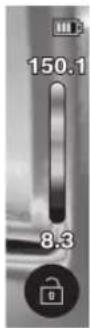
To determine the temperature of a specific area, move the measuring tool so that the crosshair with the temperature display (m) is aimed at the desired point or area. In automatic adjustment, the color spectrum on the scale is always distributed linearly (= uniformly) over the entire measuring range within the maximum and minimum temperature.
The measuring tool shows all measured temperatures in the measuring range in relation to each other. If, for example, in one area, heat is displayed in blue on the color scale, this means that blue areas represent colder measured values in the current measuring range. These areas can be in a temperature range that could potentially lead to injuries. Therefore, always pay attention to the displayed temperatures on the scale or directly on the crosshair.
Functions
See the information on navigation in the various menus (see "Navigating through the various menus", page 278)

Illuminating the measurement object
The measuring tool has a work light (4). It is intended for illuminating the direct working area of the measuring tool for taking pictures and is not intended for permanent work lighting.
To switch the work light on/off, call up the left side bar. Scroll to the menu item <LED lamp
on>/ and confirm the selection. When the work light is switched on, the status bar is displayed.
The light automatically switches off after 2 minutes so that it does not affect the measurement accuracy.
You can set the automatic switch-off time in the menu under .
Overlaying the thermal image and the real image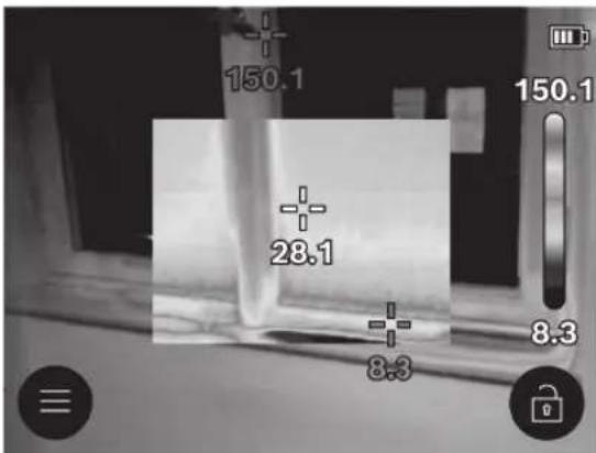
For better orientation (= spatial assignment of the displayed thermal image), you can additionally switch on the visual real image for uniform temperature ranges.
Note: The overlay of the real and thermal image is precise at a distance of 1 m. At other distances to the measuring object, a deviation between the real and thermal image generally occurs. This deviation can be compensated using special Bosch applications. Information about applications and compatibility can be found on the product page for measuring tools or at www.bosch-professional.com/thermal.
The measuring tool offers the following options:
- 100% infrared image
Only the thermal image is displayed.

- Transparency
The displayed thermal image is placed transparently over the real image. This makes it easier to recognize the object.
To activate/deactivate the setting, call up the left side bar and scroll to the menu item / . Confirm the selection by pressing the multifunction button (17) in the center.
- Picture-in-picture
The displayed thermal image is cropped and the surrounding area is shown as a real image. This setting improves spatial orientation of the measuring area.
To activate/deactivate the setting, call up the left side bar and scroll to the menu item / . Confirm the selection by pressing the multifunction button (17) in the center.
Adjusting the color display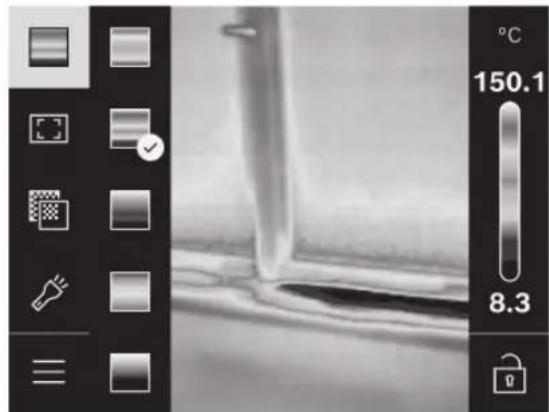
Depending on the measuring situation, different color palettes can facilitate the analysis of the thermal image and display objects or factual conditions more clearly on the screen. This does not affect the measured temperatures. Only the display of temperature values changes.
To change the color palette, call up the side bar and scroll to the menu item "Color palette". Confirm the selection by pressing the multifunction button (17) in the center.
Fixing the scale
The adjustment of the color distribution on the thermal image is done automatically, but can also be fixed by pressing the multifunction button (17) to the right and then in the center. This enables comparison of thermal images taken under different temperature conditions (e.g., when checking thermal bridges in multiple rooms) or excluding extremely cold or hot objects from the thermal image that would otherwise distort the image (e.g., a heating element as a hot object when searching for thermal bridges).
To switch the scale back to automatic, call up the right side bar and press the multifunction button (17) in the center. The temperatures will then behave dynamically again and adapt to the minimum and maximum values.
Main menu
Call up the left side bar (see "Navigating through the different menus", Page 278). To access the main menu, press the multifunction button (17) in the center.
- In this menu item, you can delete stored images individually or all at once.
-
- (a)
For some of the most common materials, stored emissivity levels are available. For easier searching, the values are divided into groups in the emissivity catalog. In the <Material catalog> menu item, first select the appropriate category, then the appropriate material. If you know the exact emissivity of the object being measured, you can
set it as a numerical value in the menu item .
set it as a numerical value in the menu item .
• (b)
Adjusting this parameter can improve the measurement result, especially for materials with low emissivity (= high reflectivity). In some situations (especially indoors), the reflected temperature corresponds to the ambient temperature. If objects with temperatures that deviate greatly from the object with strong reflection can influence the measurement, adjust this value. To do this, press the multifunction button (17) left or right.
-
For greater accuracy over the entire measuring range, measurement is carried out in 2 temperature ranges. In the measuring function, the measuring tool automatically selects the appropriate temperature range based on the temperature distribution in the thermal image. It assesses how many measured values are above a certain temperature threshold. If you want to measure very small but hot objects, it may happen that a lower temperature range is selected that is not suitable for high temperatures. You can recognize this by the \~ symbol on the temperature display. In that case, switch to the measuring function <100 °C ... 450 °C> or <-20 °C ... 100 °C>, in which the color distribution corresponds to the set temperature range. The setting is marked on the scale with an up or down arrow.
-
- (m): / The point is displayed in the center of the thermal image and shows the measured temperature value at that location.
- (n): / The hottest point (= measuring pixels) is marked with a red cross on the thermal image. This makes it easier to find critical spots (e.g., loose contact clamps in a distribution cabinet).
- (I): / The coldest point (= measuring pixels) is marked with a blue cross on the thermal image. This makes it easier to find critical spots (e.g., unsealed spots on a window). • (i): /
- (c): / The average temperature (c) is displayed at the top left of the thermal image (average temperature of all measured values on the thermal image). This can make it easier to determine the reflected temperature.
-
- In this menu item, you can adjust the brightness of the display lighting. • In this menu item, you can select the time interval for automatic shutdown of the work light when you do not press a button.
-
In this menu item, you can select the time interval after which the measuring tool will automatically shut down if no button is pressed. You can also deactivate the automatic shutdown by selecting the setting .
-
In this submenu, in addition to setting the time and date, you can also change the corresponding formats.
•
In this menu item, you can select the language used for display.
-
In this menu item, you can reset the measuring tool to factory settings and permanently delete all data. This may take a few minutes. Press the multifunction button (17) on the right to delete all files, or the multifunction button (17) on the left to cancel the process.
-
In this menu item, you can call up information about the measuring tool. There you will find the serial number of the measuring tool and the installed software version. There you can also view additional information about the measuring tool and software updates.
To exit a menu and return to the standard display screen, you can also press the measurement button (6).
Updating the measuring tool software
If necessary, you can update the measuring tool software via the USB Type-C® interface. For more information, visit: www.bosch-professional.com/thermal-update.
Documenting measurement results
Storing measurement results
The measuring tool starts measuring immediately after being switched on and continues to do so until it is switched off.
To store an image, point the camera at the desired measurement object and press the measurement button (6). The image is saved in the internal memory of the measuring tool. The measurement is frozen and displayed on the screen. This allows you to examine the image thoroughly and make subsequent adjustments (e.g., color palette). If you do not want to save the frozen image, press the measurement button (6) again to restart the measurement mode. If you want to store the image in the internal memory of the measuring tool, press the multifunction button (17) in the middle.
Recalling stored images
To recall stored images, proceed as follows:
- Immediately after storing, press the multifunction button (17) in the middle again. The display shows the last stored image.
- Alternatively, you can recall stored images via the menu item .
- To navigate through the stored thermal images, press the multifunction button (17) to the right or left.
In addition to the thermal image, a visual image was also stored. To open it, press the multifunction button (17) up or down.
After 5 seconds, the measuring tool switches to full-screen display. In full-screen display, the title bar is hidden so that all details of the thermal image are visible. By pressing the multifunction button (17) up and down, you can change the display.
Deleting saved images
To delete individual or all thermal images, press the multifunction button (17) in the middle. A submenu opens.
- Here you can choose whether you want to delete only that image or all images. Confirm the selection with the multifunction button (17) in the middle.
In the selection, you can also choose . Confirm the selection with the multifunction button (17) in the middle.
- In this submenu, you can also view information about the emission level and the reflected temperature.
Fragments of image data remain in memory and could be reconstructed. For definitive deletion, in the main menu select → .
Data transfer
Data transfer via USB port
Open the cover (11) of the USB Type-C® socket. Connect the USB Type-C® socket (12) of the measuring tool to the computer using the supplied USB Type-C® cable (16).
Then switch on the measuring tool using the on/off button (18).
On the computer, open the file explorer and select the drive GTC_450. The stored files can be copied from the internal memory of the measuring tool, transferred to the computer, or deleted. When you have finished the desired procedure, disconnect the drive from the computer in the usual way and switch off the measuring tool again using the on/off button (18).
Caution: Always eject the drive from the operating system first (eject the drive), otherwise the memory of the measuring tool could be damaged.
Remove the USB Type-C® cable and close the cover (11). The USB port cover should always be closed to prevent dust or splashing water from entering the housing.
Note: Connect the measuring tool to the computer only via the USB system. When connecting to other devices, the measuring tool may be damaged.
Note: The USB Type-C® interface is intended solely for data transfer. Batteries and rechargeable batteries cannot be charged via it.
Post-processing of thermal images
You can subsequently process saved thermal images using special Bosch applications. Information about the applications and compatibility can be found on the product page for measuring tools or at www.bosch-professional.com/thermal.
Error – causes and remedy
In the event of a malfunction, the measuring tool restarts and can then be used again. If this is not the case, the following overview provides assistance with persistent error messages.
Error Cause Remedy
| Merni alat ne može da se uključi. | Akumulator/baterije prazan/ prazne | Napunite akumulator odn. zamenite baterije. | |
 | Greška akumulatora/baterija Zamenite akumulator odn. baterije. | ||
 | Akumulator/baterije previše zagrejan/zagrejane odn. previše hladan/hladne | Sačekajte da se akumulator temperira ili zamenite akumulator odn. baterije. | |
 | Merni alat previše zagrejan odn. previše hladan | Sačekajte da se merni alat temperira. | |
 | USB priključak ili USB kabl neispravan | Proverite da li se merni alat može povezati sa drugim računarom. Ukoliko to nije slučaj, pošaljite merni alat ovlašćenomBoschkorisničkom servisu.Napomena:Uvek koristite USB kabl iz sadržaja isporuke. | |
| Merni alat se ne može povezati sa računarom. | |||
Error Cause Remedy
Button battery empty Replace the button battery (see "Replacing the button
battery (see figure C)", page 283). Confirm the replacement with
"OK" by pressing the multifunction button (17) in the middle.
Explanation of terms
Additional information can be found at www.bosch-professional.com/thermal.
Infrared heat emission
Infrared heat emission is electromagnetic radiation emitted by every body above 0 kelvin (-273 °C). The amount of radiation depends on the temperature and the degree of emission of the body.
Degree of emission
The degree of emission of an object depends on the material and the structure of its surface. It indicates how much infrared heat emission the object emits relative to an ideal heat source (black body, degree of emission ε = 1) and represents a value between 0 and 1.
Thermal bridge
A thermal bridge is a location on the exterior wall of a building where, due to the construction, there is a localized increased heat loss.
Thermal bridges can pose an increased risk of mold.
Reflected temperature/object reflection
Reflected temperature is heat emission that does not originate from the object itself. Depending on the structure and material, the object you are measuring reflects emissions from the surroundings, which corrupts the temperature result.
Distance from the object
The distance between the measurement object and the measuring tool affects the size of the area covered per pixel. As the distance from the object increases, you can capture larger objects.
| Rastojanje (m) Veličina infracrvenih piksela (mm) | Širina x visina infracrvenog područja (m) |
| 0,30 1,14 ~ 0,29 × 0,22 | |
| 0,55 2,08 ~ 0,53 × 0,40 | |
| 1,00 3,79 ~ 0,97 × 0,73 | |
| 2,00 7,58 ~ 1,94 × 1,46 | |
| 5,00 18,95 ~ 4,85 × 3,64 |
Maintenance and service
Maintenance and cleaning
Store and transport the measuring tool only in suitable packaging, such as the original packaging.
Always keep the measuring tool clean. A dirty infrared sensor (5) can negatively affect measurement accuracy.
During cleaning, no liquid must enter the measuring tool.
Do not use sharp objects to clean dirt from the infrared sensor (5), camera (3), work light (4), or the laser output opening
(2). Do not wipe a cloth over the infrared sensor and camera (risk of scratches).
Regularly clean especially the surfaces at the laser output opening and be careful of lint.
If you want to recalibrate the measuring tool, contact the authorized Bosch customer service.
When sending the measuring tool for repair, always send it in its original packaging.
There are no user-serviceable parts inside the measuring tool. Opening the housing may damage the measuring tool.
Replacing the button battery (see figure C)
Open the cover (11).
Unscrew the screw (10) of the button battery holder. Remove the button battery holder (9) from the measuring tool. Replace the button battery. Screw the screw (10) of the button battery holder back in.
Service and advice on use
The service department will answer your questions about repairs and maintenance of your product and about spare parts. Exploded views and information on spare parts can also be found at: www.bosch-pt.com
The Bosch application consulting team will be happy to help you with any questions about our products and their accessories.
Please always quote the 10-digit article number from the product nameplate for all inquiries and spare parts orders.
Serbian
Bosch Elektroservis
Dimitrija Tucovića 59
11000 Belgrade
Tel.: +381 11 644 8546
Tel.: +381 11 744 3122
Tel.: +381 11 641 6291
Fax: +381 11 641 6293
E-Mail: office@servis-bosch.rs
www.bosch-pt.rs
Additional service addresses can be found at:
www.bosch-pt.com/serviceaddresses
Transport
The contained lithium-ion batteries are subject to the requirements of the law on dangerous goods. The user can transport the batteries by road without additional conditions.
When shipping via a third party (e.g., by air transport or freight), special requirements regarding
packaging and labeling must be observed. In this case, a dangerous goods expert must be consulted when preparing the shipment.
Only send batteries if the housing is undamaged.
Tape off open contacts and pack the battery so that it cannot move around in the packaging. Please also observe any additional national regulations.
Disposal

Measuring tools, rechargeable batteries/batteries, accessories, and packaging should be handed in for recycling in an environmentally friendly manner.
Do not dispose of measuring tools and batteries/accumulators in household waste!
Only for EU countries:
Measuring tools that can no longer be used and defective or worn-out accumulators/batteries must be disposed of separately. Use the designated collection systems.
If disposed of improperly, waste electrical and electronic equipment can have harmful effects on the environment and human health due to the possible presence of hazardous substances.
Accumulators/batteries:
Li-ion:
Please note the instructions in the Transport section (see "Transport", page 283).
Slovenian
Safety warnings

Read and follow all instructions to ensure safe and reliable use of the measuring device. If the measuring device is not used in accordance with the supplied instructions,
damage to the protective equipment built into the measuring device may occur. Never cover the warning labels on the measuring device. SAFELY STORE THESE INSTRUCTIONS AND ATTACH THEM TO THE MEASURING DEVICE IF IT IS TRANSFERRED.
Caution! If you do not use the equipment for operation and adjustment specified here or if you use different procedures, this may result in dangerous exposure to radiation. ▶ The measuring device is supplied with a laser warning label (marked on the page with the schematic representation of the measuring device). If the text on the laser safety label is not in your language, before first use, cover it with the supplied label in the appropriate language.
Do not direct the laser beam at people or animals, and do not look directly into the laser beam or its reflection yourself. This can blind people and cause accidents or eye injuries.
If the laser beam is directed into your eyes, close your eyes and immediately turn your head away from the beam. ▶ Do not modify the laser device. Do not use the laser viewing glasses (accessory) as protective goggles. Laser viewing glasses are intended for better detection of the laser beam. They do not provide protection against laser beams. Do not use the laser viewing glasses (accessory) as sunglasses in traffic. Laser viewing glasses do not provide full UV protection and also reduce color perception. ▶ The measuring device may only be repaired by qualified specialist personnel using original spare parts. This ensures the safety of the measuring device. ▶ Children must not use the laser measuring device without supervision. They could accidentally blind themselves or others. Do not use the measuring device in environments where there is a risk of explosion and where flammable liquids, gases, or dust are present. Sparks may be generated in the measuring device, which could ignite dust or fumes. - Do not modify or open the rechargeable battery. There is a risk of short circuit. If the rechargeable battery is damaged or used improperly, vapors may escape. The rechargeable battery may catch fire or explode. Ensure an adequate supply of fresh air and consult a doctor in case of any issues. Vapors may cause irritation of the respiratory tract. ▶ In case of misuse or a damaged rechargeable battery, liquid may leak from the battery. Avoid contact with it. In case of accidental contact, rinse the affected area with water. If the liquid gets into the eyes, also seek medical attention. Leaking battery fluid may cause skin irritation or burns. Sharp objects such as nails or screwdrivers, and external influences, can damage the rechargeable battery. A short circuit may occur, which could cause the battery to burn, scorch, overheat, or explode. A rechargeable battery that is not in use should not come into contact with paper clips, coins, keys, nails, screws, or other small metal objects that could bridge the contacts. A short circuit between the battery contacts may cause burns or fire.
- Use the rechargeable battery only with products from the manufacturer. This is the only way to protect the battery from dangerous overload. Charge the rechargeable battery only with chargers recommended by the manufacturer. A charger intended for a specific type of rechargeable battery may catch fire if used with other types of batteries.

Protect the rechargeable battery from heat, including direct sunlight, fire, dirt, water, and moisture. There is a risk of explosion and short circuit.
WARNING
Never swallow button batteries or insert them into other body orifices. If you suspect that someone has swallowed a button battery or inserted it into another body orifice, seek medical attention immediately. Swallowing a button battery can cause severe internal burns and death within 2 hours. ▶ When replacing the button battery, ensure that the new one is installed correctly. There is a risk of explosion. ▶ Use only button batteries specified in these operating instructions. Do not use other button batteries or any other power sources. ▶ Do not attempt to recharge empty button batteries and avoid causing a short circuit. The button battery may leak, explode, catch fire, and cause injury. - Dispose of exhausted button batteries properly. Exhausted button batteries may leak and damage the product or cause injury. ▶ Ensure that the button battery does not overheat and keep it away from fire. The button battery may leak, explode, catch fire, and cause injury. Do not damage or disassemble the button battery. The button battery may leak, explode, catch fire, and cause injury. ▶ Prevent contact of a damaged button battery with water. Lithium leaking from the battery can react with hydrogen and cause fire or explosion, and may cause injury. If the battery compartment can no longer be closed properly and completely, stop using the measuring device, remove the button battery, and send the device for repair. ▶ Large temperature differences in the thermal image can cause high temperatures to be displayed in colors usually associated with lower temperatures. Contact with such surfaces can cause burns.
Accurate temperature measurements are only possible when the set emissivity matches the emissivity of the object being measured. Objects could be displayed with temperatures that are too high or too low, which could pose a hazard if contact is made. ▶ The measuring device must not be pointed directly at the sun or high-power CO₂ lasers. This can damage the sensor. Protect the measuring device, especially the camera and infrared lens areas, from moisture, snow, dust, and dirt. The receiving lens can fog up or become dirty, leading to incorrect measurement results. Incorrect device settings and certain atmospheric influences can lead to incorrect measurements. In such cases, objects may be displayed with temperatures that are too high or too low, which can pose a hazard if contact is made.
Product description and services
Please observe the illustrations on the front of the operating instructions.
Intended use
The thermal camera is intended for non-contact surface temperature measurement.
The displayed thermal image indicates the temperature distribution of the thermal camera's field of view, thus allowing temperature deviations to be shown in different colors.
Proper use of the device enables contactless inspection of surfaces and objects for temperature differences and irregularities. This makes it possible to detect the position of building structures and/or any deficiencies: – thermal insulation (e.g., detection of thermal bridges),
- active heating systems and hot water pipes (e.g., underfloor heating) in floors and walls,
- overheated electrical components such as fuses or terminals,
- broken or damaged machine parts (e.g., overheating due to a defective ball bearing).
The measuring device is not suitable for measuring gas temperatures. Do not use the measuring device for medical purposes on humans.
For information on veterinary use, please refer to www.bosch-professional.com/thermal. The measuring device is suitable for indoor and outdoor use.
The product is a laser product intended for consumers, in accordance with standard EN 50689.
The lamp of this measuring device is intended for direct illumination of the working area of the measuring device for recording images and is not intended for use as a permanent work light.
The laser point must not be used as a laser pointer. It is used exclusively for marking the measuring surface.
Components illustrated
The numbering of the illustrated components refers to the representation of the measuring device on the diagram page.
(1) Protective cover
(2) Laser beam exit opening
(3) Visual camera
(4) Work light
(5) Infrared sensor
(6) Pause/start measurement button
(7) Battery slot
(8) Laser warning label
(9) Button battery holder
(10) Button battery holder screw
(11) Cover for USB port and button battery holder
(12) USB Type-C ® port
(13) Laser button
(14) Battery/adapter release button
(15) Rechargeable battery b)
(16) USB Type-C ®b) cable
(17) Multi-function button
(18) On/off button/back button
(19) Shutter
(20) Serial number
(21) Battery adapter housing
(22) Batteries b)
(23) Battery adapter cover
a) USB Type-C® and USB-C® are trademarks of USB Implementers Forum.
b) Accessories shown or described are not included in the standard scope of delivery.
Displayed elements
(a) Emissivity display
(b) Reflected temperature display
(c) Average temperature display
(d) Memory full symbol
(e) Work light symbol
(f) Laser symbol
(g) Charge status display
(h) Display of maximum surface temperature in the measuring range
(i) Scale
(j) Display of minimum surface temperature in the measuring range
(k) Symbol for fixing the temperature scale
(I) Display of cold spot (symbolic)
(m) Crosshair with temperature display
(n) Display of hot spot (symbolic)
(o) Menu symbol
Technical data
| Toplotna kamera GTC 12V-450-13 | |
| Kataloška številka | 3 601 K83 900 |
| Ločljivost infrardečega senzorja 256 × 192 px | |
| Temperaturna občutljivost A) | ≤ 50 mK |
| Spektralno območje 8–14 μm | |
| Vidno polje (FOV) A) | 55,6° × 42° |
| Prostorska ločljivost (IFOV) 3,79 mrad | |
| Goriščna razdalja A) | ≥ 0,5 m |
| Gorišče stalno | |
| Frekvenca osveževanja toplotne slike ≤ 9 Hz | |
| Merilno območje za temperaturo površine A) | -20 ... +450 °C |
| Natančnost merjenja površinske temperature A)(B)(C) | |
| >0 °C ... ≤ +100 °C D) | ±2 °C |
| >+100 °C E) | ±2 % |
| Temperaturna ločljivost 0,1 °C | |
| Vrsta zaslona TFT | |
| Velikost zaslona 2,8" | |
| Ločljivost zaslona 480 × 360 px | |
| Ločljivost vgrajene vizualne kamere 2 MP (640 × 480 px) | |
| Format slike .jpg | |
Thermal camera GTC 12V-450-13
| Shranjeni elementi na eno shranjevanje 1 × toplotna slika (zaslonski posnetek), | |
| 1 × dejanska slika s temperaturnimi vrednostmi (metapodatki) | |
| Najv. število slik v internem pomnilniku slik 500 | |
| Najv. nadmorska višina uporabe 2000 m | |
| Stopnja onesnaženja v skladu s standardom IEC 61010-1 2 | F) |
| Najv. relativna vlažnostA) | 90 % |
| Razred laserja 2 | |
| Vrsta laserja < 1 mW, 645–660 nm | |
| Odstopanje laserskega žarka 1,5 mrad (polni kot) | |
| Napajanje | |
| - Akumulatorska baterija (litij-ionska) 12 V | |
| - Baterije (mangan-alkalne z adapterjem za baterije) 4 × 1,5 V LR6 (AA) | |
| - Akumulatorske baterije (NiMH z adapterjem za baterije) 4 × 1,2 V HR6 (AA) | |
| Čas delovanjaG) | |
| - Akumulatorska baterija (litij-ionska)H) | 8 h |
| - Baterije (mangan-alkalne) 4 h | |
| Oskrba z energijo za sistemski čas CR1225 (3-voltna litijeva baterija) | |
| Standard USB 2.0 | |
| USB-vmesnik USB Type-C® | |
| TežaJ) | 0,354 kg |
| Dimenzije (dolžina × širina × višina)K) | 89 × 79 × 209 mm |
| Vrsta zaščite (z izjemo akumulatorske baterije/navadnih baterij, v pokončnem položaju) | IP54 |
| Priporočena zunanja temperatura med polnjenjem | 0 °C ... +35 °C |
| Dopustna zunanja temperatura | |
| - Med delovanjem | -10 °C ... +50 °C |
| - Pri shranjevanju z akumulatorsko baterijo | -20 °C ... +50 °C |
| - Pri shranjevanju brez akumulatorske baterije | -20 °C ... +70 °C |
| Priporočene akumulatorske baterije | GBA 12V... |
| Priporočeni polnilniki | GAL 12...GAX 18... |
A) According to VDI 5585 standard (mean value)
B) At ambient temperature 20–23 °C and emissivity ≥ 0.95, measuring distance: 1 m, operating time: > 5 min, aperture 150 mm, with work light and laser switched off
C) Additional deviation depending on use (e.g., reflectivity, distance, ambient temperature)
D) Applies to the center point, for all other image points an additional ±1 °C is added
E) Applies to the center point, for all other image points an additional ±1% is added
F) Non-conductive dirt will form, but occasional conductivity caused by condensate may still occur.
G) With the work light switched off and medium screen illumination
H) depending on the rechargeable battery used
I) at an ambient temperature of 20-30 °C
J) Weight without rechargeable battery/battery adapter/batteries
K) With GBA 12V 2.0Ah rechargeable battery or battery adapter
The serial number (20) is provided on the rating plate for unambiguous identification of your measuring tool.
Power supply for the measuring tool
You can power the measuring tool with a Bosch lithium-ion rechargeable battery, with conventional batteries, or with NiMH rechargeable batteries.
Operation with rechargeable battery (see figure A)
▶ Use only chargers listed in the technical data. Only these chargers are matched to the lithium-ion rechargeable battery used in your measuring tool.
Note: Lithium-ion rechargeable batteries are supplied partially charged due to international transport regulations. To ensure full battery capacity, fully charge the battery before first use.
Insert the charged rechargeable battery (15) by pushing it into the battery compartment (7) until it audibly clicks into place.
To remove the rechargeable battery (15), press the release buttons (14) and pull the battery out of the battery compartment (7). Do not use force.
Operation with batteries (see figure B)
When using the measuring tool, we recommend using alkaline manganese batteries or NiMH rechargeable batteries. The batteries are inserted into the battery adapter.
▶ The battery adapter is intended exclusively for use in Bosch measuring devices designed for this purpose and must not be used with power tools.
To insert standard batteries, push the housing of the battery adapter (21) into the battery compartment (7). Insert the batteries into the housing according to the illustration on the cover (23). Push the closing cover over the housing until it audibly clicks into place.
To remove the batteries (22), press the release button (14) on the closing cover (23) and remove the closing cover. Remove the batteries. To remove the inner housing (21) from the battery compartment, reach into the slot and pull the inner housing out of the measuring tool while applying slight pressure to the side.
Always replace all batteries or rechargeable batteries at the same time. Use only batteries or rechargeable batteries from a single manufacturer and with the same capacity.
If you will not be using the measuring tool for an extended period, remove the batteries from it. If standard or rechargeable batteries are left in the measuring tool for an extended period, they may corrode.
Instructions for optimal use of the rechargeable battery
Protect the rechargeable battery from moisture and water. Store the rechargeable battery only in a temperature range from -20 °C to 50 °C. In summer, do not leave the rechargeable battery in a car.
A significantly shorter operating time after charging indicates that the rechargeable battery is worn out and must be replaced. Follow the disposal instructions.
Operation
▶ Protect the measuring tool from moisture and direct sunlight. ▶ Do not expose the measuring tool to extreme temperatures or temperature fluctuations. For example, do not leave the measuring tool in a car for an extended period. In case of large temperature fluctuations, wait until the temperature of the measuring tool has adjusted before using it. In extreme temperatures or temperature fluctuations, the accuracy of the measuring tool may be reduced. Pay attention to proper acclimatization of the measuring tool. In case of large temperature fluctuations, acclimatization can take up to 60 minutes. This can occur, for example, when you store the measuring tool in a cold car and then take a measurement in a warm building. ▶ Prevent strong impacts or drops of the measuring tool. After significant external influences or if you notice problems in the operation of the measuring tool, have the measuring tool checked by an authorized Bosch service center.
Use
At first switch-on
On first switching on the measuring device or after resetting to factory settings, some basic settings must be configured. Select the desired values by pressing the multi-function button (17) down, up, left, or right. To confirm the selection, press the center of the multi-function button (17). Once you confirm the selection, the next setting appears on the display. The status bar at the top shows the total number of settings and the number of remaining settings.
The following basic settings are available:
- <Time>
On/Off
During measurement, the protective cap (1) should be open. The infrared sensor must not be closed or covered during operation.
To switch on the measuring device, press the on/off button (18). A start-up animation appears on the display (19). Once the start-up animation disappears, the measuring device immediately begins measuring. It only stops measuring when you switch it off.
Note: In the first few minutes, the measuring device may automatically calibrate several times because the sensor and ambient temperatures are not yet aligned. Re-calibration of the sensor enables accurate measurement.
During this time, the temperature display may be marked with \~. This effect is more noticeable with strong fluctuations in ambient temperature.
Therefore, switch on the measuring device a few minutes before starting measurement, if possible, so that it can thermally stabilize.
To switch off the measuring device, press the on/off button (18) for > 1 s. The measuring device saves all settings and then switches off. For safe transport of the measuring device, close the protective cap (1).
In the main menu, you can set whether and after what time the measuring device switches off automatically (see "Main menu", Page 291).
If the rechargeable battery or the measuring device is outside the operating temperature specified in the technical data, the measuring device switches off automatically after a brief warning (see "Errors – causes and assistance", Page 292). Let the measuring device rest for a while to reach a suitable temperature, and then switch it on again.
Menu navigation
Navigating the menus of the measuring device:
- Opening menu bars: press the multi-function button (17) in the center or to the right. The menu bars open on the right and left sides of the display, with the main menu highlighted.
- Scrolling through the left menu bar/scrolling through the main menu: press the multi-function key (17) up, down, left, or right.
- Switching between the left and right menu bars: press the multi-function key (17) to the left or right.
- Confirming a selection/entering a submenu: press the center of the multi-function key (17).
- Exiting a submenu back to the parent menu: press the back button (18).
Preparing a measurement
Setting the emissivity for surface temperature measurements
The emissivity of a body depends on the material and the structure of its surface. Emissivity provides information on how much infrared thermal radiation a body emits compared to an ideal body for thermal radiation (black body, emissivity = 1 ) and represents a value between 0 and 1 accordingly.
Surface temperature is determined by non-contact measurement of the natural infrared thermal radiation emitted by the measurement object. For correct measurements, the emissivity set on the measuring device must be checked before each measurement and adjusted to the measurement object if necessary.
The preset emissivities in the measuring device are reference values.
You can select one of the preset emissivities or manually enter a numerical value. Set the desired emissivity via the menu <Measurement
parameters> → (see "Main menu", Page 291).
Correct temperature measurements are only possible when the set emissivity and the emissivity of the measured object match.
The lower the emissivity, the greater the influence of the reflected temperature on the measurement result. Therefore, always adjust changes in emissivity to the reflected temperature. Always set the reflected temperature via the menu → (see "Main menu", Page 291).
Any temperature differences displayed by the measuring device may arise due to different temperatures and/or different emissivities. With significantly different emissivities, the displayed temperature differences can deviate greatly from the actual values.
If there are multiple measurement objects in the measuring range made of different materials or with different structures, the displayed temperature values are only correct for objects that match the set emissivity. For all other objects (with different emissivity), the displayed color differences can be interpreted as temperature relationships.
Instructions for measurement conditions
Highly reflective or shiny surfaces (e.g., shiny tiles or bright metals) can greatly distort or degrade the displayed results. If necessary, cover the measurement surface with a dark, non-reflective adhesive tape with good thermal conductivity. Then allow the tape to briefly adjust to the surface temperature.
For reflective surfaces, measure at an appropriate angle so that thermal radiation reflected from other objects does not affect the measurement result. For example, when measuring vertical surfaces directly in front of you, the emission from your body temperature can influence the measurement. If the surface is flat, your body could affect the displayed outline and temperature (reflected value), which do not correspond to the actual temperature of the measured surface (measured value or actual surface value).
Measurement through transparent materials (e.g., glass or transparent plastics) is not possible due to the operating principle.
Measurement results will be more accurate and reliable the better and more stable the measurement conditions are. Not only strong fluctuations in ambient temperature are relevant; strong fluctuations in the temperature of the measurement object can also affect accuracy.
Smoke, steam/high air humidity, or dusty air can affect infrared temperature measurement.
Tips for greater measurement accuracy:
- Approach the measurement object as closely as possible to reduce the number of potential disturbances between you and the measurement surface.
- Ventilate indoor spaces before measuring, especially if the air is dusty or highly saturated with moisture. After ventilation, wait for the room to reach its normal temperature.
Marking the measurement spot
▶ Do not point the laser beam at people or animals and do not look into it, even from a distance.
The measuring device is equipped with a laser for marking the measurement spot.
Press and hold the laser button (13). The laser symbol (f) appears in the status bar, and a red circle appears around the aiming
cross (m). The overlap of the laser and the aiming cross is perfect at a distance of 1 m. When you release the laser button (13), the laser turns off.
Determining the temperature scale
A scale (i) appears on the right side of the display. The upper and lower values are determined based on the highest (h) and lowest (j) temperatures captured in the thermal image. The scale evaluates 99.99% of all pixels. Colors are evenly (linearly) distributed across the temperature values.
Different color shades indicate temperatures between the two extreme values. The temperature at the midpoint between the highest and lowest values thus falls into the middle color range of the scale.
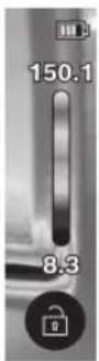
To determine the temperature of a given area, move the measuring device so that the crosshair with the temperature display (m) is aimed at the desired point or area. Automatic adjustment ensures a linear (= even) distribution of the color spectrum of the scale across the entire measuring range between the highest and lowest values.
The measuring device displays all measured temperatures in the measuring range in relation to each other. If, for example, heat is displayed in blue in a certain area on the color display, this means that the blue-colored spots represent cooler measured values of the current measuring range. However, these spots may still be in a temperature range that could lead to damage under certain conditions. For this reason, always consider the displayed temperature values on the scale or directly on the crosshair.
Functions
Observe the information on navigating through the various menus (see "Navigating through menus", page 289).

Illumination of the measuring object
The measuring device is equipped with a work light (4). It is intended for direct illumination of the working area of the measuring device for taking recordings and is not intended for use as a permanent work lamp.
To switch the work light on/off, open the left side bar. Navigate to the menu item / and confirm the selection. When the work light is on, this is indicated in the status bar.
The light automatically turns off after 2 minutes to prevent influence on measurements.
The time after which the light automatically turns off can be set in the menu.
Overlay of thermal and actual image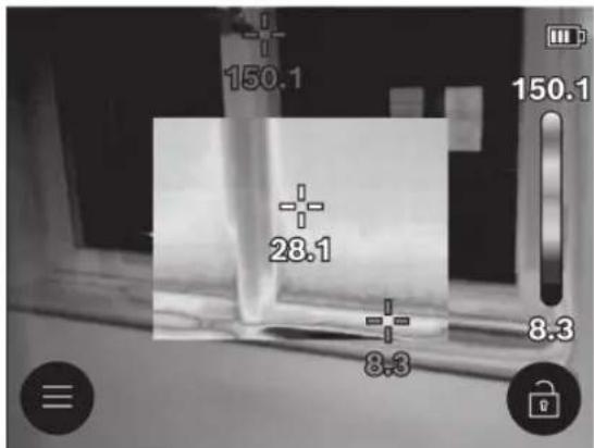
For better orientation (= placement of the displayed thermal image in space), the actual image can be added to the aligned temperature ranges.
Note: The overlay of the actual and thermal image is accurate at a distance of 1 m. At different distances from the measuring object, there may be a shift between the actual and thermal image. This shift can be compensated for with dedicated Bosch applications. Information about the applications and their compatibility is available on the measuring device page or at www.bosch-professional.com/thermal.
The measuring device offers the following options:
- 100% infrared image
Only the thermal image is displayed.

- Transparency
The displayed thermal image is slightly transparent and shown over the actual image. This makes it easier to identify objects.
To enable/disable this setting, open the left sidebar and navigate to the menu item / . Confirm the selection by pressing the center of the multi-function key (17).
- Picture-in-picture
The displayed thermal image is cut out, and the rest of the area is shown as the actual image. This setting makes it easier to position the measurement area in space.
To enable/disable this setting, open the left sidebar and navigate to the menu item / . Confirm the selection by pressing the center of the multi-function key (17).
Color display setting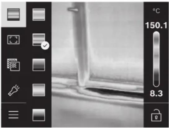
Depending on the measurement conditions, different color palettes can make it easier to analyze the thermal image and display objects and other states more clearly. This does not affect the measured temperatures. Only the display of temperature values changes.
To change the color palette, open the sidebar and navigate to the menu item "Color palette". Confirm the selection by pressing the center of the multi-function key (17).

Freezing the measurement scale
The colors are automatically distributed on the thermal image. You can freeze the distribution by pressing the multi-function key (17) to the right and then in the center. This allows you to compare thermal images taken under different thermal conditions (e.g., when checking multiple rooms for thermal bridges) or to remove an extremely cold or extremely hot object from the thermal image, as it would otherwise distort it (e.g., heating elements as hot objects when searching for thermal bridges).
To switch the scale back to automatic adjustment, open the right sidebar again and press the center of the multi-function key (17). The temperature distribution now runs dynamically again, as it adapts to the measured minimum and maximum values.
Main menu
Open the left sidebar (see "Navigating the menus", page 289). To enter the main menu, press the center of the multi-function key (17).
In this menu item, you can delete individual saved images or all saved images at once.
-
- (a)
For some of the most common materials, saved emissivities are available. To make searching easier, the values are grouped by category in the emissivity catalog. In the menu item, first select the appropriate category and then the appropriate material. If you know the exact emissivity value of the object being measured, you can also set it by entering the value in the menu item.
- (b)
Setting this parameter can improve the measurement result, especially for materials with low emissivity (= high reflectivity). Under some conditions (especially indoors), the reflected temperature corresponds to the ambient temperature. If objects with very different temperatures near reflective objects could affect the measurement, this value should be changed. Press the multi-function key (17) to the left or right.
-
To ensure high accuracy over the entire measurement range, the measurement is performed in two temperature ranges. During use of the measurement function, the measuring device automatically selects the appropriate temperature range based on the distribution of the measured temperature in the thermal image. It evaluates how many measured values are above a certain temperature threshold. If you measure very small but hot objects, the low temperature range may be automatically selected, which is not suitable for high temperatures. This is indicated by the symbol \~ before the value on the temperature display. In this case, select the measurement function <100 °C ... 450 °C> or <-20 °C ... 100 °C>, where the color distribution corresponds to the set temperature range. The setting is shown on the scale with an up or down arrow.
-
• (m): / The point is displayed in the center of the thermal image and shows the measured temperature at that location. - (n): / The hottest point (= measurement pixel) is marked on the thermal image as a red crosshair. This makes it easier to find critical spots (e.g., a loose contact terminal in a switch cabinet).
• (I): /
The coldest point (= measurement pixel) is marked on the thermal image as a blue crosshair. This makes it easier for you to find critical spots (e.g., leaks on a window).
- (i): /
- (c): /
The average temperature (°C) is displayed at the top left of the thermal image (the average temperature of all measured values on the thermal image). This can make it easier to determine the reflected temperature.
-
-
Under this menu item, you can adjust the screen brightness.
-
Under this menu item, you can select the time interval after which the work light automatically turns off if you do not press any button.
-
Under this menu item, you can select the time interval after which the measuring device automatically turns off if you
do not press any button. You can deactivate the automatic shutdown by selecting the setting .
-
In this submenu, in addition to setting the time and date, you can also change the format.
•
Under this menu item, you can select the language used on the display.
•
Under this menu item, you can reset the measuring device to factory settings and permanently delete all data. This may take a few minutes. Then press the multifunction button (17) to the right to delete all files or the multifunction button (17) to the left to cancel the process.
-
Under this menu item you can view information about the measuring device. Here you will find the serial number of the measuring device and the version of the installed software. In addition, you can view additional information about the measuring device here, as well as after a software update.
To exit any menu and switch to the standard display, you can also press the measurement button (6).
Updating the measuring device software
If necessary, you can update the measuring device software via the USB Type-C® interface. More information about this is available on the website:
www.bosch-professional.com/thermal-update.
Recording measurement results
Saving measurement results
After switching on, the measuring device starts measuring immediately. It only stops measuring when you switch the device off. To save an image, point the camera at the desired measurement object and press the measurement button (6). The image is saved in the internal memory of the measuring device. The measurement is frozen and the image is displayed on the screen. In this way, you can view the image at your leisure and adjust it afterwards (e.g., the color palette). If you do not want to save the frozen image, press the measurement button (6) to return to measurement mode. If you do want to save the image in the internal memory of the measuring device, press the center of the multi-function button (17).
Viewing saved images
You can access the saved thermal images as follows:
- Immediately after the image is saved, press the center of the multi-function button (17) once more. The preview of the last saved image is then displayed on the screen. – You can also view the saved images in the menu item .
- To scroll through the saved thermal images, press the multi-function button (17) to the right or left.
In addition to the thermal image, the actual image is also saved. To open it, press the multi-function button (17) up or down.
After 5 s, the full image opens on the measuring device. In this view, the title bar display is hidden so that you can see all the details of the thermal image.
To switch between views, press the multi-function button (17) up or down.
Deleting saved images
To delete individual or all thermal images, press the center of the multi-function button (17). A submenu opens.
- Here you can choose whether you want to delete only this image or all images. Confirm your selection by pressing the center of the multi-function button (17).
If you select , you can select or . Confirm your selection by pressing the center of the multi-function button (17).
- In this submenu, you can also view information about emissivity and reflected temperature.
File fragments of images remain in memory and can be reconstructed. For permanent deletion, select → in the main menu.
Data transfer
Data transfer via USB interface
Open the cover (11) of the USB Type-C® input. Connect the USB Type-C® socket (12) of the measuring device to your computer using the supplied USB Type-C® cable (16).
Switch on the measuring device with the on/off button (18).
Open the file explorer on your computer and select the drive GTC_450. You can copy, transfer to your computer, or delete the stored JPG files from the internal memory of the measuring device.
After the desired procedure, properly disconnect the drive from the computer and switch off the measuring device camera with the on/off button (18).
Caution: First remove the drive from the operating system (eject the drive), otherwise you could damage the internal memory of the measuring device.
Remove the USB Type-C® cable and close the cover (11).
Keep the USB connector cover closed at all times to prevent dust or water from entering the housing.
Note: Connect the measuring device via the USB interface only to a computer or laptop. Connecting the measuring device to other devices may damage it.
Note: The USB Type-C® interface is for data transfer only. It cannot be used to charge batteries or rechargeable batteries.
Processing thermal images
You can process saved thermal images with dedicated Bosch applications. Information about the applications and their compatibility is available on the measuring device page or at www.bosch-professional.com/thermal.
Errors – causes and assistance
In the event of a malfunction, the measuring device restarts automatically. It can then be used again. If this does not resolve the issue, refer to the table below for persistent error messages.
Error Cause Measures
| Merilne naprave ni mogoče vklopiti. | Izpraznjena akumulatorska baterija/navadne baterije | Napolnite akumulatorsko baterijo oz. zamenjajte baterije. | |
 | Napaka akumulatorske baterije/navadnih baterij | Menjava akumulatorskih baterij oz. baterij. | |
 | Akumulatorska baterija/ navadne baterije so prevroče oz. prehladne | Počakajte, da akumulatorska baterija doseže primerno temperaturo ali zamenjajte akumulatorsko baterijo/navadne baterije. | |
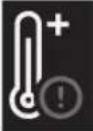 | Merilna naprava je pretopla oz. prehladna | Počakajte, da merilna naprava doseže primerno temperaturo. | |
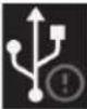 | Priključek USB ali kabel USB sta v okvari | Preverite, ali se lahko merilna naprava poveže s katerim drugim računalnikom. Če ne, pošljite merilno napravo pooblaščeni servisni službi Bosch.Opomba: vedno uporabljajte kabel USB, ki je priložen napravi. | |
| Merilne naprave ne morete povezati z računalnikom. | |||
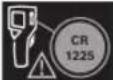 | Gumbna baterija je prazna Zamenjajte gumbno baterijo (glejte „Menjava gumbne baterije (glejte sliko C)“, Stran 294). Menjavo potrdite s pritiskom sredine večfunkcijske tipke (17). | ||
Explanation of terms
More information is available at www.bosch-professional.com/thermal.
Infrared thermal radiation
Infrared thermal radiation is electromagnetic radiation emitted by any body above 0 kelvin (-273 °C). The amount of radiation depends on the temperature and emissivity of the body.
Emissivity
The emissivity of a body depends on the material and structure of its surface. Emissivity indicates how much infrared thermal radiation a body emits compared to an ideal thermal radiator (black body, emissivity ε = 1) and represents a value between 0 and 1 accordingly.
Thermal bridge
A thermal bridge is a location on the exterior wall of a building where increased heat loss can occur due to the construction.
Thermal bridges can increase the risk of mold formation.
Reflected temperature/reflectivity of the object
Reflected temperature represents thermal radiation that does not originate from the object itself. Depending on the structure and type of material, environmental radiation is reflected from the object you want to measure, thus distorting the actual result.
Distance to the object
The distance between the measurement object and the measuring device affects the perceived size of the surface per image pixel. The greater the distance to the object, the larger the objects you can detect.
| Razdalja (m) Velikost infrardečih slikovnih točk (mm) | Širina × višina infrardečega območja (m) |
| 0,30 1,14 ~ 0,29 × 0,22 | |
| 0,55 2,08 ~ 0,53 × 0,40 | |
| 1,00 3,79 ~ 0,97 × 0,73 | |
| 2,00 7,58 ~ 1,94 × 1,46 | |
| 5,00 18,95 ~ 4,85 × 3,64 |
Maintenance and servicing
Maintenance and cleaning
Store and transport the measuring device only in suitable packaging, such as the original packaging.
The measuring device should always be clean. A dirty infrared sensor (5) can affect measurement accuracy.
During cleaning, liquids must not penetrate the measuring device. Do not remove dirt from the infrared sensor (5), camera (3), work light (4), or the laser beam exit opening (2) with pointed objects.
Do not wipe the infrared sensor and camera (risk of scratches).
Clean the surfaces around the laser exit opening especially regularly, and make sure the cloth does not leave lint.
If you want to recalibrate the measuring device, contact the Bosch service department.
Send the measuring tool for repair in its original packaging.
There are no parts in the measuring tool that can be repaired by the user. Opening the housing may damage the measuring tool.
Replacing the button battery (see figure C)
Open the cover (11).
Unscrew the screw (10) of the button battery holder. Pull the button battery holder (9) out of the measuring tool. Replace the button battery. After inserting the button battery holder, retighten the screw (10).
After-sales service and user advice
The service will answer your questions regarding repair and maintenance of the product as well as spare parts. Exploded views and information on spare parts can also be found online at: www.bosch-pt.com The Bosch user advice team will be happy to help you with questions about our products and their accessories.
When making any inquiries or ordering spare parts, please always quote the 10-digit number on the product's rating plate.
Robert Bosch d.o.o.
Verovškova 55a
1000 Ljubljana
Tel.: +00 803931
Fax: +00 803931
Mail: servis.pt@si.bosch.com
www.bosch.si
Other service addresses are listed under:
www.bosch-pt.com/serviceaddresses
Transport
The recommended lithium-ion batteries are subject to the requirements of dangerous goods legislation. The user can transport the batteries on the road without further conditions.
When shipping by third parties (e.g., air transport or freight forwarding), special requirements regarding packaging and labeling must be observed. When preparing the shipment, a hazardous materials expert must be involved.
Only ship batteries if the housing is undamaged. Tape over open contacts and pack the battery so that it does not move in the packaging. Please also observe any additional national regulations.
Disposal

Dispose of measuring devices, rechargeable/non-rechargeable batteries, accessories, and packaging in an environmentally friendly manner for recycling.
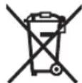
Do not dispose of measuring devices and rechargeable batteries/batteries in household waste!
Only for EU countries:
Used measuring devices and defective or spent rechargeable and non-rechargeable batteries must be collected and disposed of separately. Use the waste collection systems provided for this purpose.
In the event of improper disposal, waste electrical and electronic equipment may have harmful effects on the environment and human health due to the possible presence of hazardous substances.
Rechargeable batteries/batteries:
Lithium ions:
Follow the instructions in the "Transport" chapter (see "Transport", page 294).
Croatian
Safety Notes

Read all instructions and follow them to work safely and without danger with the measuring tool. If the measuring tool is not used in accordance with these instructions, this can
negatively affect the operation of the integrated protective devices in the measuring tool. The danger signs on the measuring tool must remain recognizable. KEEP THESE INSTRUCTIONS WELL AND HAND THEM OVER TO THE NEXT USER TOGETHER WITH THE MEASURING TOOL.
▶ Caution – If you use other devices for control or adjustment than those specified here or carry out other procedures, this can lead to dangerous exposure to radiation. The measuring tool is delivered with a laser danger sign (marked on the display of the measuring tool on the page with pictures). If the text on the laser danger sign is not in your native language, stick the supplied label in your native language over it before first use.
Do not point the laser beam at people or animals and do not look into the direct or reflected laser beam. This can blind people, cause accidents, or damage the eye.
If the laser beam hits the eye, consciously close your eyes and immediately move your head away from the beam.
▶ Do not make any modifications to the laser device. Do not use the laser viewing glasses (accessory) as protective goggles. Laser viewing glasses are used to better recognize the laser beam, but they do not protect against laser radiation. Do not use the laser viewing glasses (accessory) as sunglasses or in road traffic. Laser viewing glasses do not provide complete protection against UV radiation and reduce color recognition. ▶ Have the measuring tool repaired only by qualified specialist personnel and only with original spare parts. This will ensure that the safety of the measuring tool is maintained. ▶ Do not allow children to use the laser measuring tool without supervision. They could inadvertently blind other people or themselves. ▶ Do not work with the measuring tool in an environment endangered by explosion in which flammable liquids, gases, or dusts are present. Sparks may be generated in the measuring tool that could ignite dust or vapors. ▶ Do not modify or open the battery. There is a risk of short circuit. In the event of damage and improper use of the battery, vapors may be emitted. The battery may burn or explode. Provide fresh air and seek medical attention if necessary. Vapors may irritate the respiratory tract. In the event of incorrect use or a damaged battery, liquid may leak from the battery. Avoid contact with this liquid. In case of accidental contact, rinse the affected area with water. If this liquid gets into the eyes, seek medical attention. Leaked battery liquid can cause skin irritation or burns. ▶ The battery can be damaged by sharp objects such as nails, screwdrivers, or by external force. An internal short circuit may occur, and the battery may burn, develop smoke, explode, or overheat. Keep unused batteries away from paper clips, coins, keys, nails, screws, or other small metal objects that could bridge the contacts. A short circuit between the battery contacts can result in burns or fire. Use the battery only in products from the manufacturer. Only in this way is the battery protected against dangerous overload. Charge the battery only in chargers recommended by the manufacturer. A charger suitable for a specific type of battery poses a fire risk if used with another battery.


Protect the battery from heat, e.g., also from continuous sunlight, fire, dirt, water, and moisture. There is a risk of explosion and short circuit.

WARNING
Ensure that the button battery does not get into the hands of children. Button batteries are dangerous.
Button batteries must never be swallowed or inserted into other body openings. If there is any suspicion that a button battery has been swallowed or inserted into another body opening, seek medical attention immediately. Swallowing a button battery can cause serious internal burns and death within 2 hours. When replacing the button battery, ensure professional replacement. There is a risk of explosion. ▶ Use only the button batteries specified in these instructions for use. Do not use other button batteries or any other power supply. ▶ Do not attempt to recharge the button battery and do not short-circuit it. The button battery may leak, explode, burn, and cause injury. Properly remove and dispose of discharged button batteries. Discharged button batteries may leak and therefore damage the product or cause injury. ▶ Do not overheat the button battery or throw it into fire. The button battery may leak, explode, burn, and cause injury. ▶ Do not damage the button battery or disassemble it. The button battery may leak, explode, burn, and cause injury. Do not bring a damaged button battery into contact with water. The lithium that escapes can produce hydrogen with water, leading to fire, explosion, or personal injury. Do not continue to use the measuring tool if the button battery holder can no longer be closed properly and completely; remove the button battery and have the measuring tool repaired. ▶ Large temperature differences in the thermal image can cause only high temperatures to be displayed in one color, which are associated with low temperatures. Contact with such a surface can cause burns. Correct temperature measurement is only possible when the set emissivity and the emissivity of the object match. Objects could be displayed with too high or too low a temperature, which could pose a hazard upon contact. ▶ Do not point the measuring tool directly at the sun or a high-power CO₂ laser. This can cause damage to the detector. Protect the measuring tool, especially the camera areas and infrared lens, from moisture, snow, dust, and dirt. The receiving lens could fog up or become dirty and
affect the measurement results. Incorrect tool settings as well as other atmospheric factors can lead to inaccurate measurements. Objects could be displayed with too high or too low a temperature, which could pose a hazard upon contact.
Product description and specifications
Please refer to the images at the front of the operating manual.
Intended use
This thermal camera is intended for non-contact measurement of surface temperatures.
The displayed thermal image shows the temperature distribution of the thermal camera's field of view and thus allows different temperature deviations to be displayed in color.
In this way, with proper use, surfaces and objects can be inspected non-contact for temperature differences or temperature anomalies, in order to identify components and/or possible weak points, among other things:
- thermal insulation and insulation (e.g., finding thermal bridges)
- active heating and hot water pipes (e.g., underfloor heating) in floors and walls
- overheated electrical components (e.g., fuses or terminals)
- defective or damaged tool parts (e.g., overheating due to defective ball bearings).
The measuring tool is not suitable for measuring the temperature of gases.
The measuring tool must not be used for medical purposes. For information on use in veterinary medicine, visit www.bosch-professional.com/thermal.
The measuring tool is suitable for indoor and outdoor use.
This consumer laser product complies with EN 50689.
The light on the measuring tool is intended for direct illumination of the measuring tool's work area for image capture and is not intended as a permanent work light.
The laser point must not be used as a laser pointer.
It serves exclusively to mark the measuring surface.
Illustrated components
The numbering of the illustrated components refers to the illustration of the measuring tool on the graphics page.
(1) Protective cover (2) Laser beam outlet (3) Visual camera
(4) Work light (5) Infrared sensor (6) Pause/start measurement button (7) Battery compartment (8) Laser hazard symbol (9) Coin cell holder
(10) Coin cell holder screw (11) USB socket and coin cell holder cover (12) USB Type-C® socket a) (13) Laser button (14) Battery/adapter release button (15) Battery b) (16) USB Type-C® cable b) (17) Multi-function button (18) On/off/back button (19) Display (20) Serial number (21) Battery adapter case (22) Batteries b) (23) Battery adapter cover a) USB Type-C® and USB-C® are trademarks of USB Implementers Forum. b) Accessories shown or described are not included in the standard delivery.
Display elements
(a) Emission level display (b) Reflected temperature display (c) Average temperature display (d) Memory full symbol (e) Work light symbol (f) Laser symbol (g) Charge status indicator (h) Maximum surface temperature indicator in the measuring area
(i) Scale (j) Minimum surface temperature indicator in the measuring area (k) Temperature scale lock symbol (I) Cold spot indicator (as an example)
(m) Crosshair with temperature indicator
(n) Hot spot indicator (as an example) (o) Menu symbol
Technical data
Thermal camera GTC 12V-450-13
Catalogue number
3 601 K83 900
Thermal camera GTC 12V-450-13
| Rezolucija infracrvenog senzora 256 × 192 px | |
| Termička osjetljivost A) | ≤ 50 mK |
| Spektralno područje 8–14 μm | |
| Vidno polje (FOV) A) | 55,6° × 42° |
| Prostorna rezolucija (IFOV) 3,79 mrad | |
| Fokusna udaljenost A) | ≥ 0,5 m |
| Fokus fiksni | |
| Brzina osvježavanja termičke slike ≤ 9 Hz | |
| Mjerno područje površinske temperature A) | -20 ... +450 °C |
| Točnost mjerenja površinske temperature A)(B)(C) | |
| > 0 °C ... ≤ +100 °C D) | ±2 °C |
| > +100 °CE E) | ±2 % |
| Rezolucija temperature 0,1 °C | |
| Tip zaslona TFT | |
| Veličina zaslona 2,8" | |
| Rezolucija zaslona 480 × 360 px | |
| Rezolucija integrirane vizualne kamere 2 MP (640 × 480 px) | |
| Format slike .jpg | |
Stored elements per storage procedure 1 x thermal image (screen capture)
| 1 x vizualna stvarna slika uklj. vrijednosti temperature (metapodaci) | |
| Maks. broj slika u internoj memoriji slika 500 | |
| Maks. rad na visini iznad referentne visine 2000 m | |
| Stupanj onečišćenja sukladno normi IEC 61010-1 2 | F) |
| Relativna vlažnost zraka maks.A) | 90 % |
| Klasa lasera | 2 |
| Tip lasera | < 1 mW, 645–660 nm |
| Divergencija laserske zrake | 1,5 mrad (puni kut) |
| Napajanje | |
| - aku-baterija (litij-ionska) 12 V | |
| - baterije (alkalno-manganske s adapterom za baterije) | 4 × 1,5 V LR6 (AA) |
| - aku-baterije (NiMH s adapterom za baterije) | 4 × 1,2 V HR6 (AA) |
| Vrijeme radaG) | |
| - aku-baterija (litij-ionska)H) | 8 h |
| - baterije (alkalno-manganske) | 4 h |
| Napajanje, vrijeme sustava | CR1225 (3 V litijska baterija) |
| Standardni USB | 2.0 |
| USB sučelje | USB Type-C® |
| TežinaJ) | 0,354 kg |
| Dimenzije (duljina × širina × visina)K) | 89 × 79 × 209 mm |
| Vrsta zaštite (osim aku-baterije/baterija, u uspravnom položaju) | IP54 |
| Preporučena temperatura okoline kod punjenja | 0 °C ... +35 °C |
| Dopuštene temperature okoline | |
| - kod rada | -10 °C ... +50 °C |
298 | English
Thermal camera GTC 12V-450-13
| - kod skladištenja s aku-baterijom -20°C ... +50°C | |
| - kod skladištenja bez aku-baterije -20°C ... +70°C | |
| Preporučene aku-baterije GBA 12V... | |
| Preporučeni punjači GAL 12... | GAX 18... |
A) According to VDI 5585 (average value) B) At an ambient temperature of 20–23 °C and with an emissivity ≥ 0.95, measuring distance: 1 m, operating time: > 5 min, opening 150 mm, with work light and laser switched off C) Including application-dependent deviation (e.g., reflection, distance, ambient temperature) D) Applies to the center; for all other pixels add ±1 °C E) Applies to the center; for all other pixels add ±1 % F) Only non-conductive contamination occurs, with occasional transient conductivity caused by condensation. G) With work light switched off and medium screen brightness H) Depending on the battery inserted 1) At an ambient temperature of 20-30 °C J) Weight without battery/battery adapter/batteries K) With GBA 12V 2.0 Ah or battery adapter The serial number (20) on the rating plate serves to uniquely identify your measuring tool.
Power supply for the measuring tool
The measuring tool can operate with a Bosch lithium-ion battery, with conventional batteries, or with conventional NiMH rechargeable batteries.
Operation with rechargeable battery (see figure A)
▶ Use only the chargers listed in the technical data. Only these chargers are matched to the lithium-ion battery used in your measuring tool.
Note: Lithium-ion batteries are delivered partially charged due to international transport regulations. To ensure full battery performance, fully charge the battery before first use.
To insert the charged battery (15), push it into the battery compartment (7) until it audibly engages.
To remove the battery (15), press the release buttons (14) and pull the battery out of the battery compartment (7). Do not use force.
Operation with batteries (see figure B)
For operating the measuring tool, we recommend using alkaline-manganese batteries or NiMH rechargeable batteries.
The batteries are placed in the battery adapter.
The battery adapter is intended exclusively for use in designated Bosch measuring tools and must not be used with power tools.
To insert the batteries, push the sleeve (21) of the battery adapter into the battery compartment (7). Insert the batteries according to the illustration on the cover (23) into the sleeve. Push the cover over the sleeve until it audibly engages.
To remove the batteries (22), press the release buttons (14) on the cover (23) and remove the cover. Take out the batteries. To remove the sleeve (21), which is inside, from the battery compartment, grasp the sleeve and pull it out of the measuring tool with slight pressure on the side.
battery compartment, grasp the sleeve and pull it out of the measuring tool with slight pressure on the side.
Always replace all batteries or rechargeable batteries at the same time. Use only batteries or rechargeable batteries from a single manufacturer and of the same capacity.
Remove the batteries or rechargeable batteries from the measuring tool if it will not be used for an extended period. During prolonged storage, the batteries and rechargeable batteries may corrode in the measuring tool.
Notes for optimal handling of the rechargeable battery
Protect the rechargeable battery from moisture and water.
Store the rechargeable battery only in a room where the temperature range is between -20 °C and 50 °C. For example, do not leave the rechargeable battery in a car in summer.
A significantly shortened operating time after charging indicates that the rechargeable battery is worn out and must be replaced.
Follow the instructions for disposal.
Operation
Protect the measuring tool from moisture and direct sunlight.
Do not expose the measuring tool to extreme temperatures or temperature fluctuations. Do not leave it in a car for an extended period, for example. In the event of large temperature fluctuations, allow the measuring tool to acclimate before putting it into operation. Extreme temperatures or temperature fluctuations can negatively affect the accuracy of the measuring tool.
Ensure that the measuring tool is properly acclimatized. In the case of large temperature fluctuations, the acclimatization time can be up to 60 minutes. This can occur, for example,
if you store the measuring tool in a cold car and then take measurements in a warm building.
Avoid strong impacts and be careful not to drop the measuring device. After strong external influences or in the event of functional abnormalities, have the measuring tool checked by an authorized Bosch service center.
Start-up
At first switch-on
When first switching on the measuring tool or after resetting to factory settings, you need to set some basic settings. Select the desired values by pressing the multi-function button (17) down, up, left, or right. Press the multi-function button (17) in the center to confirm your selection. Once you have confirmed the selection, the next setting is displayed on the screen. The total number or the number of remaining settings is shown in the status bar at the top.
The following basic settings are available:
Switching on/off
For measuring, fold away the protective cap (1). During operation, ensure that the infrared sensor is not closed or covered.
To switch on the measuring tool, press the on/off button (18). The start sequence appears on the display (19). After the start sequence, the measuring tool immediately begins measuring and continues to do so until it is switched off.
Note: In the first few minutes, it may happen that the measuring tool adjusts itself more frequently because the sensor and ambient temperatures have not yet equalized. Recalibration of the sensor enables precise measurement.
During this time, the temperature indicator may be marked with \~. This effect is intensified in the case of large fluctuations in ambient temperature. Therefore, if possible, switch on the measuring tool a few minutes before starting measurement so that it can thermally stabilize.
To switch off the measuring tool, press the on/off button (18) for more than 1 second. The measuring tool stores all settings and then switches off. Close the protective cap (1) for safe transport of the measuring tool.
In the main menu, you can select whether and after what time the measuring tool should switch off automatically (see "Main menu", Page 301).
If the battery or the measuring tool is outside the operating temperature specified in the technical data, the measuring tool switches off automatically after a brief warning (see "Faults – causes and assistance", Page 303). Allow the measuring tool to acclimate and then switch it on again.
Navigating in the various menus
Navigating in the various menus of the measuring tool:
– Calling up the menu bars: Press the multi-function button (17) in the center or to the left. The menu bars on the right and left appear on the display, with the main menu highlighted.
- Scrolling in the left menu bar/navigating in the main menu: Press the multi-function button (17) up, down, left, or right.
- Switching between the left and right menu bars: Press the multi-function button (17) to the left or right.
- Confirm selection/switch to submenu: Press the multifunction button (17) in the center.
- Switch from submenu back to the next menu: Press the back button (18).
Preparation for measurement
Setting the emission level for surface temperature measurements
The emission level of an object depends on the material and structure of its surface. It indicates how much infrared radiation the object emits compared to an ideal thermal radiator (black body, emission level ε = 1) and therefore has a value between 0 and 1.
To determine surface temperature, the natural infrared radiation emitted by the target object is measured without contact. For correct measurement, you must check the emission level set on the measuring tool before each measurement and adjust it to the measuring object if necessary.
The preset emission levels in the measuring tool serve as a guide.
You can select one of the preset emission levels or enter an exact numerical value. Set the desired emission level via the menu → (see "Main menu", Page 301).
▶ Correct temperature measurement is only possible when the set emission level and the emission level of the object match.
The lower the emission level, the greater the influence of reflected temperature on the measurement result. Therefore, when changing the emission level, always adjust the reflected temperature. Set the reflected temperature via the menu → (see "Main menu", Page 301).
Temperature differences that the measuring tool may display can be attributed to different temperatures and/or different emission levels. In the case of very different emission levels, the displayed temperature differences can deviate significantly from the actual ones.
If multiple measuring objects of different materials or structures are in the measuring range, then the displayed temperature values are only accurate for objects that match the set emission level. For all other objects (with different emission levels), the
displayed color differences can be used as an indicator of temperature conditions.
Notes on measurement conditions
Reflective or shiny surfaces (e.g., shiny tiles or polished metals) can significantly affect the displayed results. If necessary, cover the measuring surface with a dark, matte adhesive tape that conducts heat well. Leave the tape on the surface briefly to allow it to acclimate.
With reflective surfaces, ensure you have a favorable measurement angle so that reflected thermal radiation from other objects does not degrade the result. For example, when measuring vertically from the front, reflection of your body heat can affect the measurement. On a flat surface, outlines and temperature of your body (reflected value) may be displayed, which do not correspond to the actual temperature of the measuring surface (emitted value, i.e., actual surface value).
Measurement through transparent materials (e.g., glass or transparent plastic) is generally not possible.
Measurement results will be more accurate and reliable the better and more stable the measurement conditions are. Not only large temperature fluctuations in the ambient conditions are relevant, but even large temperature fluctuations of the measured object can affect accuracy.
Infrared temperature measurement is affected by smoke, steam/high humidity, or dust in the air.
Instructions for better measurement accuracy:
– Approach the measurement object as closely as possible to reduce interfering factors between you and the measuring surface. - Before measuring, ventilate indoor rooms, especially if the air is dirty or full of steam. After ventilating, temper the room until the usual temperature is reached again.
Marking the measurement spot
▶ Do not point the laser beam at people or animals and do not look directly into the laser beam, even from a distance.
The measuring tool has a laser for marking the measurement spot. Press and hold the laser button (13). The laser symbol (f) appears in the status bar and a red circle appears around the crosshair (m). The laser and crosshair overlap exactly at a distance of 1 m. When you release the laser button (13), the laser switches off.
Assigning temperatures using the scale
A scale (i) is displayed on the right side of the screen. The values at the top and bottom ends are oriented to the maximum temperature (h) and minimum temperature (j) registered in the thermal image. The scale evaluates 99.99% of the pixels. The assignment of a color to a temperature value in the image is evenly distributed (linear).
Using different color shades, temperatures can be assigned within these two limit values. For example, the temperature exactly between the maximum and minimum values is assigned to the middle color range on the scale.
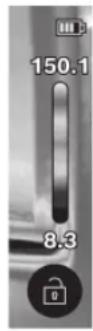
To determine the temperature of a specific area, move the measuring tool so that the crosshair with the temperature indicator (m) is aimed at the desired point or area. With automatic adjustment, the color spectrum on the scale is always distributed linearly (= evenly) over the entire measuring range within the maximum and minimum temperatures.
The measuring tool displays all measured temperatures in the measuring range in relation to each other. If, in a certain area, for example in the color display, heat is shown in a color palette in a bluish color, this means that the bluish areas belong to colder measured values in the current measuring range. These areas can also be in a temperature range that, depending on the circumstances, can cause injuries. Therefore, always pay attention to the displayed temperatures on the scale or directly on the crosshair.
Functions
Follow the information on navigating through the various menus (see "Navigating through the various menus", page 299)

Illumination of the measuring object
The measuring tool has a work light (4). It is intended for direct illumination of the working area of the measuring tool for capturing images and is not intended as a permanent work light.
To switch the work light on/off, call up the left side bar. Scroll to the menu item // and confirm the selection. When the work light is switched on, this is shown in the status bar.
The light switches off automatically after 2 minutes so that it does not affect the accuracy of the measurement.
You can set the automatic switch-off time in the menu under .
Overlay of thermal and real image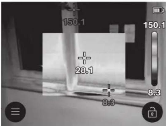
For better orientation (= spatial assignment of the displayed thermal image), a visual real image can be additionally switched on for equalized temperature areas.
Note: The overlay of the real and thermal image is accurate at a distance of 1 m. If the distance to the measuring object deviates, there may be deviations between the real and thermal image. This deviation can be compensated for using special Bosch apps. Information about the apps and their compatibility can be found on the product page of the measuring tool or on the website www.bosch-professional.com/thermal.
The measuring tool offers you the following options:
- 100% infrared image
Only the thermal image is displayed.

- Transparency
The displayed thermal image is set to be slightly transparent over the real image. This way, objects can be better recognized.
To activate/deactivate the setting, call up the left side bar and scroll to the menu item / . Confirm the selection by pressing the multi-function key (17) in the center.
- Picture-in-picture
The displayed thermal image is cropped, and the surrounding area is shown as a real image. This setting improves the local assignment of the measurement area.
To activate/deactivate the setting, call up the left side bar and scroll to the menu item / . Confirm the selection by pressing the multi-function key (17) in the center.
Adjusting the color display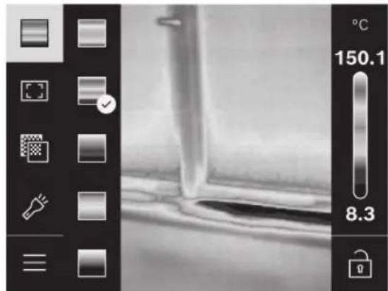
Depending on the measurement situation, different color palettes can facilitate the analysis of the thermal image and display objects or actual conditions more clearly on the screen. This does not affect the measured temperatures. Only the display of temperature values changes.
To change the color palette, call up the side bar and scroll to the menu item "Color palette". Confirm the selection by pressing the multi-function key (17) in the center.

Fixing the scale
The adjustment of the color distribution on the thermal image is done automatically, but it can also be fixed by pressing the multi-function key (17) to the right and then in the center. This enables the possibility of comparing thermal images taken under different temperature conditions (e.g., when checking the consistency of thermal bridges in multiple rooms) or hiding an extremely cold or hot object on the thermal image that would otherwise distort it (e.g., radiators as hot objects when testing thermal bridges).
To switch the scale back to automatic, call up the right side bar and press the multi-function key (17) in the center. The temperatures now behave dynamically again and adapt to the measured minimum and maximum values.
Main menu
Call up the left side bar (see "Navigating in different menus", Page 299). To get to the main menu, press the multi-function key (17) in the center.
- Under this menu item, you can delete individual or all saved images at the same time.
-
- (a)
For some of the most common materials, you can select stored emissivity levels. To make searching easier, the values are grouped in a table of emissivity levels. First, in the menu item <Material catalog>, select the appropriate category and then the material. If you know the exact emissivity level of your measuring object, you can also set it as a numerical value in the menu item.
material catalog> select the appropriate category and then the material. If you know the exact emissivity level of your measuring object, you can also set it as a numerical value in the menu item.
numerical value in the menu item.
• (b)
Setting this parameter can improve the measurement result, especially for materials with low emissivity (= high reflectivity). In some situations (especially indoors), the reflected temperature corresponds to the ambient temperature. If objects with strongly deviating temperatures nearby can influence the measurement of highly reflective objects, you should adjust this value. To do this, press the multi-function button (17) left or right.
-
To ensure high accuracy over the entire measuring range, measurement is performed in 2 temperature ranges. In the measurement function, the measuring tool automatically selects the appropriate temperature range based on the temperature distribution in the thermal image. It assesses how many measured values are above a certain temperature threshold. If you need to measure very small but hot objects, the selection of a low temperature range that is not suitable for high temperatures may occur. This can be recognized by the symbol \~ placed in front of the temperature display. In that case, switch to the measurement function
<100 °C ... 450 °C> or <-20 °C ... 100 °C> in which the color distribution corresponds to the set temperature range. The setting is indicated by an arrow up or down on the scale.
-
- (m): / The point is displayed in the center of the thermal image and shows you the measured temperature value at that location.
- (n): / The hottest point (= measuring pixel) is marked with a red crosshair on the thermal image. This makes it easier to find critical spots (e.g., loose contact terminal in a switch cabinet).
- (I): / The coldest point (= measuring pixel) is marked with a blue crosshair on the thermal image. This makes it easier to find critical spots (e.g., leak in a window). • (i): /
- (c): / The average temperature (c) is displayed at the top left of the thermal image (average temperature of all measured values in the thermal image). This can make it easier for you to determine the reflected temperature.
-
- Under this menu item, you can adjust the screen brightness.
- Under this menu item, you can select the time interval for automatic shutdown of the work light if no button is pressed.
- Under this menu item, you can select the time interval after which the measuring tool should
automatically switch off if no button is pressed. You can deactivate automatic shutdown by selecting the setting .
-
In addition to the time and date settings, you can also change their formats in this submenu.
-
Under this menu item, you can select the language used on the display.
•
Under this menu item, you can reset the measuring tool to factory settings and permanently delete all data. This may take several minutes depending on the circumstances. Press the multi-function button (17) on the right to delete all files, or the multi-function button (17) on the left to cancel the process.
-
Under this menu item, you can access information about the measuring tool. There you will find the serial number of the measuring tool and the installed software version. In addition, you can find further information about the measuring tool and software updates there.
To exit any menu and return to the standard display screen, you can also press the measurement button (6).
Software update for the measuring tool
If necessary, you can update the software of the measuring tool via the USB Type-C® interface. You will find information on the website:
www.bosch-professional.com/thermal-update.
Documentation of measurement results
Saving measurement results
Immediately after switching on, the measuring tool starts measuring and continues to do so until it is switched off.
To save an image, point the camera at the desired measuring object and press the measurement button (6). The image is stored in the internal memory of the measuring tool. The measurement is frozen and displayed on the screen. This allows you to carefully observe the image and adjust it afterwards (e.g., color palette). If you do not want to save the frozen image, press the measurement button (6) again to restart the measurement mode. If you want to store the image in the internal memory of the measuring tool, press the multifunction button (17) in the middle.
Calling up saved images
To call up saved thermal images, proceed as follows:
- Immediately after saving, press the multifunction button (17) in the middle again. The preview image of the last saved image now appears on the screen.
- Alternatively, you can retrieve saved images under the menu item .
- To switch between saved thermal images, press the multifunction button (17) to the right or left.
In addition to the thermal image, a visual image is also saved. To call it up, press the multifunction button (17) up or down.
After 5 seconds, the measuring tool switches to full-screen image display. In full-screen image display, the title bar display will be hidden so that you can observe all details in the thermal image.
By pressing the multifunction button (17) up and down, you can change the displays.
Deleting saved images
To delete individual or all thermal images, press the multifunction button (17) in the middle. A submenu opens.
- Here you can choose whether you want to delete only this image or all images. Confirm your selection by pressing the multifunction button (17) in the middle.
If you select , you can choose between and . Confirm your selection by pressing the multifunction button (17) in the middle.
- In this submenu, you can also view information about the emission level and the reflected temperature.
Image data fragments remain in memory and could be reconstructed. For permanent deletion, select in the main menu → .
Data transfer
Data transfer via USB interface
Open the cover (11) of the USB Type-C® socket. Connect the USB Type-C® socket (12) of the measuring tool to your computer using the supplied USB Type-C® cable (16).
Now switch on the measuring tool by pressing the on/off button (18).
On your computer, open the file browser and select the drive GTC_450. The stored files can be copied, transferred to the computer, or deleted from the internal memory of the measuring tool.
When you have completed the desired procedure, properly disconnect the drive from the computer and then switch off the measuring tool again by pressing the on/off button (18).
Caution: Always eject the drive from your operating system first (eject the drive), otherwise the internal memory of the measuring tool may be damaged.
Remove the USB Type-C® cable and close the cover (11). Always keep the USB interface cover closed to prevent dust or water droplets from entering the housing.
Note: Connect the measuring tool to a computer only via the USB cable. When connecting to other devices, the measuring tool may be damaged.
Note: The USB Type-C® interface is intended exclusively for data transfer. Batteries and rechargeable batteries cannot be charged via the interface.
Final processing of thermal images
You can post-process the saved thermal images using special Bosch applications. Information about the applications and their compatibility can be found on the product page of the measuring tool or on the website www.bosch-professional.com/thermal.
Interference - causes and assistance
In the event of interference, the measuring tool performs a restart and can be used again immediately afterwards. Otherwise, the following overview of persistent error messages will help you.
Interference Cause Assistance
| Mjerni alat ne može se uključiti. | Aku-baterija je prazna/baterije su prazne | Napunite aku-bateriju odn. zamijenite baterije. | |
 | Pogreška aku-baterije/baterija | Zamijenite aku-bateriju odn. baterije. | |
| Aku-baterija/baterije previše tople ili previše hladne | Ostavite aku-bateriju da se temperira ili zamijenite aku-bateriju ili baterije. | |
| Mjerni alat previše topao ili previše hladan | Ostavite mjerni alat da se temperira. | |
| USB priključak ili USB kabel je neispravan | Provjerite može li se mjerni alat povezati s nekim drugim računalom. Ako ne može, pošaljite mjerni alat u ovlašteni Bosch servis.Napomena:Uvijek upotrebljavajte USB kabel iz opsega isporuke. | |
| Mjerni alat se ne može povezati s računalom. | |||
Interference Cause Assistance
Empty button battery Replace the button battery (see "Replacing the button
battery (see Figure C)", page 304). Confirm the replacement by selecting "OK" with the multi-function button (17) in the center.
Explanation of terms
Additional information can be found on the website www.bosch-professional.com/thermal.
Infrared radiation
Infrared radiation is electromagnetic radiation emitted by every body above 0 kelvin (-273 °C). The amount of radiation depends on the temperature and the degree of emission of the body.
Degree of emission
The degree of emission of an object depends on the material and structure of its surface. It indicates how much infrared radiation the object emits compared to an ideal thermal radiator (black body, degree of emission ε = 1) and therefore has a value between 0 and 1.
Thermal bridge
A thermal bridge is a location on the exterior wall of a building where locally increased heat loss occurs through the structure.
Thermal bridges can cause an increased risk of mold.
Reflected temperature/reflectivity of an object
Reflected temperature is the radiation of thermal rays that do not come from the object itself. Depending on the structure and material, ambient radiation is reflected in the object to be measured and thus influences the actual temperature result.
Distance to the object
The distance between the measuring object and the measuring tool affects the registered surface size per pixel. With a greater distance to the object, you can register large objects.
| Udaljenost (m) Veličina infracrvenog piksela (mm) | Širina × visina infracrvenog područja (m) |
| 0,30 1,14 ~ 0,29 × 0,22 | |
| 0,55 2,08 ~ 0,53 × 0,40 | |
| 1,00 3,79 ~ 0,97 × 0,73 | |
| 2,00 7,58 ~ 1,94 × 1,46 | |
| 5,00 18,95 ~ 4,85 × 3,64 |
Maintenance and servicing
Maintenance and cleaning
Store and transport the measuring tool only in a suitable box, such as the original packaging.
Always keep the measuring tool clean. A dirty infrared sensor (5) can affect measurement accuracy.
When cleaning, liquid must not penetrate the measuring tool.
Do not attempt to remove dirt from the infrared sensor (5), camera (3), work light (4), or the laser beam outlet (2) with a pointed object. Do not wipe across the infrared sensor and camera (risk of scratches).
Clean the surfaces at the laser outlet regularly, paying attention to fibers.
If you wish to recalibrate the measuring tool, contact an authorized Bosch service center.
In case of repair, send the measuring tool in its original packaging.
The measuring tool contains no parts that require maintenance. Opening the housing cover can destroy the measuring tool.
Replacing the button battery (see figure C)
Open the cover (11).
Unscrew the screw (10) for the button battery holder. Pull the button battery holder (9) out of the measuring tool. Replace the button battery. Retighten the screw (10) after inserting the button battery holder.
After-sales service and usage advice
The after-sales service will answer all your questions about repairing and maintaining this product and about spare parts. Enlarged drawings and information about spare parts can also be found at: www.bosch-pt.com
The Bosch application consulting team will be happy to help you with all questions about our products and their accessories.
For all questions and spare parts orders, please always specify the 10-digit article number given on the rating plate.
Croatian
Robert Bosch d.o.o PT/SHR-BSC
Kneza Branimira 22
10040 Zagreb
Tel.: +385 12 958 051
Fax: +385 12 958 050
E-Mail: RBKN-bsc@hr.bosch.com
www.bosch.hr
Additional service addresses can be found at:
www.bosch-pt.com/serviceaddresses
Transport
The recommended lithium-ion batteries are subject to the requirements of the law on dangerous goods. The user can transport the batteries by road without additional conditions.
When sending via intermediaries (e.g., air transport or freight forwarder), special requirements for
packaging and labeling must be observed. In this case, a dangerous goods expert must be consulted when preparing the shipment. Only send batteries if the housing is not damaged. Tape off open contacts and pack the battery so that it cannot move in the packaging. Please also observe any additional national regulations.
Disposal

Measuring tools, rechargeable batteries/batteries, accessories, and packaging should be brought to environmentally friendly recycling.
Do not dispose of measuring tools and rechargeable batteries/batteries in household waste!
Only for EU countries:
Unusable measuring tools and defective or worn-out rechargeable batteries/batteries must be disposed of separately. Use the designated waste collection systems.
If waste electrical and electronic equipment is disposed of improperly, it can have harmful effects on the environment and human health due to the possible presence of hazardous substances.
Rechargeable batteries/batteries:
Lithium-ion:
Observe the instructions in the Transport chapter (see "Transport", Page 304).
Estonian
Safety instructions

To ensure safe and accurate work with the measuring tool, read all instructions carefully and follow them. If these instructions are disregarded when using the measuring tool, the protective devices built into the measuring tool may be damaged. Do not cover the warning labels on the measuring tool. KEEP THESE INSTRUCTIONS CAREFULLY AND INCLUDE THEM WITH THE MEASURING TOOL WHEN PASSING IT ON.
▶ Caution – the use of operating or adjustment equipment other than that specified in this manual, or the use of other procedures, may result in hazardous laser radiation. The measuring tool is supplied with a laser warning label (marked on the illustration of the tool on the graphics page). If the text on the laser warning label is not in the language spoken in your country, affix the enclosed label in your national language over it before the first use of the tool.
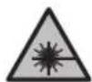
Do not direct the laser beam at people or animals, and do not look into the direct or reflected laser beam yourself. Otherwise, you may blind people, cause accidents, or damage eyes.
If the laser beam hits the eye, consciously close the eyes and immediately move the head out of the laser beam plane. - Do not make any modifications to the laser device. - Do not use glasses that improve the visibility of the laser beam (accessories) as protective glasses. These glasses make the laser beam more visible but do not protect against laser radiation. - Do not use glasses that improve the visibility of the laser beam (accessories) as sunglasses or while driving. Glasses that improve the visibility of the laser beam do not provide full protection against UV radiation and reduce the ability to distinguish colors. Have the measuring tool repaired only by qualified technicians using original spare parts. This ensures the safe operation of the measuring tool. - Do not allow children to use the laser measuring tool without supervision. Children may accidentally blind other people or themselves. - Do not operate the measuring tool in explosive environments where flammable liquids, gases, or dust are present. Sparks may be generated in the measuring tool, which can ignite dust or fumes. - Do not modify or open the battery. There is a risk of short-circuiting. If the battery is damaged or handled improperly, vapors may be released from the battery. The battery may catch fire or explode. Ventilate the room, and if you feel unwell, consult a doctor. Vapors may irritate the respiratory tract. In case of misuse or a damaged battery, flammable liquid may leak out. Avoid contact with it. In case of accidental contact, rinse with water. If the liquid gets into the eyes, also consult a doctor. Leaking battery fluid may cause skin irritation or burns. ▶ Sharp objects such as nails or screwdrivers, as well as impacts, knocks, etc., can damage the battery. A short circuit may occur between the battery contacts, and the battery may catch fire, start smoking, explode, or overheat. When not in use, keep batteries away from paper clips, coins, keys, nails, screws, or other small metal objects that could connect the contacts. A short circuit between the battery contacts can result in burns or fire. ▶ Use the battery only in products from the manufacturer. Only in this way is the battery protected against dangerous overload. ▶ Charge batteries only with chargers recommended by the manufacturer. A charger that is suitable for a certain type of battery may become a fire hazard if used with other batteries.
Protect the battery from heat, including continuous sunlight, as well as fire, dirt, water, and moisture. Risk of explosion and short-circuit.


WARNING


Ensure that button cells are kept out of the reach of children. Button cells are dangerous.
Button cells must never be swallowed or inserted into other body orifices. If there is any suspicion that a button cell has been swallowed or has entered another body cavity, seek medical attention immediately. Swallowing a button cell can cause severe internal burns within 2 hours and can be fatal. When replacing button cells, pay attention to correct replacement. There is a risk of explosion. - Use only the button cells specified in these instructions. Do not use other button cells or other power sources. - Do not attempt to recharge the button cell and protect it from short circuits. The button cell may leak, explode, cause burns, and personal injury. Remove and dispose of empty button cells properly. Empty button cells may leak, which can damage the device and cause personal injury. - Do not heat the button cell or throw it into fire. The button cell may leak, explode, cause burns, and personal injury. - Do not damage the button cell or take it apart. The button cell may leak, explode, cause burns, and personal injury. Prevent contact of a damaged button cell with water. If released lithium comes into contact with water, hydrogen may be produced, which can lead to fire, explosion, or personal injury. - Do not use the measuring tool if the button cell compartment can no longer be closed properly and completely; remove the button cell and have the measuring tool repaired. Large temperature differences in the thermal image can cause high temperatures to be displayed with a color that is usually associated with low temperatures. Contact with such a surface can cause burns. Correct temperature measurements are only possible if the set emissivity and the object's emissivity are the same. Objects may be displayed with temperatures that are too high or too low, which can be dangerous when touched.
- Do not point the measuring device directly at the sun or at a high-power CO₂ laser. This can damage the sensor. Protect the measuring tool, especially the camera and infrared lens areas, from moisture, snow, dust, and dirt. The receiving lens can fog up or become dirty and distort measurement results. Incorrect device settings and various atmospheric factors can cause incorrect measurements. Objects may be displayed with temperatures that are too high or too low, which can be dangerous when touched.
Product description and instructions for use
Follow the figures in the front section of the instructions for use.
Intended use
This thermal camera is intended for non-contact measurement of surface temperatures.
The displayed thermal image shows the temperature distribution in the thermal camera's field of view and thus allows temperature differences to be visualized in color.
With correct use, temperature differences and characteristics of surfaces and objects can be identified without contact, and components and/or weak points can be detected, including:
- insulation and thermal insulation (e.g., finding thermal bridges),
- Active heating and hot water pipes (e.g., underfloor heating) in floors and walls,
- Overheated electrical components (e.g., fuses or terminals),
- Defective or damaged machine parts (e.g., overheating due to defective ball bearings).
The measuring tool is not suitable for measuring the temperature of gases.
This measuring tool must not be used for the purpose of providing medical assistance to people.
For veterinary medical use, see www.bosch-professional.com/thermal.
The measuring tool is suitable for indoor and outdoor use.
This product is a consumer laser product that complies with EN 50689.
The measuring tool's light is intended for illuminating the direct work area of the measuring tool for taking pictures and is not intended for permanent work lighting.
The laser point must not be used to point at anything. It is intended solely for marking the area to be measured.
Illustrated components
The numbering of the illustrated components is based on the numbers shown on the illustration page.
(1) Protective cap (2) Laser beam exit opening (3) Visual camera (4) Work light (5) Infrared sensor (6) Measurement pause/start button
(7) Battery compartment
(8) Laser warning label
(9) Battery compartment cover
(10) Battery compartment cover screw
(11) USB port and battery compartment cover
(12) USB Type-C ® port a)
(13) Laser button
(14) Battery/adapter release button
(15) Battery b
(16) USB Type-C ® cable b)
(17) Multi-function button
(18) On/off button/back button
(19) Display
(20) Serial number
(21) Battery adapter housing
(22) Batteries b)
(23) Battery adapter cap
a) USB Type-C® and USB-C® are trademarks of USB Implementers Forum.
b) The delivery package does not include all accessories shown in the figures or mentioned in the operating instructions.
Display elements
(a) Emissivity indicator (b) Reflected temperature indicator (c) Average temperature indicator (d) Symbol "memory full" (e) Symbol "work light" (f) Symbol "laser" (g) Charge level indicator (h) Maximum surface temperature indicator in the measuring range (i) Scale (j) Minimum surface temperature indicator in the measuring range (k) Temperature scale locking symbol (I) Cold spot indicator (example)
(m) Crosshair with temperature display
(n) Hot spot indicator (example)
(o) Symbol "menu"
Technical data
| Termokaamera GTC 12V-450-13 | |
| Tootenumber | 3 601 K83 900 |
| Infrapunaanduri eraldusvõime 256 × 192 px | |
| Termiline tundlikkus A) | ≤ 50 mK |
| Spektraalvahemik 8–14 μm | |
| Vaateväli (FOV) A) | 55,6° × 42° |
| Ruumiline eraldusvõime (IFOV) 3,79 mrad | |
| Fookuskaugus A) | ≥ 0,5 m |
| Fookus fix | |
| Termopildi värskendussagedus ≤ 9 Hz | |
| Pinnatemperatuuri mõõtevahemik A) | -20 ... +450 °C |
| Pinnatemperatuuri mõõtetäpsus A)(B)(C) | |
| >0 °C ... ≤ +100 °C D) | ±2 °C |
| >+100 °C E) | ±2% |
| Temperatuuri eraldusvõime 0,1 °C | |
| Ekraani tüüp TFT | |
| Ekraani suurus 2,8" | |
| Ekraani eraldusvõime 480 × 360 px | |
| Integreeritud visuaalse kaamera eraldusvõime 2 MP (640 × 480 px) | |
| Pildi vorming .jpg | |
| Salvestatud elemente ühe salvestustoimingu kohta 1 × termopilt (kuvatõmmis),1 × visuaalne reaalaja pilt koos temperatuuriväärtustega (metaandmetega) | |
308 | English
Thermal camera GTC 12V-450-13
| Piltide max arv sisemises pildimälus 500 | |
| Maksimaalne kontrollkõrgust ületav töökõrgus 2000 m | |
| Määrdumisaste vastavalt standardile IEC 61010-1 2 | r) |
| Max suhteline õhuniiskusA) | 90% |
| Laseri klass 2 | |
| Laseri tüüp < 1 mW, 645–660 nm | |
| Laserikiire hajumine 1,5 mrad (täispööre) | |
| Energiavarustus | |
| - Aku (liitium-ioon) 12 V | |
| - Patareid (leelis-mangaan, patareiadapteriga) 4 × 1,5 V LR6 (AA) | |
| - Akud (NiMH, patareiadapteriga) 4 × 1,2 V HR6 (AA) | |
| TööaegG) | |
| - Aku (liitium-ioon) H) | 8 h |
| - Patareid (leelis-mangaan) 4 h | |
| Süsteemiaja toide CR1225 (3 V liitiumpatarei) | |
| USB-standard 2.0 | |
| USB liides USB Type-C® | |
| KaalJ) | 0,354 kg |
| Mõõtmed (pikkus × laius × kõrgus)K) | 89 × 79 × 209 mm |
| Kaitseaste (v.a aku/patareid, püstiasendis) IP54 | |
| Soovitatav keskkonnatemperatuur laadimisel 0 °C ... +35 °C | |
| Lubatud keskkonnatemperatuur | |
| - töötamisel | -10 °C ... +50 °C |
| - ladustamisel koos akuga | -20 °C ... +50 °C |
| - ladustamisel ilma akuta | -20 °C ... +70 °C |
| Soovitatavad akud | GBA 12V... |
| Soovitatavad laadimisseadmed | GAL 12...GAX 18... |
A) In accordance with VDI 5585 (average value)
B) At ambient temperature 20–23°C and emissivity ≥ 0.95, measuring distance: 1 m, operating time: > 5 min, aperture size 150 mm, with work light and laser switched off
C) With deviation due to usage conditions (e.g., reflection, distance, ambient temperature)
D) Applies to the center point; for all other pixels, add ±1 °C
E) Applies to the center point; for all other pixels, add ±1%
F) Only non-conductive contamination is present, which may, however, become temporarily conductive due to condensation.
G) With the work light switched off and medium screen brightness
H) depending on the battery used
I) at an ambient temperature of 20-30°C
J) Weight without battery/battery adapter/batteries
K) with GBA 12V 2.0Ah or battery adapter
The serial number (20) on the type plate is used for unique identification of your measuring tool.
Power supply for the measuring tool
The measuring tool can be operated with a Bosch lithium-ion battery, standard batteries, or standard NiMH batteries.
Operation with battery (see figure A)
▶ Use only the charging devices specified in the technical data. Only these charging devices are intended for charging the Li-ion battery used in your measuring tool.
Note: Lithium-ion batteries are supplied partially charged from the factory in accordance with international transport regulations. To ensure full battery capacity, fully charge the battery before first use.
To insert, push the charged battery (15) into the battery compartment (7) until it audibly locks into place.
To remove the battery (15), press the release buttons (14) and pull the battery out of the battery compartment (7).
Do not use force when doing so.
Using batteries (see figure B)
It is recommended to use alkaline manganese batteries or NiMH rechargeable batteries in the measuring tool. The batteries are placed in the battery adapter.
▶ The battery adapter is intended for use only in the specified Bosch measuring tools; it must not be used in power tools.
To insert the batteries, push the battery adapter sleeve (21) into the battery compartment (7). Place the batteries in the sleeve according to the illustration on the cap (23). Push the cap onto the sleeve until it audibly engages. To remove the batteries (22), press the release buttons (14) on the cap (23) and pull the cap off. Remove the batteries. To remove the sleeve (21) from the battery compartment, grasp the sleeve and pull it out of the measuring tool while gently pressing it against the side wall. Always replace all batteries or rechargeable batteries at the same time. Use only batteries or rechargeable batteries from one manufacturer and with the same capacity.
If you do not use the measuring tool for a longer period, remove the batteries or rechargeable batteries. Batteries and rechargeable batteries can corrode if left in the measuring tool for a long time.
Instructions for handling the rechargeable battery
Protect the rechargeable battery from moisture and water.
Store the rechargeable battery at temperatures between -20 °C and 50 °C. Do not leave the rechargeable battery in a car in summer.
A significantly shortened operating time after charging indicates that the rechargeable battery is no longer usable and must be replaced. Follow the recycling instructions.
Operation
- Protect the measuring tool from moisture and direct sunlight.
- Do not expose the measuring tool to extreme temperatures or temperature fluctuations. Do not leave it in a car for extended periods, for example. In case of large temperature fluctuations, allow the measuring tool to adapt to the ambient temperature before use. Extreme temperatures or temperature fluctuations can reduce the accuracy of the measuring tool. ▶ Ensure that the measuring tool has adapted to the ambient temperature. If the temperature fluctuates significantly, the adaptation time can be up to 60 minutes. This can happen, for example, when
you keep the measuring tool in a cold car and then take measurements in a warm room.
Avoid strong impacts on the measuring tool and dropping it. After strong external influences and if the device operates abnormally, the measuring tool should be checked at an authorized Bosch customer service center.
Initial operation
On first switching on
When switching on the measuring tool for the first time or after resetting it to factory settings, some basic settings must be made. Select the desired values by pressing the multi-function button (17) up, down, left, or right. Press the center of the multi-function button (17) to confirm your selection. As soon as you have confirmed a selection, the next setting is displayed on the screen. The total number and the number of remaining settings are shown in the upper status bar.
The following basic settings are available:
-
Switching on/off
For measuring, fold open the protective cap (1). During operation, ensure that the infrared sensor is not covered or blocked.
To switch on the measuring tool, press the on/off button (18). The display (19) shows the start-up cycle. After start-up, the measuring tool immediately begins measuring and continues until it is switched off.
Note: During the first few minutes, the measuring tool may adjust itself more frequently because the sensor and ambient temperatures have not yet equalized. After the sensor has adjusted, more accurate measurements can be taken. During adjustment, the temperature display may show the symbol \~. This effect is stronger when the ambient temperature fluctuates significantly. If possible, switch on the measuring tool a few minutes before measuring so that its temperature can stabilize.
To switch off the measuring tool, press the on/off button (18) for more than 1 second. The measuring tool saves all settings and then switches off. To transport the measuring tool safely, close the protective cap (1).
In the main menu, you can select whether and after what period of time the measuring tool switches off automatically (see "Main menu", page 312).
If the battery or the measuring tool is not within the operating temperature range specified in the technical data, the measuring tool switches off automatically after a brief warning (see "Faults – causes and remedies", page 313). Allow the measuring tool to reach the specified temperature and then switch it on again.
310 | English
Navigating in the various menus
Navigating in the various menus of the measuring tool:
- Opening the menu bars: press the center or left of the multi-function button (17). The menu bars appear on the right and left of the screen, with the main menu highlighted.
- Browsing/navigating in the main menu on the left menu bar: press the multi-function button (17) up, down, left, or right.
- Moving left or right on the menu bar: press the multi-function button (17) left or right.
- Confirming a selection/entering a submenu: press the multi-function button (17) in the center.
- Moving from a submenu back to a higher-level menu: press the back button (18).
Preparing the measurement
Setting the emission level for surface temperature measurement
The object's emission level depends on the material and surface structure. It indicates how much infrared thermal radiation the object emits compared to an ideal thermal radiator (blackbody, emission level ε = 1), and can be between 0 and 1.
To determine surface temperature, the natural infrared thermal radiation emitted by the measured object is measured without contact. To obtain correct measurement results, check the emission level set on the measuring device before each measurement and adjust it to the measured object if necessary.
The preset emission levels of the measuring device are only indicative.
You can select one of the preset emission levels or enter an exact numerical value. Set the desired emission level in the menu
→ (see "Main menu", Page 312).
▶ Correct temperature measurements are only possible if the set emission level and the object's emission level are the same.
The lower the emission level, the more the reflected temperature affects the measurement result. Therefore, when changing the emission level, always also adjust the reflected temperature. Set the reflected temperature in the menu → (see "Main menu", Page 312). Possible temperature differences displayed by the measuring device may be due to different temperatures and/or different emission rates. In the case of very large differences in emission levels, the displayed temperature differences may differ significantly from the actual differences.
If there are multiple measurement objects made of different materials or with different structures in the measurement range, the displayed temperature values are only accurate for objects that match the set emission level. For all other objects (with a different emission level), the displayed color differences can be used as indicative temperature relationships.
Notes on measurement conditions
Strongly reflective surfaces (e.g., glossy tiles or bare metal) can severely distort the displayed results. If necessary, cover the measuring area with a dark, matte, thermally conductive adhesive tape. Allow the tape some time to adapt to the surface temperature.
For reflective surfaces, choose a favorable measuring angle so that thermal radiation reflected from other objects does not affect the result. For example, when measuring a vertical surface from the front, the reflection of your body heat can distort the measurement result.
On a flat surface, the contours and temperature of your body may be displayed (reflected value), which do not correspond to the actual temperature of the measured surface (emitted or true value of the surface).
Measurement through transparent materials (e.g., glass or transparent plastics) is fundamentally not possible.
The measurement results are more accurate and reliable the better and more stable the measurement conditions are.
In this context, not only strong temperature fluctuations in the environment matter, but also strong temperature fluctuations of the measured object can affect accuracy.
Infrared temperature measurement is disturbed by smoke, steam / high humidity, or dusty air.
Instructions for improving measurement accuracy.
- Get as close as possible to the measured object to reduce interfering factors between yourself and the measuring surface.
- Ventilate indoor spaces before measuring, especially if the air is polluted or very humid. Wait until the normal temperature in the room is restored after ventilation.
Marking the measuring point
- Do not point the laser beam at people or animals, and do not look into the laser beam yourself, even from a great distance.
The measuring instrument is equipped with a laser for marking the measuring point.
Press the laser button (13) and hold it down.
The laser symbol (f) is displayed on the status bar, and a red ring appears around the crosshair (m). The laser and crosshair are displayed exactly aligned at a distance of 1 m. When you release the laser button (13), the laser switches off.
Determining temperature based on the scale
The scale (i) is displayed on the right-hand side of the screen. The values at the top and bottom ends depend on the maximum (h) and minimum (j) temperatures displayed in the thermal image. The scale is calculated from 99.99% of all pixels. The color is assigned uniformly (linearly) to the temperature shown in the image.
Thus, different color shades can be used to determine temperatures within these two limit values. A temperature that falls exactly between the maximum and minimum values is grouped, for example, into the middle color range of the scale.
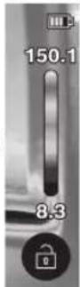
To determine the temperature of a specific area, move the measuring device so that the crosshair with the temperature indicator (m) is aimed at the desired point or area. In automatic mode, the color spectrum of the scale is always distributed evenly across the entire measurement area within the maximum and minimum temperature limits.
The measuring device displays all temperatures measured in the measurement area relative to each other. If heat is displayed as bluish on the color scale in some areas, it means that the bluish region of the measured area has a lower temperature compared to other regions of the measured area. However, these areas may still be within a temperature range that can cause burns. Therefore, always monitor the temperature displayed on the scale or crosshair.
Functions
Follow the navigation information in the various menus (see "Navigating in the various menus", Page 310)

Illuminating the measurement object
The measuring instrument is equipped with a work light (4). It is intended for illuminating the immediate work area of the instrument for taking images and is not designed for continuous work lighting.
To switch the work light on or off, open the left side bar. Navigate to the menu item / and confirm your selection. When the work light is switched on, it is displayed in the status bar.
The light automatically switches off after 2 minutes to avoid affecting measurement accuracy.
You can set the automatic switch-off time in the menu below.
Displaying the thermal image and real image superimposed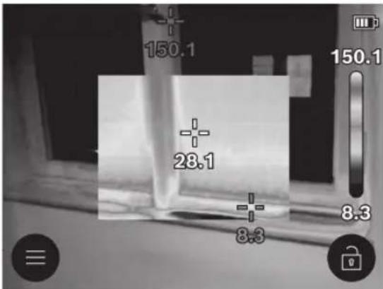
For better orientation (= spatial definition of the displayed thermal image), the visual real image can also be switched on in balanced temperature ranges.
Note: The real image and thermal image are displayed exactly superimposed at a distance of 1 m. If the distance to the measured object differs from this, the real image and thermal image will be displayed
This deviation can be compensated for with special Bosch apps. Information about the apps and their compatibility can be found on the measuring tool's product page or at www.bosch-professional.com/thermal.
The measuring tool offers the following options.
- 100% infrared image
Only the thermal image is displayed.
- Transparency
The displayed thermal image is placed transparently over the real image. This makes it easier to identify objects. To activate/deactivate the setting, open the left sidebar and scroll to the menu item / . Confirm your selection by pressing the center of the multi-function button (17).
- Picture-in-picture
The displayed thermal image is cut out, and the surrounding area is shown as a real image. This setting improves the location of the measuring area.
To activate/deactivate the setting, open the left sidebar and scroll to the menu item / . Confirm your selection by pressing the center of the multi-function button (17).
Adjusting the color display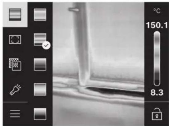
Depending on the measuring situation, different color palettes can simplify the analysis of the thermal image and depict objects or situations more clearly on the screen. This does not affect the measured temperatures. Only the representation of the temperature values changes.
To change the color palette, open the sidebar and scroll to the menu item "Color palette". Confirm your selection by pressing the center of the multi-function button (17).
Fixing the scale
The color distribution is automatically adjusted on the thermal image, but it can also be fixed by pressing the multi-function button (17) to the right and then to the center. This allows you to compare thermal images taken under different temperature conditions (e.g., when checking for thermal bridges between multiple rooms) or to remove a particularly cold or hot object that causes distortion from the thermal image (e.g., a hot object when searching for thermal bridges).
To switch the scale back to automatic adjustment, open the right sidebar and press the multi-function button (17) in the center. The temperatures will now behave dynamically again and adapt to the measured minimum and maximum values.
Main menu
Open the left sidebar (see "Navigating in the different menus", page 310). To go to the main menu, press the multi-function button (17) in the center.
- In this menu item, you can delete saved images individually or all at once.
-
- (a) There are stored emissivity levels for frequently used materials. To make searching easier, the values in the emissivity level catalog are divided into groups. In the menu item, first select the appropriate category and then the appropriate material. If you know the exact emissivity level of the object being measured, you can enter it as a numerical value in the menu item.
• (b)
By setting this parameter, you can improve the measurement result, especially for materials with low emissivity (= high reflectivity). In some cases (especially indoors), the reflected temperature corresponds to the ambient temperature. If objects with very different temperatures can affect the measurement near highly reflective objects, this value must be adjusted. To do this, press the multi-function button (17) to the left or right.
-
To ensure high accuracy over the entire measuring range, measurements are taken in 2 temperature ranges. In the measuring function, the instrument automatically selects the appropriate temperature range based on the temperature distribution in the thermal image. It evaluates how many measured values are above a certain temperature threshold. When measuring very small but very hot objects, a lower temperature range that is not suitable for high temperature measurement may be selected. This can be detected by the symbol \~ placed in front of the temperature display. In such a case, switch to the measuring function <100 °C ... 450 °C> or <-20 °C ... 100 °C>, in which the color distribution corresponds to the set temperature range. The setting is indicated on the scale by an arrow pointing up or down.
-
• (m): / The point is displayed in the center of the thermal image and shows the measured temperature value at that location. • (n): / The hottest point (= measuring pixel) is marked on the thermal image with a red crosshair. This makes it easier to find critical spots (e.g., an open terminal in a switch cabinet). - (I): / The coldest point (= measuring pixel) is marked
on the thermal image with a blue crosshair. This makes it easier to find critical spots (e.g., a leak in a window).
- (i): /
- (c): / The average temperature (c) is displayed on the thermal image at the top left (the average temperature of all measured values in the thermal image). This can help in determining the reflected temperature.
-
In this menu item, you can adjust the brightness of the display lighting. In this menu item, you can select the time interval for automatic shutdown of the work light when no button is pressed.
-
In this menu item, you can select the time interval after which the measuring tool automatically switches off when no button is pressed. You can also deactivate the automatic switch-off by selecting the setting.
-
In this submenu, in addition to changing the time and date, you can also change their format.
-
In this menu item, you can select the language used for the display.
•
In this menu item, you can reset the measuring tool to factory settings and permanently delete all data. Depending on the situation, this may take several minutes. Press the multi-function button (17) to the right to delete all files, or press the multi-function button (17) to the left to cancel the operation.
-
In this menu item, you can view information about the measuring tool. There you will find the serial number of the measuring tool and the version of the installed software. You will also find additional information about the measuring tool and software updates.
You can exit any menu and return to the default view by pressing the measurement button (6).
Measuring tool software update
If necessary, you can update the measuring tool software via the USB Type-C® interface. For more information, visit: www.bosch-professional.com/thermal-update.
Documenting measurement results
Saving measurement results
After switching on, the measuring instrument immediately starts measuring and continues until it is switched off.
To save an image, point the camera at the desired measuring object and press the measuring button (6). The image is saved in the internal memory of the measuring instrument. The measurement is frozen and displayed on the screen. This allows you to carefully observe the image and then adjust it (e.g., color palette). If you do not wish to save the frozen image, press the measuring button (6) again to restart the measuring mode. If
you wish to save the image in the internal memory of the measuring instrument, press the multifunction button (17) in the center.
Viewing saved images
To view saved thermal images, proceed as follows.
- Immediately after saving, press the multifunction button (17) in the center again. The preview of the last saved photo will now appear on the screen.
- Alternatively, you can view saved photos in the menu item .
- To navigate between saved thermal images, press the multifunction button (17) to the right or left. In addition to the thermal image, a visual image was also saved. To open it, press the multifunction button (17) up or down. After 5 seconds, the instrument switches to full image view. In full image view, the title bar display is stopped so that you can view all details of the thermal image.
You can switch views by pressing the multifunction button (17) up and down.
Deleting saved images
To delete individual or all thermal images, press the multifunction button (17) in the center. A submenu opens.
- Here you can choose whether you want to delete only this image or all images. Confirm the selection by pressing the multifunction button (17) in the center. At the selection, you can choose between and . Confirm the selection by pressing the multifunction button (17) in the center.
- In this submenu, you can also view information about the emission level and reflected temperature.
Deleted data fragments remain in memory and can be recreated. To permanently delete them, select in the main menu → .
Data transfer
Data transfer via USB interface
Open the USB Type-C port cover (11). Connect the measuring tool's USB Type-C port (12) to your computer using the supplied USB Type-C cable (16).
Then switch on the measuring tool using the on/off switch (18).
Open the file manager on your computer and select the drive GTC_450. Files stored in the measuring tool's internal memory can be copied, moved to the computer, and deleted.
When you have finished the desired operation, disconnect the drive from the computer in the usual way, then switch off the measuring tool using the on/off switch (18).
Caution! Always log out the drive from your operating system first (i.e., eject the drive), otherwise the measuring tool's internal memory may be damaged. Remove the USB Type-C® cable and close the cover (11). Always keep the USB interface cover closed to prevent dust and water spray from entering the housing.
Note. The measuring tool may only be connected to a computer via USB. Connecting to other devices may damage the measuring tool.
Note. The USB Type-C® interface is intended solely for data transfer. It cannot be used to charge batteries.
Post-processing of thermal images
You can post-process saved thermal images with special Bosch apps. Information about the apps and their compatibility can be found on the measuring tool's product page or at www.bosch-professional.com/thermal.
Errors – causes and remedies
In the event of a malfunction, the measuring tool performs a restart and can then be used again. For other cases, you can find help in the overview of error messages below.
Error Cause Remedy
| Mõöteriista ei saa sisse lülitada. | Aku/patareid on tühjad Laadige aku või vahetage patareid. | |
 | Aku/patareide viga Vahetage aku või patareid. | |
 | Aku/patareid on liiga soojad või liiga külmadLaske akul jõuda ettenähtud temperatuurile või vahetage aku või patareid. | |
 | Mõöteriist on liiga soe või liiga külmLaske mõöteriista temperatuuril kohaneda. | |
314|Estonian
Error Cause Remedy
The measuring tool cannot be connected to the computer.
USB connection or USB cable defective
Check whether the measuring tool can be connected to another computer. If not, send the measuring tool to the Bosch authorized customer service.
Note: Always use the USB cable from the delivery package.
Button cell battery empty Replace the button cell battery (see "Replacing the button cell battery (see Fig. C)", page 314). Confirm the replacement with "OK" by pressing the center of the multi-function button (17).
Explanation of terms
For more detailed information, see www.bosch-professional.com/thermal etc.
Infrared thermal radiation
Infrared thermal radiation is electromagnetic radiation emitted by any body with a temperature above 0 kelvin (-273 °C). The amount of radiation depends on the body's temperature and emissivity.
Emissivity
The emissivity of an object depends on the material and surface structure. It indicates how much infrared thermal radiation the object emits compared to an ideal thermal radiator (blackbody, emissivity € = 1) and can be between 0 and 1.
Thermal bridge
A thermal bridge is a location in the building envelope where heat loss is greater due to the construction. Thermal bridges can lead to an increased risk of mold.
Reflected temperature / reflectivity of the object
Reflected temperature is the thermal radiation that the object itself does not emit. Depending on the structure and material, radiation from the surroundings is reflected by the object being measured, distorting its temperature measurement result.
Distance to the object
The distance between the measuring object and the measuring device affects the size of the measured surface per pixel. As the distance to the object increases, you can measure larger objects.
| Kaugus (m) Infrapunapiksli suurus (mm) | Infrapunapiirkonna laius × kõrgus (m) |
| 0,30 1,14 ~ 0,29 × 0,22 | |
| 0,55 2,08 ~ 0,53 × 0,40 | |
| 1,00 3,79 ~ 0,97 × 0,73 | |
| 2,00 7,58 ~ 1,94 × 1,46 | |
| 5,00 18,95 ~ 4,85 × 3,64 |
Maintenance and care
Maintenance and cleaning
Store and transport the measuring tool only in a suitable case, such as the original packaging.
Always keep the measuring tool clean. If the infrared sensor (5) is dirty, it can reduce measurement accuracy.
When cleaning, no liquid must enter the interior of the measuring tool.
Do not attempt to remove dirt from the infrared sensor (5), camera (3), work light (4), or laser exit aperture (2) with sharp objects. Do not wipe the infrared sensor or camera (risk of scratching).
Regularly clean the surfaces, especially at the laser exit aperture, and ensure that no lint from the cleaning cloth remains there.
If you wish to have your measuring tool recalibrated, contact an authorized Bosch customer service center. Send the measuring tool for repair in its original packaging.
There are no parts in the measuring tool that require user maintenance. Opening the housing cover can damage the measuring tool to an extent that renders it unusable.
Replacing the button cell battery (see figure C)
Open the cover (11).
Unscrew the screw (10) of the battery holder. Pull the battery holder (9) out of the measuring tool. Replace the battery. After installing the battery holder, tighten the screw (10) again.
Customer service and application advice
Sales representatives will answer questions regarding repair and maintenance of the product as well as spare parts. You can find information about detailed drawings and spare parts at:
www.bosch-pt.com
You can get answers to questions about products and accessories from Bosch application advisors.
Please always state the 10-digit product code, which can be found on the product's rating plate, for inquiries and spare parts orders.
Republic of Estonia
Service center
Tel.: (+372) 6549 575
Fax: (+372) 6549 576
E-mail: service-pt@lv.bosch.com
You can find other service addresses at:
www.bosch-pt.com/serviceaddresses
Transport
The recommended lithium-ion batteries are subject to the regulations for the transport of dangerous goods. The user may transport the batteries by road without restrictions.
If the consignor is a third party (e.g., air freight or forwarding), special requirements for packaging and labeling must be observed. A dangerous goods expert must be involved in preparing the product for transport.
Batteries may only be shipped if the battery housing is undamaged. Cover exposed contacts and pack the battery so that it does not move in the packaging. Also follow any additional national regulations.
Waste disposal

Measuring devices, batteries, accessories, and packaging should be directed to environmentally friendly recycling.
Do not dispose of measuring devices or batteries in household waste!
Only for EU member states:
Disused measuring instruments and defective or used batteries must be directed to separate waste disposal. Use the designated collection systems. Improper disposal of old electrical and electronic equipment may harm the environment and human health due to potentially hazardous substances.
Batteries:
Li-Ion:
Follow the instructions in the Transport section (see "Transport", page 315).
Safety instructions

To work safely with the measuring instrument, carefully read and follow all instructions provided here. If the measuring instrument is not used in accordance with the instructions
provided here, its protective functions may be adversely affected. Ensure that the warning labels on the measuring instrument are always clearly legible. KEEP THESE INSTRUCTIONS AFTER READING; IF YOU PASS THE MEASURING INSTRUMENT ON, PROVIDE THEM WITH THE INSTRUMENT.
Caution – if operations or adjustments are performed other than those specified here or in other procedure descriptions, this may result in hazardous radiation exposure.
▶ The measuring tool is supplied with a laser warning sign (it is marked in the illustration of the measuring tool shown on the graphic page). If the text on the warning label is not in your country's language, before using the product for the first time, stick the label supplied with the product in your country's language over it.
Do not direct the laser beam at other persons or animals, and do not look into the direct or reflected laser beam. Doing so can blind persons in the vicinity, cause accidents, or even damage eyesight.
▶ If the laser beam hits your eyes, immediately close your eyes and move your head out of the beam. ▶ Do not make any modifications to the laser device. ▶ Do not use the laser viewing glasses (accessory) as protective goggles. Laser viewing glasses are intended to improve visibility of the laser beam, but they cannot protect your eyes from laser radiation. ▶ Do not use the laser viewing glasses (accessory) as sunglasses or as glasses while driving a vehicle. Laser viewing glasses do not provide full protection from ultraviolet radiation and impair color discrimination. Ensure that the measuring tool is repaired only by qualified repair specialists using original spare parts. This will maintain the required level of operational safety when working with the measuring tool. ▶ Do not allow children to use the laser measuring tool without adult supervision. They may accidentally blind persons in the vicinity or themselves. Do not work with the measuring tool in explosive atmospheres where flammable liquids, gases, or dusts are present. Sparks may be generated in the measuring tool, which can ignite dust or vapors. ▶ Do not open the battery or make any modifications to it. There is a risk of short-circuiting. As a result of damage or improper use, the battery may emit harmful fumes. The battery may catch fire or explode. Ventilate the room with fresh air and in severe cases seek medical attention. Fumes may cause irritation of the respiratory tract. If the battery is damaged or improperly used, liquid electrolyte may leak. Avoid contact of the electrolyte with skin. If it does happen accidentally, rinse the electrolyte with water. If electrolyte gets into eyes, immediately seek medical attention. Leaked electrolyte from the battery can cause skin inflammation or even burns. ▶ Impact on the battery with a sharp object, such as a nail or screwdriver, as well as the effect of external force, can damage the battery. This can cause an internal short circuit, which may result in the battery catching fire, smoking, exploding, or overheating.
▶ When the battery is not in use, do not allow its contacts to come into contact with paper clips, coins, keys, nails, screws, or other small metal objects that could cause a short circuit. A short circuit between the battery contacts can cause burns and be a cause of fire. ▶ Use the battery only in products manufactured by the manufacturer. Only in this way is the battery protected from dangerous overloads. Charge batteries only with chargers recommended by the manufacturer for this purpose. Each charger is designed for a specific type of battery, and attempting to use it to charge a different type of battery can lead to fire.


Protect the battery from heat, such as prolonged exposure to direct sunlight, as well as from fire, dirt, water, and moisture. This can create a risk of explosion and short circuit.


WARNING


Ensure that button cells do not get into the hands of children. Button cells are dangerous.
Button cells must never be swallowed or enter other body openings. If you suspect that a button cell has been swallowed or has entered another body opening, seek medical help immediately. A swallowed button cell can cause serious internal organ damage and death within 2 hours. ▶ When replacing the button cell, make sure it is replaced correctly. There is a risk of explosion. ▶ Use only the button cell batteries specified in these operating instructions. Do not use other button cell batteries or other power sources. ▶ Do not attempt to recharge the button cell and do not allow a short circuit to form between its terminals. The button cell can lose its seal, explode, catch fire, and injure people. ▶ Remove and dispose of used button cells in accordance with applicable regulations. Used button cells can lose their seal and, for this reason, damage the product or injure people. ▶ Do not overheat the button cell and do not throw it into fire. The button cell can lose its seal, explode, catch fire, and injure people. ▶ Do not damage or disassemble the button cell. The button cell can lose its seal, explode, catch fire, and injure people. ▶ Do not allow a damaged button cell to come into contact with water. If leaked lithium comes into contact with water, hydrogen can form, which can cause fire, explosion, or injure people.
Stop using the measuring tool if the button cell battery retainer can no longer be closed completely and correctly; remove the button cell batteries and have the measuring tool repaired. ▶ If there are large temperature differences in the thermal image, high temperature values may be displayed in a color associated with low temperature. Touching such a surface can cause burns. ▶ Correct temperature measurements are only possible if the set emissivity coefficient matches the object's actual emissivity coefficient. Objects may be displayed with too high or too low temperature, which can pose a contact risk. ▶ Do not point the measuring tool directly at the sun or high-power CO₂ lasers. This can damage the detector. Protect the measuring tool from moisture, snow, dust, and dirt, especially in the area of the infrared lens, speaker, and microphone. The receiver lens may fog up or become dirty, leading to incorrect measurement results. Due to incorrect instrument settings and other atmospheric factors, measurement results may be erroneous. Objects may be displayed with too high or too low temperature, which can pose a hazard during contact.
Product description and functions
Please observe the figures at the end of the operating instructions.
Intended use
This thermal imaging camera is intended for non-contact measurement of surface temperatures.
The displayed thermal image shows the temperature distribution in the field of view of the thermal imaging camera, with temperature differences represented by different colors.
When used correctly, the device can be used to check temperature differences or anomalies on surfaces and objects without touching them, making components and/or possible defects visible, including:
- checking thermal insulation and insulation (e.g., detecting thermal bridges),
- active heating and hot water pipes (e.g., underfloor heating) in floors and walls,
- overheated electrical components (e.g., fuses or terminals),
- damaged machine parts (e.g., overheating due to defective ball bearings).
The measuring tool is not intended for measuring gas temperatures. The measuring tool must not be used for human medical treatment.
For information on use in veterinary medicine, see www.bosch-professional.com/thermal.
The measuring tool is suitable for use both indoors and outdoors.
This product is a consumer laser product according to standard EN 50689.
This measuring tool's illumination element is designed to illuminate the direct working area of the measuring tool for image capture.
The laser points must not be used as a laser pointer. They are only used to mark the measuring area.
Illustrated components
The numbering of the illustrated components corresponds to the numbers in the illustration of the measuring tool on the graphic page.
(1) Protective cover (2) Laser beam outlet (3) Optical camera (4) Work lamp (5) Infrared sensor (6) Measurement pause/start button (7) Battery compartment (8) Laser warning label (9) Coin cell battery holder (10) Coin cell battery holder screw (11) USB socket and coin cell battery holder cover (12) USB Type-C® socket a) (13) Laser button (14) Battery/battery adapter release button (15) Battery b) (16) USB Type-C® cable b) (17) Multi-function button (18) On/off/back button
(19) Display (20) Serial number (21) Battery adapter housing (22) Batteries b) (23) Battery adapter cap a) USB Type-C® and USB-C® are trademarks of USB Implementers Forum. b) The accessories shown or described are not included in the standard delivery scope.
Indication elements
(a) Emissivity reading (b) Reflected temperature reading (c) Average temperature reading (d) Full memory medium symbol (e) Work lamp symbol (f) Laser symbol (g) Charge level indicator (h) Maximum surface temperature reading of the measuring area (i) Scale (j) Minimum surface temperature reading of the measuring area (k) Temperature scale locking symbol (l) Cold spot reading (example) (m) Target crosshair with temperature reading (n) Hot spot reading (example) (o) Menu symbol
Technical data
| Termogrāfijas kamera GTC 12V-450-13 | |
| Izstrādājuma numurs | 3 601 K83 900 |
| Infrasarkanā starojuma sensora izšķirtspēja 256 × 192 px | |
| Termiskā jutībaA) | ≤ 50 mK |
| Spektrālais diapazons 8–14 μm | |
| Skata lauks (FOV)A) | 55,6° × 42° |
| Izšķirtspēja telpā (IFOV) 3,79 mrad | |
| Fokusa attālumsA) | ≥ 0,5 m |
| Fokuss Fiksēts | |
| Siltumattēla atjaunošanas frekvence ≤ 9 Hz | |
| Virsmas temperatūras mērišanas diapazonsA) | -20 ... +450 °C |
| Virsmas temperatūras mērišanas precizitāteA(B)C) | |
| >0 °C ... ≤ +100 °C) | ±2 °C |
| >+100 °C) | ±2% |
| Temperatūras izšķirtspēja 0,1 °C | |
| Displeja tips TFT | |
| Displeja lielums 2,8" | |
| Displeja izšķirtspēja 480 × 360 px | |
Thermal imaging camera GTC 12V-450-13
| Iebūvētās optiskās kameras izšķirtspēja 2 MP (640 × 480 px) | |
| Attēla formāts .jpg | |
| Vienā saglabāšanas reizē saglabātie elementi 1 × siltumattēls (ekrānuzņēmums) | |
| 1 × vizuālais reālais attēls ar temperatūras vērtībām (metadati) | |
| Maks.attēlu skaits iekšējā attēlu atmiņā 500 | |
| Maks. darba augstums virs jūras līmeņa 2000 m | |
| Piesārņojuma pakāpe atbilstīgi standartam IEC 61010-1 2 | F) |
| Maks. relatīvais gaisa mitrumsA) | 90% |
| Lāzera klase 2 | |
| Lāzera veids < 1 mW, 645–660 nm | |
| Lāzera stara divergence 1,5 mrad (pilns leņķis) | |
| Elektrobarošana | |
| - Akumulators (litija-jonu) 12 V | |
| - Baterijas (sārma-mangāna, ar bateriju adapteri) 4 × 1,5 V LR6 (AA) | |
| - Akumulatori (NiMH, ar bateriju adapteri) 4 × 1,2 V HR6 (AA) | |
| Darbības ilgumsG) | |
| - Akumulators (litija-jonu)H)I) | 8 st. |
| - Baterijas (sārma-mangāna) 4 st. | |
| Sistēmas laika elektrobarošana CR1225 (3 V litija baterija) | |
| USB standarts 2.0 | |
| USB saskarne | USB Type-C® |
| SvarsJ) | 0,354 kg |
| Izmērs (garums × platums × augstums)K) | 89 × 79 × 209 mm |
| Aizsardzības klase (izņemot akumulatoru/baterijas, vertikālā pozīcijā) | IP54 |
| Ieteicamā apkārtējās vides temperatūra uzlādes laikā | 0 °C ... +35 °C |
| Pieļaujamā apkārtējās vides temperatūra | |
| - Lietošanas laikā | -10 °C ... +50 °C |
| - Glabājot ar akumulatoru | -20 °C ... +50 °C |
| - Glabājot bez akumulatora | -20 °C ... +70 °C |
| Ieteicamie akumulatori | GBA 12V... |
| Ieteicamās uzlādes ierices | GAL 12... GAX 18... |
A) According to VDI 5585 standard (average value)
B) At ambient temperature 20–23 °C and emissivity > 0.95, measuring distance: 1 m, operating time: > 5 min, aperture: 150 mm, with work lamp and laser switched off
C) Including difference depending on usage (e.g., reflection, distance, ambient temperature)
D) Applies to the center point; for all other pixels, an additional ±1 °C.
E) Applies to the center point; for all other pixels, an additional ±1%.
F) Usually only non-conductive contamination is observed, but occasionally temporary electrical conductivity due to condensation may occur.
G) With the work lamp switched off and medium display brightness.
H) Depending on the battery used.
1) At an ambient air temperature of 20-30 °C.
J) Weight without battery/battery adapter/batteries.
K) With GBA 12V 2.0Ah or battery adapter.
To clearly identify the measuring tool, the serial number (20) is indicated on its rating plate.
Power supply for the measuring tool
The measuring tool can be operated with a Bosch Li-ion battery, commercially available batteries, or NiMH batteries.
Operation with battery (see figure A)
Use only the charging devices specified in the technical parameters. Only these charging devices are suitable for charging the lithium-ion battery used in your measuring tool.
Note: According to international transport regulations, lithium-ion batteries are delivered in a partially charged state. To ensure full battery capacity, fully charge the battery before first use.
To insert a charged battery (15), push it into the battery compartment (7) until the battery locks into place with a clearly audible click.
To remove the battery (15), press the release button (14) and pull the battery out of the battery compartment (7). Do this without applying force.
Battery operation (see figure B)
For operating the measuring tool, it is recommended to use alkaline manganese batteries or NiMH rechargeable batteries.
The batteries are inserted into the battery adapter.
The battery adapter is intended for use only in Bosch measuring tools designed for this purpose and must not be used with power tools.
To insert the batteries, slide the battery adapter sleeve (21) into the battery compartment (7). Insert the batteries into the sleeve as shown in the figure on the end cap (23). Slide the end cap onto the sleeve until it audibly clicks into place.
To remove the batteries (22), press the release buttons (14) that hold the end cap (23), then pull off the end cap. Remove the batteries. To remove the sleeve (21) inserted in the battery compartment, grasp the sleeve and pull it out of the measuring tool, gently pressing on the side wall.
Always replace all batteries or rechargeable batteries at the same time. Use only batteries or rechargeable batteries of the same capacity and from the same manufacturer.
If the measuring tool is not used for a longer period, remove the batteries or rechargeable batteries from it. Storing batteries and rechargeable batteries in the measuring tool for a long time can cause them to corrode.
Proper handling of the rechargeable battery
Protect the rechargeable battery from moisture and water.
Store the rechargeable battery at temperatures between -20 °C and 50 °C. Do not leave the rechargeable battery in heat, for example, do not leave it in a car during summer.
If the tool's operating time between battery charges noticeably decreases, this indicates that the battery is worn out and needs to be replaced.
Observe the instructions for disposal of worn-out products.
Operation
▶ Protect the measuring tool from moisture and direct sunlight. ▶ Do not expose the measuring tool to very high or very low temperatures or to sudden temperature changes. For example, do not leave the measuring tool in a car for an extended period. In the event of large temperature fluctuations, wait until the temperature of the measuring tool has equalized with the ambient temperature before using it. Exposure to extreme temperatures or sudden temperature changes can adversely affect the accuracy of the measuring tool. ▶ Ensure that the measuring tool is properly acclimatized. If there are pronounced temperature fluctuations, acclimatization can take up to 60 minutes. This can happen, for example, if the measuring tool is stored in a cold car and then a measurement is taken in a warm building. ▶ Do not subject the measuring tool to strong impacts or allow it to fall. If the measuring tool has been subjected to strong external influences or if it shows signs of malfunction, it must be sent to a Bosch authorized customer service center for inspection.
Starting Operation
First Use
On the first time the measuring tool is switched on, or after resetting to factory settings, some basic settings must be made. Select the desired values by pressing the multi-function button (17) at the bottom, top, left, or right. Press the center of the multi-function button (17) to confirm the selected parameters. The next setting is displayed as soon as the selected parameters have been confirmed. The total number of settings and the remaining settings are shown in the upper status bar.
The following basic settings are available:
Switching On/Off
To measure, open the protective cap (1). During operation, ensure that the infrared sensor is not closed or covered.
To switch on the measuring tool, press the on/off button (18). The start-up procedure is shown on the display (19). Immediately after the start-up procedure, the measuring tool begins measuring and continues to measure until it is switched off.
Note: In the first few minutes, the measuring tool may perform self-calibration more frequently, as the sensor and ambient temperatures have not yet equalized. Repeated sensor calibration improves measurement accuracy.
During calibration, the temperature reading may be marked with \~. In the event of large ambient temperature fluctuations,
this effect intensifies. Therefore, if possible, switch on the measuring tool several minutes before starting measurement so that it can thermally stabilize.
To switch off the measuring tool, press the on/off button (18) for > 1 s. All settings are saved in the measuring tool, and the measuring tool is switched off.
Close the protective cap (1) to transport the measuring tool safely.
In the main menu, you can set whether and after what period of time the measuring tool is automatically switched off (see "Main Menu", Page 322).
If the battery or measuring instrument temperature is outside the operating temperature range specified in the technical data, the measuring instrument is automatically switched off after a brief warning (see "Faults – Causes and remedies", page 324).
Allow the measuring instrument temperature to equalize and then switch it on again.
Navigating in the various menus
Navigating in the various menus of the measuring instrument:
- Opening the menu bar: press the multifunction button (17) in the middle or on the left side. The menu bars are displayed on the right and left sides of the display; the main menu is highlighted.
- Scrolling in the left menu bar/navigating in the main menu: press the multifunction button (17) at the top, bottom, left, or right.
- Switching to the left or right menu bar: press the multifunction button (17) on the left or right side respectively. – Confirming a selection/switching to a submenu: press the multifunction button (17) in the middle. – Switching from a submenu to a higher menu level: press the "Back" button (18).
Preparing for measurement
Setting the emissivity for surface temperature measurements
The emissivity of an object depends on the material and surface structure of the object. It indicates how much infrared radiation the object emits compared to an ideal heat radiator (black body, emissivity ε = 1), and accordingly has a value between 0 and 1.
To determine the surface temperature without contact, the natural infrared heat radiation emitted by the target object is measured. To obtain accurate measurement results,
the emissivity set in the measuring instrument must be checked before each measurement and, if necessary, adjusted to the object being measured.
The emissivity values preset in the measuring instrument are reference values.
You can select one of the preset emissivity values or enter an exact numerical value. Set the desired emissivity in the menu → (see "Main menu", page 322).
▶ Correct temperature measurements are only possible if the set emissivity value matches the actual emissivity value of the object.
The lower the emissivity, the more the reflected temperature affects the measurement result. Therefore, always adjust the reflected temperature when the emissivity changes. Set the reflected temperature in the menu → (see "Main Menu", page 322).
Apparent temperature differences displayed by the measuring instrument can arise due to different temperature values and/or different emissivities. If the emissivities differ greatly, the displayed temperature differences can differ significantly from the actual temperature differences.
If there are multiple measuring objects in the measuring area made of different materials or with different structures, the displayed temperature values are accurate only for those objects whose emissivity matches the set emissivity. Color differences of other objects (with different emissivities) can only indicate the relationships between temperature values.
Instructions on measuring conditions
Highly reflective or mirror-smooth surfaces (e.g., glossy tiles or shiny metal) can provide incorrect measurement values or significantly affect measurement results. If necessary, cover the measuring surface with a dark, matte adhesive tape that conducts heat well. Wait a short time until the tape temperature equalizes with the surface temperature of the measuring object.
For reflective surfaces, maintain a suitable measuring angle so that thermal radiation reflected from other objects does not distort the results. For example, when measuring vertically from the front, the heat reflection from your body can negatively affect the measurement. Measuring a flat surface may show the contour and temperature of your body (reflection value), which does not correspond to the actual temperature of the measuring surface (emission value) or the real surface value. Surface temperature measurements of transparent materials (e.g., glass or transparent plastic) are fundamentally impossible.
The more suitable and stable the measuring conditions, the more accurate and reliable the measurement results. Not only pronounced ambient temperature fluctuations but also pronounced temperature fluctuations of the measuring object are important factors that can negatively affect accuracy.
Infrared radiation measurement results are negatively affected by smoke, steam/high humidity, or dusty air.
Instructions for performing more accurate measurements.
– Stand as close as possible to the measuring object to reduce interference between you and the measuring surface. - Ventilate indoor areas before measuring, especially if there is dust or a lot of steam in the air. After ventilating the room, wait a while until the normal temperature is restored.
Marking the measuring spot
▶ Do not point the laser beam at other persons or animals and do not look into the laser beam even from a great distance.
The measuring instrument is equipped with a laser to mark the measuring spot.
Press and hold the laser button (13). The laser symbol (f) appears in the status bar, and a red circle (m) appears around the crosshair. The laser and crosshair overlap precisely at a distance of 1 m. When you release the laser button (13), the laser switches off.
Temperature determination using the scale
A scale (i) is shown on the right-hand side of the display. The values at the top and bottom of the scale correspond to the maximum temperature (h) and minimum temperature (j) determined in the thermal image. When creating the scale, 99.99% of all pixels are evaluated. The color is assigned to the temperature value in the image in a uniform (linear) distribution.
This allows temperature values within the range between the two end values to be assigned to different color shades. For example, a temperature exactly halfway between the maximum and minimum values corresponds to the middle color range of the scale.
To determine the temperature of a specific area, move the measuring tool so that the crosshair with the temperature reading (m) is aimed at the desired point or area. If the automatic setting is enabled, the color spectrum of the scale is linearly (= evenly) distributed across the entire measuring range from the maximum to the minimum temperature. The measuring tool displays all measured temperature values in the measuring area relative to each other. If, for example, in a colored display, heat is shown in bluish colors in the color palette, this means that the bluish areas correspond to the coldest measured values in the current measuring area. However, these areas may be within a temperature range that can cause injuries under certain conditions. Therefore, always pay attention to the displayed temperature values on the scale or directly at the crosshair.
Functions
Note the information on navigating through the various menus (see "Navigating through the various menus", page 320)

Illumination of the measuring object
The measuring tool is equipped with a work lamp (4). It is intended to illuminate the immediate work area of the measuring tool for image capture and is not intended for use as a permanent work light.
To switch the work light on/off, open the left menu bar. Scroll to the menu item / and confirm your selection. If the work lamp is switched on, this is shown in the status bar.
The light is automatically switched off after 2 minutes to avoid affecting the measuring accuracy.
The automatic switch-off time can be set in the menu under .
Overlaying the thermal image and the real image
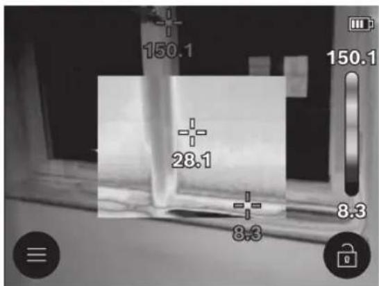
To make it easier to orientate yourself (= to link the displayed thermal image with the layout in the room), a visual real image can be added in the case of an equalized temperature range.
Note: The real image exactly overlays the thermal image at a distance of 1 m to the measuring object. If the distance to the measuring object differs, the real image is offset relative to the thermal image due to the operating principle. This offset can be corrected using special Bosch apps. Information on the apps and their compatibility can be found on the product page for the measuring tools or at www.bosch-professional.com/thermal.
The measuring instrument offers the following options:
- 100% infrared image Only the thermal image is displayed.

Transparency
The displayed thermal image is transparent and placed over the real image. This allows for better identification of objects. To activate/deactivate the settings, open the left menu bar and scroll to the menu item / . Confirm your selected parameters by pressing the center of the multi-function key (17).

In the image
In the displayed thermal image, the edges are cut off and the surrounding area is shown as the real image. Using this setting, you can better identify the measuring area in the room. To activate/deactivate the settings, open the left menu bar and scroll to the menu item / . Confirm your selected parameters by pressing the center of the multi-function key (17).
Adjusting the color display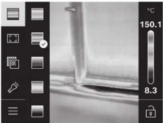
The option to choose different color palettes depending on the measuring situation can facilitate the analysis of the thermal image and display objects and situations more clearly on the screen. This does not affect the measured temperature values in any way. Only the representation of the temperature values changes.
To change the color palette, open the side menu bar and scroll to the menu item "Color palette". Confirm your selected parameters by pressing the center of the multi-function key (17).

Fixing the scale
The color distribution for the thermal image is adjusted automatically, but it can be set by pressing the right side of the multi-function key (17) and then the center. This can be used to compare thermal images taken under different temperature conditions (e.g., when checking thermal bridges in several rooms) or to hide very cold or very hot objects in the thermal image that would otherwise distort the image (e.g., hiding a radiator as a hot object when looking for thermal bridges).
To switch the scale back to automatic mode, open the right menu bar and press the center of the multi-function key (17). The distribution of temperature values is dynamic again and is adjusted to the measured minimum and maximum values.
Main menu
Open the left menu bar again (see "Navigating in the various menus", Page 320). To get to the main menu, press the center of the multi-function key (17).
- In this menu item, you can delete individual images or delete all images at once.
-
• (a)
For some commonly used materials, emissivity coefficients are already stored and can be selected. To simplify the search, the values are grouped in the emissivity values catalog. In the menu item, first select the appropriate category and then the material. If you know
the exact emissivity coefficient of the object being measured, you can also enter it as a numerical value in the menu item.
• (b)
Setting this parameter can improve measurement results, especially for materials with low emissivity (= higher reflectivity). In some situations (especially indoors), the reflected temperature value corresponds to the ambient temperature value. If the measurement result can be influenced by objects with very different temperature values that are in the vicinity of highly reflective objects, this value must be adjusted. Press the multifunction key (17) on the left or right side.
-
To ensure a high level of accuracy over the entire measuring range, measurement takes place in 2 temperature ranges. In the measuring function, the measuring instrument automatically selects the appropriate temperature range based on the temperature distribution in the thermal image. This is done by evaluating how many of the measured values exceed a certain temperature threshold. If small but hot objects need to be measured, a low temperature range that is not suitable for high temperatures may be selected. This can be recognized by a preset symbol \~ in the temperature reading. In that case, make changes in the measuring function <100 °C ... 450 °C> or <-20 °C ... 100 °C>, where the color distribution corresponds to the set temperature range. The setting is marked on the scale with an upward or downward pointing arrow.
-
- (m): / The point is displayed in the middle of the thermal image; it represents the measured temperature value at that location.
- (n): /
The hottest point (= measuring pixel) is marked with a red crosshair in the thermal image. This makes it easier to find critical areas (e.g., a loose contact in a control cabinet).
- (I): /
The coldest point (= measuring pixel) is marked with a blue crosshair in the thermal image. This makes it easier to find critical areas (e.g., a leak in a window).
• (i): /
The average temperature (°C) is displayed in the upper left corner of the thermal image (the average temperature of all values measured in the thermal image). This can help determine the reflected temperature.
In this menu item, you can adjust the brightness level of the display.
In this menu item, you can select the time interval after which the work light is automatically switched off if no button is pressed during this time.
In this menu item, you can select the time interval after which the measuring instrument is automatically switched off if no button is pressed during this time. You can also deactivate the automatic switch-off by selecting the setting .
In this submenu, you can not only set the time and date, but also change their format.
In this menu item, you can select the language used on the display.
In this menu item, you can restore the measuring instrument's factory settings and irreversibly delete all data. In some cases, this may take several minutes. To delete all files, press the multifunction button (17) on the right side or the left function button (17) to cancel the operation.
-
In this menu item you can view information about the measuring tool. Here you will find the serial number of the measuring tool and the installed software version. Additionally, you will find more detailed information about the measuring tool, as well as about software updates.
To close any menu and return to the default indication screen, you can also press the measuring button (6).
Updating the measuring tool software
If necessary, the measuring tool software can be updated via the USB Type-C® interface. For information, see the website:
www.bosch-professional.com/thermal-update.
Documenting measurement results
Saving measurement results
Immediately after switching on, the measuring tool starts measuring and continues to measure until it is switched off.
To save an image, point the camera at the desired object to be measured and press the measuring button (6). The image is saved in the internal memory of the measuring tool. The measurement is captured and displayed on the screen. You can now examine the image closely and then adjust it (for example, by selecting a color palette). If you do not want to save the captured image, press the measuring button (6) to continue in measuring mode. If you want to save the image in the internal memory of the measuring tool, press the center of the multi-function button (17).
Viewing saved images
To view the saved thermal images, proceed as described below.
– Immediately after saving, press the center of the multi-function button (17) again. A preview of the last saved photo is displayed on the screen. - Another way to open the saved photos is to open them in the menu item . - To scroll through the saved thermal images, press the left or right side of the multi-function button (17).
Along with the thermal image, a visual image is also saved. To open it, press the top or bottom of the multi-function button (17).
After 5 seconds, the measuring tool switches to full-screen mode. In full-screen mode, the title bar is hidden so that all details of the thermal image are visible.
The display can be changed by pressing the multi-function key (17) up and down.
Deleting saved images
To delete individual or all thermal images, press the multi-function key (17) in the middle. A submenu opens.
- Here you can choose whether you want to delete only this image or all images. Confirm your selected settings by pressing the multi-function key (17) in the middle. When making a selection, you can choose either one or the other. Confirm your selected settings by pressing the multi-function key (17) in the middle.
- In this submenu, you can also view information about the emission coefficient and the reflected temperature.
Image data fragments are stored in memory and can be restored. To permanently delete data, select → in the main menu.
Data transfer
Data transfer via USB interface
Open the cover of the USB Type-C® connection (11). Connect the USB Type-C® connection (12) of the measuring device to your computer using the included USB Type-C® cable (16).
Then switch on the measuring instrument with the on/off key (18).
Open the file explorer on the computer and select the drive GTC_450. The saved files from the internal memory of the measuring instrument can be copied, moved to the computer, or deleted.
Once the selected process is complete, disconnect the drive from the computer as usual and switch off the measuring instrument with the on/off key (18).
Caution: always disconnect the drive from your operating system first (eject action), otherwise the internal memory of the measuring instrument may be damaged.
Disconnect the USB Type-C® cable and close the cover (11).
Always keep the USB connection cover closed to prevent dust or water splashes from entering the housing.
Note: When using USB, connect the measuring tool only to a computer. Connecting it to other devices may damage the measuring tool.
Note: The USB Type-C® interface is used only for data transfer. It cannot be used to charge batteries or rechargeable batteries.
Thermal image post-processing
You can process saved thermal images with special Bosch apps. Information about the apps and their compatibility can be found on the measuring tool product page or at www.bosch-professional.com/thermal.
Faults – causes and remedies
In the event of a fault, the measuring tool restarts automatically and can then be used again. If fault messages are displayed repeatedly, use the overview below.
Fault Cause Remedy
| Mērinstrumentu nevar ieslēgt. Akumulators/baterijas ir izlādējušās | Uzlādējiet akumulatoru vai nomainiet baterijas. | |
 | Akumulatora/bateriju klūda Nomainiet akumulatoru vai baterijas. | |
 | Akumulators/baterijas ir pārāk sakarsušas vai pārāk atdzisušas | Laujiet akumulatoram sasniegt apkārtējās vides temperatūru vai nomainiet akumulatoru vai baterijas. |
 | Mērinstruments ir pārāk sakarsis vai pārāk atdzisis | Pagaidiet, līdz mērinstrumenta temperatūra ir izlīdzinājusies. |
 | Bojāta USB ligzda vai USB kabelis | Pārbaudiet, vai mērinstrumentu var savienot ar citu datoru. Ja savienošana nav iespējama, nosūtiet mērinstrumentu autorizētam Bosch klientu dienestam. |
| Mērinstrumentu nevar savienot ar datoru. | Norāde: vienmēr izmantojiet piegādes komplektācijā iekļauto USB kabeli. | |
 | Izlādējusies pogas tipa baterija | Nomainiet pogas tipa bateriju (skatīt „Pogas tipa baterijas nomaiņa (skatiet attēlu C)“, Lappuse 325). Apstipriniet savus izvēlētos parametrus ar „OK” komandu, nospiežot daudzfunkciju taustiņu (17) vidū. |
Explanation of terms
For more information, see www.bosch-professional.com/thermal.
Infrared radiation
Infrared thermal radiation is electromagnetic radiation emitted by any body whose temperature is greater than 0 on the Kelvin scale (−273 °C). The amount of radiation depends on the body's temperature and its emissivity.
Emissivity
An object's emissivity depends on the object's material and its surface structure. It indicates how much infrared radiation the object emits compared to an ideal thermal radiation source (black body, emissivity ε = 1), and accordingly has a value from 0 to 1.
Thermal bridges
A thermal bridge is a flaw or deficiency in a building's exterior wall construction where a localized increased heat loss occurs.
Thermal bridges can create an increased risk of mold formation.
Reflected temperature/object reflectivity
Reflected temperature is the thermal radiation that is not emitted by the object itself. Depending on the structure and material of the surrounding environment,
radiation is reflected onto the measured object and thus distorts the true temperature measurement result.
Distance to the object
The distance from the measured object to the measuring instrument affects how much surface area each pixel captures. The greater the distance to the object, the larger the objects that can be captured.
| Attālums (m) Infrasarkanā attēla pikseļa lielums (mm) | Platums × infrasarkanā apgabala augstums (m) |
| 0,30 1,14 ~ 0,29 × 0,22 | |
| 0,55 2,08 ~ 0,53 × 0,40 | |
| 1,00 3,79 ~ 0,97 × 0,73 | |
| 2,00 7,58 ~ 1,94 × 1,46 | |
| 5,00 18,95 ~ 4,85 × 3,64 |
Service and maintenance
Service and cleaning
Store and transport the measuring instrument only in suitable packaging, such as the original packaging.
Keep the measuring instrument clean. A dirty infrared sensor (5) can affect measurement accuracy.
During cleaning, do not allow liquid to enter the measuring instrument.
Do not attempt to remove dirt from the infrared sensor (5), camera (3), speaker (4), or microphone (2) with pointed objects. Do not wipe the infrared sensor and camera (to avoid scratching).
Regularly and especially carefully clean the surfaces of the laser beam exit window and ensure that no deposits form on them.
If you wish to recalibrate the measuring instrument, contact an authorized Bosch customer service center.
If the measuring instrument requires repair, send it to a repair company in the original packaging.
There are no parts in the measuring tool that can be serviced by the user. Opening the housing unprofessionally may damage the power tool.
Replacing the button battery (see figure C)
Open the cover (11).
Unscrew the screw (10) securing the button battery holder. Remove the button battery holder (9) from the measuring tool. Replace the button battery. Insert the button battery holder back into the measuring tool and firmly tighten the screw (10).
After-sales service and application advice
The after-sales service team will answer your questions regarding product repair and maintenance, as well as spare parts. Exploded views and information on spare parts can be found at: www.bosch-pt.com
The Bosch advice team will be happy to answer your questions about our products and their accessories.
When requesting advice and ordering spare parts, always quote the 10-digit product number found on the product's rating plate.
Republic of Latvia
Robert Bosch SIA
Bosch power tool service center
Mūkusalas iela 97
LV-1004 Rīga
Tel.: 67146262
Fax: 67146263
E-mail: service-pt@lv.bosch.com
Additional service addresses are listed here:
www.bosch-pt.com/serviceaddresses
Transportation
The lithium-ion batteries supplied with the product are subject to the regulations for the transport of dangerous goods. The user can transport the batteries by road without any further conditions.
If the battery is sent by a third party (e.g., by air transport company or other logistics agency), special requirements for packaging and labeling of the shipment must be observed. Therefore, a freight transport specialist must be consulted during the preparation of the shipment.
Send the battery only if its housing is not damaged. Tape over the open battery contacts and pack the battery so that it cannot move around in the packaging. Also observe any national regulations concerning the transport of batteries, if they exist.
Disposal of used products

Used measuring tools, their batteries or battery packs, accessories, and packaging materials must be recycled in an environmentally friendly manner.
Do not dispose of the measuring tool and batteries or battery packs in household waste!
For EU countries only.
Used measuring tools and damaged or depleted batteries/battery packs must be disposed of separately. Use the designated collection systems.
Improper disposal of used electrical and electronic equipment may cause harm to the environment and human health due to potentially hazardous substances contained in them.
Batteries/battery packs:
Lithium-ion:
Please observe the instructions provided in the "Transportation" section (see "Transportation", page 325).
Lithuanian
Safety instructions

To work safely with the measuring tool, read all instructions and follow them. If the measuring tool is used without following the instructions provided, the protective devices integrated in the measuring tool may be damaged. Make sure that the warning signs on the measuring tool are always legible. SAVE THIS INSTRUCTION AND HAND IT OVER TOGETHER WITH THE MEASURING TOOL IF YOU PASS IT ON TO ANOTHER OWNER.
SAVE THIS INSTRUCTION AND HAND IT OVER TOGETHER WITH THE MEASURING TOOL IF YOU PASS IT ON TO ANOTHER OWNER.
- Caution – if control or adjustment devices other than those described here are used, or if other methods are applied, radiation may be hazardous.
The measuring tool is supplied with a laser radiation warning sign (shown in the measuring tool diagram).
▶ If the text of the laser radiation warning sign is not in your country's language, before first use, stick the sticker provided with the tool in your country's language onto the warning sign.
Do not direct the laser beam at people or animals, and do not look into the direct or reflected laser beam yourself. Laser beams can blind other people, cause accidents, or damage eyes.
▶ If laser radiation is directed into the eyes, deliberately close your eyes and immediately move your head out of the beam path. ▶ Do not make any modifications to the laser device. Do not use the laser viewing glasses (accessory) as protective goggles. Laser viewing glasses are intended to better identify the laser beam; they do not protect against laser radiation. Do not use the laser viewing glasses (accessory) as sunglasses or while driving a vehicle. Laser viewing glasses do not provide full UV protection and reduce color recognition. The measuring tool should only be repaired by qualified specialists and only with original spare parts. This ensures that the measuring tool remains safe to use. ▶ Keep children away from the laser measuring tool without adult supervision. They could accidentally blind others or themselves. Do not operate the measuring tool in explosive environments containing flammable liquids, gases, or dust. Sparks from the measuring tool could ignite dust or accumulated vapors. ▶ Do not open the battery or make any modifications to it. There is a risk of short circuit. ▶ If the battery is damaged or used improperly, vapors may be released. The battery may catch fire or explode. Ventilate the room and seek medical attention if affected. These vapors can irritate the respiratory tract. If the battery is used improperly or is damaged, flammable liquid may leak from it. Avoid contact with this liquid. If the liquid gets on skin, rinse with water. If the liquid gets into eyes, seek medical attention. Battery liquid can irritate or burn the skin. Sharp objects such as nails or screwdrivers, or external force, can damage the battery. This can cause an internal short circuit and the battery may burn, smoke, explode, or overheat. ▶ Do not keep paper clips, coins, keys, nails, screws, or other metal objects near the contacts of a removed battery. Shorting the battery contacts can cause burns or fire. - Use the battery only with products from the manufacturer. This is the only way to protect the battery from dangerous overload.
- Use only the charger specified by the manufacturer to charge the battery. Using a charger intended for a different type of battery poses a fire risk.

Protect the battery from heat, including prolonged exposure to sunlight, fire, dirt, water, and moisture. There is a risk of explosion and short circuit.

WARNING

Ensure that the coin cell battery does not fall into the hands of children. Coin cell batteries are dangerous.
▶ Never swallow or insert the tablet-shaped element into other body orifices. If you suspect that the tablet-shaped element has been swallowed or inserted into another body orifice, consult a doctor immediately. Swallowing the tablet-shaped element can cause severe and even fatal internal burns within 2 hours. - When replacing the tablet-shaped elements, follow the requirements for replacing tablet-shaped elements. There is a risk of explosion. ▶ Use only the tablet-shaped elements specified in these operating instructions. Do not use other types of tablet-shaped elements or other energy sources. ▶ Do not attempt to recharge the tablet-shaped element or short-circuit it. The tablet-shaped element may leak, explode, catch fire, and cause injuries. Remove and dispose of discharged tablet-shaped elements in accordance with the requirements. Discharged tablet-shaped elements may leak and cause damage to the product and injury to persons. ▶ Do not overheat the tablet-shaped elements or throw them into fire. The tablet-shaped element may leak, explode, catch fire, and cause injuries. ▶ Do not damage or disassemble the tablet-shaped element. The tablet-shaped element may leak, explode, catch fire, and cause injuries. ▶ Protect a damaged tablet-shaped element from contact with water. Leaking lithium in contact with water can create hydrogen and cause fire, explosion, or injury. Do not continue to use the measuring instrument if the tablet-shaped element holder does not close properly and completely; remove the tablet-shaped element and have the measuring instrument repaired. ▶ Due to large temperature differences, the thermal image may display even high temperatures in a color that is associated with low temperatures. Touching such a surface can cause burns. Correct temperature measurements are only possible if the set emissivity matches the emissivity of the object. Objects may be displayed with temperatures that are too high
or too low, which can pose a danger upon contact.
▶ Do not point the measuring instrument directly at the sun or at a high-power CO₂ laser device. This can damage the detector. Protect the measuring instrument, especially the camera and the infrared lens area, from moisture, snow, dust, and dirt. The receiving lens may fog up or become contaminated and distort the measurement results. Incorrect device settings and other atmospheric influences can lead to incorrect measurements. Objects may be displayed with temperatures that are too high or too low, which can pose a danger upon contact.
Product and feature description
Refer to the illustrations at the front of the operating instructions.
Intended use
The thermal imaging camera is intended for non-contact measurement of surface temperature.
The thermal image shown displays the temperature distribution in the field of view of the thermal imaging camera and allows temperature deviations to be visualized in different colors.
Therefore, when used properly, it is possible to check the temperature difference of areas and objects in a non-contact manner and determine where the temperature deviates from the norm, as well as to see structural parts and/or possible damaged areas, i.e.:
- thermal insulation (e.g., to detect thermal bridges),
- used heating systems and hot water lines (e.g., underfloor heating) in floors and walls,
- overheated electrical parts (e.g., fuses and terminals),
- defective or damaged machine parts (e.g., overheating due to a damaged ball bearing).
The measuring tool is not intended for measuring gas temperature. Using the measuring tool for medical purposes is prohibited.
For use in veterinary medicine, please refer to www.bosch-professional.com/thermal.
The measuring tool is intended for indoor and outdoor use.
This product is a consumer laser product according to EN 50689.
The light of the measuring tool is intended to illuminate the direct working area of the measuring tool when taking pictures; it is not intended for permanent illumination.
Using the laser point as a laser pointer is prohibited. It is only intended for marking the measuring area.
Illustrated components
The numbers of the illustrated components correspond to the numbers in the diagram of the measuring tool.
(1) Protective cap
(2) Laser beam output aperture (3) Video camera (4) Work light (5) Infrared sensor (6) Measurement stop/start button (7) Battery compartment (8) Warning laser beam label (9) Tablet holder
(10) Tablet holder screw
(11) Cover for USB port and tablet holder
(12) USB Type-C® port a)
(13) Laser button
(14) Battery/adapter release button
(15) Battery b)
(16) USB Type-C® cable b)
(17) Multi-function button
(18) On/off/back button
(19) Display
(20) Serial number
(21) Battery adapter tray
(22) Batteries b)
(23) Battery adapter cover
a) "USB Type-C ®" and "USB-C ®" are trademarks of USB Implementers Forum. b) The additional equipment shown or described is not included in the standard delivery.
Display symbols
(a) Emission level indicator (b) Reflected temperature indicator (c) Average temperature indicator (d) Memory full symbol (e) Working light symbol (f) Laser symbol (g) Charge status indicator (h) Maximum surface temperature measurement area reading (i) Scale (j) Minimum surface temperature measurement area reading (k) Temperature scale lock symbol (I) Cold spot reading (example) (m) Crosshair with temperature reading (n) Hot spot reading (example) (o) Menu symbol
328 | Lithuanian
Technical data
| Šiluminio vaizdo kamera GTC 12V-450-13 | |
| Gaminio numeris | 3 601 K83 900 |
| Infraraudonyju spinduliu jutiklio ekrano raiška 256 × 192 px | |
| Šiluminis jautrumasA) | ≤ 50 mK |
| Spektro diapazonas 8–14 μm | |
| Matymo laukas (FOV)A) | 55,6° × 42° |
| Erdvinė skiriamoji geba (IFOV) 3,79 mrad | |
| Fokuso nuotolisA) | ≥ 0,5 m |
| Fokusas fix | |
| Šilumos kameros vaizdo kartojimo dažnis ≤ 9 Hz | |
| Paviršiaus temperatūros matavimo sritisA) | -20 ... +450 °C |
| Paviršiaus temperatūros matavimo tikslumasA)(B)(C) | |
| >0 °C ... ≤ +100 °CD) | ±2 °C |
| >+100 °CE) | ±2 % |
| Temperatūros sklaida 0,1 °C | |
| Ekrano tipas TFT | |
| Ekrano dydis 2,8" | |
| Ekrano raiška 480 × 360 px | |
| Integruotos vaizdo kameros raiška 2 MP (640 × 480 px) | |
| Paveikslėlio formatas .jpg | |
| Vienos išsaugojimo operacijos metu išsaugoti elementai 1 × šiluminis vaizdas (ekrano kopija) | |
| 1 × matomas realus vaizdas su temperatūros vertėmis (meta-duomenys) | |
| Maks. nuotraukų kiekis vidinėje nuotraukų atmintyje 500 | |
| Maks. eksploatavimo aukštis virš bazinio aukščio 2000 m | |
| Užterštumo laipsnis pagal IEC 61010-1 2 | F) |
| Maks. santykinis oro drėgnisA) | 90 % |
| Lazerio klasė | 2 |
| Lazerio tipas | < 1 mW, 645–660 nm |
| Lazerio spindulio divergencija | 1,5 mrad (visas kampas) |
| Elektros energijos tiekimas | |
| - Akumuliatorius (ličio jonų) | 12 V |
| - Baterijos (šarminės mangano baterijos su baterijų adapterių) | 4 × 1,5 V LR6 (AA) |
| - Akumuliatoriai (NiMH su baterijų adapterių) | 4 × 1,2 V HR6 (AA) |
| Veikimo trukmėG) | |
| - Akumuliatorius (ličio jonų)H) | 8 h |
| - Baterijos (šarminės mangano) | 4 h |
| Energijos tiekimas sistemos laikui rodyti | CR1225 (3 V ličio jonų baterija) |
| USB standartinis | 2.0 |
| USB sąsaja | „USB Type-C®“ |
| SvorisJ) | 0,354 kg |
| Matmenys (ilgis × plotis × aukštis)K) | 89 × 79 × 209 mm |
| Apsaugos tipas (išskyrus akumuliatorių/baterijas vertikalioje padėtyje) | IP54 |
Thermal imaging camera GTC 12V-450-13 Recommended ambient temperature for charging 0 °C ... +35 °C
| Leidžiamoji aplinkos temperatūra | |
| - įrankiui veikiant -10 °C ... +50 °C | |
| - sandėliuojant su akumuliatoriumi -20 °C ... +50 °C | |
| - sandėliuojant be akumuliatoriaus -20 °C ... +70 °C | |
| Rekomenduojami akumuliatoriai GBA 12V... | |
| Rekomenduojami krovikliai GAL 12... | GAX 18... |
A) according to standard VDI 5585 (average value)
B) At ambient temperature 20–23 °C, emission level >0.95, measuring distance: 1 m, operating time: >5 min, aperture 150 mm, working light and laser switched off
C) including usage-dependent deviation (e.g., reflection, distance, ambient temperature)
D) Applies to the center point, for all other points an additional ±1 °C
E) Applies to the center point, for all other points an additional ±1%
F) Occurs only with non-conductive dirt, but temporary conductivity caused by condensation can be expected.
G) With working light switched off and average screen brightness
H) depending on the battery used
I) at ambient temperature 20-30°C
J) Weight without battery/battery adapter/batteries
K) With GBA 12V 2.0Ah or battery adapter
The serial number (20) on the nameplate is intended to uniquely identify your measuring tool.
Power supply to the measuring tool
The measuring tool can be used either with a Bosch lithium-ion battery, with standard batteries, or with standard NiMH rechargeable batteries.
Operation with battery (see figure A)
Use only the chargers specified in the technical data section. Only these chargers are matched to the lithium-ion battery used in your measuring tool.
Note: In accordance with international transport regulations, lithium-ion batteries are supplied partially charged. To ensure full battery performance, fully charge the battery before first use.
To insert the charged battery (15), push it into the battery compartment (7) until it clicks into place.
To remove the battery (15), press the release buttons (14) and pull the battery out of the battery compartment (7). Do not use force when pulling.
Operation with batteries (see figure B)
It is recommended to use the measuring tool with alkaline manganese batteries or NiMH rechargeable batteries.
The batteries are inserted into the battery adapter.
The battery adapter is intended for use only in designated Bosch measuring tools; it is prohibited to use it with power tools.
To insert the batteries, push the battery adapter housing (21) into the battery compartment (7). As shown in the figure,
Insert the batteries into the compartment and close the lid (23) – you should feel it click into place.
To remove the batteries (22), press the release buttons (14) on the lid (23) and remove the lid. Take out the batteries. To remove the inner tray (21) from the battery compartment, insert your fingers into it and, pressing slightly against the side wall, pull it out of the measuring tool.
Always replace all batteries or rechargeable batteries at the same time. Use only batteries or rechargeable batteries from the same manufacturer and with the same capacity.
▶ If you will not be using the measuring tool for an extended period, remove the batteries or rechargeable batteries from it. Batteries and rechargeable batteries stored in the measuring tool for a longer time may begin to corrode.
Tips for optimal handling of the rechargeable battery
Protect the rechargeable battery from moisture and water.
Store the rechargeable battery only at temperatures between -20 °C and 50 °C. For example, do not leave the battery in a car during summer.
A noticeable reduction in the operating time of a charged battery indicates that the battery is worn out and needs to be replaced.
Follow the disposal instructions provided.
Operation
▶ Protect the measuring tool from moisture and direct sunlight.
Protect the measuring tool from extremely high and low temperatures as well as temperature fluctuations. For example,
do not leave it in a car for an extended period. In case of significant temperature fluctuations, wait until the temperature of the measuring tool has stabilized before switching it on. Extremely high or low temperatures or temperature fluctuations may impair the accuracy of the measuring tool.
Ensure proper acclimatization of the measuring tool. In case of large temperature fluctuations, acclimatization may take up to 60 minutes. This can happen if you have kept the measuring tool in a cold car and then intend to take measurements in a warm building. ▶ Protect the measuring tool from severe impacts and drops. After strong external impact on the measuring tool or if you notice changes in its operation, you must contact the Bosch customer service for inspection.
Preparation for use
When connecting for the first time
When connecting the measuring tool for the first time or after restoring the factory settings, several basic settings must be made. Select the desired values and press the multi-function button (17) at the bottom, top, left, or right. To confirm your selection, press the multi-function button (17) in the middle. As soon as you confirm a selection, the next setting is displayed on the screen. The status bar at the top shows the total number and the number of remaining settings.
The following basic settings are available:
Switching on and off
To measure, open the protective cap (1). While working, make sure that the infrared sensor is not closed or covered.
To switch on the measuring tool, press the on/off button (18). The start-up sequence is shown on the display (19). After the start-up sequence, the measuring tool immediately begins measuring and continues to do so continuously until it is switched off.
Note: During the first few minutes, the measuring tool may adjust itself frequently because the sensor and ambient temperatures have not yet equalized. Once the sensors have adjusted, accurate measurement results are obtained.
During this time, the temperature reading may be indicated with a dash (-). This effect is intensified with large fluctuations in ambient temperature. Therefore, if possible, switch on the measuring tool a few minutes before calibration to allow its temperature to stabilize.
To switch off the measuring tool, press the on/off button (18) for more than 1 second. The measuring tool saves all settings and then switches off. To ensure safe transport of the measuring tool, close the protective cap (1).
In the settings menu, you can choose whether and after what period of time the measuring tool switches off automatically (see "Main menu", page 332).
If the battery or the measuring tool is outside the operating temperature range specified in the technical data, the measuring tool switches off automatically after a brief warning (see "Fault – Cause and remedy", page 334). Wait until the measuring tool has reached a stable temperature, then switch it on again.
Navigating the various menus
Navigating the various menus of the measuring tool:
- Calling up the menu bar: press the multi-function button (17) in the middle or on the left. The menu bar appears on the right or left of the display, with the main menu highlighted.
- Navigate in the left menu bar/browse the main menu: press the multi-function button (17) at the top, bottom, left, or right.
- Switch to the left or right menu bar: press the multi-function button (17) on the left or right.
- Confirm selection/switch to submenu: press the multi-function button (17) in the middle. – To return from a submenu to a higher-level menu: press the back button (18).
Preparation for measurement
Setting the emissivity for surface temperature measurements
The emissivity of an object depends on the material and its surface structure. It indicates how much infrared radiation an object emits compared to an ideal heat-radiating object (e.g., a black body, emissivity ε = 1) and therefore its value ranges from 0 to 1.
Non-contact surface temperature measurement measures the natural infrared heat emitted by the object being measured. To ensure accurate measurements, check the emissivity setting on the measuring device before each measurement and, if necessary, adjust it according to the object being measured.
The emissivity values preset on the measuring device are reference values.
You can select one of the preset emissivity values or enter an exact numerical value. Use the menu → to set the desired emissivity (see "Main Menu", Page 332).
Accurate temperature measurements are only possible if the set emissivity matches the object's emissivity.
The lower the emissivity, the greater the influence of reflected temperature on the measurement result. Therefore, when the emissivity changes, always adjust the reflected temperature. Use the menu →
to set the reflected temperature (see "Main Menu", Page 332).
The apparently different temperatures displayed by the measuring device may be due to different temperatures and/or different
emissivities. If the emissivities differ greatly, the displayed temperature differences may deviate significantly from the actual temperatures.
If there are multiple measurement objects made of different materials or with different structures in the measurement area, the displayed temperature values are accurate only for objects that match the set emissivity. For other objects (with different emissivities), the displayed color differences can be used as a temperature ratio.
Instructions on measuring conditions
Highly reflective and glossy surfaces (e.g., shiny tiles or bare metals) can produce false results or significantly impair the results. If necessary, cover the measuring area with a dark, matte, and thermally conductive adhesive tape. Wait a short while for the tape and surface temperatures to equalize.
For highly reflective surfaces, set an appropriate measuring angle so that heat reflected from other objects does not affect the result. For example, when measuring vertically from the front, your body heat can affect the measurement. On a smooth surface, your body contours and temperature (reflected value) may be displayed, which does not correspond to the actual temperature of the measured surface (emitted value or real surface value).
Transparent materials (e.g., glass or transparent plastics) cannot be measured in principle.
The more accurate and reliable the measurement results, the better and more stable the measuring conditions. Not only ambient temperature fluctuations but also strong temperature fluctuations of the measured object can affect accuracy.
Smoke, vapors/high air humidity, or dusty air can impair temperature measurement with infrared radiation.
Instructions for more accurate measurements:
- Approach the measured object as closely as possible to reduce interfering factors between you and the measuring area.
- Before starting the measurement, ventilate the room, especially if the air is polluted or contains a lot of vapor. After ventilating, wait until the temperature in the room stabilizes, i.e., the usual temperature is reached again.
Marking the measuring point
▶ Do not point the laser beam at other persons or animals and do not look into the laser beam yourself, even from a distance.
The measuring device is equipped with a laser to mark the measuring point.
Press and hold the laser button (13). The laser symbol (f) appears in the status line, and a red ring appears around the crosshair (m). The laser overlay with the crosshair is accurate at a distance of 1 m. When you release the laser button (13), the laser switches off.
Temperature assignment according to the scale
On the right side of the display, a scale (i) is shown. The values at the top and bottom ends are the maximum (h) and minimum temperatures (j) determined in the thermal image. The scale evaluates 99.99% of all points. The color is assigned to the temperature value in the image evenly distributed (linearly).
Using different shades, temperatures can be assigned within the range of these two limit values. For example, a temperature that is exactly between the maximum and minimum value is, for instance, assigned to the middle color range of the scale.
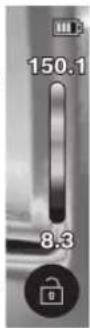
To determine the temperature of a specific area, guide the measuring tool so that the crosshair with the temperature reading (m) is aimed at the desired point or area. With automatic settings, the color spectrum of the scale is distributed linearly (= evenly) across the entire measuring range within the maximum and minimum temperatures.
The measuring tool displays all temperatures measured within the measuring range in relation to each other. If, for example, in one area of the color image, heat is shown in bluish tones in the color palette, this means that the bluish areas in the current measuring range belong to the colder measured values. Nevertheless, these areas can be in a temperature range where the temperature, under certain circumstances, can cause injuries. Therefore, always observe the temperature shown on the scale or directly at the crosshair.
Functions
Follow the information on navigating through the various menus (see "Navigating through the various menus", Page 330)

Illumination of the measuring object
The measuring tool is equipped with a work light (4). It is intended to illuminate the direct work area of the measuring tool when taking pictures; it is not intended for continuous illumination.
To switch the work light on/off, call up the left side bar. Scroll to the menu item / and confirm the option. If the work light is switched on, this is shown in the status bar.
After 2 minutes, the light is automatically switched off to avoid affecting the measuring accuracy.
You can set the automatic switch-off time in the menu by selecting .
Overlaying the thermal image with the real image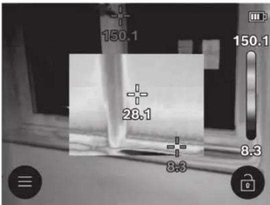
To make orientation easier (= assigning a spatial image to the displayed thermal image), the real image can be added in the smoothed temperature areas.
Note: The overlay of the thermal image with the real image is accurate at a distance of 1 m. At other distances to the measuring object, the real image is offset relative to the thermal image. This offset can be compensated for using special Bosch apps. Information on the apps and their suitability can be found on the product page of the measuring tool or at www.bosch-professional.com/thermal.
The measuring tool offers the following options:
- 100% infrared image
Only the thermal image is displayed.

- Transparency
The thermal image is transparent and overlaid on the actual image. This makes it easier to identify objects.
To activate/deactivate the setting, open the left sidebar and scroll to the menu item
/ . Confirm your selection by pressing the multifunction button (17) in the middle.
- Picture-in-picture
The thermal image is cropped, and the surrounding area is shown as the actual image. This setting makes it easier to assign the measured area to a specific location.
To activate/deactivate the setting, open the left sidebar and scroll to the menu item
/ . Confirm your selection by pressing the multifunction button (17) in the middle.
Color adjustment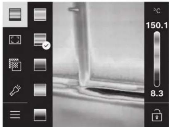
Depending on the measurement conditions, different color palettes can make it easier to analyze the thermal image and display objects and situations more clearly on the screen. This does not affect the measured temperatures. Only the representation of the temperature values changes.
To change the color palette, open the sidebar and scroll to the menu item "Color palette". Confirm your selection by pressing the multifunction button (17) in the middle.
Scale locking
The color distribution in the thermal image is performed automatically, but the scale can be locked by pressing the function button (17) on the right, then in the middle. This allows you to compare thermal images recorded at different temperatures (e.g., when checking several rooms for thermal bridges) or to eliminate an extremely cold or hot object from the thermal image that would otherwise distort the image (e.g., a radiator as a hot object when looking for thermal bridges).
To enable automatic scale setting, call up the right side bar and press the multifunction button (17) in the middle. The temperatures are then distributed dynamically and adapt to the measured minimum and maximum values.
Main menu
Call up the left side bar (see "Navigating in the various menus", Page 330). To access the main menu, press the multifunction button (17) in the middle.
- In this menu item, you can delete saved images individually or all at once.
-
- (a)
For the most common materials, you can choose from saved emissivity levels. To make searching easier, the values in the emissivity catalog are grouped. In the menu item, first select the appropriate category, then the appropriate material. If you know exactly the emissivity of the object you are measuring, you can enter its numerical value in the menu item.
- (b)
Setting this parameter can improve the measurement result, especially when materials have low emissivity (= high reflectivity). In some situations (especially indoors), the reflected temperature corresponds to the ambient temperature. You must adjust this value if objects with highly fluctuating temperatures near highly reflective objects can influence the measurement. To do this, press the multifunction button (17) on the left or right.
-
To maintain high accuracy over the entire measurement range, measurements are taken in 2 temperature ranges. With the measurement function activated, the measuring device automatically selects the appropriate temperature range based on the temperature distribution in the thermal image. At that time, it is evaluated how many measurement values are above the set temperature threshold. If you need to measure very small but hot objects, a low temperature range that is unsuitable for high temperatures may be selected. You will recognize this by the symbol \~ in front of the temperature reading. In such a case, switch to the measurement function <100 °C ... 450 °C> or <-20 °C ...
100 °C>, for which the color distribution corresponds to the set temperature range. The setting on the scale is marked with an arrow up or down.
-
• (m): /
The point is displayed in the middle of the thermal image; it shows the temperature value measured at this location.
- (n): /
The hottest point (= measurement point) in the thermal image is marked with a red cross. This facilitates the search for critical areas (e.g., disconnected contact terminals in a distribution board).
- <Cold spot> (I): /
The coldest point (= measurement point) in the thermal image is marked with a blue cross. This facilitates the search for critical areas (e.g., leaky window areas).
• (i): /
- (c): <|J.>/
The average temperature (c) is displayed at the top left of the thermal image (the average temperature of all measured values in the thermal image). This can help you determine the reflected temperature.
-
•
In this menu item, you can adjust the intensity of the display backlight.
•
In this menu item, you can select the time interval after which, if no button is pressed, the work light is switched off.
-
In this menu, you can select the time interval after which, if no button is pressed, the measuring device automatically switches off. Automatic switch-
off can also be deactivated; in that case, select .
In this menu, you can change not only the time and date settings, but also the corresponding formats.
In this menu item, you can select the language used in the displays.
In this menu item, you can restore the measuring tool to its factory settings and permanently delete all data. Depending on the circumstances, this may take a few minutes. Then press the multifunction button (17) on the right if you want to delete all files, or the multifunction button (17) on the left if you want to cancel the operation.
In this menu item, you can call up information about the measuring tool. There you will find the serial number of the measuring tool and the version of the installed software. In addition, you can find more information about the measuring tool and software updates.
To exit any menu and return to the standard display screen, you can also press the measurement button (6).
Updating the measuring tool software
If necessary, you can update the measuring tool software via the USB Type-C® interface. For more information, see:
www.bosch-professional.com/thermal-update.
Documentation of measurement results
Saving measurement results
After switching on, the measuring tool immediately starts measuring and continues to do so until it is switched off.
To save an image, point the camera at the desired measuring object and press the measuring button (6). The image is stored in the internal memory of the measuring device. The measurement is held and displayed on the screen. This way you can carefully evaluate the image and adjust it further (e.g., the color palette). If you do not want to save the held image, press button (6) again to return to measuring mode. If you want to save the image in the internal memory of the measuring device, press the multifunction button (17).
Recalling saved images
To recall saved images, proceed as follows:
– After saving, immediately press the multifunction button (17) in the middle again. The preview of the most recently saved photo is shown on the screen.
– You can optionally recall saved photos in the menu item .
– To view saved thermal images, press the multifunction button (17) to the right or left.
334 | Lithuanian
Not only the thermal image but also the visual image was saved. To recall it, press the multifunction button (17) at the top or bottom.
After 5 s, the measuring device switches to full image view. In full image view, the top bar is switched off after s so that you can evaluate all details of the thermal image. By pressing the multifunction button (17) at the top and bottom, you can switch between images.
Deleting saved images
To delete specific or all thermal images, press the multifunction button (17) in the middle. A submenu opens.
- Here you can choose whether you want to delete only this photo or all photos. Confirm the option by pressing the multifunction button (17) in the middle.
In the <Delete all photos> item, you can select <Delete all> or . Confirm the option by pressing the multifunction button (17) in the middle.
- In this submenu, you can also view information about the emission level and the reflected temperature.
Fragments of image files remain in memory and can be reconstructed. To delete them permanently, select → <Factory reset> in the main menu.
Data transfer
Data transfer via USB interface
Open the cover of the USB Type-C® port (11). Connect the USB Type-C® port (12) of the measuring tool to your computer using the supplied USB Type-C® cable (16).
Switch on the measuring tool with the on/off button (18).
On your computer, open the file browser and select the storage device GTC_450. The files saved in the internal memory of the measuring tool can be copied, moved to your computer, or deleted.
To end the desired operation, disconnect the storage device from the computer in the standard way and switch off the measuring tool again with button (18).
Note: Always disconnect the storage device from your operating system first (eject the storage device), otherwise the internal memory of the measuring tool may be damaged.
Disconnect the USB Type-C® cable and put the cover back on (11). Always keep the USB interface cover closed to prevent dust and splashing water from entering the housing.
Note: Connect the measuring tool to a computer only via the USB cable. Connecting to other devices may damage the measuring tool.
Note: The USB Type-C® interface is intended only for data transfer. It cannot be used to charge batteries or rechargeable batteries.
Thermal image processing
You can process the saved thermal images with the special Bosch app. Information about the apps and their compatibility can be found on the product page of the measuring tool or at www.bosch-professional.com/thermal.
Fault – Cause and remedy
Faults – Cause and Remedy
If the device trips, it will restart automatically and can then be used again. If this does not happen and error messages persist, the overview below will help you.
Fault Cause Remedy
| Matavimo prietaiso negalima jjungti. | Akumuliatorius/baterijos išsikrove | Įkraukite akumuliatorių arba pakeiskite baterijas. | |
 | Akumuliatoriaus/baterijos ge-dimas | Pakeiskite akumuliatorius ar baterijas. | |
 | Akumuliatorius/baterijos per šiltos arba per šaltos | Palaukite, kol nusistovės pastovi akumuliatoriaus temperatū-ra, arba akumuliatorių ar baterijas pakeiskite. | |
 | Matavimo prietaisas per šiltas arba per šaltas | Palaukite, kol nusistovės pastovi matavimo prietaiso tempera-tūra. | |
 | Pažeista USB jungtis arba USB kabelis | Patikrinkite, ar matavimo prietaisą galima sujungti su kitu ko-mpiuteriu. Jei ne, matavimo prietaisą išsiųskite j įgaliotąBosch klientų aptarnavimo tarnybą. | |
| Matavimo prietaiso negalima sujungti su kompiuteriu. | Nuoroda:visada naudokite USB kabelį, kuris jeina į tiekiamą komplektą. | ||
Fault Cause Remedy
| CR1225 |
Flat battery
Replace the flat batteries (see "Replacing the flat batteries (see Fig. C)", page 335). Confirm your selection by pressing the multifunction button (17) in the middle.
Explanations of terms
For more information, see www.bosch-professional.com/thermal.
Infrared radiation
Infrared radiation is electromagnetic radiation emitted by every body above 0 Kelvin (−273 °C). The amount of radiation depends on the body's temperature and its emissivity.
Emissivity
The emissivity of an object depends on the material and its surface structure. It indicates how much infrared radiation an object emits compared to an ideal heat-radiating object (e.g., a black body, emissivity ε = 1) and therefore its value ranges from 0 to 1.
Thermal bridge
A thermal bridge is a location in a building's exterior wall where, due to design features, there are higher local heat losses.
Thermal bridges can increase the risk of mold.
Reflected temperature / object reflectivity
Reflected temperature is radiated heat that does not originate from the object. Depending on the structure and material, ambient emissions are reflected in the measured object and distort the temperature results.
Distance to the object
The distance between the measuring object and the measuring device affects the size of the measured area at the point. The greater the distance to the object, the larger the objects you can encompass.
| Atstumas (m) Infraraudonujų spindulių taško dydis (mm) | Infraraudonujų spin- dulių srities plotis × aukštis (m) |
| 0,30 1,14 ~ 0,29 × 0,22 | |
| 0,55 2,08 ~ 0,53 × 0,40 | |
| 1,00 3,79 ~ 0,97 × 0,73 | |
| 2,00 7,58 ~ 1,94 × 1,46 | |
| 5,00 18,95 ~ 4,85 × 3,64 |
Maintenance and service
Maintenance and cleaning
Store and transport the measuring device only in a suitable case, e.g., the original case.
The measuring device must always be kept clean. A contaminated infrared sensor (5) can impair measurement accuracy.
When cleaning the measuring device, care must be taken to ensure that no liquids enter it under any circumstances.
Do not clean dirt from the infrared sensor (5), camera (3), work light (4), and laser beam exit aperture (2) with pointed objects. Do not wipe across the infrared sensor and camera (risk of scratching).
Clean the surface around the laser beam exit aperture regularly. Make sure that no lint remains stuck after cleaning.
If you wish to have your measuring device recalibrated, please contact an authorized Bosch customer service center.
In case of repair, send the measuring device in the original case.
The measuring device contains no parts that require maintenance by the user. Opening the housing cover may irreparably damage the measuring device.
Replacing the button cell (see figure C)
Open the cover (11).
Unscrew the screw (10) of the tablet-shaped element holder. Pull the tablet-shaped element holder (9) out of the measuring tool. Replace the tablet-shaped elements. Then insert the tablet-shaped element holder and firmly screw in the screw (10) again.
After-Sales Service and Consulting Service
The After-Sales Service department will provide answers to questions regarding the repair, maintenance, and spare parts of your product. Detailed drawings and information about spare parts can be found here: www.bosch-pt.com
If you have questions about our products and accessories, the Bosch Consulting Service specialists will be happy to advise you. When seeking information and ordering spare parts, always specify the 10-digit product number found on the nameplate.
Lithuania
Bosch Tool Service
Information Service: (037) 713350
Tool Repair: (037) 713352
Fax: (037) 713354
Email: service-pt@lv.bosch.com
You can find other service addresses here:
www.bosch-pt.com/serviceaddresses
Transportation
The transport of recommended lithium-ion batteries is subject to the regulations governing the transport of dangerous goods.
336 | Lithuanian
These provisions. The user is allowed to transport the battery by air without any restrictions.
If third parties are involved in shipping (e.g., air transport, freight forwarding companies), special requirements for packaging and labeling must be observed. A dangerous goods transport specialist must be involved in preparing the shipment.
Only send batteries with an undamaged housing. Tape over the contacts and pack the battery so that it cannot move in the packaging. Please also comply with national legal regulations.
Disposal

Measuring instruments, batteries/rechargeable batteries, accessories, and packaging must be disposed of in an environmentally friendly manner.
Do not dispose of measuring instruments, batteries, and rechargeable batteries in household waste!
For EU countries only:
Measuring instruments that are no longer usable and damaged or worn-out batteries/rechargeable batteries must be disposed of separately. Use the designated collection systems.
Improper disposal of waste electrical and electronic equipment can have harmful effects on the environment and human health due to potentially hazardous substances contained in them.
Batteries/rechargeable batteries:
Lithium-ion:
please follow the instructions in the transport section (see "Transport", page 335).
An unsuitable battery. The battery can burn or explode. Ensure ventilation and consult a doctor if you have complaints. This can cause personal injury.
Flammable liquid leaks from the battery. Avoid contact. Rinse with water if unintentional contact occurs. If the liquid gets into the eyes, consult a doctor in addition. Leaking battery liquid can cause skin irritation or burns.
Sharp objects such as nails or screws, or the effect of external forces. This can lead to an internal short circuit and the battery burning, emitting smoke, exploding, or overheating excessively.
Be careful to keep the device away from paper clips, coins, and other small metal objects that could bridge the contacts. A short circuit between the contacts may cause burns or fire.
The manufacturer protects the battery from overcharging. Use only the specified charging method.
It is recommended to use only the charger provided by the manufacturer. There is a risk of fire if chargers intended for one type of battery are used with another type.
Protect the device from heat, including prolonged exposure to sunlight, as well as from fire, dirt, water, and moisture. There is a risk of explosion and short circuit.
Fumes may be released if the battery is damaged. Avoid inhalation.

Safety Instructions
Read all instructions and warnings before using the measuring device. Use the device safely and without risks. If the device is used in a way not specified in the instructions, it may adversely affect

Protective measures for the measuring device. Do not remove warning labels from the device.
Keep the instructions in a safe place and attach them to the device if you give it to someone else.
Using the device with other equipment or in a different manner may result in hazardous exposure to laser radiation.
The laser is identified in the device illustration on the diagram page.
For laser safety, affix the label in your language before first use. Use the battery only in products
Do not point the laser beam at people or animals, and do not stare into the beam.
The laser beam can cause eye damage, accidents, or injuries. Avoid direct eye exposure.

Turn it off immediately and move your head away from the laser beam.
Do not cover
with a warning sign
written on the sign
◀ Press on the eye, then
on the laser device.
◀ (Laser (accessories)
◀ Laser (accessories) such as glasses
◀ Only by technicians
◀ Without capacity
◀ Range exposed to danger
or its opening. There is a risk
Warning
Make sure that the button battery does not reach children's hands. The battery is dangerous.

It must never be
inserted into any body opening. If you suspect that you have swallowed the button battery or inserted it into any body opening, seek medical attention immediately. Swallowing the button battery can cause serious internal burns and may lead to death within two hours.
Replace it in a technically sound manner. There is a risk of explosion.
Like sunglasses. Laser viewing goggles are used to see the laser beam better, but they do not protect against laser radiation.
Sun or goggles for use during military operations. Laser viewing goggles do not provide complete protection from ultraviolet rays, and they also reduce the ability to distinguish colors.
◀ Dispose of button batteries or
Only qualified personnel should use genuine spare parts. This ensures the safety of the measuring tool.
Do not leave the laser unattended. It may cause unintentional injury to you or others.
Explosion, fire, and chemical hazards. Do not use in potentially explosive atmospheres or near flammable gases or vapors. The tool may produce sparks that could ignite these gases or vapors.
Electric shock hazard.
Product description and performance
Pay attention to the figures in the illustrated section of the instructions.
Intended use
This thermal imaging camera is used for non-contact surface temperature measurement. The thermal image displayed indicates the temperature distribution of the object being measured, allowing temperature differences to be shown with color contrast. With proper use, surfaces and objects can be inspected without contact to identify clear temperature differences, highlighting parts and/or any other specific points, including:
Heating pipes,
Underfloor heating) in floors and walls.
or connection terminals
excessive due to bearing damage). The thermal camera is not suitable for measuring gas temperatures. The thermal camera must not be used for medical purposes. It can be used for veterinary applications. www.bosch-professional.com/thermal The thermal camera is designed for indoor and outdoor use. This product is a consumer laser product and complies with EN 50689. The laser pointer of this thermal camera is intended for direct alignment of the camera's field of view for image capture and is not to be used as a permanent working pointer. The laser point must not be used as a laser level. Its use is limited to marking the surface of the thermal camera.
Illustrated components
The numbering of the illustrated components refers to the diagrams of the measuring tool on the graphic pages. (1) Protective cover (2) Laser beam outlet (3) Optical camera (4) Work light (5) Infrared sensor (6) Pause/start button for measurement (7) Memory card slot (8) Laser warning label (9) Battery holder (10) Battery compartment screw (11) Cover for USB and battery compartment (12) USB Type-C® a) (13) Laser button
mentioned in this operating manual. Do not use other coin batteries or other power sources.
Do not short-circuit the battery. The coin battery may not be sealed against leakage and may explode or ignite, causing injury to persons.
Dispose of them properly according to regulations. Empty or damaged coin batteries may leak and cause injury or damage.
Do not overcharge or throw them into fire. The coin battery may not be sealed against leakage and may explode or ignite, causing injury. Heating pipes and hot surfaces (e.g., radiators) should not be touched or disassembled. The coin battery may become unsealed and leak, potentially causing fire or injury. Moving or damaged machine parts (e.g., water heater). Leaked battery fluid in contact with water may produce hydrogen, which could lead to fire, explosion, or injury.
Close the battery compartment properly and completely. Remove the coin battery and ensure the thermal camera is repaired.
This can cause high temperatures to be displayed in a certain color, which is associated with low temperatures. Such systems can lead to burns.
This occurs when the set emissivity matches the actual emissivity of the object. Objects may be displayed at higher or lower temperatures, which could pose a risk if touched.
High-performance CO2 lasers directly. This may damage the detector.
Protect the camera and infrared lens from moisture, snow, and heat sources. Water droplets on the lens or dirt can lead to incorrect measurement results. Also, extreme ambient conditions and other weather factors can cause incorrect measurements. Objects may be displayed at higher or lower temperatures, which could pose a risk if touched.
Coin battery
Coin battery, and
◀ The case that branched
◀ Battery temperature level
And damage to the battery
The following case touches
Capacity if it cannot
In a thermal image
Important settings for the degree
Sunlight or
◀ Especially ranges
339
(b) Bryan reflected temperature
(c) Bryan average temperature
(d) Memory full symbol
(e) Work light symbol
(Laser symbol)
(g) Oil level indicator
(h) Maximum surface temperature indicator in the
measurement range
(i) Scale
(j) Surface temperature indicator in the
measurement range
(5) Temperature scale symbol fixation (5)
(1) Indicator Nicplate LaRade (nmodj)
Aiming indicator with temperature Bryan (m)
(1) Dew point indicator (typical)
(5) Menu symbol
(14) Resolution button / battery adapter
(15) Battery
USB Type-C® cable (16)
(17) Multifunction button
(18) Start/Stop button / Return button
(19) Display unit
(20) Serial number
(21) Battery adapter case
(b) Batteries (22)
(23) Protective cover for adapter
.USB Implementers Forum
These are trademarks of (a)
b shown in the drawing
Not included in the standard delivery scope.
Display elements
(a) Emission level indicator
Technical data
| GTC 12V-450-13 | كاميرا التصوير الحراوي |
| 3 601 K83 900 | رقم الصنف |
| 192 × 256 | دقة مستشعر الأشعة تمت الحمراء |
| 50 ≥ | المساسية المراية(A) |
| 14-8 | المجال الطيفي |
| 42° × 55,6° | (FOV)(A) |
| 3,79 | الدقة المكن Initiative(IFOV) |
| 0,5 ≤ | (ابعد البؤري(A) |
| ثابئة | البؤرة |
| 9 ≥ | معدل تمديد الصورة الحراية |
| 450+...20- | (ηطاق قياس درجة حرارة الأسطع(A) |
| 2 ± % 2 ± | (C(B)(A)dقة قياس درجة حرارة السطح(D)ρ° 100+ ≥ ... ρ° 0 < (E)ρ° 100+ < |
| 0,1 | الدقة المراية |
| TFT | نوع الشاشة |
| "2,8 | مقاس الشاشة |
| 360 × 480 | دقة وحددة العرض |
| 480 × 640 2 ميبا يكسل (لقطة شاشة) | دقة الكاميرا البصرية المدجمة |
| .jpg | صيغة الصور |
| 1 × 1 صورة حرارية واحدة | العناصر المف GUظة مع كل عملية حفظ |
| 1 × 1 صورة بصرية حقيقية واحدة شاملة قيم درجات(الجرارة (بيانات تعريفية) | |
| 500 | أقصى عدد للصور في الذاكرة 동اخلية للصور |
| 2000 متر | المد الأقصى لارتفاع الاستفادام فوق الارتفاع المرجعي |
| 2F) | درجة الاتساغ تبعا للمعيار 1IEC 61010-1 |
| % 90 | (المد الأقصى لرطوبة الهواة النسبية(A) |
| 2 | فئة الليزر |
340|Arabic
| GTC 12V-450-13 | كاميرا التصوير الحراوي |
| 660-645 مللي واط، زاوية كاملة 1,5 | طراز الليزر تفamoto شعاع الليزر الإimedاد بالطاقة |
| 12 | - |
| LR6 (AA) 1,5 × 4 | - |
| HR6 (AA) 1,2 × 4 | (مراكم (نيكل هيدريد مع مهايئ bankruptات)までの تشغيل) |
| 8 ساعات | (المركم (أيوئات ليئيوم) بطاريات (المنجنيز القلوي) |
| 4 ساعات | (وقت نظام الإimedاد بالطاقة USB قياسي USB |
| CR1225 (بطارية ليئيوم 3 فлот) | USB |
| 2.0 | (الوزن) |
| USB Type-C® | (الأبعاد (الطول × العرض × الارتفاع) |
| 0,354 | (فئة الحماية (باستثناء Pres/الbart Airlines، في الوضع) |
| 209 × 79 × 89 | (القائم) |
| IP54 | (درجة المراurchase المحيطقة الموصى بها عند الشمن درجة المراurchase المحيطقة المسموع بها |
| 35+ ... ρ°0 ρ°50+ ... ρ°10- ρ°50+ ... ρ°20- ρ°70+ ... ρ°20-GBA 12V... | (عند التشغيل) |
| 12...GAX 18... | (أجهزة الشمن الموصى بها |
(AY) According to standard 5585 (average value)
B) At a MediaType temperature of 20-23°C and a spot degree < 0.95, with a measuring distance of 1 meter, and an operating time of < 5 minutes.
And a time of 150 mm, with the work light and laser turned off.
C) By electricity to the device connected to the use (for example, the GK, distance, ambient temperature)
(D) Applies to the central point, for all pixel units with an electric deviation of up to 1°C
E) Applies to the central acupuncture, for all other southeastern bank units with an electric deviation of ±1%
(F) No conductive dirt occurs, but in some cases condensation may cause conductive dirt, temporarily.
G) With the work light off and the screen brightness at medium level
(H) According to the center used
( ) At an external temperature of 20-30°C
L) Weight without center/battery adapter/batteries
With battery (K) or battery adapter GBA 12V 2.0Ah
To clearly identify the measuring tool, refer to the serial number (20) on the nameplate.
Others are compatible with lithium-ion centers that can be used in your measuring tool. Note: Lithium-ion accumulators are shipped partially charged according to international transport regulations. To ensure full battery performance, fully charge the battery before first use. To insert the supplied battery (15), push it into the battery compartment (7) until a click is heard. To remove the battery (15), press the release buttons (14) and pull the battery out of the battery compartment (7). Do not use force during this process.
Power supply for the measuring tool
With electric current
The measuring tool can be operated with Bosch lithium-ion batteries.
Nickel metal hydride batteries available on the market.
Operation with the battery
(see figure)
Use only the chargers listed in the
technical specifications. These chargers are
not suitable for other tools and can cause severe damage
(see figure)
The measuring tool can be operated with alkaline manganese batteries or nickel metal hydride rechargeable batteries. Insert the batteries into the battery compartment.
For use with tools
Starting operation
When starting for the first time
When operating the measuring tool for the first time or after resetting to factory settings, some basic settings must be made. Select the desired values by pressing the multi-function button (17) down, up, left, or right. Press the multi-function button (17) in the center to confirm your selection. Once you have confirmed your choice, the second setting will appear on the display. The total number of settings and the number of remaining settings are shown at the top of the status bar. The following basic settings are made:
Bosch measuring tools must not be used with electrical tools.
To insert the batteries, insert the battery holder (21) into the battery compartment (7). Place the batteries according to the picture on the protective cover (23) into the holder. Slide the protective cover onto the holder until it clicks into place. To remove the batteries (22), press the release buttons (14) on the protective cover (23) and pull off the cover. Remove the batteries. To remove the holder (21) from the battery compartment, insert your finger into it and pull it out while pressing lightly against its side wall. To remove it from the measuring tool. Always replace all batteries or rechargeable batteries at the same time. Use only batteries or rechargeable batteries of the same type and with the same capacity.
- Remove the batteries from the measuring device. - Always replace all batteries or rechargeable batteries at the same time. Use only batteries or rechargeable batteries of the same type and with the same capacity.
- ◀ About the measuring device
Switching on and off
For the measuring device, open the protective cover (1). While working, make sure that the laser beam is not directed at people and that the laser beam is not covered or blocked. To switch the measuring device on, press the on/off button (18). The display (19) shows the battery status. For switching on. ]. ]. ]. ]. ]. ]. ]. ]. ]. ]. ]. ]. ]. ]. ]. ]. ]. ]. ]. ]. ]. ]. ]. ]. ]. ]. ]. ]. ]. ]. ]. ]. ]. ]. ]. ]. ]. ]. ].].
When not in use for a long time. Batteries and rechargeable batteries may corrode if they are left in the measuring device for a relatively long time.
About the measuring device
Notes for working with the device
Clean the device with a dry cloth and water. Do not clean the device except within a temperature range between -20°C and 50°C. Do not leave the device in the car, for example, in summer. If the operating time after charging decreases significantly, this indicates that the battery is consumed and must be replaced. Follow the instructions when disposing of the device.
Protect
from direct sunlight.
from moisture and rays
; from extreme temperatures or
severe temperature fluctuations. Do not leave it for a long time in the car, for example. In case of temperature changes, let the measuring device acclimate to the temperature for some time before switching it on. Extreme temperatures or severe temperature fluctuations can damage the measuring device.
The maximum operating temperature of the measuring device.
In case of large temperature fluctuations, the acclimatization time can be up to 60 minutes. This can be the case, for example, if you store the measuring device in a cold car and then take a measurement in a warm room.
342|Arabic
The temperature values displayed are accurate only for objects
that match the set emissivity. For all
other objects (which have different emissivities),
the displayed color differences can be used as an indication
of relative temperature variations.
Notes on measurement conditions
Highly reflective or shiny surfaces (e.g., glossy tiles
or polished metals) can lead to significantly
incorrect results or be negatively affected. If necessary,
cover the measurement surface with a dark, matte adhesive tape
that conducts heat well. Wait
for the tape to reach the same temperature as the surface.
For reflective surfaces, ensure that the measurement
is taken in a way that avoids reflected radiation.
Reflections from other objects can lead to incorrect results.
For example, in measurements
of vertical surfaces, reflections from your body
can negatively affect the measurement process.
In the case of a flat surface, the
emissivity and body temperature (reflected value) may be displayed, which
does not correspond to the actual temperature of the measured surface
(the emitted value or the actual value of the surface in question).
Measurements cannot be taken through
transparent materials (e.g., glass or clear plastic) in principle.
The more stable and consistent the measurement conditions, the more
accurate and reliable the measurement result. This applies not only to
extreme temperature fluctuations in the ambient
conditions, but also to extreme fluctuations in
Measured body temperatures can be lower by one degree
of accuracy.
Also, infrared temperature measurement
can be negatively affected by smoke or steam/humidity
or dusty air.
Guidelines for achieving better measurement accuracy:
To minimize interference factors between you and the measurement surface
to a minimum degree.
Measurement, especially if the air is polluted or contains
many particles. Let the room return to its normal moderate temperature after ventilation.
Extend the measurement position
animals and do not direct your gaze at the laser beam
even from a distance.
The measuring tool is equipped with a laser for setting the measurement position.
Press and hold the laser button (13). The
laser symbol (f) appears in the status bar, and a red circle
around the aiming indicator (m). The laser and the aiming
indicator are perfectly aligned at a distance of 1 meter. When
you release the laser button (13), the laser turns off.
Navigating the different menus
Navigating the different menus of the measuring tool:
Press the multi-function
button (17) in the center or on the left side.
Menu bars appear on the right and left of the
screen, and the main menu is highlighted.
Left menu / navigation in the
main menu: Press the multi-function
button (17) up, down, left, or right.
Left or right: Compact-
Press the multifunction button (17) to the left or right.
Submenu: Compact-
Press the multifunction button (17) in the middle.
Top menu: Press-
(18) the back button
Measurement settings
Setting the emissivity for temperature measurements
Brightness
The emissivity of an object depends on its material and structure.
It indicates the amount of infrared radiation
emitted by the object in question
compared to an ideal thermal radiator (black body, emissivity
ε = 1). Accordingly, its value ranges between 0 and
1.
To extend the surface temperature, the infrared radiation emitted by the target is measured
naturally, without any contact. To obtain accurate measurements
you must review the set emissivity in the measuring device
before each measurement and adjust it to the measuring object
if necessary.
The emissivity values preset in the measuring device are
reference values.
You can choose one of the preset emissivity values
or enter a precise value. Adjust the emissivity
using the menu
(see "Main menu", page 344).
Accurate temperature readings are only possible if the emissivity
is matched to the object. In enclosed spaces, ventilate the area before
measuring.
the set emissivity and the object's emissivity.
The emissivity.
The higher the emissivity, the greater the influence of the measured temperature.
Therefore, always
adjust the emissivity to match the laser spot or
the emissivity setting. Adjust the reflected temperature.
<Measurement menu
← parameters>
(see "Main menu", page 344)
Apparent color differences displayed by multiple
measurements may be due to differences in temperatures and/or
emissivities. If there are
significant differences in emissivities, the displayed
temperature may differ from the actual temperature
significantly.
If there are multiple measurement objects with different materials
or a different structure in the measuring range, then
overlay of the thermal image and the real image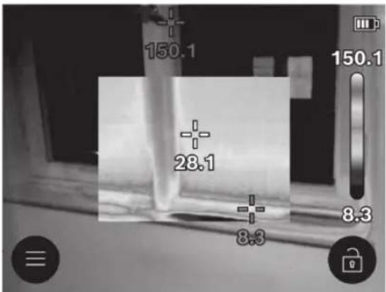
for better orientation = spatial assignment of the displayed thermal image) can additionally be inserted into the usual thermal images a real visual image.
Note: The overlay of the real image and the thermal image is exactly aligned at a distance of 1 meter. (If the distance to the measuring object differs, a shift occurs between the real image and the thermal image due to the principle of operation.) (This shift can be compensated for via the special Bosch applications.) (You can find information about the applications and connection options on the product page of the measuring tool or on the website www.bosch-professional.com/thermal.
The measuring tool offers the following display modes:
Only the thermal image is displayed.
Displaying the temperature levels with the help of the scale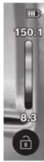
On the right side of the display, a scale (i) is shown. The values at the top and bottom depend on the maximum (h) or minimum (j) temperature in the thermal image. 19.99% of the total pixels are evaluated in the scale. The color gradations for the temperature values are distributed evenly in the image (vertically).
With the help of the different color gradations, you can thus determine the temperatures within the two limit values; for example, any temperature that lies exactly between the maximum and minimum value is assigned to the middle color point in the scale.
To measure a specific temperature or range, move the measuring tool so that the aiming indicator with the temperature (m) is pointed at the desired point or range. In the automatic mode, the color range of the scale is continuously distributed over the entire range between the maximum and minimum temperature evenly (i.e., equally). The measuring tool collects the measured temperatures in a range that is arranged in a certain order. If, for example, in a color display, the indication of the temperature in the color palette is blue, this means that the blue ranges are values with relatively cold temperatures in the current range. However, these ranges can also be present in a temperature range that can lead to errors in some cases. Therefore, check the temperature shown in the scale or with the aiming indicator directly.

- Transparency
Functions
Please note the information regarding navigation in the various menus (see "Navigation in the various menus", page 342
Illumination of the measuring object


The measuring tool is equipped with a work light (4). It is intended for direct illumination of the measuring tool's work area for taking pictures and is not a permanent work lamp. To switch the work light on/off, call up the left side bar. Navigate to the menu item and confirm your selection. If the work light is switched on, this is shown in the status bar. The light switches off automatically after two minutes so that it does not affect the measurement accuracy. You can extend the automatic switch-off time in the menu. Under
The displayed thermal image is superimposed transparently over the real image. This allows for better recognition of objects. To enable/disable this setting, call up the left sidebar and scroll to the menu item "Visual image on/off". Confirm your selection by pressing the multi-function button (17) in the middle.
The thermal image is cropped and the relevant area is displayed as a real image. This setting improves the spatial resolution of the measurement points. To enable/disable this setting, call up the left sidebar and scroll to the menu item. Confirm your selection by pressing the multi-function button (17) in the middle.
Emissivity levels. Select the appropriate menu item and set the emissivity. If the emissivity is known, you can also set it as a custom value under the menu item "User defined".
This parameter can improve the measurement result, especially with materials with low emissivity and high reflectivity.
In some situations (especially in enclosed spaces), the reflected temperature often matches the ambient temperature. If there are highly reflective objects nearby that could affect the measurement, you can adjust this value. Navigate using the multi-function button (17) left or right.
To ensure a high level of accuracy across the entire measurement range, the measurement range is divided into two temperature ranges.
In the measurement function, the appropriate temperature range is selected automatically using the temperature distribution in the thermal image. During this process, the number of measured values that fall within a certain temperature range is counted. If very small, hot objects are measured, the high temperature range may be selected. This can be recognized by the symbol \~ in the temperature display. In this case, switch to the measurement function <100 °C ... 450 °C> and set the device to the appropriate scale.
A measurement point appears in the center of the thermal image and shows the measured temperature value at that point.
The hottest point (measurement pixel) is automatically marked in the measurement function with a color indicator in the thermal image. This makes it easier to find hot spots (for example, a loose connection in an electrical cabinet).
The coldest point (measurement pixel) is marked with a color indicator in the thermal image. This makes it easier to find cold spots (for example, unsealed gaps in a window).
The average temperature (c) appears in the thermal image on the display (average temperature of all measured values in the thermal image). This helps you determine the reflected temperature.
Color display adjustment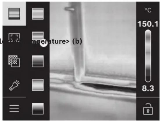
Different color palettes are used in the thermal image analysis to display objects or temperature differences more clearly on the display. The measured temperature values are not affected by this. Only the way the temperature values are displayed changes. To change the color palette, call up the left sidebar and scroll to the menu item "Color palette". Confirm your selection by pressing the multi-function button (17) in the middle.
Setting the scale
The color distribution in the thermal image is automatically adjusted, but it can also be adjusted manually by pressing the function button (17) to the right and then in the center. This allows comparison between thermal images captured under different thermal conditions.
- m * (e.g., when monitoring several locations Center spot (m): @N/«OFF» (thermal) or the emissivity of an object in the thermal image as it affects its distortion (e.g., a heating device as a hot object at the memorial)
- (n): / the scale. To return to automatic mode, press the right button and then press the multi-function button (17) in the center. The scale levels will then be adjusted dynamically again and adapt to the measured minimum and maximum values.
- (l): / the main menu Press the left button (see "Navigating the menus", page 342) to access the main menu. Press the multi-function button (17) in the center.
- (i): / - (c): / one.
- <Measurement pair - (a)
Stored emissivity levels are available for selection with some of the most commonly used values. To facilitate the search, the values are grouped in a catalog.
345
For the internal settings of several capacities, press the multi-function button (17) in the center.
Recalling stored images
To recall stored thermal images, do the following: - Press the multi-function button (17) in the center again immediately after saving. A preview image of the last saved image appears on the screen.
. Within the menu item
Press the multi-function button (17) to the right or left. In addition to the thermal image, the visible image is also saved. To display this image, press the multi-function button (17) up or down. After 5 seconds, the measurement tool switches to the full screen view. In the full screen view, the title bar information is hidden after a few seconds so you can see all details of the thermal image. By pressing the multi-function button (17) up or down, you can navigate between the views.
Deleting saved images
To delete individual thermal images or all thermal images, press the multi-function button (17) in the middle. A submenu appears.
Image only or all images. Confirm the deletion by pressing the multi-function button (17) in the middle.
You can make a selection when choosing. Or by pressing the multi-function button (17) in the middle.
In this submenu, you can view information about the emission degree and the reflected temperature.
Excluding. The image data in the memory can be configured. For final deletion, go to the main menu.
Data transfer
Data transfer via the USB interface. Open the cover (11) for the USB Type-C® port. Connect the supplied cable (16) to the personal computer. Turn on the device using the power button (18). On the computer, open the file manager and select the GTC_450 drive. The files stored in the internal memory of the device can be copied or transferred to the computer or deleted. After the desired operation is complete, disconnect the drive from the computer in the standard way, then turn the device off and on again using the power button (18).
You can adjust the brightness of the screen illumination in this menu item.
In this menu item, you can set the time interval after which the work light automatically turns off if no button is pressed.
- You can set the time interval after which the measuring device turns off automatically if no button is pressed. You can also disable the automatic shutdown by selecting the appropriate option.
In this submenu, you can change the date and time settings and set the time and date.
In this menu item, you can select the language used in the data.
In this menu item, you can reset the measuring device to the factory settings and delete all data permanently. This may take a few minutes in some cases. Press the multi-function button (17) on the right to delete all data. To cancel the operation, press the multi-function button (17) on the left.
In this menu item, you can call up information about the measuring device. You will find the serial number of the device and the software version. You can also find more information about the measuring tool and the software version there. To leave the desired menu and return to the standard display, you can also press the measurement button (6).
Extending the measuring tool
If necessary, the measuring tool's software can be updated via the USB Type-C® interface. You can find information on the internet at: www.bosch-professional.com/thermal-update
Saving measurement results
Saving measurement results
Immediately after switching on, the measuring tool starts measuring and continues until it is switched off. To save an image, point the camera at the object to be measured and press the measurement button (6). The image is then saved in the internal memory of the measuring tool. The measurement is then frozen and displayed on the screen. This allows you to view the image carefully and make subsequent adjustments (e.g., color palette). If you do not want to save the frozen image, press the measurement button (6) again to resume measuring. If you want to save the image in the memory
-
- <LED switch off after
- <Tool switch off after
-
-
-
-
346|Arabic
Note: The interface function is only for data transfer. It is not possible to charge the battery or rechargeable batteries via USB Type-C®.
Processing thermal images
You can perform subsequent image analysis of the saved thermal images using Bosch's special applications. You will find information about system requirements and compatibility on the product page of the measuring tool or on the Internet at www.bosch-professional.com/thermal.
Note: Always log out of the operating system first (shut down the unit), otherwise the internal memory of the measuring tool may be damaged.
(11) USB Type-C® and close the flap. Pull out the cable. Always keep the USB flap closed to prevent dirt or moisture from entering the device housing. Note: Do not connect the measuring tool to a PC via USB unless it is a computer with a USB port.
When connecting via USB to other devices, the measuring tool may be damaged.
Errors – Causes and Corrective Measures
If a malfunction occurs, the measuring tool performs a restart. This can be used to resume operation. In addition, the following overview will help you if persistent error messages appear.
Error
Recharge the battery or replace the batteries. The battery/batteries are empty. Measuring tool cannot be switched on.
Battery or batteries. Fault in the battery/batteries.
| دع المركم يبرد أو استبديل المركم أو الطائريات. | المركم/الطائريات شديددةالسخونة أو شديددةالبرزودة |  |
| دع عدة القياس ت Tekيف مع درجة limitations. | عدة القياس شديددةالسخونة أو شديددةالبرزودة |  |
| تحقيق مما إذا كان يتسني توصل عدة قياسبكميوتر شخصي أخرى. exponentially لم ينجج التوصيل، فأرسلي Boschعدة القياس إلى正確 مراكرز خدمة عملاء المعتمدة. | USB وصلة USB أو كامل بال tariffs |  |
The measuring tool cannot be connected to a personal computer. Note: Always use the USB cable included in the scope of delivery.
Change the emissivity, change the emissivity. The measurement is empty.
The emissivity (see figure) "C", page 347. Confirm the change using "OK" by pressing the function button (17) in the middle.
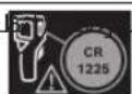
Compared to an ideal thermal radiator (black body, emissivity ε = 1) and accordingly its value ranges between 0 and 1.
Thermal bridge
A thermal bridge is a localized area on the exterior wall of a building where heat loss is increased due to design. Thermal bridges can lead to a risk of condensation.
Reflected temperature/object reflection
Meaning
Reflected temperatures are the thermal radiations that are not emitted by the object itself. Depending on the structure and material of the object, it reflects the surrounding radiation.
Interpretation of the measurement
You can find more information on the website www.bosch-professional.com/thermal
Thermal radiation
Thermal radiation is electromagnetic radiation that is emitted by every object whose temperature is above 0 Kelvin (-273°C). The intensity of the radiation depends on the temperature and the emissivity of the object.
Emissivity
The emissivity of an object depends on the nature and condition of the surface of this object. It indicates the amount of infrared radiation emitted by the object.
347
Website: www.bosch-pt.com
The customer service team at Bosch is happy to assist you if you have any questions about our products and their accessories. Please mention the product's article number when making any inquiries or ordering spare parts.
Morocco
Robert Bosch Morocco SARL
53, Rue Lieutenant Mohamed M
20300 Casablanca
Phone: +212 5 29 31 43 27
Email: sav.outillage@ma.bosch.com
You will find other service addresses under:
www.bosch-pt.com/serviceaddresses
Transport
The lithium-ion batteries contained are subject to the Dangerous Goods Legislation requirements. The user can transport them on public roads without any additional conditions. When transported by third parties (e.g., air transport or forwarding company), compliance with special requirements for packaging and labeling is required. In this case, when preparing the item for shipping, consult an expert for hazardous material. Only dispatch the battery if the housing is undamaged. Tape or mask off open contacts and pack up the battery so that it cannot move around in the packaging. Please also observe possible more detailed national regulations.
Disposal of the power tool
Power tools, accessories and packaging should be sorted for environmentally friendly recycling. Do not dispose of power tools into household waste!
Do not dispose of measuring tools and batteries/rechargeable batteries into household waste.

Batteries/rechargeable batteries:
Lithium-ion:
Please observe the notes in the section on transport (see "Transport", page 347).
on the object to be measured and thus falsify the actual temperature result.
The distance to the object
The distance between the measuring tool and the object affects the size of the area observed per pixel. As the distance to the object increases, you can observe objects with a larger area.
| العرض × الارتفاع | مقياس | المسافة |
| نطاق الأشعة تمت | بيكسل | (mتر) |
| الcorpاء (متر) | الأشعة تمت | (م) |
| (الممراء) | (mom) |
0.30 m: 1.14 m ~ 0.29 × 0.22 m
0.55 m: 2.08 m ~ 0.53 × 0.40 m
1.00 m: 3.79 m ~ 0.97 × 0.73 m
2.00 m: 7.58 m ~ 1.94 × 1.46 m
5.00 m: 18.95 m ~ 4.85 × 3.64 m
Maintenance and Service
Maintenance and Cleaning
Do not store or transport the measuring tool except in a suitable container, such as its original packaging.
Always keep the measuring tool clean. Dirt on the infrared sensor (5) may adversely affect measurement accuracy.
Liquids must not leak into the interior of the measuring tool.
Do not use sharp objects to remove dirt from the infrared sensor (5), the camera (3), the work light (4), or the laser exit aperture (2). Do not touch the infrared sensor or the camera (to avoid scratches).
Clean the surface of the laser exit aperture regularly and be careful not to leave lint during cleaning.
If you wish to recalibrate your measuring tool, please contact an authorized Bosch customer service center.
If repair is necessary, send the measuring tool in its original packaging.
There are no user-serviceable parts inside the measuring tool. Opening the housing may damage the measuring tool.
To replace the battery (see figure C), open the cover (11).
Loosen the screw (10) on the battery holder and pull the battery holder (9) out of the measuring tool. Replace the battery. Tighten the screw (10) after inserting the battery holder back in.
After-sales service and application service
Our after-sales service will answer your questions concerning the repair and maintenance of your product as well as spare parts. You will find the relevant drawings and information on spare parts
348 | فارسی
There are sparks generated by the measuring tool that can ignite dust or vapors in the air.
There is a short circuit.
If used improperly, the battery may emit vapors. The battery may catch fire or explode. In this case, ventilate the area; if you feel unwell, seek medical attention. Inhalation of these vapors can damage your respiratory tract.
Avoid any contact with the liquid. In case of accidental contact, rinse your hands or the affected area with water. If the liquid gets into your eyes, seek medical attention. Liquid ejected from the battery may cause skin irritation or burns.
External force may damage the battery. This may cause an internal short circuit, and the battery may catch fire, smoke, explode, or overheat.
Keep metal clips, coins, keys, nails, screws, and other small metal objects away from the battery, as they may cause a short circuit. A short circuit between the battery terminals can cause burns or fire.
Use only the battery specified by the manufacturer. This protects the battery against dangerous overloading.
Use only the charger specified by the manufacturer. If a charger designed for one type of battery is used to charge another type, there is a risk of fire.
Keep the battery away from heat, including prolonged exposure to sunlight, as well as fire, dirt, water, and moisture. There is a risk of short circuit and explosion.
Warning
WARNING: KEEP BUTTON BATTERIES OUT OF REACH OF CHILDREN. Button batteries are dangerous.
or other parts of the body. If you suspect that a button battery has been swallowed or has entered another part of the body, immediately


Persian
Do not modify or open rechargeable safety instructions. Danger◀
When clicking the battery, if it is deformed or leaking, or if the measuring tool is used in a manner not specified in the instructions, the protective measures may be impaired. Never cover the labels on the power tool. Keep them in good condition and when using the measuring tool, it may cause output

or methods other than those mentioned in this manual may lead to dangerous exposure to radiation.
for use or adjustment
A laser warning is emitted (shown in the display of the measuring tool on the screen) by a sharp object such as a nail or screwdriver or
, along with a label
If not, stick the warning label sent with the device in your country's language before first use.
. Laser in your language
Do not point the laser at people or animals, and do not look directly into the laser beam. This may cause eye damage, burns, or injury.

Immediately remove the laser from the product.
◀ Laser to the eye, sources
Charge the battery only with the recommended chargers.
Laser settings
Safety: Do not use. Laser viewing glasses are intended for better detection of the laser beam! However, they do not provide protection against the laser beam.
(glasses) as safety glasses
Do not use as sunglasses or while driving. Laser viewing glasses do not provide full protection against UV radiation and reduce color recognition.
(glasses) as safety glasses
Contact a professional service center and use only original spare parts. This ensures the safety of the measuring tool.
Measurement only
Unintentionally, others or yourself may be dazzled. Do not use laser measuring devices. It is possible
Do not use the tool without supervision
Never swallow button batteries or use in explosive atmospheres containing liquids, gases, or dusts; there is a risk of explosion.
Environment with potential
Product description and function
Refer to the illustrations at the beginning of the manual.
Intended use of the device
This thermal camera is intended for non-contact temperature measurement of surfaces. The thermal image displayed shows the temperature distribution in the field of view of the thermal camera, thus displaying temperature differences in distinct colors. With proper use, surfaces and objects can be checked without contact for temperature differences or abnormalities, so that installed components and/or weak points can be identified, including:
thermal bridges,
(for example, underfloor heating) in floors and walls,
for example, fuses or terminals,
for example, overheating due to defective bearings. The measuring tool is not intended for measuring gas temperatures. The measuring tool must not be used for medical purposes on humans. For information on veterinary use, please visit this website: www.bosch-professional.com/thermal. This power tool is intended for use in outdoor and indoor building environments. This product is a consumer laser product according to EN 50689. The work light of this measuring tool is not intended for direct illumination of the work area; it is intended for image recording and does not function as a permanent work light. Do not use the laser point as a laser pointer. These are only for marking the measuring surface.
Device parts images
The numbers of the device components shown in the image correspond to the measuring tool depicted in this manual. (1) Protective cover
(2) Laser beam outlet opening
(3) Eyepiece camera
(4) Work light
(5) Infrared sensor
(6) Measurement and save/start button
(7) Battery compartment
(8) Laser warning label
Consult a physician. Swallowing a button battery can cause internal burns and death within 2 hours.
There is a risk of explosion.
Use the instruction manual. Do not use other watch batteries or another power source.
Do not cause them to short-circuit. Watch batteries may leak, explode, catch fire, and injure people.
- Dispose of them properly. Empty watch batteries may leak hazardous substances (for example, if found) or injure people. Do not place them on active heating pipes or hot water pipes. Watch batteries may leak, corrode, catch fire, and injure people.
- Defective or damaged parts in the device - Do not. Watch batteries may leak, explode, catch fire, and injure people.
Do not expose to water. Leaked lithium may produce hydrogen in water, which can lead to fire, explosion, or injury.
If it does not close properly and completely, remove the button battery, do not use the power tool, and take action to repair it.
This can cause even high temperatures to be displayed as low temperatures. Contact with such surfaces can lead to burns.
It is important that the set surface temperature matches the actual surface temperature. Objects may be shown with very high or low temperatures, and contact with them can be dangerous.
Do not place a high-power CO₂ laser. This can damage the detector.
Protect from moisture, frost, dust, and dirt, as well as from direct sunlight and infrared radiation. The receiving lens may fog up and cause errors in measurement results. Incorrect device settings and other environmental factors may also cause measurement errors. Objects with very high or low temperatures may be displayed, and touching them can be dangerous.
Button battery
mentioned in the watch
Charge the device and
according to regulations
Do not immerse in fire
◄jz Damaged or disassembled
.Do not contact the device with water Another button battery
◀Heat can cause
Only possible when
Direct sunlight or
Specified in the range
350 | Persian
Components of indicators
| ( a) | شانگر ضرب انتشار |
| (b) | شانگر دماي باztابیده |
| (c) | شانگر دماي ميانگین |
| (d) | علامت پر بودن حافظه |
| (e) | علامت چراغ کار |
| (f) | علامت لیزر |
| (g) | شانگر وضعت شارژ |
| (h) | شانگر حداکتر دماي سطح در مancedوده |
| (i) | اندازه گیری |
| (j) | درجه بندی |
| (k) | شانگر دACAFL دماي سطح در مancedوده |
| (l) | اندازه گیری |
| (m) | علامت ثبیت درجه بندی دما |
| (n) | شانگر نقطه سرد (نمونه) |
| (o) | شانگر بعلاوه با نشانگر دما |
(9) Button battery holder
| (10) بیچ نگهدارنده باتری دکمه ای | |
| (11) دریوش برای سوکت USB و نگهدارنده باتری های دکمه ای | |
| (a) USB Type-C® | (12) سوکت |
| (13) دکمه لیزر | |
| (14) دکمه آزاد کننده قفل باتری قابل شارز | |
| (b) باتری قابل شارز | |
| (b) USB Type-C® | (15) کابل |
| (16) دکمه چند منظوره | |
| (17) دکمه روشن/خاموش/ بازگشت صفمه نمايشگر | |
| (19) شماره سری | |
| (20) نگهدارنده آدابتور باتری | |
| (b) باتری های معمولي | |
| (22) دریوش آدابتور باتری | |
| (23) است، بطور معمول سمراه دستگاه ارائه نم شود. | |
USB- (a) Charging indicators
(٥٥٠٥) Motor or as mentioned in the text
Technical specifications
| GTC 12V-450-13 | |
| 3 601 K83 900 | شماره فني |
| 256 × 192 px | دقت حسگر مادون قرمز |
| ≤ 50 mK | (A) حساسیت دمایی |
| 8–14 μm | محموده طيفى |
| 55,6° × 42° | (A) (FOV) میدان دید |
| 3,79 mrad | (IFOV) وضوع مميطي |
| ≥ 0,5 m | (A) فاصله کانوني |
| ئابت | کانون |
| ≤ 9 Hz | سرعت بازخوانى تصوير هراRTI |
| -20 ... +450 °C | (A) محموده اندازه گیری دمای سطع |
| ±2 °C | (C)(B)(A) دقت اندازه گیری دمای سطع (D) 0 °C ... ≤ +100 °C (E) +100 °C |
| % 2± | |
| 0,1 °C | دقت دما |
| TFT | نوع صفحه نمايشگر |
| 2,8" | اندازه صفحه نمايشگر |
| 480 × 360 px | وضع تصور در صفحه نمايشگر |
| 2 MP (640 × 480 px) | وضع تصور در دوربین چشمی تعبیه شده |
| .jpg | فرمت تصوير |
| (Screenshot) × 1 تصور هراRTI (S) 1 تصور واقعی چشمی همراه با مفادیر دمایی (F) فرا داد (O) | اجزای ذغيره شده در هر فرآید ذغيره سازی |
351 | Persian
| GTC 12V-450-13 | |
| 500 | مداکثر تعداد تصاوير در مافظه داخلى ذخيره سازی Trustوير |
| 2000 m | مداکثر ارتفاع کاربری روی ارتفاع مرجع |
| 1F2 | IEC 61010-1 درجه آلودگی مطابق استاندارد |
| % 90 | (A) مداکثر رطوبت نسبی هوا کلاس لیزر |
| 2 | |
| < 1 mW, 645–660 nm | نوع لیزر |
| (۱) جز (1,5 mrad) | انصراف پرتو لیزر منبع تآمین انرژی |
| 12 V | - |
| 4 × 1,5 V LR6 (AA) | - |
| 4 × 1,2 V HR6 (AA) | - |
| (G) مدت زمان کارایی | |
| 8 h | (A)(H) باتری قابل شارز (ليتيوم يون) |
| 4 h | - |
| (3 V باتری لیتبو م) CR1225 | زمان تأمين انرژی سیستم استاندارد USB |
| 2.0 | |
| USB Type-C® | USB رابط کاربری |
| 0,354 kg | (J) وزن |
| 89 × 79 × 209 mm | (K) ابعاد (طول × عرض × ارتفاع) |
| IP54 | نوع ايمني (به استثناء باتری قابل شارز/باتری های معمولي، در حالت ایستاده) |
| 0 °C ... +35 °C | دماي توصیه شده محیط هنگام شارز |
| دماي مجاز محیط | |
| -10 °C ... +50 °C | - |
| -20 °C ... +50 °C | - |
| -20 °C ... +70 °C | - |
| GBA 12V... | باتری های قابل شارز توصیه شده |
| GAL 12... | شارژرهای توصیه شده |
| GAX 18... | |
| (A) مطابق استاندارد VDI 5585 (ميانگین) |
| (A) در دماي محیط °C 20-23 و ضریب انتشار ≤ 0,95، فاصله اندازه گیری: 1 m زمان کاری: 5 min < 5, دیافراگم 150 mm |
| (B) چراغ کار و لیزر خاموش |
| (C) به اضافه انحراف وابسته به برنامه ( برای مثال انعکاس، فاصله، دماي محیط) |
| (D) معتبر برای نقطه مرکزی، برای تمام پیکسل های دیگر به اضافه ±1 °C |
| (E) معتبر برای نقطه مرکزی، برای تمام پیکسل های دیگر به اضافه 1± % |
| (Z) زیرنویس: تنها آلودگی بدون قابلیت مادی شدن دیده می شود که با پیشبینی وجود شبنم به طور موقت، قابلیت سادی شدن انتظار میرود. |
| (G) با چراغ کار خاموش و روشنایی متوسط صفحه نمايشگر |
| (H) بسته به نوع باتری کاریردی |
| (Z) زیرنویس: برای دماي محیط به مقدار 20-30 °C |
| (I) وزن بدون باتری قابل شارژ/آ ------------------------------------------------و باتری/۰۱۰۲۰۳ و ادپاپтор باتری/۰۱۰۲۰۳ معمولی |
| (J) ۱ا آداینтор باتریGBA 12V 2.0Ahبا ۱ا |
| (K) براز شاسایی واض ح ابزار اندازه گیری خود از شماره سری (20) روی برچسب دستگاه استفاده نماید. |
352 | Persian
Instructions and notes for optimal battery usage
Keep the battery away from moisture and water. Store the battery only at temperatures between -20 and 50 degrees Celsius. For example, do not leave the battery in a car during summer.
A significant decrease in the operating time of a freshly charged battery indicates that the battery is worn out and should be replaced. Pay attention to the notes regarding battery disposal.
Operation
Protect from direct sunlight.
Do not expose to extreme temperature fluctuations. For example, do not leave the measuring tool in a car for a long time. In case of extreme temperature fluctuations, let the measuring tool return to normal temperature before starting it. Extreme temperatures (heat and cold) or strong temperature fluctuations can negatively affect measurement accuracy.
Pay attention to this. In case of extreme temperature fluctuations, the time to reach temperature equilibrium may be up to 60 minutes. An example is when you keep the measuring tool in a cold car and then take measurements in a warm building.
Prevent this. In case of external influences on the tool and any doubts regarding its function, the tool should be checked by one of the authorized Bosch service centers.
Start-up and operation
First start-up
When the measuring tool is switched on for the first time or after resetting to factory settings, some initial settings must be performed. Select the desired values by pressing the multi-function button (17) down, up, left, or right. To confirm your selection, press the multi-function button (17) in the center. As soon as you confirm the selection, the next setting is displayed on the screen. The total number of settings and the remaining settings are shown in the upper status bar. The following initial settings are available:
Power supply for the measuring tool
The measuring tool can be operated either with a Bosch lithium-ion rechargeable battery or with NiMH rechargeable batteries.
Operation with rechargeable battery (see figure A)
In the technical specifications
Only these chargers with lithium-ion (Li-Ion) batteries are suitable for your measuring tool.
Note: Rechargeable lithium-ion batteries are delivered partially charged due to international transport regulations. To achieve full battery capacity, fully charge the battery before first use.
Insert the battery into the battery compartment (7) until it is noticeably seated.
To remove the rechargeable battery (15), press the release buttons (14) and pull the rechargeable battery out of the battery compartment (7). Avoid applying force when doing this.
Measure the battery voltage (see figure B).
For the measuring tool, it is recommended to use alkaline manganese batteries or rechargeable NiMH batteries. These batteries are placed in the battery adapter.
Avoid strong shaking and dropping the measuring tool.
For use with
Bosch measuring tools are intended for this purpose and should not be used with power tools.
(21) To insert standard batteries, push the holder into the battery compartment (7). Place the standard batteries according to the diagram on the cover (23) into the compartment. Pull the cover over the holder until it is noticeably seated. To remove the standard batteries (22), press the release buttons (14) on the cover (23) and pull the cover off. Remove the standard batteries. To remove the holder (21) from the battery compartment, grasp the holder and pull it out with slight pressure from the side wall of the measuring tool. Always replace all batteries/rechargeable batteries at the same time. Use only batteries/rechargeable batteries from the same manufacturer and with the same capacity.
From the measuring tool
Remove the rechargeable battery from it. If batteries are stored in the measuring tool, they may corrode.
Preparing for measurement
Setting the emission factor for surface temperature measurement
The emissivity of an object depends on the type and structure of its surface. It indicates how much infrared heat radiation the object emits compared to an ideal heat radiator (black body, emissivity = 1) and is therefore a value between 0 and 1.
For non-contact surface temperature measurement, the natural infrared heat radiation emitted by the target object is measured. For accurate measurement, the emissivity set on the measuring instrument must be checked before each measurement and, if necessary, adjusted to the object being measured. The emissivity preset on the measuring instrument is the reference value. You can select one of the preset emissivities or enter a precise numerical value. Set the desired emissivity via menu 1 (see "Menu 1", page 355).
Ensure that the set emissivity matches the emissivity of the object.
The lower the emissivity, the greater the influence of background temperature on the measurement result. Therefore, when changing the emissivity, always pay attention to the background temperature. Set the desired background temperature via the main menu (see "Main menu", page 355). The temperature difference displayed by the measuring instrument can be attributed to different temperatures and/or emissivities. It is possible that the displayed temperature difference differs significantly from the actual temperature difference. If there are multiple objects made of different materials and structures within the measuring range, the displayed temperature values are only accurate for objects that match the set emissivity. For all other objects (with different emissivity), the displayed color can be used as an indication of temperature.
Notes on measurement conditions
Shiny and highly reflective surfaces (such as glossy tiles or polished metals) can strongly affect the measurement and cause incorrect readings. If necessary, cover the measuring surface with a matte, dark adhesive tape with good thermal conductivity. Allow the tape to reach the same temperature as the surface for a short time. For reflective surfaces, be careful with the measuring angle so that heat radiation reflected from other objects does not spoil the result. For example, in
Switching on/off
For measurement, open the lens cap (1). During operation, ensure that the infrared sensor is not blocked or covered.
To switch on the measuring instrument, press the on/off button (18). The start screen appears on the display (19). After the start screen, the measuring instrument immediately begins measuring and continues until it is switched off. Note: In the first few minutes, the measuring instrument may need to adjust, as the sensor and ambient temperatures have not yet equalized. Sensor recalibration enables accurate measurement.
During this time, the temperature display may show "~\~". This effect increases with strong ambient temperature fluctuations. Therefore, switch on the measuring instrument as early as possible, several minutes before starting the measurement, so that it can stabilize thermally.
To switch off the measuring tool, press the on/off button (18) < 168. The measuring tool saves all settings and then switches off. Close the protective cap (1) for transport and storage of the measuring tool. When possible, you can select in the main menu when the measuring tool should switch off automatically (see "Main menu", page (355). If the rechargeable battery of the measuring tool is outside the working temperature specified in the technical data, the measuring tool switches off automatically after a short time (see "Error - causes and remedies", page (357). Let the measuring tool cool down to ambient temperature and switch it on again.
Navigation in the menus
Navigation in the various menus of the measuring tool:
- (17) Multi-function button
Press in the center. The status bars on the right and left side of the display are shown, the main menu is highlighted.
Status/Navigation in-
Main menu: Press the multi-function button (17) up, down, left or right.
- Menu bar: Press the
multi-function button (17) to the left or right.
Submenu: Press the multi-
function button (17) in the center. Press back (18).
To higher menu: Press the-
354 | English
To set the desired point or range, move it. In automatic settings, the colored scale is always distributed over the entire measuring range at {.5106 maximum or minimum temperature linearly (i.e., uniformly). The measuring tool displays all measured temperatures in the measuring range in relation to each other. If, in a range, for example in a colored area, the existing heat is shown in a color tending towards blue, this means that the blue color belongs to the colder measured values in the current measuring range. This color is intended to indicate that you are in a temperature range that can lead to injuries under certain conditions. Therefore, always pay attention to the temperatures shown in the scale or independently to the plus indicator.
Functions
Pay attention to the information regarding the display in the device menus (refer to "Display in the device menus", page 353).
Turning on the work light
The measuring tool is equipped with a work light (4). It is intended for direct illumination of the work area and is not designed to function as a permanent work light. To switch the work light on/off, call up the side bar on the left. Scroll to <LED on>/<LED off> and confirm your selection. If the work light is switched on, this is shown in the status bar. To ensure that the measurement accuracy is not affected, the light switches off automatically after 2 minutes. The automatic switch-off time can be set in the menu under
Aligning the thermal image with the real image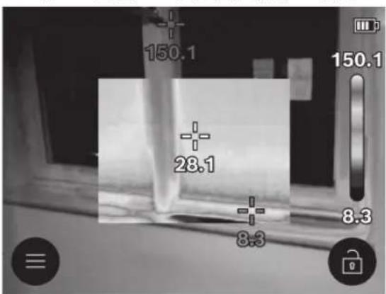
Vertical measurements from the front can be disrupted by the heat of the body. On a smooth surface, the outlines of your body may be displayed (reflected value), which do not correspond to the actual value of the measured surface (emitted value or actual surface value). Measuring through transparent objects (such as glass or clear plastics) is not possible at all. The more stable and better the measurement conditions, the more accurate and reliable the results. Not only strong temperature fluctuations in the ambient conditions are important, but also strong temperature fluctuations of the measured object can affect accuracy. Dust, high humidity, or air with dust particles can affect infrared temperature measurement.
Tips for better measurement accuracy: Reduce the factors causing errors between you and the measured surface.
Move closer to the measurement target to-
Measurement in the environment-
Ventilate the room, especially when the air is humid, and allow the room to cool down until it returns to normal temperature.
Marking the measurement spot
Do not look into the laser beam, even from a distance.
Do not point the laser beam at persons or animals.
The measuring tool is equipped with a laser for marking the measurement spot. Press and hold the laser button (13). The laser symbol (f) is shown in the status bar, and a red circle appears around the plus indicator (m). The laser and the plus indicator are precisely aligned at a distance of 1 m. When you release the laser button (13), the laser switches off.
Arranging temperature values according to the scale
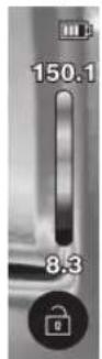
On the right side of the display, the scale (i) is shown. The extreme values at the top and bottom are based on the maximum temperature (j) or minimum temperature (h) recorded in the thermal image. For 99.99% of all pixels, the values are considered. The assignment of a color to a temperature value in the image is done with equal distribution (linear). With the help of the different color spectrum, the approximate temperature between these two values can be determined. The temperature that lies exactly between the maximum and minimum values can be assigned, for example, to the middle color range of the scale. To correctly determine the temperature range, align the tool so that the plus indicator is aligned with the temperature indicator (n).
They are not affected by this. The display changes. To change the color palette, call up the side bar and scroll through the "Color palette" menu until the end. Confirm your selection by pressing the multi-function button (17) in the center.
Grading scale

The color distribution in the thermal image is adjusted automatically, but it can also be set by pressing the multi-function button (17) on the right side and then in the center. This allows comparison of thermal images taken under different temperature conditions (for example, when checking several rooms for thermal bridges) or the masking of a very cold or hot object in the thermal image that would otherwise distort it (for example, a radiator as a hot object when searching for thermal bridges).
To return the grading to automatic mode, call up the right side bar and press the multi-function button (17) in the center. The temperature now behaves dynamically again and is adjusted according to the measured minimum and maximum values.
Main menu
Call up the left side bar (see "Navigating in menus", page 353). To reach the main menu, press the multi-function button (17) in the center.
Delete saved images individually or all at once.
The emission levels for some of the most common materials are available. To make searching easier, the values have been compiled in the catalog for emission levels. In the menu item, first select the appropriate group and material. If you know the exact emission level of the object you are measuring, you can also enter it as a numerical value in the menu item.
Adjusting this section improves the measurement result, especially for materials with low emission ( = high reflection). In many cases (especially indoors), the reflected temperature corresponds to the ambient temperature. If objects with very high temperature differences are near highly reflective objects, they may affect the measurement; you should adjust this value. For this purpose, press the multi-function button (17) on the left or right side.
For better orientation (allocation of the displayed thermal image), an additional real image can be activated in the same temperature ranges.
Note: The alignment of the real image and the thermal image is fixed at a distance of 1 m. If the distance to the object being measured changes, the thermal image and the real image may not coincide. This deviation can be compensated with special lenses. Information about lenses and their compatibility can be found on the product page of the measuring tool or at the following website: www.bosch-professional.com/thermal
The measuring tool offers the following options:
Only the thermal image is displayed.

Infrared image
Transparent
The thermal image shown as transparent is placed over the real image. This allows objects to be better identified. To activate/deactivate this setting, call up the sidebar Visual> on the left and scroll to the menu item /<Visual image off. Confirm your selection by pressing the multi-function button (17) in the center.

Picture-in-picture
To activate Picture-in-Picture, press the multi-function button (17) in the center to confirm.
- <Refl
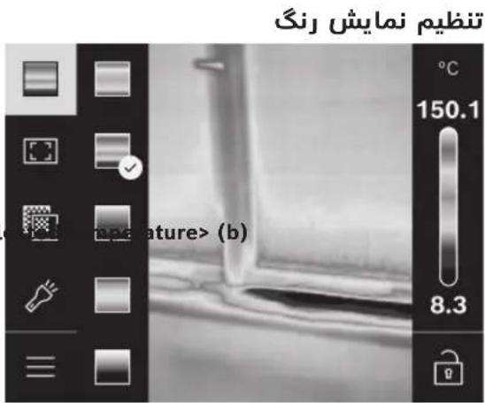
Depending on the measurement task, different color palettes can make thermal image analysis easier and show objects or relevant items more clearly on the display. Therefore, the measured temperatures
356 | English
In this submenu, you can not only set the time and date, but also change their format.
In this menu item, you can select the language used on the display.
In this menu item, you can reset the measuring tool to factory settings and permanently delete all data. This may take several minutes under certain conditions. Press the multi-function button (17) on the right to delete all files, or press the multi-function button (17) on the left to cancel the process.
In this menu item, you can call up information about the measuring tool. There you will find the serial number of the measuring tool and the version of the installed software. You can also find more information about the measuring tool and software updates there. To exit the selected menu and return to the standard display on the screen, you can press the measurement button (6).
Updating the measuring tool software
If necessary, you can update the measuring tool software via the USB Type-C® interface. You can find the relevant information on the following website: www.bosch-professional.com/thermal-update
Documentation of measurement results
Saving the measurement result
Immediately after switching on, the measuring tool starts working and continues until it is switched off. To save an image, point the tool at the object to be measured and press the measuring button (6). The image is saved in the internal memory of the measuring tool. The measurement is frozen and displayed on the screen. This allows you to look at the image carefully and make further settings (for example, color palette). If you do not want to save the frozen image, press the measuring button (6) again to restart the measurement. If you want to save the image in the internal memory of the measuring tool, press the multifunction button (17) in the center.
Retrieving saved images
To retrieve saved thermal images, proceed as follows:
Press again in the center. Now the image
-
To ensure high accuracy over the entire measuring range, measurements are taken in 2 temperature ranges
- are carried out. In the measuring mode, the measuring tool automatically selects the appropriate temperature range based on the temperature distribution in the thermal image
- selects. With this, the evaluator can see how many of the measured values are above a certain temperature threshold. If very small but hot objects are to be measured, the low temperature range may be unsuitable for high temperatures. This can be recognized by the symbol in the temperature indicator. In this case, at 100 °C ... 450 °C > engineering 6-20 °C ... 100 °C>
- If the set temperature matches, this setting can be recognized by an arrow pointing up or down on the scale.
This point is displayed in the center of the thermal image and shows you the measured temperature value.
The hottest point (= measuring pixel) is marked with a red plus indicator in the thermal image. This facilitates the search for hot spots (for example, loose connection clamps in a switchboard).
The coldest point (= measuring pixel) is marked with a blue plus indicator in the thermal image. This facilitates the search for critical spots (for example, unsealed joints in a window).
The average temperature (c) is displayed at the top left of the thermal image (the average temperature of all measured values in the thermal image). This can make it easier for you to determine the reflected temperature.
In this menu item, you can adjust the brightness of the display.
In this menu item, you can select the duration for the automatic switch-off of the work light if no button is pressed.
In this menu item, you can select the time after which, once it has elapsed and if no button is pressed, the measuring tool will automatically switch off (17). You can also deactivate the automatic switch-off by selecting the corresponding setting.
-<Temperature range
-
- / :Center
- / :Hot spot
- / :Cold spot
- / :Temperature
- / :Average
-
-
- <LED switch off after
- <Tool switch off after
357 | Check
Data transfer
USB data transfer via the interface
16. Open the USB Type-C® (11) cover. 17. Connect the socket (12) of the measuring tool to the supplied USB Type-C® (14) cable and then to your personal computer.
18. Switch on the measuring tool using the on/off button.
Open the macro file on your computer and select the drive 120450 GTC_450. The saved files can be copied from the internal memory of the measuring tool and transferred to your computer or deleted. When the desired process is complete, safely disconnect the drive from the computer and then switch off the measuring tool again using the on/off button (18). Note: Always eject the drive before disconnecting it from the system, otherwise the internal memory of the measuring tool may be damaged.
Disconnect the USB Type-C® cable and close the cover.
Always keep the USB interface cover closed to prevent dust or particles from entering the device.
Note: Connect the measuring tool to the computer via USB. If connected to other devices, the measuring tool may be damaged. Note: The USB Type-C® interface is used for data transfer. Batteries and rechargeable batteries are not charged via this interface.
Processing thermal images
You can edit the saved thermal images with Bosch software programs. Information about the programs and their compatibility can be found on the product page of the measuring tool or at the following website: www.bosch-professional.com/thermal
A preview of the last saved image appears on the display.
Call up the menu.
- Select the saved image in the item
Saved thermal images-
Press the multi-function button (17) to the right or left.
In addition to the thermal image, a visual image is also saved. To view it, press the multi-function button (17) up or down.
After 5 seconds, the measuring tool switches to full-screen view. In full-screen view, the title bar disappears so you can see all the details of the thermal image.
By pressing the multifunction button (17) up and down, you can change the view.
To delete individual or all saved images, press the multifunction button (17) in the center. A submenu opens.
Confirm your selection in the center with the multifunction button (17). You can choose between the options using the multifunction button (17) and confirm your selection in the center.
You can view the emission coefficient and the reflected temperature.
Parts of the image files remain in memory and can be restored. For final deletion, select the corresponding option in the main menu.
Errors – causes and solutions
If an error occurs, the measuring tool restarts and can be used again immediately. Otherwise, the overview of persistent error messages will help you.
| خُطَا | ||
| ابزار اندازه گیری روشن نمی شود. | ||
| باتری قابل شارژ/باتی های معمولی خالی است م permولی |  | |
| باتری قابل شارژ یا باتری های م permولی را تعويض کنید. مشکل در باتری های قابل شارژ/باتری های م permولی |  | |
| بگذارید باتری قابل شارژ خنک شود یا باتری قابل شارژ یا باتری های م permولی را تعويض کنید. باتری قابل شارژ/باتری های م permولی خنید گرم یا خیلی سرد است | | |
Allow the measuring tool to cool down.
The measuring tool is too hot or too cold.
Check whether the measuring tool is connected to another computer. If not, send the measuring tool to an authorized Bosch service center. Note: Always use the supplied USB cable.
The USB cable or USB connection is damaged.
The measuring tool cannot be connected to the computer.
The button battery is empty.
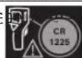
Replace the button battery.
Replace the button battery (see figure C) (17) on page 359. Confirm by pressing the multi-function button "OK". In the center, change the setting to "a" (17).
| مeditر مباني (م) | مeditر مباني (م) | مeditر مباني (م) |
| 0,301,14 | ||
| 0,552,08 | ||
| 1,003,79 | ||
| 2,007,58 | ||
| 5,0018,9 |
Explanation of concepts
For more information, visit
www.bosch-professional.com/thermal
to view.
Infrared heat radiation
Infrared heat radiation is a type of
electromagnetic radiation that is emitted by any object above -273.15°C
The emissivity of the object depends on the surface.
The degree of surface
Care and service
Care, repair and cleaning of the device
The measuring tool should only be stored and transported in a case, such as the original packaging. Always keep the measuring tool clean. Contamination on the infrared sensor (5) can affect the accuracy of the measurement. When cleaning, do not allow liquids to enter the measuring tool.
Do not attempt to remove dirt from the infrared sensor (5), the camera (3), the work light (4), or the laser outlet (2) with sharp objects. Do not wipe the infrared sensor or the camera (risk of scratches). In particular, regularly clean the surfaces around the laser outlet, and be careful to use a lint-free cloth. If you wish to have your measuring tool recalibrated, please contact an authorized Bosch service center.
If repair is needed, send the measuring tool in its original packaging. There are no user-serviceable parts inside the measuring tool. Opening the housing may damage the measuring tool.
The emissivity of an object depends on the material and surface structure. It indicates how much infrared heat radiation the object emits compared to an ideal black body (emissivity = 1). The emissivity value is between 0 and 1.
Thermal bridge
A thermal bridge is a location in the external wall of a building where the structure leads to increased heat loss in that area. Thermal bridges can increase the risk of mold formation.
Reflected temperature
Reflected temperature refers to infrared radiation that is not emitted by the object itself. Depending on the surface and material, ambient radiation is reflected by the object being measured, which can cause errors in the actual temperature reading.
Object distance
The distance between the measured object and the measuring tool affects the size of the area determined by each pixel. As the distance to the object increases, you can measure larger objects.
359 | Service
Rechargeable batteries / pen batteries: Lithium-ion:
Please observe the notes in the section (see "Battery", page 359).
Replacing the button battery (see figure C)
Open the cover (11).
Press and hold the latch (10) of the button battery holder and pull it out. Pull the button battery holder (9) out of the measuring tool. Replace the button battery. After inserting the button battery holder, press the latch (10) back in.
Service and customer advice
The after-sales service department will answer your questions about repairs, service, and also spare parts and accessories. Images and information about spare parts and accessories can be found on the website mentioned below: www.bosch-pt.com Your Bosch advisory team will support you with any questions about our products and accessories. For any questions or orders for spare parts and accessories, please always provide the ten-digit article number on the type plate of the power tool.
Iran
Robert Bosch Iran - Bosch Pars Trading Company Vanak Square, Shahid Khodami Street, Aftab Street Madiran Building, No. 3, Third Floor. 1994834571 Tehran 1994834571 +9821 42039000 Phone:
You can find other service information here:
www.bosch-pt.com/serviceaddresses
Transport
Lithium-ion batteries are subject to the Dangerous Goods Legislation. The user can transport the batteries by road without further requirements. When shipping by third parties (e.g. air transport or forwarding agency), special requirements on packaging and labelling must be complied with. For preparation of the item being shipped, consulting an expert for hazardous material is required. Only dispatch rechargeable batteries if the housing is not damaged. Tape open contacts and pack up the battery so that it cannot move around in the packaging. Please also observe possibly more detailed national regulations.
Disposal
Measuring tools, batteries, accessories, and packaging should be sorted for environmental-friendly recycling. Do not dispose of measuring tools and rechargeable batteries / batteries in household waste!




- DEUTSCH
- SICHERHEITSHINWEISE
- TRANSPORT
- ENGLISH
- WARNING
- PRODUCT DESCRIPTION AND SPECIFICATIONS
- INTENDED USE
- PRODUCT FEATURES
- DISPLAY ELEMENTS
- THERMAL IMAGING CAMERA GTC 12V
- MEASURING TOOL POWER SUPPLY
- OPERATION WITH RECHARGEABLE BATTERY (SEE FIGURE A)
- OPERATION WITH NON-RECHARGEABLE BATTERIES (SEE FIGURE B)
- RECOMMENDATIONS FOR OPTIMAL HANDLING OF THE BATTERY
- OPERATION
- STARTING OPERATION
- SWITCHING ON FOR THE FIRST TIME
- SWITCHING ON AND OFF
- NAVIGATING IN THE VARIOUS MENUS
- MEASUREMENT PREPARATIONS
- SETTING THE EMISSIVITY FOR SURFACE TEMPERATURE MEASUREMENTS
- HIGHLY REFLECTIVE OR SHINY SURFACES (E.G. SHINY TILES OR POLISHED METALS) MAY SIGNIFICANTLY DISTORT OR IMPAIR THE RESULTS SHOWN. IF NECESSARY, MASK THE MEASURING SURFACE WITH A DARK, MATT ADHESIVE TAPE THAT CONDUCTS HEAT WELL. ALLOW THE TAPE TO BRIEFLY REACH THE CORRECT TEMPERATURE ON THE SURFACE. MAKE SURE THAT A FAVOURABLE MEASURING ANGLE IS USED ON REFLECTIVE SURFACES IN ORDER TO ENSURE THAT THE THERMAL RADIATION REFLECTED BY OTHER OBJECTS DOES NOT DISTORT THE RESULT. FOR EXAMPLE, THE REFLECTION OF YOUR OWN EMITTED BODY HEAT MAY INTERFERE WITH THE MEASUREMENT WHEN MEASURING HEAD-ON FROM A PERPENDICULAR POSITION. ON A LEVEL SURFACE, THE OUTLINE AND TEMPERATURE OF YOUR BODY COULD THEREFORE BE DISPLAYED (REFLECTED VALUE), AND THESE VALUES DO NOT CORRESPOND TO THE ACTUAL TEMPERATURE OF THE MEASURED SURFACE (EMITTED VALUE OR REAL VALUE OF THE SURFACE)
- MARKING THE MEASURING POINT
- ASSIGNING TEMPERATURES ON THE BASIS OF THE SCALE
- FUNCTIONS
- ILLUMINATING THE OBJECT BEING MEASURED
- COMPLETE INFRARED IMAGE
- TRANSPARENCY
- IMAGE IN IMAGE
- FIXING THE SCALE
- MAIN MENU
- (A)
- (B)
- UPDATING THE MEASURING TOOL SOFTWARE
- DOCUMENTING MEASUREMENTS
- SAVING MEASUREMENTS
- CALLING UP SAVED IMAGES
- DELETING SAVED IMAGES
- DATA TRANSFER
- DATA TRANSFER VIA USB PORT
- POST-EDITING THE THERMAL IMAGES
- ERRORS – CAUSES AND CORRECTIVE MEASURES
- GLOSSARY OF TERMS
- INFRARED THERMAL RADIATION
- EMISSIVITY
- THERMAL BRIDGE
- REFLECTED TEMPERATURE/REFLECTIVITY OF AN OBJECT
- DISTANCE FROM THE OBJECT
- MAINTENANCE AND SERVICE
- MAINTENANCE AND CLEANING
- CHANGING THE COIN CELL (SEE FIGURE C)
- AFTER-SALES SERVICE AND APPLICATION SERVICE
- GREAT BRITAIN
- YOU CAN FIND FURTHER SERVICE ADDRESSES AT
- DISPOSAL
- ONLY FOR EU COUNTRIES
- ONLY FOR UNITED KINGDOM
- BATTERY PACKS/BATTERIES
- FRENCH
- SAFETY INSTRUCTIONS
- DESCRIPTION OF SERVICES AND PRODUCT
- COMPONENT PARTS
- DISPLAYS
- POWER SUPPLY FOR THE MEASURING DEVICE
- OPERATION WITH BATTERY (SEE FIGURE A)
- OPERATION WITH BATTERIES (SEE FIGURE B)
- THIS PURPOSE. IT IS NOT DESIGNED FOR USE WITH POWER TOOLS
- INDICATIONS FOR OPTIMAL BATTERY USE
- START-UP
- ON FIRST START-UP
- SWITCHING ON/OFF
- WHEN USING THE CAMERA, ENSURE THAT THE INFRARED SENSOR IS NOT BLOCKED OR COVERED
- NAVIGATING THE MENUS
- PREPARING THE MEASURING TOOL
- NOTES ON MEASUREMENT CONDITIONS
- MARKING THE MEASUREMENT POINT
- TEMPERATURE DISTRIBUTION ON THE TEMPERATURE SCALE
- ILLUMINATION OF THE OBJECT TO BE MEASURED
- FREEZING THE TEMPERATURE SCALE
- SOFTWARE UPDATE FOR THE MEASURING DEVICE
- DOCUMENTATION OF MEASUREMENT RESULTS
- STORING MEASUREMENT RESULTS
- DISPLAYING STORED IMAGES
- DELETING STORED IMAGES
- POST-EDITING OF THERMAL IMAGES
- FAULTS – CAUSES AND REMEDIES
- FAULT CAUSE REMEDY
- DEFINITIONS
- DISTANCE TO THE MEASUREMENT OBJECT
- MAINTENANCE AND AFTER-SALES SERVICE
- CLEANING AND MAINTENANCE
- REPLACING THE BUTTON BATTERY (SEE FIGURE C)
- AFTER-SALES SERVICE AND USER ADVICE
- FRANCE
- YOU WILL FIND OTHER SERVICE ADDRESSES AT
- WASTE DISPOSAL
- RECHARGEABLE BATTERIES/BATTERIES
- VALID ONLY FOR FRANCE
- SPANISH
- PRODUCT DESCRIPTION AND SERVICE
- REPRESENTED COMPONENTS
- INDICATING ELEMENTS
- POWER SUPPLY FOR THE MEASURING TOOL
- TIPS FOR OPTIMAL HANDLING OF THE RECHARGEABLE BATTERY
- ON FIRST CONNECTION
- PREPARATIONS FOR MEASUREMENT
- TEMPERATURE ASSIGNMENT ACCORDING TO THE SCALE
- ILLUMINATION OF THE MEASUREMENT OBJECT
- SOFTWARE UPDATE OF THE MEASURING TOOL
- VIEWING STORED IMAGES
- DATA TRANSFER VIA USB INTERFACE
- POST-PROCESSING OF THERMAL IMAGES
- FAULTS - CAUSES AND REMEDIES
- GLOSSARY
- INFRARED HEAT RADIATION
- DISTANCE TO THE OBJECT
- REPLACING THE BUTTON CELL BATTERY (SEE FIGURE C)
- SERVICE AND CUSTOMER SUPPORT
- SPAIN
- MEXICO
- BATTERIES
- LITHIUM-ION
- PORTUGUESE
- ILLUSTRATED COMPONENTS
- INDICATION ELEMENTS
- TECHNICAL DATA
- BATTERY OPERATION (SEE FIGURE A)
- BATTERY OPERATION WITH CONVENTIONAL BATTERIES (SEE FIGURE B)
- OPTIMAL HANDLING OF THE BATTERY
- ON FIRST USE
- NAVIGATING THE VARIOUS MENUS
- MEASUREMENT PREPARATION
- INDICATIONS ON MEASUREMENT CONDITIONS
- ASSIGNMENT OF TEMPERATURES BASED ON THE SCALE
- OVERLAY OF THERMAL AND REAL IMAGES
- SOFTWARE UPDATE FOR THE MEASURING TOOL
- SAVING MEASUREMENT RESULTS
- ACCESSING SAVED IMAGES
- ERRORS - CAUSES AND SOLUTIONS
- EXPLANATION OF TERMS
- OBJECT DISTANCE
- AFTER-SALES SERVICE AND ADVICE
- AT: WWW.BOSCH-PT.COM
- BRAZIL
- PORTUGAL
- OTHER SERVICE ADDRESSES CAN BE FOUND AT
- ITALIAN
- PRODUCT DESCRIPTION AND SERVICES PROVIDED
- NOTES FOR OPTIMAL BATTERY USE
- USE
- INITIAL STARTUP
- SETTING THE EMISSION LEVEL FOR SURFACE TEMPERATURE MEASUREMENTS
- TEMPERATURE MEASUREMENTS CAN ONLY BE PERFORMED CORRECTLY IF THE SET EMISSIVITY MATCHES THAT OF THE OBJECT
- TEMPERATURE ASSIGNMENT BASED ON THE ROOM
- ILLUMINATION OF THE MEASURING OBJECT
- OVERLAY OF THERMAL AND REAL IMAGE
- PICTURE-IN-PICTURE
- FIXED SCALE
- RECALLING STORED IMAGES
- PROCESSING THERMAL IMAGES
- ERRORS – CAUSES AND REMEDIES
- EXPLANATION OF DEFINITIONS
- REFLECTED TEMPERATURE / REFLECTIVITY OF AN OBJECT
- AFTER-SALES SERVICE AND TECHNICAL ADVICE
- ITALY
- FURTHER SERVICE ADDRESSES ARE LISTED BELOW
- BATTERIES/RECHARGEABLE BATTERIES
- FOR LITHIUM-ION BATTERIES
- DUTCH
- DESCRIPTION OF PRODUCT AND OPERATION
- INDICATORS
- INITIAL OPERATION
- WHEN SWITCHING ON FOR THE FIRST TIME
- NOTES ON MEASURING CONDITIONS
- TEMPERATURE CLASSIFICATION ACCORDING TO THE SCALE
- ILLUMINATING THE MEASURING OBJECT
- INFRARED IMAGE
- LOCK THE SCALE
- UPDATE MEASURING TOOL SOFTWARE
- DOCUMENTING MEASUREMENT RESULTS
- RETRIEVING SAVED IMAGES
- ERRORS - CAUSES AND REMEDIES
- REPLACING THE BUTTON CELL (SEE FIGURE C)
- CUSTOMER SERVICE AND USAGE ADVICE
- NETHERLANDS
- FOR MORE SERVICE ADDRESSES, SEE
- LI-ION
- DANISH
- PRODUCT DESCRIPTION AND PERFORMANCE
- OPERATION WITH BATTERY PACK (SEE FIGURE A)
- SET THE EMISSIVITY FOR SURFACE TEMPERATURE MEASUREMENTS
- REFERENCES REGARDING MEASURING CONDITIONS
- MARKING THE MEASURING SPOT
- INTERPRETING THE TEMPERATURES USING THE SCALE
- LOCKING THE SCALE
- OPENING SAVED IMAGES
- ERRORS – CAUSES AND CORRECTIVE ACTION
- ERROR CAUSE CORRECTIVE ACTION
- THERMAL BRIDGES
- CUSTOMER SERVICE AND APPLICATION ADVICE
- FURTHER SERVICE ADDRESSES CAN BE FOUND AT
- SWEDISH
- APPLIES ONLY TO EU COUNTRIES
- RECHARGEABLE BATTERIES
- PRODUCT AND PERFORMANCE DESCRIPTION
- DEPICTED COMPONENTS
- POWER SUPPLY FOR MEASURING TOOL
- INSTRUCTIONS FOR CORRECT HANDLING OF THE BATTERY MODULE
- AT FIRST SWITCH-ON
- INSTRUCTIONS FOR MEASUREMENT CONDITIONS
- TEMPERATURE SCALE DIVISION
- FIX THE SCALE
- UPDATING MEASURING INSTRUMENT SOFTWARE
- DELETE SAVED IMAGES
- ERROR CAUSE CORRECTIVE MEASURE
- HEAT LEAK
- REFLECTED TEMPERATURE OF AN OBJECT
- WWW.BOSCH-PT.COM
- NORWEGIAN
- PRODUCT DESCRIPTION AND PERFORMANCE SPECIFICATIONS
- OPERATION WITH DISPOSABLE BATTERIES (SEE FIGURE B)
- RULES FOR OPTIMAL USE OF RECHARGEABLE BATTERIES
- PREPARATION FOR MEASUREMENT
- SETTING THE EMISSION FACTOR FOR SURFACE TEMPERATURE MEASUREMENTS
- CORRECT TEMPERATURE MEASUREMENT REQUIRES THAT THE SET EMISSION FACTOR AND THE OBJECT'S EMISSION FACTOR MATCH
- INFORMATION ON MEASUREMENT CONDITIONS
- NEVER POINT THE LASER BEAM AT PEOPLE OR ANIMALS, AND DO NOT LOOK INTO THE LASER BEAM YOURSELF, EVEN FROM A DISTANCE
- ASSIGNING TEMPERATURES USING THE SCALE
- UPDATING THE MEASURING TOOL'S SOFTWARE
- LARGE MEASUREMENT RESULTS
- ERRORS - CAUSE AND REMEDY
- IR THERMAL RADIATION
- REFLECTED TEMPERATURE / AN OBJECT'S REFLECTIVE PROPERTIES
- SERVICE AND MAINTENANCE
- AFTER-SALES SERVICE AND CUSTOMER ADVICE
- FINNISH
- PRODUCT DESCRIPTION AND FEATURES
- PARTS DESCRIBED
- TIPS FOR OPTIMAL HANDLING OF THE BATTERY
- PREPARING THE MEASUREMENT
- CORRECT RESULTS IN TEMPERATURE MEASUREMENT ARE ONLY OBTAINED WHEN THE EMISSIVITY SET ON THE DEVICE AND THE EMISSIVITY OF THE OBJECT MATCH EACH OTHER
- ASSIGNING TEMPERATURES TO THE SCALE
- VISIBLE
- IN IMAGE
- VIEWING SAVED IMAGES
- FAULTS - CAUSES AND CORRECTIVE MEASURES
- REFLECTED TEMPERATURE / REFLECTIVITY OF THE OBJECT
- CARE AND MAINTENANCE
- FINLAND
- YOU CAN FIND MORE SERVICE ADDRESSES UNDER
- APPLIES TO EU COUNTRIES ONLY
- TIPS FOR OPTIMAL BATTERY HANDLING
- DURING INITIAL START-UP
- SETTING THE EMISSIVITY FOR MEASURING SURFACE TEMPERATURE
- GO TO IMAGE
- FREEZING THE SCALE
- DATA TRANSFER VIA USB INTERFACE PORT
- INTERPRETATION OF DEFINITIONS
- CHANGING THE BUTTON BATTERY (SEE FIGURE P)
- GREECE
- FURTHER SERVICE ADDRESSES CAN BE FOUND HERE
- FOR EU COUNTRIES ONLY
- TURKISH
- HAND THEM OVER TO THE NEXT USER OF THE MEASURING TOOL
- DISPLAYED COMPONENTS
- MEASURING DEVICE POWER SUPPLY
- WORKING WITH THE BATTERY (SEE FIGURE A)
- WORKING WITH BATTERIES (SEE FIGURE B)
- INSTRUCTIONS FOR OPTIMAL BATTERY USE
- PREPARATION FOR MEASURING
- SETTING THE EMISSION DEGREE FOR SURFACE TEMPERATURE MEASUREMENTS
- DETERMINING TEMPERATURES USING THE SCALE
- ILLUMINATION OF THE MEASURED OBJECT
- ERRORS – CAUSES AND SOLUTIONS
- ERROR CAUSE SOLUTION
- CONCEPT EXPLANATIONS
- CUSTOMER SERVICE AND APPLICATION CONSULTING
- TURKEY
- POLISH
- PRODUCT DESCRIPTION AND INTENDED USE
- GRAPHICALLY DEPICTED COMPONENTS
- INDICATIONS
- THERMAL CAMERA GTC 12V
- INSTRUCTIONS FOR PROPER HANDLING OF THE RECHARGEABLE BATTERY
- SETTING THE EMISSIVITY BEFORE MEASURING SURFACE TEMPERATURE
- CORRECT TEMPERATURE MEASUREMENT IS ONLY POSSIBLE IF THE SET EMISSIVITY AND THE EMISSIVITY OF THE OBJECT ARE IDENTICAL
- TIPS ON MEASUREMENT CONDITIONS
- MARKING THE MEASUREMENT SPOT
- INTERPRETING TEMPERATURES USING THE SCALE
- TRANSPARENT IMAGE
- DATA TRANSMISSION
- DATA TRANSMISSION VIA USB CONNECTION
- TERMINOLOGY
- INFRARED RADIATION
- REPLACING THE ROUND BATTERY (SEE FIGURE C)
- CZECH
- NOTE FOR OPTIMAL HANDLING OF THE BATTERY
- AT FIRST START-UP
- SETTING THE EMISSIVITY FOR SURFACE TEMPERATURE MEASUREMENT
- CORRECT TEMPERATURE MEASUREMENT IS ONLY POSSIBLE IF THE SET EMISSIVITY MATCHES THE OBJECT
- ASSIGNING TEMPERATURES ACCORDING TO THE SCALE
- SOFTWARE UPDATE OF THE MEASURING INSTRUMENT
- RECALLING SAVED IMAGES
- REFLECTED TEMPERATURE/EMISSIVITY OF THE OBJECT
- CZECH REPUBLIC
- SLOVAK
- POWER SUPPLY FOR THE MEASURING INSTRUMENT
- INSTRUCTIONS FOR OPTIMAL HANDLING OF THE RECHARGEABLE BATTERY
- NAVIGATION IN THE INDIVIDUAL MENUS
- PREPARING FOR MEASUREMENT
- SETTING THE EMISSIVITY LEVEL FOR SURFACE TEMPERATURE MEASUREMENT
- INSTRUCTIONS ON MEASUREMENT CONDITIONS
- SETTING A FIXED SCALE
- SAVING MEASUREMENT RESULTS TO MEMORY
- ERROR CAUSE REMEDY
- REFLECTED TEMPERATURE/REFLECTIVITY OF THE OBJECT
- SLOVAKIA
- MEASURING INSTRUMENTS, BATTERIES, ACCESSORIES, AND PACKAGING SHOULD BE RECYCLED IN AN ENVIRONMENTALLY FRIENDLY MANNER
- HUNGARIAN
- SAFETY INFORMATION
- COMPONENTS SHOWN IN THE FIGURES
- INFORMATION ON OPTIMAL HANDLING OF THE BATTERY
- MEASUREMENT CONDITIONS
- DO NOT POINT THE LIGHT BEAM AT PEOPLE OR ANIMALS AND DO NOT LOOK DIRECTLY INTO THE LASER BEAM YOURSELF – EVEN FROM A GREATER DISTANCE
- ILLUMINATING THE MEASURED OBJECT
- TRANSPARENT DISPLAY
- DATA TRANSFER VIA THE USB INTERFACE
- REFLECTED TEMPERATURE / REFLECTIVE ABILITY OF AN OBJECT
- REPLACING THE BATTERY (SEE FIGURE C)
- AFTER-SALES SERVICE AND APPLICATION ADVICE
- HUNGARY
- ONLY FOR EU MEMBER STATES
- RUSSIAN
- FOR COUNTRIES OF THE EURASIAN ECONOMIC UNION ONLY
- (CUSTOMS UNION)
- PRODUCT SERVICE LIFE
- LIST OF CRITICAL FAILURES AND ERRONEOUS ACTIONS OF PERSONNEL OR USER
- CRITERIA FOR LIMIT STATES
- TYPE AND FREQUENCY OF MAINTENANCE
- STORAGE
- TRANSPORTATION
- PRODUCT DESCRIPTION AND SERVICES
- OPERATING WITH THE BATTERY (SEE FIGURE A)
- WORKING WITH THE TOOL
- ON FIRST USE OF THE MEASURING TOOL OR AFTER RESETTING IT TO FACTORY SETTINGS, SOME BASIC SETTINGS NEED TO BE CONFIGURED. SELECT THE DESIRED VALUES BY PRESSING THE MULTI-FUNCTION BUTTON (17) DOWN, UP, LEFT, OR RIGHT. PRESS THE MULTI-FUNCTION BUTTON (17) IN THE MIDDLE TO CONFIRM YOUR SELECTION. ONCE YOU CONFIRM THE SELECTION, THE NEXT SETTING WILL APPEAR ON THE DISPLAY. THE STATUS BAR AT THE TOP SHOWS THE TOTAL NUMBER AND THE NUMBER OF REMAINING SETTINGS
- ON/OFF
- CORRECT TEMPERATURE MEASUREMENT IS ONLY POSSIBLE WHEN THE SET EMISSIVITY AND THE EMISSIVITY OF THE OBJECT MATCH
- DO NOT POINT THE LASER BEAM AT PEOPLE OR ANIMALS, AND DO NOT LOOK INTO THE LASER BEAM YOURSELF, EVEN FROM A GREAT DISTANCE
- ORDER OF TEMPERATURE VALUES ON THE SCALE
- SCALE LOCKING
- MALFUNCTION – CAUSES AND CORRECTIVE ACTION
- REFLECTED TEMPERATURE/REFLECTIVITY OF OBJECTS
- SERVICE AND APPLICATION CONSULTING
- FOR THE REGION: RUSSIA, BELARUS, KAZAKHSTAN
- RUSSIA
- THERMAL IMAGER GTC 12V
- OPERATION WITH THE BATTERY (SEE FIGURE A)
- DURING FIRST START-UP
- NAVIGATION IN THE VARIOUS MENUS
- SETTING THE EMISSION FACTOR FOR SURFACE TEMPERATURE MEASUREMENT
- OVERLAY
- USER-DEFINED
- (M)
- (N)
- (I)
- (S)
- UKRAINIAN
- ADDITIONAL PROCESSING OF THERMAL IMAGES
- MALFUNCTIONS – CAUSES AND REMEDIES
- REPLACING THE MINIATURE BATTERY (SEE FIGURE C)
- UKRAINE
- FURTHER SERVICE ADDRESSES ARE LISTED AT
- VALID IN THE TERRITORIES OF THE MEMBER STATES OF THE EURASIAN ECONOMIC UNION (CUSTOMS UNION)
- LIST OF ERRORS AND FAILURE CAUSES BY PERSONNEL OR USER
- SIGNS OF LIMIT STATE
- PRODUCT AND POWER DESCRIPTION
- OPERATION WITH BATTERY
- (SEE FIGURE A)
- OPERATION WITH BATTERIES
- (SEE FIGURE B)
- NAVIGATING THROUGH THE VARIOUS MENUS
- SETTING THE EMISSION DEGREE FOR SURFACE TEMPERATURE MEASUREMENT
- CORRECT TEMPERATURE MEASUREMENTS ARE ONLY POSSIBLE WHEN THE SET EMISSION LEVEL MATCHES THE EMISSION LEVEL OF THE OBJECT
- MENU (SEE "MAIN MENU", PAGE 223)
- INSTRUCTIONS ON MEASURING CONDITIONS
- DO NOT POINT THE LASER BEAM AT PEOPLE OR ANIMALS, AND DO NOT LOOK INTO THE LASER BEAM YOURSELF, EVEN FROM A DISTANCE
- ASSIGNING TEMPERATURES ON THE SCALE
- KAZAKH
- TRANSFERRING DATA VIA USB INTERFACE
- ADDITIONAL PROCESSING OF THERMOGRAMS
- MALFUNCTIONS – CAUSES AND SOLUTIONS
- TERMINOLOGY EXPLANATIONS
- DEGREE OF EMISSION
- REFLECTED TEMPERATURE / OBJECT'S REFLECTIVITY
- SERVICE AND CLEANING
- AFTER-SALES SERVICE AND USAGE ADVICE
- KAZAKHSTAN
- YOU CAN FIND THE ADDRESSES OF SERVICE CENTERS HERE
- RECHARGEABLE BATTERIES/ BATTERIES
- BATTERY VOLTAGE
- TEMPERATURE RANGE (SEE FIGURE A)
- GEORGIAN
- INDIAN
- NOTES ON OPERATING CONDITIONS
- OPERATING INSTRUCTIONS
- RULE FOR PLACING TEMPERATURE VALUES
- UPDATING THE TOOL'S SOFTWARE
- POWER SUPPLY
- BONG
- SLUBHYWN 0Y03YDSYNGS/MONGY0N S6Y33N
- உெடுக்கு மேரம் மாற்றீதை
- FOR SERVICE AND REPAIR, PLEASE CONTACT THE FOLLOWING ADDRESS
- ROMANIAN
- NOTES ON OPTIMAL HANDLING OF THE RECHARGEABLE BATTERY
- MAKE SURE THAT THE INFRARED SENSOR IS NOT BLOCKED OR COVERED DURING WORK
- ASSIGNING TEMPERATURES BASED ON THE SCALE
- ILLUMINATING THE OBJECT TO BE MEASURED
- OVERLAYING THE THERMAL IMAGE WITH THE REAL IMAGE
- FURTHER PROCESSING OF THERMAL IMAGES
- DISTANCE FROM OBJECT
- REPLACING THE ROUND BATTERY (SEE IMAGE C)
- ROMANIA
- YOU CAN FIND OTHER SERVICE ADDRESSES AT
- BATTERIES/ACCUMULATORS
- PRODUCT DESCRIPTION AND OPERATION
- DISPLAYED ELEMENTS
- WORKING WITH THE RECHARGEABLE BATTERY (SEE FIGURE A)
- WORK
- NAVIGATE IN THE VARIOUS MENUS
- SETTING THE EMISSION COEFFICIENT FOR SURFACE TEMPERATURE MEASUREMENTS
- NOTES ON AMBIENT CONDITIONS DURING MEASUREMENT
- DO NOT POINT THE LASER BEAM AT PEOPLE OR ANIMALS; DO NOT LOOK INTO THE LASER BEAM, EVEN FROM A DISTANCE
- SETTING TEMPERATURES BASED ON THE SCALE
- SETTING THIS PARAMETER IMPROVES THE MEASUREMENT RESULT, ESPECIALLY FOR MATERIALS WITH LOW EMISSIVITY (= HIGH REFLECTIVITY). IN SOME SITUATIONS (ESPECIALLY INDOORS), THE REFLECTED TEMPERATURE CORRESPONDS TO THE AMBIENT TEMPERATURE. IF THERE ARE OBJECTS WITH SIGNIFICANTLY DIFFERENT TEMPERATURES NEAR HIGHLY REFLECTIVE OBJECTS THAT COULD AFFECT THE MEASUREMENT, THIS VALUE SHOULD BE ADJUSTED. TO DO THIS, PRESS THE MULTIFUNCTION BUTTON (17) TO THE LEFT OR RIGHT
- UPDATING THE SOFTWARE OF THE MEASURING INSTRUMENT
- MACEDONIAN
- CUSTOMER SERVICE AND USAGE CONSULTATION
- BULGARIA
- ADDITIONAL SERVICE ADDRESSES CAN BE FOUND AT
- SAFETY NOTES
- ILLUSTRATION OF COMPONENTS
- NOTES FOR OPTIMAL USE OF THE BATTERIES
- NAVIGATING THROUGH THE MENUS
- SETTING THE EMISSION LEVEL WHEN MEASURING SURFACE TEMPERATURE
- MALFUNCTION – CAUSES AND ASSISTANCE
- REFLECTED TEMPERATURE/OBJECT REFLECTION
- SERVICE DEPARTMENT AND USAGE ADVICE
- NORTH MACEDONIA
- SERBIAN
- PRODUCT DESCRIPTION AND APPLICATIONS
- ON FIRST SWITCHING ON
- SETTING THE EMISSION LEVEL FOR SURFACE TEMPERATURE MEASUREMENT
- INSTRUCTIONS FOR STARTING MEASUREMENT
- DO NOT POINT THE LASER BEAM AT PEOPLE OR ANIMALS AND DO NOT LOOK INTO THE LASER BEAM, EVEN FROM A DISTANCE
- DETERMINING TEMPERATURES BASED ON THE SCALE
- ILLUMINATING THE MEASUREMENT OBJECT
- ERROR – CAUSES AND REMEDY
- INFRARED HEAT EMISSION
- SERVICE AND ADVICE ON USE
- ACCUMULATORS/BATTERIES
- SLOVENIAN
- SAFETY WARNINGS
- COMPONENTS ILLUSTRATED
- INSTRUCTIONS FOR OPTIMAL USE OF THE RECHARGEABLE BATTERY
- MENU NAVIGATION
- PREPARING A MEASUREMENT
- DETERMINING THE TEMPERATURE SCALE
- FREEZING THE MEASUREMENT SCALE
- UPDATING THE MEASURING DEVICE SOFTWARE
- RECORDING MEASUREMENT RESULTS
- ERRORS – CAUSES AND ASSISTANCE
- MAINTENANCE AND SERVICING
- OTHER SERVICE ADDRESSES ARE LISTED UNDER
- CROATIAN
- NOTES FOR OPTIMAL HANDLING OF THE RECHARGEABLE BATTERY
- FINAL PROCESSING OF THERMAL IMAGES
- INTERFERENCE - CAUSES AND ASSISTANCE
- INTERFERENCE CAUSE ASSISTANCE
- ESTONIAN
- PRODUCT DESCRIPTION AND INSTRUCTIONS FOR USE
- USING BATTERIES (SEE FIGURE B)
- INSTRUCTIONS FOR HANDLING THE RECHARGEABLE BATTERY
- MEASURING TOOL SOFTWARE UPDATE
- MAINTENANCE AND CARE
- REPUBLIC OF ESTONIA
- PRODUCT DESCRIPTION AND FUNCTIONS
- BATTERY OPERATION (SEE FIGURE B)
- PROPER HANDLING OF THE RECHARGEABLE BATTERY
- FIRST USE
- DO NOT POINT THE LASER BEAM AT OTHER PERSONS OR ANIMALS AND DO NOT LOOK INTO THE LASER BEAM EVEN FROM A GREAT DISTANCE
- TEMPERATURE DETERMINATION USING THE SCALE
- OVERLAYING THE THERMAL IMAGE AND THE REAL IMAGE
- IN THE IMAGE
- THERMAL IMAGE POST-PROCESSING
- REFLECTED TEMPERATURE/OBJECT REFLECTIVITY
- REPUBLIC OF LATVIA
- ADDITIONAL SERVICE ADDRESSES ARE LISTED HERE
- DISPOSAL OF USED PRODUCTS
- BATTERIES/BATTERY PACKS
- LITHUANIAN
- PRODUCT AND FEATURE DESCRIPTION
- DISPLAY SYMBOLS
- POWER SUPPLY TO THE MEASURING TOOL
- PREPARATION FOR USE
- WHEN CONNECTING FOR THE FIRST TIME
- DO NOT POINT THE LASER BEAM AT OTHER PERSONS OR ANIMALS AND DO NOT LOOK INTO THE LASER BEAM YOURSELF, EVEN FROM A DISTANCE
- YOU CAN PROCESS THE SAVED THERMAL IMAGES WITH THE SPECIAL BOSCH APP. INFORMATION ABOUT THE APPS AND THEIR COMPATIBILITY CAN BE FOUND ON THE PRODUCT PAGE OF THE MEASURING TOOL OR AT WWW.BOSCH-PROFESSIONAL.COM/THERMAL
- FAULTS – CAUSE AND REMEDY
- EXPLANATIONS OF TERMS
- REFLECTED TEMPERATURE / OBJECT REFLECTIVITY
- AFTER-SALES SERVICE AND CONSULTING SERVICE
- LITHUANIA
- YOU CAN FIND OTHER SERVICE ADDRESSES HERE
- NOT SUITABLE FOR OTHER TOOLS AND CAN CAUSE SEVERE DAMAGE
- (SEE FIGURE)
- WHEN STARTING FOR THE FIRST TIME
- BOSCH MEASURING TOOLS MUST NOT BE USED WITH ELECTRICAL TOOLS
- NOTES FOR WORKING WITH THE DEVICE
- PROTECT
- FROM DIRECT SUNLIGHT
- ARABIC
- ANIMALS AND DO NOT DIRECT YOUR GAZE AT THE LASER BEAM
- EVEN FROM A DISTANCE
- NAVIGATING THE DIFFERENT MENUS
- MEASUREMENT SETTINGS
- SETTING THE EMISSIVITY FOR TEMPERATURE MEASUREMENTS
- BRIGHTNESS
- THE SET EMISSIVITY AND THE OBJECT'S EMISSIVITY
- THE EMISSIVITY
- ← PARAMETERS
- SETTING THE SCALE
- EXTENDING THE MEASURING TOOL
- ERROR
- MEANING
- INTERPRETATION OF THE MEASUREMENT
- THERMAL RADIATION
- فارسی
- PERSIAN
- PRODUCT DESCRIPTION AND FUNCTION
- INTENDED USE OF THE DEVICE
- DEVICE PARTS IMAGES
- INSTRUCTIONS AND NOTES FOR OPTIMAL BATTERY USAGE
- PROTECT FROM DIRECT SUNLIGHT
- START-UP AND OPERATION
- MEASURE THE BATTERY VOLTAGE (SEE FIGURE B)
- ENSURE THAT THE SET EMISSIVITY MATCHES THE EMISSIVITY OF THE OBJECT
- NAVIGATION IN THE MENUS
- TURNING ON THE WORK LIGHT
- DO NOT POINT THE LASER BEAM AT PERSONS OR ANIMALS
- ARRANGING TEMPERATURE VALUES ACCORDING TO THE SCALE
- GRADING SCALE
- SAVING THE MEASUREMENT RESULT
- USB DATA TRANSFER VIA THE INTERFACE
- EXPLANATION OF CONCEPTS
- CARE AND SERVICE
- CARE, REPAIR AND CLEANING OF THE DEVICE
- REFLECTED TEMPERATURE
- RECHARGEABLE BATTERIES / PEN BATTERIES: LITHIUM-ION
- SERVICE AND CUSTOMER ADVICE
Brand : BOSCH
Model : GTC 12V-450-13 Professional
Category : Measuring equipment