
WEP 17-125 Quick - Sander METABO - Free user manual and instructions
Find the device manual for free WEP 17-125 Quick METABO in PDF.

| Product Type | Angle Grinder / Sander |
| Brand | Metabo |
| Model | WEP 17-125 Quick |
| Max. tool diameter | 125 mm |
| Spindle thread | M14 |
| Grinding spindle length | 22 mm |
| No-load speed | 11 000 rpm |
| Input power | 1700 W |
| Output power | 1100 W |
| Weight (without cable) | 2.4 kg |
| Power supply | 230 V ~ 50 Hz |
| Protection class | II |
| Quick clamping system | M-Quick (Quick clamping nut) |
| Safety | S-automatic safety clutch, restart protection |
| Additional handle | With vibration damping (optional) |
| Protective guard | Tool-free adjustable |
| Main functions | Grinding, sanding, brushing, cutting (with suitable accessories) |
| Sound pressure level (LpA) | 91 dB(A) (K=3 dB) |
| Sound power level (LWA) | 102 dB(A) (K=3 dB) |
| Vibration (surface grinding) | 6.0 m/s² (uncertainty K=1.5 m/s²) |
| Vibration (sanding with backing pad) | 4.0 m/s² (uncertainty K=1.5 m/s²) |
| Maintenance and cleaning | Regularly clean ventilation slots with dry air |
| Spare parts and repairability | Parts lists on www.metabo.com; repair by a specialist |
| General information | Complies with EU directives; use only original Metabo accessories |
Frequently Asked Questions - WEP 17-125 Quick METABO
User questions about WEP 17-125 Quick METABO
0 question about this device. Answer the ones you know or ask your own.
Ask a new question about this device
Download the instructions for your Sander in PDF format for free! Find your manual WEP 17-125 Quick - METABO and take your electronic device back in hand. On this page are published all the documents necessary for the use of your device. WEP 17-125 Quick by METABO.
USER MANUAL WEP 17-125 Quick METABO
natural_image
Three metal angle power tools (meltar, Inoxi, Xeroul) displayed side by side, no visible text or symbols on the tools themselves.WEV 17-150 Quick
WEV 17-125 Quick Inox
WEV 17-125 Quick
WEV 17-125 Quick RT
WEV 17-125 Quick Inox RT
WE 19-180 Quick RT

Original instructions
1. Declaration of Conformity
We, being solely responsible: Hereby declare that these angle grinders, identified by type and serial number *1), meet all relevant requirements of directives *2) and standards *3). technical documents for *4) - see Page 4.
2. Specified Use
The angle grinders, when fitted with original Metabo accessories, are suitable for grinding, sanding, abrasive cutting-off operations and wire brushing metal, concrete, stone and similar materials without the use of water.
WEV 17-125 Quick Inox, WEV 17-125 Quick Inox RT is additionally suited for light polishing work. We recommend using our angle polisher for demanding polishing work in continuous operation.
Machines with the designation WEV are particularly suited for working with wire brushes due to thumbwheel for speed selection.
The user bears sole responsibility for any damage caused by inappropriate use.
Generally accepted accident prevention regulations and the enclosed safety information must be observed.
3. General Safety Instructions

For your own protection and for the protection of your power tool, pay attention to all parts of the text that are marked with this symbol!

WARNING – Reading the operating instructions will reduce the risk of injury.

WARNING Read all safety warnings and instructions. Failure to follow all safety
warnings and instructions may result in electric shock, fire and/or serious injury.
Keep all safety instructions and information for future reference.
Pass on your power tool only together with these documents.
4. Special Safety Instructions
4.1 Safety Warnings Common for Grinding, Sanding, Wire Brushing or Abrasive Cutting-Off Operations:
Use
a) This power tool is intended to function as a grinder, sander, wire brush or cut-off tool. Read all safety warnings, instructions, illustrations and specifications provided with this power tool. Failure to follow all instructions listed below may result in electric shock, fire and/or serious
injury. WEV 17-125 Quick Inox, WEV 17-125 Quick Inox RT can also be used as polishing tool.
b) Operations such as polishing are not recommended to be performed with this power tool. Operations for which the power tool was not designed may create a hazard and cause personal injury. (Does not apply to WEV 17-125 Quick Inox, WEV 17-125 Quick Inox RT.)
c) Do not use accessories which are not specifically designed and recommended by the tool manufacturer. Just because the accessory can be attached to your power tool, it does not assure safe operation.
d) The rated speed of the accessory must be at least equal to the maximum speed marked on the power tool. Accessories running faster than their rated speed can break and fly apart.
e) The outside diameter and the thickness of your accessory must be within the capacity rating of your power tool. Incorrectly sized accessories cannot be adequately guarded or controlled.
f) Treaded mounting of accessories must match the grinder spindle thread. For accessories mounted by flanges, the arbour hole of the accessory must fit the locating diameter of the flange. Accessories that do not match the mounting hardware of the power tool will run out of balance, vibrate excessively and may cause loss of control.
g) Do not use a damaged accessory. Before each use inspect the accessory such as abrasive wheels for chips and cracks, backing pad for cracks, tear or excess wear, wire brush for loose or cracked wires. If power tool or accessory is dropped, inspect for damage or install an undamaged accessory. After inspecting and installing an accessory, position yourself and bystanders away from the plane of the rotating accessory and run the power tool at maximum no-load speed for one minute. Damaged accessories will normally break apart during this test time.
h) Wear personal protective equipment. Depending on application, use face shield, safety goggles or safety glasses. As appropriate, wear dust mask, hearing protectors, gloves and workshop apron capable of stopping small abrasive or workpiece fragments. The eye protection must be capable of stopping flying debris generated by various operations. The dust mask or respirator must be capable of filtrating particles generated by your operation. Prolonged exposure to high intensity noise may cause hearing loss.
i) Keep bystanders a safe distance away from work area. Anyone entering the work area must wear personal protective equipment. Fragments of workpiece or of a broken accessory may fly away and cause injury beyond immediate area of operation.
j) Hold the power tool by insulated gripping surfaces only, when performing an operation where the cutting accessory may contact hidden wiring or its own cord. Cutting accessory contacting a "live" wire may make exposed metal parts of the power tool "live" and could give the operator an electric shock.
k) Position the cord clear of the spinning accessory. If you lose control, the cord may be cut or snagged and your hand or arm may be pulled into the spinning accessory.
I) Never lay the power tool down until the accessory has come to a complete stop. The spinning accessory may grab the surface and pull the power tool out of your control.
m) Do not run the power tool while carrying it at your side. Accidental contact with the spinning accessory could snag your clothing, pulling the accessory into your body.
n) Regularly clean the power tool's air vents. The motor's fan will draw the dust inside the housing and excessive accumulation of powdered metal may cause electrical hazards.
o) Do not operate the power tool near flammable materials. Sparks could ignite these materials.
p) Do not use accessories that require liquid coolants. Using water or other liquid coolants may result in electrocution or shock.
4.2 Kickback and Related Warnings
Kickback is a sudden reaction to a pinched or snagged rotating wheel, backing pad, brush or any other accessory. Pinching or snagging causes rapid stalling of the rotating accessory which in turn causes the uncontrolled power tool to be forced in the direction opposite of the accessory's rotation at the point of the binding.
For example, if an abrasive wheel is snagged or pinched by the workpiece, the edge of the wheel that is entering into the pinch point can dig into the surface of the material causing the wheel to climb out or kick out. The wheel may either jump toward or away from the operator, depending on direction of the wheel's movement at the point of pinching. Abrasive wheels may also break under these conditions.
Kickback is the result of power tool misuse and/or incorrect operating procedures or conditions and can be avoided by taking proper precautions as given below.
a) Maintain a firm grip on the power tool and position your body and arm to allow you to resist kickback forces. Always use auxiliary handle, if provided, for maximum control over kickback or torque reaction during start-up.
The operator can control torque reactions or kickback forces, if proper precautions are taken.
b) Never place your hand near the rotating accessory. Accessory may kickback over your hand.
c) Do not position your body in the area where power tool will move if kickback occurs.
Kickback will propel the tool in direction opposite to the wheel's movement at the point of snagging.
d) Use special care when working corners, sharp edges etc. Avoid bouncing and snagging the accessory. Corners, sharp edges or bouncing have a tendency to snag the rotating accessory and cause loss of control or kickback.
e) Do not attach a saw chain woodcarving blade or toothed saw blade. Such blades create frequent kickback and loss of control.
4.3 Safety Warnings Specific for Grinding and Abrasive Cutting-Off Operations:
a) Use only wheel types that are recommended for your power tool and the specific guard designed for the selected wheel. Wheels for which the power tool was not designed cannot be adequately guarded and are unsafe.
b) The grinding surface of the centre depressed wheels must be mounted below the plane of the guard lip. An improperly mounted wheel that projects through the plane of the guard lip cannot be adequately protected.
c) The guard must be securely attached to the power tool and positioned for maximum safety, so the least amount of wheel is exposed towards the operator. The guard helps to protect operator from broken wheel fragments and accidental contact with wheel and sparks which could ignite clothing.
d) Wheels must be used only for recommended applications. For example: do not grind with the side of cut-off wheel. Abrasive cut-off wheels are intended for peripheral grinding, side forces applied to these wheels may cause them to shatter.
e) Always use undamaged wheel flanges that are of correct size and shape for your selected wheel. Proper wheel flanges support the wheel thus reducing the possibility of wheel breakage. Flanges for cut-off wheels may be different from grinding wheel flanges.
f) Do not use worn down wheels from larger power tools. Wheel intended for larger power tool is not suitable for the higher speed of a smaller tool and may burst.
4.4 Additional Safety Warnings Specific for Abrasive Cutting-Off Operations:
a) Do not “jam” the cut-off wheel or apply excessive pressure. Do not attempt to make an excessive depth of cut. Overstressing the wheel increases the loading and susceptibility to twisting or binding of the wheel in the cut and the possibility of kickback or wheel breakage.
b) Do not position your body in line with and behind the rotating wheel. When the wheel, at the point of operation, is moving away from your body, the possible kickback may propel the spinning wheel and the power tool directly at you.
c) When wheel is binding or when interrupting a cut for any reason, switch off the power tool and hold the power tool motionless until the wheel comes to a complete stop. Never attempt
ENGLISHen
to remove the cut-off wheel from the cut while the wheel is in motion otherwise kickback may occur. Investigate and take corrective action to eliminate the cause of wheel binding.
d) Do not restart the cutting operation in the workpiece. Let the wheel reach full speed and carefully re-enter the cut. The wheel may bind, walk up or kickback if the power tool is restarted in the workpiece.
e) Support panels or any oversized workpiece to minimize the risk of wheel pinching and kickback. Large workpieces tend to sag under their own weight. Supports must be placed under the workpiece near the line of cut and near the edge of the workpiece on both sides of the wheel.
f) Use extra caution when making a "pocket cut" into existing walls or other blind areas. The protruding wheel may cut gas or water pipes, electrical wiring or objects that can cause kickback.
4.5 Safety Warnings Specific for Sanding Operations:
a) Do not use excessively oversized sanding disc paper. Follow manufacturers recommendations, when selecting sanding paper. Larger sanding paper extending beyond the sanding pad presents a laceration hazard and may cause snagging, tearing of the disc or kickback.
4.6 Only for WEV 15-125 Quick HT, WEV 15-125 Quick Inox, WEV 17-125 Quick Inox RT: Safety Warnings Specific for Polishing Operations:
a) Do not allow any loose portion of the polishing bonnet or its attachment strings to spin freely. Tuck away or trim any loose attachment strings. Loose and spinning attachment strings can entangle your fingers or snag on the workpiece.
4.7 Safety Warnings Specific for Wire Brushing Operations:
a) Be aware that wire bristles are thrown by the brush even during ordinary operation. Do not overstress the wires by applying excessive load to the brush. The wire bristles can easily penetrate light clothing and/or skin.
b) If the use of a guard is recommended for wire brushing, do not allow any interference of the wire wheel or brush with the guard. Wire wheel or brush may expand in diameter due to work load and centrifugal forces.
4.8 Additional Safety Instructions:

WARNING – Always wear protective goggles.
Use elastic cushioning layers if they have been supplied with the grinding media and if required.
Observe the specifications of the tool or accessory manufacturer! Protect the discs from grease or impacts!
Grinding discs must be stored and handled with care in accordance with the manufacturer's instructions.
Never use cutting discs for roughing work! Do not apply pressure to the side of the cutting discs.
The workpiece must lay flat and be secured against slipping, e.g. using clamps. Large workpieces must be sufficiently supported.
If accessories with threaded inserts are used, the end of the spindle may not touch the base of the hole on the grinding tool. Make sure that the thread in the accessory is long enough to accommodate the full length of the spindle. The thread in the accessory must match the thread on the spindle. See page 4-5 and chapter 14. Technical Specifications for more information on the spindle length and thread.
Use of a fixed extractor system is recommended. Always install an RCD with a max. trip current of 30 mA upstream. If the angle grinder is shut down via the RCD, it must be checked and cleaned. See chapter 9. Cleaning.
Damaged, eccentric or vibrating tools must not be used.
Avoid damage to gas or water pipes, electrical cables and load-bearing walls (static).
Pull the plug out of the socket before making any adjustments, converting or servicing the machine.
Metabo S-automatic safety clutch. When the safety clutch responds, switch off the machine immediately!
A damaged or cracked additional handle must be replaced. Never operate a machine with a defective additional handle.
A damaged or cracked safety guard must be replaced. Never operate a machine with a defective safety guard.
Secure small workpieces. For example, clamp in a vice.
Reducing dust exposure:
WARNING - Some dust created by power sanding, sawing, grinding, drilling, and other construction activities contains chemicals known to cause cancer, birth defects or other reproductive harm. Some examples of these chemicals are:
- Lead from lead-based paints,
- Crystalline silica from bricks and cement and other masonry products, and
- Arsenic and chromium from chemically treated lumber.
Your risk from these exposures varies, depending on how often you do this type of work. To reduce your exposure to these chemicals: work in a well ventilated area, and work with approved safety equipment, such as those dust masks that are specially designed to filter out microscopic particles.
This also applies to dust from other materials such as some timber types (like oak or beech dust), metals, asbestos. Other known diseases are e.g. allergic reactions, respiratory diseases. Do not let dust enter the body.
Observe the relevant guidelines and national regulations for your material, staff, application and place of application (e.g. occupational health and safety regulations, disposal).
Collect the particles generated at the source, avoid deposits in the surrounding area.
Use suitable accessories for special work. In this way, fewer particles enter the environment in an uncontrolled manner.
Use a suitable extraction unit.
Reduce dust exposure with the following measures:
- do not direct the escaping particles and the exhaust air stream at yourself or nearby persons or on dust deposits,
- use an extraction unit and/or air purifiers,
- ensure good ventilation of the workplace and keep clean using a vacuum cleaner. Sweeping or blowing stirs up dust.
- Vacuum or wash the protective clothing. Do not blow, beat or brush.
5. Overview
See page 2.
1 "Quick"clamping nut *
2 Support flange
3 Spindle
4 Spindle locking button
5 Sliding on/off switch *
6 Handle
7 Electronic signal indicator *
8 Thumbwheel for selection of speed *
9 Trigger switch*
10 Switch-on lock
11 Additional handle/Additional handle with vibration damping *
12 Safety cover
13 2-hole nut *
14 2-hole spanner *
15 Lever for safety guard attachment
* depending on equipment/not in scope of delivery
6. Commissioning

Before plugging in, check to see that the rated mains voltage and mains frequency, as stated e rating label, match with your power supply.

Always install an RCD with a max. trip current of 30 mA upstream.
6.1 Attaching the additional handle

Always work with the additional handle attached! (11) Attach the additional handle on left or right of the machine and secure.
6.2 Attach the safety guard

For safety reasons, always use the safety guard provided for the respective wheel! See chapter11.Accessories!
Safety guard for grinding
Designed for work with roughing wheels, flap sanding pads, diamond cut-off wheels.
See illustration C on page 3.
- Push and hold the lever. (15) Place the safety guard in the position indicated. (12)
- Release the lever and turn the safety guard until the lever engages.
- Push the lever and turn the safety guard until the closed section is facing the operator.
- Make sure that the guard is placed securely: The lever must engage and you should not be able to turn the safety guard.
Use only accessories that are covered by at least 3.4 mm by the safety guard.
(Disassemble in reverse order.)
7. Attaching the grinding disc

Prior to any conversion work: Pull the mains plug from the socket. The machine must be hed off and the spindle at a standstill.

For reasons of safety, attach the cutting guard before performing cutting-off operations (see ter Accessories).11.
7.1 Locking the spindle
- Press in the spindle locking button and turn the spindle by hand until the spindle locking button engages. (4) (3)
7.2 Placing the grinding wheel in position
See illustration A on page 2.
- Fit the support flange on the spindle. (2) The flange should not turn on the spindle when properly attached.
Only W 9-100: Screw support flange with two-hole spanner onto spindle so that the small collar (with diameter 16 mm) is facing upwards. - Place the grinding disc on the support flange. (2) The grinding disc must lay flat on the supporting flange.
7.3 Securing/Releasing the "Quick" clamping nut (depending on features)

Securing the (1)"Quick" clamping nut:

Only attach the "Quick" clamping nut (1) to tools with "Metabo Quick System". These can be identified by the red spindle lock button ith "M-Quick" logo

Do not use the "Quick" clamping nut if the accessory has a clamping shank thicker than
7.1 mm! In this case, use the 2-hole nut (13) with 2-hole spanner (14).
- Lock the spindle (see chapter 7.1).
- Position the "Quick" clamping nut on the spindle so that the 2 lugs engage in the 2 grooves on the spindle. (1) (3) See illustration on page 2.
ENGLISHen
- Tighten the "Quick" clamping nut by turning clockwise by hand.
- Turn the grinding wheel firmly clockwise to tighten the "Quick" clamping nut.
Releasing the clamping nut (1):
Only when the "Quick" clamping nut (1) is attached must the spindle be stopped using the red M-Quick spindle locking button! (4)
- The machine continues to run after switching off.
- Press in the M-Quick spindle locking button just before the grinding disc stops. (4) The "Quick" clamping nut (1) loosens itself by around half a turn and can be removed without additional effort or tools.
7.4 Securing/Releasing the 2-hole nut (depending on features)
Securing the 2-hole nut (13):
The 2 sides of the 2-hole nut are different. Screw the 2-hole nut onto the spindle as follows:
See illustration B on page 2.
- X) For thin grinding discs:
The edge of the 2-hole nut (13) faces upwards so that the thin grinding disc can be attached securely.
Y) For thick grinding discs:
The edge of the 2-hole nut (13) faces downwards so that the 2-hole nut can be attached securely to the spindle.
Z) Only for W 9-100:
The collar of the 2-hole nut faces downwards and/or the flat surface faces upwards.
- Locking the spindle. Turn the 2-hole nut (13)clockwise using the 2-hole spanner (14) to secure.
Releasing the 2-hole nut:
- Lock the spindle (see chapter 7.1). Turn the 2-hole nut (13) anticlockwise using the 2-hole spanner (14) to unscrew.
8. Use
8.1 Adjusting the speed (depending on features)
Set the recommended speed at the thumbwheel. (8) (small number = low speed; large number = high speed)
Cutting disc, roughing disc, cup wheel and diamond cutting disc: high speed
Brush: medium speed
Sanding plate: low to medium speed
Note: We recommend using our angle polisher for polishing work.
8.2 Switching On and Off
Always guide the machine with both hands.
Switch on first, then guide the accessory towards the workpiece.
Avoid inadvertent starts: always switch the tool off when the plug is removed from the mains socket or if there has been a power cut.
In continuous operation, the machine continues running if it is forced out of your hands. Therefore, always hold the machine with both hands using the handles provided, stand securely and concentrate.
Avoid the machine swirling up or taking in dust and chips. After switching off the machine, only place it down when the motor has come to a standstill.
Machines with slide switch:
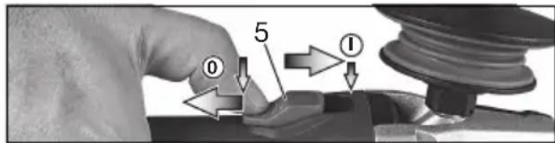
Switching on: Push the sliding switch forward. (5) For continuous activation, now tilt downwards until it engages.
Switching off: Press the rear end of the slide switch (5) and release it.
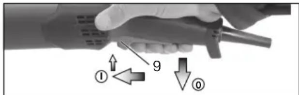
Machines with paddle switch (with dead man function):
Switching on: Slide the switch-on lock (10) in the direction of the arrow and press the trigger (9). Switching off: Release the trigger switch. (9)
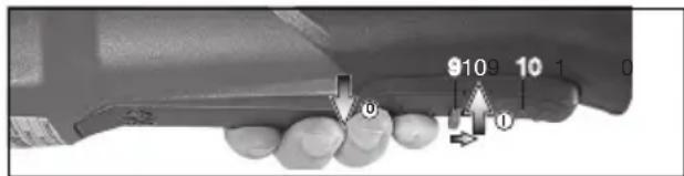
Machines with the designation W...RT: Torque activation (with dead man's lever)
Switching on: Slide the trigger switch (9) forwards and then push the trigger switch (9) upwards.
Switching off: Release the trigger switch (9).
Machines with the designation W...RT: Continuous operation (depending on features)
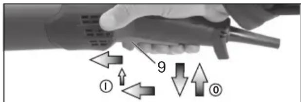
Switching on: Switch the machine on as described above. Now slide the trigger switch (9) forwards again and release in the front position to lock the trigger switch (9) (continuous operation).
Switching off: Push the trigger switch (9) upwards and release.
8.3 Working Directions
Grinding and sanding operations:
Press down the machine evenly on the surface and move back and forth so that the surface of the workpiece does not become too hot.
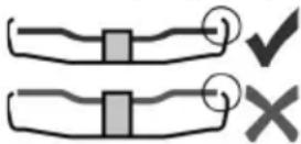
Rough grinding: position the machine at an angle of 30^ - 40^ for the best working results.
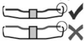
Cutting-off operations:
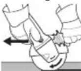
Always work against the run of the disc (see illustration). Otherwise there is the danger of the machine kicking back from the cut out of control. Guide the machine evenly at a speed
suitable for the material being processed. Do not tilt, apply excessive force or sway from side to side.
Wire brushing:
Press down the machine evenly.
8.4 Rotate gear housing
See illustration D on page 3.
- Disconnect from the power supply.
- Unscrew the fastening screw (a) of the lever (15). Remove the screw, lever (with its sheet metal part) and put aside.
- Unscrew the 4 gear housing screws (b). CAUTION! Do not remove the gear housing!
- Turn the gear housing to the desired position without removing it.
- Screw in the 4 gear housing screws (b) in the available threads! Tightening torque = 3.0 Nm +/- 0.3 Nm.
- Slide the spring that pushes the lever in position to the side and re-insert the lever (15) (with its sheet metal part), and fix with the fastening screw (a). Tightening torque = 5.0 Nm +/- 0.5 Nm. Check the lever for correct function: it has to be under spring tension.
9. Cleaning
It is possible that particles deposit inside the power tool during operation. This impairs the cooling of the power tool. Conductive build-up can impair the protective insulation of the power tool and cause electrical hazards.
The power tool should be cleaned regularly, often and thoroughly through all front and rear air vents using a vacuum cleaner or by blowing in dry air.
Prior to this operation, separate the power tool from the power source and wear protective glasses and dust mask.
10. Troubleshooting
Machines with VTC and TC electronics:
The electronic signal display lights up and the load speed decreases (not W...RT). (7) There is too much load on the
machine! Run the machine in idling until the electronics signal indicator switches off.

The machine does not start. The electronic signal display (7) (depends on model) flashes. The restart protection is
active. If the mains plug is inserted with the machine switched on, or if the power supply is restored following an interruption, the machine does not start up. Switch the machine off and on again.
11. Accessories
Use only genuine Metabo accessories. See page 6.
Use only accessories which fulfil the requirements and specifications listed in these operating instructions.
A Cutting guard clip / guard for cut-off grinding
Designed for work with cutting disc and diamond cutting discs. Once the cutting guard clip is fitted, the safety guard becomes a cutting guard.
B Extraction guard for cut-off grinding
Designed for cutting through stone slabs with diamond cutting discs. With nozzle for extracting stone dust using a suitable extraction unit.
C Extraction guard for surface grinding
Intended for grinding of concrete, screed, wood and plastics with diamond cup wheels and/or fibre discs and suitable sanding plates. With nozzle for extracting stone, wood and plastic dust using a suitable extraction unit. Not suitable for extracting sparks or for grinding of metals.
D Dust filter
The fine mesh filter prevents coarse particles from entering the motor housing. Remove regularly and clean.
E Hand protection
Intended for work with backing pads, sanding plates, wire brushes and support plates, sanding pads, wire brushes and diamond Drill Bits for tiles.
Install hand guard under the additional side-mounted handle.
F Multiple position bar for side handle
Permits numerous handle positions.
G Bar side handle
For a complete range of accessories, see www.metabo.com or the catalogue.
12. Repairs

Repairs to electrical tools must be carried out by qualified electricians ONLY!
If the connection lead is damaged, it must be replaced by a special connection lead.
Contact your local Metabo representative if you have Metabo power tools requiring repairs. For addresses see www.metabo.com.
You can download a list of spare parts from www.metabo.com.
ENGLISHen
13. Environmental Protection
The generated grinding dust may contain harmful substances. Dispose appropriately.
Observe national regulations on environmentally compatible disposal and on the recycling of disused machines, packaging and accessories.

Only for EU countries: Never dispose of power tools in your household waste! In accordance with European Directive 2012/
19/EU relating to electrical and electronic waste and implementation of national law, used electrical tools must be collected separately and disposed of in an environmentally friendly manner at recycling centres.
14. Technical Specifications
Explanatory notes on the specifications on page 4. Changes due to technological progress reserved. = max. diameter of the accessory
t_max,1 = max. permitted thickness of the clamping shank on accessory when using 2-hole nut (13)
t_max,2 = max. permitted thickness of clamping shank on accessory when using "Quick" clamping nut (1)
t_max,3 = roughing disc/cutting disc: max. permitted thickness of accessory
M = s p i n
I = length of the grinding spindle
n^*= no-load speed (maximum speed)
n_V^*=no-load speed (adjustable)
P_1 = rated input power
P_2 = power output
m = weight without mains cable
Measured values determined in conformity with EN 60745.
□ Machine in protection class II
\~ AC Power
* Machines with the designation WE... : Energy-rich, high-frequency interference can cause fluctuations in speed. The fluctuations disappear, however, as soon as the interference fades away.
The technical specifications quoted are subject to tolerances (in compliance with the relevant valid standards).
Emission values
These values make it possible to assess the emissions from the power tool and to compare different power tools. Depending on the operating conditions, the condition of the power tool or the accessories, the actual load may be higher or lower. For assessment purposes, please allow for breaks and periods when the load is lower. Based on the adjusted estimates, arrange protective measures for the user e.g. organisational measures.
Vibration total value (vector sum of three directions) determined in accordance with EN 60745:
a_h, SG = Vibration emission value (surface grinding)
a_h,DS = Vibration emission value (sanding with sanding plate)
a_h,P = Vibration emission value (polishing)
K_h,SG/DS/P = Uncertainty (vibration)
Typical A-effective perceived sound levels:
L_pA = Sound - pressure level
L_WA^P = Acoustic power level
K_pA, K_WA = Uncertainty
During operation the noise level can exceed 80 dB(A).

Wear ear protectors!
d l e t h r
Notice originale
a_h,P = vibrationsemission (Polering)
K_h,SG/DS/P = u s i k k e r h e d (v i b r a t i o n)
Zwluwtf δgwnh6tpp wchwnw6fhi yud ηtwnwl δcwlydug ymjpu, δh puwtf ypw6f gub6 pwyn6gtph hundwp shuunmukulnd μyntpnu' u6mu4nu1 epgwh μhgwmyju:
Zwunmih wejwnwn6ff6tp hwdwp oqwnqnpd6f hwnfwwpwnwnuw6 Lpwgnghs ywpnwq6tp: Tpw ebnphhj mwkth fhs fmbnlmnpjmup ndwn6h6tp hqnjm6ng6;
Oqwwqnptf hwúwwwnwnwlpwfi qncthwlpwf, qlneni htnwgúwghwpúmpwuf:
U lqukqgphf qhenunjudnlpjwi wwnhfuwip lwnwnpkjnl hknlujwi gnignuftpp
- sh upwhtf wpwnwnpyn qheni, uwaghghkph hnufp atp lww dtp annuulmujfnif qwhjny mfduuig ipmu, fuh ahp mnphf onh hnuwllfp hnuwflud qheni lww daughghkph ipmu,
- oqmwqnplf hudwwwnwnu]wul qnclhwi]uf hupfuwpuiif l/ lqud onh qunh2,
- wejwnwnlwjpp onwqhnvtl l wupgnhwn dwfptl ' oqnwnqnptlny qhcthml: Uyltllp hwi yhtllp hwlqnnwnllp, qhachli puapdiuglanl l:
- _nct|ln|ln| dfwptf l_1|wgtf gwk wqcuuqwghz hwqnluqn: Qdwfptl hwqnluqn phz|n|, [vht|n|] qwd [vnqwgwhltnl]:
5. ÇİGİhwGİNİP ĞİWPPWQPNİPŞMİĞ
Stu 19 2:
1 Upwqwutηδh₂ δωθθl *
2 26gwulw|wnwl
3 h_l
4 Plh ultnwljüwG lqn6wly
5 Unqughly qhnwnphh2 Uhwgnlü/Uügwunnlü *
6 F n G m l
7 _1 _2 _3 _4 _5 _6 _7 _8 _9 _10 _11 _12 _13 _14 _15 _16 _17 _18 _19 _20 _21 _22 _23 _24 _25 _26 _27 _28 _29 _30 _31 _32 _33 _34 _35 _36 _37 _38 _39 _40 _41 _42 _43 _44 _45 _46 _47 _48 _49 _50 *
Qucinquufis quinjufi hqlwulpu|wnwlh hudup
Un Un Un Un Un Un Un Un Un Un Un Un Un U U U U U U U U U U U U U U
Stu 3 Ump C
- UtnutL lswll (15) L utnud wwhtL: Nwcuuugh wwnjwgl (12) wupwgltL, hfgwku wwnltpulwd L:
zu3bfbthy
- Φηηλή δωμρι ραυπακρφλή υωευνωμωψης λωθωμργρ υχβίωμ, δήψιλή δωμρι ραυλακρωψη)h:
- Utnutl lsmllh h wmcunwgh2 wwnwjup wunntgltl wjfuhtu, npukuh qmh hwnludp uliu oqnuqnpdnh hqnhg:
- Ummiql, uwwcunjufih, uwwunjufih wdnlp qhpfp. Idwlp yklnf L ulkwnwlud jhih, uwwunjufip syklnf L anpulh:
Oqunwqnpl ulpwjwnulflp, npnfg unpnwwqhdp qlpwqwignuf h wqwnwqhly wwnwjgh wpnwwqhdp wnfujmq6 3,4 nd-nl: (hwkl hwlwnul)
htppwlwGmpjwdp)
7. 乙丙甲丙丙丙丙丙丙丙丙丙丙丙丙丙丙丙丙丙丙丙丙丙丙丙丙丙丙丙丙丙丙丙丙丙丙丙丙丙丙丙丙丙丙丙丙丙丙丙丙丙丙丙丙丙丙丙丙丙丙丙丙丙丙丙丙丙丙丙丙丙丙丙丙丙丙丙丙丙丙丙丙丙丙丙丙丙丙丙丙丙丙丙丙丙丙丙丙丙丙丙丙

^1 Wufug ulwqwnwl hwgtllp lww wupwgtllp uhen wsgwnkl unpfp kltqnpwnfuqnigwlgh hwgtlnl
Umpgwlq ympnwlq: Uwpfq wktnf t, wfi2wnmd ylhfwlmd ylhhi hyl hlp wliewpd:

Upquwutngh 106th (1) hufm#.

P1p lqmnq tf lqmfqftggtk, atqnftknj hjh M-Quick ukhwnlpduhi lqfwltp (4) dhuwfi wfi qlnqfnai, kph
Quick-wpuqwuknghs dwikhp (1) wkwnpplud L:
- U6gwnb1nig htnn qnp8hfp npnc dwdfw6wlq quunylniu L:
- Uphish hnhwuhwhwnulhp wunuhk, qnpupklp uuknukf hih M-Quick lwpuhp uukwnuhjs lphuhp (4): Quick-wpuwuknuhs dwllhp (1) hifnepnjsh paiwufndt l, dnn hlu wunnijwnnl h lwpnn k, wnugg lpwgnighs nd qnpdwnpblni lwwq npdhf oqnwnqnpduwu wunnuwwhwhfuhtl:
7.4 bplni uigfkpni] uufklih wupwgnul/huftnul (hwjnlmd t uwpfl uynklig)
bpln uigftpnl amfhlh (13) wdpugnl.
Bpln1 w6gftpnj dwgtlh 2 lqnqtpp mwppptp tb: Bpln1 w6gftpnj dwgtlh Gtpwqnnnwnwtl hih dpw htwnjwl htpw. Stu ls 2 Ulpw B
- X) fwpwl hhlwulwylwnwl6tp.
Omp tuq p pw u h ln qu w qu l wn w hp mw m ln u w p wg u h, t pl m w g f k pn u l dw th h tp nc u p (13) n ta ph yl tph n h pf nu l;
Opuqtaq tplm w6gftpnq dw6thp w9h9 gwnh h1h ypw, Gpw klm6p (13) ηbtqh 6tpfh ηhpfnj k:
bplm wigfhpml afmfthh cpgkunfu gkpflnuuf L, hul hupp khpup qluqh qlepl L: - B _Lh ulktnwlqni: bplqynuufhi nwpdwlh (14) oqfinpjuwup bplqn wfgftpnl dmfthe (13) aqtL dwuugmujg h ulwf mynnppjuwup:
Y) 2www.hnhwulwwlwnwhfkp
Z) U ^h wj6 W 9 -100
bplni wfgfkpnl dwfkljh hwfinl.
- b 1 h uklnnwlnq (nuu qnlq 7.1): b 2 hlqnqduh jnpawlh (14) oqlnprjwup klnac wlgfkpnei dwkllp (13) wpawlh dmunmgnjgh ylmf hmlpwnwlq mnppm pjmup;
8. Чршннід
U.6qwnnt#. u#ngfmlg utn#mlqnflmlp (9) utn#tkl ytbql ytbpl h pwg pn#tkl:
8.3 Zpwhm6q6tp mclwmm6ff hndmp
Oqunwqnptf uhwj gohqhgwL Metabo wqupwqw6tp: Stu 1,2 6:
Oqinwqnplf ahwfi wju nlnkgnjgnl fctlud qwhwlsftphu l zwihwlsftphu hwdwunwnuwwnn ywpwqwltp:
Lpwqnghy wupwqwklph wdpanqwulquf dpwqphf dwlnpwwlwnl hundwp wjgklhf www.metabo.com lwnf oqnllbf lwnwnlnqhg:
12. Чтрунпрногн
! LklnpwLwG qnpdhfGtph qtpwGnpqnqntuP lwpnn k lhpWwGnggltL shhwG hwdwnwnwnwUwG pGwqwLwnntd uqnhtphNghwl dwnWgwtwnl hnqhg:
Znuwthf shuagdufu dguwudw dwpp lwpptlh t qhnowphutl shuwjghwwmly Metabo qnpdwpwgwjfg lwpnd, npp lwpptlh t dtnf phtl Metabo uqwnuwplquw hwtwphg:
Metabo kltthwpwlpwq qnpδhffkph utpwfnpnqdwfu wghpwdtcunipjwq ηtwfniu ηhötf 2tp Metabo gtphwjnwmgzli: Zwugt6kpp lqwngtf www.metabo.com lqmfl qpm:
ΦwhwphGnn dwutph gwglp lwpnq bf gtpptngtl www.metabo.com lwjflg:
= oqunwqnpdynn ulpwylwnwlhl wnwnlblwqmjfi
t_max,1 = Ukqfmdh hwnlmdnd uqnlmnmlh mmnlklnqmlfi puqlnmptlh hnuunnlpjnl kplncl wfgflpnl dwldlh (13)oqmwnqnpddwls ηtwfmd:
(t_{max,2} = U_{\text{tr}} \text{d} \text{w} \text{f} \text{h} \text{h} \text{m} \text{u} \text{m} \text{d} \text{m} \text{u} \text{h} \text{u} \text{m} \text{u} \text{m} \text{u} \text{h} \text{h} \text{m} \text{u} \text{m} \text{u} \text{f} \text{h} \text{m} \text{u} \text{m} \text{u} \text{f} \text{h} \text{m} \text{u} \text{m} \text{u} \text{p} \text{h} \text{h} \text{h} \text{m} \text{u} \text{m} \text{u} \text{p} \text{h} \text{m} \text{u} \text{h} \text{m} \text{u} \text{m} \text{u} \text{q} \text{u} \text{m} \text{u} \text{q} \text{h} \text{s} \text{u} \text{m} \text{u} \text{f} \text{h} \text{l} \text{h} (1) _{\text{o}} \text{q}_{\text{n}} \text{m}_{\text{n}} \text{o}_{\text{n}} \text{o}_{\text{n}} \text{o}_{\text{n}} \text{o}_{\text{n}} \ u_{\text{n}} u_{\text{n}} u_{\text{n}} u_{\text{n}} u_{\text{n}} u_{\text{n}} u_{\text{n}} u_{\text{n}} u_{\text{n}} u_{\text{n}} u_{\text{n}} u_{\text{n}} u_{\text{n}} u_{\text{n}} u_{\text{n}} u_{\text{n}} u_{\text{n}} u_{\mathrm{n}} u_{\mathrm{n}} u_{\mathrm{n}} u_{\mathrm{n}} u_{\mathrm{n}} u_{\mathrm{n}} u_{\mathrm{n}} u_{\mathrm{n}} u_{\mathrm{n}} u_{\mathrm{n}} u_{\mathrm{n}} u_{\mathrm{n}} u_{\mathrm{n}} u_{\mathrm{n}} u_{\mathrm{n}} u_{\mathrm{n}} u_{\mathrm{n}} u_ {\mathrm{n}} u_{\mathrm{n}} u_{\mathrm{n}} u_{\mathrm{n}} u_{\mathrm{n}} u_{\mathrm{n}} u_{\mathrm{n}} u_{\mathrm{n}} u_{\mathrm{n}} u_{\mathrm{n}} u_{\mathrm{n}} u_{\mathrm{n}} u_{\mathrm{n}} u_{\mathrm{n}} u_{\mathrm{n}} u_{\mathrm{n}} u_{\mathrm{n}}
t_max,3 = _l,p/_n c l w i u w| n l/ _n u w| n l oq q i n u w| n l m l|k_l q j6 p j n k_l h n n jn i
M = h _Lh ψωραρωμ
I = _n l_n n_n h_1 h_1 l_1 p_1 l_1 w_1 n_1 p_1 j_1 n_1 f_1
n^* = _wpwwq p6pwgfh wnnljn6kph fw6wl (wnnljn6kph mnmhlklmqnj6 fw6wl)
n_V^* = _wpwwpfpugfhwpwwjnmfikphfmfwh (lwpww|n_pi|n_q)
P_1 = U_fi u_fi u_w u_f d k_pg u_n h_qn n_p p_j n_t f_i
P_2^' = S_pn|nn hqnpnlpjnlifi
m̄ = φwc wnw6g u6n1g6w6 lwph
QwphLh dhwlnpGtp puu EN 60745 Gnpsh:
□ 9nph wfucinwufnlprjwh ll qwh
\~ _nhhnhwlwli hnuwif
* Uwpfip WE... wfu(wu)wguencifiq 'tglpqhwnajh hupnluun pwpap hwguwwhwqntpjwdp fwugqwpniutgtpp lwpnq tg wnnijngtph fwguwlh wnwnwgiutgtp wnngwggtl: Tpwgf lphlg hwgbtwnw6h, tpp fwugqwpniutgtpp ytpw6h6:
Lc u w d o k l u f h l u l w l u f p n l u l u n p l l h ct n l u f t p (hw ^ w ^ w ^ w ^ w ^ w ^ g ^ n ^ n ^ n ^ w ^ w ^ b ^ h ^ ):
Upmuftkunnuliflph wpdkffikp
Cetudwpdtfgtpqofnipjwnp hguwulnp t unwfuwr l huwdtuwntl wju qnpdhfnl l wjl qnpdhgtpnl wejwnuwfgh phnn wpwnwftwniugtph fwgmhgtppp: Cun hhpwnndwg wpnjnfwgtgtp, qnpdhfli yhfwmlh l hhpwnwlqn wqmpqwgtph' jhnlnjnniu, utdsmniu knu fijmqnul t jwnwnmgh wpwnwktwniugtph fwgwlp: Zucjwplyh dwnuwglh hwclh unlf ggnuhgniugtpp l gwdp ptngwdnipjwiq wejwnuwfgwjhg jhnltpp: Uwnwnlp wpdtfgtp uwnwfwlng htwn oqnwwqnpdnnh
huāwùn àlnfēuŋpík f huāwùnwénwúwǔ wùwénwúhý ûhōngūlp guìl hòuqúwúlpwyswúwǔ ûhōngūlp:
Sunnufinulph ph phhunlp wpdhp (kph nqnupjnlghph qhlpnnpujhli qnuup)' huudwujfi EN 60745 linpih.
a_h,SG = S_wnwfnclghph wpdf (U_wltpbtgph hqlncl)
a_h,DS = S_www6m166tp|wpdtf (Zq|wulpw|wnulq|hqlnuf)
a_h,P = S_winwifnlflkph wpdlf ( _wjlkgnlf )
K_h,SG/DS/P = U.Gl_WjmGmPjmG(wwwGmdfgtp)
Uqimly A-qwuh wihly dwwwnwh.
L_pA = U.lqmmgh f6cufml wlmqmpnl
L_WA = U_nu_nl_h h_qn_pn_lp_jw_i u_wl_wp_nw_l
K_pA, K_WA = S_wwwGmlf
Uc|wmm6f| p6pmgfm| wndm|h wun|fbw6p lqmw|k qtpwqwfg| 80 nf (U):

Qupunhp lptl wwcunwghs whug2whwl:
EAC
Shukhupjuli qlinpph huiuup.
Zmifuuqmmu|oufunpjmfi hmi|uuumqhp.
"Uthunupn bdpwuhu" UNL
Phluuunui, 127273, Uulj]w
natural_image
Close-up of a hand holding a metallic object with a curved edge (no visible text or symbols)
- Original instructions
- Declaration of Conformity
- Specified Use
- General Safety Instructions
- Special Safety Instructions
- Safety Warnings Common for Grinding, Sanding, Wire Brushing or Abrasive Cutting-Off Operations:
- Use
- Kickback and Related Warnings
- Safety Warnings Specific for Grinding and Abrasive Cutting-Off Operations:
- Additional Safety Warnings Specific for Abrasive Cutting-Off Operations:
- ENGLISHen
- Safety Warnings Specific for Sanding Operations:
- Only for WEV 15-125 Quick HT, WEV 15-125 Quick Inox, WEV 17-125 Quick Inox RT: Safety Warnings Specific for Polishing Operations:
- Safety Warnings Specific for Wire Brushing Operations:
- Additional Safety Instructions:
- Reducing dust exposure:
- Overview
- Commissioning
- Attaching the additional handle
- Attach the safety guard
- Safety guard for grinding
- Attaching the grinding disc
- Locking the spindle
- Placing the grinding wheel in position
- Securing/Releasing the "Quick" clamping nut (depending on features)
- Releasing the clamping nut (1):
- Securing/Releasing the 2-hole nut (depending on features)
- Securing the 2-hole nut (13):
- - X) For thin grinding discs:
- Y) For thick grinding discs:
- Z) Only for W 9-100:
- Releasing the 2-hole nut:
- Use
- Adjusting the speed (depending on features)
- Brush: medium speed
- Switching On and Off
- Machines with slide switch:
- Machines with paddle switch (with dead man function):
- Machines with the designation W...RT: Torque activation (with dead man's lever)
- Machines with the designation W...RT: Continuous operation (depending on features)
- Working Directions
- Grinding and sanding operations:
- Cutting-off operations:
- Wire brushing:
- Rotate gear housing
- Cleaning
- Troubleshooting
- Accessories
- A Cutting guard clip / guard for cut-off grinding
- B Extraction guard for cut-off grinding
- C Extraction guard for surface grinding
- D Dust filter
- E Hand protection
- F Multiple position bar for side handle
- G Bar side handle
- Repairs
- Environmental Protection
- Technical Specifications
- Emission values
- Notice originale
- ÇİGİhwGİNİP ĞİWPPWQPNİPŞMİĞ
- Stu 19 2:
- Qucinquufis quinjufi hqlwulpu|wnwlh hudup
- zu3bfbthy
- 乙丙甲丙丙丙丙丙丙丙丙丙丙丙丙丙丙丙丙丙丙丙丙丙丙丙丙丙丙丙丙丙丙丙丙丙丙丙丙丙丙丙丙丙丙丙丙丙丙丙丙丙丙丙丙丙丙丙丙丙丙丙丙丙丙丙丙丙丙丙丙丙丙丙丙丙丙丙丙丙丙丙丙丙丙丙丙丙丙丙丙丙丙丙丙丙丙丙丙丙丙丙丙
- bplni uigfkpni] uufklih wupwgnul/huftnul (hwjnlmd t uwpfl uynklig)
- Y) 2www.hnhwulwwlwnwhfkp
- Z) U h wj6 W 9 -100
- bplni wfgfkpnl dwfkljh hwfinl.
- Чршннід
- Zpwhm6q6tp mclwmm6ff hndmp
- Чтрунпрногн
- Upmuftkunnuliflph wpdkffikp
- EAC
Brand : METABO
Model : WEP 17-125 Quick
Category : Sander