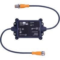
CR3122 - Industrial communication gateway IFM - Free user manual and instructions
Find the device manual for free CR3122 IFM in PDF.


User questions about CR3122 IFM
0 question about this device. Answer the ones you know or ask your own.
Ask a new question about this device
Download the instructions for your Industrial communication gateway in PDF format for free! Find your manual CR3122 - IFM and take your electronic device back in hand. On this page are published all the documents necessary for the use of your device. CR3122 by IFM.
USER MANUAL CR3122 IFM
Operating instructions
ISOBUS gateway
CR3122
Contents
1 Preliminary note 3
1.1 Symbols used 3
1.2 Warnings.... 3
2 Safety instructions.... 4
3 Intended use.... 5
3.1 Properties 5
4 Function 6
4.1 Application example 6
5 Installation.... 7
6 Electrical connection.... 8
6.1 Connection accessories 8
6.2 Connection technology 8
7 Set-up 9
8 Programming 10
8.1 Required documentation.... 10
8.2 Visualisation elements 10
8.2.1 Defining the title of a data mask 10
8.2.2 Issuing warnings.... 11
8.2.3 Adapting the softkey mask 12
8.2.4 Defining the footer.... 13
8.2.5 Defining operating elements 14
8.2.6 Defining numeric input fields 15
8.2.7 Defining numeric input fields with units 16
8.2.8 Defining the output of numerical values. 17
8.2.9 Defining the output of numerical values with units.... 18
8.2.10 Defining the curved bar chart 19
8.2.11 Defining the linear bar chart 20
8.2.12 Defining the pointer object.... 21
8.2.13 Managing colour settings 22
9 Maintenance, repair and disposal 24
1 Preliminary note
You will find instructions, technical data, approvals and further information using the QR code on the unit / packaging or at documentation.ifm.com.
1.1 Symbols used
√ Requirement
Instructions
Reaction, result
[...] Designation of keys, buttons or indications
→ Cross-reference

Important note
Non-compliance may result in malfunction or interference.

Information
Supplementary note
1.2 Warnings
Warnings indicate the possibility of personal injury and damage to property. This enables safe product handling. Warnings are graded as follows:

WARNING
Warning of serious personal injury
▷ If the warning is not observed, fatal and serious injuries are possible.

CAUTION
Warning of minor to moderate personal injury
▷ If the warning is not observed, minor to moderate injuries are possible.
ATTENTION
Warning of damage to property
▷ If the warning is not observed, damage to property is possible.
2 Safety instructions
- The unit described is a subcomponent for integration into a system.
- The system architect is responsible for the safety of the system.
-
The system architect undertakes to perform a risk assessment and to create documentation in accordance with legal and normative requirements to be provided to the operator and user of the system. This documentation must contain all necessary information and safety instructions for the operator, the user and, if applicable, for any service personnel authorised by the architect of the system.
-
Read this document before setting up the product and keep it during the entire service life.
- The product must be suitable for the corresponding applications and environmental conditions without any restrictions.
- Only use the product for its intended purpose (→ Intended use).
- If the operating instructions or the technical data are not adhered to, personal injury and/or damage to property may occur.
- The manufacturer assumes no liability or warranty for any consequences caused by tampering with the product or incorrect use by the operator.
• Installation, electrical connection, set-up, programming, configuration, operation and maintenance of the product must be carried out by personnel qualified and authorised for the respective activity. - Protect units and cables against damage.
- Replace damaged units, otherwise the technical data and safety will be impaired.
- Observe applicable documents.
3 Intended use
The device serves as an interface between an agricultural vehicle (tractor) and an add-on unit. The ISOBUS gateway exchanges data bidirectionally between the Virtual Terminal (VT) (ISOBUS) and the add-on unit or controller (CAN bus).
3.1 Properties
- Closed plastic housing for mounting on the add-on unit inside or outside a control cabinet (IP67)
- Configurable ISOBUS visualisation via IEC 61131 application
4 Function
The unit fulfils the following functions:
• 1 CAN interface with ISO11783 protocol (ISOBUS)
• 1 CAN interface with CAN layer 2 support (CAN bus → control)
• Transmission of the designed data masks (IOP files) to the VT (Virtual Terminal) via ISOBUS
• Transfer of the visualisation configuration from the controller to the VT
- Bidirectional communication between the VT (ISOBUS) and the control on the add-on unit (CAN bus)
- Transmission of values and commands from the controller, display on the VT
- Transmission of inputs and actions from the user at the VT to the controller
• Support for the bidirectional Task Controller (TC) communication
- TC Basic (TC-BAS)
– TC Geographic (TC-GEO)
– TC Section Control (TC-SC)
4.1 Application example

5 Installation

▶ Disconnect the power of the machine before installation.

▶ For installation choose a flat mounting surface.

The following applies to all types of mounting:
The responsibility for the compliance with the requirements concerning mounting of the device in the application with regard to shock, vibration, acceleration and weight lies with the system architect.
▶ Fix the unit to the mounting surface using 4 M4 mounting screws and washers.

Fig. 1: Installation
6 Electrical connection

The unit must be connected by a qualified electrician.
▶ Observe the national and international regulations for the installation of electrical equipment.
▶ Disconnect power.
▶ Connect the unit as follows:

Fig. 2: Electrical connection
1: 5-pole M12 connector → ISOBUS
- Pin 1: not used
- Pin 2: VBB
- Pin 3: GND
- Pin 4: CAN_H
- Pin 5: CAN_L
2: 5-pole M12 socket → CAN bus
- Pin 1: not used
- Pin 2: not used
- Pin 3: not used
- Pin 4: CAN_H
- Pin 5: CAN_L
6.1 Connection accessories
More information about available accessories at www.ifm.com
6.2 Connection technology

Observe all notes on connection technology.
▶ Note the device label.
▶ Use M12 connectors with gold-plated contacts.
▶ The M12 connection parts in the device comply with the ingress resistance requirements of the standard EN 61076-2-101. To adhere to the protection rating, only cables certified to this standard must be used. The system architect undertakes to ensure the ingress resistance of cables they have cut to length.
▶ Carry out the fitting according to the indications of the cable manufacturer. The permitted maximum is 10 Nm.
▶ During installation, place the M12 connector vertically so that the coupling nut will not damage the thread.
7 Set-up
After power on, the unit is ready for operation.
The operating status is signalled by the two LEDs.

1: LED power
2: LED status
Fig. 3: LEDs
| LED | Colour | Status | Designation |
| Power | off | Supply voltage too low. | |
| green | on | Waiting for connection to an ISOBUS-VT | |
| flashing | Communication with a ISOBUS-VT | ||
| red | on | Incorrect / missing product licence | |
| Status | off | Supply voltage too low. | |
| green | on | Unit in operating mode, connection interrupted | |
| flashing | Unit in operating mode, connection established | ||
| red | on | Communication error |
8 Programming
The basic procedure for programming is as follows:
▶ Program the application (CODESYS).
▶ Configure the visualisation (CODESYS).
▶ Load the application into the controller.
▷ Visualisation is automatically loaded onto the Virtual Terminal (VT) via the CR3122 (ISOBUS).
▷ In operation, bidirectional communication between VT (ISOBUS) and control (CAN bus) via the CR3122.
The CR3122 unit is supplied with IOP (Implement Object Pool) pre-installed. The configuration takes place exclusively via CODESYS with the help of the libraries.
8.1 Required documentation
The online help CODESYS is available for download on the Internet: www.ifm.com
A table with the icons is included in the help file.
In the download area, step-by-step instructions, icon overviews and sample projects are available for download.
8.2 Visualisation elements
In the following, the basic function blocks of the ifm_ISOBUS library are presented by means of examples. The input parameters must be adapted to the specific project. It is advisable to use variables instead of constant values in order to be able to change colours and numerical values at runtime.
Up to 12 data masks (pages) are available for configuration. Each data mask has 6 slots that can be filled with operating and display elements as required.
Basic functions can be configured for all data masks (pages) via operating elements in the footer as well as via softkeys on the left and right edges.
If a function module has a status output, the following status messages are possible:
- Initialisation
- Idle
- Operation
- Error
8.2.1 Defining the title of a data mask
The function module FB_DataMask_Title defines the title of a specific data mask (page).
Configuration example in CODESYS:

Visualisation example:


8.2.2 Issuing warnings
The function module FB_Warnings issues warning symbols as well as acoustic warnings.
The input parameter wIconWarning
The input parameter byState
Icon
• 0 = white (e.g. off)
• 1 = green (e.g. on)
• 2 = yellow (e.g. warning)
• 3 = red (e.g. alarm)
The input parameter xAcoustic
Warning switches the acoustic warning on/off. If the acoustic warning is switched on, the following signal tones are possible:
- If at least one input parameter byState
Iconhas the value 2, a warning tone will sound. - If at least one input parameter byState
Iconhas the value 3, an alarm tone will sound.
Configuration example in CODESYS:
FB_Warnings
| ifm_ISOBUS. Warning. Hydraulic Filter | wIconWarning1 | State Warnings |
| 0 | byState Icon1 | |
| ifm_ISOBUS. Warning. Hydraulic Level | wIconWarning2 | |
| 1 | byState Icon2 | |
| ifm_ISOBUS. Warning. Hydraulic Pressure | wIconWarning3 | |
| 2 | byState Icon3 | |
| ifm_ISOBUS. Warning. Hydraulic Temperature | wIconWarning4 | |
| 3 | byState Icon4 | |
| ifm_ISOBUS. Warning. Coolant Level | wIconWarning5 | |
| 0 | byState Icon5 | |
| ifm_ISOBUS. Warning. Coolant Temperature | wIconWarning6 | |
| 1 | byState Icon6 | |
| ifm_ISOBUS. Warning. Break | wIconWarning7 | |
| 2 | byState Icon7 | |
| ifm_ISOBUS. Warning. Loading Volume | wIconWarning8 | |
| 3 | byState Icon8 | |
| ifm_ISOBUS. Warning. LowVoltage | wIconWarning9 | |
| 0 | byState Icon9 | |
| ifm_ISOBUS. Warning. Temperature | wIconWarning10 | |
| 1 | byState Icon10 | |
| ifm_ISOBUS. Warning. Tire | wIconWarning11 | |
| 2 | byState Icon11 | |
| ifm_ISOBUS. Warning. Undefined Error | wIconWarning12 | |
| 3 | byState Icon12 | |
| wIconWarning13 | ||
| byState Icon13 | ||
| wIconWarning14 | ||
| byState Icon14 | ||
| wIconWarning15 | ||
| byState Icon15 | ||
| wIconWarning16 | ||
| byState Icon16 | ||
| wIconWarning17 | ||
| byState Icon17 | ||
| wIconWarning18 | ||
| byState Icon18 | ||
| xAcoustic Warning | xAcoustic Warning | |
| xReset |
Visualisation example:

8.2.3 Adapting the softkey mask
The function block FB_Softkey
Mask defines the softkeys for all data masks (pages). A maximum of 12 softkeys can be configured. The actual appearance may differ from the example and depends on the manufacturer of the VT used.
The input parameter xSoftkey
The input parameter wID_IconSoftkey
The input parameter byColor
Icon
• 0 = black
- 1 = green
- 2 = yellow
• 3 = red
Configuration example in CODESYS:
| IFM_ISOBUS. FB_Softkey Mask | ||
| TRUE | xSoftkey1 | State |
| ifm_ISOBUS.w_Icons. Arrow_Up | wID_IconSoftkey1 | axSoftkey States |
| 0 | byColor Icon1 | |
| TRUE | xSoftkey2 | |
| ifm_ISOBUS.w_Icons. Arrow_Down | wID_IconSoftkey2 | |
| 1 | byColor Icon2 | |
| TRUE | xSoftkey3 | |
| ifm_ISOBUS.w_Icons. Arrow_Left | wID_IconSoftkey3 | |
| 2 | byColor Icon3 | |
| TRUE | xSoftkey4 | |
| ifm_ISOBUS.w_Icons. Arrow_Right | wID_IconSoftkey4 | |
| 3 | byColor Icon4 | |
| FALSE | xSoftkey5 | |
| ifm_ISOBUS.w_Icons. Arrow_TiltLeft | wID_IconSoftkey5 | |
| 0 | byColor Icon5 | |
| FALSE | xSoftkey6 | |
| ifm_ISOBUS.w_Icons. Arrow_TiltRight | wID_IconSoftkey6 | |
| 1 | byColor Icon6 | |
| TRUE | xSoftkey7 | |
| ifm_ISOBUS.w_Icons. Plus | wID_IconSoftkey7 | |
| 2 | byColor Icon7 | |
| FALSE | xSoftkey8 | |
| ifm_ISOBUS.w_Icons. Minus | wID_IconSoftkey8 | |
| 3 | byColor Icon8 | |
| TRUE | xSoftkey9 | |
| ifm_ISOBUS.w_Icons. Arrow_Up | wID_IconSoftkey9 | |
| 0 | byColor Icon9 | |
| FALSE | xSoftkey10 | |
| ifm_ISOBUS.w_Icons. Arrow_Down | wID_IconSoftkey10 | |
| 1 | byColor Icon10 | |
| TRUE | xSoftkey11 | |
| ifm_ISOBUS.w_Icons. Arrow_Left | wID_IconSoftkey11 | |
| 2 | byColor Icon11 | |
| FALSE | xSoftkey12 | |
| ifm_ISOBUS.w_Icons. Arrow_Right | wID_IconSoftkey12 | |
| 3 | byColor Icon12 | |
| xReset | xReset | |
Visualisation example:

8.2.4 Defining the footer
The function module FB_Footer defines the footer for all data masks (pages). A maximum of 4 controls can be configured in the footer.
The input parameter xButton
The input parameter wIconButton
The input parameter byColor
Icon
• 0 = black
- 1 = green
- 2 = yellow
• 3 = red
Configuration example in CODESYS:

Visualisation example:


8.2.5 Defining operating elements
The function module FB_Function
Creator_Button defines operating elements for a specific data mask (page). A maximum of 6 of these objects can be placed in a data mask.
The input parameter wID_IconButton
The input parameter byColor
Icon
• 0 = black
- 1 = green
- 2 = yellow
• 3 = red
The output parameter axButton
State contains the current states of the two operating elements.
Configuration example in CODESYS:

Visualisation example:


8.2.6 Defining numeric input fields
The function module FB_Function
Creator_Numeric
Input defines simple numeric input fields for a specific data mask (page). A maximum of 6 of these objects can be placed in a data mask.
The following data can be configured using the input parameters:
• Required data mask (page)
- Required slot
- Title
• Number of input fields (max. 2)
• Number of decimal places for the corresponding input field
- Initial value for the corresponding input field
• Name of the corresponding input field
The output parameter adw_Input
Values contains the entered values.
Configuration example in CODESYS:

Visualisation example:


8.2.7 Defining numeric input fields with units
The function module FB_Function
Creator_Numeric
Input_Long defines numeric input fields with unit specification for a specific data mask (page). A maximum of 3 of these objects can be placed in a data mask (slots 1, 3 and 5). The visualisation element also occupies the adjacent slot on the right.
The following data can be configured using the input parameters:
• Required data mask (page)
- Required slots
- Title
• Number of input fields (max. 2)
• Number of decimal places for the corresponding input field
- Initial value for the corresponding input field
• Name of the corresponding input field
• Unit for the corresponding input field
The output parameter adw_Input
Values contains the entered values.
Configuration example in CODESYS:

Visualisation example:


8.2.8 Defining the output of numerical values
The function module FB_Function
Creator_Numeric
Output defines the display of simple numerical values for a specific data mask (page). A maximum of 6 of these objects can be placed in a data mask.
The following data can be configured using the input parameters:
• Required data mask (page)
- required slot
- Title
• Number of output fields (max. 2)
• Number of decimal places for the corresponding output field
• Current value for the corresponding output field
• Name of the corresponding output field
Configuration example in CODESYS:
FB_Function
Creator_Numeric
Output

Visualisation example:
| Title Nm Out | |
| Value 1 | 510 |
| Value 2 | 520 |

8.2.9 Defining the output of numerical values with units
The function module FB_Function
Creator_Numeric
Output defines the display of simple numeric values with indication of the unit for a specific data mask (page). A maximum of 3 of these objects can be placed in a data mask (slots 1, 3 and 5). The visualisation element also occupies the adjacent slot on the right.
The following data can be configured using the input parameters:
• Required data mask (page)
- required slot
- Title
• Number of output fields (max. 2)
• Number of decimal places for the corresponding output field
• Current value for the corresponding output field
• Name of the corresponding output field
• Unit for the corresponding output field
Configuration example in CODESYS:

Visualisation example:


8.2.10 Defining the curved bar chart
The function module FB_Function
Creator_Arched
Bargraph defines the display of values in a curved bar chart for a specific data mask (page). A maximum of 6 of these objects can be placed in a data mask.
The following data can be configured using the input parameters:
• Required data mask (page)
- required slot
- Title
• Unit for the displayed value
- Current value
• Number of decimal places of the current value
- Target value
• Minimum value of the display
• Maximum value of the display
• Colour combination of the bar
• Line colour for displaying the target value
Configuration example in CODESYS:

Visualisation example:


8.2.11 Defining the linear bar chart
The function module FB_Function
Creator_Linear
Bargraph defines the display of values in a linear bar chart for a specific data mask (page). A maximum of 6 of these objects can be placed in a data mask.
The following data can be configured using the input parameters:
• Required data mask (page)
- required slot
- Title
• Unit for the displayed value
- Current value
• Number of decimal places of the current value
- Target value
• Minimum value of the display
• Maximum value of the display
• Colour combination of the bar
• Line colour for displaying the target value
Configuration example in CODESYS:
FB_Function
Creator_Linear
Bargraph

Visualisation example:


8.2.12 Defining the pointer object
The function module FB_Function
Creator_Meter defines the representation of values with a pointer for a specific data mask (page). A maximum of 6 of these objects can be placed in a data mask.
The following data can be configured using the input parameters:
• Required data mask (page)
- required slot
- Title
• Unit for the displayed value
- Current value
- Offset (for oscillating around a zero position, for example to visualise a slope)
• Number of decimal places of the current value
• Minimum value of the display
• Maximum value of the display
• Number of graduation marks in the scale
- Scale colour
- Pointer colour
Configuration example in CODESYS:

Visualisation example:


8.2.13 Managing colour settings
The function module FB_SetColors defines the colour representation of all data masks (pages).
For example, background, line and text colours can be configured via the input parameters.
Configuration example in CODESYS:

Visualisation example:

9 Maintenance, repair and disposal
Cleaning the unit:
▶ Disconnect the unit from the voltage supply.
▶ Clean the unit from dirt using a soft, chemically untreated and dry micro-fibre cloth.
The operation of the unit is maintenance-free.
Only the manufacturer is allowed to repair the unit.
▶ After use dispose of the device in an environmentally friendly way in accordance with the applicable national regulations.
- 1 PRELIMINARY NOTE
- 1.1 SYMBOLS USED
- 1.2 WARNINGS
- 2 SAFETY INSTRUCTIONS
- 3 INTENDED USE
- 3.1 PROPERTIES
- 4 FUNCTION
- 4.1 APPLICATION EXAMPLE
- 5 INSTALLATION
- 6 ELECTRICAL CONNECTION
- 6.1 CONNECTION ACCESSORIES
- 6.2 CONNECTION TECHNOLOGY
- 7 SET-UP
- 8 PROGRAMMING
- 8.1 REQUIRED DOCUMENTATION
- 8.2 VISUALISATION ELEMENTS
- 8.2.1 DEFINING THE TITLE OF A DATA MASK
- 8.2.2 ISSUING WARNINGS
- 8.2.3 ADAPTING THE SOFTKEY MASK
- 8.2.4 DEFINING THE FOOTER
- 8.2.5 DEFINING OPERATING ELEMENTS
- 8.2.6 DEFINING NUMERIC INPUT FIELDS
- 8.2.7 DEFINING NUMERIC INPUT FIELDS WITH UNITS
- 8.2.8 DEFINING THE OUTPUT OF NUMERICAL VALUES
- 8.2.9 DEFINING THE OUTPUT OF NUMERICAL VALUES WITH UNITS
- 8.2.10 DEFINING THE CURVED BAR CHART
- 8.2.11 DEFINING THE LINEAR BAR CHART
- 8.2.12 DEFINING THE POINTER OBJECT
- 8.2.13 MANAGING COLOUR SETTINGS
- 9 MAINTENANCE, REPAIR AND DISPOSAL
Brand : IFM
Model : CR3122
Category : Industrial communication gateway