
BPE6410X - Cooker BRANDT - Free user manual and instructions
Find the device manual for free BPE6410X BRANDT in PDF.

| Product type | Mixed gas + electric hob |
| Brand | Brandt |
| Model | BPE6410X |
| Gas burners | 4 burners: auxiliary (0.85 kW), semi-fast (1.50 kW), fast (2.35 kW), large fast (3.05 kW) - natural gas G20 power |
| Electric plate | 1 electric zone 1.50 kW - diameter 145 mm |
| Ignition | Electronic integrated into the knobs, with separate ignition button |
| Electrical supply | 220-240 V ~ 50 Hz, cable H05V2V2F 3x1 mm², fuse 10 A |
| Gas supply | Natural gas G20/G25 (20/25 mbar) or butane G30 (28-30 mbar) / propane G31 (37 mbar) - adaptable with supplied injectors |
| Overall dimensions (top) | W 60 x D 53 x H 5.8 cm |
| Overall dimensions (underside) | W 55 x D 47.5 x H 3.4 cm |
| Cut-out dimensions (worktop) | W 56 x D 49 cm |
| Table material | Enamel or stainless steel depending on version |
| Grid/support pan supports | Enamelled cast iron, removable |
| Safety devices | Flame extinction: manual re-ignition; no integrated gas safety (supervision required) |
| Routine maintenance | Clean burners and injectors with a stiff brush and a pin; electric plate with a greasy cloth |
| Not recommended cleaning | Steam cleaner, scouring sponge, abrasive products |
| Gas connection | Rigid copper tube or compliant metal/rubber hose (max length 2 m for flexible) |
| Electrical connection | Standardised IEC 60083 socket or omnipolar switch - earthing mandatory |
| Weight | About 12 kg (estimated) |
| Repairability index | Available on request (Brandt certified spare parts) |
Frequently Asked Questions - BPE6410X BRANDT
User questions about BPE6410X BRANDT
0 question about this device. Answer the ones you know or ask your own.
Ask a new question about this device
Download the instructions for your Cooker in PDF format for free! Find your manual BPE6410X - BRANDT and take your electronic device back in hand. On this page are published all the documents necessary for the use of your device. BPE6410X by BRANDT.
USER MANUAL BPE6410X BRANDT
natural_image
Black-and-white photo of a bowl with leaf garnish, surrounded by other bowls (no text or symbols visible)natural_image
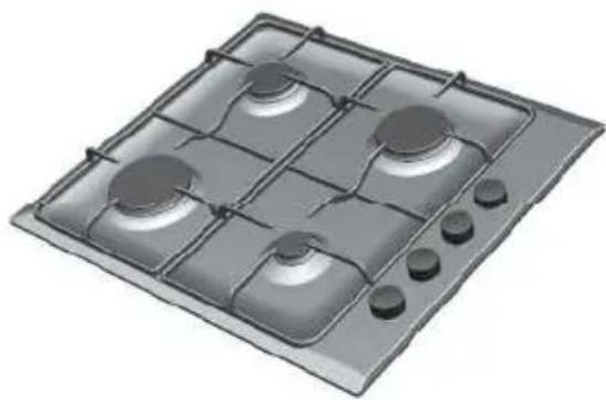
3D rendering of a four-gas stove with four circular vented fans and three control knobs (no text or symbols)Brandt

natural_image
Black-and-white photo of a bowl with leaf garnish, blurred bowls in background (no text or symbols)GUIDE D'INSTALLATION ET D'UTILISATION FR
Table de cuisson
natural_image
3D rendering of a four-gas stove with control panel and buttons (no text or symbols)Chère Cliente, Cher Client,

Important :
natural_image
Diagram of a circular device with directional arrows and star symbol, labeled Fig. 01 (no text or symbols on diagram itself)
Conseils
natural_image
Black-and-white photo of a bowl with leaf garnish, blurred bowls in background (no text or symbols)GUIDE FOR INSTALLATION AND USE EN
Cooking hob

natural_image
3D rendering of a gas stove with four panes and control buttons (no text or symbols)Dear Customer,
You have just acquired a BRANDT product and we would like to thank you.
We have designed and made this product with you, your lifestyle and your requirements in mind so that it meets your expectations. We have devoted our know-how, our innovative spirit and the passion that has been guiding us for over 60 years.
In an effort to ensure that our products meet your requirements in the best possible way, our Customer Relations department is at your disposal, to answer all your questions and to listen to all your suggestions.
Visit our website www.brandt.com where you will find our latest innovations, as well as useful and complementary information.
BRANDT is delighted to assist you every day and hopes you get the most out of your purchase.

Important: Before using your appliance, read this user guide carefully to familiarise yourself more quickly with its operation.

- Safety instructions 28

• Caring for the environment 31

- Description of your appliance 32

INSTALLING YOUR APPLIANCE
- Choice of location 33
- Fitting 33
- Tips for flush mounting 34
- Electric connection 35
- Gas connection 36
- Changing of gas supply 38

USING YOUR APPLIANCE
- Description of the worktop ____ 42
● Lighting the hob ____ 43 - Cookware suitable for the gas burners 44
- Cookware for electric plate 45
- Switching on the electric plate 45

DAILY CARE OF YOUR APPLIANCE
- Maintaining your appliance 46

SPECIAL MESSAGES, INCIDENTS
- During use ____ 47
COOKING GUIDES
Gas cooking guide 48
- Electric cooking guide 48

AFTER-SALES SERVICE
- Service calls ____ 52
IMPORTANT SAFETY INSTRUCTIONS - READ CAREFUL-LY AND RETAIN FOR FUTURE USE.
This user guide is available for download on the brand's website.
We have designed this cooking hob for use by private individuals in their homes.
This appliance must be installed in compliance with currently applicable regulations and used only in a well-ventilated location.
Consult this guide before installing and using your appliance.
Never leave the appliance unattended when in use.
These cooking hobs are intended exclusively for cooking beverages and foodstuffs and do not contain any asbestos-based materials.
This appliance is not connected to a device for evacuating combustion products. It must be installed and connected in compliance with the regulations in force. Particular attention must be given to the guidelines concerning ventilation.
The use of a gas cooking appliance produces heat and humidity in the room where it is located. Ensure that the kitchen is well-ventilation orifices open.
The use of a gas cooking appliance produces heat and humidity in the room where it is located. Ensure that the kitchen is well-ventilated: keep mechanical ventilation orifices open. Intensive and prolonged
use of the appliance may require additional ventilation, for example opening a window, or more efficient ventilation, for example by increasing the power of the mechanical ventilation if present.
Do not store CLEANING products or FLAMMABLE products (aerosol cans or pressurised containers, as well as papers, cookbooks, etc.) in the cabinet underneath your cooking hob.
If the hob has been installed over a drawer, we recommend that you avoid using it to store flammable items (plastics, papers, aerosol cans, etc.).
If you plug electrical appliances into a socket close to the hob, ensure that no cable comes into contact with the hotplates and burners.
The electrical plug must remain accessible after installation.
The CE mark is affixed to these hobs.
This appliance is designed to be installed on a work surface only.
WARNING:
Only use protection systems designed by the manufacturer of the cooking appliance or systems mentioned by the manufacturer of the appliance in the user guide for the intended use, or use the protection system integrated into the appliance. Use of unsuitable protection systems could cause accidents.
As a safety measure, remember to shut off the mains gas supply or the butane/propane gas cylinder when not in use.
When a knob becomes difficult to turn, do not force it. Request an emergency service call for the installater.
This appliance may be used by children aged 8 years and older, and by persons with impaired physical sensorial or mental capacities, or without experience or knowledge, if they are supervised or have received prior instructions on how to use the appliance safely and have understood the risks involved. Children must not be allowed to play with the appliance. Cleaning and maintenance operations must not be carried out by children without supervision.
Do not use a steam cleaner.
It must be possible to disconnect the appliance from the power supply, either using a plug or by fitting a switch on the fixed wiring system in accordance with installation rules.
Do not use containers whose surfaces extend past the edges of the hob.
We do not recommend using any hob protection mechanism.
Children must be supervised to prevent them from playing with the appliance.
If the power supply lead is damaged, it must be replaced by a H05V2V2F cable and three 1 mm² conductors.
This unit is not intended to be operated using an external timer or a separate remote control system.
Before installation, ensure that the conditions of local distribution (gas type and pressure) and the settings of the appliance are compatible.
Installation should only be undertaken by qualified fitters and technicians.
This hob is compliant with standard EN 60335-2-6 relating to the heating of cabinets and the Class 3 standard with regard to installation (as per standard EN 30-1-1).
CAUTION: The cooking process must be monitored. A short cooking process must be continuously monitored.
When not monitored, cooking on a cooking plate with fat or oil can be dangerous and may cause a fire.
WARNING: only use protection systems designed by the manufacturer of the cooking appliance or systems mentioned by the manufacturer of the appliance in the user guide for the intended use, or use the protection system integrated into the appliance. Use of unsuitable protection systems could cause accidents.
So that you can easily locate any reference numbers for your appliance, we recommend that you make a note of them on the "After-Sales Service and Customer rations" page (this page also explains where this information may be found on your appliance).
WARNING: the appliance and the accessible parts of it will become hot during use. Be careful not to touch the heated elements. Children under the age of 8 years must not be allowed to touch the appliance, unless they are supervised continually.
Never use aluminium foil for cooking. Never place products wrapped in aluminium foil or in aluminium trays onto your hob. The aluminium will melt and permanently damage your appliance.
The conditions for setting this appliance are described on the label inside the bag or on the rating plate.
WARNING: it is dangerous to cook with oil or fat if the hob is left unattended, as this may cause a fire. Do not attempt to extinguish a fire with water but switch off the appliance, then cover the flame with a lid or a fire blanket.
Fire hazard: Do not store objects on the cooking surfaces.
This appliance's packing materials are recyclable. Recycle them and play a role in protecting the environment by depositing them in local authority containers provided for this purpose.
Your appliance also contains various recyclable materials. It is therefore marked with this logo to indicate that, in European Union countries, used appliances must not be mixed with other waste. Appliance recycling organised by your manufacturer will thus be carried out in optimum conditions, in accordance with European directive 2002/96/CE relating to electrical and electronic equipment waste. Contact your local council or your retailer to find out the drop-off points for used appliances that are nearest to your home.
We thank you for your help in protecting the environment.
• DESCRIPTION OF THE HOB
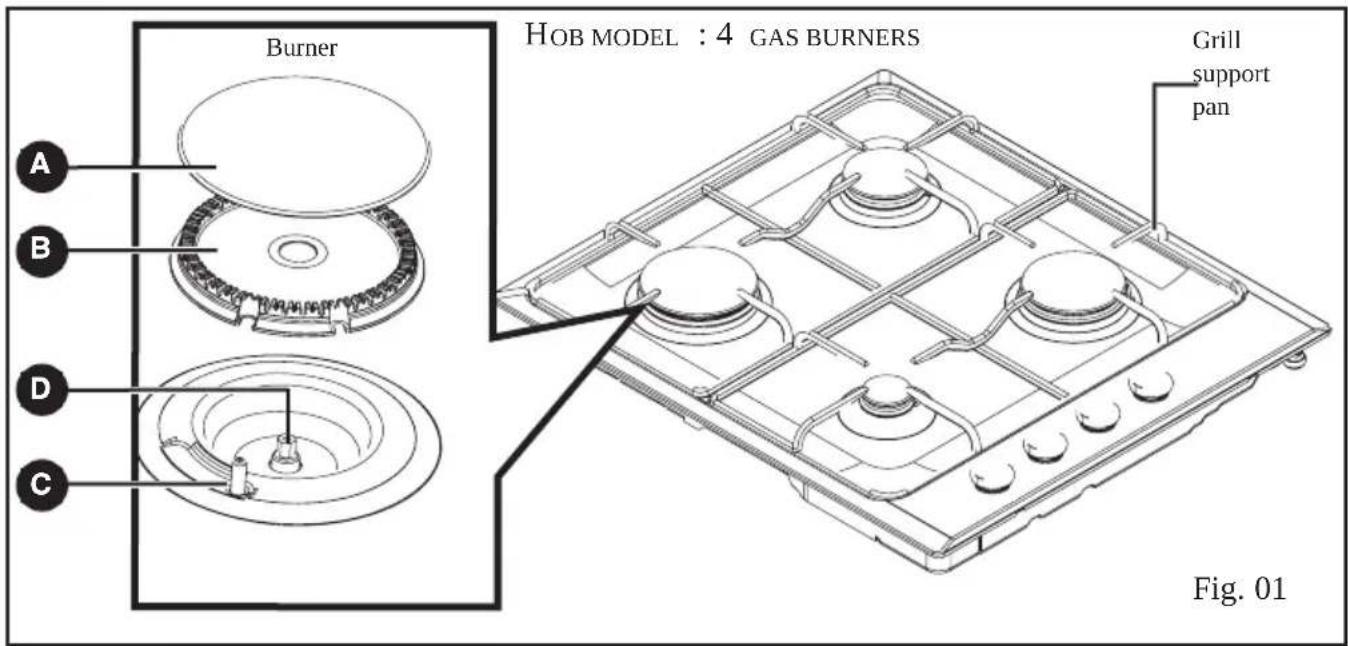
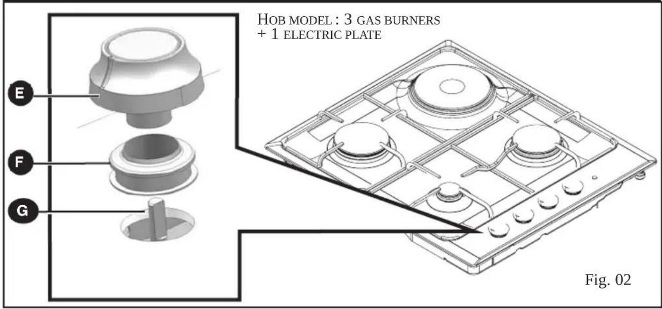
A Burner cover
D Injector
G Tap
B Burner head
E Knob
C Thermocouple
F Gasket
Tip This Guide to Installation and Use is valid for several models. Minor differences in details and fittings may emerge between your appliance and the descriptions provided.
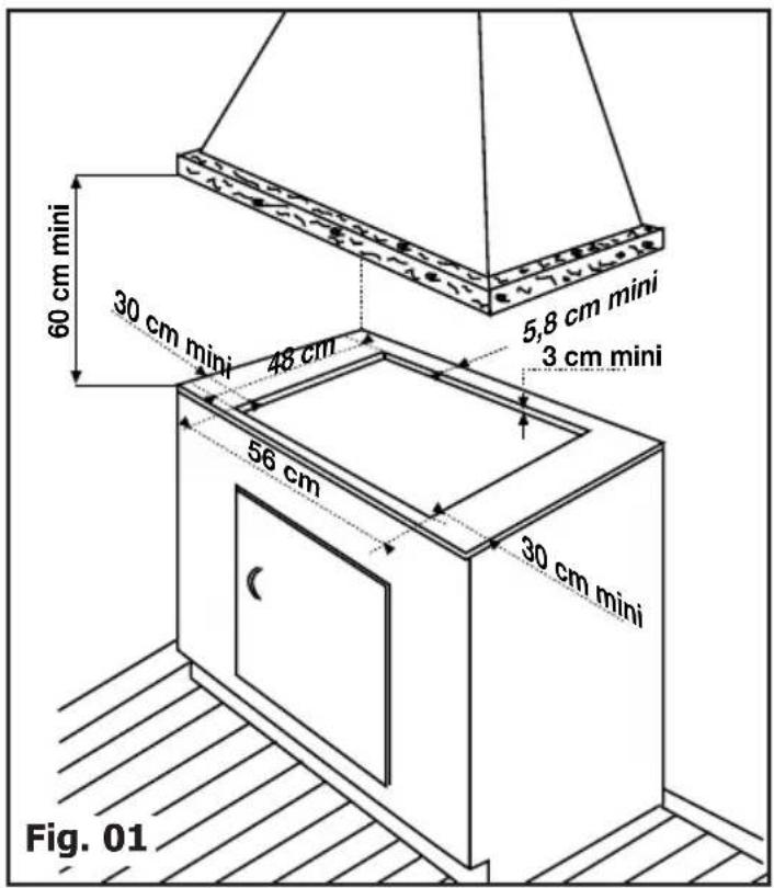
Your appliance should be flush mounted in the surface of a support cabinet that is a minimum of three cm thick, made of a material that resists heat or that is covered with such a material.
So as not to disturb movement of cooking utensils, there should not be to the right or left or back any obstacle within 30 cm of the hob.
If a horizontal divider wall is positioned under the hob, it should be placed between 10 cm and 15 cm away from the top of the work top. In any event, do not store aerosol cans or containers under pressure in any compartment that may exist under the hob (See "Safety Recommendations" chapter).
- FLUSH MOUNTING
Follow the diagram (Fig. 01).
— Remove the pan supports, the burner covers and burner heads, noting their positions.
| APPLIANCE | |||
| Width | Depth | Thickness | |
| Cut cabinet | 56 cm | 49 cm | next cabinet |
| Total dimensions above the work top | 60 cm | 53 cm | 5,8 cm |
| Total dimensions below the work top | 55 cm | 47,5 cm | 3,4 cm |
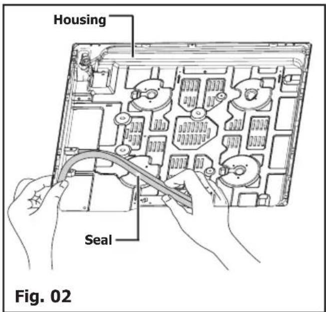
— Turn the hob over and carefully place it on top of the opening in the cabinet so as not to damage the knobs and spark plugs. — To ensure a tight seal between the housing and the work top, glue the foam seal along the exterior edge of the housing before installing the hob (Fig. 02).
• TIPS FOR FLUSH MOUNTING
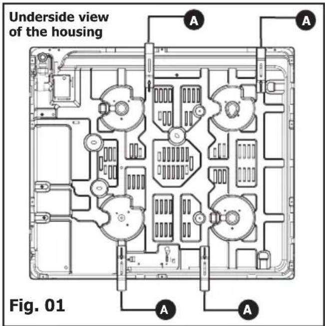
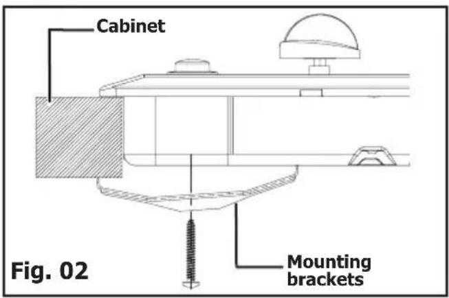
A Mounting brackets
- Place your hob in the opening of the support cabinet, carefully pulling the table towards you.
- Reposition the burner heads, burner covers and pan supports on the hob.
- Connect your hob to the gas supply (See "Gas Connection" chapter) and to the power supply (See "Electrical Connection" chapter).
If you wish, you can immobilise the hob using the four mounting brackets delivered with a screw (Fig. 02) to attach them to the four corners of the housing. You must use the holes provided for this purpose, according to the diagram above (Fig. 01).
Stop screwing when the mounting bracket starts to become deformed. Do not use a screwdriver.
• ELECTRICAL CONNECTION
The oven must be plugged in using a standardized power cable with 3 conductors each 1,5 ~mm^2 (1 ph + 1 N + ground) which must be connected to the 220\~240 Volt network by means of a standardized IEC 60083 power socket or a single-pole cut-off device in compliance with installation regulations. The safety wire (green-yellow) is connected to the appliance's ground terminal and must be connected to the installation's ground lead.
— The plug of the electrical outlet must be accessible after installation.
| CROSS-SECTION OF CABLE TO BE USED | |
| 220-240 V~50 HzGas and dual | |
| H05V2V2F - T90 cable | 3 conductorsincluding 1 ground |
| Cross-section of the conductors in mm2 | 1 |
| Fuse | 10 A |
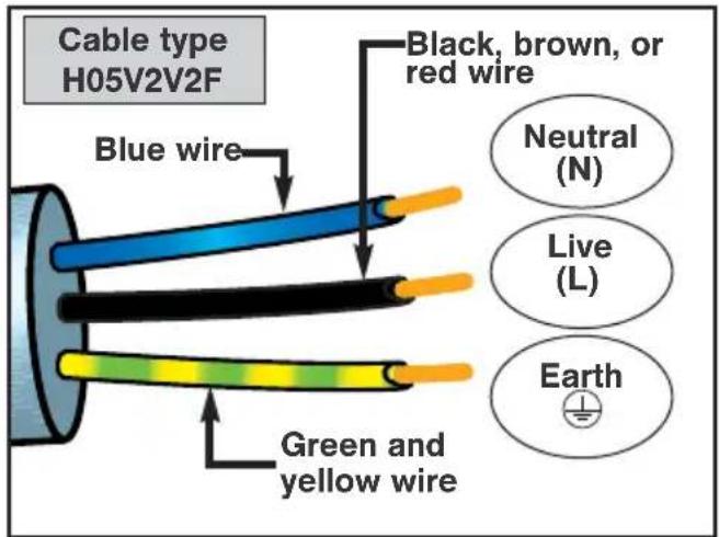
Connect the wires to the electricity supply making sure that the different-coloured wires are in the right order.

Attention
— The safety wire (green/yellow) is connected to the appliance's ground terminal and must be connected to the ground lead of the electrical set-up.
— If a cooking hob is used that is not connected to the ground or has a faulty ground electrode, the manufacturer's liability shall under nos circumstances be incurred in the event of an incident or for any of its consequences.
• GAS CONNECTION
• Preliminary comments
If your hob is installed above an oven or if proximity to other heating elements poses a threat of overheating the connection, you absolutely must insulate the cable in a rigid pipe. If a hose or soft pipe (in the case of butane gas) is used, it should not come into contact with a moving part of the cabinet, nor should it pass through a location that may become blocked.
The gas connection must be installed in compliance with applicable regulations in the country of installation.
• Gas distributed by pipe; natural gas,
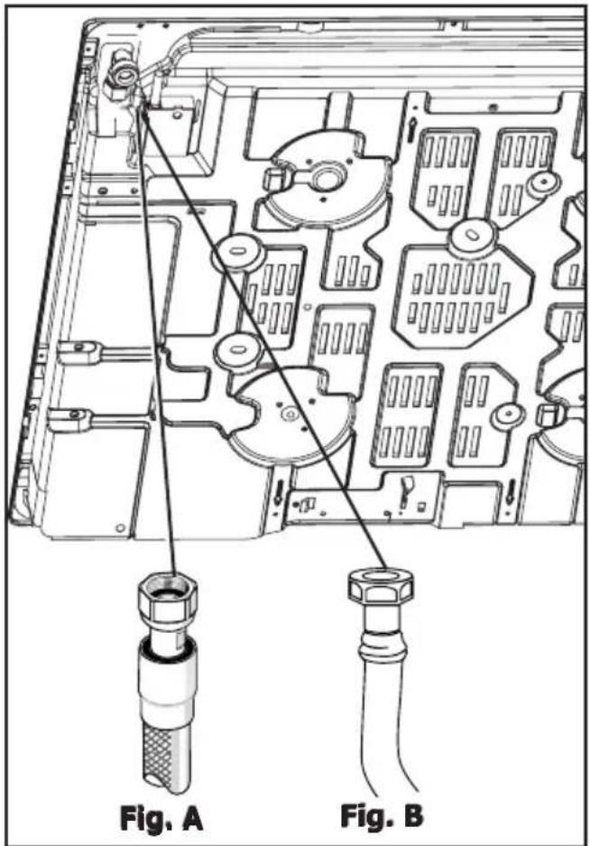
For your safety, you must choose from the three following connection options:
— Connection with a rigid pipe made from copper and with screw-on mechanical connectors (G1/2 gas standard mark). Make the connection directly to the end of the elbow fitted on the appliance.
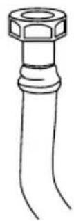
— Connection with a flexible metal hose (stainless steel) with screw-on mechanical connectors (compliant with NF D 36-121 standard) whose service life is unlimited (Fig. A).
— Connection with a flexible rubber hose reinforced with screw-on mechanical connectors (compliant with the NF D 36-103 standard) whose service life is 10 years (Fig. B).

WARNING
When connecting your hob's gas supply, if you have to change the direction of the elbow fitted on the appliance :
- Change the gasket. Screw on the elbow's nut, careful not to exceed a torque of 17 N.m.
• Gas supplied by cylinder or tank (gas butane/propane)
For your safety, you must choose from the three following connection options:
— Connection with a rigid pipe made from copper and with screw-on mechanical connectors (G1/2 gas standard mark). Make the connection directly to the end of the elbow fitted on the appliance.
— Connection with a flexible metal hose (stainless steel) with screw-on mechanical connectors (compliant with NF D 36-125 standard) whose service life is unlimited (Fig. 01).
— Connection with a flexible rubber hose reinforced with screw-on mechanical connectors (compliant with the XP D 36-112 standard) whose service life is 10 years (Fig. 02).


You can obtain the adaptor and the sealing washer from your After-Sales Service.

Screw on the adaptor with a torque not exceeding 25 N.m.
Warning
All soft pipes and hoses whose service life is limited must have a maximum length of two meters and must be accessible along their entire length. They must be replaced before the end of their service life (indicated on the pipe). Regardless of the means of connection chosen, ensure that the connection is sealed, after installation, with soapy water.
In France, you must use a hose or a pipe bearing the stamp NF Gaz

A Sealing washer (not supplied)
B Adaptor (not supplied)
C Clamp (not supplied)
• CHANGING THE GAS SUPPLY
Warning
Your appliance is sold pre-set for natural gas.
The injectors required for adaption to butane/propane can be found in the plastic bag containing this guide.
Each time you change the gas supply, you must complete the following:
— Adapt the gas connection
— Change the injectors
— Adjust the hob connections
- Adapt the gas connection : Refer to the "gas connection section.
- Change the injectors, proceeding as follows:
— Remove the pan supports, heads and covers from all burners.
— Using the wrench provided, unscrew the injectors located under each crucible and remove them (Fig. 01).
— Replace with the corresponding gas injectors, in compliance with the placement of the injectors and the table of gas properties at the end of this section; to do so:
— First screw them in manually until the injector locks into place.
— Apply the wrench to the injector as far as it will go.
— Draw a line on the burner plate using a pencil at the place indicated (Fig. 02).
— Turn the wrench clockwise until the line appears on the other side(Fig. 03).
Warning
Exceeding this limit may damage the product.
— Reposition the burner heads, burner covers and pan supports on the hob.
TIP
Each time you change the gas supply, tick the box corresponding to the new gas level on the label found in the plastic bag. Refer to the corresponding "Gas Connection" section.
Wrench
Fig. 01
Crucible
Injector
Line
Wrench
Fig. 02
Line
Wrench
Fig. 03
- Adjust the hob connections: they are located underneath the knobs (Fig. 04).
— Proceed one tap at a time.
— Remove the knobs and the gaskets by pulling them up.
- SWITCHING FROM NATURAL GAS TO BUTANE/PROPANE
- With a small flat-head screwdriver, screw in all the way the brass (yellow) burner power screws (Fig. 05), in a clockwise direction.
- Replace the gaskets and the knobs, paying careful attention to their direction and ensuring that the knobs are pushed in all the way.
- SWITCHING FROM BUTANE/PROPANE TO NATURAL GAS
- Unscrew the brass (yellow) burner power screws (Fig. 05), using a small flat-head screwdriver, by turning two times counterclockwise.
- Replace the knob,
- Light the burner in maximum heat mode, then turn down to reduced heat mode.
- Remove the knob again, then turn the burner power screws clockwise until it reaches the lowest possible setting that does not extinguish the flame.
- Replace the gasket and knob.
- Make several attempts to shift from the maximum flow rate to the minimum: the flame should not go out; if it does, unscrew the burner power screw so as to obtain good flame retention during these position switches.
Knob
Gasket
Tap
Tap axis
Fig. 05
Burner power adjustment screw
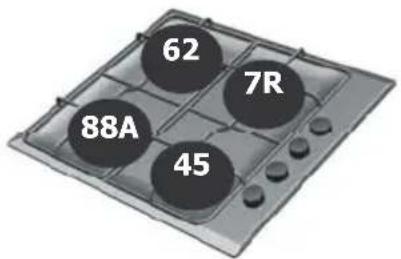
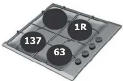
- Marking on the injectors
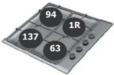
The adjacent table shows where the injectors are positioned on your appliance according to the type of gas used. Each number is marked on the injector.
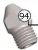
Example: Injector marking 94
Four-burner gas model \*
Natural gas
Butane/Propane gas
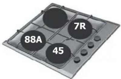
Three-burner gas model\* + 1 electric plate
Natural gas
Butane/Propane gas
* See "Description of the Top" chapter.
- Gas properties
| FR-GBR-GB | FR-GBR-GB | GBR-GBR-GB | GBR-GB | ||
| Appliance intended to be installed in: | Butane | Propane | Natural Gas Gas | Natural | |
| FR......cat : II2E+3+ G30 G31 G20 G25 GB ......cat : II2H3+At 15°C under 1013 mbars | 28-30mbar | 37mbar 20 mbar | 25 mbar | Hourly rate below: | |
| HIGH-SPEED BURNER | |||||
| Marking engraved on injectorNominal heat release rate (kW) | 7R 7R 1R 1R2,25 2,25 | 2,35 2,35 | |||
| Hourly rate (g/h)Hourly rate (l/h) | 164 | 161 | 224 | 260 | |
| SUPER FAST BURNER | |||||
| Marking engraved on injectorNominal heat release rate (kW) | 88A 88A | 137 1373,20 | 3,05 3,05 | ||
| Hourly rate (g/h)Hourly rate (l/h) | 233 | 229 | 290 | 338 | |
| SEMI-FAST BURNER | |||||
| Marking engraved on injectorNominal heat release rate (kW) | 62 | 62 | 94 | 94 | |
| Hourly rate (g/h)Hourly rate (l/h) | 1,50 1,50 | 1,50 1,50 | |||
| AUXILIARY BURNER | |||||
| Marking engraved on injectorNominal heat release rate (kW) | 45 | 45 | 63 | 63 | |
| Hourly rate (g/h)Hourly rate (l/h) | 0,70 0,70 | 0,85 0,85 | |||
| 60 CM HOB FOUR GAS BURNERS WITH SUPER FAST | |||||
| Total heat release rate (kW)Maximum flow rate (g/h)(l/h) | 7,65 7,65 | 7,75 7,75 | |||
| 557 | 547 | 738 | 858 | ||
| 60 CM THREE BURNERS + 1500 W ELECTRIC PLATE | |||||
| Total heat release rate (kW)Maximum flow rate (g/h)(l/h) | 6,15 6,15 | 6,25 6,25 | |||
| 448 | 440 | 595 | 692 | ||
• DESCRIPTION OF THE TOP
BPE6411*M BPE6410*
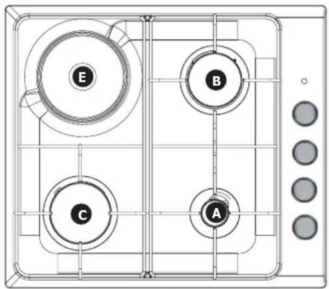
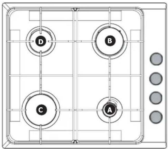
A Auxiliary burner 0.85 kW (*)
B High-speed burner 2.25 kW (*)
Super fast burner 3.05 kW (*)
D Semi-fast burner 1.50 kW (*)
Electric plate 1.50 kW - diameter 145 mm
(*) Power obtained with natural gas G20.
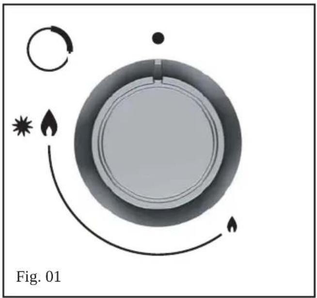
• LIGHTING THE HOB
Each burner is supplied by a tap which can be opened by pressing it and turning it in in a counterclockwise motion.
The “●” point corresponds to closing the tap.
Choose the desired burner by using the symbols located near the knobs (e.g.: Rear right burner)
To light a burner, press the electronic starter button by turning the knob to the maximum position
Keep pressing the starter button until the burner ignites.
The setting for more moderate flame intensities is between the and the symbol
natural_image
Diagram of a circular mechanical component with directional arrows and star symbol, labeled Fig. 01 (no text or symbols on diagram itself)
TIP
— If the flame goes out accidentally, reignite normally following the lighting instructions.
— The burner's flames are smaller near the support to protect the support's enamel. — The noise made by certain burners is related to their high power and to gas combustion; it does not alter cooking quality.
— In the event of a power cut, place a lighted match near an open burner.
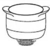
- Which burner should you use depending on your cookware?
| Diameter of the cookware | Burner | Use |
| 18 to 28 cm | Super fast | Frying - Boiling |
| 16 to 28 cm | High-speed | Searing foods |
| 12 to 24 cm | Semi-fast | Sauces - Reheating |
| Auxiliary | Gentle simmer |

WARNING
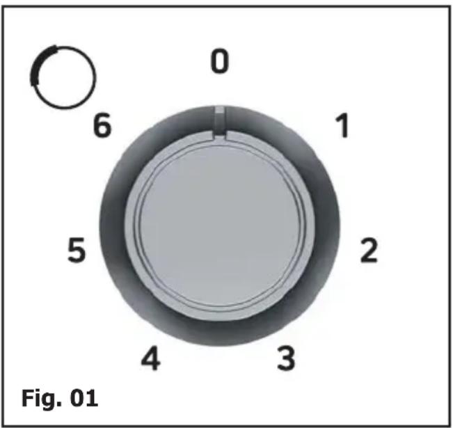
— Adjust the ring of flames so that they do not extend beyond the edges of the cookware (Fig. 01).
— Do not use cookware with a concave or convex bottom (Fig. 02).
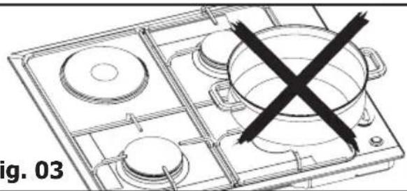
— Do not use cookware that partially covers the knobs (Fig. 03).
— Do not leave a gas burner operating with empty cookware.

Tip
Keep natural ventilation outlets in your home open or install a mechanical ventilation device (mechanical ventilation hood).
Intensive, prolonged use of the appliance may require additional ventilation; you can, for example, open a window or provide more effective ventilation or increase power to the mechanical ventilation, if you have it (a minimum air flow of 2 m^3 per kW of gas power is required).
Example: 60 cm - Four gas burners
Total power: 1.5 + 2.25 + 3.1 + 0.85 =
7.7 kW
7.7 kW × 2 = 15.4 m³/h
minimum flow.
GOOD

BAD
Fig. 01
CONVEX
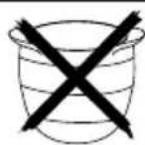
CONCAVE
Fig. 02
natural_image
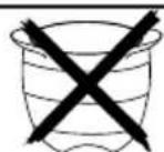
Line drawing of a cooking pan with a crossed-out pot and circular pots (no text or symbols)- MOST SUITABLE COOKWARE FOR THE ELECTRIC PLATE (depending on model)
Use cookware with flat bottoms that perfectly hug the surface of the burner:
– in stainless steel with a thick, tri metal or "sandwich" bottom",
– in aluminium with a thick (smooth) bottom,
– in enamelled steel.
• POWERING ON THE ELECTRIC PLATE (depending on the model)
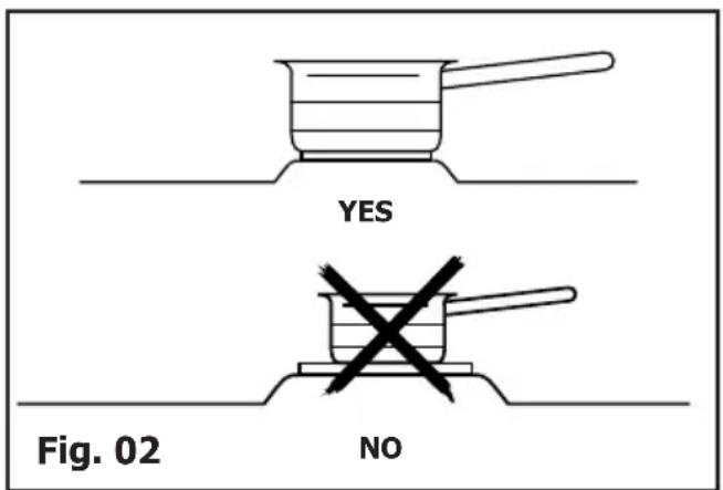
Position the knob on the marking that corresponds to the desired cooking method (Fig. 01) (see cooking guide at the end of this guide). The cooking zone's power indicator lights up.
Upon first use, allow the plate to heat up with no cookware at maximum power for three minutes to harden the coating.

TIP
— Use cookware of an appropriate size: the diameter of the bottom should be greater than or equal to the diameter of the electric cooking zone (Fig. 02).
— When cooking is nearly complete, turn the knob to the "O" off position to take advantage of the heat accumulated in the plate.
— Use a lid on your cookware as often as possible to reduce the loss of heat by evaporation.

WARNING
— Do not operate an electric cooking zone without cookware (except during initial use) or with an empty pot.
— The electric plate will remain hot for a certain time after the knob has been turned to the "O" position. Do not touch this zone because there is a risk of burning.
• MAINTAINING YOUR APPLIANCE
| MAINTENANCE... | WHAT TO DO ? | PRODUITS/ACCESSOIRES A UTILISER |
| Of the spark plugs and injectors | If the spark igniters become dirty, clean them using a small, stiff-bristled brush (non-metallic).The gas injector is located in the centre of the burner in the form of a crucible. Be careful not to clog it during cleaning, as this will reduce the performance of your hob. In the event of obstruction, use a safety pin to unclog the injector. | . Small, hard-bristled brush.. Safety pin |
| Of the pan supports and gas burners | If tough stains occur, use a non-abra-sive cream, then rinse with clean water. Carefully wipe each part of the burner before using your hob again. | . Gentle scrubbing cream.. Cleaning sponge |
| Of the electric plate | The heating plate is protected by a black coating, so you should avoid using any abrasive products. After each use, wipe it with a thick towel.If the plate shows signs of rusting, remove the rust (with an emery cloth, for example) and restore the black coating with a commercially available high-temperature restorative product. | . Commercially available restorative product. |
| Enamel or stainless steel | To clean the hob's enamel, use a scour-ing cream. Polish it with a dry cloth. Do not allow acidic liquids such as lemon juice, vinegar, etc. to remain in contact with the enamel.To clean the hob's stainless steel, use a sponge and soapy water or a commercially available special stainless steel product. | . Gentle scrubbing cream.. Commercially available specialised stainless steel product. |

Warning
It will be easier to maintain your hob if you clean it before it has completely cooled down. However, never clean your appliance while it is in operation. Set all the electric and gas controls to zero.

Tip
— It is better to clean the parts of the hob by hand rather than in the dishwasher.
— Do not use an abrasive sponge to clean your hob.
— Do not use steam cleaning.
• DURING USE
| YOU OBSERVE THAT : WHAT | SHOULD YOU DO? |
| ·Lighting of burners:There are no sparks when you press the knobs. | . Check the electrical connection of your appliance. Check that the spark plugs are clean.. Check that the burners are clean and properly assembled. If the hob is attached to the work surface, check that the mounting brackets are not deformed. Check that the gaskets under the knobs are not coming out of their seats.C'est normal. |
| ·When you press on a knob, all the burners spark at the same time. | . This is normal. The lighting function is centralised and controls all of the burners simultaneously. |
| ·There are sparks, but the burner (burners) does (do) not light. | . Check that the gas inlet pipe is not pinched.. Check that the length of the gas inlet pipe is less than two meters.. Check that the gas inlet pipe is open.. If you have gas in a cylinder or tank, check that it is not empty.. If you have just installed the hob or changed the gas cylinder, hold the knob down in maximum open position until gas arrives in the burners. Check that the injector is not clogged; if it is, unclog it with a safety pin. Light your burner before placing your saucepan on it. |
| ·In reduced heat mode, the burner goes out or the flames remain high. | . Avoid strong air currents in the room.. Check that the gas type being used corresponds to the injectors installed (Read about markings on the injectors in the "Changing the Gas Supply" chapter).Reminder: The cooking hobs are sold pre-set for use with gas from the grid (natural gas). Check that the burner power screws are properly set (See the "Changing the Gas Supply" chapter). |
| ·The flames look irregular or uneven. | . Check the cleanliness of the burners and injectors under the burners, the assembly of the burners, etc. Check that there is enough gas in the bottle. |
| ·During cooking, the knobs become hot. | . Use small saucepans on the burners located closest to the knobs. Large cookware should be used on the largest burners, which are farther away from knobs. Properly place the saucepan in the centre of the burner. |
• GAS COOKING GUIDE
| PREPARATIONS | TIMES | SUPER FAST | FAST | SEMI FAST | AUXILIAIRY | |
| SOUPS Broths | 8-10 minutes | X | ||||
| Thick soups | X | |||||
| FISH | Court-bouillon | 8-10 minutes | X | |||
| Grilled food | 8-10 minutes | X | ||||
| SAUCES | Hollandaise, béarnaise | 10 minutes | X | X | ||
| Béchamel, aurore | X | X | ||||
| VEGETABLES | Chicory, spinach | 25-30 minutes | X | |||
| Cooked peas | X | X | ||||
| Provençal tomatoes 15-20 | minutes | X | X | |||
| Browned potatoes | X | X | ||||
| Pasta | X | |||||
| MEATS Steak | Blanquette, Osso-bucco | 90 minutes | X | |||
| Sauteed poultry breasts | 10-12 minutes | X | ||||
| Tournedos | 10 minutes | X | ||||
| FRITURE | Chips | X | ||||
| Fritters | X | |||||
| DESSERTS | Rice pudding | 25 minutes | X | X | ||
| Fruit compote | X | X | ||||
| Crêpes | 3-4 minutes | X | X | |||
| Chocolate | 3-4 minutes | X | ||||
| Custard | 10 minutes | X | ||||
| Coffee (small percolator) | X |
• ELECTRIC COOKING GUIDE
| PREPARATIONS VERY HIGH | HIGH MEDIUM GENTLE | KEEP | SIMMER WARM | |||
| 6 | 5 | 3 | - | 4 | ||
| SOUPS Broths XXThick soups X XFISH Court-bouillon XXFrozen X XSAUCES Thicks Xwith butter | ||||||
| VEGETABLES | Chicory, spinachDry vegetablesBoiled potatoesBrowned potatoes | XXX | XX | |||
| MEATS SteakGrilled food | XX | |||||
| FRYING Chips | X | |||||
| MISCEL-LANEOUS | Fruit compotesPancakesCustardMelted chocolateJamsMilkPastaRice puddingKeep warm | XX | XX | XX | ||
• SERVICE CALLS
Any maintenance on your equipment should be undertaken by:
- either your dealer,
- or another qualified mechanic who is an authorized agent for the brand appliances.
When making an appointment, state the full reference of your equipment (model, type and serial number). This information appears on the manufacturer's nameplate attached to your equipment. (Fig. 01).
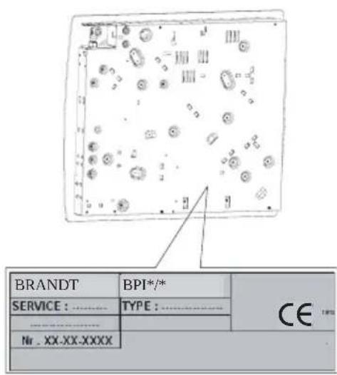
Fig. 01
Brandt
natural_image
Black-and-white photo of a bowl with leaf garnish, surrounded by bowls of tea leaves (no text or symbols visible)natural_image
3D rendering of a four-gas stove with four panes and control buttons (no text or symbols)Estimado cliente:
natural_image
Line drawing of a gas stove burner with six ovens (no text or symbols)Fig. 01
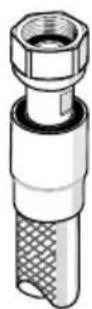
Fig. 02
Cambio de gas

Atención
natural_image
Diagram of a circular mechanical component with directional arrows and star symbol, labeled Fig. 01 (no text or symbols on the diagram itself)
Consejo
natural_image
Line drawing of a four-tiered gas stove with a crossed-out valve (no text or symbols)natural_image
Black-and-white photo of a bowl with leaf garnish, blurred bowls in background (no text or symbols)natural_image
Line drawing of a gas stove with a crossed-out electrical symbol (no text or labels)حداري:


- Brandt
- Conseils
- INSTALLING YOUR APPLIANCE
- USING YOUR APPLIANCE
- DAILY CARE OF YOUR APPLIANCE
- SPECIAL MESSAGES, INCIDENTS
- COOKING GUIDES
- AFTER-SALES SERVICE
- IMPORTANT SAFETY INSTRUCTIONS - READ CAREFUL-LY AND RETAIN FOR FUTURE USE.
- This user guide is available for download on the brand's website.
- WARNING:
- • DESCRIPTION OF THE HOB
- - FLUSH MOUNTING
- • TIPS FOR FLUSH MOUNTING
- • ELECTRICAL CONNECTION
- Attention
- • GAS CONNECTION
- • Preliminary comments
- • Gas distributed by pipe; natural gas,
- WARNING
- • Gas supplied by cylinder or tank (gas butane/propane)
- • CHANGING THE GAS SUPPLY
- TIP
- - SWITCHING FROM NATURAL GAS TO BUTANE/PROPANE
- - SWITCHING FROM BUTANE/PROPANE TO NATURAL GAS
- - Marking on the injectors
- Four-burner gas model \*
- Three-burner gas model\* + 1 electric plate
- - Gas properties
- • DESCRIPTION OF THE TOP
- • LIGHTING THE HOB
- - MOST SUITABLE COOKWARE FOR THE ELECTRIC PLATE (depending on model)
- • POWERING ON THE ELECTRIC PLATE (depending on the model)
- • MAINTAINING YOUR APPLIANCE
- • DURING USE
- • SERVICE CALLS
- Cambio de gas
- Atención
- Consejo
Brand : BRANDT
Model : BPE6410X
Category : Cooker