P-300 - Basket Pando - Free user manual and instructions
Find the device manual for free P-300 Pando in PDF.

User questions about P-300 Pando
0 question about this device. Answer the ones you know or ask your own.
Ask a new question about this device
Download the instructions for your Basket in PDF format for free! Find your manual P-300 - Pando and take your electronic device back in hand. On this page are published all the documents necessary for the use of your device. P-300 by Pando.
USER MANUAL P-300 Pando
natural_image
Technical line drawings of four different mechanical components with circular cutouts (no text or symbols)Pando
integralcooking
MOTOR EXTERIOR
V.1550 N ECO
V.2450 N ECO
V.2600 ECO
V.3000 N ECO

(*) This manual is generic for various models and versions, the use of the certification and mark is only for those whose identification label has indicated the symbol.

text_image
COLLECTION OF APLIANCESThe symbol on the product or its packaging indicates that this product cannot be disposed of like normal domestic waste. The product must be handed over at a collection point for recycling electrical and electronic equipment. If you ensure that this product is correctly disposed of, you will help to avoid the possible negative environmental and public health effects that could arise from incorrect disposal. For more detailed information about recycling this product, please contact your city authorities, the domestic waste service or the establishment where you purchased it. This electrical appliance is marked in compliance with European Directive 2012/19/EU on electrical and electronic appliance waste (WEEE).

ENVIRONMENTAL PROTECTION AND WASTE TREATMENT
DISPOSAL OF THE PACKAGING. The packaging is marked with in Green Dot.
In its commitment to the protection of the environment and in compliance with the provisions of the European Directive 94/62 / EC on packaging and packaging waste and the derived Law 22/2011 on Contaminated Residues and Soils, Pando entrusts entities of social economy an Integrated Management System, responsible for the periodic collection at the consumer's home or in its vicinity of used packaging and packaging waste for subsequent treatment.
To remove all packaging materials such as cardboard, expanded polyurethane, and film, use the appropriate containers.
This ensures the correct treatment and reuse of packaging materials.
The manufacturer will not be held liable for any possible inaccuracies due to printing or transcription errors in this manual. The manufacturer reserves the right to incorporate modifications considered useful or necessary into the products, which will not alter their essential functional and safety characteristics.
Please read these safety and installation instructions before using the motor.
Motors should only be used when connected to the hood. If there is a risk of water reaching the motor through the conduits it will be necessary to provide exterior protection.
External motors are not waterproof; they are not apt for installing exposed to the elements without special protection.
Once installed, make sure that no moving parts are accessible. Roof motors should not be used in dangerous environments and not be directly connected to active chimneys (wood burning, etc.).
WARNING! Before usage or any maintenance operations are carried out, make sure the power is disconnected, (cut-off switch or differential) and make sure the impeller is completely stationary.
WARNING! Motor fans have blades with sharp edges that can cause injury.
WARNING! Take care when opening the access cover for maintenance of the boxes, as fans with the motor installed on the cover are relatively heavy.
EN – TRANSPORT AND STORAGE
All Pando roof motors are packaged for normal handling during transport. When handling, use adequate elevation equipment to avoid damaging the motor and injuring personnel.
WARNING! Do not lift the fans by their cable, the connection box, the impeller or the suction cone.
Avoid impact and shaking of the equipment. Store the motors in a dry place and protected from the elements until final installation.
EN - INSTALLATION
An installation manual with illustrations and explanations is included.
The motor must always be connected to an extractor hood, never directly to the mains.
Bear in mind the safety information given above. Installation, electrical connection and start-up should only be carried out by authorised/specialised personnel.
The motor must be installed in such a manner that its vibrations are not transmitted to the conduits or structures of the building. Make sure the motor is firmly and stably secure and that it is level.
WARNING! This motor must not be installed upside down. The fan should be installed in such a manner that maintenance and repair operations can be carried out simply and safely. Noise disturbance can be avoided by installing a silencer (Not included, but available).
EN - INSTALLATION
V1550 N ECO:
- Should be installed with a ∅150mm conduit, a different diameter will affect the performance of the motor, reducing its suction capacity, increasing noise produced as well as causing other problems.
- The recommended length of the conduit between the hood and the motor is 4 - 6 m maximum, a greater distance will reduce the motor's suction capacity, while a shorter distance will increase the noise of the hood, if the latter case in inevitable, we recommend the use of soundproofing elements.
- It is recommended that the conduit from the hood to the motor is without sharp angles, as they will reduce the suction capacity of the motor. If they are inevitable, try to ensure they are not too close to the inlet or outlet of the motor (at least 0.5m away). Do not use elbow joints of less than 90°, or place one after another, the minimum recommended distance between them is 1m, and try to make them as open as possible.
- The maximum total length of the conduit from the hood to the exterior should be 12 linear metres, not counting elbow joints (one elbow joint is equivalent to 2.5 linear metres), any longer and the suction capacity of the motor will be reduced.
V2450 N ECO:
- Should be installed with a ∅200mm conduit, a different diameter will affect the performance of the motor, reducing its suction capacity, increasing noise produced as well as causing other problems.
- The recommended length of the conduit between the hood and the motor is 4.6 m maximum, a greater distance will reduce the motor's suction capacity, while a shorter distance will increase the noise of the hood, if the latter case in inevitable, we recommend the use of soundproofing elements.
- It is recommended that the conduit from the hood to the motor is without sharp angles, as they will reduce the suction capacity of the motor. If they are inevitable, try to ensure they are not too close to the inlet or outlet of the motor (at least 0.5m away). Do not use elbow joints of less than 90°, or place one after another, the minimum recommended distance between them is 1m, and try to make them as open as possible.
- The maximum total length of the conduit from the hood to the exterior should be 1–2 linear metres, not counting elbow joints (one elbow joint is equivalent to 2.5 linear metres), any longer and the suction capacity of the motor will be reduced.
V2600 ECO:
- Should be installed with a ∅200mm conduit, a different diameter will affect the performance of the motor, reducing its suction capacity, increasing noise produced as well as causing other problems.
- The recommended length of the conduit between the hood and the motor is 6-8 m maximum, a greater distance will reduce the motor's suction capacity, while a shorter distance will increase the noise of the hood, if the latter case in inevitable, we recommend the use of soundproofing elements.
- It is recommended that the conduit from the hood to the motor is without sharp angles, as they will reduce the suction capacity of the motor. If they are inevitable, try to ensure they are not too close to the inlet or outlet of the motor (at least 0.5m away). Do not use elbow joints of less than 90°, or place one after another, the minimum recommended distance between them is 1m, and try to make them as open as possible.
- The maximum total length of the conduit from the hood to the exterior should be 1–2 linear metres, not counting elbow joints (one elbow joint is equivalent to 2.5 linear metres), any longer and the suction capacity of the motor will be reduced.
EN - INSTALLATION
V3000 N ECO:
- Should be installed with a ∅200mm conduit, a different diameter will affect the performance of the motor, reducing its suction capacity, increasing noise produced as well as causing other problems.
- The recommended length of the conduit between the hood and the motor is 6-8 m maximum, a greater distance will reduce the motor's suction capacity, while a shorter distance will increase the noise of the hood, if the latter case in inevitable, we recommend the use of soundproofing elements.
- It is recommended that the conduit from the hood to the motor is without sharp angles, as they will reduce the suction capacity of the motor. If they are inevitable, try to ensure they are not too close to the inlet or outlet of the motor (at least 0.5m away). Do not use elbow joints of less than 90°, or place one after another, the minimum recommended distance between them is 1m, and try to make them as open as possible.
- The maximum total length of the conduit from the hood to the exterior should be 12 linear metres, not counting elbow joints (one elbow joint is equivalent to 2.5 linear metres), any longer and the suction capacity of the motor will be reduced.
EN - INSTALLATION
WARNING! Please read this user's manual carefully before installing the motor.
Before installing, check that the diameters of the fume outlet correspond to those indicated in the specifications table.
Do not manipulate the internal connections in the motor box. Do not plug the motor directly into the mains socket, it should always be connected through the hood, following the connection instructions.
Your model may differ from the models described here, to see the characteristics of your specific model please refer to the exterior motor data sheet.

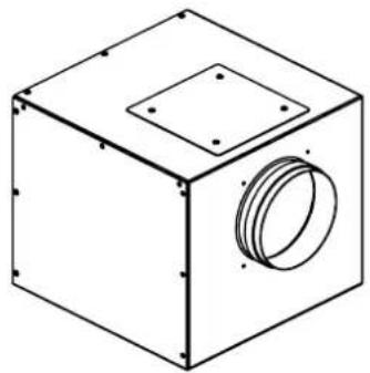
VERY IMPORTANT! An opening must be provided to access the motor for maintenance and possible repairs by the technical assistance service.

text_image
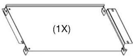
Cover to access motor(1X)
V1550 N ECO
natural_image
Isometric line drawing of a cube with a circular opening and two square holes (no text or symbols)V2600 ECO

natural_image
Technical line drawing of a mechanical component with a conical top and circular side (no text or symbols)V2450 N ECO
V3000 N ECO

natural_image
Isometric line drawing of a rectangular box with two circular recesses and mounting holes (no text or symbols)
natural_image
Isometric line drawing of a box with an arrow indicating rotation (no text or symbols)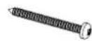
(4X) DIN7981 4.8x50

(4X) M8
natural_image
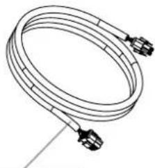
Line drawing of a coiled cable or hose with connectors (no text or symbols)6m - V1550
6m - V2450
12m - V2600
12m - V3000
V1550 N ECO / V2600 ECO
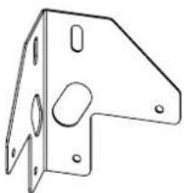
natural_image
Technical line drawing of a mechanical bracket with mounting holes and a central oval feature (no text or symbols)(4X)

(16X) DIN7504N 4.8x16
50 N ECO / V3000 N ECO
text_image
(1X)
(12X) DIN7985 M5x10
HERRAMIENTAS NECESARIAS / FERRAMENTAS NECESSÁRIAS / LES OUTILS NÉCESSAIRES / TOOLS NEEDLE

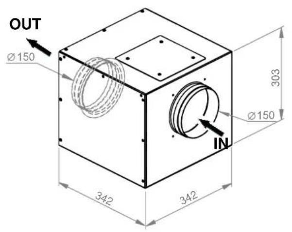
V.1550 N ECO Tipo / Type 1
text_image
OUT Ø150 342 342 303 Ø150 INV.1 550 N ECO Tipo / Type 2

text_image
IN OUT Ø150 Ø150 303 342 342MEDIDAS MÀXIMAS CON SOPORTES
MEDIÇÕES MÁXIMAS COM SUPORTES DIMENSIONS MAXIMALES AVEC SUPPORTS MAXIMUM MEASURES WITH SUPPORTS

text_image
426 342 303 386 342 426V.2450 N ECO Tipo / Type 2
V.3000 N ECO Tipo / Type 2
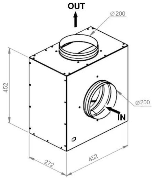
text_image
OUT Ø200 452 Ø200 IN 272 452MEDIDAS MÀXIMAS CON SOPORTES
MEDIÇÕES MÁXIMAS COM SUPORTES DIMENSIONS MAXIMALES AVEC SUPPORTS MAXIMUM MEASURES WITH SUPPORTS
text_image
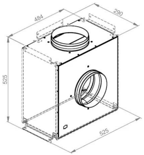
484 290 525 525V 2600 ECO Tipo / Type 1

text_image
OUT Ø 200 603 267 292 292 Ø 200 371 485 INV.2600 ECO Tipo / Type 2

text_image
OUT Ø 200 559 267 292 371 485 Ø200 INMEDIDAS MÀXIMAS CON SOPORTES
MEDIÇÕES MÁXIMAS COM SUPORTES
DIMENSIONS MAXIMALES AVEC SUPPORTS
MAXIMUM MEASURES WITH SUPPORTS
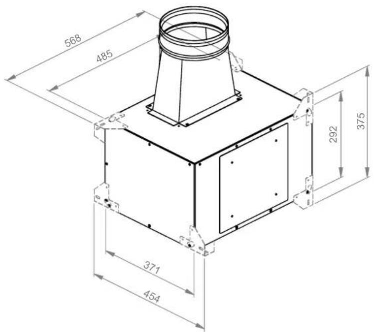
text_image
568 485 292 375 371 454Before installing choose the position of flue pipe (Type 1 / Type 2).
1

natural_image
Technical diagram of a mechanical assembly with labeled components and directional arrows (no text or symbols)2

natural_image
Technical line drawing of a mechanical assembly with circular components and directional arrows indicating motion (no text or symbols)text_image
Technical diagram illustrating a mechanical assembly with labeled components and directional arrows indicating motion or movement.4
natural_image
Technical diagram of a mechanical assembly with internal components and directional arrows (no text or labels)Before installing choose the position of flue pipe (Type 1 / Type 2).
1

natural_image
Technical line drawing of a mechanical assembly with no visible text or symbols2

natural_image
Technical diagram of a mechanical device with internal components and directional arrows indicating motion (no text or symbols)natural_image
Technical line drawing of a mechanical assembly with internal components and directional arrows (no text or symbols)4
natural_image
Technical line drawing of a mechanical device with internal components and directional arrows indicating motion (no text or symbols)INSTALACIÓN / INSTALAÇÃO / INSTALLATION / INSTALLATION
1
EN- Unpack the motor. Check that the model corresponds to what you have ordered (See the motor specification sheet) and that it is undamaged.
2
EN- Make sure that the dimensions of the box coincide with the dimensions of the false ceiling and existing conduits. Check that the place where it is to be installed is accessible and safe for technical servicing.
3
EN- Ensure that you know which of the openings is the inlet and which is the outlet, see the model and type on the table on page 16. You must connect the inlet tube to the hood and the outlet to the conduit that leads outside. This is indicated by labels on the legs: Inlet -IN-connect to the hood and outlet -OUT-connect to the conduit leading outside.
INSTALACIÓN / INSTALAÇÃO / INSTALLATION / INSTALLATION
④ V1550 N ECO / V2600 ECO
EN-Chose the face of the box on which you wish to attach the motor. Fit the 4 an angle brackets onto the box.

INSTALACIÓN / INSTALAÇÃO / INSTALLATION / INSTALLATION

V2450 N ECO / V3000 N ECO
EN – Chose the face of the box on which you wish to attach the motor. Place the fastening piece onto the box.

natural_image
Technical line drawing of a mechanical housing assembly with directional arrows indicating movement (no text or symbols)INSTALACIÓN / INSTALAÇÃO / INSTALLATION / INSTALLATION
5
EN Fit the self tapping screws that will secure the angles to the box.
V1550 N ECO / V2600 ECO

text_image
Technical diagram showing a mechanical assembly with labeled components and a 16X rotational motion indicator.V2450 N ECO / V3000 N ECO

text_image
(4X)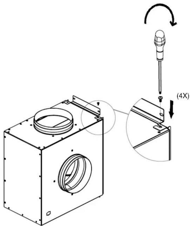
text_image
Technical diagram showing a mechanical assembly with a 4X magnified view of the component being inserted into a screwdriver.INSTALACIÓN / INSTALAÇÃO / INSTALLATION / INSTALLATION
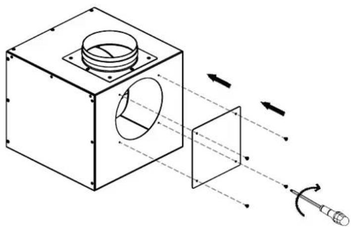
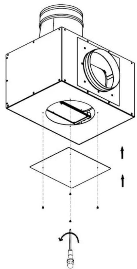
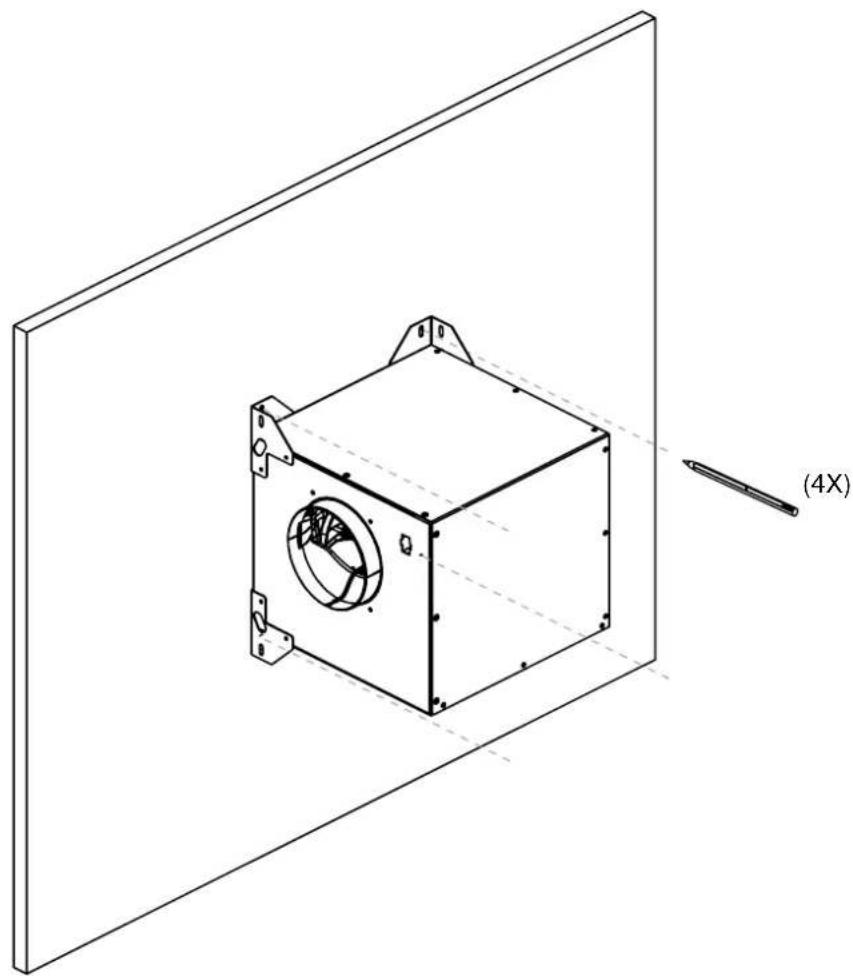
6
EN-Place the box in the chosen location and secure it to the wall or ceiling with the screws. To avoid vibration you can fit rubber bushing washers between the wall and the box (not included).
natural_image
Isometric line drawing of a mechanical component with a circular opening and mounting bracket, shown against a plain background (no text or symbols)INSTALACIÓN / INSTALAÇÃO / INSTALLATION / INSTALLATION
POSICIÓN SOPORTES
text_image
Technical diagram showing a 3D mechanical component with a 4X rotation indicator and a screwdriver, illustrating assembly or motion.7
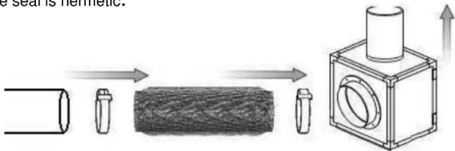
EN- Connect the motor to the outlet and the hood following the advice given in the user manual. Secure the connections with ties or aluminium tape (Not included), so as to ensure the seal is hermetic.
text_image
e scar is hermetic.
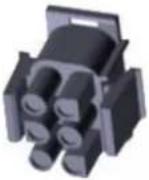
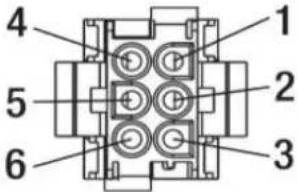
The engine has an electrical connection via a 6-core female connector, which is recessed on one side of the engine body. In the hood near the hood exhaust duct ring, there is another equal connector (6-core pins). Before connecting engine and hood, make sure that the hood is disconnected from the power supply. Supplied a connection cable between engine and hood with 6-core male connectors at their ends, make this connection and make sure you have connected firm and secure. The interconnection cable between engine and hood must be protected against external damage and must not be tampered with, cut or spliced. Any manipulation of the cable or connections improper or unauthorized by Pando may cause serious damage to the engine or hood that would not be covered by the manufacturer's warranty.
INSTALACIÓN / INSTALAÇÃO / INSTALLATION / INSTALLATION

natural_image
Technical illustration of a mechanical assembly with pipe connection and component disassembly, showing internal components and motion directions (no text or symbols)INSTALACIÓN / INSTALAÇÃO / INSTALLATION / INSTALLATION
ES- ESQUEMA CONEXIONES:
PT- ESQUEMA DE LIGAÇÕES:
FR- SCHÉMA CONNEXIONS:
EN- WIRING DIAGRAM:
| Cable alargo macho a macho 6/12/18m | |||
| Male to male extension wire 6/12/18m | |||
| Macho / Male 6 pins | No PIN CONNECTOR | COLOR CABLE WIRE COLOR | DESCRIPCIÓN DESCRIPTION |
 | 1 | Amarillo/verde Yellow/green | Tierra Ground |
| 2 | Azul Blue | Neutro / Neutral / 220vAC | |
| 3 | Marrón Brown | Fase / Phase / 220vAC | |
 | 4 | Rojo Red | Malla / Mesh |
| 5 | Negro Black | Control PWM / (-) 0-10vDC | |
| 6 | Gris Grey | Control PWM / (+) 0-10vDC | |
PROTECCIÓN OPCIONAL / PROTEÇÃO OPCIONAL / PROTECTION OPTIONNELLE / OPTIONAL PROTECTION

text_image
Ø40ATENCIÓN / ATENÇÃO / ATENTTION / ATENTION
ES- CONEXIONES:
Do not disconnect from the motor boxes or cut or make any connections not authorised by themanufacturer,any of these actions will automatically void the guarantee.

text_image
Diagram illustrating a disassembled electrical plug with no visible text, including a crossed-out screwdriver and a prohibition symbol.ES - MANENIMIENTO
-Electrical power is disconnected (Circuit breaker or differential).
-Fan blades are completely stationary.
-Follow personal safety regulations!
Inadequate maintenance of the hood filter systems (See hood user manual) can result in an excessive accumulation of grease on the motor blades, putting them out of balance and causing malfunction or abnormal noises.
The motor blades are maintenance-free and, if necessary, should only be repaired by specialised and authorised personnel. Do not clean with a pressure jet cleaning system.
Make sure that any balance weights are not displaced and that the blades are not
deformed. In case of motor malfunction, contact the Pando official technical service.
Technical assistance service: 902 41 55 10
Fax. 93 757 96 53 / E-mail: divisiontecnica@pando.es
| ESPAÑA, PORTUGAL Y ANDORRA: | OTROS PAÍSES: | ||
| ESwww.pando.es/asistencia-tecnica/ |  | ENhttps://www.pando.es/en/after-sales-services/FRhttps://www.pando.es/fr/service-apres-vente/ |  |
VERY IMPORTANT: The motor must remain accessible for maintenance or possible repairs to be carried out by the Technical Assistance Service. Access to the motor for maintenance or repair must be safe and non-hazardous for the Technicians. If access and disassembly are seen to pose a risk for personnel, Pando reserves the right to refuse to repair the equipment until the conditions are appropriate for working. Therefore, to avoid future maintenance problems, we recommend to bear this in mind when making the installation. For further information or clarification, please contact your Distributor or contact directly Pando's Technical Division for Hoods.
NOTAS/NOTAS/REMARQUES/NOTES:
NOTAS/NOTAS/REMARQUES/NOTES:
INOXPAN S.L.
Pol. Ind. El Cros
text_image
QR code with a hammer and sickle symbol in the center, likely linking to a service or application.SERVICIO POST VENTA España, Portugal y Andorra