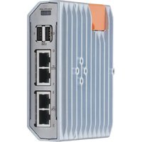
AE2100 - Industrial network gateway IFM - Free user manual and instructions
Find the device manual for free AE2100 IFM in PDF.


User questions about AE2100 IFM
0 question about this device. Answer the ones you know or ask your own.
Ask a new question about this device
Download the instructions for your Industrial network gateway in PDF format for free! Find your manual AE2100 - IFM and take your electronic device back in hand. On this page are published all the documents necessary for the use of your device. AE2100 by IFM.
USER MANUAL AE2100 IFM
Operating instructions
moneo|edge
Gateway
AE2100
Contents
1 Preliminary note 3
1.1 Legal and copyright information 3
1.2 Symbols used 3
1.3 Warnings.... 3
1.4 Applicable documents.... 3
1.5 Change history 4
2 Safety instructions.... 5
2.1 Safety symbol on the device 5
2.2 Cyber security.... 5
3 Intended use.... 7
4 Items supplied.... 8
5 System description 9
5.1 Overview....9
5.2 Ethernet ports 9
5.3 USB ports 10
5.4 Micro SD card slot.... 10
5.5 Status LEDs 10
5.6 Voltage supply 10
5.7 Operating software 10
6 Installation.... 11
6.1 Install device.... 11
7 Electrical connection.... 12
7.1 General notices.... 12
7.2 Ethernet ports 12
7.3 USB ports 12
7.4 Voltage supply 13
8 Operating and display elements 14
8.1 LEDs.... 14
8.1.1 Status 14
8.1.2 Ethernet 14
9 Set-up.... 15
9.1 Getting started 15
10 Troubleshooting 17
10.1 Status LEDs 17
11 Maintenance, repair and disposal 18
11.1 Battery change 18
11.2 Cleaning the housing surface 19
11.3 Repair.... 19
11.4 Disposal 19
11.5 Updating the system software.... 19
1 Preliminary note
You will find instructions, technical data, approvals and further information using the QR code on the unit / packaging or at documentation.ifm.com.
1.1 Legal and copyright information
© All rights reserved by ifm electronic gmbh. No part of these instructions may be reproduced and used without the consent of ifm electronic gmbh.
All product names, pictures, companies or other brands used are the property of the respective rights owners.
1.2 Symbols used
√ Requirement
Instructions
Reaction, result
[...] Designation of keys, buttons or indications
→ Cross-reference

Important note
Non-compliance may result in malfunction or interference.

Information
Supplementary note
1.3 Warnings
Warnings indicate the possibility of personal injury and damage to property. This enables safe product handling. Warnings are graded as follows:

WARNING
Warning of serious personal injury
▷ If the warning is not observed, fatal and serious injuries are possible.

CAUTION
Warning of minor to moderate personal injury
▷ If the warning is not observed, minor to moderate injuries are possible.
ATTENTION
Warning of damage to property
▷ If the warning is not observed, damage to property is possible.
1.4 Applicable documents
- Data sheet
- Quick reference guide
-
Operating instructions (supplement) - Cybersecurity
-
moneo|Appliance Management System (AMS) software manual
- ifm moneo online help
1.5 Change history
| Version | Subject | Date |
| 00 | New document created | 03 / 2024 |
| 01 | • Added: Notes on the cULus scope of validity | 03 / 2025 |
2 Safety instructions
- The unit described is a subcomponent for integration into a system.
- The system architect is responsible for the safety of the system.
-
The system architect undertakes to perform a risk assessment and to create documentation in accordance with legal and normative requirements to be provided to the operator and user of the system. This documentation must contain all necessary information and safety instructions for the operator, the user and, if applicable, for any service personnel authorised by the architect of the system.
-
Read this document before setting up the product and keep it during the entire service life.
- The product must be suitable for the corresponding applications and environmental conditions without any restrictions.
- Only use the product for its intended purpose (→ Intended use).
- If the operating instructions or the technical data are not adhered to, personal injury and/or damage to property may occur.
- The manufacturer assumes no liability or warranty for any consequences caused by tampering with the product or incorrect use by the operator.
- Installation, electrical connection, set-up, operation and maintenance of the product must be carried out by qualified personnel authorised by the machine operator.
- Protect units and cables against damage.
- Replace damaged units, otherwise the technical data and safety will be impaired.
- Observe applicable documents.
2.1 Safety symbol on the device

Safety symbol on the device:
▶ Adhere to the operating instructions for the safe operation of the device.
2.2 Cyber security
The security functionalities of the edge
Gateway are based on the requirements of the German Federal Office for Information Security (BSI) and the IEC 62443-4-2 standard.
The device has the following security functions:
Design
• Hardened Linux distribution
• Isolation of software components through containers (dockers)
- No open ports except remote support access (SSH and SSL web access)
Integrity
- Convenient update of the entire system
- Update-resistant persistence of the system configuration
Authentication
- Verification of the password policy, with regard to the password complexity rule (minimum length, special characters, upper/lower case and numbers)
• No configuration without login - A password change is only possible after login or after resetting the device to factory settings
• Authentication to external cloud
Confidentiality
- Browser-based access only via TLS-secured connection (4096 bit RSA or 256 bit AES)
• Cloud communication only via TLS-secured connection
• Identification of data sources in the cloud according to a readable name scheme
Restricted data flow
- Separation of IT and OT networks using separate network connections
• Management/isolation of system resources at container level - Communication of the software components via standard protocols (messaging/REST)
3 Intended use
The device serves as a gateway for transferring process data, status information and diagnostic information between the Operational Technology (OT) and Information Technology (IT) levels.
The system software moneo|Appliance Management System and ifm moneo|Cloud are pre-installed on the device.
The device is designed as a control cabinet module for use in plant construction.
Permitted use:
• in industrial environments as a fixed device
- indoors
4 Items supplied
• 1 moneo|edge
Gateway AE2100
• 1 DIN rail holder incl. 2 self-tapping screws (Torx TX10)
• 1 connecting plug for voltage connection
5 System description
5.1 Overview

1: Status LEDs
2: USB port usb0
3: USB port usb1
4: Ethernet port ETH0
5: Ethernet port ETH1
6: Ethernet port ETH2
7: Ethernet port ETH3
8: Voltage supply
9: Service cover
10: Micro SD card slot
5.2 Ethernet ports
The device has 4 Ethernet ports.
Ethernet port ETH0 is used only as a service interface for setting up the device. For configuration, port ETH0 must be connected directly to a PC / laptop.
- When an Ethernet cable is connected, the interface acts as a DHCP client and attempts to obtain a valid configuration from a DHCP server on the network.
- If a valid configuration cannot be obtained within 5 seconds, a DHCP server is activated on the interface (IP address: 10.0.0.1, network mask: 255.255.255.0). The server assigns a valid configuration to exactly one DHCP client accessible in the network (IP address: 10.0.0.10, network mask: 255.255.255.0).
- The DHCP server is deactivated after 50 seconds; the IP configuration is static (IP address: 10.0.0.10, network mask: 255.255.255.0).
The device is connected to the OT network structure via Ethernet port ETH1. The connection is used for communication with devices with ifm IoT Core (e.g. IO-Link master) and the connected sensors.
The device is connected to the IT network structure via Ethernet port ETH2. The connection is used for communication with cloud systems.
Ethernet port ETH3 is deactivated and has no function.
Factory settings:
| Property | Ethernet port | |||
| ETH0 | ETH1 | ETH2 | ETH3 | |
| Addressing | mode-dependent | static | DHCP | deactivated |
| IP address | (10.0.0.1) | 192.168.0.100 | automatic | |
| Subnet mask | (255.255.255.0) | 255.255.255.0 | automatic | |
| Network gateway | -- | automatic | ||
5.3 USB ports
The device has 2 USB ports (type A, USB 2.0). Additional devices can be connected via the USB ports.
Supported device types:
- USB storage media
5.4 Micro SD card slot
The device has a micro SD card interface.
The interface has no function.
5.5 Status LEDs
The device has 3 LEDs.
The LEDs show the current system status and indicate error states.
5.6 Voltage supply
The device is designed for operation with PELV voltages ( → Technical data).
5.7 Operating software
The device provides the following software components:
- Setup wizard (part of AMS) for initial setup of the device and integration into the moneo|cloud
- moneo|Appliance Management System (AMS) for basic configuration and maintenance of the device hardware
- ifm moneo|Cloud for the local configuration of data sources and the connection of further cloud target systems via moneo|edge
Connect
6 Installation
6.1 Install device
The housing of the device has the following holes:

1: Rear: DIN rail adapter
2: Left side: DIN rail adapter
This results in the following options for DIN rail mounting:

1: Upright on horizontal DIN rail
2: Flat on horizontal DIN rail
3: Flat on vertical DIN rail
The device may only be mounted and operated on a grounded DIN rail. This ensures the functional earth (FE) required for the operation of the device.
▶ Disconnect power before installation.
▶ Fasten the DIN rail holder ( → items supplied) onto the housing side of your choice using the 2 mounting screws. Max. torque: 1.7 Nm.
▶ Make sure you are certain during assembly that the cooling fins of the mounted device run vertically.
▶ Mount the device on a 35 mm DIN rail in a control cabinet (min. protection rating: IP 54). The control cabinet should be mounted in accordance with local and national regulations.
▶ Leave at least 50 mm space between the device and the top or bottom of the control cabinet as well as to adjacent devices to enable air circulation and to avoid inadmissible heating.
7 Electrical connection
7.1 General notices
The device must be connected by a qualified electrician.
▶ Observe the national and international regulations for the installation of electrical equipment.
The device contains components that can be damaged or destroyed by electrostatic discharge.
▶ Please observe the required precautions against electrostatic discharge!
For the cULus scope of validity:
▶ To connect the device, only use UL-certified cables belonging to category CYJV or PVVA with a minimum temperature of 75 °C and AWG 24 - AWG 16.
7.2 Ethernet ports
The Ethernet ports are used to connect the device to the peripherals, e.g. IoT Core-enabled devices and IT network structure, Ethernet ports ( → ☐ 9).
For the cULus scope of validity:
The device may only be connected to Ethernet networks running indoors without leaving the facility and without being exposed to TNV circuits.
Wiring:

1: DATA TX+ 5: n.c.
2: DATA TX- 6: DATA RX-
3: DATA RX+ 7: n.c.
4: n.c. 8: n.c.
▶ Connect the device to the PC / laptop via Ethernet port ETH0.
▶ Connect the device to the OT network via Ethernet port ETH1.
▶ Connect the device to the IT network via Ethernet port ETH2.
▶ Use an RJ45 connector for the connection.
7.3 USB ports
Additional USB devices can be connected with the device via ports usb0 and usb1.

Note the supported device types ( → USB ports ☐ 10)!
The USB ports have overload protection.
The USB ports have short circuit protection.
Maximum cable length per port: 3 m
Available sum currents on both USB ports for the supply of the connected devices: max. 1.5 A Wiring:

1: +5 V 3: Data +
2: Data - 4: GND
▶ Connect USB devices with free USB ports.
7.4 Voltage supply
The device is connected to the US supply voltage via the voltage connection.

Pin 2 (0 V) of the voltage connection is directly connected to the metal housing.
Pin 2 (0 V) of the voltage connection is connected via the DIN rail holder to the DIN rail.
▶ Observe the notes on how to earth the device, Install device (→ 11).
The connection has reverse polarity protection.
Wiring:

1: L+ 2: L-
3: not used 4: not used
▶ Disconnect power.
▶ Connect the 4-pin connector to the voltage connection ( → Items supplied).
▶ Connect the device to the US supply voltage with 24 V DC (18...30 V PELV).
Für den Gültigkeitsbereich cULus:
▶ Connect the device to US supply voltage with 24 V DC (18...32 V PELV).
▶ Use only copper (CU) wires (solid and stranded) in the range of AWG 24 tobis 16 an a minimum temperature of 75°C.
▶ Remove the isolation from 8 to 10 mm. Sleeves are allowed.
8 Operating and display elements
8.1 LEDs

1: status: SYS
2: status: APP
3: status: PRG – without function
4: Ethernet: ACT (port ETH0)
5: Ethernet: LNK (port ETH0)
6: Ethernet: ACT (port ETH1)
7: Ethernet: LNK (port ETH1)
8: Ethernet: ACT (port ETH2)
9: Ethernet: LNK (port ETH2)
10: Ethernet: ACT (port ETH3) - without function
11: Ethernet: LNK (port ETH3) - without function
8.1.1 Status
| SYS | APP | Description | ||
| Colour | State | Colour | State | |
| - | Off | - | Off | Supply voltage not applied or supply voltage too low |
| Yellow | Flashes (2 Hz) | - | Off | Device starts in Recovery System |
| Yellow | On | - | Off | Device in Recovery System |
| Green | On | - | Off | Operating system started |
| Green | On | Green | Flashes (0.5 Hz) | Application starts |
| Green | On | Green | On | All services started |
| Green | On | Yellow | Flashes (0.5 Hz) | Remote access activated |
| Green | On | Red | Flashes (0.5 Hz) | Cloud System cannot be reached |
8.1.2 Ethernet
| LED | Description | Colour | State | Description |
| LNK | Status of the connection | - | Off | No Ethernet connection |
| Green | On | Ethernet connection established | ||
| ACT | Status of the data transmission | - | Off | No data transmission |
| Yellow | Flashes | Data transmission |
9 Set-up
Requirements:
√ Device is properly mounted.
√ Device is properly connected electrically.
▶ Switch on the operating voltage of the device.
▷ The device starts.
▷ The status LEDs show the status of the device.
9.1 Getting started
The device has a Setup Wizard for initial setup. The Setup Wizard is part of the moneo|Appliance Management Systems (AMS). The Setup Wizard supports the user in the following steps:
- Configuring the basic settings of the device
- Adding the device to a moneo|Cloud instance

▶ Observe the notes on the behaviour of the Ethernet port ETH0 of the device: Ethernet ports ( → ☐ 9)
▶ Follow the instructions for licensing, activation and establishing a connection between the edge
Gateway and moneo|Cloud: → Quick reference guide
▶ Observe the notes on how to configure the device: → Software manual moneo|Appliance Management System (AMS)
To start the Setup Wizard for the initial setup of the device:
Requirements:
√ Instance of an ifm moneo|Cloud has been registered and is active.
▶ Connect PC / laptop to Ethernet port ETH0.
▷ PC / laptop and Ethernet port ETH0 negotiate a valid IP configuration in the same network segment.
▷ The user can access the Ethernet port ETH0 of the device via a PC / laptop.
▶ Start web browser.
▶ Go to the following URL: https://IP_ETH0/setup (e.g. https://10.0.0.1/setup)
▷ A message appears that certificates cannot be checked.
▶ Confirm the message and allow an insecure connection to the device.
▷ The start page of the operating software appears moneo|Appliance Management System (AMS).
▷ The Setup Wizard is started.
▶ Follow the instructions of the Setup Wizard.
▶ Configure the device.
▷ The device is integrated in a moneo|Cloud instance.
To access the operating software ifm moneo installed on the device:
Requirements:
√ The PC / laptop is connected to the Ethernet port ETH0 of the device.
√ The PC / laptop and Ethernet port ETH0 of the device have a valid IP configuration in the same network segment.
▶ Start web browser.
▶ Go to the following URL: https://IP_ETH0 (e.g. https://10.0.0.1)
▷ The user interface of ifm moneo appears.
ifm moneo has an integrated help function.
To access the help function:
▶ Navigate to the required menu page.
▶ Click on the Ⓩ icon in the header.
▷ The context-sensitive help appears.
10 Troubleshooting
10.1 Status LEDs
The status LEDs signal the occurrence of errors and provide information about the cause of the error.
11 Maintenance, repair and disposal
The device is maintenance-free with the exception of battery replacement.
11.1 Battery change
If the time is permanently incorrect after the device is turned on, the battery must be changed.
Position of the battery:

1: Service cover (orange)
2: Battery
ATTENTION
The protection rating does not apply if the service cover is open and there is no ESD protection of the accessible contacts inside
▷ Damage to the device possible.
▶ Clean the area around the service cover before opening it.
▶ Protect the inside of the device against dirt and moisture.
▶ When changing the battery, take ESD precautions.
ATTENTION
The battery may fall inside the housing during the battery exchange.
▷ Damage to the device possible.
▶ Prevent the battery from falling inside the housing during the battery exchange.
▶ If the battery does fall inside the housing, remove it from the device immediately.
▶ Disconnect the device from the supply voltage.
▶ Fold up the service cover (orange) on the top of the device.
▷ Battery holder is visible.
▶ Remove battery and replace with new battery (battery type: CR1225).
▶ Observe the polarity.
▶ Fold down the service cover (orange).
▷ The new battery is active.
▶ After changing the battery, reset the system time.
For the cULus scope of validity:

CAUTION
Use of unspecified battery models
▷ Risk of fire, explosion risk
▶ The battery may only be replaced by model Renata CR1225.
▶ Observe the safety instructions in the manufacturer's user documentation.
11.2 Cleaning the housing surface
▶ Disconnect the device.
▶ Clean the device from dirt using a soft, chemically untreated and dry cloth.

Micro-fibre cloths without chemical additives are recommended.
11.3 Repair
The device must only be repaired by the manufacturer.
▶ Observe the safety instructions.
11.4 Disposal
▶ After use, dispose of the unit in an environmentally friendly way in accordance with the applicable national regulations.
▶ Dispose of used batteries in accordance with national environmental regulations. Do not dispose of used batteries as household waste.
For the cULus scope of validity:

WARNING
Improper handling of the battery
▷ Explosion risk
▶ Do not recharge or disassemble the battery, nor dispose of it in fire.
11.5 Updating the system software
The user can update the system software via the following options:
- Operating software moneo|Appliance Management System (AMS)
- Operating software ifm moneo|Cloud
- 1 PRELIMINARY NOTE
- 1.1 LEGAL AND COPYRIGHT INFORMATION
- 1.2 SYMBOLS USED
- 1.3 WARNINGS
- 1.4 APPLICABLE DOCUMENTS
- 1.5 CHANGE HISTORY
- 2 SAFETY INSTRUCTIONS
- 2.1 SAFETY SYMBOL ON THE DEVICE
- 2.2 CYBER SECURITY
- 3 INTENDED USE
- 4 ITEMS SUPPLIED
- 5 SYSTEM DESCRIPTION
- 5.1 OVERVIEW
- 5.2 ETHERNET PORTS
- 5.3 USB PORTS
- 5.4 MICRO SD CARD SLOT
- 5.5 STATUS LEDS
- 5.6 VOLTAGE SUPPLY
- 5.7 OPERATING SOFTWARE
- 6 INSTALLATION
- 6.1 INSTALL DEVICE
- 7 ELECTRICAL CONNECTION
- 7.1 GENERAL NOTICES
- 7.2 ETHERNET PORTS
- 7.3 USB PORTS
- 7.4 VOLTAGE SUPPLY
- 8 OPERATING AND DISPLAY ELEMENTS
- 8.1 LEDS
- 8.1.1 STATUS
- 8.1.2 ETHERNET
- 9 SET-UP
- 9.1 GETTING STARTED
- 10 TROUBLESHOOTING
- 10.1 STATUS LEDS
- 11 MAINTENANCE, REPAIR AND DISPOSAL
- 11.1 BATTERY CHANGE
- 11.2 CLEANING THE HOUSING SURFACE
- 11.3 REPAIR
- 11.4 DISPOSAL
- 11.5 UPDATING THE SYSTEM SOFTWARE
Brand : IFM
Model : AE2100
Category : Industrial network gateway