SKSDV3002S - Oven SIGNATURE - Free user manual and instructions
Find the device manual for free SKSDV3002S SIGNATURE in PDF.

| Product Type | Double Built-in Oven |
| Brand | Signature |
| Model | SKSDV3002S |
| Total Height | 52 1/16 in (1323 mm) |
| Total Width | 29 3/4 in (755 mm) |
| Total Depth | 23 3/8 in (593 mm) |
| Power Supply Voltage | 240 V / 208 V |
| Frequency | 60 Hz |
| Total Power (240 V) | 10200 W |
| Total Power (208 V) | 7700 W |
| Recommended Current | 50 A |
| Number of Cavities | 2 |
| Installation Type | Built-in |
| Minimum Cutout Width | 28 1/2 in (723.9 mm) |
| Maximum Cutout Width | 28 5/8 in (727 mm) |
| Minimum Cutout Height | 51 13/16 in (1316 mm) |
| Maximum Cutout Height | 51 15/16 in (1319.2 mm) |
| Minimum Cutout Depth | 24 in (610 mm) |
| Cooking Functions | Traditional baking, broil, convection |
| Interior Light | Yes |
Frequently Asked Questions - SKSDV3002S SIGNATURE
User questions about SKSDV3002S SIGNATURE
0 question about this device. Answer the ones you know or ask your own.
Ask a new question about this device
Download the instructions for your Oven in PDF format for free! Find your manual SKSDV3002S - SIGNATURE and take your electronic device back in hand. On this page are published all the documents necessary for the use of your device. SKSDV3002S by SIGNATURE.
USER MANUAL SKSDV3002S SIGNATURE
Copyright © 2021 - 2022 Signature Kitchen Suite. All Rights Reserved.
SAFETYPart 1
1 BEFORE BEGINNING
Remove all tape and packing materials before using the oven. Dispose of all plastic bags after unpacking the oven.
Never allow children to play with packing materials.
You can download an installation manual at www.signaturekitchensuite.ca
IMPORTANT SAFETY INSTRUCTIONS
Read and follow all instructions before using the oven to prevent the risk of fire, electric shock, injury to persons, or damage when using the oven. This guide does not cover all possible conditions that may occur. For further assistance contact the service agent or manufacturer.

This is the safety alert symbol. This symbol alerts you to potential hazards that can kill or hurt you and others. All safety messages will follow the safety alert symbol and either the word "WARNING" or "CAUTION". These words mean :

WARNING
This symbol will alert you to hazards or unsafe practices which could cause serious bodily harm or death.

CAUTION
This symbol will alert you to hazards or unsafe practices which could cause bodily injury or property damage.

WARNING
- The information in this manual should be followed exactly.
- Failure to do so could result in fire or electrical shock, causing property damage, personal injury or death.
- DO NOT put any weight on the oven door. Never allow anyone to climb, sit, stand or hang on the oven door.
- The oven could be tipped and injury might result from contact with hot food or the oven itself.
- The electrical power must be shut off while the electrical connections are being made.
- Failure to do so can result in severe personal injury, death or electrical shock.
- New branch-circuit installations (1996 NEC), mobile homes, recreational vehicles, or installations where local codes prohibit grounding through the neutral conductor require 4-wire branch-circuit connection.
- Improper connection of aluminum house wiring to copper leads can result in an electrical hazard or fire. Use only connectors designed for joining copper to aluminum and follow the manufacturer's recommended procedure closely.
- Mounting screws must be used.
- Failure to do so can result in the oven falling out of the cabinet causing serious injury.

CAUTION
- Make sure the cabinets and wall coverings around the oven can withstand the temperature (up to 194^[90^] ) generated by the oven.
- Discoloration, delamination or melting may occur.
- DO NOT remove spacers on the side walls of the built-in oven.
- These spacers center the oven in the space provided. The oven must be centered to prevent excess heat buildup that may result in heat damage or fire.
- DO NOT block the oven air exhaust located at the bottom of the oven.
- Blocking the exhaust may cause cabinet damage and product malfunction.
SAFETYPart 1
IMPORTANT NOTE
This installation must be completed by a qualified installer or technician.
- Please read the entire Installation Instructions prior to installation.
- Remove all packing materials from the oven compartments before connecting the electrical supply to the oven.
- Installer: please retain these instructions for local inspector's reference, then leave them with the consumer.
- Consumer: please read and keep these instructions for future reference and be sure to read the entire OWNER'S MANUAL prior to use.
- Do not use any parts except for provided components when you install the product.

WARNING
• The information in this manual should be followed exactly.
- Failure to do so could result in fire or electrical shock, causing property damage, personal injury or death.
IMPORTANT NOTE
Proper installation is the responsibility of the installer, and product failure due to improper installation is NOT covered under warranty.

WARNING
• DO NOT put any weight on the oven door. Never allow anyone to climb, sit, stand or hang on the oven door.
- The oven could tip and injury might result from contact with hot food or the oven itself.

WARNING
• The electrical power must be shut off while the electrical connections are being made.
- Failure to do so can result in severe personal injury, death or electrical shock.
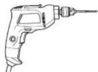
REQUIRED TOOLS
Phillips Screwdriver Drill
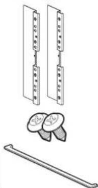
MATERIALS INCLUDED
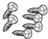
4X14
6 Wood Screws for Mounting
4X24
6 Wood Screws for Mounting
(for Flush Installation)
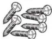
4X22
Self-Tapping Screws
for Cover Bracket
natural_image
Technical line drawing of a mechanical assembly with multiple components and a rod (no text or symbols)Cover Brackets for Flush Installation
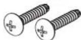
4X10 2 Screws for bottom decorative trim
Bottom decorative trim
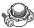
MATERIALS NEEDED
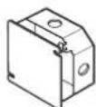
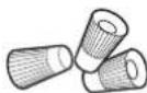
Junction Box Wire Nuts
36" (91 cm) of String
3/4" Conduit Connector
INSTALLATION REQUIREMENTS Part 2
1 INSTALLATION DRAWINGS (SKSSV3001S, FOR 30" SINGLE BUILT-IN OVEN)
The first step of the installation is to measure the current cutout dimensions and compare them to the cutout dimensions shown below. Little or no cabinet work may be necessary.
IMPORTANT NOTE
- The cabinet base platform must be able to support 190 lbs (86 kg). If the cabinet does not have a solid bottom, two braces or runners must be installed level with the bottom of the cutout to support the weight of the oven. Make sure the base is level and the front of the cabinet is square. If the cabinet base is not level, the oven racks will tend to slide out when opening the door.
- If marks, blemishes or the cutout opening are visible above the installed oven, it may be necessary to add wood shims under the runners and front trim until the marks or opening are covered.
- If the cabinet does not have a front frame and the sides are less than 3/4" (1.9 cm) thick, shim both sides equally to establish the cutout width.
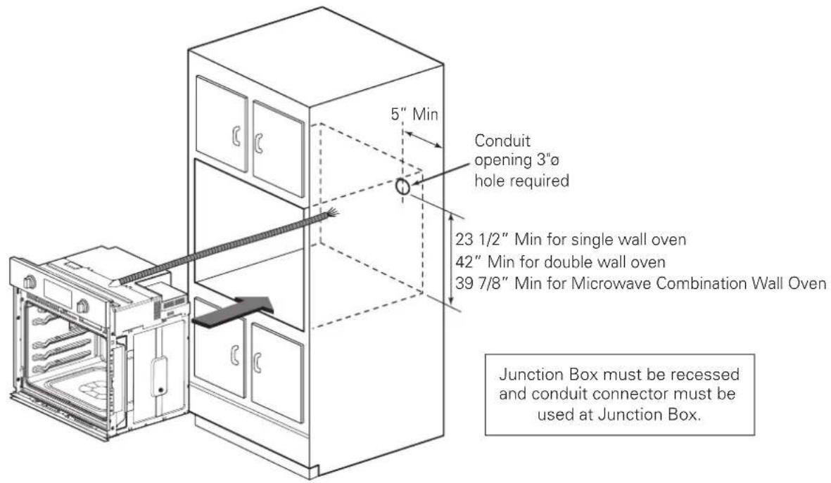
- The junction box must be flush with the rear wall of the cabinet as shown below.
- Allow at least a 23" clearance for the door depth when it is open.
- Kitchen cabinets in contact with the oven must be heat resistant up to 194°F (90°C), and fronts of nearby units up to at least 158°F (70°C).
- Do not remove the gliding racks from the base packing. Gliding racks are attached separately to the top and bottom of the oven.
1 Conduit opening
② Circuit breaker
| - Dimensions Single Oven | ||
| A Height 29 7/16" (747 mm) | ||
| B Width 29 3/4" (755 mm) | ||
| C Depth 23 3/8" (593 mm) | ||
| D Height (standard installation) 29" (736 mm) | ||
| E Height (power cord) 27 1/2" (699.5mm) | ||
| F Length (power cord) 60" (1524 mm) | ||
| G Width (back) 27 3/8" (695.3 mm) | ||
| H Width (standard installation) 28 3/7" (722 mm) | ||
| I Cabinet width 30" (762 mm) | ||
| J Overlap of oven | 1" (25.4 mm) | |
| K Cutout width | 28 1/2" Min. (723.9 mm), 28 5/8" Max. (727 mm) | |
| L Depth of open door | 23" (584.2 mm) | |
| M Cutout height | 29 1/8" Min. (740 mm), 29 3/16" Max. (741.4 mm) | |
| N Cutout depth 24" Min. (610 mm) | ||
| O Cutout location from floor | 31" (787.4 mm) | |
| P Height of conduit opening from floor of cutout | 23 1/2" (596.9 mm) | |
| Q Distance of conduit opening from side of cabinet | 5" (127mm) | |
Part 2 INSTALLATION REQUIREMENTS
Cutout Dimensions (Flush)
① Conduit opening
② Circuit breaker
| - Dimensions Single Oven | |
| C Cutout width 30" (762 mm) | |
| D Cleat (spacer) inset from front of cabinet | 1 3/8" (34.8mm) |
| E Cleat (spacer) width 3/16" (5 mm) | |
| F Cleat (spacer) depth 1" (25.4 mm) | |
| G Depth of open door 23" (584.2 mm) | |
| H Bottom of cutout from floor 31" (787.4mm) | |
| I Cutout depth 25" (635.0 mm) | |
| J Cleat (spacer) height 29 5/8" (752.4 mm) | |
| K Cutout height 28 9/16" (726 mm) | |
| L Height of conduit opening from floor of cutout | 23 1/2" (596.9 mm) |
| M Distance of conduit opening from side of cabinet | 5" (127mm) |
| N Bottom of bottom decorative trim to vent opening | 3/4" (19 mm) |
natural_image
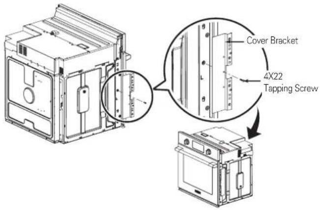
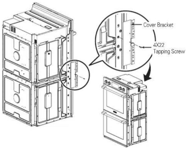
Line drawing of a multi-tiered kitchen appliance cabinet with doors, ovens, and a front panel (no text or symbols)- The provided cover brackets are only used for flush cabinet installations.
- Remove one screw from the left and right sides as shown. These screw holes will be used to mount the cover brackets. Install the cover brackets on the sides of the oven with the provided self-tapping screws.
Part 2 INSTALLATION REQUIREMENTS
2 INSTALLATION DRAWINGS (SKSSV3001S, FOR 30" SINGLE BUILT-IN OVEN UNDERCOUNTER)
The first step of the installation is to measure the current cutout dimensions and compare them to the cutout dimensions shown below. Little or no cabinet work may be necessary.
IMPORTANT NOTE
- The cabinet base platform must be able to support 190lbs (86kg). If the cabinet does not have a solid bottom, two braces or runners must be installed level with the bottom of the cutout to support the weight of the oven. Make sure the base is level and the front of the cabinet is square. If the cabinet base is not level, the oven racks will tend to slide out when opening the door.
- If marks, blemishes or the cutout opening are visible above the installed oven, it may be necessary to add wood shims under the runners and front trim until the marks or opening are covered.
- If the cabinet does not have a front frame and the sides are less than 3/4" (1.9 cm) thick, shim both sides equally to establish the cutout width.
- The junction box must be flush with the rear wall of the cabinet as shown below.
- This oven is only approved to be installed under the specific models as labeled on this unit.
- Kitchen cabinets in contact with the oven must be heat resistant up to 194°F (90°C), and fronts of nearby units up to at least 158°F (70°C).
- Do not remove the gliding racks from the base packing. Gliding racks are attached separately to the top and bottom of the oven.
Product Dimensions
Dimensions are the same as the single built-in oven.
Cutout Dimensions
Gas or electric cooktops may be installed over this oven. See cooktop installation instructions for cutout size. See label on top of oven for approved cooktop models.
CAUTION
• DO NOT block the oven air exhaust located at the bottom of the oven.
- Blocking the exhaust may cause cabinet damage and product malfunction.
-6-
Part 2 INSTALLATION REQUIREMENTS
Cutout Dimensions (Flush)
Gas or electric cooktops may be installed over this oven. See cooktop installation instructions for cutout size. See label on top of oven for approved cooktop models.
Part 2 INSTALLATION REQUIREMENTS
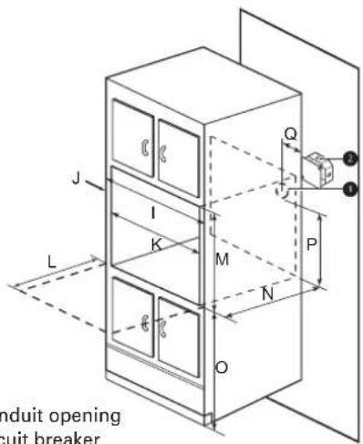
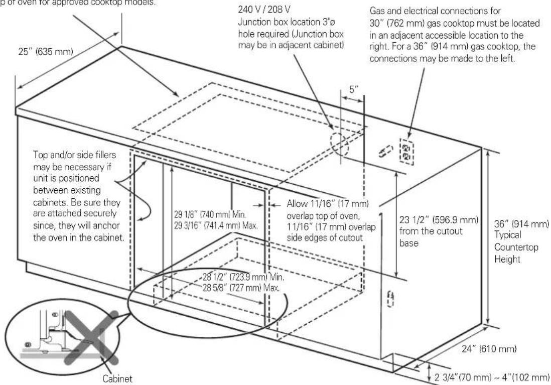
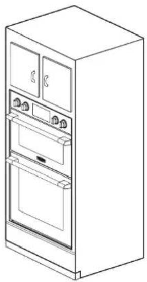
3 INSTALLATION DRAWINGS (SKSDV3002S, FOR 30" DOUBLE BUILT-IN OVEN)
The first step of the installation is to measure the current cutout dimensions and compare them to the cutout dimensions shown below. Little or no cabinet work may be necessary.
IMPORTANT NOTE
- The cabinet base platform must be able to support 325lbs (147kg). If the cabinet does not have a solid bottom, two braces or runners must be installed level with the bottom of the cutout to support the weight of the oven. Make sure the base is level and the front of the cabinet is square. If the cabinet base is not level, the oven racks will tend to slide out when opening the door.
- If marks, blemishes or the cutout opening are visible above the installed oven, it may be necessary to add wood shims under the runners and front trim until the marks or opening are covered.
- If the cabinet does not have a front frame and the sides are less than 3/4" (1.9 cm) thick, shim both sides equally to establish the cutout width.
- The junction box must be flush with the rear wall of the cabinet as shown below.
- Allow at least a 23" clearance for the door depth when it is open.
- Kitchen cabinets in contact with the oven must be heat resistant up to 194°F (90°C), and fronts of nearby units up to at least 158°F (70°C).
- Do not remove the gliding racks from the base packing. Gliding racks are attached separately to the top and bottom of the oven.
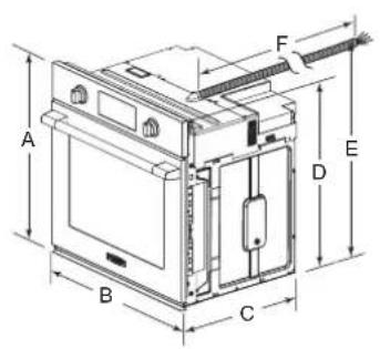
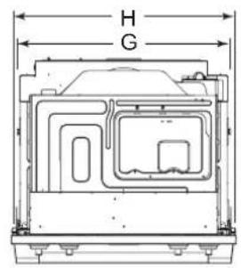
1 Conduit opening
② Circuit breaker
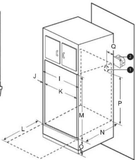
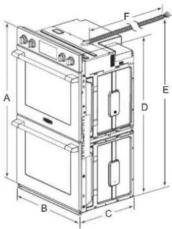
| - Dimensions Double Oven | ||
| A Height 52 1/16" (1323 mm) | ||
| B Width 29 3/4" (755 mm) | ||
| C Depth 23 3/8" (593 mm) | ||
| D Height (standard installation) 51 9/16" (1310 mm) | ||
| E Height (power cord) 50 5/16" (1277.2 mm) | ||
| F Length (power cord) 60" (1524 mm) | ||
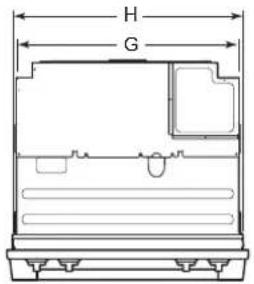
| G Width (back) 27 3/8" (695.3 mm) | ||
| H Width (standard installation) 28 3/7" (722 mm) | ||
| I Cabinet width 30" (762 mm) | ||
| J Overlap of oven | 1" (25.4 mm) | |
| K Cutout width | 28 1/2" Min. (723.9 mm), 28 5/8" Max. (727 mm) | |
| L Depth of open door | 23" (584.2 mm) | |
| M Cutout height | 51 13/16" Min. (1316 mm), 51 15/16" Max. (1319.2 mm) | |
| N Cutout depth 24" Min. (610 mm) | ||
| O Cutout location from floor | 12" (304.8 mm) | |
| P Height of conduit opening from floor of cutout | 47" (1193.8 mm) | |
| Q Distance of conduit opening from side of cabinet | 5" (127 mm) | |
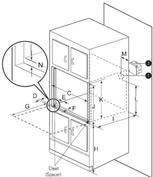
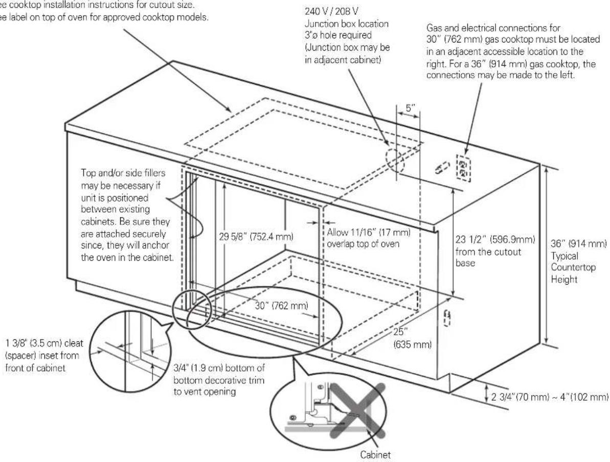
Part 2 INSTALLATION REQUIREMENTS
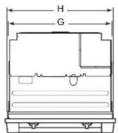
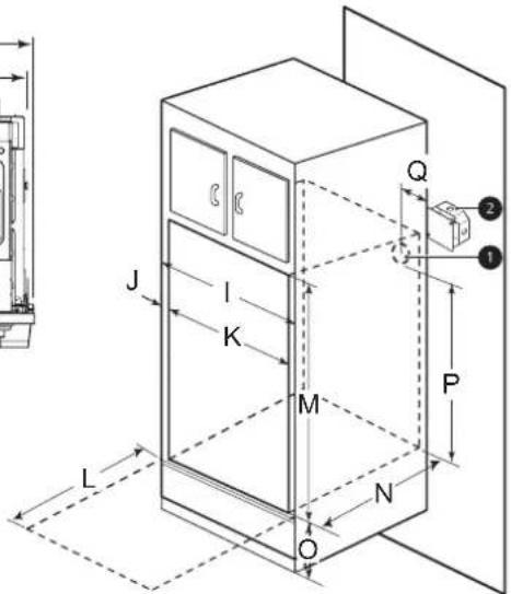
Cutout Dimensions (Flush)

| - Dimensions Double Oven | ||
| C | Cutout width 30" (762 mm) | |
| D | Cleat (spacer) inset from front of cabinet | 1 3/8" (34.8 mm) |
| E | Cleat (spacer) width 3/16" (5 mm) | |
| F | Cleat (spacer) depth 1" (25.4 mm) | |
| G | Depth of open door 23" (584.2 mm) | |
| H | Bottom of cutout from floor 12" (304.8mm) | |
| I | Cutout depth 25" (635.0 mm) | |
| J | Cleat (spacer) height 52 5/16" (1329 mm) | |
| K | Cutout height 51 9/32" (1303 mm) | |
| L | Height of conduit opening from floor of cutout | 47" (1193.8 mm) |
| M | Distance of conduit opening from side of cabinet | 5" (127 mm) |
| N | Bottom of bottom decorative trim to vent opening | 3/4" (19 mm) |
natural_image
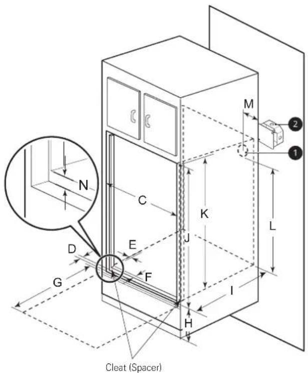
Line drawing of a double-door refrigerator with open doors and front panels (no text or symbols)- The provided cover brackets are only used for flush cabinet installations.
- Remove one screw from the left and right sides as shown. These screw holes will be used to mount the cover brackets. Install the cover brackets on the sides of the oven with the provided self-tapping screws.
Part 2 INSTALLATION REQUIREMENTS
4 INSTALLATION DRAWINGS (SKSCV3002S, FOR 30" MICROWAVE COMBINATION WALL OVEN)
The first step of the installation is to measure the current cutout dimensions and compare them to the cutout dimensions shown below. Little or no cabinet work may be necessary.
IMPORTANT NOTE
- The cabinet base platform must be able to support 202 lbs (91.65 kg). If the cabinet does not have a solid bottom, two braces or runners must be installed level with the bottom of the cutout to support the weight of the oven. Make sure the base is level and the front of the cabinet is square. If the cabinet base is not level, the oven racks will tend to slide out when opening the door.
- If marks, blemishes or the cutout opening are visible above the installed oven, it may be necessary to add wood shims under the runners and front trim until the marks or opening are covered.
- If the cabinet does not have a front frame and the sides are less than 3/4" (1.9 cm) thick, shim both sides equally to establish the cutout width.
- The junction box must be flush with the rear wall of the cabinet as shown below.
- Allow at least a 23" clearance for the door depth when it is open.
- Kitchen cabinets in contact with the oven must be heat resistant up to 194°F (90°C), and fronts of nearby units up to at least 158°F (70°C).
- Do not remove the gliding racks from the base packing. Gliding racks are attached separately to the top and bottom of the oven.
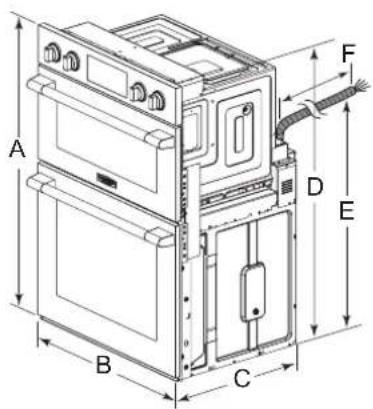
① Conduit opening ② Circuit breaker
| - Dimensions Single Oven | |
| A Height | 43 13/16" (1113 mm) |
| B Width | 29 3/4" (755 mm) |
| C Depth | 23 3/8" (593 mm) |
| D Height (standard installation) | 43 3/16" (1097 mm) |
| E Height (power cord) | 27 3/16" (690 mm) |
| F Length (power cord) | 60" (1524 mm) |
| G Width (back) | 27 3/8" (695.3 mm) |
| H Width (standard installation) | 28 3/7" (722 mm) |
| I Cabinet width | 30" (762 mm) |
| J Overlap of oven | 1" (25.4 mm) |
| K Cutout width | 28 1/2" Min. (723.9 mm), 28 5/8" Max. (727 mm) |
| L Depth of open door | 23"(584.2 mm) |
| M Cutout height | 43 7/16" Min. (1103 mm), 43 1/2" Max. (1106 mm) |
| N Cutout depth | 24" Min. (610 mm) |
| O Cutout location from floor | 12" (304.8 mm) |
| P Height of conduit opening from floor of cutout | 39 7/8" (1012.8 mm) |
| Q Distance of conduit opening from side of cabinet | 5" (127mm) |
Part 2 INSTALLATION REQUIREMENTS
Cutout Dimensions (Flush)
| - Dimensions Combi Oven | ||
| C | Cutout width 30" (762 mm) | |
| D | Cleat (spacer) inset from front of cabinet | 1 3/8" (34.8mm) |
| E | Cleat (spacer) width 13/64" (5 mm) | |
| F | Cleat (spacer) depth 1" (25.4 mm) | |
| G | Depth of open door 23" (584.2 mm) | |
| H | Bottom of cutout from floor 12" (304.8 mm) | |
| I | Cutout depth 25" (635.0 mm) | |
| J | Cleat (spacer) height 44" (1118 mm) | |
| K | Cutout height 43 13/16" (1113 mm) | |
| L | Height of conduit opening from floor of cutout | 39 7/8" (1012.8 mm) |
| M | Distance of conduit opening from side of cabinet | 5" (127mm) |
| N | Bottom of bottom decorative trim to vent opening | 3/4" (19 mm) |
natural_image
Line drawing of a single refrigerator with doors, ovens, and front panels (no text or symbols)- The provided cover brackets are only used for flush cabinet installations.
- Remove one screw from the left and right sides as shown. These screw holes will be used to mount the cover brackets. Install the cover brackets on the sides of the oven with the provided self-tapping screws.
Part 2 INSTALLATION REQUIREMENTS
5 PREPARATION FOR MOVING THE OVEN
The second step of the installation is to remove any packing material from the oven before installing the oven.
- Remove all tape from around the oven.
- Open the oven door and remove packaging materials and oven racks inside the oven.
- Door removal is not a requirement for installation of the oven, but is an added convenience. To remove the door, follow the steps below.
Step. 1
Fully open the door.
Step. 2
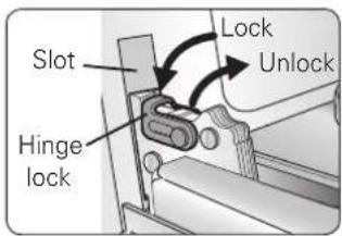
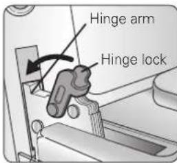
Pull the hinge locks up towards the door's frame, to the unlocked position.
Step. 3
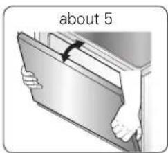
Firmly grasp both sides of the door at the top.
Step. 4
Close door to the door removal position, which is approximately 5 degrees.
Step. 5
Lift door up and out until the hinge arm is clear of the slot.
- Place the oven on a table or platform even with the cutout opening. (The table or platform must support 190 lbs [86 Kg] for a single built-in oven, 325 lbs [147 Kg] for a double built-in oven, 202 lbs [91.65 kg] for a Microwave Combination Wall Oven.)
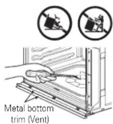
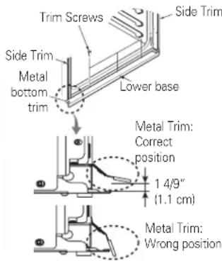
- Remove the metal bottom trim from the oven. It will be installed at the end of the installation process. The trim is wrapped separately and taped to the top of the unit.

CAUTION
- Make sure the cabinets and wall coverings around the oven can withstand the temperature (up to 194 °F [90 °C]) generated by the oven.
- Discoloration, delamination or melting may occur.

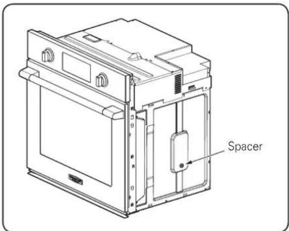
CAUTION
• DO NOT remove spacers on the side walls of the built-in oven.
- These spacers center the oven in the space provided. The oven must be centered to prevent excess heat buildup that may result in heat damage or fire.
IMPORTANT NOTE
- Do not lift the door by the handle. The oven door is very heavy. Firmly grasp the door by the sides before lifting it off the hinges.
- Do not lay the oven door on its handle. Doing so may cause dents or scratches.
- Use two or more people to lift or move the oven into the cabinet opening. Use caution when lifting the oven and wear gloves to protect hands from any sharp edges. Failure to follow these instructions may result in injury.
Part 3 ELECTRICAL CONNECTIONS
1 ELECTRICAL CONNECTION REQUIREMENTS
The third step of the installation is to follow the electrical connection requirements below.
Ensure that dedicated circuit protection is prepared as recommended and that the oven is grounded properly.
IMPORTANT NOTE
Be sure the wall oven is installed and grounded properly by a qualified installer or service technician.
- This wall oven must be electrically grounded in accordance with local codes or, in their absence, with the National Electrical Code ANSI/NFPA No.70- latest edition in United States, or with CSA Standard C22.1-1982 and C22.2 No.01982 (or latest edition), Canadian Electrical Code, Part1, and all local codes and ordinances.
- This wall oven must be supplied with the proper voltage and frequency, and connected to an individual, properly grounded branch circuit, protected by a circuit breaker or fuse. To know the circuit breaker or fuse required by this model, see the rating plate to find the wattage consumption and refer to the table below to get the circuit breaker or fuse amperage.
[Appliance rating Watts 240 V]
| Category Power Co | Consumption Protection circuit | recommended | Wire gauge recommended |
| Single wall oven 6100 | W 40 A 12 AWG | ||
| Double wall oven 1020 | W 50 A 8 AWG | ||
| Combi wall oven 7800 | W 40 A 10 AWG |
[Appliance rating Watts 208 V]
| Category Power Co | Consumption Protection circuit | recommended | Wire gauge recommended |
| Single wall oven 4600 | W 30 A 12 AWG | ||
| Double wall oven 7700 | W 50 A 8 AWG | ||
| Combi wall oven 6200 | W 40 A 10 AWG |
IMPORTANT NOTE
- Do Not ground to a gas pipe.
- Do Not have a fuse in the neutral or grounding circuit.
- A U.L.-listed conduit connector must be provided at the junction box.

WARNING
- New branch-circuit installations (1996 NEC), mobile homes, recreational vehicles, or installations where local codes prohibit grounding through the neutral conductor require 4-wire branch-circuit connection.

WARNING
- Improper connection of aluminum house wiring to copper leads can result in an electrical hazard or fire. Use only connectors designed for joining copper to aluminum and follow the manufacturer's recommended procedure closely.
Part 3 ELECTRICAL CONNECTIONS
2 ELECTRICAL CONNECTION
The fourth step of the installation is to prepare the electrical connection as follows:
- Turn off the circuit breaker or remove fuses to the oven branch circuit.
- With the oven positioned directly in front of the cabinet opening, connect the flexible conduit to the electrical junction box as shown below. Position the conduit in such a manner that it will lie on top of the oven in a natural loop when the oven is installed.
- If local codes permit connection of the frame grounding conductor to the neutral(white) wire, follow the instructions for a 3-wire circuit connection. If used in mobile homes or new construction, or a recreational vehicle, or local codes do not permit connection of the frame grounding conductor to the neutral (white) wire, follow the instructions for a 4-wire circuit connection.
IMPORTANT NOTE
- The wall ovens must be hard wired (direct wired) into an approved junction box. A plug and receptacle is not permitted on these products.
- DO NOT shorten the flexible conduit. The conduit connector must be securely attached to the junction box and the flexible conduit must be securely attached to the conduit connector. If the flexible conduit will not fit within the connector, do not install the oven until a connector of the proper size is obtained.
NOTE TO ELECTRICIAN
The power leads supplied with the appliance are UL, CSA recognized for connection to larger gauge household wiring. The insulation of these leads is rated at temperatures much higher than the temperature rating of household wiring. The current carrying capacity of the conductor is governed by the wire gauge and the temperature rating of the insulation around the wire.
Part 3 ELECTRICAL CONNECTIONS
IMPORTANT NOTE
- You will need to purchase an appropriate conduit connector to complete the connection of the conduit to the junction box.
3-Wire Circuit Connection 4-Wi
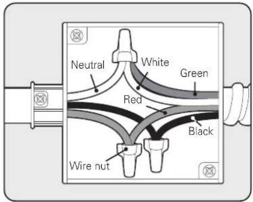
To connect to a three-wire circuit, follow these steps:
- Connect the oven's ground (green) wire and neutral (white) wire to the branch circuit's neutral (white or gray) wire, using a wire nut.
- Connect the oven's red wire to the branch circuit's red (L2) wire in accordance with local codes, using a wire nut.
- Connect the oven's black wire to the branch circuit's black (L1) wire in accordance with local codes, using a wire nut. If the house wiring uses aluminum conductors, see the WARNING.
- Install the junction box cover.
Junction Box
Circuit Connection
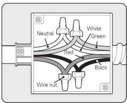
To connect to a four-wire circuit, follow these steps:
- Separate the oven's ground and white wires if necessary.
- Connect the oven's ground (green) wire to the branch circuit's ground (green) wire in accordance with local codes, using a wire nut. If the house wiring uses aluminum conductors, see the WARNING.
- Connect the oven's white wire to the branch circuit's neutral (white or gray in color) wire in accordance with local codes, using a wire nut.
- Connect the oven's red wire to the branch circuit's red (L2) wire in accordance with local codes, using a wire nut.
- Connect the oven's black wire to the branch circuit's black (L1) wire in accordance with local codes, using a wire nut. If the house wiring uses aluminum conductors, see the WARNING.
- Install the junction box cover.
Junction Box
Part 4 INSTALL THE OVEN
1 CABINET INSTALLATION
Install the oven into the cabinet as follows :
- Sliding the oven into the opening.
a. Loop (do not tie) a 36" (91 cm) string around the conduit before the oven is slid into place. Lay the string over the top of the oven and use it to keep the conduit from falling behind the oven.
b. Lift oven into cabinet cutout using the oven opening as a grip. Carefully push against the oven front frame. Do not push against outside edges.
c. While sliding the oven back, pull the string so that the conduit lies on the top of the oven in a natural loop.
d. When you are sure the conduit is out of the way, slide the oven 3/4 of the way back into the opening. Remove the string by pulling on one end of the loop.

CAUTION
• DO NOT block the oven air exhaust located at the bottom of the oven.
- Blocking the exhaust may cause cabinet damage and product malfunction.
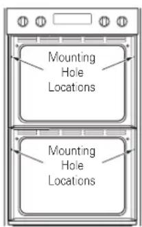
- Securing the oven.
a. Using the mounting holes on the oven side trim as a guide, drill pilot holes for screws provided (For securing the double wall oven, use a minimum of 4 screws, one on each side in both the upper and lower ovens. For securing the single wall oven, use a minimum of 2 screws, one on each side. For securing the Combi Oven, use a minimum of 4 screws, one on each side in both the upper and lower ovens.)
b. Secure the oven to the cabinet with screws provided.
If the cabinet is particle board, you must use 3/4" particle board screws. These may be purchased at any hardware store.
- Reinstall the oven door.

WARNING
- Mounting screws must be used.
- Failure to do so can result in the oven falling out of the cabinet causing serious injury.
- Ensure that the metal bottom trim is correctly installed.
- When you install the oven door, be careful not to bump the metal bottom trim.
- Keep oven vents unobstructed. Replace the bottom trim if it becomes bent or deformed. Never block the vent with plastic or heat-sensitive items.
Part 4 INSTALL THE OVEN
Step. 1
Firmly grasp both sides of the door at the top.
Step. 2
With the door at the same angle as the removal position, seat the indentation of the hinge arm into the bottom edge of the hinge slot. The notch in the hinge arm must be fully seated into the bottom of the slot.
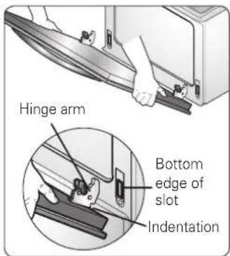
Step. 3
Fully open the door. If the door will not fully open, the indentation is not seated correctly in the bottom edge of the slot.
Step. 4
Push the hinge locks up against the front frame of the oven cavity to the locked position.
Step. 5
Close the oven door.
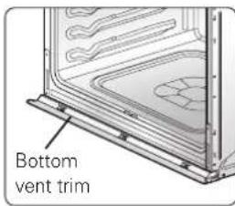
NOTE
When you install the oven door, be careful not to bump the bottom vent trim.
Keep oven vents unobstructed. Replace the bottom vent trim if it
becomes bent or deformed. Never block the vent with plastic or heat-sensitive items.
2 ASSEMBLING THE BOTTOM DECORATIVE TRIM
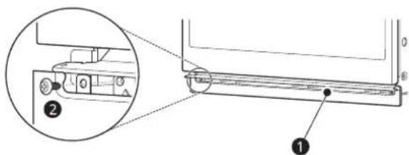
① Bottom decorative trim
• After installing the oven in the cabinet, assemble bottom decorative trim with 2 screws ② (4X10).
OPERATION CHECKLIST
Each of the functions has been factory checked before shipping. However, it is suggested that you verify the operation of the oven once more. Refer to the Owner's Manual. Follow the instructions for the basic check.
Common
- Turn on power supply. The initial signal sound will be heard.
- Check the operation of the broil mode. When the oven is set to broil, the upper element in the oven should become red. After a few minutes, partially open the oven door. You should feel heat from the oven. Adjust the oven mode knob to OFF position.
- Check the operation of the bake mode. After setting the oven to 350 °F / 177 °C for baking, the temperature of the oven in the display should increase. Adjust the oven mode knob to OFF position.
- Check the operation of the convection bake mode. After setting the oven to 350 °F / 177 °C for convection baking, the fan inside the oven should come on with the door closed. Adjust the oven mode knob to OFF position.
- Turn on and off the oven light to check the lights are in normal condition.
- Check the operation of the burner for each convection mode. After setting the oven to 350 °F / 177 °C for each convection mode, the fan inside the oven should come on with door closed.
Combi Oven Only
- Check the Microwave function. Place a glass bowl filled with water in upper oven. Turn the microwave on for 1 minute. The water should be hot. Adjust the oven mode knob to OFF
IMPORTANT NOTE
- A small amount of smoke and odor may be noticeable during the initial break-in period.
- If the oven does not operate properly or an F-, followed by a number, appears in the display, see the Owner's Manual for the troubleshooting list. The list includes common occurrences that are not the result of defective workmanship or materials in this product. If the problem occurs continuously, contact the dealer.
- Refer to the warranty in the Owner's Manual for the LG toll-free service number and address.
SIGNATURE
KITCHEN SUITE
FOUR MURAL COMBINÉ
FOUR À CONVECTION ÉLECTRIQUE ENCASTRÉ
SKSSV3001S
SKSDV3002S
SKSCV3002S

MFL51224811_01
www.signaturekitchensuite.ca