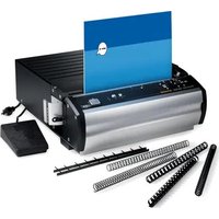
MP2500iX - Binder GBC - Free user manual and instructions
Find the device manual for free MP2500iX GBC in PDF.


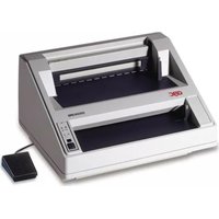
| Product Type | Electric Binding Machine / Punch |
| Brand | GBC |
| Model | MP2500iX |
| Dimensions (W × H × D) | 457 mm × 216 mm × 406 mm |
| Weight | 23.3 kg |
| Power Supply | 115 V~60 Hz, 1.6 A or 230 V~50-60 Hz, 1.1 A |
| Activation | Pneumatic foot pedal or manual switch |
| Maximum Paper Width | Up to A4 (open throat) |
| Punching Capacity per Cycle | Varies by die set: up to 25 sheets (80 g/m²) for certain sets |
| Supported Binding Types | Plastic (PB), Metal Spiral (3:1, 2:1), VeloBind, SureBind, Loose Sheets (2-4/3-5-7) |
| Number of Punch Pins | Varies by die set (e.g., 21 for PB, 47 for 4:1, 34 for 3:1, 23 for 2:1, 11 for loose sheets, 12 for VB, 10 for SB) |
| Die Change | Tool-free, self-locking |
| Main Functions | Punching, automatic reverse anti-jam, adjustable margin guide, LED indicators (power, die missing, waste bin full), waste bin with level alert |
| Safety | Automatic stop when waste bin is full, safety lock, non-removable cover |
| Maintenance | Regularly empty waste bin; clean pins with a slightly oiled cloth |
| Spare Parts | Die storage rack (ref. 7703207) |
| General Information | All-metal construction, designed for tabletop use |
Frequently Asked Questions - MP2500iX GBC
User questions about MP2500iX GBC
0 question about this device. Answer the ones you know or ask your own.
Ask a new question about this device
Download the instructions for your Binder in PDF format for free! Find your manual MP2500iX - GBC and take your electronic device back in hand. On this page are published all the documents necessary for the use of your device. MP2500iX by GBC.
USER MANUAL MP2500iX GBC
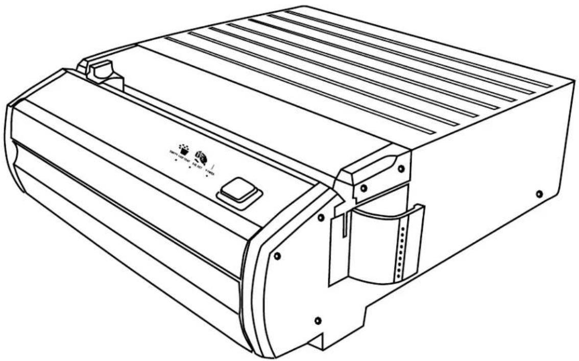
GBC Modular Series Punch
Model No. MP2500iX
natural_image
Line drawing of a mechanical device with ribbed top and mounting bracket (no text or symbols)SAFETY MESSAGES AVVERTENZE PER LA SICUREZZA SICHERHEITSHINWEISE
The safety of you and others is very important to GBC. Important safety messages and information are contained within this manual as well as on the machine itself. Please be certain to carefully read and understand all of these before operating the machine.

The safety alert symbol precedes each safety message in this
Operating Instructions manual. This symbol indicates a potential personal safety hazard that could hurt you or others as well as cause product or property damage.
The following pictorial is found on the MP2500iX :
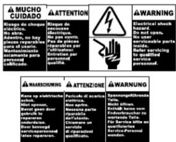
This safety message means that you could be seriously hurt or killed if you open the product and expose yourself to hazardous voltage. NEVER remove the machine's outer cover. ALWAYS refer service requirements to qualified GBC Personnel.
The following ISO and IEC symbols appear on this product, their meaning is:

Means Punch

Means Empty Chip Tray

Means Die Set Out
- Use the MP2500iX only for its intended purpose of punching paper and covers according to the indicated specifications.
- Before operating the machine, make certain that the MP2500iX is placed on a secure, stable work area. This will help prevent the machine falling and possibly causing personal injury and damage.
- Retain this Operating Instructions manual for later use.

CAUTION: IN CASE OF EMERGENCY, USE THE POWER CORD AS A MAIN DISCONNECT DEVICE!
- The MP2500iX must be connected to a supply voltage corresponding to the electrical rating in the machine operating instructions (also listed on the serial number label).
- The socket-outlet shall be located near the equipment and shall be easily accessible.
- The grounding plug is a safety feature and will only fit into the proper grounding-type power outlet. If you are unable to insert the plug into an outlet, contact a qualified electrician to have a suitable outlet installed. Do not alter the plug on the end of the cordset (if provided) of the MP2500iX. It was provided for your safety.
- Unplug the MP2500iX before moving the machine or whenever the machine is not in use for an extended period of time.
- Do not operate the MP2500iX if the machine has a damaged power supply cord or plug. Do not operate the machine after any malfunction, if liquid has been spilled into the machine, or if the machine has been damaged in any way.
-
Do not overload electrical outlets beyond their capacity. To do so can result in fire or electrical shock.
-
Usare la MP2500iX solo per lo scopo previsto, ovvero la rilegatura di perforuzione e copertine secondo i dati tecnici indicati.
- Prima di mettere in funzione la macchina, accertare che sia sistemata in una posizione di lavoro sicura e stabile. In questo modo si eviterà che la macchina possa cadere provocando lesioni alle persone e danni a proprietà.
- Conservare queste istruzioni per l'uso per poterle consultare in futuro.
CAUTION: WHEN CHOOSING A DETACHABLE LINE CORD FOR USE WITH YOUR MP2500iX, ALWAYS OBSERVE THE FOLLOWING PRECAUTIONS:
The cordset consist of three parts; the attachment plug, cordage and appliance inlet. Each of these components must have European regulatory approvals for safety.
The following minimum electrical ratings for the specific cordset are published for safety purposes. DO NOT USE CORDSETS THAT DO NOT MEET THE FOLLOWING MINIMUM ELECTRICAL REQUIREMENTS.
PLUG: 3 ampere, 250 volts, 50/60 Hz, Class 1, 3 conductor, European safety approved.
CORDAGE: Type H03VV-F3G0.75, Harmonized (< HAR>). The "<>" symbols indicate cordage approved to appropriate European standard (NOTE: "HAR" may be substituted by the approval mark of the European safety agency which approved the cordage. An example would be "< VDE >".)
APPLIANCE CONNECTOR: 3 ampere, 250 volts, 50/60 Hz, European safety approved, Type IEC 320. The cordset shall not exceed 3 meters in length. A cordset with component electrical ratings greater than the minimum specified electrical ratings may be substituted.
(LE NOTE CHE SEGUONO PERTENGONO SOLO ALLE MACCHINE ALIMENTATE A 230 V 50/60 HZ.)

ATTENZIONE: NELLA SCELTA DI UN CAVO DI ALIMENTAZIONE STACCABILE PER L'IMPIEGO CON LA MP2500IX, OSSERVARE SEMPRE LE PRECAUZIONI CHE SEGUONO
This equipment has been tested and found to comply with the limits for a Class A digital device, pursuant to Part 15 of the FCC Rules. These limits are designed to provide reasonable protection against harmful interference when the equipment is operated in a commercial environment. This equipment generates, uses, and can radiate radio frequency energy and, if not installed and used in accordance with the Operator Manual, may cause harmful interference to radio communications. Operation of this equipment in a residential area is likely to cause harmful interference in which case the user will be required to correct the interference at his/her own expense.

CAUTION: CHANGES OR MODIFICATIONS NOT EXPRESSLY APPROVED BY GENERAL BINDING CORPORATION COULD VOID YOUR AUTHORITY TO OPERATE THE EQUIPMENT.
This Class A digital apparatus meets all requirements of the Canadian Interference-Causing Equipment Regulations.
(LE NOTE CHE SEGUONO PERTENGONO SOLO ALLE MACCHINE ALIMENTATE A 115 V 60 HZ.)
Thank you for purchasing the MP2500iX. It is a versatile production system that will enable you to punch documents for a variety of binding styles with a simple die set change. It has also been designed for easy operation.
The MP2500iX offers an all-metal construction to provide a longer life and greater durability. Though ruggedly built, the MP2500iX is compact and light enough to be used on any table or desk. As part of the GBC Modular product line, a modular binder can stack easily on top of the MP2500iX. Or, the binder can be separated for greater productivity.
The MP2500iX is an innovative solution for punching paper and offers the following design features:
- Quick-change die sets that are self-latching without tools or levers.
- All MP2500iX die sets include a Pin Label providing sheet capacity, and pull pin information for punching standard size documents.
- Exclusive Auto -Reverse Jam Stopper electronics, preventing downtime due to paper jams.
- A vertical Open-Throat punching design allows for easy alignment of various sheet sizes in the punching throat, utilizing gravity and minimizing punching skew.
- An easily adjustable edge guide allows for alignment of paper or oversized covers.
- Convenient LED's indicate:
- That POWER is on.
- When a DIE SET is not in.
- When the chip tray needs to be emptied. To prevent chip tray overfill, the LED flashes to warn you the tray is nearly full (after approximately 250 cycles), then after another several cycles, the POWER LED will go off and the EMPTY CHIP TRAY LED will shine steady and the machine is disabled until the chip tray is emptied.
- Choose between a palm switch or a hands free foot pedal to activate punching.
These instructions have been prepared to acquaint you with the MP2500iX punch and its operation. Please read them carefully. Keep these operating instructions
Unpack the MP2500iX punch.
Set the MP2500iX on a convenient work surface and remove packaging used for shipping.
Place on any suitable table or desk convenient to a power outlet.
Firmly push the square end of the power cord (A) into the power cord receptacle (B) located on the back of the machine.

CAUTION: MAKE SURE THIS STEP IS COMPLETE PRIOR TO PLUGGING THE MALE END OF THE POWER CORD INTO A POWER RECEPTACLE.
Plug the pronged end of the power cord into an appropriate power receptacle.
Press the foot pedal hose end (C) into the round connector (D) on the back of the machine.
DISIMBALLO E MESSA A PUNTO
Figure 1b
I
| OPERATING CONTROLS | COMANDI OPERATIVI |
| A. POWER CORD | A. CAVO DI ALIMENTAZIONE |
| B. POWER RECEPTACLE | B. PRESA DI ALIMENTAZIONE |
| C. FOOT PEDAL | C. COMANDO A PEDALE |
| D. FOOT PEDAL RECEPTACLE | D. PRESA COMANDO A PEDALE |
| E. ON/OFF SWITCH | E. INTERRUTTORE ACCESO/SPENTO |
| F. FUSE HOLDER | F. PORTAFUSIBILI |
| G. PALM SWITCH | G. INTERRUTTORE A MANO |
| H. LED INDICATORS | H. INDICATORI LED |
| I. EDGE GUIDE | I. GUIDA PER I BORDI |
| J. EDGE GUIDE KNOB | J. MANOPOLA GUIDA PER I BORDI |
| K. CHIP TRAY | K. VASSOIO RESIDUI CARTA |
| L. DIE SET SLOT | L. SEDE STAMPO |
| M.DIE SET | M.STAMPO |
| N. DIE SET HANDLE | N. IMPUGNATURA STAMPO |
| O. PUNCH THROAT | O. SUPPORTO PER LA PERFORAZIONE |
| P. PUNCH PINS | P. PERNI DI PERFORAZIONE |
| Q. PUNCH PIN RETAINER | Q. FERMO PERNI DI PERFORAZIONE |
| R. DEPTH OF PUNCH SELECTOR (PB ONLY) | R. PROFONDITÀ DEL SELETTORE DI PERFORAZIONE (SOLO PB) |
D
NL
F
E
| BEDIENELEMENTE | BEDIENINGSORGANEN | COMMANDES | MANDOS DE FUNCIONAMIENTO |
| A. NETZKABEL | A. NETSNOER | A. CORDON D'ALIMENTATION | A. CORDÓN ELÉCTRICO |
| B. BUCHSE FÜR NETZKABEL | B. NETAANSLUITING | B. PRISE D'ALIMENTATION | B. ENCHUFE HEMBRA |
| C. FUSSSCHALTER | C. VOETPEDAAL | C. PÉDALE | C. PEDAL |
| D. BUCHSE FÜR FUSSSCHALTER | D. VOETPEDAALAANSLUITING | D. PRISE DE LA PÉDALE | D. ENCHUFE HEMBRA DEL PEDAL |
| E. NETZSCHALTER | E. AAN/UIT-SCHAKELAAR | E. INTERRUPTEUR M/A | E. INTERRUPTOR DE APAGADO Y ENCENDIDO |
| F. SICHERUNGSHALTERUNG | F. ZEKERINGHOUDER | F. PORTE-FUSIBLE | F. PORTAFUSIBLES |
| G. HANDSCHALTER | G. HANDSCHAKELAAR | G. INTERRUPTEUR MANUEL | G. INTERRUPTOR MANUAL |
| H. LED-ANZEIGEN | H. LED-INDICATOREN | H. VOYANTS DEL | H. INDICADORES LED |
| I. KANTENFÜHRUNG | I. KANTGELEIDING | I. GUIDE MARGEUR | I. GUÍA DEL BORDE |
| J. SCHALTER FÜR KANTENFÜHRUNG | J. KNOP KANTGELEIDING | J. BOUTON DU GUIDE MARGEUR | J. BOTÓN DE LA GUÍA DEL BORDE |
| K. PAPIERSCHNITZELFACH | K. OPVANGBAK | K. BAC À CONFETTIS | K. BANDEJA DE DESPERDICIOS |
| L. EINSCHUB FÜR LOCHERBLOCK | L. SLEUF PONSSET | L. LOGEMENT DE L'ENSEMBLE MATRICE | L. RANURA DEL JUEGO DE TROQUEL |
| M.LOCHERBLOCK | M. PONSSET | M.ENSEMBLE MATRICE | M. JUEGO DE TROQUEL |
| N. GRIFF DES LOCHERBLOCKS | N. HANDGREEP PONSSET | N. POIGNÉE DE L'ENSEMBLE MATRICE | N. ASA DEL JUEGO DE TROQUEL |
| O. HALTEPLATTE FÜR LOCHER | O. PONSVAK | O. GORGE D'ALIMENTATION | O. ALCANCE DE PERFORACIÓN |
| P. LOCHERSTIFTE | P. PONSPENNEN | P. BROCHES DE POINÇONNAGE | P. CLAVIJAS DE PERFORACIÓN |
| Q. HALTERUNG DER LOCHERSTIFTE | Q. PONSPENHOUDER | Q. RETENUE DES BROCHES DE POINÇONNAGE | Q. FIADOR DE LAS CLAVIJAS DE PERFORACIÓN |
| R. TIEFE DES LOCHERSELEKTORS (NUR PB) | R. DIEPTE VAN PONSSELECTOR (ALLEEN PB) | R. SÉLECTEUR DE PROFONDEUR DE POINÇONNAGE (PB UNIQUEMENT) | R. SELECTOR DE PROFUNDIDAD DE PERFORACIÓN (PB SOLAMENTE) |
TABLE 1
| Binding Style Punching Pattern | Die Set Label | |
| Plastic Binding (PB) | Cerlox (Plastic Comb) | PB 19/21 |
| Plastic Color Coil (C4) | 4:1 GBC (4 holes per inch, 0.2475" center-to-center hole spacing) | 4:1 GBC |
| Twin Loop Wire (W3) | 3:1 (3 square holes per inch) | 3:1 |
| Twin Loop Wire (W3) | 3:1 (3 round holes per inch) | 3:1 |
| Twin Loop Wire (W2) | 2:1 (2 square holes per inch) | 2:1 |
| Twin Loop Wire (W2) | 2:1 (2 round holes per inch) | 2:1 |
| VeloBind (VB) | 1 hole per inch | VB |
| SureBind (SB) | Approximately 1 hole per inch | SB |
| 3, 5 or 7 Hole Binding 11" | 3 holes across bound edge of document, 11" paper | 2-4/3-5-7 |
| 2 or 4 Hole Binding A4 | 4 holes across bound edge of document, A4 paper | 2-4/3-5-7 |
| 2 Hole Binding, 11" | 2 holes across bound edge of document, 8 1/2" paper, medical or legal clip board style | 2-4/3-5-7 |
PUNCHING
The MP2500iX uses a variety of easily interchangeable die sets that allow you to bind documents using many different binding styles. By selecting the appropriate die set, you can use your MP2500iX to punch documents in any of the binding styles indicated in Table 1.
Please note that each punching style listed above requires a separate die set for the MP2500iX. with the single exception of the 2-4/3-5-7 die set which handles Loose Leaf Binding styles in one die set.
IMPORTANT: A decal on the handle of each interchangeable die set indicates the punching pattern. When reading the Operating Instructions, please note the special instructions for the correct punching pattern die set that you have installed in your MP2500iX.
I
PERFORAZIONE
CAUTION: Before changing the MP2500iX die sets, make certain that the machine is turned OFF (O).
Your MP2500iX offers the convenience of interchangeable die sets, allowing you to economically punch documents for a wide variety of binding styles. Changing the machines die sets is both quick and easy, as the following instructions illustrate.
Removing Die Sets from the Machine (Figure 2): The interchangeable die set slot of the MP2500iX is located on the right front side of the machine. If a die set "M" is already installed in your MP2500iX, you can easily remove the die set by following these instructions:
Step 1: Insert fingers into the Die Set Handle located on the right side of the die set (Figure 1b, N).
Step 2: Securely grasp the handle and tug firmly (see Figure 2). This firm tug disengages the Automatic Latching Mechanism, and allows the die set to slide out.
Step 3: Continue pulling on the handle until the Die Set is fully removed.
Step 4: Properly store the removed Die Set (keep away from dust, dirt, accidental falls from the edge of counters etc.).
Helpful Hint: The GBC Die Set Storage Cabinet #7703207 is an excellent way to store all of your interchangeable die sets for the MP2500iX (see Figure 3). This special product securely holds three die sets, protecting them from dirt, dust, and accidental damage. Several Die Set Storage Cabinets can be stacked on
SOSTITUZIONE DEGLI STAMPI INTERCAMBIABILI

top of one another. Contact your sales representative for information on obtaining a Die Set Storage Cabinet.
Installing Die Sets In the Machine (Figure 4):
CAUTION: Possible Pinch Point Hazard. When installing Die Sets into your MP2500iX, ALWAYS keep fingers and body parts out of the machine's Die Set Slot AND away from all areas of the Die Set EXCEPT for the Finger Groove in the Die Set's Handle. Failure to observe these precautions may result in injury.
Step 1: Insert fingers into the Die Set's Handle.
Step 2: With the die set label facing upward, match the left end of the Die Set into the shaped Die Set Slot of the machine.
Step 3: Push it into place. With the Die Set properly seated, the DIE SET LED will turn off and the POWER LED will illuminate. The Automatic Latching Mechanism will engage and securely hold the die set during punching operations.
Note that if the Die Set is not properly seated, the machine will not operate.
natural_image
Line drawing of a mechanical component with a ruler and alignment marks (no text or symbols)Figure 5
|
After installing the correct die set in your MP2500iX, you are ready to begin punching. The following sections indicate how to set up and activate the machine. Read these sections completely and become familiar with the various machine and Die Set components before changing settings. Note that the following variable controls on your MP2500iX must be properly positioned.
Edge Guide Setting: For correct punching of documents, the Edge Guide must be properly positioned.
For Standard Sheet Sizes:
Step 1: Move Edge Guide (Figure 1b, I-J) to Correct Position: The MP2500iX Punching Table has Edge Guide Alignment markings that correspond to the correct Edge Guide position for a variety of punching patterns and paper sizes. Loosen the Edge Guide Knob on the Edge Guide by turning it counter-clockwise. Slide the Edge Guide to the correct Edge Guide Alignment Mark that corresponds to your selected punching pattern and paper size (See Figure 5). To lock the Edge Guide in place firmly tighten the Edge Guide Knob by turning knob clockwise.
Note that this is an approximate starting point. Some further adjustment may be required.
Step 2: Turn On Machine: Turn on the machine by moving the ON/OFF (I/O) Switch (Figure 1a, E) to the ON "I" position. Verify that the
green "POWER" light is on. Hold the test sheets in place, next to the edge guide, and activate the punch cycle by either depressing the Foot Pedal (Figure 1a, C) or the Palm Switch (Figure 1b, G).
Step 3: Insert Paper Into
Machine: Insert a small stack of paper (use the same size as the document to be punched) completely into the Punching Throat (Figure 1b, O). For this check, four to five pieces of paper are easiest to handle. Slide the paper to the left until it touches the Edge Guide (see Figure 6).
Step 4: Punch the Paper:
With the paper stack even against the Edge Guide, press the Palm Switch or the Foot Switch to activate the punch.
Step 5: Check Edge Guide
Alignment: For All Punching Patterns Except SureBind. Remove the punched sheets from the Punch Throat. Take one punched sheet, fold it lengthwise, and determine if the space to the side of the first hole is equal to the space above the last hole. If the spaces are not equal, slightly adjust the Edge Guide, punch another small stack of paper, and re-check the spacings. Repeat the process as needed until the spacings are equal.
For SureBind: Remove the punched sheets from the Punch Throat. Take one punched sheet and arrange the sheet such that the punched holes lie along the edge of the paper furthest from you. With a ruler, measure the distance from the left edge of the paper to the center of the punched hole closest to the edge of the paper. If the Edge Guide is properly aligned, this distance will be exactly 0.531" (13.5 mm). If this is not correct, slightly adjust the Edge Guide, punch another two to three test sheets, and re-check the spacings. Repeat this process
natural_image
Technical line drawings of mechanical components, showing assembly and assembly details (no text or symbols)Figure 7
I
as needed until the spacings are correct.
For Sheets Larger Than the Maximum Punch Width: Because of its open end Punch Throat design, you can use your MP2500iX to punch non-standard sheet sizes that are larger than the maximum width of paper that can be punched in one operation. Note that multiple steps are required to punch these larger sheets of paper. Some experimentation will be required to determine the correct position for the Edge Guide. Follow Steps 1 – 4 listed above, “For Sheets Smaller Than The Maximum Punch Width,” to correctly position and test the Edge Guide.
Helpful Hint: You may need to remove some of the Punch Pins for proper punching of some combinations of paper sizes and punching patterns. This is quickly and easily accomplished. To remove Punch Pins from Die Sets, follow these instructions:
Removing Punch Pins:
Step 1: Determine Punch Pins To Be Removed: Note: you will be punching the paper two times, first one half, then the other. To prepare for this operation first place a single sheet of paper (that is the same size as the document to be punched) beside the Die Set. Carefully fold the sheet in half. Holding the half sheet up to the pins, determine which pins will be required to punch HALF of the paper.
Step 2: Remove the extra punch pins. Gently press down on the top rail of the die Set. Unlatch the hook end of the Pin Retainer Rail (beside the Die Set Handle) and swing it free from the top of the Punch Pins. Pull the Punch Pins out that are not required. Reattach the Punch Pin Retainer. (See Figure 6)
Step 3: Install the Die Set: Slide the Die Set into the machine as described above.
Step 4: Test Punch: Test four or five sheets of paper by punching one half, turn the paper around, then punch the other half. Adjust the Edge Guide and/or the number of punch pins used as needed to acquire the desired results.
natural_image
Line drawing of a mechanical device with a ruler and adjustment knob (no text or symbols)Figure 5
I
Punch Activation: Your MP2500iX can be activated using either the Foot Pedal or the Palm Switch.
Step 1: Turn the machine on by pushing the ON/Off (I/O) Switch at the back of the machine to ON (I).
Step 2: Insert the stack of sheets to be punched completely into the Punch Throat. Next, slide the stack of sheets to the left, so that the stack of sheets rests against the Edge Guide (see Figure 5).
Step 3: Activate the punch cycle of the machine by either pressing the Palm Switch or depressing the Foot Pedal.
Step 4: Remove the stack of paper and proceed to punch subsequent stacks to complete the document to be bound.
The following sections provide additional information about punching paper and proper operation of the machine. Please read this information carefully before using your MP2500iX.
Paper: Your MP2500iX is capable of punching any paper from onion skin bond to cardboard stock. Because there are wide variations in the thickness and types of materials that can be punched, it is difficult to define the exact maximum number of sheets that can be punched at one time.
For typical maximum punching capacities for the MP2500iX (using 20 lb. /80 gram Bond sheets), refer to the table in the Specifications Section of this Manual, "Punching Capacity".
In addition to possibly damaging the machine, please note that punching too many sheets per cycle may also result in poor appearance of the punched holes and the finished books. This degradation of hole quality is due to the physics of paper punching and will vary according to both the particular paper stock being punched and personal aesthetic standards. Generally, reducing the number of sheets punched per cycle will improve the quality and appearance of the punched holes.
Plastic Covers: You can also punch plastic covers with your MP2500iX. When punching plastic covers please observe the following guidelines to prevent damage to the machine and die sets as well as to produce the highest quality punched covers:
- Punch no more than two covers per punching cycle.
- For best results, separate each plastic cover with a sheet of 20 lb. Bond paper before punching.
Paper Chip Drawer: The paper chip drawer for your MP2500iX is located at the front of the machine's base. The drawer should be periodically pulled out and emptied. This will avoid jamming and damage to the machine and Die Sets. The MP2500iX incorporates microprocessor technology to inform the operator when the Chip Tray needs to be emptied. When the Chip Tray is nearly full, the Chip Tray Full LED will begin to flash on and off. You may continue to use the MP2500iX for a short period longer if you wish, but after
| that time, the Chip Tray Full LED will shine steady, the Power LED will turn off and the machine will be disabled until the Chip Tray is emptied. You must empty the Chip Tray with the Power On so that the sensors are able to identify this action.Helpful Hint: To easily remove the Chip Tray, PRESS DOWN and PULL OUT at the same time. |
| Should your MP2500iX require service contact your local authorized GBC service representative. |
| There are NO user-serviceable parts inside the machine. To avoid potential personal injury and/or property damage, DO NOT REMOVE THE MACHINE'S COVER. |
TROUBLESHOOTING - MP2500iX
| Problem | Probable Cause |
| No power, won’t punch | Power cord not attached to back of machine or not properly plugged into the wallChip tray full. Empty chip tray with power onDie Set is not fully inserted |
| Punches too many holes | Selectable pins have not been pulled |
| Noisy during the last half of the punch cycle | Remove the die set; press down on the top rail to push the pins all the way through the die set revealing the ends of the pins.Holding the die in this position, wipe the pins with a slightly oily cloth or your thumb and forefinger. |
SPECIFICATIONS - MP2500iX
| 115V Machines | 230V Machines | |
| Punch Operation | Operation by either one-step pneumatic foot pedal or table top palm switch | Operation by either one-step pneumatic foot pedal or table top palm switch |
| Dimensions | 18"(W), 8 1/2" (H), 16" (D) | 457 mm (W), 216 mm (H), 406 mm (D) |
| Weight | 51 lb. | 23.3 kg |
| Shipping Weight | 59 lb. | 26.9 kg |
| Electrical | 115V, 60 Hz, 1.6 Amps | 230V, 50-60 Hz, 1.1 Amps |
| Max. Sheet width | Open Throat | Open Throat |
DIE SET INFORMATION
| Die Set | Punch Pattern | Maximum Punch Capacity* | Maximum Punch Length, One Cycle | Total Number of Punch Pins |
| PB 19/21 Plastic Bind 25 A4 21 | ||||
| 4:1 GBC | Color Coil 4:1 (.2475 pitch) | 17 | A4 | 47 |
| 3:1 | Twin Loop Wire 3:1 | 22 | A4 | 34 |
| 2:1 | Twin Loop Wire 2:1 | 20 | A4 | 23 |
| 2-4/3-5-7 | Loose Leaf Die Set | 25 | A4 | 11 |
| VB | VeloBind | 29 | A4 | 12 |
| SB | SurBind | 29 | A4 | 10 |
*20 lb. /80 gram bond paper per punch
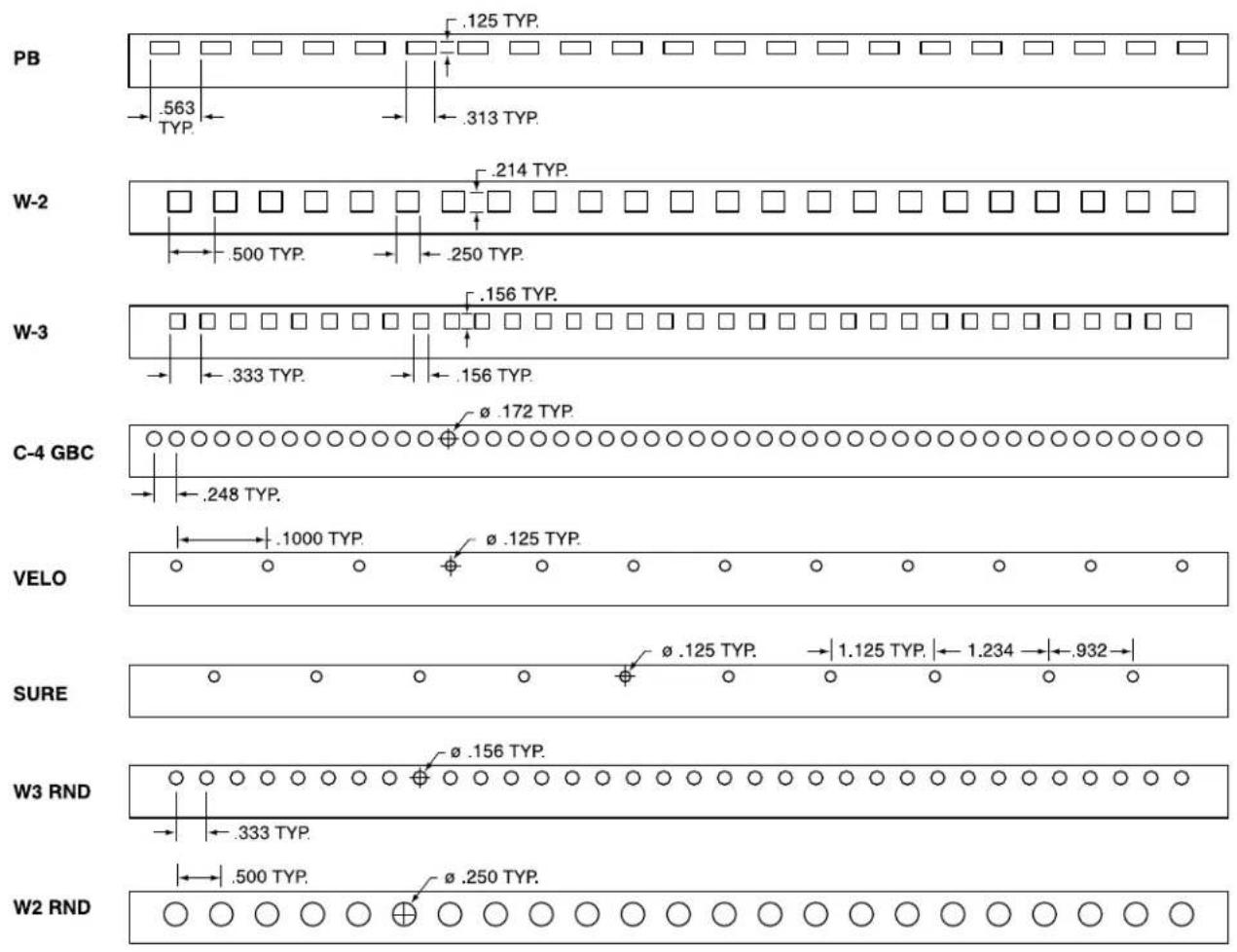
DIE SET PATTERN CHART
other
| Category | Value | | -------- | --------- | | PB | .125 TYP | | W-2 | .214 TYP | | W-3 | .156 TYP | | C-4 GBC | .172 TYP | | VELO | .1000 TYP | | SURE | .125 TYP | | W3 RND | .156 TYP | | W2 RND | .250 TYP |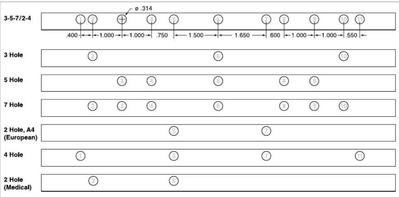
other
| Hole Type | Number of Holes | | :--- | :--- | | 3-5-7/2-4 | 1 | | 3-5-7/2-4 | 2 | | 3-5-7/2-4 | + | | 3-5-7/2-4 | 4 | | 3-5-7/2-4 | 5 | | 3-5-7/2-4 | 6 | | 3-5-7/2-4 | 7 | | 3-5-7/2-4 | 8 | | 3-5-7/2-4 | 9 | | 3-5-7/2-4 | 10 | | 3-5-7/2-4 | 11 | | 3 Hole | .400 | | 3 Hole | 1.000 | | 3 Hole | 1.000 | | 3 Hole | .750 | | 3 Hole | 1.500 | | 3 Hole | 1.650 | | 3 Hole | .600 | | 3 Hole | 1.000 | | 3 Hole | 1.000 | | 3 Hole | .550 | | 5 Hole | ② | | 5 Hole | ⑤ | | 5 Hole | ⑥ | | 5 Hole | ⑧ | | 5 Hole | ⑨ | | 7 Hole | ② | | 7 Hole | ③ | | 7 Hole | ④ | | 7 Hole | ⑥ | | 7 Hole | ⑧ | | 7 Hole | ⑨ | | 7 Hole | ⑩ | | 2 Hole, A4 (European) | | | | | | | | | | | | | | | | | | | | | | | | | | | | | | | | | | | | | | | | | | | | | | | | | | | | | 4 Hole | ① | | 4 Hole | ⑤ | | 4 Hole | ⑦ | | 4 Hole | ⑪ | | 2 Hole (Medical) | ② | | 2 Hole (Medical) | ⑤ | The chart displays the numerical values for each hole type in a table format. The first row contains the number of holes, the second row contains the number of medical holes, and the third row contains the number of medical holes. The values are explicitly labeled on the table above each row.Figure 8
I
RISOLUZIONE DEI PROBLEMI MP2500iX
other
| Category | Dimension (Typ.) | | -------- | ---------------- | | PB | .125 TYP. | | W-2 | .563 TYP. | | W-2 | .313 TYP. | | W-2 | .214 TYP. | | W-2 | .500 TYP. | | W-2 | .250 TYP. | | W-3 | .156 TYP. | | W-3 | .333 TYP. | | C-4 GBC | Ø .172 TYP. | | VELO | .248 TYP. | | VELO | .1000 TYP. | | VELO | Ø .125 TYP. | | SURE | Ø .125 TYP. | | W3 RND | Ø .156 TYP. | | W3 RND | .333 TYP. | | W2 RND | .500 TYP. | | W2 RND | Ø .250 TYP. |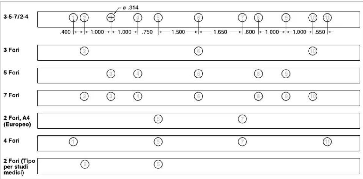
other
| Category | Value | |---|---| | 3-5-7/2-4 | 0.314 | | 3 Fori | 2 | | 3 Fori | 5 | | 5 Fori | 3 | | 5 Fori | 4 | | 5 Fori | 6 | | 5 Fori | 8 | | 5 Fori | 9 | | 7 Fori | 2 | | 7 Fori | 3 | | 7 Fori | 4 | | 7 Fori | 6 | | 7 Fori | 8 | | 7 Fori | 9 | | 7 Fori | 10 | | 2 Fori, A4 (Europeo) | 5 | | 2 Fori, A4 (Europeo) | 7 | | 4 Fori | 1 | | 4 Fori | 5 | | 4 Fori | 7 | | 4 Fori | 10 | | 2 Fori (Tipo per studi medici) | 2 | | 2 Fori (Tipo per studi medici) | 5 |Figure 8
D
other
| Category | Value | | -------- | --------- | | PB | .125 TYP | | W-2 | .214 TYP | | W-3 | .156 TYP | | C-4 GBC | .172 TYP | | VELO | .1000 TYP | | SURE | .125 TYP | | W3 RND | .156 TYP | | W2 RND | .250 TYP |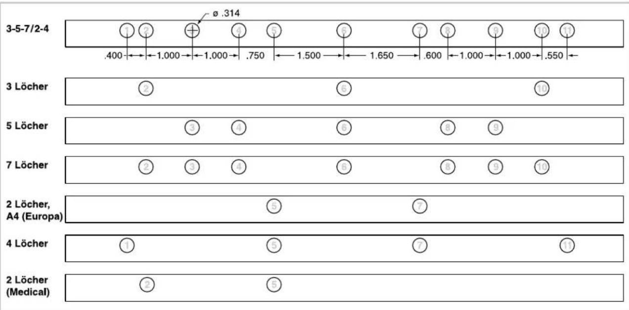
other
| Category | Value | |---|---| | 3-5-7/2-4 | .400 | | 3 Löcher | 2 | | 5 Löcher | 3 | | 7 Löcher | 2 | | 2 Löcher, A4 (Europa) | 5 | | 4 Löcher | 1 | | 2 Löcher (Medical) | 2 | ø .314 ± .750 ± .600 ± .550 ± .750 ± .600 ± .600 ± .600 ± .600 ± .600 ± .600 ± .600 ± .600 ± .600 ± .600 ± .600 ± .600 ± .600 ± .600 ± .600 ± .600 ± .600 ± 1.500 ± 1.650 ± 1.650 ± 1.650 ± 1.650 ± 1.650 ± 1.650 ± 1.650 ± 1.650 ± 1.650 ± 1.650 ± 1.650 ± 1.650 ± 1.650 ± .750 ± .750 ± .750 ± .750 ± .750 ± .750 ± .750 ± .750 ± .750 ± .750 ± .750 ± .750 ± .750 ± .750 ± .750 ± .750 ± .750 + .750 + .750 + .750 + .750 + .750 + .750 + .750 + .750 + .750 + .750 + .750 + .750 + .750 + .750 + .750 + .750 + .75Figure 8
NL
PROBLEMEN OPLOSSEN MP2500iX
other
| Category | Value | | -------- | --------- | | PB | .125 TYP | | W-2 | .214 TYP | | W-3 | .156 TYP | | C-4 GBC | .172 TYP | | VELO | .1000 TYP | | SURE | .125 TYP | | W3 RND | .156 TYP | | W2 RND | .250 TYP |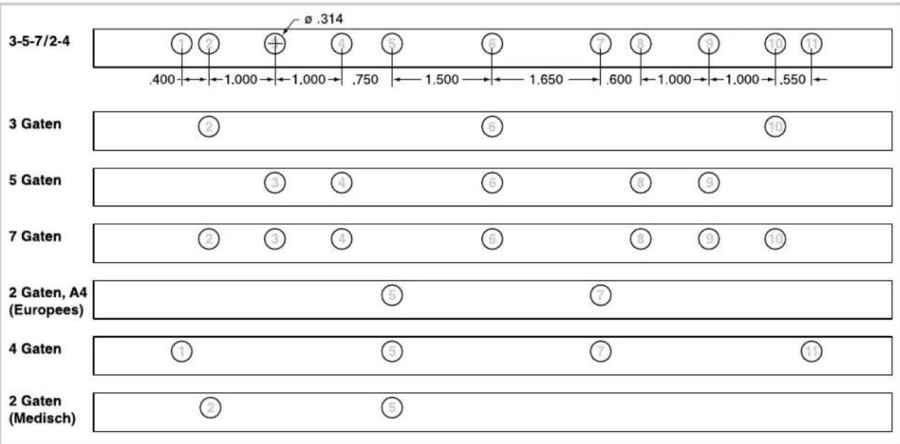
other
| Category | Segment 1 | Segment 2 | Segment 3 | Segment 4 | Segment 5 | Segment 6 | Segment 7 | Segment 8 | Segment 9 | Segment 10 | Segment 11 | |---|---|---|---|---|---|---|---|---|---|---|---| | 3-5-7/2-4 | .400 | 1.000 | 1.000 | .750 | 1.500 | 1.650 | .600 | 1.000 | 1.000 | .550 | | | 3 Gaten | 2 | | | | | 5 | | | | 10 | | | 5 Gaten | | 3 | 4 | | 6 | | 8 | 9 | | | | | 7 Gaten | 2 | 3 | 4 | | 6 | | 8 | 9 | 10 | | | | 2 Gaten, A4 (Europees) | | | | 5 | | 7 | | | | | | | 4 Gaten | 1 | | 5 | | 7 | | 7 | | 13 | | | | 2 Gaten (Medisch) | 2 | | 5 | | | | | | | | |Figure 8
F
other
| Period | Number of Perforations | Time Interval (Time) | | :--- | :--- | :--- | | 3-5-7/2-4 | 1 | .400 - 1.000 | | 3-5-7/2-4 | 2 | 1.000 - 1.000 | | 3-5-7/2-4 | + | .750 - 1.500 | | 3-5-7/2-4 | 4 | 1.650 - 1.650 | | 3-5-7/2-4 | 5 | 1.650 - 1.650 | | 3-5-7/2-4 | 6 | 1.650 - 1.650 | | 3-5-7/2-4 | 7 | .600 - 1.000 | | 3-5-7/2-4 | 8 | 1.000 - 1.000 | | 3-5-7/2-4 | 9 | .550 - | | 3-5-7/2-4 | 10 | | | 3-5-7/2-4 | 11 | | | 3 perforations | 2 | | | 3 perforations | 6 | | | 5 perforations | 3 | 4 | | 5 perforations | 6 | 8 | | 5 perforations | 9 | | | 7 perforations | 2 | 3 | | 7 perforations | 6 | 8 | | 7 perforations | 9 | 10 | | 2 perforations, A4 (européen) | | | | 2 perforations, A4 (européen) | 5 | | | 2 perforations, A4 (européen) | 7 | | | 4 perforations | 1 | | | 4 perforations | 5 | | | 4 perforations | 7 | | | 4 perforations | 13 | | | 2 perforations (médical) | 2 | | | 2 perforations (médical) | 5 | | The chart displays a single data point for 'Ø .314' in the top section. The x-axis is labeled 'Time Interval (Time)'. The y-axis is labeled 'Periods'. The values are estimated based on the 'Time' label at the bottom.Figure 8
E
General Binding Corporation
Northbrook, IL 60062-4195
http://www.gbccconnect.com


- GBC Modular Series Punch
- SAFETY MESSAGES AVVERTENZE PER LA SICUREZZA SICHERHEITSHINWEISE
- CAUTION: IN CASE OF EMERGENCY, USE THE POWER CORD AS A MAIN DISCONNECT DEVICE!
- (LE NOTE CHE SEGUONO PERTENGONO SOLO ALLE MACCHINE ALIMENTATE A 115 V 60 HZ.)
- DISIMBALLO E MESSA A PUNTO
- I
- D
- NL
- F
- E
- PUNCHING
- PERFORAZIONE
- SOSTITUZIONE DEGLI STAMPI INTERCAMBIABILI
- |
- For Standard Sheet Sizes:
- Step 3: Insert Paper Into
- Step 4: Punch the Paper:
- Step 5: Check Edge Guide
- Removing Punch Pins:
Brand : GBC
Model : MP2500iX
Category : Binder