TRS 520 - Waste press TEKA - Free user manual and instructions
Find the device manual for free TRS 520 TEKA in PDF.

User questions about TRS 520 TEKA
0 question about this device. Answer the ones you know or ask your own.
Ask a new question about this device
Download the instructions for your Waste press in PDF format for free! Find your manual TRS 520 - TEKA and take your electronic device back in hand. On this page are published all the documents necessary for the use of your device. TRS 520 by TEKA.
USER MANUAL TRS 520 TEKA
natural_image
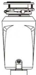
Technical line drawing of a mechanical device with no visible text or symbolsFood waste disposer
Küchenabfallentsorger
Triturador de desperdicios de comida
Triturador de residuos alimentares
Broyeur de déchets alimentaires
Matavfallshanterare
Drtič potravinového odpadu
Rozdrabniacz odpadów spożywczych
утализация пшевых отходов
Yemek auğı
TRS 520
COD. 115890042
Made In CHINA
220-240V
50/60HZ
380 W

VOL.: 0.0223 m3
MODELS: TRS 520
This Food Waste Disposer has been designed to operate on 220-240 Volt, 50-60 Hz exclusively. Using any other voltage or Hz adversely affects performance.
natural_image
Line drawing of a mechanical device with a cylindrical top and base (no text or symbols)Food waste disposer
Küchenabfallentsorger
Triturador de desperdicios de comida
Triturador de residuos alimentares
Broyeur de déchets alimentaires
Matavfallshanterare
Drtič potravinového odpadu
Rozdrabniacz odpadów spożywczych
уптипзация пшцевых отходов
Yemek atığı
TRS 520
COD. 115890043
Made In CHINA
120V
60HZ
380 W
4.5 A

US LISTED
WASTE DISPOSER (E476056)
VOL.: 0.0223 m3

MODEL: TRS 520
This Food Waste Disposer has been designed to operate on 110-120 Volt, 60 Hz exclusively. Using any other voltage or Hz adversely affects performance.
IMPORTANT: Read all instructions thoroughly. Keep this guide for future reference.
CAUTION: Be sure to review SAFETY INSTRUCTIONS FIRST PERTAINING TO A RISK OF FIRE, ELECTRICAL SHOCK OR INJURY TO PERSONS before using disposer.
Record important disposer information here
Model Number\* Serial Number\*
*Above information appears on the label affixed to bottom of the disposer. For your convenience, write down the model and serial number prior to installation.
Proof of purchase is required for Warranty. Staple receipt or proof of purchase to this manual for easy reference. Warranty is non-transferable.
INSTRUCTIONS PERTAINING TO A RISK OF FIRE, ELECTRIC SHOCK OR INJURY TO PERSONS. SAVE THESE INSTRUCTIONS.
WARNING - When using electrical appliances, basic precautions should always be followed, including the following:
- Read all instructions before using the appliance.
- To reduce the risk of injury, close supervision is necessary when an appliance is used near children.
- Do not put fingers or hands into a waste disposer.
- Turn the power switch to the off position or unplug the appliance before attempting to clear a jam or remove an object from the disposer.
- When attempting to loosen a jam in a waste disposer, use a long wooden object such as a wooden spoon or the wooden handle of a broom or mop.
- When attempting to remove objects from a waste disposer use long-handled tongs or pliers. If the disposer is magnetically actuated, non-magnetic tools should be used.
- To reduce the risk of injury by materials that may be expelled by a waste disposer, do not put the following into a disposer: clam or oyster shells; caustic drain cleaners or similar products; glass, china or plastic; large whole bones; metal, such as bottle caps, tin cans, aluminum foil or utensils; hot grease or other hot liquids; whole corn-husks.
- When not operating a disposer, leave the stopper in
place to reduce the risk of objects falling into the disposer.
- DO NOT operate disposer unless splash guard is in place.
- For proper grounding instructions see the ELECTRICAL CONNECTIONS portion of this manual.
- The appliance must be installed so that reset buttons and reversing switches are readily accessible.
- This appliance is not intended for use by persons (including children) with reduced physical, sensory or mental capabilities, or lack of experience and knowledge, unless they have been given supervision or instruction concerning use of the appliance by a person responsible for their safety. Children should be supervised to ensure that they do not play with the appliance.
- If the supply cord is damaged, it must be replaced by the manufacturer, its service agent or similarly qualified persons in order to avoid a hazard.
- At least 6L/min of water flow is required to operate the appliance.
The receptacle to which this appliance is connected must be controlled by a switch.
TYPICAL INSTRUCTIONS, YOUR MODEL MAY VARY.
Before starting this step, turn off electrical power at the circuit breaker or fuse box. Unplug disposer.
If your old mount is the same type as the mount on your new disposer, just reverse the assembly instructions found in section 3. If your new mount system is different, follow these instructions:
A. Have a container available to catch any excess water / waste from current disposer.
B. Use a pipe wrench to disconnect drain line where it attaches to disposer discharge elbow (see 1A).
C. Remove disposer from sink flange by turning mount ring to the left clockwise (see 1B). If you are unable to turn the mount ring, tap on one of the extensions from the ring with a hammer. Some mounting systems have tubular extensions. Inserting a screwdriver into one tube will provide additional leverage for turning the mount ring (see 1B). Some disposers may require the removal or loosening of nuts from the mount screws (see 1C). Some disposers may require the removal of a clamp.
Caution: Be sure to support the disposer while performing this step or it may fall when the mounting ring is disconnected from the mounting assembly.
D. To remove remaining mount system from the sink, loosen mount screws, push mount ring up. Under it is the snap ring. Use screwdriver to pop off ring (see 1D). Remove mount ring, protector ring and gasket from sink flange. Some mounts will require the unscrewing of a large ring holding the sink flange in place. Pull sink flange up through sink and clean off old putty from sink.
E. Ensure that sink is clean and thoroughly dry.
IMPORTANT: This is a good time to clean out the trap and drain lines by running a drain auger or plumber's snake before installing your new disposer.
1A
1B
1C
1D
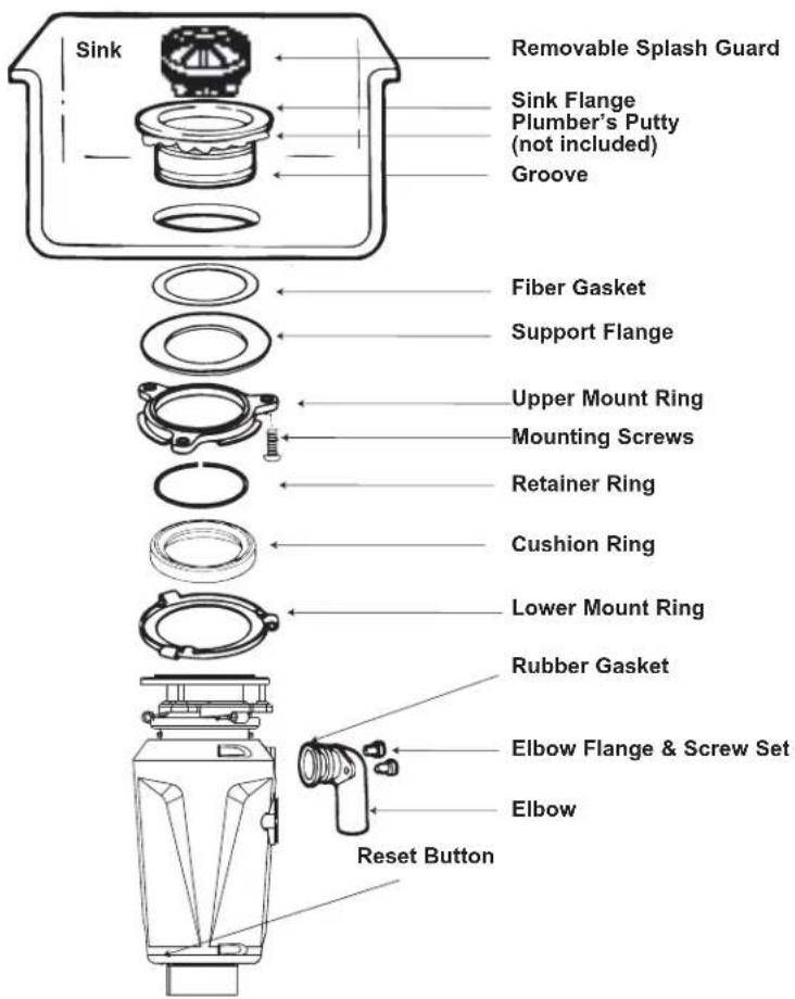
2. INSTALLATION OF MOUNTING ASSEMBLY
A

STOPPER
B

REMOVABLE SPLASH GUARD
C
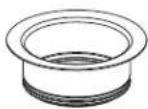
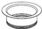
SINK FLANGE
D
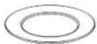
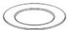
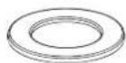
FIBER GASKET
E

SUPPORT FLANGE
F
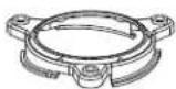
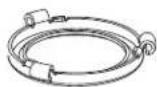
UPPER MOUNT RING
G

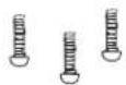
MOUNT SCREWS
H
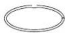
RETAINER RING
|
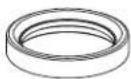
CUSHION RING*
J
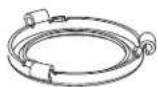
LOWER MOUNT RING*
READ CAREFULLY AND COMPLETELY BEFORE STARTING NOTE: As the mounting assembly is properly assembled at the factory, please pay close attention to the order of the mounting system parts.
NOTE: Cushion Ring included between the Upper Mount Ring and Lower Mounting Ring.
* Part not disengaged during disposer installation.
(2. CONTINUED) INSTALLATION OF MOUNTING ASSEMBLY
A. The Cushion Ring and the Lower Mount Ring will remain attached to the disposer during installation.
Take apart the other parts of the mounting assembly by rotating the Lower Mount Ring (J on page 3) clockwise until the Lower Mount Ring Tabs slide off from the Upper Mount Ring ramp (A1). This allows you to pull the Sink Flange up and out of the remaining Lower Mount Assembly. Note the order of these parts as they are arranged in the required order. Unscrew the 3 Mount Screws until the Upper Mount Ring can be moved to the top of the Support Flange. Remove the Retainer Ring with a flat head screw driver.(A2)
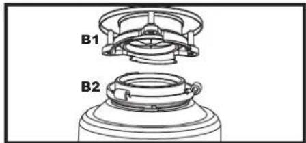
B. Keep the remaining parts placed together in the order they were removed (B1). Before you connect the disposer to the mount assembly under the sink, make sure the Lower Mount Ring is in place and the black Cushion Ring is still engaged properly to the top of the disposer hopper (B2).
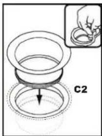
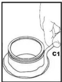
C. Be sure the sink is clean. Load the underside rim of the sink flange with plumber's putty (C1). From top of the sink, push the sink flange down against the sink opening to make a good seal (C2). DO NOT MOVE OR ROTATE the sink flange once it has been seated or the seal may be broken.
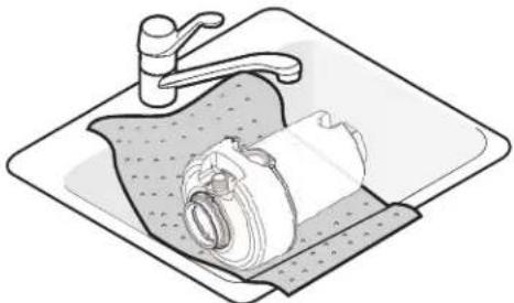
D Place a heavy object, such as the disposer (use a towel to prevent sink scratching) on top of the Sink Flange to hold it down.
natural_image
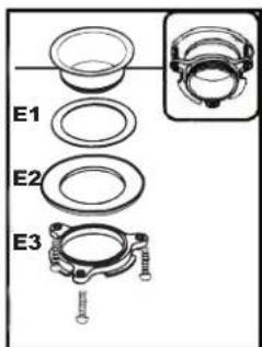
Line drawing of a washing machine on a sink with a faucet (no text or symbols)E. Take the remaining portion of the mount assembly, that was put aside. From under the sink insert the Fiber Gasket (E1), then the Support Flange (E2), and then the Upper Mount Ring (E3).
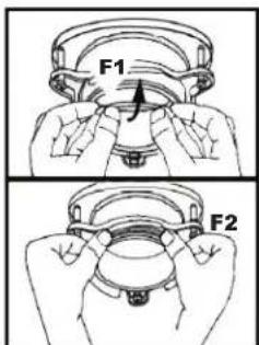
F. Hold the three parts in place while attaching the Retainer Ring (F1) by pulling it apart and having it snap within the groove of the sink flange (F2).
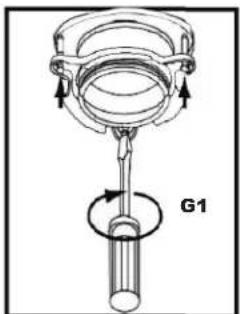
G. Tighten the three Mount Screws evenly and firmly against the Support Flange (G1). Do not over tighten.
H. Trim off any excess plumber's putty in the sink with a plastic knife or something similar that will not damage your sink.

natural_image
Simple line drawing of a hand holding a cylindrical object with a base, labeled C1 (no text or symbols on the object itself)


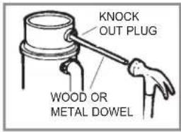
3. DISHWASHER CONNECTION PREPARATION
If you are utilizing a dishwasher, complete the following procedure.
Using a blunt instrument (steel punch or wooden dowel), knock out entire plug. Do not use a screwdriver or sharp instrument. (When knockout plug falls into disposer, you may remove it or grind it up when the disposer is used. This will not damage the disposer in any way, but it may take some time to grind).
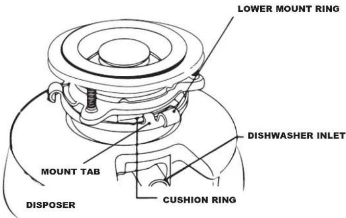
4. LOCKING MOUNTING ASSEMBLY DETAIL
Attach disposer onto the Upper Mount Ring by aligning the three mount tabs on the Lower Mount Ring with the slide-up Ramps on the Upper Mount Ring and rotating counter clockwise. See Below.
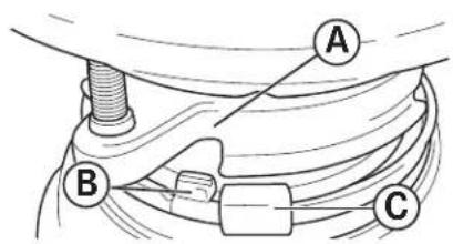
The lower mounting ring (which is part of the disposer) has 3 tabs that grab the mounting ring ramp.
(A) points to the Upper Mount Ring.
(B) is the tab that slides up onto the "Ramp".
(C) is the "Ear" that is used to help rotate the Lower Mount Ring. Use a screwdriver for leverage if needed.
natural_image
Diagram of a boat navigating water with a circular marker labeled 'D' (no text or symbols beyond the label)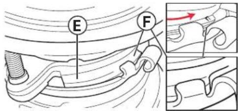
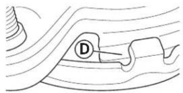
Lift and turn the Lower Mount Ring counter clockwise until all three mount tabs lock over the Ridges (F) on the slide-up Ramps (D) of the Upper Mount Ring.
As the Lower Mount Ring is turned counter clockwise each tab slides up onto the Upper Mount Ring Ramp (E) and locks in position over the Ridges (F).
Use a screwdriver or hammer for leverage if needed.
If a disposer needs to be removed, tapping on the Ear clockwise with a hammer will easily loosen the Lower Mount Ring.
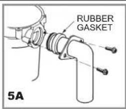
5. DISCHARGE ELBOW & DISHWASHER CONNECTIONS
A. Connect the waste elbow to the disposer by sliding the flange against the rubber gasket on the elbow and tightening the screws into the disposer (see 5A). Then connect bottom of the elbow by tightening the slip nut (see 5B). If using a straight pipe, it must have a lip similar to the one on the elbow. Remove the gasket from the elbow and install it on the straight pipe with the flat end of the gasket facing toward the disposer discharge opening. IF YOU ARE NOT CONNECTING TO A DISHWASHER make sure all plumbing connections are tight and in accordance with all plumbing codes and ordinances. Run water and check for leaks. Go on to Step 6.
B. Connect dishwasher hose (see 5C) using hose clamp. Make sure all plumbing connections are tight and in accordance with all plumbing codes and ordinances. Run water and check for leaks.
natural_image
Illustration of a hand using a tool to tie a rope around a curved pipe (no text or symbols)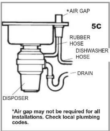
6. ELECTRICAL CONNECTIONS
A. Connect disposer to appropriate household current only.
The receptacle to which this appliance is connected must be controlled by a switch.
WARNING: IMPROPER CONNECTION OF THE EQUIPMENT GROUNDING CONDUCTOR CAN RESULT IN A RISK OF ELECTRIC SHOCK. CHECK WITH A QUALIFIED ELECTRICIAN OR SERVICEMAN IF YOU ARE IN DOUBT AS TO WHETHER THE APPLIANCE IS PROPERLY GROUNDED. DO NOT MODIFY THE PLUG PROVIDED WITH THE APPLIANCE IF IT WILL NOT FIT THE OUTLET. HAVE A PROPER OUTLET INSTALLED BY A QUALIFIED ELECTRICIAN.
GROUNDING INSTRUCTIONS
FOR WASTE DISPOSERS EQUIPPED WITH A GROUNDED PLUG-IN POWER CORD.
B. This appliance must be grounded. In the event of a malfunction or breakdown, grounding provides a path of least resistance for electric current to reduce the risk of electric shock. This appliance is equipped with a cord having an equipment-grounding conductor
and a grounding plug. The plug must be plugged into an appropriate outlet that is properly installed and grounded in accordance with all local codes and ordinances. If the supply cord is damaged it must be replaced by the manufacturer, its service agent or similarly qualified person in order to avoid a hazard.
7. OPERATING INSTRUCTIONS
The Anti-Jam Swivel Impellers make a clicking sound as they initially swing into place. This indicates normal operation.
A. Remove sink stopper. Turn on a medium flow of cold water.
B. Turn switch to ON position; your motor is turning at full speed and ready to use.
C. Scrape in food waste. Down the drain go table scraps, peelings, rinds, seeds, pits, small bones and coffee grounds. To speed up food waste disposal, cut or break up large bones, rinds and cobs. Large bones and fibrous waste require considerable grinding time
and are more easily thrown away with other trash. Do not be alarmed that the disposer slows down while grinding. The disposer is actually increasing torque (grinding power) and is operating under normal conditions.
D. Before turning disposer off, let water and disposer run for approximately 15 seconds after shredding or grinding stops. This assures that all waste is thoroughly flushed through trap and drain.
E. It is not recommended to use hot water while running disposer. Cold water will keep waste and fats solid so disposer can flush away particles.
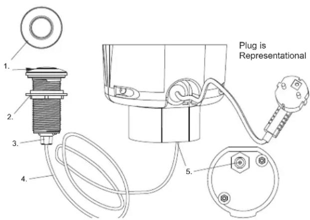
AIR SWITCH OPERATED
Disposer Air Switch Assembly
The Actuator which consists of:
- Actuator Button
- Actuator Nut
- Actuator Outlet (Threaded portion)
The Air Switch Sensor Enclosure which is installed into the disposer. Only the air tube nozzle is visible from the outside of the disposer.
Air Tube Assembly which consists of:
- Air Tube-Clear or black
- Air Tube Nut/Sensor Inlet
Installation And Operating Instructions
A. If a hole does not already exist - drill a hole of 35mm to 40mm into the sink or countertop where the Actuator Button (#1) is to be placed.
B. Insert, from the top, the Actuator Outlet through the drilled hole.
C. Thread the Actuator Nut (#2) onto the Actuator Outlet (#3) and tighten firmly by hand.
D. Firmly connect Air Tube (#4): one side to Actuator
Outlet (#3) and one side to Sensor Inlet (#5)
E. Plug Disposer Power Cord into main electrical service.
F. To turn on disposer, press Actuator Button (#1). To turn off, press Actuator Button again.
8. CLEANING AND MAINTENANCE
DO NOT ATTEMPT TO LUBRICATE YOUR DISPOSER!
The motor is permanently lubricated. The disposer is self cleaning and scours its internal parts with each use.
NEVER put lye or chemical drain cleaners into the disposer, as they cause serious corrosion of metal parts. If used, resulting damage can be easily detected and all
warranties are void. Mineral deposits from your water can form on the stainless steel turntable, giving the appearance of rust. DO NOT BE ALARMED, the stainless steel turntables used will not corrode.
9. TROUBLESHOOTING
Before seeking repair or replacement, we recommend that you review the following:
LOUD NOISES: (Other than those during grinding of small bones and fruit pits): These are usually caused by accidental entry of a spoon, bottle cap or other foreign object. To correct this, turn off electrical switch and water. After disposer has stopped, remove splash guard, remove object with long handled tongs, and replace splash guard.
UNIT DOES NOT START: Unplug power cord or turn either the wall switch or breaker box switch to "OFF" position, depending on your model and wiring configuration. Remove stopper and/or splash guard. Check to see if turntable will rotate freely using a wooden broom handle. If turntable rotates freely, replace splash guard and check reset button to see if it has been tripped. Reset button is red and located on the front of the disposer. Push button in until it clicks and remains depressed.
If reset button has not been tripped, check for shorted or broken wire connecting to disposer. Check electrical power switch, fuse box or circuit breaker. If wiring and electrical components are intact, the unit may have internal problems that require service or replacement.
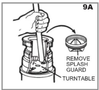
IF TURNTABLE DOES NOT ROTATE FREELY: Turn off disposer, then check for any foreign object lodged between the turntable and grind ring. Dislodge object by rotating table with a wooden broom handle (see 9A) and remove object. If no foreign object is present, there may be internal problems.
LEAKS: If the unit leaks at the top, it may be due to:
- Improper seating of sink flange (gasket centering, putty or tightening).
- Support ring not tightened properly.
- Defective or improperly installed cushion mount.
If unit leaks at the waste elbow, leak may be due to improper tightening of elbow flange screws.
natural_image
Technical line drawing of a mechanical device with no visible text or symbolsTriturador de desechos de alimentos Küchenabfallentsorger
natural_image
Line drawing of a cylindrical mechanical device with a central hub and top component (no text or symbols)natural_image
Illustration of a hand using a tool to tie a U-shaped pipe knot (no text or symbols)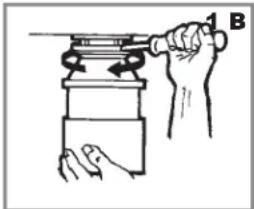
natural_image
Illustration of a hand using a tool to press or install a mechanical component (no text or symbols visible)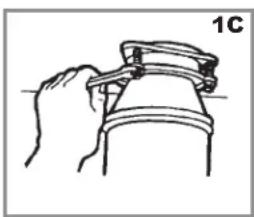
natural_image
Hand holding a mechanical clamp or bracket, no text or symbols visible
natural_image
Line drawing of two hands holding a magnifying glass over a horizontal line (no text or symbols)natural_image
Illustration of a washing machine on a square sink (no text or symbols)natural_image
Simple line drawing of a hand holding a cylindrical object with a base, labeled C1 (no text or symbols on the object itself)


natural_image
Diagram of a pipe or pipe system with wavy lines and a labeled component (D), no readable text or symbols present.natural_image
Line drawing of a mechanical device with a central handle and mounting base (no text or symbols)Food waste disposer
Küchenabfallentsorger
Triturador de residuos alimentares
Broyeur de déchets alimentaires
Matavfallshanterare
Drtič potravinového odpadu
Rozdrabniacz odpadów spożywczych
уптплзация пшцевых отходов
Yemek atığı
natural_image
Line drawing of a mechanical device with no visible text or symbolsFood waste disposer
Küchenabfallentsorger
Triturador de desperdicios de comida
Triturador de residuos alimentares
Broyeur de déchets alimentaires
Matavfallshanterare
Drtič potravinového odpadu
Rozdrabniacz odpadów spożywczych
уптипзация пшцевых отходов
Yemek atığı
TRS 520
COD. 115890043
Fabriqué en CHINE
120V
60HZ
380 W
4.5 A

BROYEUR DE
DÉCHETS
RECONNO AUX ETATS-UNIS (E476056)
VOLUME : 0,0223 m3

MODÈLE : TRS 520
natural_image
Illustration of a hand using a tool to tie a U-shaped pipe knot (no text or symbols)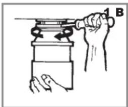
natural_image
Illustration of a hand using a tool to lift a cylindrical object, no text or symbols present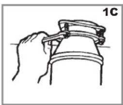
natural_image
Hand holding a mechanical clamp or bracket, no text or symbols visible
natural_image
Line drawing of two hands holding a magnifying glass over a horizontal line (no text or symbols)2. INSTALLATION DE LA PLAQUE DE FIXATION
A

BOUCHON
B

PROTECTON ANTI- ÉCLABOUSSURES AMOVIBLE
C
COLLET D'ÉVIER
D
JOINT D'ÉTANCHÉITÉ EN FIBRE
E
BAGUE DE MONTAGE
F

BAGUE DE MONTAGE SUPÉRIEURE
G
VIS DE FIXATION
H
BAGUE DE RETENUE
|

ANNEAU COUSSINET*
J
BAGUE DE MONTAGE INFÉRIEURE*
VEUILLEZ LIRE ATTENTIVEMENT ET COMPLÈTEMENT AVANT DE DÉBUTER
natural_image
Illustration of a washing machine inside a square basin with a faucet (no text or symbols)natural_image
Simple line drawing of a hand holding a cylindrical object with a base, labeled C1 (no text or symbols on the object itself)