DCPS151 - Drill DEWALT - Free user manual and instructions
Find the device manual for free DCPS151 DEWALT in PDF.

User questions about DCPS151 DEWALT
0 question about this device. Answer the ones you know or ask your own.
Ask a new question about this device
Download the instructions for your Drill in PDF format for free! Find your manual DCPS151 - DEWALT and take your electronic device back in hand. On this page are published all the documents necessary for the use of your device. DCPS151 by DEWALT.
USER MANUAL DCPS151 DEWALT
DEWALT POWERSHIFT® 6.375IN Core Drill Stand
natural_image
Technical line drawing of a BEVA electric vehicle chassis with mounting base and wheels (no text or symbols)| English (original instructions) | 8 |
| Français (traduction de la notice d'instructions originale) | 18 |
| Español (traducido de las instrucciones originales) | 30 |
Carriage
2 Carriage lock
3 Vacuum base pressure gauge
4 Feed handle
5 Drill holder
6 Column
7 Angle drilling scale
8 Base
9 Removable wheels
10 Bubble level for vertical applications
11 Bubble level for horizontal applications
12 Friction knob
13 Drilling depth scale
14 Stabilizer bolts
15 Hose connection
16 Battery connection
17 Ratchet handle for angular coring
18 Drill lock/unlock nozzle
19 Drill lock/unlock slot
20 Carriage up and down slot
21 Core bit centering piece
22 Driving cap
text_image
Technical diagram of a mechanical assembly with numbered components for identification and assembly reference.Fig. A2
23 Fastening set for concrete
24 Fastening set for masonry
25 Rubber seal
other
| Category | Charge (%) | |---|---| | 76-100% charged | | | Chargé de 76-100 % | | | 76-100% cargada | | | 51-75% charged | | | Chargé de 51-75 % | | | 51-75% cargada | | | 26-50% charged | | | Chargé de 26-50% | | | 26-50% cargada | | | 16-25% charged | | | Chargé de 16-25% | | | 16-25% cargada | | | 0-15% charged | | | Chargé de 0-15% | | | 0-15% cargada | |Fig. C
text_image
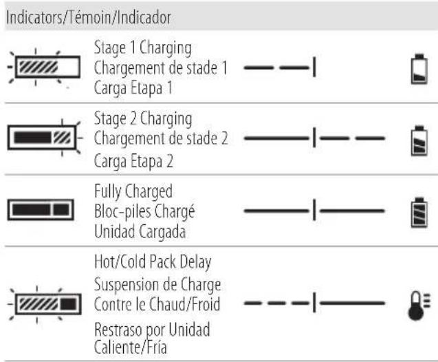
Indicators/Témoin/Indicador Stage 1 Charging Chargement de stade 1 Carga Etapa 1 Stage 2 Charging Chargement de stade 2 Carga Etapa 2 Fully Charged Bloc-piles Chargé Unidad Cargada Hot/Cold Pack Delay Suspension de Charge Contre le Chaud/Froid Restraso por Unidad Caliente/FriaFig. D
text_image
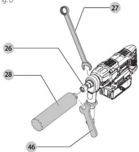
26 27 28 46Fig. E
natural_image
Technical line drawing of a mechanical assembly with pipes and gears (no text or symbols)Fig. F

text_image
Technical diagram showing mechanical assembly with labeled component '5'Fig. G
text_image
40 41 42 43Fig. H
natural_image
Technical line drawing of an automotive chassis with battery pack and suspension components (no text or symbols)Fig.1
natural_image
Technical line drawing of a mechanical device mounted on a brick wall, no text or symbols presentFig. J1
text_image
Fig. J1 28 DEWALR 30 31Fig. J2
text_image
31 30 29Fig. K
text_image
32 25 25Fig. L
text_image
3 50 35Fig. M
text_image
Technical diagram of a vehicle chassis with numbered components and labeled partsFig. N
text_image
44Fig. O
natural_image
Technical line drawing of a mechanical assembly with gears and rollers (no text or symbols)Fig. P
natural_image
Technical line drawing of a mechanical assembly with no visible text or symbolsFig. Q Fig. R
text_image
Fig. Q Fig. R 20 4 4 37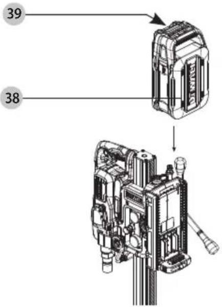
text_image
39 38Fig. S
text_image
45 1 2Fig. T
natural_image
Technical line drawing of a mechanical device with no visible text or symbolsFig. U

text_image
48 47 49English

WARNING: Read all safety warnings, instructions, illustrations, and specifications in this manual, including the battery and charger sections provided in an original tool manual or the separate Batteries and Chargers manual. Manuals
can be obtained by contacting Customer Service as described elsewhere in this manual. Failure to follow the warnings and instructions may result in electric shock, fire and/or serious injury.
Definitions: Safety Alert Symbols and Words
This instruction manual uses the following safety alert symbols and words to alert you to hazardous situations and your risk of personal injury or property damage.
RANGER: Indicates an imminently hazardous situation which, if not avoided, will result in death or serious injury.
WARNING: Indicates a potentially hazardous situation which, if not avoided, could result in death or serious injury.
NAUTION: Indicates a potentially hazardous situation which, if not avoided, may result in minor or moderate injury.
(Used without word) Indicates a safety related message. NOTICE: Indicates a practice not related to personal injury which, if not avoided, may result in property damage.
Intended Use
Your DCPS151 DEWALT POWERSHIFT® 6.375IN core drill stand has been designed to extend the capabilities of your DEWALT DCD150 60V MAX 3-Speed Core Drill. The stand enables set up in both downward vertical and horizontal applications. Establishing angles ranging from -15° to 45°, the stand can also be used in slope applications.
GENERAL POWER TOOL SAFETY WARNINGS
WARNING: Read all safety warnings, instructions, illustrations and specifications provided with this power tool. Failure to follow all instructions listed below may result in electric shock, fire and/or serious injury.
SAVE ALL WARNINGS AND INSTRUCTIONS FOR FUTURE REFERENCE.
The term "power tool" in the warnings refers to your mains-operated (corded) power tool or battery-operated (cordless) power tool.
1) Work Area Safety
a) Keep work area clean and well lit. Cluttered or dark areas invite accidents.
b) Do not operate power tools in explosive atmospheres, such as in the presence of flammable liquids, gases or dust. Power tools create sparks which may ignite the dust or fumes.
c) Keep children and bystanders away while operating a power tool. Distractions can cause you to lose control.
2) Electrical Safety
a) Power tool plugs must match the outlet. Never modify the plug in any way. Do not use any adapter plugs with earthed (grounded) power tools. Unmodified plugs and matching outlets will reduce risk of electric shock.
b) Avoid body contact with earthed or grounded surfaces, such as pipes, radiators, ranges and refrigerators. There is an increased risk of electric shock if your body is earthed or grounded.
c) Do not expose power tools to rain or wet conditions.
Water entering a power tool will increase the risk of electric shock.
d) Do not abuse the cord. Never use the cord for carrying, pulling or unplugging the power tool. Keep cord away from heat, oil, sharp edges or moving parts.
Damaged or entangled cords increase the risk of electric shock.
e) When operating a power tool outdoors, use an extension cord suitable for outdoor use. Use of a cord suitable for outdoor use reduces the risk of electric shock.
f) If operating a power tool in a damp location is unavoidable, use a ground fault circuit interrupter (GFCI) protected supply. Use of a GFCI reduces the risk of electric shock.
3) Personal Safety
a) Stay alert, watch what you are doing and use common sense when operating a power tool. Do not use a power tool while you are tired or under the influence of drugs, alcohol or medication. A moment of inattention while operating power tools may result in serious personal injury.
b) Use personal protective equipment. Always wear eye protection. Protective equipment such as a dust mask, non-skid safety shoes, hard hat, or hearing protection used for appropriate conditions will reduce personal injuries.
c) Prevent unintentional starting. Ensure the switch is in the off position before connecting to power source and/or battery pack, picking up or carrying the tool. Carrying power tools with your finger on the switch or energizing power tools that have the switch on invites accidents.
d) Remove any adjusting key or wrench before turning the power tool on. A wrench or a key left attached to a rotating part of the power tool may result in personal injury.
e) Do not overreach. Keep proper footing and balance at all times. This enables better control of the power tool in unexpected situations.
f) Dress properly. Do not wear loose clothing or jewelry. Keep your hair, clothing and gloves away from moving parts. Loose clothes, jewelry or long hair can be caught in moving parts.
g) If devices are provided for the connection of dust extraction and collection facilities, ensure these are connected and properly used. Use of dust collection can reduce dust-related hazards.
h) Do not let familiarity gained from frequent use of tools allow you to become complacent and ignore tool safety principles. A careless action can cause severe injury within a fraction of a second.
4) Power Tool Use and Care
a) Do not force the power tool. Use the correct power tool for your application. The correct power tool will do the job better and safer at the rate for which it was designed.
b) Do not use the power tool if the switch does not turn it on and off. Any power tool that cannot be controlled with the switch is dangerous and must be repaired.
c) Disconnect the plug from the power source and/or remove the battery pack, if detachable, from the power tool before making any adjustments, changing accessories, or storing power tools. Such preventive safety measures reduce the risk of starting the power tool accidentally.
d) Store idle power tools out of the reach of children and do not allow persons unfamiliar with the power tool or these instructions to operate the power tool. Power tools are dangerous in the hands of untrained users.
e) Maintain power tools and accessories. Check for misalignment or binding of moving parts, breakage of parts and any other condition that may affect the power tool's operation. If damaged, have the power tool repaired before use. Many accidents are caused by poorly maintained power tools.
f) Keep cutting tools sharp and clean. Properly maintained cutting tools with sharp cutting edges are less likely to bind and are easier to control.
g) Use the power tool, accessories and tool bits, etc. in accordance with these instructions, taking into account the working conditions and the work to be performed.
Use of the power tool for operations different from those intended could result in a hazardous situation.
h) Keep handles and grasping surfaces dry, clean and free from oil and grease. Slippery handles and grasping surfaces do not allow for safe handling and control of the tool in unexpected situations.
5) Battery Tool Use and Care
a) Recharge only with the charger specified by the manufacturer. A charger that is suitable for one type of battery pack may create a risk of fire when used with another battery pack.
b) Use power tools only with specifically designated battery packs. Use of any other battery packs may create a risk of injury and fire.
c) When battery pack is not in use, keep it away from other metal objects, like paper clips, coins, keys, nails, screws or other small metal objects, that can make a connection from one terminal to another. Shorting the battery terminals together may cause burns or a fire.
d) Under abusive conditions, liquid may be ejected from the battery; avoid contact. If contact accidentally occurs, flush with water. If liquid contacts eyes, additionally seek medical help. Liquid ejected from the battery may cause irritation or burns.
e) Do not use a battery pack or tool that is damaged or modified. Damaged or modified batteries may exhibit unpredictable behavior resulting in fire, explosion or risk of injury.
f) Do not expose a battery pack or tool to fire or excessive temperature. Exposure to fire or temperature above 265 °F (130 °C) may cause explosion.
g) Follow all charging instructions and do not charge the battery pack or tool outside the temperature range specified in the instructions. Charging improperly or at temperatures outside the specified range may damage the battery and increase the risk of fire.
6) Service
a) Have your power tool serviced by a qualified repair person using only identical replacement parts. This will ensure that the safety of the power tool is maintained.
b) Never service damaged battery packs. Service of battery packs should only be performed by the manufacturer or authorized service providers.
Safety Instructions for All Operations
- Wear ear protectors. Exposure to noise can cause hearing loss.
- Use the auxiliary handle(s) supplied with the tool. Loss of control can cause personal injury.
- Brace the tool properly before use. This tool produces a high output torque and without properly bracing the tool during operation, loss of control may occur resulting in personal injury.
- Hold the power tool by insulated gripping surfaces when performing an operation where the cutting accessory may contact hidden wiring or its own cord. Cutting accessory contacting a "live" wire may make exposed metal parts of the tool "live" and could give the operator an electric shock.
Safety Instructions When Using Long Drill Bits
- Never operate at higher speed than the maximum speed rating of the drill bit. At higher speeds, the bit is likely to bend if allowed to rotate freely without contacting the workpiece, resulting in personal injury.
- Always start drilling at low speed and with the bit tip in contact with the workpiece. At higher speeds, the bit is likely to bend if allowed to rotate freely without contacting the workpiece, resulting in personal injury.
- Apply pressure only in direct line with the bit and do not apply excessive pressure. Bits can bend causing breakage or loss of control, resulting in personal injury.
Diamond Drill Safety Warnings
a) When performing drilling that requires the use of water, route the water away from the operator's work area or use a liquid collection device. Such precautionary measures keep the operator's work area dry and reduce the risk of electrical shock.
b) Operate power tool by insulated grasping surfaces, when performing an operation where the cutting accessory may contact hidden wiring or its own cord. Cutting accessory contacting a "live" wire may make exposed metal parts of the power tool "live" and could give the operator an electric shock.
c) Wear hearing protection when diamond drilling. Exposure to noise can cause hearing loss.
d) When the bit is jammed, stop applying downward pressure and turn off the tool. Investigate and take corrective actions to eliminate the cause of the bit jamming.
e) When restarting a diamond drill in the workpiece check that the bit rotates freely before starting. If the bit is jammed, it may not start, may overload the tool, or may cause the diamond drill to release from the workpiece.
f) When securing the drill stand with anchors and fasteners to the workpiece, ensure that the anchoring used is capable of holding and restraining the machine during use. If the workpiece is weak or porous, the anchor may pull out causing the drill stand to release from the workpiece.
g) When securing the drill stand with a vacuum pad to the workpiece, install the pad on a smooth, clean, non-porous surface. Do not secure to laminated surfaces such as tiles and composite coating. If the workpiece is not smooth, flat or well affixed, the pad may pull away from the workpiece.
h) Ensure there is sufficient vacuum before and during drilling. If the vacuum is insufficient, the pad may release from the workpiece.
English
i) Never perform drilling with the machine secured by the vacuum pad only, except when drilling downwards. If the vacuum is lost, the pad will release from the workpiece.
j) When drilling through walls or ceilings, ensure to protect persons and the work area on the other side. The bit may extend through the hole or the core may fall out on the other side.
k) Do not use this tool for overhead drilling with water supply. Water entering the power tool will increase the risk of electric shock.
- Wear safety goggles or other eye protection. Drilling operations cause chips to fly. Flying particles can cause permanent eye damage.
- Bits, tools and drilling area get hot during operation. Wear gloves when touching them.
- Use the core drill under constant supervision.
- Make sure not to cut through electric mains, gas or water pipes. Use detection systems prior to drilling.
• Make sure the cutting accessory is fitted properly. - Check all screws and tighten securely before you use the machine.
- When drilling downward, make sure the core can drop safely without injuring someone standing beneath.
- Drilling is only allowed downward, horizontally and overhead (upward). If performing overhead (upward) drilling, water cooling use is NOT PERMITTED.
- Inspect the core drill before every use. Do not use the core drill if there are any defectives on the trigger switch or any part of the housing. Have the core drill repaired by an authorized repair agent.
- Do not use the core drill in a damp or wet location.
- Switch off the core drill immediately if there is any leak of water.
• After interrupting the cut, do not switch on until the core bit can rotate freely.
• Always trigger off the switch to prevent the core drill from accidentally self-starting.
NOTE this procedure especially after the power supply is interrupted.
- Mounting the core drill onto a stand is recommended to increase the user comfort and reduce the risk of injuries.
- In case of jammed core bit disconnect the core drill from the power supply, and remove the reason for the jam before turning on the core drill again.
Dry drilling
• Dry drilling is suitable for masonry (bricks, CMU).
• Always use a suitable dust extractor.
• Always use core bits designed for the type of drilling. Wet core bits for wet drilling and dry core bits for dry drilling.
- Do not use the core drill handheld with core bits larger than 3.9" (100 mm).
- Always mount the core drill on a stand when drilling holes larger than 3.9" (100 mm).
- Wear a dust mask when performing dry cuts.
Wet drilling
- Wet drilling is suitable for stone and concrete.
• Always use a water cooling device.
• Always use core bits designed for wet drilling. -
The maximum water pressure is 3 bar (43.5 psi). Use a pressure relieve valve in case of a higher water pressure.
-
Use only pure tap water for cooling purposes.
- Prevent water from entering the motor or other electrical components.
Safe Operation for Stationary Stands
- A machine incorrectly assembled may cause a hazardous situation. Carefully fix the core drill into the drill stand and check that the drill stand holder is secured.
- When fixing the stand to the wall using a vacuum device, you also need to secure the stand with an anchor set. Do not fix the stand to a wall using only the vacuum device.
- Check the surface where the drill stand shall be fixed. Irregular surface (such as rough surfaces) can significantly reduce the effectiveness of the suction system. When the vacuum base is mounted to the substrate, it may pull off some of the coated or laminated surface while suctioning.
- Do not operate the drill if the vacuum pump cannot produce a vacuum of at least -0.65 bar (green zone) on the vacuum base gauge. Do not operate the drill if the gauge needle is in the red zone.
- Do not operate the stand with the vacuum device if the vacuum gauge is not operating correctly.
- Do not use drill core bits with a diameter greater than 6-3/8" (162 mm) at this application.
Additional Instructions for Use in Stationary Position
Safety Precautions
- Hazardous situation due to broken parts. Always check the core bits before using. Never use deformed or damaged drill core bits.
- Use of non-recommended cutting tools, can lead to injuries due to the loss of control. Use only core bits which are designed for this tool and consider the minimum and maximum diameter and length of those core bits.
- Incorrect clamping and positioning of the core bit may lead to hazardous situations by broken and ejected parts of the drill core bit. Ensure that the drill core bit is assembled and adjusted correctly. Tighten the core bit with sufficient fastening torque.
• Always wear suitable protective equipment (PPE) such as:
• Hearing protection, to reduce the risk of induced hearing loss - Gloves, when handling core bits or rough material, to reduce injuries by sharp edges
• Safety glasses, to prevent injuries by flying particles
• Non-slipping footwear, to prevent injuries caused by slippery surfaces - Hazardous situation due to dust production when drilling without water supply. Use a dust extraction device, if any, or at least a dust mask. Follow OSHA guidelines.
Safety instructions
Observe the safety regulations in the instruction manual of the core drill to be connected to this attachment. Also observe any applicable additional safety rules. Read the following safety instructions before attempting to operate this product.
Keep these instructions in a safe place!
General
- Keep work area clean. Cluttered areas and benches can cause accidents.
-
Keep children away. Do not let children come into contact with the tool or its attachments. Keep all people away from the work area.
-
Dress properly. Do not wear loose clothing or jewelry. They can be caught in moving parts. Preferably wear rubber gloves and non-slip footwear when working outdoors. Wear protective hair covering to keep long hair out of the way.
- Wear safety goggles Also use a face or dust mask in case the operations produce dust or flying particles.
- Beware of maximum sound pressure. Take appropriate measures for the protection of hearing if the sound pressure of 85 dB(A) is exceeded.
- Stay alert. Watch what you are doing. Use common sense. Do not operate the tool when you are tired.
- Use appropriate tool. The intended use is described in this instruction manual. Do not force small tools or attachments to do the job of a heavy-duty tool. The tool will do the job better and safer at the rate for which it was intended. Warning! The use of any accessory or attachment or performance of any operation with this tool, other than those recommended in this instruction manual may present a risk of personal injury.
- Have your power tool attachment repaired by an authorized DEWALT repair agent repair of your power tool attachment being a matter of precision and skill, always take it to your DEWALT authorized repair agent.
Additional Safety Information
WARNING: Never modify the power tool or any part of it. Damage or personal injury could result.
WARNING: ALWAYS use safety glasses. Everyday eyeglasses are NOT safety glasses. Also use face or dust mask if cutting operation is dusty. ALWAYS WEAR CERTIFIED SAFETY EQUIPMENT:
• ANSI Z87.1 eye protection (CAN/CSA Z94.3),
• ANSI S12.6 (S3.19) hearing protection,
• NIOSH/OSHA/MSHA respiratory protection.
WARNING: Some dust created by power sanding, sawing, grinding, drilling, and other construction activities contains chemicals known to the State of California to cause cancer, birth defects or other reproductive harm. Some examples of these chemicals are:
- lead from lead-based paints,
• crystalline silica from bricks and cement and other masonry products, and
• arsenic and chromium from chemically-treated lumber.
Your risk from these exposures varies, depending on how often you do this type of work. To reduce your exposure to these chemicals: work in a well ventilated area, and work with approved safety equipment, such as those dust masks that are specially designed to filter out microscopic particles.
- Do not stand on the base during tool operation. Fix it with an anchor or vacuum mount.
- Remove the battery pack from the core drill and stand before making any adjustments, changing accessories, or storing it in-between use.
- Wear protective clothing and wash exposed areas with soap and water. Allowing dust to get into your mouth, eyes, or lay on the skin may promote absorption of harmful chemicals. Direct particles away from face and body.
- Use the appropriate water source or dust extractor to remove the vast majority of static and airborne dust.
Failure to remove static and airborne dust could contaminate the working environment or pose an increased health risk to the operator and those in close proximity.
- When rig-mounted drilling, fix the stand to the substrate using either an anchor or a vacuum mount. Holding the work by hand or against your body is unstable and may lead to loss of control and injury.
- Air vents often cover moving parts and should be avoided. Loose clothes, jewelry or long hair can be caught in moving parts.
The label on your tool may include the following symbols. The symbols and their definitions are as follows:
V....volts
Hz hertz
min......minutes
- - - - or DC .....direct current
Class I Construction (grounded)
.../min.....per minute
BPM.....beats per minute
≈ or AC/DC....alternatingor direct current
☐ Class II Construction (double insulated)
n_0 ......no load speed
n......rated speed
PSI..... pounds per square inch
⊕ ....earthing terminal
⚠️ ......safety alert symbol
▲......visible radiation—do not stare into the light
E....wearrespiratory protection
wear eye protection
O....wearhearing protection
read all documentation do not expose to rain
Batteries and Chargers
The battery pack is not fully charged out of the carton. Before using the battery pack and charger, read the safety instructions below and then follow charging procedures outlined. When ordering replacement battery packs, be sure to include the catalog number and voltage.
READ ALL INSTRUCTIONS SAVE ALL WARNINGS AND INSTRUCTIONS FOR FUTURE REFERENCE
Important Safety Instructions for All Battery Packs
WARNING: Read all safety warnings, instructions, and cautionary markings for the battery pack, charger and product. Failure to follow the warnings and instructions may result in electric shock, fire and/or serious injury.
- Use power tools only with specifically designated battery packs. Use of any other battery packs may create a risk of injury and fire.
- Under abusive conditions, liquid may be ejected from the battery; avoid contact. If contact accidentally occurs, flush with water. If liquid contacts eyes, additionally seek medical help. Liquid ejected from the battery may cause irritation or burns.
- Do not charge or use the battery pack in explosive atmospheres, such as in the presence of flammable liquids, gases or dust. Inserting or removing the battery pack from the charger may ignite the dust or fumes.
ENGLISH
- NEVER force the battery pack into the charger or tool. DO NOT modify the battery pack in any way to fit into a non-compatible charger as battery pack may rupture causing serious personal injury.
- Charge the battery packs only in DEWALT chargers.
- DO NOT splash or immerse in water or other liquids.
- DO NOT allow water or any liquid to enter battery pack.
- Do not store or use the tool and battery pack in locations where the temperature may reach or exceed 104 °F (40 °C) (such as outside sheds or metal buildings in summer). For best life, store battery packs in a cool, dry location.
NOTE: Do not store the battery packs in a tool with the trigger switch locked on. Never tape the trigger switch in the ON position.
- Have servicing performed by a qualified repair person using only identical replacement parts. This will ensure that the safety of the product is maintained.
- Do not incinerate the battery pack even if it is severely damaged or is completely worn out. The battery pack can explode in a fire. Toxic fumes and materials are created when lithium-ion battery packs are burned.
- Do not expose a battery pack or appliance to fire or excessive temperature. Exposure to fire or temperature above 265^ (130 °C) may cause explosion.
- Follow all charging instructions and do not charge the battery pack or appliance outside of the temperature range specified in the instructions. Charging improperly or at temperatures outside of the specified range may damage the battery and increase the risk of fire.
- If battery contents come into contact with the skin, immediately wash area with mild soap and water. If battery liquid gets into the eye, rinse water over the open eye for 15 minutes or until irritation ceases. If medical attention is needed, the battery electrolyte is composed of a mixture of liquid organic carbonates and lithium salts.
- Contents of opened battery cells may cause respiratory irritation. Provide fresh air. If symptoms persist, seek medical attention.
- Battery liquid may be flammable if exposed to spark or flame.
- Never attempt to open the battery pack for any reason. If the battery pack case is cracked or damaged, do not insert into the charger or tool. Do not crush, drop or damage the battery pack. Do not use a battery pack or charger that has received a sharp blow, been dropped, run over or damaged in any way (e.g., pierced with a nail, hit with a hammer). Contact your DEWALT service center or distributor for returning damaged battery packs.
- Do not use a battery pack or tool that is damaged or modified. Damaged or modified batteries may exhibit unpredictable behavior resulting in fire, explosion or risk of injury.
- Do not modify or attempt to repair the battery pack except as indicated in the instructions for use and care.
- Under abusive conditions, liquid may be ejected from the battery; avoid contact. If contact occurs, flush with water. If liquid contacts eyes, additionally seek medical help. Liquid ejected from the battery may cause irritations or burns.
- When battery pack is not in use, keep it away from other metal objects, like paper clips, coins, keys, nails, screws or other small metal objects, that can make a
connection from one terminal to another. Shorting the battery terminals together may cause burns or a fire.
Storage Recommendations
The best storage place is one that is cool and dry, away from direct sunlight and excess heat or cold. Store the fully charged battery pack out of the charger or tool for optimal storage life.
Battery Pack Cleaning Instructions
Dirt and grease may be removed from the exterior of the battery pack using a cloth or soft non-metallic brush. Do not use water or any cleaning solutions.
Fuel Gauge Battery Packs (Fig. B)
Some battery packs include a fuel gauge. When the fuel gauge button is pressed and held, the LED lights will indicate the approximate level of charge remaining. This does not indicate tool functionality and is subject to variation based on product components, temperature, and end-user application.
Transportation
WARNING: Fire hazard. Do not store, carry, or transport the battery pack so that metal objects can contact exposed battery terminals. For example, do not place the battery pack in aprons, pockets, tool boxes, product kit boxes, drawers, etc., with loose nails, screws, keys, coins, hand tools, etc. When transporting individual battery packs, make sure that the battery terminals are protected and well insulated from materials that could contact them and cause a short circuit. NOTE: Li-ion battery packs should not be put in checked baggage on airplanes and must be properly protected from short circuits if they are in carry-on baggage.
Shipping the DEWALT POWERSHIFT® Battery Pack
Your DEWALT POWERSHIFT® battery pack of 600 Wh or less has a shipping card that should be used when shipping POWERSHIFT® batteries.
Attach the card to the battery pack to ready it for shipping. This converts the battery pack to three separate batteries. The three batteries have the Watt hour rating labeled "Shipping" on the battery pack for US ground shipments. If shipping without the card, the pack is one battery at the Watt hour rating labeled "Use."
Example battery pack label:
USE: 554 Wh SHIPPING: 3 x 184.5 Wh
In this example, the battery pack is three batteries with 184.5 Watt hours each when using the card. Otherwise, the battery pack is one battery with 554 Watt hours.
Battery Recycling
It is important to recycle lithium ion batteries at end of life as they contain valuable materials that can be reused for new purposes. Do not discard lithium ion batteries in the trash as they can be crushed and start a fire during processing. The batteries that are supplied with this equipment are considered "High Energy Batteries" which mean that have an energy greater than 300 Wh and need to be recycled in a different a program than other lower energy rechargeable
battery packs. Please see the following website for more information regarding battery recycling: dewalt.com/high-energy-battery-info.
IMPORTANT SAFETY INSTRUCTIONS FOR ALL BATTERY CHARGERS
WARNING: Read all safety warnings, instructions, and cautionary markings for the battery charger, battery pack, and product. Failure to follow the warnings and instructions may result in electric shock, fire and/or serious injury.
- SAVE THÈSE INSTRUCTIONS - This manual contains important safety and operating instructions for DEWALT battery chargers.
- Before using battery charger, read all instructions and cautionary markings on battery charger, battery, and product using the battery.
• To reduce risk of injury, charge only DEWALT DCBPS-series Li-ion batteries. Other types of batteries may burst causing personal injury and damage. - Do not expose the charger to rain or snow.
- Do not allow water or any liquid to enter charger.
- Pull by the plug rather than the cord when disconnecting the charger. This will reduce the risk of damage to the electric plug and cord.
- Make sure that the cord is located so that it will not be stepped on, tripped over or otherwise subjected to damage or stress.
- Do not use an extension cord or power strip unless it is absolutely necessary. Use of improper extension cord or power strip could result in risk of fire, electric shock or electrocution.
- When operating a charger outdoors, always provide a dry location and use an extension cord or power strip suitable for outdoor use. Use of a device suitable for outdoor use reduces the risk of electric shock.
- When using a power strip, be sure that its current rating is not exceeded by the sum of the individual device's current ratings.
- An extension cord must have adequate wire size (AWG or American Wire Gauge) for safety. The smaller the gauge number of the wire, the heavier the cord and thus the greater its capacity. An undersized cord will cause a drop in line voltage resulting in loss of power and overheating. The following table shows the correct size to use depending on total length of all extension cords plugged together, and nameplate ampere rating. If in doubt, use the next heavier gauge.
Minimum Gauge for Cord Sets
| Volts | Total Length of Cord in Feet (meters) | |||
| 120V 25 (7.6) 50 (15.2) 100 (30.5) 150 (45.7) | ||||
| Ampere Rating | American Wire Gauge | |||
| More Than Not More Than | ||||
| 0 6 18 16 16 14 | ||||
| 6 10 18 16 14 12 | ||||
| 10 12 16 16 14 12 | ||||
| 12 16 14 12 Not Recommended | ||||
- Do not place any object on top of the charger or place the charger on a soft surface that might block the ventilation slots and result in excessive internal heat.
Place the charger in a position away from any heat source. The charger ventilates through left and right side vents adjacent to the pad printed "DEWALT" logo on the top cover.
- Do not operate the charger with a damaged cord or plug. Have them replaced immediately.
- Do not operate the charger if it has received a sharp blow, been dropped or otherwise damaged in any way. Take it to an authorized service center.
- Do not disassemble the charger; take it to an authorized service center when service or repair is required. Incorrect reassembly may result in a risk of electric shock, electrocution or fire.
- The charger is designed to operate on standard 120V household electrical power. Do not attempt to use it on any other voltage. This does not apply to the vehicular charger.
- Foreign materials of a conductive nature, such as, but not limited to, grinding dust, metal chips, steel wool, aluminum foil or any buildup of metallic particles should be kept away from the charger cavities and ventilation slots.
• Always unplug the charger from the power supply when there is no battery pack in the cavity.
- The rated output current for this charger is the maximum charging rate when used with DEWALT battery packs designed to charge at this rate.
Charging a Battery (Fig. B, C, R)
NOTE: To ensure maximum performance and life of Li-ion battery packs, charge the battery pack fully before first use.
- Plug the charger into an appropriate outlet before inserting battery pack.
- Insert the battery pack 38 into the charger, making sure the battery pack is fully seated in the charger. The red (charging) light will blink repeatedly indicating that the charging process has started.
- The Stage 1 charging blink indicator represents the charge process that charges the majority of the battery's capacity. Stage 2 charging blink indicator represents the remainder, or top off charge process, for the battery to reach full capacity.
- The completion of charge for Stage 1 or Stage 2 will be indicated by the stage's light remaining ON continuously. The battery pack is fully charged when both Stage 1 and Stage 2 charging lights remain ON continuously.
- To remove the battery pack, press the battery pack release button 39.
The charger will not charge a faulty battery pack. The charger refusing to light could indicate a problem with the charger or a faulty battery pack. Discontinue use and take both to an authorized service center.
WARNING: Only charge when battery temperature is over 40^ F ( 4.5^ C) and below 104^ F ( 40^ C).
Hot/Cold Pack Delay
When the charger detects a battery pack that is too hot or too cold, it automatically starts a Hot/Cold Pack Delay, suspending charging until the battery pack has reached an appropriate temperature. The charger then automatically switches to the pack charging mode. This feature ensures maximum battery pack life.
A cold battery pack may charge at a slower rate than a warm battery pack.
The hot/cold pack delay will be indicated by the left indicator light continuously blinking red and the right indicator light continuously yellow. Once the battery pack has reached an
English
appropriate temperature, the yellow light will turn OFF and the charger will resume the charging procedure.
fan-cooled Chargers
Your chargers is equipped with an internal fan. The fan will turn on automatically when the battery pack is charging. Never operate the charger if the fan does not operate properly or if ventilation slots are blocked. Do not permit foreign objects to enter the interior of the charger.
Electronic Protection System
POWERSHIFT® tools are designed with an Electronic Protection System that will protect the battery pack against overloading, overheating or deep discharge. The tool will automatically turn off and the battery pack will need to be recharged.
Important Charging Notes
- Longest life and best performance can be obtained if the battery pack is charged when the air temperature is between 65 °F–75 °F (18 °C–24 °C). DO NOT charge when the battery pack is below 40 °F (4.5 °C), or above 104 °F (40 °C). This is important and will prevent serious damage to the battery pack.
- The charger and battery pack may become warm to the touch while charging. This is a normal condition, and does not indicate a problem. To facilitate the cooling of the battery pack after use, avoid placing the charger or battery pack in a warm environment such as in a metal shed or an uninsulated trailer.
- If the battery pack does not charge properly:
a. Check operation of receptacle by plugging in a lamp or other appliance;
b. Check to see if receptacle is connected to a light switch which turns power off when you turn out the lights;
c. If charging problems persist, take the tool, battery pack and charger to your local service center. - You may charge a partially used pack whenever you desire with no adverse effect on the battery pack.
Charger Cleaning Instructions
WARNING: Shock hazard. Disconnect the charger from the AC outlet before cleaning. Dirt and grease may be removed from the exterior of the charger using a cloth or soft non-metallic brush. Do not use water or any cleaning solutions.
Wall Mounting
Some DEWALT chargers are designed to be wall mountable or to sit upright on a table or work surface. If wall mounting, locate the charger within reach of an electrical outlet, and away from a corner or other obstructions which may impede air flow. Mount the charger securely using drywall screws (purchased separately) at least 1" (25.4 mm) long, with a screw head diameter of 0.28–0.35" (7–9 mm), screwed into wood through the mounting holes.
SAVE THESE INSTRUCTIONS FOR FUTURE USE
ASSEMBLY AND ADJUSTMENTS
WARNING: To reduce the risk of serious personal injury, turn unit off and remove the battery pack before making any adjustments or removing/installing attachments or accessories. An accidental start-up can cause injury.
Mounting and Removing an Accessory (Fig. D)
This tool uses threaded core bits and adaptors which thread directly onto the spindle 26.
- Choose the appropriate core bit for wet or dry drilling.
- Follow the core bit manufacturer's recommendations for mounting the accessory. For some smaller core bit sizes, you will require an 1-1/4"-7 female to 5/8"-11 male adaptor to fit the bit onto the spindle. This adaptor is included with the DCD150Z2 60V MAX 3-Speed Core Drill Kit.
- Hold the spindle using the supplied open-ended wrench 27 and tighten the core bit 28 by rotating clockwise using a customer supplied open-ended wrench 46.
WARNING: Make sure the entire assembly is tight before starting the operation.
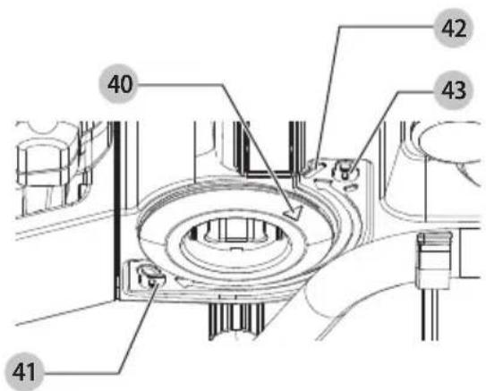
Securing the Core Drill in the Stand (Fig. A1, E–G)
WARNING: Always mount your core drill firmly to prevent movement.
- Ensure the carriage lock 2 on the left-hand side of the carriage is engaged.
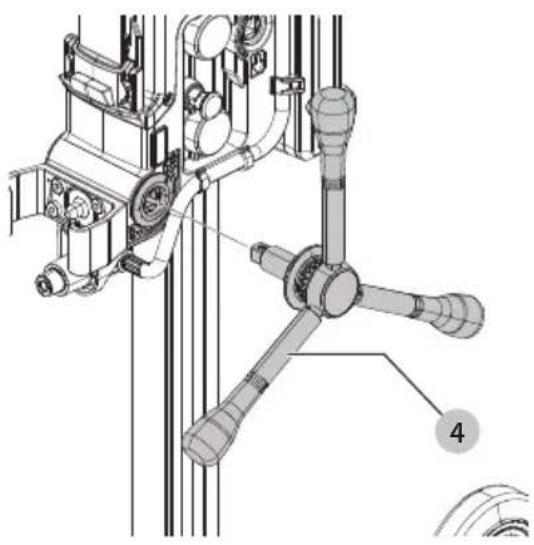
- Insert the feed handle 4 into the slot 19 on either side of the drill stand's carriage.
- Rotate the feed handle so the arrow 40 lines up with the unlocked icon 41.
- Mount the core drill to the stand by inserting it into the drill holder 5.
- To ensure proper engagement, rotate the feed handle so the arrow 40 lines up with the line 42 by the locked icon 43.
nOTE: High force is required to overcome the detent when locking the core drill into the drill stand.
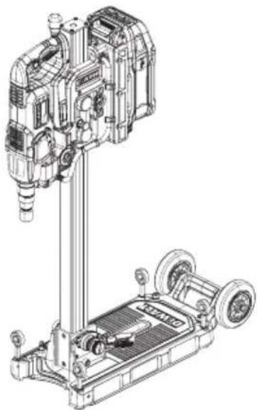
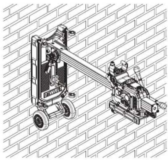
Mounting the Stand (Fig. H–L)
WARNING: Always make sure the stand is securely fastened on the surface. The stand can be mounted either vertically (Fig. H) or horizontally (Fig. I) on a surface such as a floor or a wall using an anchor or by vacuum mounting it.
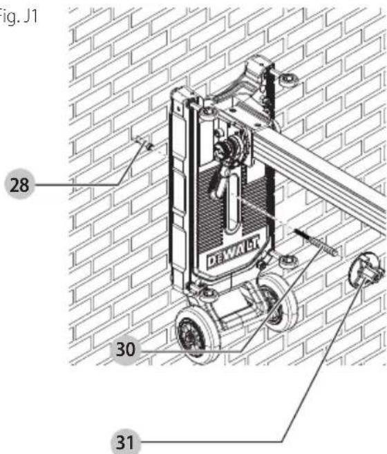
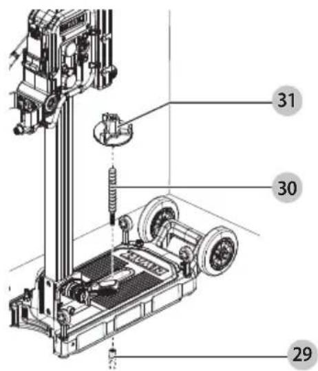
Mounting the Stand with the Recommended Fastening Set (Fig. A1, J1, J2)
A fastening set is required to secure the stand to masonry 24 (Fig. A2) or concrete 23 (Fig. A2) surfaces. We recommend using a 1/2" drop-in anchor 29, 1/2" threaded rod 30, 1/2" drop in setting tool, and clamping nut 31 to secure the base of the stand. This fastening set is included with the stand.
- Locate the stand at the desired position and mark the location of the mounting hole on the wall.
- Drill a hole at the marked location. We recommend using the DCH293R2DH cordless 1-1/8 in. L-Shape SDS PLUS rotary hammer with a DW5471 5/8" masonry drill bit.
a. In concrete and masonry: 5/8" (15.88 mm) diameter by 2" (50.8 mm) deep.
3. Insert the drop-in anchor 29 into the hole and properly install the anchor using the manufacturer's printed installation instructions (MPII).
4. Twist the threaded rod 30 into the drop-in anchor.
5. Position the stand over the anchor and threaded rod assembly. We recommend positioning the stand to line up with the 12" mark that is labeled on the base of the stand
near the anchor slot.
nOTE: Ensure the battery is not attached to stand at this time.
- Place the clamping nut 31 over the anchor and tighten down towards the base of the stand to secure.
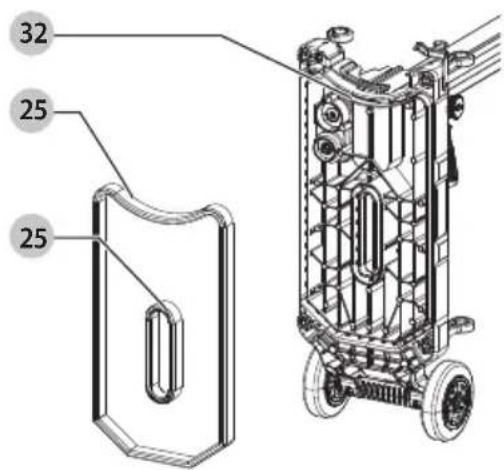
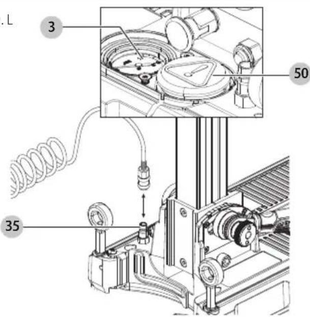
Mounting the Stand with the Vacuum Pump (Fig. K, L)
A vacuum pump can be used to secure the stand. The vacuum created in the base keeps the stand securely in position.
iIMPORTAnT: The vacuum pump must produce a vacuum of at least -0.65 bar (green zone) on the vacuum base gauge 3.
WARNING: This application works only if the stand is mounted to a flat surface (leveled concrete) which is clean and free of debris and swarf. Otherwise, the suction may drop, causing the stand to fall or move.
-
Ensure both pieces of the rubber seal are clean and have no damage.
-
Insert both pieces of the rubber seal 25 in the slots 32 on the underside of the base. Push firmly into the slots.
-
Position the stand.
iIMPORTAnT: For horizontal vacuum mounting, the stand needs to be secured with a secondary anchor set. Refer to Mounting the Stand with the Recommended Fastening Set for instructions on how to properly install the fastening set.
-
Loosen the stabilizer bolts 14 until the ends are above the bottom surface of the base.
-
Connect the hose of the vacuum pump to the connection point 34.
-
Switch on the vacuum pump. Keep the pump switched on as long as the application requires.
NOTE: The maximum core bit diameter which can be used with vacuum mounting is 6" (162 mm) wet application in concrete.
- To release the pressure, press the pressure release valve 50.
Adjusting the Stand (Fig. A1)
- Read one of the bubble levels to check whether the stand is level.
a. Bubble level 10 for vertical applications.
b. Bubble level 11 for horizontal applications.
-
If adjustment is required, proceed as follows:
-
Turn the stabilizer bolts 14 one by one until the stand is level. Adjust all bolts until each is contacting the surface to be drilled and the stand is leveled and doesn't rock.
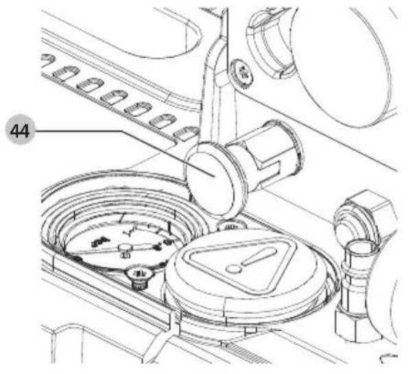
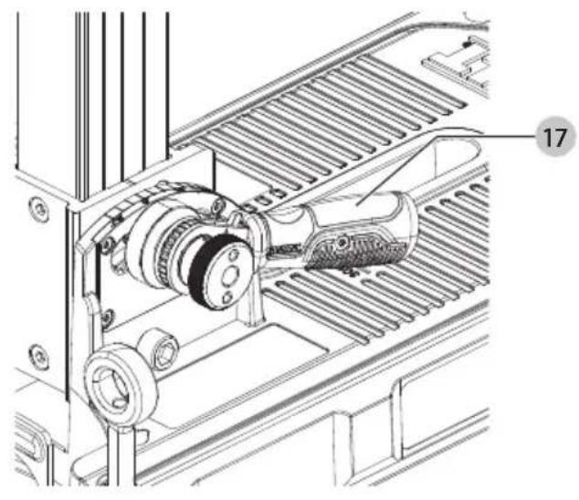
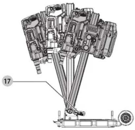
Adjusting the Drill Angle (Fig. A1, N–P)
The column can be tilted to facilitate slope drilling applications. The angle drilling scale 7 represents angles up to 45^ and can also drill inversely up to -15^ .
-
Ensure the battery has been removed and core bit is out of hole.
-
Pull the ratchet locking pin 44 out.
-
Use the ratchet handle for angular coring 17 to set the desired angle, either forwards up to -15^ or backwards up to 45^ .
-
Push the ratchet locking pin in to lock the angled position in place.
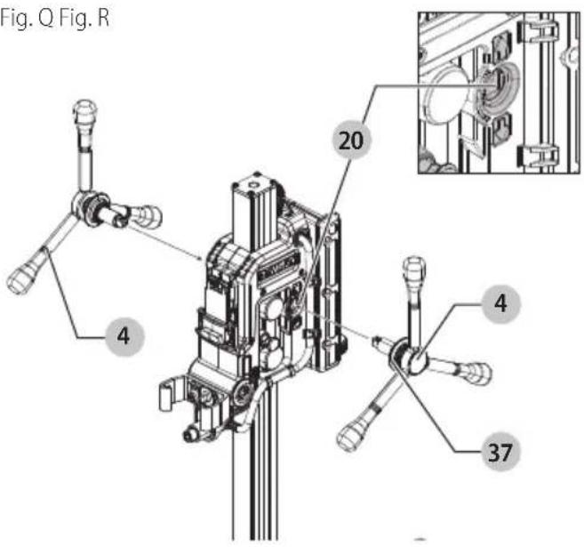
Fitting and Removing the Feed Handle (Fig. A1, Q)
The quick-release feed handle 4 can be mounted in one simple operation both to the left and the right of the stand.
-
Align the male square drive in the feed handle with the female square drive in the slot 20.
-
Push the handle onto the shaft.
To remove the feed handle from the stand, pull back on the quick release 37 and pull the feed handle out.
Adjusting the Carriage (Fig. A1, S)
After repeated use, the carriage may become loose. To adjust the play, proceed as follows:
-
Tighten the driving cap 22 as necessary.
-
Check the up and down movement of the carriage.
Adjusting the Friction (Fig. A1)
AUTION: Be careful to not decrease the friction too quickly or the carriage may fall suddenly. DO NOT adjust while drilling.
The friction knob 12 is used to increase or decrease the friction of the carriage mechanism to the mast.
-
Turn the knob clockwise to increase the friction.
-
Turn the knob counterclockwise to decrease the friction.
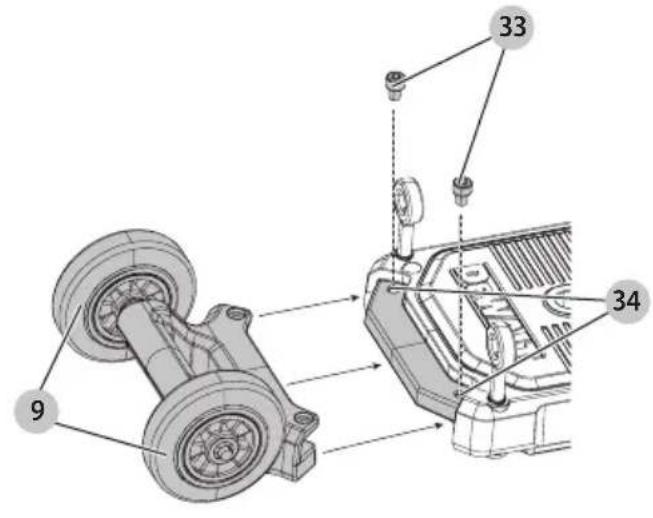
Installing and Removing the Wheel Kit (Fig. M) To Install the Wheels
-
Line the bolts 33 in the wheel kit up with the slots 34 on the base of the stand.
-
Use a #10 Allen wrench to twist the bolts of the wheel kit 9 clockwise to desired torque.
To Remove the Wheels
-
Use a #10 Allen wrench to twist the bolts of the wheel kit counterclockwise until loose.
-
Once loose, lift up and off of the base of the stand.
Prior to Operation
• Mark the spot where the hole is to be drilled.
- Mount the appropriate accessory.
• Make sure the stand is fastened securely.
- Check the friction on the carriage.
OPERATION
WARNING: To reduce the risk of serious personal injury, turn unit off and remove the battery pack before making any adjustments or removing/installing attachments or accessories. An accidental start-up can cause injury.
Installing and Removing the Battery Pack (Fig. R)
WARNING: Ensure the tool/appliance is in the off position before inserting the battery pack.
NOTE: For best results, make sure your battery pack is fully charged.
-
To install the battery pack 38 into the stand, align the battery pack with the rails and slide it in until the battery pack is firmly seated in the stand and ensure that it does not disengage.
-
To remove the battery pack from the stand, press the battery pack release button 39 and firmly pull the battery pack out of the stand. Insert it into the charger as described in the charger section of this manual.
ENGLISH
Unlocking and Locking the Carriage (Fig. A1, S)
WARNING: Always lock the carriage when the assembly is not in use.
WARNING: Make sure the feed handle is installed and is held securely.
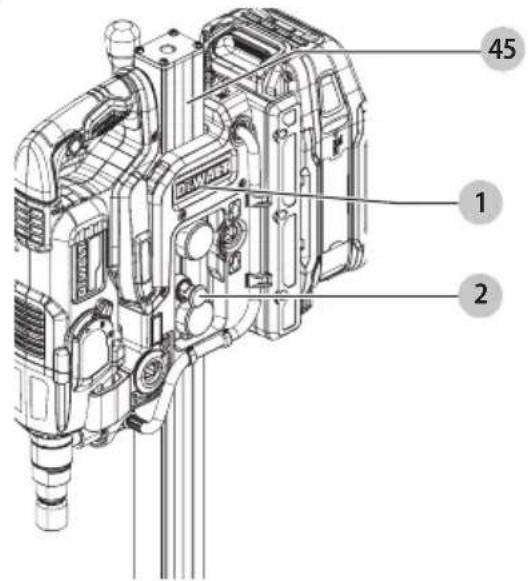
The carriage lock knob 2 allows the carriage 1 of the stand to lock into one position.
- To unlock the carriage 1 pull out the carriage lock knob.
- Rotate the feed handle 4 until the locking shaft passes the hole 45 in the column and jumps into place.
- Push the carriage lock knob in to lock the carriage in place.
General Tips for Drilling with Diamond Core Bits (Fig. A)
WARNING: Follow the core bit or manufacturer's recommendations for using the accessory.
NOTE: The use of a centering bit is not necessary while drilling with a stand.
• Take hold of the feed handle.
- Unlock the carriage.
- Switch on the drill motor in continuous mode.
- Slowly feed the accessory into the workpiece using the feed handle.
- At the start of the cut, apply light pressure to allow the accessory to perform the initial groove.
- Continue applying sufficient pressure to achieve a smooth progressive cut. Do not force. Release when heavy load indicator is activated.
• Take extra care when the accessory is about to break through the surface to prevent splintering.
• Always switch off the core drill when work is finished and before removing the battery.
• After use move the carriage upwards until the carriage locks into place. Refer to Unlocking and Locking the Carriage.
Transporting (Fig. A1)
WARNING: Always transport the stand with the carriage locked.
WARNING: Do not transport the stand with a battery installed.
The removable wheels 9 have been provided to facilitate transportation.
MAINTENANCE
WARNING: To reduce the risk of serious personal injury, turn unit off and remove the battery pack before making any adjustments or removing/installing attachments or accessories. An accidental start-up can cause injury.
Your DEWALT power tool has been designed to operate over a long period of time with a minimum of maintenance. Continuous satisfactory operation depends upon proper tool care and regular cleaning.
Cleaning (Fig. A)
WARNING: Blow dirt and dust out of all air vents with clean, dry air at least once a week. To minimize the risk of eye injury, always wear ANSI Z87.1 approved eye protection when performing this procedure.
WARNING: Never use solvents or other harsh chemicals for cleaning the non-metallic parts of the tool. These chemicals may weaken the plastic materials used in these parts. Use a cloth dampened only with water and mild soap. Never let any liquid get inside the tool; never immerse any part of the tool into a liquid.
- Clear the gear of ratchet handle 4 using a soft brush or dry cloth.
- The cover of vacuum meter 3 should be clean to see the vacuum gauge pointer.
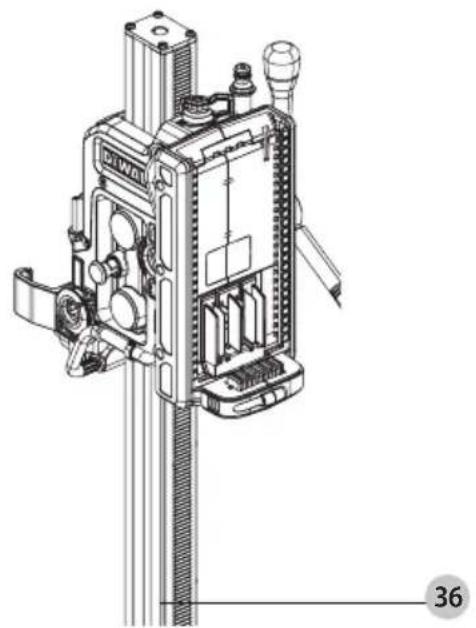
Clearing the Feed Travel (Fig. T)
The feed travel should be cleared periodically to ensure smooth operation.
- Raise the carriage 1 to the highest position possible.
- Clear the gear rack 36 using a soft brush or dry cloth.
Accessories
WARNING: Since accessories, other than those offered by DEWALT, have not been tested with this product, use of such accessories with this product could be hazardous. To reduce the risk of injury, only DEWALT-recommended accessories should be used with this product.
Recommended accessories for use with your product are available at extra cost from your local dealer or authorized service center. If you need assistance in locating any accessory, please contact DEWALT. Call 1-800-4-DEWALT (1-800-433-9258) or visit our website: www.dewalt.com.
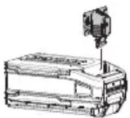
DEWALT Tool Connect™ Tag Ready (Fig. U)
Optional Accessory (Purchased separately)
WARNING: Read instruction manual for the DEWALT Tool Connect™ Tag.
WARNING: Remove battery from tool before installing the DEWALT Tool Connect™ Tag.
WARNING: When installing or replacing the DEWALT Tool Connect™ Tag, use only the screws provided. Be sure to securely tighten the screws.
Your tool comes with mounting holes 47 and fasteners 48 for installing a DEWALT Tool Connect™ Tag 49. You will need a cross head bit tip to install the tag. Screw torque should be between 0.8 and 1.2 Nm (7.1 to 10.6 in-lbs). The DEWALT Tool Connect™ Tag is designed for tracking and locating professional power tools, equipment, machines, and other assets using the DEWALT Site Manger app**. For proper installation and onboarding of the DEWALT Tool Connect™ Tag, refer to the DEWALT Tool Connect™ Tag manual.
To learn more, visit: www.DEWALT.com/en-us/jobsite-solutions/tool-connect.
**The DEWALT Site Manager app is governed by separate terms and conditions available for viewing through the mobile or web application. Additional subscription charges and third-party data charges may apply.
Repairs
The charger and batteries are not serviceable. There are no serviceable parts inside the charger or battery pack.
WARNING: To assure product SAFETY and RELIABILITY, repairs, maintenance and adjustment (including brush inspection and replacement, when applicable) should be performed by a factory service center or an authorized service center. Always use identical replacement parts.
Register Online
Thank you for your purchase. Register your product now for:
- WARRANTY SERVICE: Registering your product will help you obtain more efficient warranty service in case there is a problem with your product.
- CONFIRMATION OF OWNERSHIP: In case of an insurance loss, such as fire, flood or theft, your registration of ownership will serve as your proof of purchase.
• FOR YOUR SAFETY: Registering your product will allow us to contact you in the unlikely event a safety notification is required under the Federal Consumer Safety Act.
Register online at www.dewalt.com/account-login.
Three-Year Limited Warranty
For warranty terms, go to
www.dewalt.com/support/warranty.
To request a written copy of the warranty terms, contact: Customer Service at DEWALT Industrial Tool Co., 701 East Joppa Road, Towson, MD 21286 or call 1-800-4-DEWALT (1-800-433-9258).
LATIN AMERICA: This warranty does not apply to products sold in Latin America. For products sold in Latin America, see country-specific warranty information contained in the packaging, call the local company or see website for warranty information.
FREE WARNING LABEL REPLACEMENT: If your warning labels become illegible or are missing, call 1-800-4-DEWALT (1-800-433-9258) for a free replacement.
Technical Data
| Voltage V 60* |
| Max. water pressure bar 3 |
| Vacuum pump PSI -10.8 |
| Weight lbs (kg) 40.0 (18.2) |
Troubleshooting
If your drill stand seems not to operate properly, follow the instructions below. If this does not solve the problem, please contact your repair agent.
| Problem Solution | |
| Loose carriage | 1. Use a #8 Allen wrench to tighten the carriage to the mast in the slot on the right-hand side. |
| Core bit stuck when using the stand 1. Remove the battery from the core drill.2. Release the core drill from the stand by opening the locking mechanism.3. Disengage the core drill from the stand by moving the elevation portion down.4. Remove the stand from the area.5. Use wrenches to release the spindle from the core bit.6. Turn the spindle as long as it is disconnected from the core bit.7. Place the core drill and the battery in a secure dry place.8. Remove the core bit from hole. | |
| Vacuum function doesn’t work | 1. Loosen the stabilizer bolts until the ends are above the bottom surface of the base.2. Stand on the base or apply a pressure to the base. |
FRAnÇAis


Eje Central Lázaro Cárdenas No. 18 - Local (55) 5588 9377 D, Col. Obrera
MERIDA, YUC
Calle 63 #459-A - Col. Centro (999) 928 5038
MONTERREY, N.L.
Av. Francisco I. Madero 831 Poniente - Col. (818) 375 23 13 Centro
PUEBLA, PUE
17 Norte #205 - Col. Centro (222) 246 3714
QUERETARO, QRO
Av. San Roque 274 - Col. San Gregorio (442) 2 17 63 14
SAN LUIS POTOSI, SLP
Col. Santa Fe Alvaro Obregon,
Ciudad de Mexico, Mexico.
C.P 01210
TEL(52) 55 53267100
R.F.C.BDE8106261W7
Registro en Línea
The DCPS151 POWERSHIFT® 6.375IN core drill stand is compatible with the mentioned FLEXVOLT® batteries when those batteries are put into the DCAFVPS FLEXVOLT® Adaptor.
WARNING: Use of any other battery packs may create a risk of injury and fire.
NOTE: DO NOT charge when the battery pack is below 40 °F ( 4.5 °C ) or above 104 °F ( 40 °C ). Do not store or use the tool and battery pack in locations where the temperature may reach or exceed 104 °F ( 40 °C ).