
DCF870 - Drill DEWALT - Free user manual and instructions
Find the device manual for free DCF870 DEWALT in PDF.

| Product type | Cordless hydraulic impact wrench |
| Brand | DeWalt |
| Model | DCF870 |
| Rated voltage | 18 V |
| Battery type | Li-Ion (compatible with DeWalt XR batteries) |
| No-load speed (Mode 1) | 0-1100 rpm |
| No-load speed (Mode 2) | 0-3000 rpm |
| No-load speed (Mode 3) | 0-3000 rpm (with 20 min work light) |
| Maximum torque | 56 Nm |
| Tool holder | 1/4" (6.35 mm) hex quick-release chuck |
| Weight (without battery pack) | 1.0 kg |
| Sound pressure level (LPA) | 93 dB(A) |
| Sound power level (LWA) | 101 dB(A) |
| Vibration value (ah) | 19.5 m/s² |
| Work light | 3 LEDs with 20 s delay and 20 min mode |
| Speed selector | 3 modes (slow, fast, fast + light) |
| Rotation direction | Forward, reverse, center lock |
| Main functions | Impact driving, screwdriving in wood and metal, work light |
| Maintenance and cleaning | Clean with a damp cloth and mild soap, do not immerse |
| Safety | Motor brake, switch lock, overload protection |
| Spare parts and repairability | Replacement parts available from DeWalt customer service |
| General information | Professional tool, Tool Connect ready, belt hook included |
Frequently Asked Questions - DCF870 DEWALT
User questions about DCF870 DEWALT
0 question about this device. Answer the ones you know or ask your own.
Ask a new question about this device
Download the instructions for your Drill in PDF format for free! Find your manual DCF870 - DEWALT and take your electronic device back in hand. On this page are published all the documents necessary for the use of your device. DCF870 by DEWALT.
USER MANUAL DCF870 DEWALT
English (original instructions) 17
natural_image
Icon of a person using a computer (no text or symbols)Fig. A
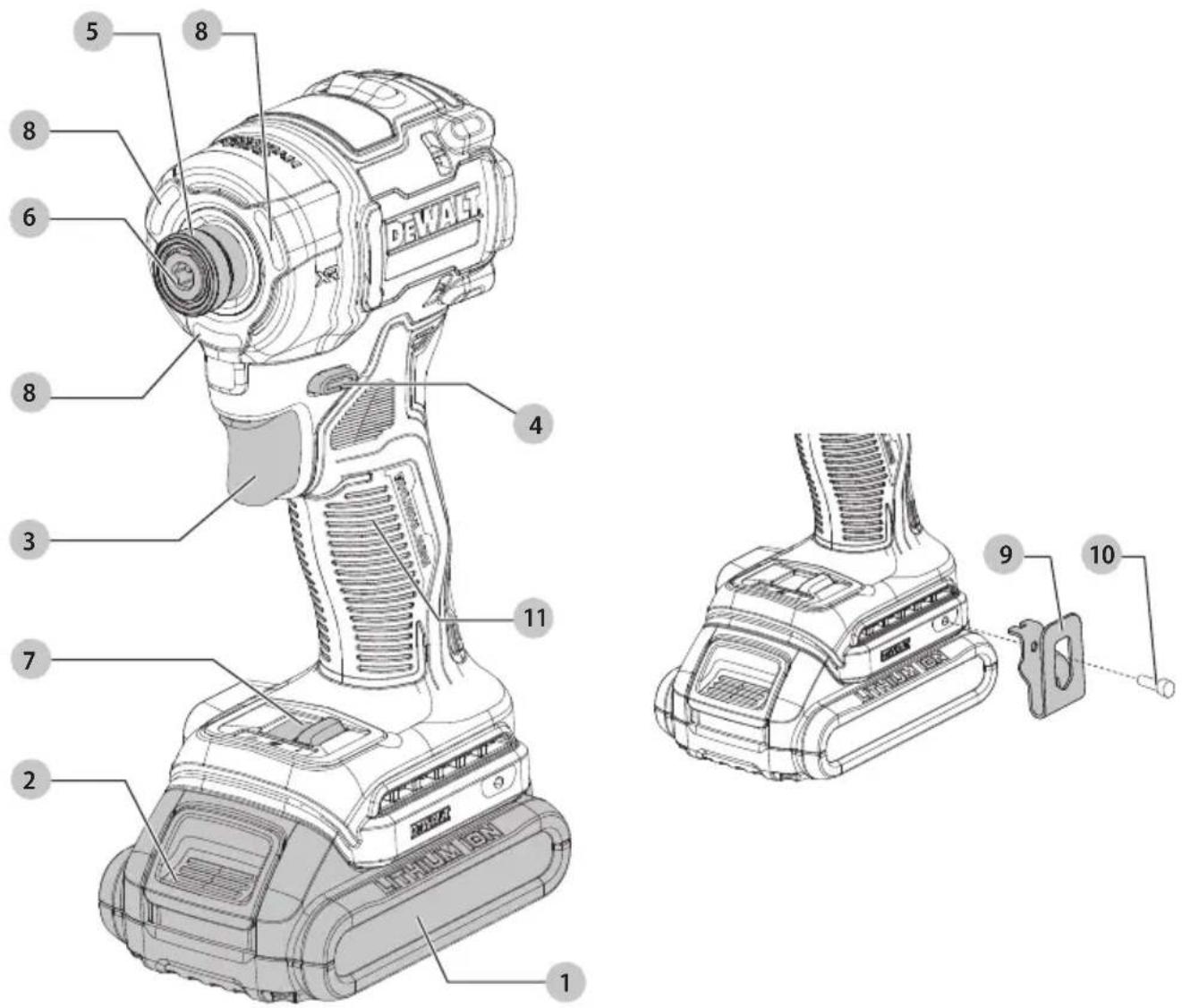
Fig. B
18V XR HYDRAULISK SLAGSKRUEMASKINE
DCF870

Installation of Tool Connect™ Chip
Vice-President Engineering, PTE-Europe
18V XR HYDRAULIC IMPACT DRIVER
DCF870

WARNING: Read all safety warnings, instructions, illustrations, and specifications in this manual,

including the battery and charger sections provided in an original tool manual or the separate Batteries and Chargers manual. Manuals can be obtained by contacting
Customer Service (refer to the back page of this manual).
Technical Data
| DCF870 | ||
| Voltage V | DC | 18 |
| Type 1 | ||
| Battery type Li-Ion | ||
| Power output W 500 | ||
| No load speed | ||
| Mode 1 rpm 0-1100 | ||
| Mode 2 rpm 0-3000 | ||
| Mode 3 w/20 minute worklight rpm 0-3000 | ||
| Max torque Nm 56 | ||
| Tool holder mm 6.35 | ||
| Weight (without battery pack) kg | 1.0 | |
| Noise values and vibration values (triax vector sum) according to EN62841-2-2: | ||
| L_PA (emission sound pressure level) | dB(A) 93 | |
| L_WA (sound power level) | dB(A) | 101 |
| K (uncertainty for the given sound level) | dB(A) | 3 |
| Vibration emission value a_h = | m/s2 | 19.5 |
| Uncertainty K = | m/s2 | 2.6 |
The vibration and/or noise emission level given in this information sheet has been measured in accordance with a standardised test given in EN62841-2-2 and may be used to compare one tool with another. It may be used for a preliminary assessment of exposure.
▲ WARNING: The declared vibration and/or noise emission level represents the main applications of the tool. However, if the tool is used for different applications, with different accessories or is poorly maintained, the vibration and/or noise emission may differ. This may significantly increase the exposure level over the total working period. An estimation of the level of exposure to vibration and/or noise should also take into account the times when the tool is switched off or when it is running but not actually doing the job. This may significantly reduce the exposure level over the total working period.
Identify additional safety measures to protect the operator from the effects of vibration and/or noise such as: maintain the tool and the accessories, keep the hands warm (relevant for vibration), organisation of work patterns.
EC-Declaration of Conformity
Machinery Directive

Cordless Hydraulic Impact Driver
DCF870
DEWALT declares that these products described under Technical Data are in compliance with:
2006/42/EC, EN62841-1:2015+A11:2022; EN62841-2-2:2014+AC:2015.
These products also comply with Directive 2014/30/EU and 2011/65/EU. For more information, please contact DEWALT at the following address or refer to the back of the manual.
The undersigned is responsible for compilation of the technical file and makes this declaration on behalf of DEWALT.

Markus Rompel
Vice-President Engineering, PTE-Europe
65510, Idstein, Germany
05.03.2024
DECLARATION OF CONFORMITY THE SUPPLY OF MACHINERY (SAFETY) REGULATIONS

Cordless Hydraulic Impact Driver
DCF870
DEWALT declares that these products described under
Technical Data are in compliance with:
The Supply of Machinery (Safety) Regulations, 2008, S.I. 2008/1597 (as amended),
EN62841-1:2015+A11:2022; EN62841-2-2:2014+AC:2015.
These products conform to the following UK Regulations:
Electromagnetic Compatibility Regulations, 2016, S.I.2016/1091 (as amended).
The Restriction of the Use of Certain Hazardous Substances in Electrical and Electronic Equipment Regulations 2012, S.I. 2012/3032 (as amended).
For more information, please contact DEWALT at the following address or refer to the back of the manual.
The undersigned is responsible for compilation of the technical file and makes this declaration on behalf of DEWALT.

Karl Evans
Vice President Professional Power Tools EANZ GTS
DEWALT UK,
Meadowfield Avenue,
Spennymoor, DL16 6YJ,
England
05.03.2024

WARNING: To reduce the risk of injury, read the instruction manual.
Definitions: Safety Guidelines
The definitions below describe the level of severity for each signal word. Please read the manual and pay attention to these symbols.
▲ANGER: Indicates an imminently hazardous situation which, if not avoided, will result in death or serious injury.
WARNING: Indicates a potentially hazardous situation which, if not avoided, could result in death or serious injury.
CAUTION: Indicates a potentially hazardous situation which, if not avoided, may result in minor or moderate injury.
NOTICE: Indicates a practice not related to personal injury which, if not avoided, may result in property damage.
▲ denotes risk of electric shock.
Denotes risk of fire.
GENERAL POWER TOOL SAFETY WARNINGS
WARNING: Read all safety warnings, instructions, illustrations and specifications provided with this power tool. Failure to follow all instructions listed below may result in electric shock, fire and/or serious injury.
SAVE ALL WARNINGS AND INSTRUCTIONS FOR FUTURE REFERENCE
The term "power tool" in the warnings refers to your mains-operated (corded) power tool or battery-operated (cordless) power tool.
1) Work Area Safety
a) Keep work area clean and well lit. Cluttered or dark areas invite accidents.
b) Do not operate power tools in explosive atmospheres, such as in the presence of flammable liquids, gases or dust.
Power tools create sparks which may ignite the dust or fumes.
c) Keep children and bystanders away while operating a power tool. Distractions can cause you to lose control.
2) Electrical Safety
a) Power tool plugs must match the outlet. Never modify the plug in any way. Do not use any adapter plugs with earthed (grounded) power tools. Unmodified plugs and matching outlets will reduce risk of electric shock.
b) Avoid body contact with earthed or grounded surfaces, such as pipes, radiators, ranges and refrigerators. There is an increased risk of electric shock if your body is earthed or grounded.
c) Do not expose power tools to rain or wet conditions.
Water entering a power tool will increase the risk of electric shock.
d) Do not abuse the cord. Never use the cord for carrying, pulling or unplugging the power tool. Keep cord away from heat, oil, sharp edges or moving parts. Damaged or entangled cords increase the risk of electric shock.
e) When operating a power tool outdoors, use an extension cord suitable for outdoor use. Use of a cord suitable for outdoor use reduces the risk of electric shock.
f) If operating a power tool in a damp location is unavoidable, use a residual current device (RCD) protected supply. Use of an RCD reduces the risk of electric shock.
3) Personal Safety
a) Stay alert, watch what you are doing and use common sense when operating a power tool. Do not use a power tool while you are tired or under the influence of drugs, alcohol or medication. A moment of inattention while operating power tools may result in serious personal injury.
b) Use personal protective equipment. Always wear eye protection. Protective equipment such as a dust mask, non-skid safety shoes, hard hat or hearing protection used for appropriate conditions will reduce personal injuries.
c) Prevent unintentional starting. Ensure the switch is in the off position before connecting to power source and/or battery pack, picking up or carrying the tool. Carrying power tools with your finger on the switch or energising power tools that have the switch on invites accidents.
d) Remove any adjusting key or wrench before turning the power tool on. A wrench or a key left attached to a rotating part of the power tool may result in personal injury.
e) Do not overreach. Keep proper footing and balance at all times. This enables better control of the power tool in unexpected situations.
f) Dress properly. Do not wear loose clothing or jewellery. Keep your hair and clothing away from moving parts. Loose clothes, jewellery or long hair can be caught in moving parts.
g) If devices are provided for the connection of dust extraction and collection facilities, ensure these are connected and properly used. Use of dust collection can reduce dust-related hazards.
h) Do not let familiarity gained from frequent use of tools allow you to become complacent and ignore tool safety principles. A careless action can cause severe injury within a fraction of a second.
4) Power Tool Use and Care
a) Do not force the power tool. Use the correct power tool for your application. The correct power tool will do the job better and safer at the rate for which it was designed.
b) Do not use the power tool if the switch does not turn it on and off. Any power tool that cannot be controlled with the switch is dangerous and must be repaired.
c) Disconnect the plug from the power source and/or remove the battery pack, if detachable, from the power tool before making any adjustments, changing accessories, or storing power tools. Such preventive safety measures reduce the risk of starting the power tool accidentally.
d) Store idle power tools out of the reach of children and do not allow persons unfamiliar with the power tool or these instructions to operate the power tool. Power tools are dangerous in the hands of untrained users.
e) Maintain power tools and accessories. Check for misalignment or binding of moving parts, breakage of parts and any other condition that may affect the power tool's operation. If damaged, have the power tool repaired before use. Many accidents are caused by poorly maintained power tools.
f) Keep cutting tools sharp and clean. Properly maintained cutting tools with sharp cutting edges are less likely to bind and are easier to control.
g) Use the power tool, accessories and tool bits, etc. in accordance with these instructions, taking into account the working conditions and the work to be performed. Use of the power tool for operations different from those intended could result in a hazardous situation.
h) Keep handles and grasping surfaces dry, clean and free from oil and grease. Slippery handles and grasping surfaces do not allow for safe handling and control of the tool in unexpected situations.
5) Battery Tool Use and Care
a) Recharge only with the charger specified by the manufacturer. A charger that is suitable for one type of battery pack may create a risk of fire when used with another battery pack.
b) Use power tools only with specifically designated battery packs. Use of any other battery packs may create a risk of injury and fire.
c) When battery pack is not in use, keep it away from other metal objects, like paper clips, coins, keys, nails, screws or other small metal objects, that can make a connection from one terminal to another. Shorting the battery terminals together may cause burns or a fire.
d) Under abusive conditions, liquid may be ejected from the battery; avoid contact. If contact accidentally occurs, flush with water. If liquid contacts eyes, additionally seek medical help. Liquid ejected from the battery may cause irritation or burns.
e) Do not use a battery pack or tool that is damaged or modified. Damaged or modified batteries may exhibit unpredictable behaviour resulting in fire, explosion or risk of injury.
f) Do not expose a battery pack or tool to fire or excessive temperature. Exposure to fire or temperature above 130 °C may cause explosion.
g) Follow all charging instructions and do not charge the battery pack or tool outside the temperature range specified in the instructions. Charging improperly or at temperatures outside the specified range may damage the battery and increase the risk of fire.
6) Service
a) Have your power tool serviced by a qualified repair person using only identical replacement parts. This will ensure that the safety of the power tool is maintained.
b) Never service damaged battery packs. Service of battery packs should only be performed by the manufacturer or authorised service providers.
Impact Wrench/Driver Safety Warnings-All Operations
- Hold the power tool by insulated gripping surfaces when performing an operation where the fastener may contact hidden wiring. Fasteners contacting a "live" wire may make exposed metal parts of the power tool "live" and could give the operator an electric shock.
- Wear ear protectors during use. Exposure to noise can cause hearing loss.
WARNING: Impact wrenches are not torque wrenches. DO NOT use this tool for tightening fasteners to specified torques. An independent, calibrated torque measurement device such as a torque wrench should be used when under-tightened or overtightened fasteners can lead to the failure of the joint.
- Use clamps or another practical way to secure and support the workpiece to a stable platform. Holding the work by hand or against your body leaves it unstable and may lead to loss of control.
- Wear safety goggles or other eye protection. Hammering and drilling operations cause chips to fly. Flying particles can cause permanent eye damage.
- Do not operate this tool for long periods of time. Vibration caused by tool action may be harmful to your hands and arms. Use gloves to provide extra cushion and limit exposure by taking frequent rest periods.
- Accessories and tools get hot during operation. Wear gloves when touching them.
Residual Risks
In spite of the application of the relevant safety regulations and the implementation of safety devices, certain residual risks cannot be avoided. These are:
- Impairment of hearing.
- Risk of personal injury due to flying particles.
- Risk of burns due to accessories becoming hot during operation.
- Risk of personal injury due to prolonged use.
SAVE THESE INSTRUCTIONS
Battery Type
These battery packs may be used:
| Battery (kg) Battery (kg) | |||
| DCB546 | 1.08 | DCB184/B/G | 0.62 |
| DCB547/G | 1.46 DCB185 | 0.35 | |
| DCB548 | 1.46 DCB187 | 0.54 | |
| DCB549 | 2.12 DCB189 | 0.54 | |
| DCB181 | 0.35 | DCBP034/G | 0.32 |
| DCB182 | 0.61 | DCBP518/G | 0.75 |
| DCB183/B/G | 0.40 | ||
Refer to the battery/charger manual for more information.
Package Contents
The package contains:
1Impactdriver
1 Charger (not included with N and NT versions)
1 Magnetic bit holder
1Belthook
1 Kitbox (included with T versions)
1ToolConnect ™ App instruction manual (B models)
1 Li-lon battery pack (C1, D1, E1, G1, H1, L1, M1, P1, Q1, S1, T1, U1, X1, Y1, Z1 models)
2 Li-Ion battery packs (C2, D2, E2, G2, H2, L2, M2, P2, Q2, S2, T2, U2, X2, Y2, Z2 models)
3 Li-lon battery packs (C3, D3, E3, G3, H3, L3, M3, P3, Q3, S3, T3, U3, X3, Y3, Z3 models)
1 Instructionmanual
nOTE: Battery packs, chargers and kitboxes are not included with N models. Battery packs and chargers are not included with NT models. B models include Bluetooth® battery packs.
NOTE: The Bluetooth® word mark and logos are registered trademarks owned by the Bluetooth®, SIG, Inc. and any use of
such marks by DEWALT is under license. Other trademarks and trade names are those of their respective owners.
- Check for damage to the tool, parts or accessories which may have occurred during transport.
• Take the time to thoroughly read and understand this manual prior to operation.
Markings on Tool
The following pictograms are shown on the tool:

Read instruction manual before use.

Visible radiation. Do not stare into light.
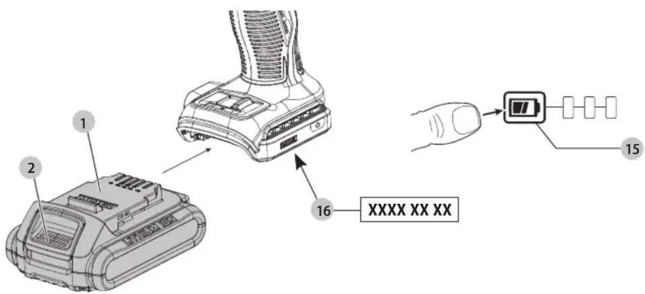
Date Code Position (Fig. B)
The production date code 16 consists of a 4-digit year followed by a 2-digit week and is extended by a 2-digit factory code.
Description (Fig. A)
WARNING: Never modify the power tool or any part of it.
Damage or personal injury could result.
1 Battery pack
2 Battery pack release button
3 Variable speed trigger
4 Forward/reverse control button
5 Chuck collar
6 1/4" (6.35 mm) hex quick-release chuck
7 Speed selector
8 Worklight
9 Belt hook
10 Mounting screw
11 Main handle
Intended Use
This impact driver is designed for professional impact screwdriving applications. The impact function makes this tool particularly useful for driving fasteners in wood, and metal.
DO NOT use under wet conditions or in the presence of flammable liquids or gases.
This impact driver is a professional power tool.
DO NOT let children come into contact with the tool. Supervision is required when inexperienced operators use this tool.
- Young children and the infirm. This appliance is not intended for use by young children or infirm persons without supervision.
- This product is not intended for use by persons (including children) suffering from diminished physical, sensory or mental abilities; lack of experience, knowledge or skills unless they are supervised by a person responsible for their safety. Children should never be left alone with this product.
ASSEMBLY AND ADJUSTMENTS
WARNING: To reduce the risk of serious personal injury, turn tool off and disconnect battery pack before making any adjustments or removing/installing attachments or accessories. An accidental start-up can cause injury.
WARNING: Use only DEWALT batteries and chargers.
Inserting and Removing the Battery Pack from the Tool (Fig. B)
NOTE: Make sure your battery pack 1 is fully charged.
To Install the Battery Pack into the Tool Handle
- Align the battery pack with the rails inside the tool's handle (Fig. B).
- Slide it into the handle until the battery pack is firmly seated in the tool and ensure that you hear the lock snap into place.
To Remove the Battery Pack from the Tool
- Press the battery release button 2 and firmly pull the battery pack out of the tool handle.
- Insert battery pack into the charger.
Fuel Gauge Battery Packs (Fig. B)
Some DEWALT battery packs include a fuel gauge, which consists of three green LED lights that indicate the level of charge remaining in the battery pack.
To actuate the fuel gauge, press and hold the fuel gauge button 15. A combination of the three green LED lights will illuminate, designating the level of charge left. When the level of charge in the battery is below the usable limit, the fuel gauge will not illuminate and the battery will need to be recharged.
NOTE: The fuel gauge is only an indication of the charge left on the battery pack. It does not indicate tool functionality and is subject to variation based on product components, temperature and end-user application.
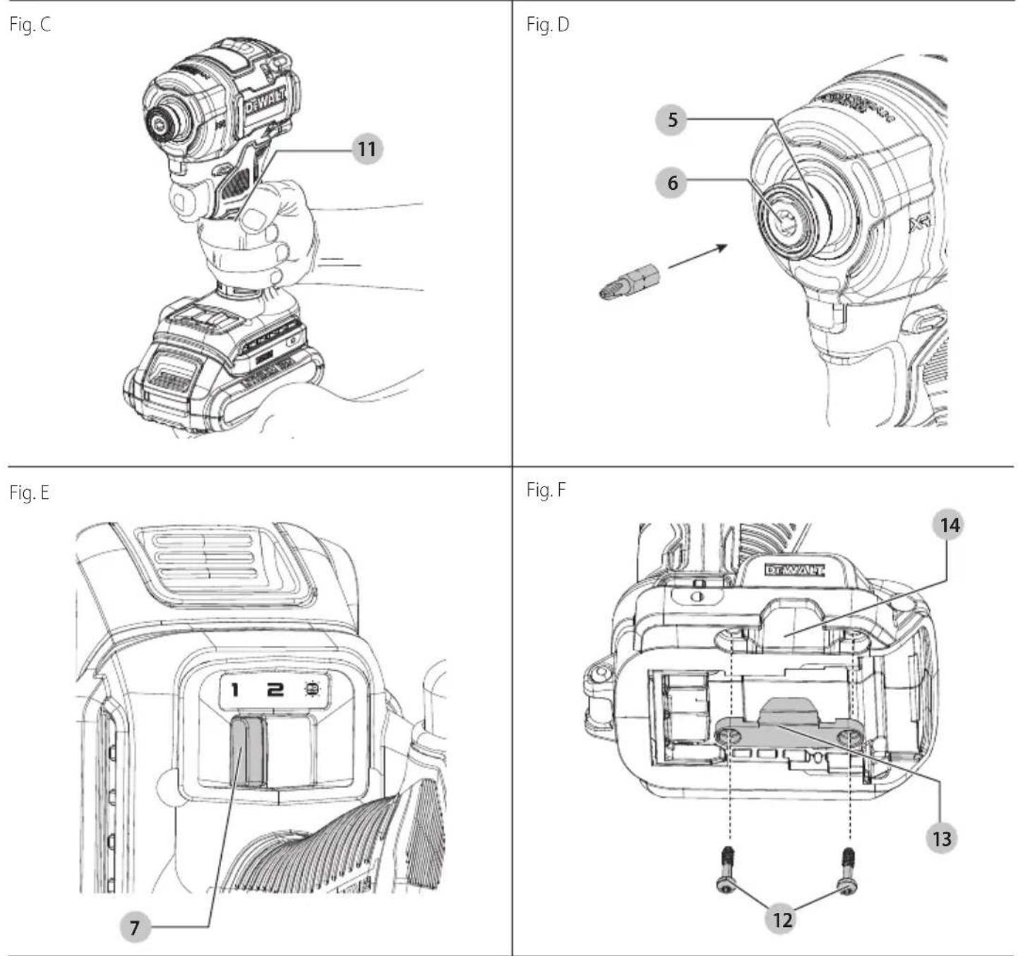
Quick-Release Chuck (Fig. A, D)
WARNING: Use only impact accessories. Non-impact accessories may break and cause a hazardous condition. Inspect accessory prior to use to ensure that it contains no cracks.
NOTE: The quick-release chuck 6 accepts 1/4" hex accessories. Place the forward/reverse control button 4 in the lock-off (center) position and remove battery pack 1 before changing accessories.
To install an accessory, fully insert the accessory. The accessory is locked into place (Fig. D).
To remove an accessory, pull the chuck collar 5 away from the front of the tool. Remove the accessory (Fig. D).
OPERATION
Instructions for Use
WARNING: Always observe the safety instructions and applicable regulations.
WARNING: To reduce the risk of serious personal injury, turn tool off and disconnect battery pack before making any adjustments or removing/installing attachments or accessories. An accidental start-up can cause injury.
Proper Hand Position (Fig. C)
WARNING: To reduce the risk of serious personal injury, ALWAYS use proper hand position as shown.
WARNING: To reduce the risk of serious personal injury, ALWAYS hold securely in anticipation of a sudden reaction. Proper hand position requires one hand on the main handle 11.
Variable Speed Trigger and Forward/Reverse Control Button (Fig. A)
The tool is turned on and off by pulling and releasing the variable speed trigger 3. The farther the variable speed trigger is depressed,
the higher the speed of the tool. Your tool is equipped with a brake. The chuck will stop as soon as the variable trigger is fully released.
A forward/reverse control button 4 determines the rotational direction of the tool and also serves as a lock-off button.
- To select forward rotation (clockwise), release the variable speed trigger and depress the forward/reverse control button on the right side of the tool.
- To select reverse (counterclockwise), depress the forward/ reverse control button on the left side of the tool.
NOTE: The center position of the forward/reverse control button locks the tool in the off position. When changing the position of the control button, be sure the trigger is released.
NOTE: Continuous use in variable speed range is not recommended. It may damage the switch and should be avoided.
NOTE: The first time the tool is run after changing the direction of rotation, you may hear a click on start-up. This is normal and does not indicate a problem.
Speed Selector (Fig. A, E)
NOTE: Do not change speeds when the tool is running. Always allow the tool to come to a complete stop before changing speed. Your tool is equipped with a speed selector 7 which allows you to select one of two speeds for greater versatility. Select the speed based on the maximum speed/torque needed and control the speed of the tool using the variable speed trigger 3.
Specifications
| Mode Application RPM | |
| Mode 1 Low speed 0-1100 forward | 0-1100 reverse |
| Mode 2 High speed 0-3000 forward | 0-3000 reverse |
| Mode 3 (20 Minute Worklight mode) Refer to Worklights section. | High speed 0-3000 forward0-3000 reverse |
- To select Mode 1 (low speed setting), turn the tool off and permit it to stop. Slide the speed selector 7 to the far left (with front of tool facing away).
- To select Mode 2 (high speed setting), turn the tool off and permit it to stop. Slide the speed selector 7 to the center position.
- To select Mode 3 (20 minute worklight mode) (high speed setting), turn the tool off and permit it to stop. Slide the speed selector 7 to the far right (with front of tool facing away).
NOTE: Mode 3 (20 minute worklight mode) provides the same application and RPM speed as Mode 2.
If the tool does not change speeds, confirm that the speed selection switch is completely engaged in the forward or back position.
Worklights (Fig. A)
AUTION: Do not stare into worklight. Serious eye injury could result.
There are three worklights 8 located around the chuck collar 5. The worklights are activated when the variable speed trigger 3 is depressed. In low speed mode when the variable speed trigger is released, the worklight will stay illuminated for up to 20 seconds. If the variable speed trigger switch remains depressed, the worklights will remain on.
20 Minute Worklight Mode
Mode 3 will activate the tool's worklights. The worklights will run for 20 minutes after the variable speed trigger is released.
WARNING: While using the tool in worklight mode, do not stare at the lights or place the drill in a position which may cause anyone to stare into the worklights. Serious eye injury could result.
AUTION: When using the tool with the worklights, be sure it is secured on a stable surface where it will not cause a tripping or falling hazard.
AUTION: Remove all accessories from the chuck before using the drill in worklight mode. Personal injury or property damage could result.
Usage (Fig. A)
SAUTION: Ensure fastener and/or system will withstand the level of torque generated by the tool. Excessive torque may cause breakage and possible personal injury.
- Place the accessory on the fastener head. Keep the tool pointed straight at the fastener.
- Press variable speed trigger 3 to start operation. Release variable speed trigger to stop operation.
Always check torque with a torque wrench, as the fastening torque is affected by many factors including the following:
- Voltage: Low voltage, due to a nearly discharged battery, will reduce fastening torque.
- Accessory size: Failure to use the correct accessory size will cause a reduction in fastening torque.
- Bolt size: Larger bolt diameters generally require higher fastening torque. Fastening torque will also vary according to length, grade, and torque coefficient.
- Bolt: Ensure that all threads are free of rust and other debris to allow proper fastening torque.
- Material: The type of material and surface finish of the material will affect fastening torque.
- Fastening time: Longer fastening time results in increased fastening torque. Using a longer fastening time than recommended could cause the fasteners to be overstressed, stripped or damaged.
Tool Connect™ Chip (Fig. A, F)
WARNING: To reduce the risk of injury, remove battery pack 1 before any Tool Connect™ interaction. Your tool is Tool Connect™ Chip ready and has a location for installation of a Tool Connect™ Chip.
Tool Connect™ Chip is an optional application for your smart device (such as a smart phone or tablet) that connects the device to utilize the mobile application for inventory management functions.
Refer to Tool Connect™ Chip Instruction Sheet for more information.
Installing the Tool Connect™ Chip
- Remove the retaining screws 12 that hold the Tool Connect™ Chip protective cover 13 into the tool.
- Remove the protective cover and insert the Tool Connect™ Chip into the empty pocket 14.
- Ensure that the Tool Connect™ Chip is flush with the housing. Secure it with the retaining screws and tighten the screws.
- Refer to Tool Connect™ Chip Instruction Sheet for further instructions.
MAINTENANCE
Your power tool has been designed to operate over a long period of time with a minimum of maintenance. Continuous satisfactory operation depends upon proper tool care and regular cleaning.
WARNING: To reduce the risk of serious personal injury, turn tool off and disconnect battery pack before making any adjustments or removing/installing attachments or accessories. An accidental start-up can cause injury. The charger and battery pack are not serviceable.
Lubrication
Your power tool requires no additional lubrication.
Cleaning
WARNING: Electrical shock and mechanical hazard. Disconnect the electrical appliance from the power source before cleaning.
WARNING: To ensure safe and efficient operation, always keep the electrical appliance and the ventilation slots clean.
WARNING: Never use solvents or other harsh chemicals for cleaning the non-metallic parts of the tool. These chemicals may weaken the materials used in these parts. Use a cloth dampened only with water and mild soap. Never let any liquid get inside the tool; never immerse any part of the tool into a liquid. Ventilation slots can be cleaned using a dry, soft non-metallic brush and/or a suitable vacuum cleaner. Do not use water or any cleaning solutions. Wear approved eye protection and an approved dust mask.
Optional Accessories
WARNING: Since accessories, other than those offered by DEWALT, have not been tested with this product, use of such accessories with this tool could be hazardous. To reduce the risk of injury, only DEWALT recommended accessories should be used with this product. Consult your dealer for further information on the appropriate accessories.
Impact Accessories
WARNING: Use only impact accessories. Non-impact accessories may break and cause a hazardous condition. Inspect accessories prior to use to ensure that they contain no cracks.
Belt Hook (Fig. A)
WARNING: Drop Hazard. To reduce the risk of serious personal injury, DO NOT use the belt hook for tethering or securing the tool to a person or object during use when elevated.
WARNING: To reduce the risk of serious personal injury, DO NOT suspend tool overhead or suspend objects from the belt hook. ONLY hang tool's belt hook from a work belt.
WARNING: To reduce the risk of serious personal injury, ensure the screw holding the belt hook is secure. NOTE: Bit clip and belt hook cannot be used with the lanyard-ready attachment kit installed.
IMPORTANT: When attaching or replacing the belt hook, use only the screw 10 that is provided. Be sure to securely tighten the screw. The belt hook 9 can be attached to either side of the tool using only the screw 10 provided, to accommodate left- or right-handed users. If the hook is not desired at all, it can be removed from the tool.
To move belt hook, remove the screw that holds the belt hook in place then reassemble on the opposite side. Be sure to securely tighten the screw.
Protecting the Environment

Separate collection. Products and batteries marked with this symbol must not be disposed of with normal household waste.

Products and batteries contain materials that can be covered or recycled, reducing the demand for raw materials. Please recycle electrical products and batteries using to local provisions. Further information is available at helpU.com.
Rechargeable Battery Pack
This long-life battery pack must be recharged when it fails to produce sufficient power on jobs that were easily done before. At the end of its technical life, discard it with due care for our environment:
- Run the battery pack down completely, then remove it from the tool.
- Li-Ion cells are recyclable. Take them to your dealer or a local recycling station. The collected battery packs will be recycled or disposed of properly.
DESTORNILLADOR DE IMPACTO HIDRÁULICO 18V XR DCF870

Bloc-batterie rechargeable
Vice-President Engineering, PTE-Europe
WAARSCHUWING: Lees alle
BEWAAR ALLE WAARSCHUWINGEN EN INSTRUCTIES ALS TOEKOMSTIG REFERENTIEMATERIAA
2 Li-ionaccu's (modellen C2, D2, E2, G2, H2, L2, M2, P2, Q2, S2, T2, U2, X2, Y2, Z2)
3 Li-ionaccu's (modellen C3, D3, E3, G3, H3, L3, M3, P3, Q3, S3, T3, U3, X3, Y3, Z3)
1Gebruiksaanwijzing
Vice-President Engineering, PTE-Europe
18V XR HYDRAULINEN ISKUVÄÄNNIN
DCF870

Vice-President Engineering, PTE-Europe
DEWALT, Richard-Klinger-Straße 11, 65510, Idstein, Tyskland
05.03.2024
