CGW LUX 90 5G AI AL DR CI - Cooker TEKA - Free user manual and instructions
Find the device manual for free CGW LUX 90 5G AI AL DR CI TEKA in PDF.

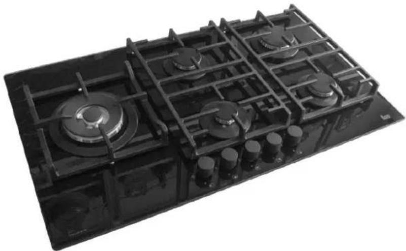
| Product type | Built-in gas hob (5 burners) |
| Brand | Teka |
| Model | CGW LUX 90 5G AI AL DR CI |
| Cut-out dimensions (W x D) | 833 x 475 mm |
| Electrical supply | 220-240 V ~ 50/60 Hz |
| Compatible gases | G20 (natural gas), G30 (butane), G31 (propane) |
| Supply pressure | 20 mbar (G20), 28-30 mbar (G30), 37 mbar (G31) |
| Burners | 1 ultra-rapid (5 kW), 2 rapid (2.8 kW), 1 semi-rapid (1.75 kW), 1 semi-rapid reduced (1.4 kW), 1 auxiliary (1 kW) |
| Ignition | Automatic electric (with safety thermocouple) |
| Surface type | Tempered glass |
| Sealing gasket | Included for recessed installation (adhesive) |
| Safety functions | Thermocouples on all burners, automatic shut-off in case of flame failure |
| Gas convertibility | Yes (nozzles and flow adjustment provided) |
| Maintenance and cleaning | Warm soapy water, no abrasive products or metallic sponges |
| Spare parts available | Burners, taps, nozzles, gaskets, power cables |
| Repairability | By authorized service, lubrication of taps possible |
| Usage | Domestic (indoor) |
Frequently Asked Questions - CGW LUX 90 5G AI AL DR CI TEKA
User questions about CGW LUX 90 5G AI AL DR CI TEKA
0 question about this device. Answer the ones you know or ask your own.
Ask a new question about this device
Download the instructions for your Cooker in PDF format for free! Find your manual CGW LUX 90 5G AI AL DR CI - TEKA and take your electronic device back in hand. On this page are published all the documents necessary for the use of your device. CGW LUX 90 5G AI AL DR CI by TEKA.
USER MANUAL CGW LUX 90 5G AI AL DR CI TEKA
natural_image
Black gas stove burner with multiple heat sinks and control knobs (no visible text or labels)
COD. 04067E1 (04067ES) - 05.07.2012
natural_image
Simple line drawing of a cooking pot with a wavy base and two handles (no text or symbols)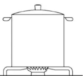
natural_image
Line drawing of a cooking pot on a stove (no text or symbols)FIG. 2
USO
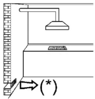
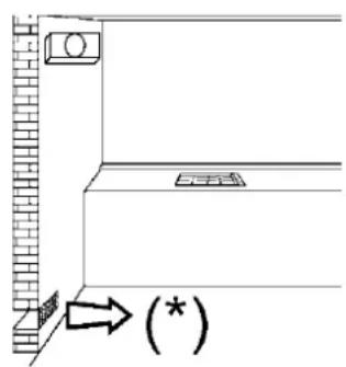
FIG. 3 FIG. 4 FIG. 5
LIMPIEZA
ATENCIÓN:
natural_image
Isometric line drawing of a kitchen cabinet with a gas stove on top (no text or symbols)
INSTALACIÓN
natural_image
Close-up of a mechanical testing setup with a tool inserted into a circular component, surrounded by cylindrical components and mounting holes (no visible text or symbols)
FIG. 12/AFIG. 12
TRANSFORMACIONES
FIG. 15
natural_image
Metallic electronic component with multiple slots and a central slot, placed on a tiled floor (no visible text or symbols)FIG. 16 FIG. 17 FIG. 18


MANTENIMIENTO
Σ Qn Natural Gas = 7.8 kW
Σ Qn LPG Gas = 567 (G30)
557 (G31)
Σ Qn Natural Gas = 6.95 kW
Σ Qn LPG Gas = 505 (G30)
496 (G31)
Σ Qn Natural Gas = 9.55 kW
Σ Qn LPG Gas = 694 (G30)
682 (G31)
Σ Qn Natural Gas = 9.65 kW
Σ Qn LPG Gas = 9.75 kW
Σ Qn LPG Gas = 709 (G30)
696 (G31)
Σ Qn Natural Gas = 10.85 kW
Σ Qn LPG Gas = 10.95 kW
Σ Qn LPG Gas = 796 (G30)
782 (G31)
Σ Qn Natural Gas = 11.95 kW
Σ Qn LPG Gas = 11.70 kW
Σ Qn LPG Gas = 851 (G30)
836 (G31)
Instructions for the installation and advice for the maintenance
CGW LUX 60 3G AI AL TR CI - CGW LUX 60 4G AI AL CI CGW LUX 60 4G AI AL TR CI - CGW LUX 70 5G AI AL TR CI CGW LUX 70 5G AI AL CI - CGW LUX 90 5G AI AL DR CI
Instructions Manual
CGW LUX 60 3G AI AL TR CI - CGW LUX 60 4G AI AL CI CGW LUX 60 4G AI AL TR CI - CGW LUX 70 5G AI AL TR CI CGW LUX 70 5G AI AL CI - CGW LUX 90 5G AI AL DR CI
natural_image
Black gas stove burner with multiple burners and heat sinks (no text or symbols visible)These instructions are only valid if the country symbol appears on the appliance. If the symbol does not appear on the appliance, it is necessary to refer to the technical instructions which will provide the necessary instructions concerning modification of the appliance to the conditions of use of the country.

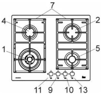
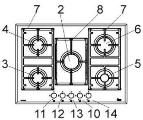
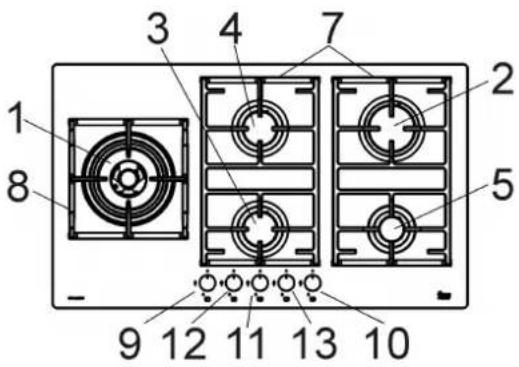
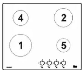
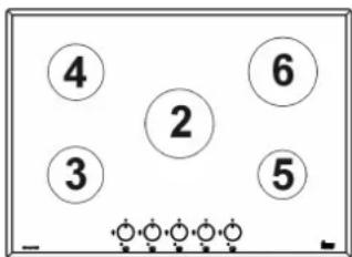
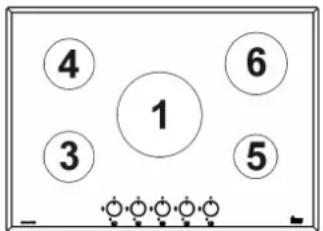
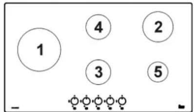
DESCRIPTION OF HOBS
| MODEL: CGW LUX 60 3G AI AL TR CI | MODEL: CGW LUX 60 4G AI AL CI |
 Version UR 4 kW Version UR 4 kW | 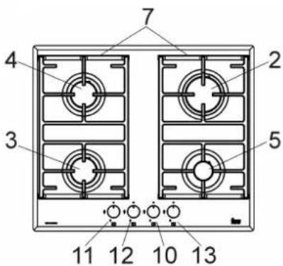 |
| MODEL: CGW LUX 60 4G AI AL TR CI | MODEL: CGW LUX 70 5G AI AL TR CI |
 Version UR 4 kW Version UR 4 kW | 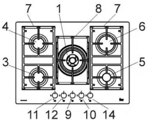 Version UR 4 kW Version UR 4 kW |
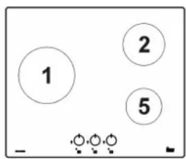
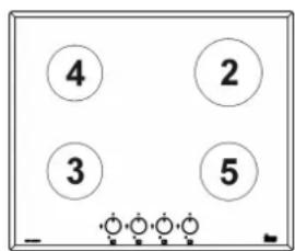
| MODEL: CGW LUX 70 5G AI AL CI | MODEL: CGW LUX 90 5G AI AL DR CI |
 |  Version UR 5 kW Version UR 5 kW |
DESCRIPTION OF HOBS
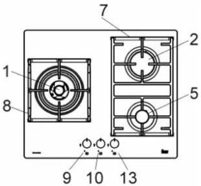
1 Ultra rapid gas burner of 4000 ÷ 5000 W
2 Rapid gas burner of 2800 W
3 Semirapid gas burner reduced of 1400 W
4 Semirapid gas burner of 1750 W
5 Auxiliary gas burner of 1000 W
6 Rapid gas burner of 2700 ÷ 2800 W
7 Enamelled cast iron two-burner pan support
8 Enamelled cast iron ultra rapid gas burner
9 Burner n° 1 control knob
10 Burner n° 5 control knob
11 Burner n° 4 control knob
12 Burner n° 3 control knob
13 Burner n° 2 control knob
14 Burner n° 6 control knob
Attention: this appliance has been manufactured for domestic use only and it employment by private person.
This cook top was designed to be used exclusively as a cooking appliance: any other use (such as heating rooms) is to be considered improper and dangerous.
USE
1) BURNERS
A diagram is screen-printed above each knob on the front panel. This diagram indicates to which burner the knob in question corresponds. After having opened the gas mains or gas bottle tap, light the burners as described below:
- automatic electrical ignition
Push and turn the knob corresponding to the required burner in an anticlockwise direction until it reaches the full on position (large flame fig. 1), then depress the knob.
- Lighting burners equipped with flame failure device
The knobs of burners equipped with flame failure device must be turned in an anticlockwise direction until they reach the full on position (large flame fig. 1) and come to a stop. Now depress the knob in question and repeat the previously indicated operations.
Keep the knob depressed for about 10 seconds once the burner has ignited.
As far as the models equipped with the griddle are concerned, do not keep the ignition system activated for more than 15 seconds; if after 15 seconds the burner is not switched on jet, switch off the ignition and wait for at least 1 minute before trying again.
With regards to all the models, in case of accidental extinguishment of the flame, disengage the ignition by rotating the knob to the off position. Wait at least 1 minute before re-igniting the flame.
HOW TO USE THE BURNERS
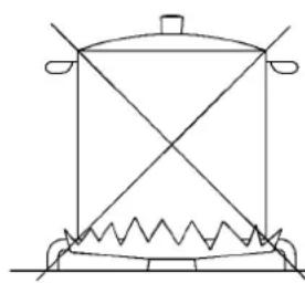
Bear in mind the following indications in order to achieve maximum efficiency with the least possible gas consumption:
- use adequate pans for each burner (consult the following table and fig. 2).
- When the pan comes to the boil, set the knob to the reduced rate position (small flame fig. 1).
- Always place a lid on the pans.
- Use only pan with a flat bottom.
Burners Power W Pan ∅ in cm
| Ultrarapid | 4000 ÷ 5000 24 ÷ 26 |
| Rapid | 2700 ÷ 2800 20 ÷ 22 |
| Semirapid reduced | 1400 16 ÷ 18 |
| Semirapid | 1750 16 ÷ 18 |
| Auxiliary | 1000 10 ÷ 14 |
WARNINGS:
- burners with flame failure device may only be ignited when the relative knob has been set to the Full on position (large flame fig. 1).
- Matches can be used to ignite the burners in a blackout.
- Never leave the appliance unattended when the burners are being used. Make sure there are no children in the near vicinity. Particularly make sure that the pan handles are correctly positioned and keep a check on foods requiring oil and grease to cook since these products can easily catch fire.
- The machine must not be used by people (including children) with impaired mental or physical capacities, or without experience of using electrical devices, unless supervised or instructed by an expert adult responsible for their care and safety. Children should not be allowed to play with the equipment.
- Never use aerosols near the appliance when it is operating.
- If the built-in hot plate has a lid, any spilt food should be immediately removed from this before it is opened. If the appliance has a glass lid, this could shatter when the hot plate becomes hot. Always switch off all the burners before closing the lid.
- Containers wider than the unit are not recommended.
Closed position
Full on position

Reduced rate position ⬤
FIG. 1
natural_image
Line drawing of a cooking pot with a wavy base and two handles (no text or symbols)
natural_image
Line drawing of a cooking pot on a stand with a coiled base (no text or symbols)FIG. 2
USE
WARNINGS AND ADVICE FOR THE USER:
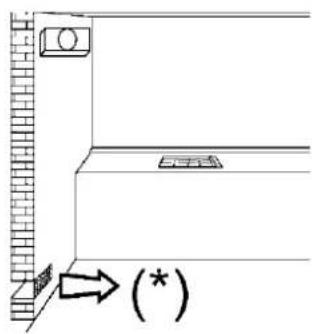
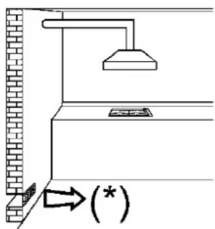
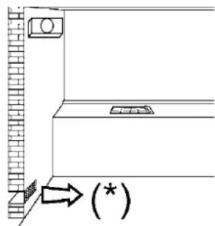
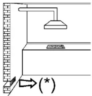
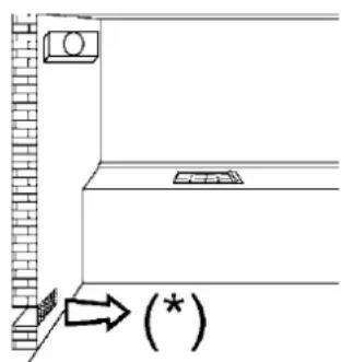
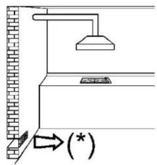
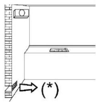
- use of a gas cooking appliance produces heat and moisture in the room in which it is installed. The room must therefore be well ventilated by keeping the natural air vents clear (see fig. 3) and by activating the mechanical aeration device (suction hood or electric fan fig. 4 and fig. 5).
- Intensive and lengthy use of the appliance may require additional ventilation. This can be achieved by opening a window or by increasing the power of the mechanical exhausting system if installed.
- Do not attempt to change the technical characteristics of the product because it can be dangerous.
- If you should not to use this appliance any more (or replace an old model), before disposing of it, make it inoperative in conformity with current law on the protection of health and the prevention of environmental pollution by making its dangerous parts harmless, especially for children who might play on an abandoned appliance.
- Do not touch the appliance with wet or damp hands or feet.
- Do not use the appliance barefoot.
- The manufacturer will not be liable for any damage resulting from improper, incorrect or unreasonable use.
- During, and immediately after operation, some parts of the cook top are very hot: avoid touching them.
- After using the cook top, make sure that the knob is in the closed position and close the main tap of the gas supply or gas cylinder.
- If the gas taps are not operating correctly, call the Service Department.
WARNING: during operation the work surfaces of the cooking area become very hot: keep children away!
(*) AIR INLET: SEE INSTALLATION CHAPTER (PARAGRAPHS 5 AND 6)
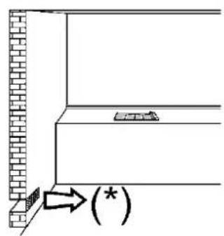
FIG. 3 FIG. 4 FIG. 5


CLEANING
IMPORTANT:
always disconnect the appliance from the gas and electricity mains before carrying out any cleaning operation.
2) HOT PLATE
Periodically wash the hot plate, the enamelled stell pan support, the enamelled burner caps "C" and the burner heads "M" (see fig. 6) with lukewarm soapy water. Following this, all parts should be thoroughly rinsed and dried. Never wash them while they are still warm and never use abrasive powders.
Do not allow vinegar, coffee, milk, salted water, lemon or tomato juice from remaining in contact with the enamelled surfaces for long periods of time.
WARNINGS:
comply with the following instructions, before remounting the parts:
- check that burner heads slots (see fig. 6) have not become clogged by foreign bodies.
- Check that enamelled burner cap "C" (fig. 6) have correctly positioned on the burner head. It must be steady.
- Do not force the taps if they are difficult open or close. Contact the technical assistance service for repairs.
- Don't use steam jets for the equipment cleaning.
Note: continuous use could cause the burners to change colour due to the high temperature.
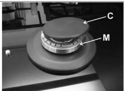
FIG. 6

INSTALLATION
TECHNICAL INFORMATION FOR THE INSTALLER
Installation, adjustments of controls and maintenance must only be carried out by a qualified engineer.
The appliance must be correctly installed in conformity with current law and the manufacturer's instructions.
Incorrect installation may cause damage to persons, animals or property for which the Manufacturer shall not be considered responsible.
During the life of the system, the automatic safety or regulating devices on the appliance may only be modified by the manufacturer or by his duly authorized dealer.
CAUTION:
do not place the glass directly on the unit. The bottom of the hob must rest on the unit.
3) INSTALLING THE HOT PLATE
Check that the appliance is in a good condition after having removed the outer packaging and internal wrappings from around the various loose parts. In case of doubt, do not use the appliance and contact qualified personnel.
Never leave the packaging materials (cardboard, bags, polystyrene foam, nails, etc.) within children's reach since they could become potential sources of danger.
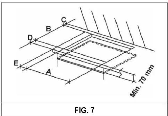
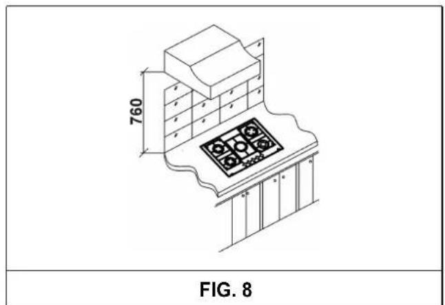
The measurements of the opening made in the top of the modular cabinet and into which the hot plate will be installed are indicated in either fig. 7. Always comply with the measurements given for the hole into which the appliance will be recessed (see fig. 7 and 8)
The appliance belongs to class 3 and is therefore subject to all the provisions established by the provisions governing such appliances.
IMPORTANT!
A perfect installation, adjustment or transformation of the cook top to use other gases requires a QUALIFIED INSTALLER: a failure to follow this rule will void the warranty.
COMPLY WITH THE DIMENSIONS (in mm)
| A B C D | E | ||||
| 3F - 4F (60) | 553 | 473 | 63.5 | 63.5 | 63.5 min. |
| 5F (70) | 553 | 473 | 63.5 | 63.5 | 173.5 min. |
| 5F (90) | 833 | 475 | 62.5 | 62.5 | 73.5 min. |
INSTALLATION
4) FIXING THE HOT PLATE
The hot plate has a special seal which prevents liquid from infiltrating into the cabinet. Strictly comply with the following instructions in order to correctly apply this seal:
- take off all the movable parts of the hob.
- Cut the seal in 4 parts of the necessary lenght to positioning it on the 4 edges of the crystal.
-
Overturn the hot plate and correctly position seal "E" (fig. 9) under the edge of the hot plate itself, so that the outer side of the seal perfectly matches the outer perimetral edge of the crystal. The ends of the strips must fit together without overlapping.
-
Evenly and securely fix the seal to the crystal, pressing it in place with the fingers.
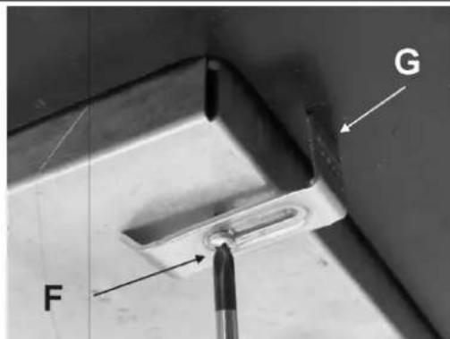
- Position the hob in the hole in the unit and fasten it in place using the appropriate screws "F" of the fastening hooks "G" (see fig. 10).
- In order to avoid accidental touch with the overheating bottom of the hob, during the working, is necessary to put a wooden insert, fixed by screws, at a minimum distance of 70 mm from the top (see fig. 7).
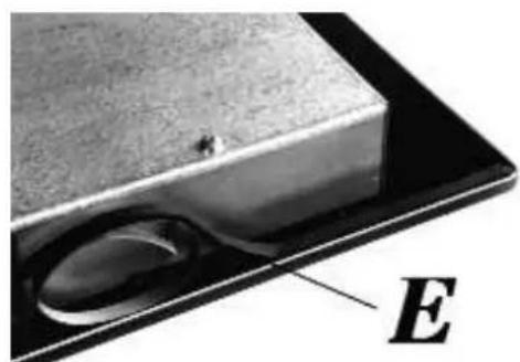
FIG. 9 FIG. 10

INSTALLATION
IMPORTANT INSTALLATION INSTRUCTIONS
The installer should note that the appliance that side walls should be no higher than the hot plate itself. Furthermore, the rear wall, the surfaces surrounding and adjacent to the appliance must be able to withstand an overtemperature of 65 K.
The adhesive used to stick the plastic laminate to the cabinet must be able to withstand a temperature of not less than 150 °C otherwise the laminate could come unstuck.
The appliance must be installed in compliance with BS 6172 1990, BS 5440 part. 2 1989 and BS 6891 1988.
This appliance is not connected to a device able to dispose of the combustion fumes. It must therefore be connected in compliance with the above mentioned installation standards. Particular care should be paid to the following provisions governing ventilation and aeration.
5) ROOM VENTILATION
To ensure correct operation of the appliance, it is important to ensure that the room where the hot plate is installed has sufficient ventilation, as set out in BS 5440 part 2. 1989. See table below.
| Type of appliance | Volume of room cubic metres | Min. size of vent sq. cm. | Openable window or alternative method of venting to the outside |
| Domestic ovens hotplates or any combinations | 5 | 100 | yes |
| 5 to 10 | 50 | yes | |
| 11 to 20 | nil | yes | |
| 20 and above | nil | yes |
Natural air flow must enter directly through permanent openings in the walls of the room in question. These must open towards the outside and possess a minimum section of 100 cm^2 see fig. 3). It must be impossible to obstruct these openings.
Indirect ventilation with air drawn from adjacent rooms is permitted in strict compliance with the provisions in force.
6) LOCATION AND AERATION
Gas cooking appliances must always dispose of their combustion fumes through hoods. These must be connected to flues, chimneys or straight outside (see fig. 4). If it is not possible to install a hood, an electric fan can be installed on a window or on a wall facing outside (see fig. 5). This must be activated at the same time as the appliance, so long as the specifications in the provisions in force are strictly complied with.
7) GAS CONNECTION
Before connecting the appliance, check that the values on the data label affixed to the underside of the hot plate correspond to those of the gas mains in the home.
A label on the appliance indicates the regulating conditions: type of gas and working pressure.
WARNING:
a gas hot plate can only be connected by a CORGI Registered engineer.
Installations should be carried out in accordance with BS 6891 1988 and must comply with the Gas Safety Regulations.
All hot plate installations must include an isolation tap.
GAS PRESSURE TEST
Some hot plates models have a test point fitted under the control panel, to conduct a gas pressure test proceed as follows:
- turn off the gas supply.
- Remove screw in the pressure test point, place test gauge connecting tube on test point.
- Fit a burner ring and cap onto burner assembly, replace control knob onto corresponding control tap for the burner.
- Turn on gas and ascertain working pressure. After test, turn off control tap, turn off gas supply, disconnect test gauge connecting tube.
Replace the test point screw, turn gas back on and test for soundness. Reassemble the hotplate.
IMPORTANT:
the appliance complies with the provisions of the following CEE Directives:
2009/142 + 93/68 regarding gas safety.
INSTALLATION
IMPORTANT: the appliance must be installed following the manufacturer's instructions. The manufacturer will not be liable for injury to persons or animals or property damage caused by an incorrect installation.
The electrical connections of the appliance must be carried out in compliance with the provisions and standards in force.
Before connecting the appliance, check that:
- the voltage matches the value shown on the specification plate and the section of the wires of the electrical system can support the load, which is also indicated on the specification plate.
- the electrical capacity of the mains supply and current sockets suit the maximum power rating of the appliance (consult the data label applied to the underside of the hot plate).
- the socket or system has an efficient earth connection in compliance with the provisions and standards in force. The manufacturer declines all responsibility for failing to comply with these provisions.
When the appliance is connected to the electricity main by a socket:
- fit a standard plug "C" suited to the load indicated on the data label to the cable. Fit the wires following figure 11, taking care of respecting the following correspondences:
Letter L (live) = brown wire;
Letter N (neutral) = blue wire;
earth symbol ≡ green - yellow wire.
- The power supply cable must be positioned so that no part of it is able to reach an overtemperature of 75 K.
- Never use reductions, adapters of shunts for connection since these could create false contacts and lead to dangerous overheating.
- The outlet must be accessible after the built-in.
When the appliance is connected straight to the electricity main: -
install an omnipolar circuit-breaker between the appliance and the electricity main. This circuit-breaker should be sized, in compliance with current installation regulations.
-
Remember that the earth wire must not be interrupted by the circuit-breaker.
- For optimum safety, the electrical connection may also be protected by a high sensitivity differential circuit-breaker.
You are strongly advised to fix the relative yellow-green earth wire to an efficient earthing system. Before performing any service on the electrical part of the appliance, it must absolutely be disconnected from the electrical network.
If the installation requires modifications to the home's electrical system or if the socket is incompatible with the appliance's plug, have changes or replacements performed by professionally-qualified person. In particular, this person must also make sure that the section of the wires of the socket is suitable for the power absorbed by the appliance.
WARNINGS:
all our appliances are designed and manufactured in compliance with European standards EN 60 335-1, EN 60 335-2-6 and EN 60 335-2-102 plus the relative amendments. The appliance complies with the provisions of the following CEE Directives:
- CEE 2004/108/CE regarding to electromagnetic compatibility.
- CEE 2006/95 regarding electrical safety.
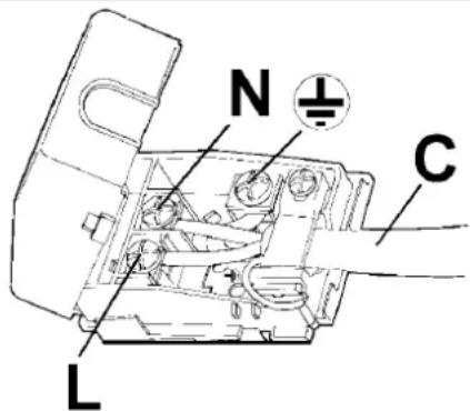
FIG. 11
CONVERSIONS
Always disconnect the appliance from the electricity main before making any adjustments. All seals must be replaced by the technician at the end of any adjustments or regulations. Our burners do not require primary air adjustment.
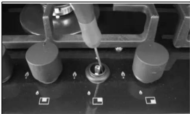
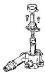
9) TAPS
"Reduced rate" adjustment
- Switch on the burner and turn the relative knob to the "Reduced rate" position (small flame fig. 1).
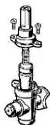
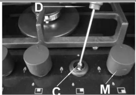
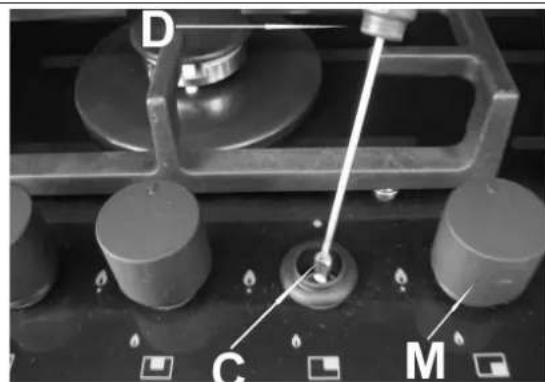
- Remove knob "M" (fig. 12 and 12/A) of the tap, which is simply pressed on to its rod. The by-pass for minimal rate regulation can be: beside the tap (fig. 12) or inside the shaft. In any case, to access to regulation, it can be done trough the insertion of a small screwdriver "D" beside the tap (fig. 12) or in the hole "C" inside the shaft of the tap (fig 12/A). Turn the throttle screw to the right or left until the burner flame has been adequately regulated to the "Reduced rate" position.
The flame should not be too low: the lowest small flame should be continuous and steady. Re-assemble the several components.
It is understood that only burners operating with G20 gas should be subjected to the above mentioned adjustments. The screw must be fully locked when the burners operate with G30 or G31 (turn clockwise).
natural_image
Close-up of a mechanical testing setup with a tool and three cylindrical components on a dark surface (no visible text or symbols)FIG. 12 FIG. 12/A


CONVERSIONS
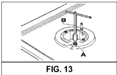
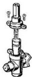
10) REPLACING THE INJECTORS
technician must reset any seals on the regulating or pre-regulating devices.
The burners can be adapted to different types of gas by mounting injectors suited to the type of gas in question do this, first remove the burner tops using a wrench "B" Now unscrew injector "A" (see fig. 13) and fit a injector corresponding to the utilized type of gas in its place.
The envelope with the injectors and the labels can be included in the kit, or at disposal to the authorized customer Service Centre.
It is advisable to strongly tighten the injector in place. After the injectors have been replaced, the burners must be regulated as explained in paragraphs 9. The
For the sake of convenience, the nominal rate table also lists the heat inputs of the burners, the diameter of the injectors and the working pressures of the various types of gas.
BURNER ARRANGEMENT ON THE HOT PLATE
TABLE
| BURNERS | GAS | NORMAL PRESSURE mbar | NORMAL RATE | INJECTOR DIAMETER Max1/100 mm | NOMINAL HEAT INPUT (W) | |||
| N° | DESCRIPTION | g/h l/h Min. | ||||||
| 1 | ULTRA RAPID (Version 5 kW) | G30 - BUTAN | 28 - 30 | 345 | 476 | 2 x 72 B + 46 B | 1800 | 4750 |
| G31 - PROPAN | 37 | 339 | 2 x 72 B + 46 B | 1800 | 4750 | |||
| G20 - NATURAL | 20 | 2 x 115 A + 71 A | 1800 | 5000 | ||||
| 1 | ULTRA RAPID (Version 4 kW) | G30 - BUTAN | 28 - 30 | 291 | 381 | 100 B | 1800 | 4000 |
| G31 - PROPAN | 37 | 286 | 100 B | 1800 | 4000 | |||
| G20 - NATURAL | 20 | 145 A | 1800 | 4000 | ||||
| 2 | RAPID | G30 - BUTAN | 28 - 30 | 204 | 267 | 83 | 800 | 2800 |
| G31 - PROPAN | 37 | 200 | 83 | 800 | 2800 | |||
| G20 - NATURAL | 20 | 117 Y | 800 | 2800 | ||||
| 3 | SEMIRAPID REDUCED | G30 - BUTAN | 28 - 30 | 102 | 133 | 58 | 550 | 1400 |
| G31 - PROPAN | 37 | 100 | 58 | 550 | 1400 | |||
| G20 - NATURAL | 20 | 85 Y | 550 | 1400 | ||||
| 4 | SEMIRAPID | G30 - BUTAN | 28 - 30 | 127 | 167 | 68 | 550 | 1750 |
| G31 - PROPAN | 37 | 125 | 68 | 550 | 1750 | |||
| G20 - NATURAL | 20 | 98 Z | 550 | 1750 | ||||
| 5 | AUXILIARY | G30 - BUTAN | 28 - 30 | 73 | 95 | 51 | 450 | 1000 |
| G31 - PROPAN | 37 | 71 | 51 | 450 | 1000 | |||
| G20 - NATURAL | 20 | 75 X | 450 | 1000 | ||||
| 6 | RAPID | G30 - BUTAN | 28 - 30 | 204 | 257 | 83 | 800 | 2800 |
| G31 - PROPAN | 37 | 200 | 83 | 800 | 2800 | |||
| G20 - NATURAL | 20 | 117 S | 800 | 2700 | ||||
SERVICING
Always disconnect the appliance from the electricity and gas mains before proceeding with any servicing operation.
11) REPLACING HOT PLATE PARTS
Replacement of the components housed inside the appliance: remove the trivets and the burners from the upper part of the working table; remove the fixing screws "V" of the burner (fig. 14) and the knobs fixed by pressure with the hans, in order to take off the appliance.
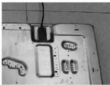
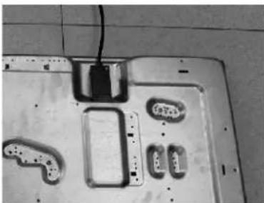
After having carried out the above listed operations, taps (fig. 15) and electrical components can all be replaced (fig. 16).
It is advisable to change seal "D" whenever a tap is replaced to ensure a perfect tightness.
Greasing the taps (see fig. 17 - 18)
If a tap becomes stiff to operate, it must be immediately greased in compliance with the following instructions:
- remove the tap.
- Clean the cone and its housing using a cloth soaked in diluent.
- Lightly spread the cone with the relative grease.
- Fit the cone back in place, operate it several times and then remove it again. Eliminate any excess grease and check that the gas ducts have not become clogged.
- Fit all parts back in place, complying with the demounting order in reverse.
- The tight closure test must be done using a foamy liquid. The use of the flame is prohibited.
To facilitate the servicing technician's task, here is a chart with the types and sections of the powering cables and the ratings of the electrical components.
WARNING:
PERFORMED BY AUTHORISED PERSONS.

FIG. 14

FIG. 15
natural_image
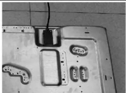
Close-up of a mechanical or electronic component with multiple small components and a central black block (no visible text or symbols)FIG. 16 FIG. 17
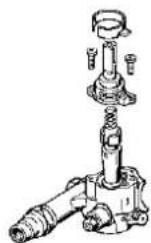
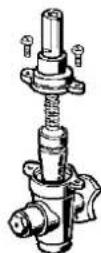
FIG. 18

SERVICING
CABLE TYPES AND SECTIONS
| TYPE OF TYPE OF SINGLE - PHASE HOT PLATE CABLE POWER SUPPLY | |
| Gas hot plate H05 RR-F Section 3 x 0.75 mm | 2 |
ATTENTION!!!
If the power supply cable is replaced, the installer should leave the ground wire longer than the phase conductors (fig. 19) and comply with the recommendations given in paragraph 8.

TECHNICAL DATA ON THE DATA LABEL
3 BURNERS (60) (UR LEFT - Version 4 kW)
Category II_2H3+
G 30 - Butane 28 - 30 mbar
G 31 - Propane 37 mbar
G 20 - Natural 20 mbar
Σ Qn Natural Gas rate = 7.8 kW
Σ Qn LPG Gas rate = 567 (G30)
557 (G31)
Voltage = 220 - 240 V \~
Frequency = 50/60 Hz
4 BURNERS (60)
Σ Qn Natural Gas rate = 6.95 kW
Σ Qn LPG Gas rate = 505 (G30)
496 (G31)
Voltage = 220 - 240 V \~
Frequency = 50/60 Hz
4 BURNERS (60)
(UR LEFT - Version 4 kW)
Category II_2H3 +
G 30 - Butane 28 - 30 mbar
G 31 - Propane 37 mbar
G 20 - Natural 20 mbar
Σ Qn Natural Gas rate = 9.55 kW
Σ Qn LPG Gas rate = 694 (G30)
682 (G31)
Voltage = 220 - 240 V \~
Frequency = 50/60 Hz
5 BURNERS (70)
Category II_2H3 +
G 30 - Butane 28 - 30 mbar
G 31 - Propane 37 mbar
G 20 - Natural 20 mbar
Σ Qn Natural Gas rate = 9.65 kW
Σ Qn LPG Gas rate = 9.75 kW
Σ Qn LPG Gas rate = 709 (G30)
696 (G31)
Voltage = 220 - 240 V \~
Frequency = 50/60 Hz
5 BURNERS (70)
(UR CENTRAL - Version 4 kW)
Σ Qn Natural Gas rate = 10.85 kW
Σ Qn LPG Gas rate = 10.95 kW
Σ Qn LPG Gas rate = 796 (G30)
782 (G31)
Voltage = 220 - 240 V \~
Frequency = 50/60 Hz
5 BURNERS (90)
(UR LEFT - Version 5 kW)
Category II_2H3 +
G 30 - Butane 28 - 30 mbar
G 31 - Propane 37 mbar
G 20 - Natural 20 mbar
Σ Qn Natural Gas rate = 11.95 kW
Σ Qn LPG Gas rate = 11.70 kW
Σ Qn LPG Gas rate = 851 (G30)
836 (G31)
Voltage = 220 - 240 V \~
Frequency = 50/60 Hz
GB
TECHNICAL DATA FOR THE APPLIANCE GAS REGULATION
| Cet appareil doit être installéconformement aux reglementationsen viguer et utilisé seulement dans unendroit bien aeré.Consultar les notices avant d'installeret d'utiliser cet appareil.Pour autre type de gaz, il faut operercomme decrit dans la notice d'emploi.Cet appareil est réglé pourfonctionner à: | Este aparato debe ser montadoconforme a los reglamentos vigentesy utilizado solamente en un ambienteadecuadamente aireado.Antes de installar o utilizar elaparato, consultar los manuales deinstrucción.Este aparato está regulado parafuncionar a:ES | Este produto deve ser instalado emconformidade com as normas desegurança em vigor e usado somente emum ambiente dotado de adequadaventilação. Antes de proceder instalação e uso do aparelho, consultaros respectivos manuais de instruções.Para outro tipo de gás proceder comoindicado nas instruções de instalação euso.Este aparelho está ajustadopara operar em: |
| Η συσκευή autή μπορεί ναεγκατασταθει καινο λειτουργει μόνο σεχώρους διαρκώς αεριζόμενουςσύμφωνα με τον κανονισμό.Συμβουλευτείτε το εγχειρίδιο οδηγιώνπρην την εγκατάσταση της συσκευήσαυτής.Για όλλο τύπο αερίου εφαρμόστε ά,ηαναφέρεται στο εγχειρίδιο οδηγιών.Η συσκευή autή έχειρυθμιστεί για να λειτουργεισε:GR | This appliance must be installed incompliance with the current provisions inforce and only used in rooms equippedwith adequate ventilation. Consult theinstruction manual before proceedingwith installation or use of the appliance.for another type of gas, operate asdescribed in the directions for theinstallation and use.This household appliance is adjustedto work at:GB | |
| G30 - "p" 28-30 mbar / G31 - "p" 37 mbar 3+COD. 0030684E1 - 04/12 | ||
TECHNICAL ASSISTANCE AND SPARE PARTS
Before leaving the factory, this appliance will have been tested and regulated by expert and specialized personnel in order to guarantee the best performances.
Any repairs or adjustments which may be subsequently required may only be carried out by qualified personnel with the utmost care and attention.
For this reason, always contact your Dealer or our nearest After Sales Service Center whenever repairs or adjustments are required, specifying the type of fault and the model of the appliance in your possession.
Please also note that genuine spare parts are only available from our After Sales Service Centers and authorized retail outlets.
The above data are printed on the data label put on the inferior part of the appliance and on the packing label.
The above informations give to the technical assistant the possibility to get fit spare parts and a heaven-sent intervention. We suggest to fill the table below.
MARK:
MODEL:
SERIES:
natural_image
Black industrial gas stove with multiple burners and cooling fans (no visible text or labels)natural_image
Simple line drawing of a cooking pot with a wavy base and two handles (no text or symbols)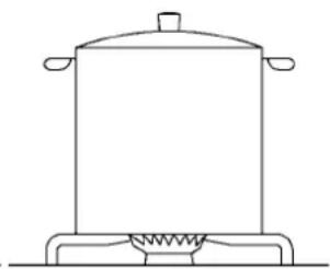
natural_image
Line drawing of a cooking pot on a stand with a heating element (no text or symbols)FIG. 2
UTILISATION
AVERTISSEMENTS ET CONSEILS D'UTILISATION:
FIG. 3 FIG. 4 FIG. 5
NETTOYAGE
ATTENTION:
natural_image
Isometric line drawing of a kitchen appliance with a stove and cabinet (no text or symbols)FIG. 8
INSTALLATION
4) FIXATION DE LA TABLE DE CUISSON
natural_image
Close-up of a metallic object with a curved indentation and a labeled point E (no text or symbols on the object itself)FIG. 9
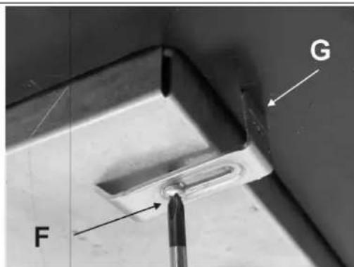
FIG. 10
INSTALLATION
PRESCRIPTIONS IMPORTANTES POUR L'INSTALLATION
FIG. 11
REGLAGES
natural_image
Close-up of a mechanical testing setup with a tool inserted into a cylindrical component, surrounded by circular components and flame indicators (no visible text or symbols)FIG. 12 FIG. 12/A
TRANSFORMATIONS
10) REMPLACEMENT DES BUSES
FIG. 15
natural_image
Interior view of a computer mouse with multiple electronic components and a black clip (no visible text or symbols)FIG. 16 FIG. 17
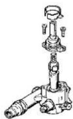

FIG. 18
ENTRETIEN
TYPES ET SECTIONS DES CABLES D'ALIMENTATION
| TYPE DE TABLE TYPE DE TABLE | ALIMENTATIONMONOPHASE |
| Table de cuisson au gaz H05 RR-F Section 3 x 0.75 mm | 2 |
ATTENTION !!!
natural_image
Black plastic gas stove with multiple burners and cooling fans (no text or symbols visible)
natural_image
Line drawing of a cooking pot with a wavy base and two handles (no text or symbols)
natural_image
Line drawing of a cooking pot on a heating element (no text or symbols)EIK. 2
ΧΡΗΣΗ
EIK. 3 EIK. 4 EIK. 5
ΚΑΘΑΡΙΣΜΑ
ΠΡΟΣΟΧΗ:
natural_image
Isometric line drawing of a kitchen appliance with a stove and cabinet (no text or symbols)
ΕΓΚΑΤΑΣΤΑΣΗ
natural_image
Close-up of a metallic object with a circular indentation and labeled point E (no text or symbols beyond label)EIK. 9
EIK. 10
ΕΓΚΑΤΑΣΤΑΣΗ
natural_image
Close-up of a mechanical testing setup with a tool and three cylindrical components on a dark surface (no visible text or symbols)EIK. 12 EIK. 12/A
ΜΕΤΑΤΡΟΠΕΣ
FIG. 13
ΠΙΝΑΚΑΣ
EIK. 15
natural_image
Metallic electronic component with multiple slots and a small rectangular slot, placed on a tiled floor (no visible text or symbols)EIK. 16
EIK. 17
EIK. 18
ΣΥΝΤΗΡΗΣΗ
natural_image
Black plastic gas stove with multiple burners and vented top (no text or symbols visible)These instructions are only valid if the country symbol appears on the appliance. If the symbol does not appear on the appliance, it is necessary to refer to the technical instructions which will provide the necessary instructions concerning modification of the appliance to the conditions of use of the country.

natural_image
Line drawing of a cooking pot with a wavy base and two handles (no text or symbols)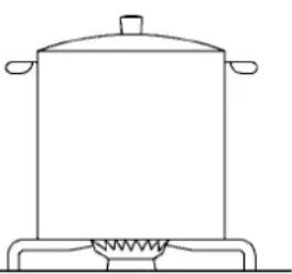
natural_image
Line drawing of a cooking pot on a stand (no text or symbols)FIG. 2
UTILIZAÇÃO
AVISOS E RECOMENDAÇÕES PARA O UTILIZADOR:
FIG. 3 FIG. 4 FIG. 5

LIMPEZA
ATENÇÃO:
natural_image
Isometric line drawing of a kitchen appliance with a stove and cabinet (no text or symbols)FIG. 8
INSTALAÇÃO
4) FIXAÇÃO DA PLACA
natural_image
Close-up of a metallic object with a circular indentation and a labeled point E (no text or symbols on the object itself)FIG. 9
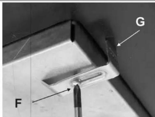
FIG. 10

INSTALAÇÃO
natural_image
Close-up of a mechanical testing setup with a tool inserted into a cylindrical component, surrounded by circular components and no visible text or symbols.FIG. 12 FIG. 12/A


TRANSFORMAÇÕES
10) SUBSTITUIÇÃO DOS INJECTORES
To facilitate the servicing technician's task, here is a chart with the types and sections of the powering cables and the ratings of the electrical components.
NOTA: A MANUTENÇÃO DEVE SER EFECTUADA
APENAS POR PESSOAL AUTORIZADO
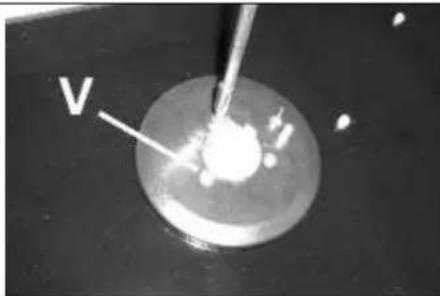
FIG. 14
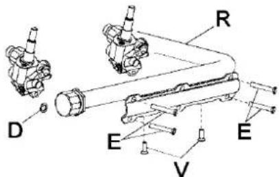
FIG. 15
natural_image
Close-up of a mechanical component with multiple small electronic parts and a central black block (no visible text or symbols)FIG. 16 FIG. 17
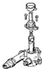

FIG. 18