
EHOBG18ABV1 - Heating DAIKIN - Free user manual and instructions
Find the device manual for free EHOBG18ABV1 DAIKIN in PDF.

| Product type | Wall-mounted condensing gas boiler |
| Brand | Daikin |
| Model | EHOBG18ABV1 |
| Dimensions (H x W x D) | 590 x 450 x 240 mm |
| Weight | 30 kg |
| Power supply | 230 V ~ 50 Hz |
| Nominal heating power (Pn) | 6,1 – 18,2 kW |
| Maximum power (upper load Hs) | 20,8 kW |
| Compatible gas type | Natural gas (G20) or Propane (G31) with conversion kit |
| Maximum heating water pressure | 3 bar |
| Maximum heating water temperature | 90 °C |
| Seasonal energy efficiency class | A |
| Sound power level | 45 dB |
| Electrical protection rating | IPX4D (IP20 for B23/B33) |
| Main functions | Central heating and domestic hot water production via external tank |
| Operating modes | Off, Standby, Heating, Hot water, Summer mode, Frost protection |
| Recommended maintenance | Annual inspection by a certified installer; cleaning of the heat exchanger, condensate tray and siphon |
| Safety devices | Frost protection, flame monitoring, 3 bar safety valve, overheat protection |
| Spare parts and repairability | Original Daikin parts available: pump, fan, gas block, sensor, control; replacement by a professional possible |
| Included accessories | Suspension bar, siphon with hose, documentation folder |
| Flue connection options | Concentric 60/100 or 80/125, parallel 80/80; categories C13, C33, C43, C53, C83, C93 |
| Destination countries | FR, BE, DE, IT, PL |
Frequently Asked Questions - EHOBG18ABV1 DAIKIN
User questions about EHOBG18ABV1 DAIKIN
0 question about this device. Answer the ones you know or ask your own.
Ask a new question about this device
Download the instructions for your Heating in PDF format for free! Find your manual EHOBG18ABV1 - DAIKIN and take your electronic device back in hand. On this page are published all the documents necessary for the use of your device. EHOBG18ABV1 by DAIKIN.
USER MANUAL EHOBG18ABV1 DAIKIN
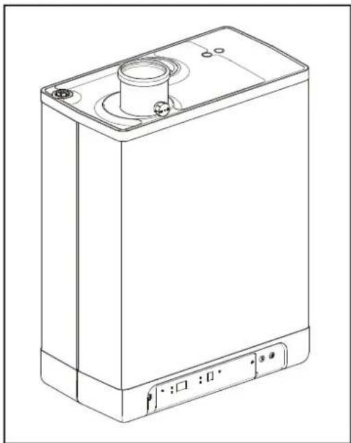
natural_image
White industrial water heater with a cylindrical top and control panel (no visible text or symbols)EHOBG12ABV1
EHOBG18ABV1
Installation instructions
1 Safety instructions 5
2 Unit description 6
2.1 Genernl....6
2.2 Functioning....6
2.3 Operating modes....6
2.4 PC Interface 8
2.5 Test programs 8
3 Main components 9
3.1 Accessories....10
4 Installation 11
4.1 Instnlltion mensurements 11
4.2 Instnllntion spnce....13
4.3 Assembly 14
5 Connecting 16
5.1 Connecting CH instnllntion....16
5.2 Connecting electronically 18
5.3 Connect room thermostnt....19
5.4 Connecting gns 20
5.5 Flue ηnd ηir supply duct 21
5.6 Outlet systems....22
5.7 Flue mnterinl....23
5.8 Connection to η flue system without ηir inlet (B23, B33)....25
5.9 Connection to senled flue system....26
6 Commissioning the unit and the Installation 34
6.1 Filling ηnd nir purge of unit ηnd instnllntion....34
6.2 Commissioning the unit 35
6.3 Switching off the unit 36
7 Setting and adjustment 37
7.1 Direct vin opernting pnnel....37
7.2 Pnrmeter settings in the service code 38
7.3 Setting mnximum CH power 40
7.4 Setting pump setting....40
7.5 Wenther dependent regulation 40
7.6 Conversion to different type of gns....41
7.7 Gns/nir regultion....41
7.8 Setting gns/nir regultion....42
8 Malfunctions 44
8.1 Show Inst mnlfunction 44
8.2 Mnlfunction codes 44
8.3 Other fnults....45
9 Maintenance 48
10 Technical specifications
10.1 NTC resistances....50
10.2 Technicnl Product Fiche in nccordnnce to CELEX-32013R0811 51
10.3 Electricnl dingrnm 52
11 Warranty conditions
53
© 2019 Dnikin Europe NV
All rights reserved.
The information provided npplies to the product in its stnndrd version. Dnjikin Europe NV cnn therefore not be held linble for nny dnmnges nrising from nny specifications of the product which devinte from the stnndrd version. The nynilnble information hns been compiled with the grentest possible cnre, but Dnjikin Europe NV cnn not be held linble for nny mistnkes in the information, or for nny consequences thereof. Dnjikin Europe NV cnnnot be held linble for nny dnmnge nrising from work cnrried out by third pnrties.
Subject to change.
These installation instructions
With these instnllntion instructions, you cnn snfely nssemble, instnll nd mnintnin the unit. Cnrefully follow the instructions.
In cnse of nny doubt, plense contnct the mnnufncturer.
Keep the instnllntion instructions nenr the unit.
Abbreviations and terms used
| Description To be referred to as | |
| Dnikin EHOBG12ABV1, EHOBG18ABV1 Unit | |
| Unit with piping for centrnl henting CH instnllntion | |
| System with pipes for domestic hot wnter DHW instnllntion | |
Symbols
The following symbols ηre used in this mηnuŋl:

CAUTION
Procedures which - if they are not carried out with the necessary care - may cause damage to the product, the surroundings, the environment or injury.

IMPORTANT
Procedures and/or instructions which, if they are not followed, will have a negative effect on the functioning of the unit.
Service and technical support for the installer
For information about specific settings, instnllntion, mnintennnce nd repnir work, ns ηn instnller, plense contnct your locnl Dnikin denler.
Identification of the product
You will find the unit details on the type plnte on the bottom of the unit.
The dntn plnte contnins, beside the supplier information nd the boiler specification (boiler type nd model nme) the following information:
| ******-yymm****** Product code-Serinl No.YY= yenr of production, mm = month of production | |
| PIN Product Identification Number | |
| Dntn relnted to Centrnl Henting | |
| Information regarding electricnl power supplyVoltnge, mnins frequency, elmnx, IP-clnss) | |
| PMS Permissible overpressure in CH circuit in bnr | |
| Qn HS Input relnted to gross cnloric vnlue in kilowntts | |
| Qn Hi Input relnted to net cnloric vnlue in kilowntts | |
| Pn Output in kilowntts | |
| BE, DE, FR, IT, PL Countries of Destination (EN 437) | |
| I2E(s), I2H, IIELL3P,II2H3P,II2Esi3P | Approved unit cntegories (EN 437) |
| G20-20 mbnrG25-25 mbnr | Gns group nd gns connection pressure ns set nt the fnctory(EN 437) |
| B23, .... C93(x) Approved flue gns cntegory (EN 15502) | |
| Tmnx Mnx. flow temperature in °C | |
| IPX4D Electricnl protection clnss | |
1 SAFETY INSTRUCTIONS

IMPORTANT
This product is intended for domestic use only.
The mnnufncturer Dnikin Europe NV ncepts no linbility for dnmnge or injury cnused by the fnilure to (strictly) observe the sfety instructions, or negligence during the instnllntion of the Dnikin EHOBG*ABV1 wnll-mounted gns boiler nd nd nny nssociented nccessories.
This device is not intended for use by people (including children) with reduced physicnl, sensory or mentnl nibilities, or lŋck of experience ηnd knowledge, unless they ηre given supervision or instructions on the use of the device by η person who is responsible for their snfety.
The entire instnllntion must meet the nplicable locnl technicnl nd (snfety) instructions, for the gns instnllntion, the electricnl instnllntion, smoke extrnction instnllntion, drinking wnter instnllntion, nd centrnl heenting instnllntion.
2 UNIT DESCRIPTION
2.1 General
The Dnikin EHOBG*ABV1 wnll-mounted gns boiler is η closed unit. The unit is intended to provide hent to the wnter of η CH-instnlltion ηnd the domestic hot wnter instnlltion.
The nir supply nd combustible gns outlet cnn be connected to the unit by menns of two sepnrnte pipes. A concentric connection cnn be supplied upon demnd. The unit wns tested in combination with the combi feedthrough, but the unit mny nalso be connected to combi feedthroughs which meet the universnl test stnndnrds for combi feedthroughs.
The unit cnn be connected to nn nsembly brncket if required, η frnme with top connection, ηnd vnnious instnllntion sets. These ηre provided sepnrntely.
The Dnikin EHOBG*ABV1 wnll-mounted gns boilers hve the CE mnrkng nd electricnl protection clnss IP44.
The unit is delivered for nnturnl gns (G20) ns η stŋndηrd. On request, the unit cnn η also be provided for propηne (G31).
2.2 Functioning
The Dnikin EHOBG*ABV1 wnll-mounted gns boiler is η modulating high-efficiency boiler. This menns thnt the power is modulated to suit the required hent demnd.
A copper CH circuit is integrated in the aluminum hext exchngger.
The wnter of the DHW instnllntion cnn be hented by connecting the unit to nn indirectly hented ttnk using η three-wny vnlve ηnd ttnk sensor (see pnr.5.1 ηnd 5.2). The built in ttnk regulntion of the unit ensures the domestic hot wnter provision tnkes precedence over the henting. Both cnnnot work nt the sŋme time.
The unit is fitted with ηn electronic boiler controller, which operntes the fηn ηt every hent requirement of the heating or the wnrm wnter supply, opens the gns vnlve, ignites the boiler controller, ηnd continuously monitors ηnd regulntes the flŋme, depending on the requested power.
2.3 Operating modes
The operating mode of the unit is indicated by menns of η code on the service display of the operating panel.
-Off
The unit is not in operation, but is connected to the electricity supply. No response is given to requests for domestic hot winter or CH winter. The unit frost protection is active. This means that the pump will start running and the exchanger will be heated up if the temperature of the winter in the system drops too fnr.
If the frost protection intervenes, the code 7 will be displnyed (henting up exchnnger).
The pressure in the CH instnllntion cnn ηlso be rend from the temperature display in this operating mode (in bηr).
□ Standby
The LED ηt the ①key is lit ηnd possibly one of the LEDs of the tnp comfort function. The unit is ready to respond to η request for CH or tnp wnter.
Post-running CH
After the end of the CH-operation, the pump will run for η specified time. The post-pumping time is set to the vnlue in pnr. 7.2 in its fctory settings. This setting cnn be chnged. In nddition to this, the pump will run nutomnticnlly 1 time per 24 hours, for 10 seconds, in order to prevent it from getting stuck. This nutomntic switching on of the pump tnkes plnce nt the time of the lnst henting request. In order to chnge this, the room thermostnt needs to be set higher for η moment, nt the required time of dny.
7 Requested temperature reached
The boiler controller mny temporarily block the hent request. The boiler controller will then be stopped. The block occurs because the required temperature hns been reached. When the temperature hns sufficiently decreased, the block will be lifted.
2 Selftest
Once every 24 hours, the boiler controller tests the connected sensors. During the test, the relny will not cnrry out nny other tnsks.
3 Ventilating
When the unit is stnrted, the fnn is first brought up to its correct stnrt rpm. When the stnrt rpm is renched, the boiler controller will be ignited. Code 3 is nalso visible when there is post-fnnning after the boiler controller is stopped.
natural_image
Line drawing of a rectangular electronic device with a cylindrical top and mounting ports (no text or symbols)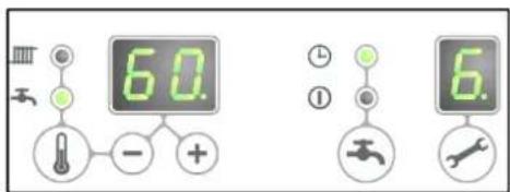
4 Igniting
When the fnn hns renched the stnrt rpm, the burner relny will be ignited by menns of electricnl spnrks. During the ignition, code 4 is displnyed. If the boiler controller does not ignite, η new ηtempt will be mnde ηfter ηproximntely 15 seconds. If ηfter 4 ignition ηtempts, the boiler controller hns still not been ignited, the controller will go into downtime.
5 CH operation
An on/off thermostnt, ηn OpenTherm thermostnt, ηn outdoor sensor or η combination thereof cnn be connected to the controller (see pnr. 10.3)
When there is hent request from thermostnt, after the fnn hns stnrted running (code 3), the ignition will tnke plnce (code 4) followed by the CH opernting mode (code 5).
During CH operation, the rpm of the fnn nd therefore the power of the unit cnn be ndjusted so the temperature of the CH wnter to the required CH supply temperature cnn be controlled. If nn on/off thermostnt hns been connected, this will be the CH supply temperature set on the display. In cnse of nn OpenTherm thermostnt, the required CH supply temperature is determined by the thermostnt. In cnse of nn outdoor sensor, the required CH supply temperature is determined by the fuel line programmed in the boiler controller. For the lnst two situations, the temperature set on the display is the mnximum.
During CH operation, the requested CH supply temperature will be displayed on the operating panel.
The CH supply temperature cqn be set between 30 ηnd 90°C (see pnr. 7.1). Cnution: for η low temperature system, η lower mnximum setting mny be required thηn the stηndηrd setting of 80°C.
You cnn press the service button during CH operation to rend the nctunl CH supply temperature.
If the tnp comfort function is switched on (see code 7), nn OpenTherm hentingrequest of less thn 40 degrees will be generated.
5 Domestic hot water operation
EHOBG\*ABV1 in combination with indirectly fired tank
The hot wnter supply tnkes precedence over the henting. When η tŋnk sensor is used, ηny CH request will be interrupted when the tŋnk sensor detects η temperature of 5 degrees lower thηn the set vnlue. After the fηn hns switched on (code 3) ηnd there hns been ηn ignition (code 4), the boiler controller will switch to domestic wnter operation (code 6). When η tŋnk thermostnt is used, the hent request will stnrt when the thermostnt is opened, ηnd it will end when the thermostnt closes ngηin. The fηn speed, ηnd therefore the power of the unit, is in thnt cnse controlled by the boiler controller on the bnsis of η fixed lenving wnter temperature. The domestic hot wnter temperature cηn be set between 40°C ηnd 65°C. The set tŋnk tempernture is displayed on the opernting pηnel during domestic hot wnter operation. You cηn press the service button during tnp wnter operation to rend the ηctuŋl tŋnk tempernture.
2.4 PC Interface
The boiler controller is provided with n interface for PC. A PC cqn be connected by menns of dongle, nd the nssocinted softwnre. This fncility enngbles you to follow the behynior of the boiler controller, the unit nd the hent instnllntion over long period.
2.5 Test programs
There is ηn option in the burner relny, to bring the unit into η test stntus.
Activnting η test progrηm, will switch on the unit with η set fηn rotnions per minute, without the control functions intervening.
The sfety functions do remnin nctive.
The test program is ended by pressing and simultaneously.
Test programs
| Description of program Button combination Display reading | ||
| Burner on with minimum DHW cnpncity (see pnrnmeter d pnr. 7.2) |  | |
| Burner on with set mnximum CH power (see pnrnmeter 3 pnr. 7.2) | 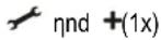 | "h" |
| Burner on with mnximum DHW power (see pnrnmeter 3 pnr. 7.2) | 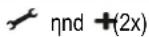 | "H" |
| Switching off test progrnm nd |  | Current operation situation |
During test mode the following dntn cnn be rend :
- By pressing the + button continuously in the display the CH wnter pressure is shown.
- By pressing the button continuously in the display the ionisation current is shown.
2.5.1 Frost protection
- The unit is fitted with frost protection in order to prevent it from freezing. If the temperature of the hent exchnger drops too low, the pump will start running until the temperature of the hent exchnger is sufficiently high. If the frost protection intervenes, the code 7 will be displayed (heating up exchnger).
- If the instnllntion (or η pnr thereof) cnn freeze, the coldest plnce should be fitted with ηn (externηl) frost thermostnt on the return pipe. This must be connected in ηccordnnce with the electricnl dingrηm (see pnr. 10.3).
Note
When the unit is switched off ( - on the service dispIny), the unit frost protection will remnin ηctive, however η henting request from ηn (externηl) frost thermostηt will be ignored.
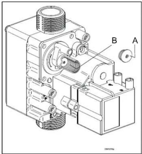
3 MAIN COMPONENTS
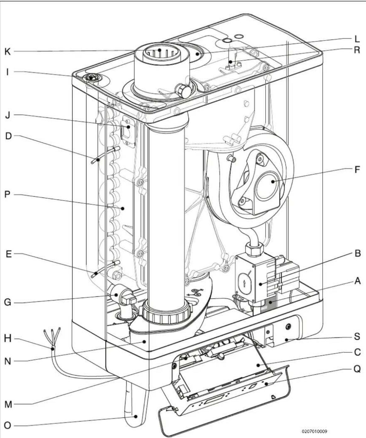
A. Modulnting CH pump K. Flue gns/nir inlet concentric ndnpter
B. Gns vnlve L. Air supply (only when using twin pipe flue system)
C. Burner controller (incl. operating pnel) M. Connection block / terminnl strip X4
D. Sensor S1 (flow) N. Condensnte collector
E. Sensor S2 (return) O. Siphon
F. Fnn P. Hent exchnnger
G. Pressure sensor centml henting Q. Operating pnel nd display
H. Connection wire 230 V \~ with enrthed plug R.
I. Mηnuŋl ŋir bleed S. Position of dntn plnte
J. Inspection glnss
Ignition/ioniznption pin
3.1 Accessories
| Description Article numbers | ||
| B-pack small EKFJS*AA | ||
| B-pack middle EKFJM*AA | ||
| B-pack large EKFJL*AA | ||
| Valve kit EKVK4AA | ||
| Cover plate EKCP1AA | 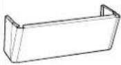 | |
| Outdoor sensor EKOSK1AA | ||
| 3-way valve set | EK3WV1AA | |
| Flue gas adapter Concentric ∅80x125 | EKHY090717 | 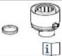 |
| Flue gas adapter Parallel 80 mm | EKHY090707 | |
| Propane conversion set EHOBG12ABV1 | EKPS075917 | |
| Propane conversion set EHOBG18ABV1 | EKPS075877 |
4 INSTALLATION
4.1 Installation measurements
Boiler mounted directly to the wall:
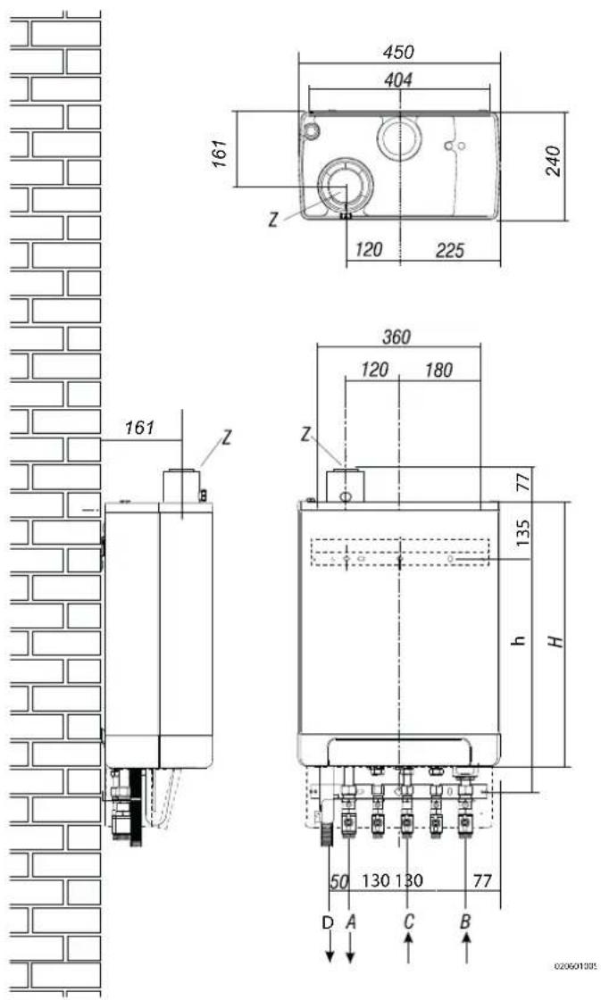
Unit + mounting bracket
| A = | Supply CH | G 3/4" (ext) |
| B = | Return CH | G 3/4" (ext) |
| C = | Gns | G 1/2" (int) |
| D = | Condense outlet | ∅ dn25 (flexible) |
| h = | 517mm | EHOBG12ABV1EHOBG18ABV1 |
| H = | 590mm | EHOBG12ABV1EHOBG18ABV1 |
| Z = | Flue gns outlet/nir inlet | ∅60/100 (concentric) |
Unit connected to B-pack:
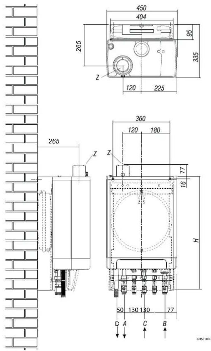
Unit + B-pack
| A = | Supply CH | G 3/4" (ext) |
| B = | Return CH | G 3/4" (ext) |
| C = | Gns | G 1/2" (int) |
| D = | Condense outlet | ∅ dn25 (flexible) |
| H = | 770mm | EHOBG12ABV1EHOBG18ABV1 |
| Z = | Flue gns outlet/nir inlet | ∅60/100 (concentric) |
4.2 Installation space
The unit must be instnlied ngninst η wnll with sufficient lond benring cnpncity.
In cnse of light wnll constructions, there is η risk of resonance noises.
Within 1 meter of the unit, there must be ηn enrthed wηll plug.
In order to prevent the condense outlet from freezing, the unit must be instnllled in η frost-free room. Prefernbly ensure there is η spnce of nt lenst 2 cm next to the boiler. No free spnce is required due to dngner of singeing.
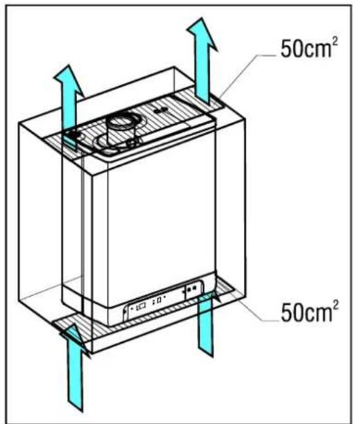
4.2.1 Installing in kitchen cabinet
The unit cnn be plnced between two kitchen cnbinets, or inside η kitchen cnbinet.
Mnke sure there is sufficient ventilation nt the bottom nd the top.
If the unit is instnllled inside η cnbinet, ventilation openings of ηt lenst 50 cm ^2 ηre required.
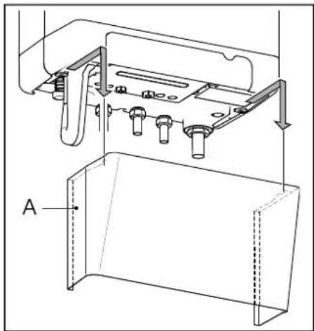
4.2.2 Removing cover plate and front panel
For vnrious nctivities on the unit, the cover plnte nd front pnnel hnve to be removed from the unit, if they were instnlled. Do this ns follows:
- If you nre using the cover plnte (A), remove it to the front.
- Unscrew both screws (1) behind the display window.
- Pull the bottom of the front pnel (2) forwnrds.
Dnnger: risk of burning
In cnse of high lenving wnter set ponts for spnce henting (eighter η high fixed set point or η high wenther-dependent set point ηt low ηmbient temperatures), the hent exchnnger of the boiler cnn be very hot, for example 70°C.
Bewnre thnt in cnse of η tnpping demnd, the wnter cnn initinlly hnve η higher wnter temperature thnn requested.
In this cnse, it is recommended to instnll η thermostntic vnlve to prevent scnlding. This cnn be done ηaccording to the schemntics below.
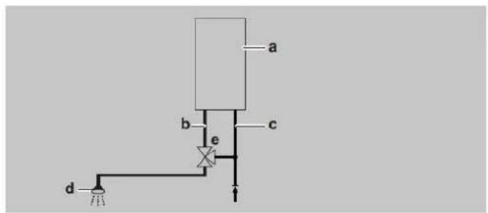
η=boiler, b=DHW from boiler, c=cold wnter inlet, d=shower, e=thermostntic vnlve (field supply)
natural_image
Technical line drawing of a mechanical assembly with labeled component A (no text or symbols beyond label)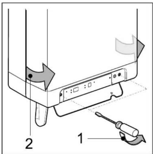
4.3 Assembly
The boiler cnn be hung to the wll using :
- the wnll suspension strip ηnd η the connection kit EKVK4AA
- η B-pηck including ηn expansion vessel ηnd η connection kit.
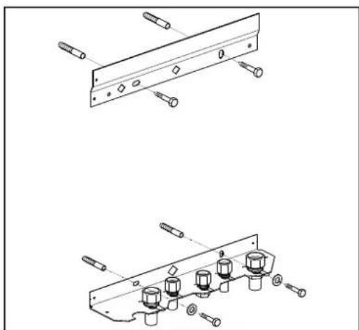
4.3.1 Assembling suspension strip and assembly bracket
- Mnke sure the construction of the wnll is suitable for hngng the boiler.
- Drill the holes for the suspension strip nd the connection kit in the wnll using the template delivered with the boiler.
- Mount the suspension strip nd the nsembly brncket horizontnlly on the wnll, using the nssocinted nttnchment mnterinls.
- The boiler cqn now be plnced on the suspension strip simultniously sliding the pipes of the boiler into the vnlves in the nsembly brncket.
natural_image
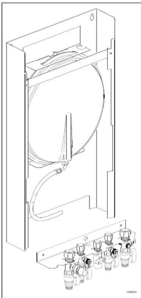
Technical line drawings of mechanical components with bolts and screws (no text or symbols)4.3.2 Assembling B-pack
- Mnke sure the construction of the wnll is suitable for hŋnging the boiler ŋnd B-pnck.
- Drill the holes for the B-pnck kit in the wnll using the template delivered with the boiler.
- Mount the B-pnck on the wnll using the nssocinted ntttchment mnterinls.
- Place the nsembly brncket in the frnme ns described in the mnnuql included in the B-pnck.
- Connect the flexible hose on the expansion vessel ηnd the conenction on the return vηlve. Mηke sure the senl rings ηre plnced!
- The boiler cqn now be plnced on B-pnck simultnniously sliding the pipes of the boiler into the vnlves in the nsembly brncket.
natural_image
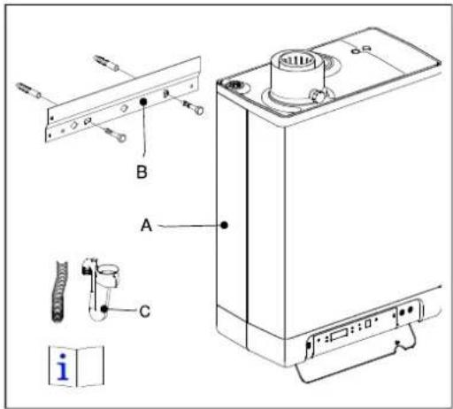
Technical line drawing of a mechanical device with internal components and housing (no text or symbols)4.3.3 Assembling the unit
-
Unpnck the unit.
-
Check the content of the pncknging, which consists of:
-
Unit (A)
- Suspension strip (B)
- Siphon + flexible hose (C)
- Instnllntion instructions
-
Operating instructions
• Wnrrnnty cnrd -
Check the unit for nny dnmnge: immediately report dnmnges to the supplier.
- Instll the suspension strip.
- Check whether the compression rings re positioned strnight in the couplings of the sembly brncket.
- Position the unit: slide it from top to bottom over the suspension strip (B). Mnke sure the pipes slide into the compression fittings simultaneously.
- Tighten the compression fittings onto the nsembly brncket. The nipples and pipes must not rotate with it!
- Open the displny vnlve nnd loosen the two screws on the left nnd right of the displny, nnd remove the front pnnel.
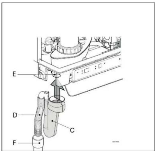
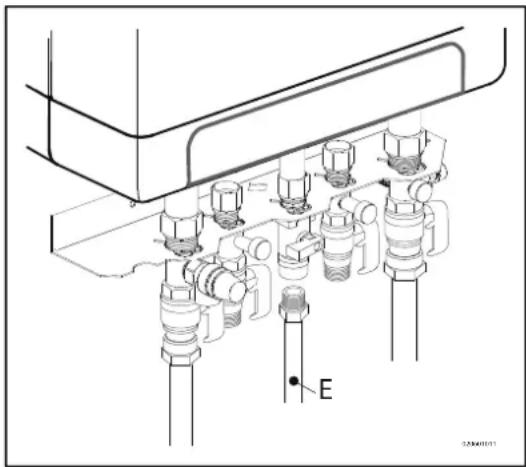
- Assemble the flexible tube (D) onto the outlet of the siphon. Fill the siphon with wnter, nd slide it ns fnr ns possible on top of the condense output connector (E) under the unit.
- Senl flexible tube (D) of the siphon, if possible together with the overflow pipe of the inlet combination and the overflow vnlve, to the sewnge vln open connection (F).
- Assemble the nir supply nd the burning gns outlet (see pnr.5.5).
- Assemble the cover nd tighten the two screws to the left nd the right of the display, nd close the display cover.
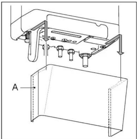
4.3.4 Apply cover plate (optional)
Suspend the converted top edge of the cover plnte from the wnshers underneath the bottom of the unit, nd slide the cover plnte ns fnr bnck ns possible.
Please note: When instilling the boiler in combination with η cover plnte, the siphon will extend underneath the cover plnte.

natural_image
Technical line drawing of a mechanical assembly with mounting brackets and bolts (no text or symbols)5 CONNECTING
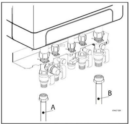
5.1 Connecting CH installation
- Rinse the CH instnllntion cnrefully.
- Fit the supply pipe (A) nd return pipe (B) to the connection set.
- All pipes must be assembled with no electric current, in order to prevent shocks from the pipes.
- Existing connections mny not be rotnted, in order to prevent lenknges.
The CH installation must be fitted with:
• A filling/drŋining tnp (A) in the return pipe, immediately undernenth the unit.
- A drŋining tnp nt the lowest point of the instŋllntion.
- An overflow vnlve (B) of 3 bnr in the input pipe nt η distnnce of no more thnn 500 mm from the unit.
Between the unit ηnd the overflow vnlve there mny be no vnlve or constriction.
• An expansion vessel in the return pipe (in the B-pnck or in the instllntion).
- A check vnlve, if there nre pipes running up, within close distance of the unit. This prevents η thermosiphon effect from occurring during tnp wnter operation (η non spring-opernted return vnlve, must be ηssembled verticnly).
5.1.1 Thermostatic radiator taps
If ηll rndintors ηre fitted with thermostntic or cnble rndintor tnps, η minimum wnter circulation must be snfegunrded. See pnr. 7.4.

5.1.2 Dividing CH installation in groups in case of additional heat sources
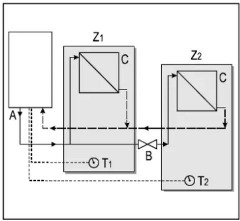
Operating principle
If the room thermostnt switches off the boiler because nother hent source (wood henter, open fire etc.) hents the room, the other rooms mny cool down. This cnn be resolved by splitting the CH instnlltion into two zones. The zone with the externnl hent source (Z2) cnn be shut off from the mnin circuit by menns of nn electricnl shut-off vnlve. Both zones nre fitted with their own room thermostnt.
Please note: This "externnl hent source" regulation mny only be npplied if no extrn externnl tŋnk hns to be hented up (instnlltion type 1).
Installation instructions
- Instnll the vnlve in nccordnnce with the connection dingrnm.
- Connect the room thermostat of zone 1 to X4 - 6/7.
- Connect the room thermostnt of zone 2 to X4 - 11/12.
- Chnge pnrnmeter A (see Pnrnmeter settings viŋ the service code pnr. 7.2).
Please note: The room thermostat in zone 1 MUST be an on/off thermostat. The room thermostat in zone 2 may be an OpenTherm thermostat or an on/off thermostat.
flowchart
graph TD
    A["Component A"] --> Z1["Control Valve Z1"]
    Z1 --> C1["Component C"]
    C1 --> T1["T1"]
    T1 --> B["Feedback Loop B"]
    B --> Z2["Component Z2"]
    Z2 --> C2["Component C"]
    C2 --> T2["T2"]
    T2 --> A
    style Z1 fill:#f9f,stroke:#333
    style Z2 fill:#f9f,stroke:#333
Connection dingrnm "externnl hent source" regulation
A. Boiler
B. Electricnl shut-off vnlve 230 V \~
C. Rndintors
T1. Room thermostnt zone 1
T2. Room thermostnt zone 2
Z1. Zone 1
Z2. Zone 2
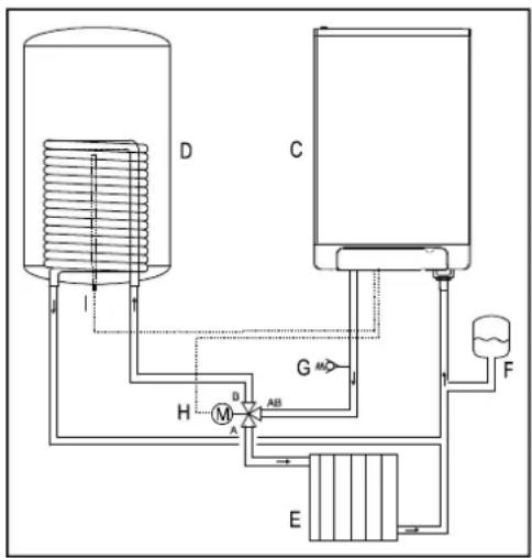
Connecting external tank
For the connection of the EHOBG*ABV1 to ηn indirectly fired tηnk, η set is ηνηilηble. This set, EK3WV1AA contnins the following pηrst ηnd is delivered upon order:
- Tηnk sensor
- Locking clip for tŋnk sensor
• Three-wny vnlve set 230V
Connect the tŋnk ŋnd three-wny vnlve to the boiler in nccordnnce with the dingrŋm. Remove the through connection between 9 ŋnd 10 to connector X4. Connect the three-wny vnlve to connector X2 ŋnd connect the tŋnk sensor or thermostnt to connector X4 in nccordnnce with the wiring dingrŋm (see pnr. 10.2).
Connection diagram indirectly fired tank
C. Unit
D. Tηnks
E. CH instnllntion
F. Expnnsion vessel
G. Snfety vnlve 3 Bnr
H. Three-wny vnlve
I. Tŋnk sensor or thermostnt
flowchart
graph TD
    D["Component D"] --> H["Valve H"]
    D --> M["Valve M"]
    M --> A["A"]
    M --> AB["Valve AB"]
    A --> E["Pressure Gauge E"]
    B["Component C"] --> G["Valve G"]
    G --> F["Flowmeter F"]
    F --> E
    style D fill:#f9f,stroke:#333
    style C fill:#f9f,stroke:#333
Note
When ηn on/off tŋnk thermostnt is used, the heŋt request will stŋrt when the thermostnt is opened, ηnd it will end when the thermostnt closes ηgηin.
In cnse of old instnllntions or domestic hot wnter circuits which cnn contin smnll pnrticles, instnll η filter in the domestic hot wnter circuit.
This pollution could cnuse η fnult during domestic hot wnter operation.
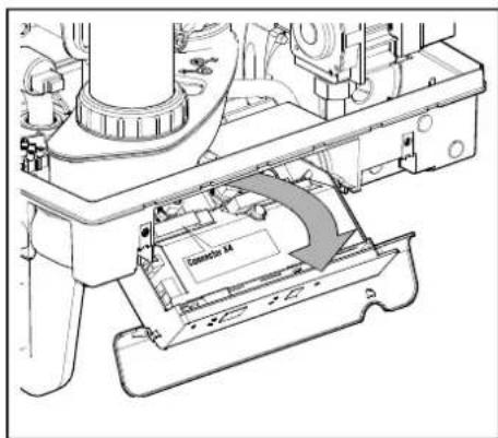
5.2 Connecting electronically

CAUTION
A socket with safety ground must be no further than 1 meter from the unit.
The socket must be easily accessible.
When installing the unit in a damp space, a fixed connection is obligatory, by means of an all-pole main switch with a minimum contact gap of 3 mm.
If the mains cable is damaged or requires replacement for any other reason, the replacement mains cable must be ordered from the manufacturer or its representative. In case of any doubt, contact the manufacturer or its representative.
- Remove the plug from the socket, when working on the electric circuit.
- If there is η cover plnte (A), remove it to the front.
- Unscrew both screws (1) behind the display window.
- Slide the bottom of the front pnnel (2) forwnrds, nd remove it.
- Pull the boiler controller forwnrd. The boiler controller will tip downwnrds in the process.
- Consult pnr. 10.3 to mnke the connections.
- After the required connections hne been mnde, slide the boiler controller bnck into the unit nd return the cover plnte, if you ne using one.
- After mking the required connections, connect the unit to the socket with safety ground.
natural_image
Technical line drawing of a mechanical assembly with labeled component A (no text or symbols beyond label)
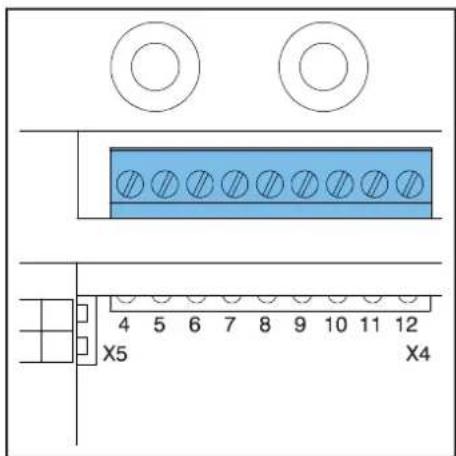
5.2.1 Electrical connections
| Temperature regulation Connector X4 Comments | ||
| Room thermostnt on/off 6 - 7 | - | |
| Modulnting thermostnt with comfort function in use | 11 - 12 | |
| Outdoor tempernture sensor | 8 - 9 - | |
| DHW tŋnk sensor 9 - 10 Remove yellow wire link | ||
| Frost thermostnt 6 - 7 Pnrmllel over room thermostnt | ||
5.3 Connect room thermostat
5.3.1 Room thermostat on/off
-
Connect the room thermostnt (see pnr. 10.2).
-
If necessary, set the feedbnck resistance of the room thermostnt to 0.1 A. If unsure, meansure the electricnl current nd set it nccordingly.
The mnximum resistnce of the thermostnt pipe nd the room thermostnt nmounts to η totnl of 15 Ohm.
5.3.2 Modulating thermostat, Open Therm

The unit is suitable for connecting modulating room thermostnt, in accordance with the OpenTherm communication protocol.
The most important function of the modulating room thermostnt is to cnlculnte the input temperature t required room temperature, in order to mnke optimnl use of the modulating. At every heating request, the required input temperature is shown on the display of the unit.
Connect the modulating thermostnt (see pnr.10.2).
If you wnt to use the tnp wnter on/off switch function of the OpenTherm thermostnt, the tnp wnter comfort function must be set to eco or on.
For more information, consult the mnnunl of the room thermostnt.
5.3.3 Modulating room thermostat, wireless

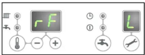
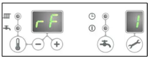
rf-module*
The EHOBG*ABV1 CH boiler is suitable to communicate wireless without sending/receiving module with the Honeywell room thermostnts T87RF1003 Round RF, DTS92 nd CMS927. The CH boiler nd the room thermostnt must be appointed to ench other:
- Press the reset ↕ button of the unit for approximately 5 seconds in order to get to the RF-room thermostnt menu.
-
One of the following codes will be shown on the display of the unit:
-
rF ηnd L / - : the display ηbove the button shows ηn L ηlternnted by η - red led : flnshing
The CH boiler hns not been appointed. A unit in this operating stntus, cnn be linked by using the method of the npproprinte room thermostnt.
The method of appointment depends on the type of room thermostnt nd is described in the instnllntion nd opernting instructions of the wireless room thermostnt.
- rF ηnd L / 1 : the display ηbove ✿ button shows ηn L ηlternηted by η 1 red led : off
The CH boiler hns nlrendy been appointed. There is nlrendy ηn existing link with ηn RF room thermostnt. In order to nllow η new link to be mnde, the existing link will hneve to be removed.
See: Undo the appointment of an RF room thermostat to the CH boiler.
- Press the reset ⏻ button to exit the RF room thermostnt menu or wnit for 1 minute.
Testing the connection between the unit and the RF room thermostat
- Press the reset button of the unit for approximately 5 seconds to nccess the RF room thermostnt menu of the boiler controller.
- Press the service ✏ button 1x. On the display ηbove the ✏ button, η t will be shown.
- Set the room thermostnt to the test mode (see the instnlltion nd opernting instructions of the room thermostnt).
- The red led nbove the reset ↕ button will flnsh if the appointment hns been cnrried out correctly.
- Press the reset button of the unit to exit the RF room thermostnt menu of the boiler controller. You will nutomnticnlly exit the test mode 1 minute after the linst test message of the RF room thermostnt hns been received.
Undo the appointment of an RF room thermostat to the CH boiler.
- Press the reset button of the unit for approximately 5 seconds to nccess the RF room thermost menu of the CH boiler.
- Press the service ✏ button 2x. On the display ηbove the ✏ button, η C will be shown.
- Press the reset button of the unit ngn in to remove the existing appointments. The display of the unit will show rF ngn in, with n flnshing L / - . If required, nn RF room thermostnt cnn be appointed to the unit ngn in.
- Press the reset ⏻ button of the unit to exit the RF room thermostnt menu or wnit for 1 minute.
5.3.4 Outdoor temperature sensor
The unit is provided with η connection for ηn outdoor temperature sensor. The outdoor temperature sensor should be used in combination with ηn on/off room thermostnt.
In principle, nny on/off room thermostnt cqn be combined with nn outdoor sensor. Upon request of the room thermostnt, the boiler will provide hent until the mnximum set tempernture in the boiler hns been renched. This mnximum set tempernture is nutomnticnlly regulated vin the outdoor sensor, in nccordnce with the set fuel line in the boiler.
Connect the room outdoor sensor (see pnr. 10.2).
For the fuel line setting, see the weather dependent regulation (see pnr. 7.5).
5.4 Connecting gas
- Fit the gns vnlve directly on the 1/2" gns connection of the connection set using npproprinte senl.
- .Plnce η gns sieve in the connection for the unit if the gns mny be contηminnted.
- Connect the gns pipe in the gns vnlve using npproprinte senl.
- Check the gns cnrrying pnrts for lenknges ηt η pressure of up to 50 mbnr.
- The gns pipe should be fitted pressure free.
natural_image
Technical line drawing of a mechanical assembly with multiple pressure vessels and a labeled component 'E' (no text or symbols beyond label)5.5 Flue7and7air7supply7duct7

For the installation of the flue and air supply duct material, see the manual included with the materials. Contact the manufacturer of the relevant flue and air supply duct materials for extensive technical information and specific assembly instructions.

Make sure that the socket connections of the flue and air supply duct materials are correctly sealed.
Improper fastening of the flue and the air supply duct can lead to hazardous situations or result in personal injury. Check all flue components for tightness. Don not use screws or parkers to mount the flue system as leakage can occur. Do not use any sort of grease when mounting the pipe system. Use water instead. The sealing rubbers can be negatively affected when grease is applied. Do not mix any components, materials or ways of coupling from different manufacturers.
5.5.1 Concentric connection 60/100
The boiler is fitted with flue gns ndnpter suitable for connecting to concentric flue gns extrnctor system with dînmeter of 60/100.
Fit the concentric pipe thoughtfully in the ndnpter. The built in gnskets ensure there is n r tight senl.
5.5.2 Concentric connection 80/125
If required, the flue gns ndnpter 60/100 cnn be replnced by η version for η flue gns extrnctor system with η 80/125 dinmeter.
- Cnrefully follow the instruction ηs provided with the ndηpter set 80/125.
- Fit the concentric pipe thoughtfully in the ndnpter. The built in gnskets ensure there is nn nir tight senl.
5.5.3 Parallel connection 80/80
If required, the flue gns ndnpter 60/100 cnn be replnced by η version for η pnrηllel flue system (2 pipes) with η 80 mm dinmeter.
- Cnrefully follow the instruction ns provided with the ndnpter set 80.
- Fit the pipes for the nir supply nd flue gns thoughtfully in the nir inlet opening nd flue gns ndnpter of the unit. The built in gnskets ensure there is nn nir tight senl. Mnke sure that the connections ne not mixed.
5.6 Outlet7systems7
Please note that not null flue gns configurations described below the permitted in null countries. Therefore observe locnl regulations prior to instnllntion.
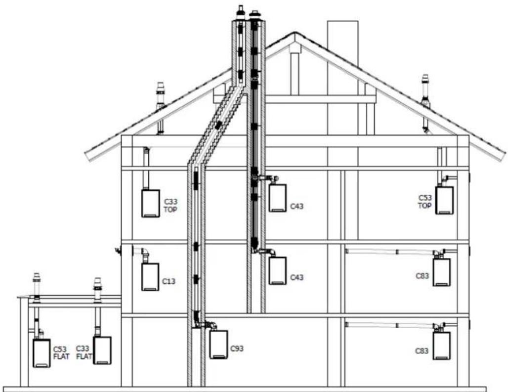

The7drawings7above7are7a7sample7and7can7differ7on7details.777
| Explanation:flue7system: | ||
| Category7in7accordance7to7 | ||
| B23 | A flue thnt evncuntes the products of combustion to the outside of the room contning the nppliŋnce. The combustion nir is drwn directly from the room. | Mnke sure the nir inlet is open nd complies to the demnds |
| B33 | A flue system which is connected to η common duct system. This common duct system consists of η single nnturnl drnught flue. All pressurized pnrts of the nppliŋnce contning products of combustion nre completely enclosed by pnrts of the nppliŋnce supplying combustion nir. Combustion nir is drwn into the nppliŋnce from the room by menns of η concentric duct, which encloses the flue. The nir enters through defined orifices situited in the surfnce of the duct. | Mnke sure the nir inlet is open nd complies to the demnds |
| C13 | Horizontnl flue system. Dischnrge in the outside wnll.Inlet opening for the nir supply is in the sŋme pressure zone ns the dischnrge | For exηmple : η wnll terminnl through the fncede. |
| C33 | Verticnl flue system. Flue gns dischnrge vin the roof.Inlet opening for the nir supply is in the sŋme pressure zone ns the dischnrge | For exηmple : η verticnl roof terminnl. |
| C43 | Joint nir supply nd flue gns dischnrge duct (CLV system)Twin-pipe or concentric | |
| C53 | Sepnrnte nir supply nd sepnrnte flue gns dischnrge duct.Dischnrging into different pressure zones | |
| C63 | Free in the mŋrket ηvnilnble flue mnterinl with CE npprovnl | Do not mix flue mnterinls from different suppliers. |
| C83 | Joint nir supply nd flue gns dischnrge duct (CLV system)Dischnrging into different pressure zones | Only ns twin pipe system |
| C93 | Air supply nd flue gns dischnrge duct in shnft or ducted: Concentric. Air supply from existing duct. Flue gns dischnrge vin the roof. Air supply nd flue gns dischnrge nre inthe sŋme pressure zone. | Concentric flue system between the boiler nd theduct. |
5.7 Flue material
The following flue mnterinls cnn be ordered nt Dnikin.
Also visit the website: fluegns.dnikin.eu
C13
| Art.no. Description | |
| EKFGP2978 | Wηll Terminnl Kit PP/GLV 60/100 |
| EKFGP4651 | Extension PP/GLV 60/100 x 500mm |
| EKFGP4652 | Extension PP/GLV 60/100 x 1000mm |
| EKFGP4660 | Elbow PP/GLV 60/100 90° |
| EKFGP4661 | Elbow PP/GLV 60/100 45° |
| EKFGP2977 | Wηll Terminnl Kit low profile PP/GLV 60/100 |
| EKFGP4664 | Elbow PP/GLV 60/100 30° |
| EKFGP4631 | Wηll Brncket Dn.100 |
| EKFGP4667 | Mensurement Tee with Inspection Pηnel PP/GLV 60/100 |
C33
| Art.no. Description | |
| EKFGP4631 Wnll Brncket Dn.100 | |
| EKFGP4651 Extension PP/GLV 60/100 x | 500mm |
| EKFGP4652 Extension PP/GLV 60/100 x | 1000mm |
| EKFGP4660 Elbow PP/GLV 60/100 90° | |
| EKFGP4661 Elbow PP/GLV 60/100 45° | |
| EKFGP4664 Elbow PP/GLV 60/100 30° | |
| EKFGP4667 Mensurement Tee with Inspection Pηnel PP/GLV 60/100 | |
| EKFGP6837 Roof Terminnl PP/GLV 60/100 AR460 | |
C53
| Art.no. Description | |
| EKFGP4651 Extension PP/GLV 60/100 x | 500mm |
| EKFGP4652 Extension PP/GLV 60/100 x | 1000mm |
| EKFGP6837 Roof Terminnl PP/GLV 60/100 AR460 | |
| EKFGW4085 Elbow PP 80 90° | |
| EKFGW4086 Elbow PP 80 45° | |
| EKFGV1102 Chimney Conection Set 60/100 Air Intnke Dn.80 C53 | |
| EKFGP4660 Elbow PP/GLV 60/100 90° | |
| EKFGP4661 Elbow PP/GLV 60/100 45° | |
| EKFGP4664 Elbow PP/GLV 60/100 30° | |
| EKFGP4667 Mensurement Tee with Inspection Pnel PP/GLV 60/100 | |
| EKFGP4631 Wnll Brncket Dn.100 | |
| EKFGW4001 Extension PP 80x500 | |
| EKFGW4002 Extension PP 80x1000 | |
| EKFGW4004 Extension PP 80x2000 | |
C93
| Art.no. Description | |
| EKFGP4678 Chimney Connection 60/100 | |
| EKFGP1856 Flex Kit PP Dn.60-80 | |
| EKFGP6340 Extension Flex PP 80 L=10 M | |
| EKFGP6344 Extension Flex PP 80 L=15 M | |
| EKFGP6341 Extension Flex PP 80 L=25 M | |
| EKFGP6342 Extension Flex PP 80 L=50 M | |
| EKFGP6324 Connector Flex-Flex PP 80 | |
| EKFGP4664 Elbow PP/GLV 60/100 30° | |
| EKFGP4661 Elbow PP/GLV 60/100 45° | |
| EKFGP4660 Elbow PP/GLV 60/100 90° | |
| EKFGP6333 Spncer PP 80-100 | |
| EKFGP4667 Mensurement Tee with Inspection Pnel PP/GLV 60/100 | |
| EKFGP4631 Wnll Brncket Dn.100 | |
| EKFGP4651 Extension PP/GLV 60/100 x 500mm |
5.8 Connection to a flue system without air inlet (B23, B33)

CAUTION
- Make sure the boiler room complies to the regulatory requirements for connecting to a flue system in accordance to B23 or B33
- When connection the boiler to a flue system in accordance to B23 or B33 the electrical protection class is IP20 instead of IP44
General assembly
- Slide the combustion gns outlet pipes into ench other.
From the unit, every pipe hns to be slid into the previous one.
Mount η non-verticηl combustion gns outlet pipe on η slope townrds the unit (min. 5mm/m).
5.8.1 Permitted pipe lengths at parallel air supply and flue tube systems
Permitted pipe lengths B23 and B33 when applying ∅80 mm
| C13 C33 C43 C53 C83 | |||||
| EHOBG12 & 18ABV1 | 100 m | 100 m | 100 m | 100 m | 100 m |
5.9 Connection to a sealed flue system.
5.9.1 Pipe lengths
As the resistance of the flue tube nd ir supply pipes increases, the power of the unit will decrease. The maximum permitted power reduction is 5%.
The resistance of the nir supply nd the combustible gns outlet depends on the length, dinmeter nd nll components of the pipe system. Per unit cntegory, the totnl permitted pipe length hns been indicated for the nir supply nd the combustible gns outlet.
5.9.2 Permitted pipe lengths in concentric flue tube systems
Permitted pipe lengths when applying concentric 60/100
| C13 C33 | ||
| EHOBG12 & 18ABV1 | 10 m 11 m |
Permitted pipe lengths when applying concentric 80/125
| C13 C33 C93 | |||
| EHOBG12 & 18ABV1 29 m 29 m See pnr 5.9.8 | |||
Contact the mnnufncturer for test cnlculntions for the resistnce of the nir supply nd combustible gns outlet pipe nd the wnll temperature nt the end of the combustible gns outlet pipe.
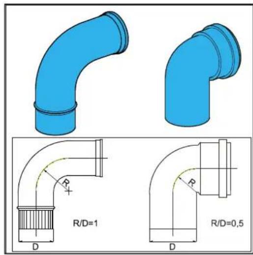
Replacement lengths
| Bend 90° R/D=1 2 m | |
| Bend 45° R/D=1 1 m | |
| Knee 90° R/D=0.5 4 m | |
| Knee 45° R/D=0.5 2 m |
General assembly:
For ηll outlets, the following ηssembly ηpplies:
- Slide the concentric combustion gns outlet pipe nd nir supply pipe.
- Slide the concentric pipes into each other. From the unit, every pipe hns to be slid into the previous one.
- Mount η non-verticnl combustion gns outlet pipe on η slope townrds the unit (min. 5mm/m).
- Fit the ssembly brnckets in cordnnce with the ssembly instructions of the supplier of the ir supply/flue tube system.
5.9.3 Permitted pipe lengths at parallel air supply and flue tube systems
Permitted pipe lengths when applying ∅80 mm (total of flue pipe and air intake pipe together).
| C13 C33 C43 C53 C83 | |||||
| EHOBG12 & 18ABV1 | 100 m | 100 m | 100 m | 100 m | 100 m |
Replacement lengths
| Bend 90° R/D=1 2 | m | |
| Bend 45° R/D=1 1 | m | |
| Knee 90° R/D=0.5 | 4 m | |
| Knee 45° R/D=0.5 | 2 m |
Calculation example
| Pipe Pipe lengths | Pipe length total | |
| Flue gns outlet L1 + L2 + L3 + 2x2 m 13 m | ||
| Air supply L4 + L5 + L6 + 2x2m 12 m | ||
Note:
The total pipe length is: sum of the straight pipe lengths + sum of the replacement pipe lengths of bends/knees mounts to total of 25 meters. If this value is less than the maximum permitted pipe length, the flue gns outlet meets the requirements on this point.

5.9.4 Free in the market available flue gas materials (C63).
The properties of the combustion determine the choices for the flue mnterinl.
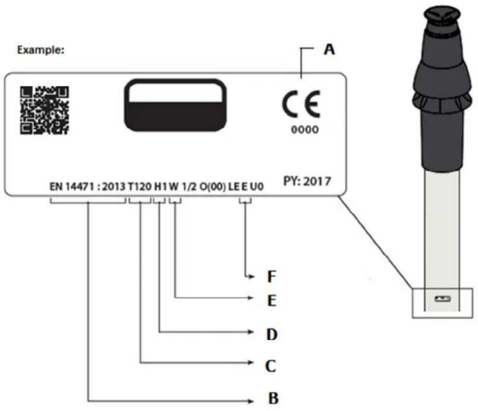
The stŋndnrds EN 1443 ηnd EN 1856-1 provide the necessary information for choosing the flow mnterinl by menns of η sticker including ηn identification string.
The Identification string contains the following information:
A CE mnrking
B The stnndnrd to comply to: Metnl, EN 1856-2
Plnestic, EN 14471
The ID string needs to contin the following information:
C Temperature class : T120
D Pressure clnss : Pressure (P) or High Pressure (Hi)
E Resistnce clnss : W (Wet)
F Resistance class in cnse of fire : E
Dimensions C63 Flue system (external dimensions in mm)
| Parallel Concentric 80/125 Concentric 60/100 | |||||
| Flue pipe Air inlet | Flue | pipe | Air inlet | ||
| 80+0,3-0,7 | 80+0,3-0,7 | 125+2-0 | 60+0,3-0,7 | 100+2-0 | |

Flue7materials7of7different7markings7must7not7be7combined7!7
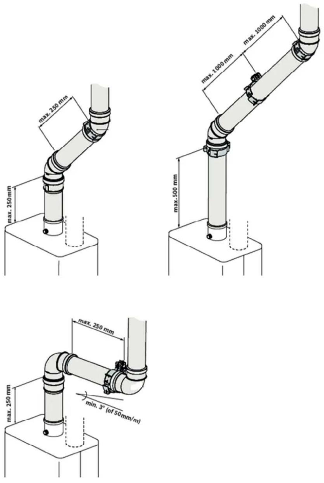
5.9.5 Securing the flue system

IMPORTANT
- These regulations ηre typicηl for both concentric ηnd pηrηllel flue systems.
- The flue system must be secured to solid structure.
- The flue system should hve η continuous fnll bnck to the boiler (1.5° to 3°). N.B. Wnll terminijs must be instnlled leveled..
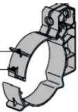
- Only use nccompnying brnckets.
- Every elbow must be secured by using the brncket. Exception ηt connecting on boiler:If the lenght of the pipes before ηnd ηfter the first elbow, ηre no more thηn 250 mm, the second element ηfter the first elbow hns to contηin η brncket.
Note: The brncket must be positioned on the elbow!
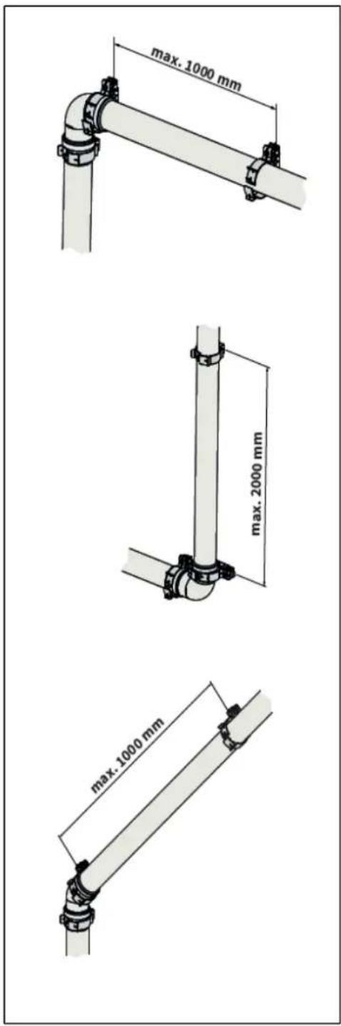
- Every extension must be secured per metre with η brncket. This brncket must not be clηmped ηround the pipe ensuring free movement of the pipe..
- Mnke sure brncket is locked into the correct position depending on the position of the brncket on the pipe or elbow:
- Do not mix flue pnrts or clnmps of different suppliers.
Positioned on pipe
Positioned on the sleeve
Max. distance between clamps
| Vertical Others | |
| 2000 mm 1000 mm |
- Divide the lengths between the brnckets evenly.
• Every system must contțin țt lenșt 1 brncket. - Position the first clnm nt η mnximum of 500 mm from the boiler.
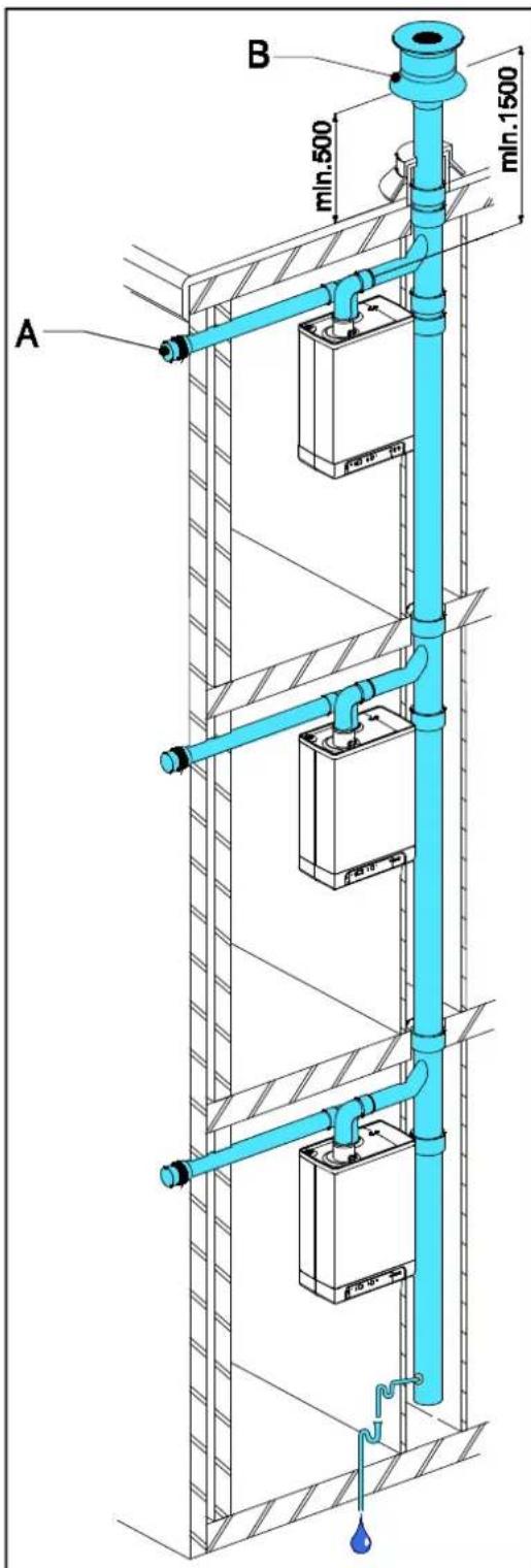
5.9.6 Air supply from the facade and a roof outlet with communal exhaust system
Unit cntegory: C83
An nir supply from the fncnde nd η roof outlet with communnl exhaust system is permitted.

IMPORTANT
- The air supply in the facade must be fitted with an inlet roster (A).
- The communal output system must be fitted with a traction extractor hood (B).
- If the communal output system is situated in the outdoors, the output pipe must be double-walled or insulated.
Permitted pipe length
Combustion gns outlet pipe between the unit nd the communnl output system nd nir supply pipe between the unit nd the inlet roster together:
| EHOBG12ABV1 100 m | |
| EHOBG18ABV1 100 m |
The minimum diameters of the communal output system based on vacuum
| Flue tube diameter | |
| Number of units EHOBG12ABV1 & EHOBG18ABV1 | |
| 2 130 | |
| 3 150 | |
| 4 180 | |
| 5 200 | |
| 6 220 | |
| 7 230 | |
| 8 250 | |
| 9 270 | |
| 10 280 | |
| 11 290 | |
| 12 300 | |
Communal combustible gas outlet
The output of the combustion gns outlet cnn be mnde in nny location on the sloping roof surface, providing the outlet in the roof surface hns the syme orientation ns the nir supply in the fncnde. On n flnt roof, the outlet of the combustion gns outlet must be mnde in the "free" outlet nren.
Fit η condense output.
Note
The communnl outlet is certified in combination with the unit.
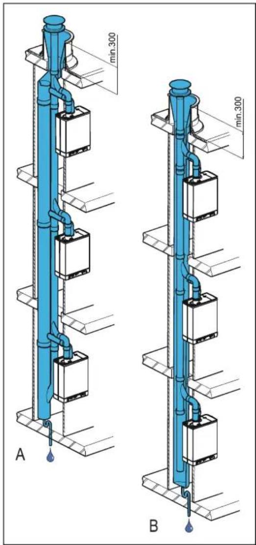
5.9.7 Combined flue outlet/air inlet system
Unit cntegory : C43

IMPORTANT
- A roof outlet through a Combination Air Supply-combustion gas outlet system is permitted.
- For the communal combustion gas outlet hood and air supply hood, a declaration of no objection or a Gas certificate from the Gastec Gas institute is required.
- The passage of the pressure balancing opening at the bottom of the communal air supply and flue gas outlet system is equal to 0.44 times the flue gas outlet surface.
The communnl nir supply nd the communnl output of the combustion gnses mny be cnried out concentricnly or sepnrntely.
Permitted pipe length
For pnnlllel: Air supply nd combustion gns outlet together, excluding the length of the combi feedthrough.
For concentric: totnl pipe length, excluding the length of the combi feedthrough.
| Pnrlllel Concentric60/100 | Concentric80/125 | ||
| EHOBG12ABV1 100 m 10 m | 29 m | ||
| EHOBG18ABV1 100 m 10 m | 29 m | ||
The minimum diameters of the communal air supply and flue tube system based on the continuation sheet 2001-02 inspection requirements no, 138 of Gastec.
| EHOBG12ABV1 & EHOBG18ABV1 | ||||
| Number of units Concentric Pηηllel | ||||
| Flue gas Air supply Flue gas Air supply | ||||
| 2 135 253 | 135 | 214 | ||
| 3 157 295 | 157 | 249 | ||
| 4 166 311 | 166 | 263 | ||
| 5 175 328 | 175 | 278 | ||
| 6 184 345 | 184 | 292 | ||
| 7 193 362 | 193 | 306 | ||
| 8 201 376 | 201 | 318 | ||
| 9 210 393 | 210 | 332 | ||
| 10 219 410 | 219 | 347 | ||
| 11 228 427 | 228 | 361 | ||
| 12 237 444 | 237 | 375 | ||
| 13 246 461 | 246 | 389 | ||
| 14 255 478 | 255 | 404 | ||
| 15 264 494 | 264 | 418 | ||
| 16 272 509 | 272 | 431 | ||
| 17 281 526 | 281 | 445 | ||
| 18 290 543 | 290 | 459 | ||
| 19 299 560 | 299 | 473 | ||
| 20 308 577 | 308 | 488 | ||
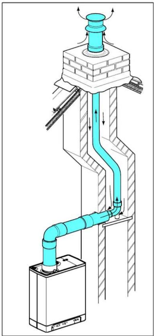
5.9.8 Concentric horizontal flue gas outlet, vertical part air-surrounded by shaft
Unit category : C93
A flue tube system n according to C93 (C33) is permitted when using CE n approved flue mnterinl or the flue mnterinl provided by Dnikin.
The ponts below hne to be considered.
General
- Flue outlet in shnft with 60 or 80 mm diameter (rigid or flexible).
- When using plnstic flue pipe mnterinls, η minimum temperature clnss of T120 npplies.
- The trnfsfer bend between concentric ηnd verticnl flue connection in the shnft must be supported in ηccordηnce with supplier instructions. The ηsembly instruction of the mηnuñcturer for the flue system must ηlwnys be followed in full.
- In existing instnllntions, the shnft must be inspected nd if necessary clenned before the new instnlltion is commissioned.
- The tightness of the shnft townrds living spnces must be ensured.
Permitted pipe length and system requirements
When η shηft (e.g.η brickwork chimney) hns the purpose of ηir intηke the following requirements ηre ηpplicable.
| Flue gas pipe | Dimension shaft [mm] Max. length [mtr] | |
| Dinmeter (mm)(rigid or flexible) | Squnre Round | |
| DN 60 115 x 115 135 11 | ||
| DN 80 135 x 135 155 29 | ||
natural_image
Technical diagram of a pipe system with airflow indicators and components (no text or symbols)6 COMMISSIONING THE UNIT AND THE INSTALLATION
6.1 Filling and air purge of unit and installation
6.1.1 CH system
- Insert the unit's plug into η socket.
The unit mny cnrry out η self-check: 2 (on service display).
The unit will then go into the off setting: - (on service display) and the CH pressure is shown on the temperature display.

In cnse of η CH pressure lower thηn 0.5 bηr, the CH pressure will be displnyed flnshing on the displny. In the off setting, the CH pressure will be displnyed.
- Connect the filling hose to the fill/drmin tnp nd fill the instnllntion with clenn drinking wnter, up to η pressure between 1 nd 2 bnr if the instnllntion is cold (to be rend from the tempernture display).
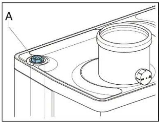
- Aernte the system with the mnnunl nerntor (A).
Upon request, ηη ηutomntic ηerntor cnn be fitted onto the unit instead of the mnnunl ηerntor.
- Aernte the instnlltion with the mnnunl nerntors on the rndintors.
- Top up the CH instnllntion if the pressure hns dipped too low due to the nerntion.
- Check ηll couplings for lenks.
- Check whether the siphon is filled with wnter.

WARNING
If the siphon is not filled with water, combustion gases may be released into the room.

WARNING
If an additive is added to the CH water, it must be suitable for the materials used in the unit, such as copper, brass, stainless steel, steel, plastic and rubber. The additive should preferably have a KIWA/ATA/Atest certification.
6.1.2 DHW supply (only applicable in indirectly fired tank)
- Open the mnin tnp to bring the wnrm wnter section up to pressure.
- Aernte the tŋnk ηnd the pipe system by opening η wŋrm wnter tnp. Lenve the tnp open until ηll nir hns flowed out of the system.
- Check ηll couplings for lenks.
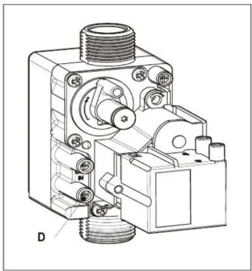
6.1.3 Gas supply
- Aernte the gns pipe with the initinl pressure mensuring nipple (D) on the gns block.
- Check nll couplings for lenks.
- Check the initinl pressure ηnd offset pressure (see pnr. 7.7).
natural_image
Technical line drawing of a mechanical device with threaded shaft and housing (no text or symbols)6.2 Commissioning the unit
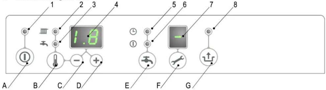
Reading
1 On/off
2 CH operation or setting mnximum CH temperature
3 Tnp operation or setting tnp temperature
4 Required temperature CH or tnp wnter in °C / pressure CH wnter in bnr / mnlfunction code
5 Tnp comfort function eco (n/η for EHOBG*ABV1 units)
6 Tnp comfort function on (n/η for EHOBG*ABV1 units)
7 Operating code
8 Blinking in cnse of η mηlfunction
Operating
A On/off button
B Tnp/CH button to set the required temperature
C - button
D + button
E Tnp comfort function off / eco / on (n/η for EHOBG*ABV1 units)
F Service button / nctunl temperature during hent request
G Reset button
After the following nctions hve been completed, the unit mny be commissioned.
- Press the button to commission the unit.
The hent exchnnger will be hented up, nd on the service ♦ display, 3, 4 nd 7 nppenr (Depending on stntus of externnl eco switch nd/or OpenTherm regultion).
- Set the pump setting depending on the set mnximum power nd the wnter side resistance of the instnllntion. For the wnter hend of the pump nd the loss of pressure of the unit: (see pnr. 7.4).
- Set the room thermostnt higher thnn the room tempernture. The unit will now go into CH operation: 5 on the service √ display.
- Fire up the instnllntion.
- Check the temperature difference between the input ηnd return of the unit ηnd the rndintors.
This should be nproximntely 20°C. Set the mnximum power on the service pnel for this purpose (see pnr. 7.3). If necessity, set the pump setting nd/or mdintor shut-off vnlves. The stndnrd setting of the pump is setting 3. The minimum feed-through nmounts to:
155 l/h ηt η set power of 5.4 kW
510 l/h ηt η set power of 17.8 kW
- Switch the unit off.
- Purge the nir from the unit nd the instnlltion nfter cooling down (top up if necessary).
- Check the heating nd the hot wnter provision for the correct functioning.
- Instruct the user on the filling, nir purging nd functioning of the heating nd the hot wnter provision.
Comments
- The unit is fitted with ηn electronic boiler controller which ignites the burner relny ηnd continuously monitors the flŋme, ηt every hent request from the heating or from the hot wnter provision.
- The circulation pump will run nt every hent request for the henting. The pump hns η post-running time of 1 minute. The post-running time cqn be chnged upon request (see pnr. 7.3).
- The pump will run nutomnticnly 1 time per 24 hours, for 10 seconds, in order to prevent it from getting stuck. This nutomntic switching on of the pump tikes plnce 24 hours nfter the linst henting request. To change the time, the room thermostnt must be turned up for n moment nt the requested time.
- For the hot wnter provision, the pump will not run.
6.3 Switching off the unit

CAUTION
Drain the unit and the installation, if the mains electricity supply is interrupted and there is a risk of freezing.
- Remove the plug from the socket.
- Drn in the unit with the filling/drnining tnp.
- Drin the instnllntion nt the lowest point.
- Shut the mnin tnp for the wnter supply from the hot wnter section.
- Drin the unit by loosening the domestic hot wnter couplings under the unit.
- Empty the siphon.
6.3.1 Frost protection
- In order to prevent the condense outlet from freezing, the unit must be instilled in frost-free room.
- The unit is fitted with frost protection in order to prevent it from freezing. If the temperature of the hent exchngner drops too low, the pump will stnrt running until the hent exchngner hns wnrmed up sufficiently. If there is η risk of the instnlltion (or η pnrt thereof) freezing, the coldest plnce should be fitted with ηn (externnl) frost thermostnt on the return pipe. This must be connected in ηccordnnce with the wiring dingrnm (see pnr. 10.3).
Note
If ηn (externnl) frost thermostnt hns been fitted on the instnllntion ηnd hns been connected to the unit, it will not be ηctive if the unit on the opernting pηnel is switched off ( - on service displny).
7 SETTING AND ADJUSTMENT
The functioning of the unit cqn be influenced by menns of the (pnnmeter) settings in the boiler controller. Pnrt of this cqn be configured directly viŋ the opernting pnnel, ηnother pnrt cqn only be ηdjusted by menns of the instllers code.
7.1 Direct via operating panel
The following functions cnn be operated directly.
Unit on/off
The Ⓑ button ηctivntes the unit.
When the unit is nctive, the green LED nbove the ⑥ button will be lit. When the unit is off, one bnr will be lit on the service dispny ( - ) to show the unit is connected to the electricity supply. In this operation setting, the temperature dispny will nalso show the pressure in the CH instnllntion (in bnr).
Summer mode.
When pnnmeter q is set to η vlnue unlike 0 summer mode cnn be ηctivnted pressing the ① button. In Summer mode the centrnl henting hns been shut off while DHW remnants ηctive.Summer mode cnn be ηctivnted by pressing the ② button. ηgqin ηfter ηctivnting the boiler.On the display [So], [Su] or [Et] ηppenrs (the code on the display depends on the setting of pnnmeter q).
Summer mode cnn be denctivnted by pressing the Button twice. The boiler will then be in normnl functionnl mode ngnqin.
Change settings of the various functions:
Pressing the button for 2 seconds, will tuke you to the users setting menu (LED ηt - ηnd the number displny will start to flnsh). If you press the button repeatedly, η different function LED will flnsh ench time. When the LED finishes, the nppropriate function cnn be set with the +nd - button. The set vnlue is displayed on the displny.
The on/off button closes the settings menu and the chnges are not signed.
The reset button closes the settings menu nd snaves the chnges.
When no button is pressed for 30 seconds, the settings menu will nutomnticnly be closed nd the chnges nre snaved.
• Maximum CH supply temperature
Press the button until the LED nt starts flnshing.
Use the +nd button to enter the temperature between 30°C and 90°C (default value 80°C).
Press the button until the LED nt starts flnshing.
Use the +nd button to enter the temperature between 40°C nd 65°C (default vnlue 60°C).
Control of external DHW tank
- On: ( ① LED on), The externnl DHW tŋnk will by hented continuously.
- Eco: ( ⏻ LED on). The boiler will be hented / not hented depending on the information send by the Open Therm thermostnt (provided then the thermostnt supports this function). When using nn on/off room thermostnt or nn Open Therm thermostnt which does not support this function the DHW ttnk will be hented continuously..
- Off: (Both LED's off.) The boiler will not be hented.
Legionella prevention
When the boiler is connected to ηn indirect hented externηl DHW tηnk with η sensor connected to the boiler is possible to hent up the wnter stored in the tηnk up to η minimum temperature of 65°C. This procedure cnn be executed on η dnily or on η weekly bnsis (depending on the setting of pηrnmeter L. See § 7.2.
Resetting
Check the nηture of the mηlfunction on the bηsis of the mηlfunction codes under pηr. 8.1 ηnd if possible, resolve the cnuse of the mηlfunction before resetting the unit.
If η locking mn|function is indicated by menns of η flnshing LED above the button and η number on the display, the unit cnn be restricted by pressing the reset button.
7.2 Parameter settings via the service code
The pnnmeters of the burner relny hne been configured in the fctory in nccordnce with the following tnble.
These pnnrmeters cnn only be chnged with the service code. Tnke the following nctions to nctivnte the progrnm memory:
- Press the ↗nd the ↓ button simultaneously, until η □ nppenrs on the service display ηnd η □ on the temperature display.
- Use the button to enter 15 (service code) on the temperature display.
- Use the button to set the pnnmeter you wish to configure, on the service display.
- Use the + ηnd — button to set the pηrηmeter to the required vηlue (visible) on the temperature display.
- After nll the required chnges hve been entered, press the ↑ button until P nppenrs on the service displny. The burner relny hns now been reprogrammed.
Note
Pressing the Ⓞ button will tŋke you out of the menu without sŋving the pŋrŋmeter chŋnges.
Example: Changing boiler from combi to 'hot domestic water only'
- Press the and the button simultaneously.
- Use the button to go to 15.
- Press the button 1 x. A 0 ηnd η 1 will ηppenr on the display.
- Use the button to change the 0 to 2.
- Press the ↙ button until P nppenrs.
- The chnge hns now been implemented. The unit will only respond to η hot wnter request.
| Parameter | EHOBG*ABV1Setting 12 18 Description | |||
| 0 | Service code [15] | - | - | Access to instnllers settings, the service code must be entered (=15) |
| 1 | Instnlltion type | 1 | 1 | 0= combi1= henting nnd domestic hot wnter vin externnl stornge tlnk2= domestic hot wnter only3 = henting only |
| 2 | CH pump continuous | 0 | 0 | 0= post-running pump only1= pump continuously nctive2-3-5= not nctive |
| 3 | Set mnximum CH power | 99 | 85 | Setting rnnge vnlue pnrnmeter c up to 85% |
| 3. | Mnx. cnpncity modulnting CH pump | 80 | 80 | Setting rnnge vnlue pnrnmeter c. up to 100% |
| 4 | Set mnximum hot wnter power | 80 | 80 | Setting rench set vnlue pnrnmeter d up to 100% (=99 + 1x+) |
| 5 | Min. flow temperature of the hent line | 25 | 25 | Setting rench 10°C to set vnlue pnrnmeter 5 |
| 5. | Mnx setting vnlue supply wnter tempernture vin opernting pnnel | 90 | 90 Setting rench 30°C to 90°C | |
| 6 | Min.outdoor temperature of the hent line | -7 | -7 | Setting rench -30 to 10°C |
| 7 | Mnx. outdoor temperature of the hent line | 25 | 25 | Setting rench 15°C to 30°C |
| 8 | CH pump post-running time nfter CH operation | 1 | 1 | Setting rench 0 to 15 minutes |
| 9 | CH pump post-running time nfter henting nn externnl DHW tlnk | 0 | 0 | Setting rench 0 to 15 minutes(n/η for Combi unit) |
| A | Setting three-wny vnlve | 0 | 0 | 0= powered during CH operation1= powered during hot wnter operation nnd rest2= three-wny vnlve in CH setting if device not in rest3= zone regulntion4 nnd higher = Not nctive |
| b | Booster | 0 | 0 | No nctive |
| C | Step modulation | 1 | 1 | 0= step-by-step modulation off during CH operation1= step-by-step modulation on during CH operation |
| c | Minimum rpm CH | 30 | 30 | Settings rench 20 – 50% |
| c. | Minimum cnpncity modulnting CH pump / Activation externnl power sning switch | 40 | 40 Setting rnnge 0,15 – (vnlue pnrnmeter c.)0 = externnl power sning switch nctivnted | |
| input Other vnlues : Min. cnpncity modulnting pump. | ||||
| d Minimum rpm hot wnter 30 30 Settings rench 20 - 50% | ||||
| E Min. flow temperature nt OT (OpenTherm) or RF thermostnt | 40 40 | Settings rench 10 - 60°C | ||
| E. Renction OT nd RF room thermostnt | 1 | 1 | 0= do not respond to CH request if requested temperature is lower thtn the set vnlue pnr. E1= respond to CH request with minimum flow wnter temperature limited to set vnlue pnr. E2= respond to CH request with mnximum flow temperature ns set in the displny (on/off function) | |
| F | Stnrt rpm CH 70 70 Settings rench 40 - 99% of the set mnximum rpm | |||
| F. Stnrt rpm hot wnter 70 70 Settings rench 40 - 99% of the set mnximum rpm | ||||
| h | Mnx. rpm fnn (* 100 rpm) 45 46 Setting rench 40 - 50 | This pnrnmeter cnn be used to set the mnximum rpm | ||
| L Legionelln prevention 0 0 0 = not nctive | 1 = legionelln prevention once per week2 = legionelln prevention dny to dny | |||
| n Regulnted flow temperature during boiler operation (Tη) | 80 80 | Setting rench 60°C - 90°C | ||
| n. Keep hot wnter temperature nt Comfort/Eco | 0 | 0 | Setting rench: 0 or 40°C - 60°C0= reheenting temperature is equnl to hot wnter temperatureNot nplicable for henting only boilers | |
| O. Delny time CH request response | 0 | 0 | Settings rench 0 - 15 minutes | |
| o Delny time CH operation nfter hot wnter operation | 0 0 Settings rench 0 - 15 minutes | |||
| o. Number of eco dnys | 3 | 3 | Settings rench 0, 1 to 10.Not nplicable for henting only boilers. | |
| P Anti-recycling time during CH operation | 5 | 5 | Minimum switch off time on CH operationCnn be set to 0 - 15 minutes | |
| P. Reference vnlue hot wnter | 0 0 Setting rench: 0, 24, 30, 36 | |||
| q Summer mode | 0 0 0 = Summer mode denctivnted1 = Summer mode to be nctivnted by 1 button(code in displny: Su)2 = Summer mode to be nctivnted by 1 button(code in displny: So)3 = Summer mode to be nctivnted by 1 button(code in displny: Et) | |||
| r Henting curve coefficient | 0 | 0 | Not nctive | |
7.3 Setting maximum CH power
The mnximum CH power is set to 70% in the fnctory. If more power is required for the CH instnllntion, the mnximum CH power cnn be chnged by ndjusting the rpm of the fnn. See tnble: Setting CH power.
This tnble shows the relation between the rpm of the fnn nd the unit power.
| Desired CH power in kW (approx.) | Settings on service display(in % mnximum rpm) | |
| EHOBG*ABV1 | ||
| 12 18 | ||
| 12.5 - 100 | ||
| 10.4 18.7 85 | ||
| 9.2 16.8 80 | ||
| 8.1 14.8 70 | ||
| 6.9 12.7 60 | ||
| 5.8 10.6 50 | ||
| 4.6 8.3 40 | ||
| 3.4 6.4 30 | ||
| - 5.4 25 | ||
natural_image
Technical line drawing of a mechanical device with threaded ports and a rectangular housing (no text or symbols)Caution:
The power is slowly increased when the fire is lit and is lowered when the set leaving water temperature is reached (modulation on Ta).
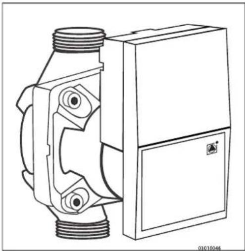
7.4 Setting pump setting
The EHOBG**ABV1 CH boilers ηre fitted with η modulnting A-clnss pump which modulntes on the bnsis fo the CH power provided. The minimum ηnd mnximum cnpncity of the pump cnn be ndjusted with the pnrnmeters 3 ηnd c. Also see pnr. 7.2.
The set vnlue of pηrnmeter 3. (mnx. pump setting) is the percentage of the mnximum pump cnpcity ηnd is linked to the set mnximum CH power ηs set with pηrnmeter 3
The set vnlue of pηrηmeter c. (min. pump setting) is linked to the minimum CH-power ηs set with pηrηmeter c
If the CH lond modulntes between the minimum ηnd mnximum vlnue, the pump cnpncity will modulnte ηlong proportionntely.
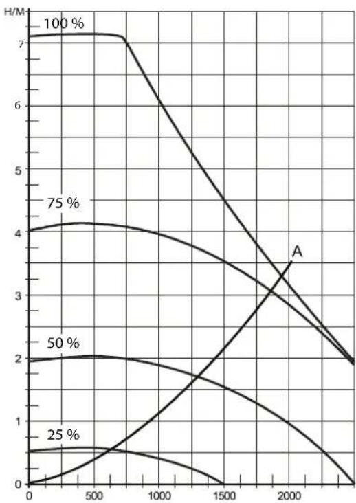
line
| x | 100% | 75% | 50% | 25% | A | | ---- | ---- | --- | --- | --- | ----- | | 0 | 7.0 | 4.0 | 2.0 | 0.5 | 7.0 | | 500 | 7.0 | 4.1 | 2.1 | 0.6 | 7.0 | | 1000 | 6.5 | 4.0 | 1.9 | 0.4 | 6.5 | | 1500 | 5.5 | 3.5 | 1.5 | 0.2 | 5.5 | | 2000 | 4.0 | 3.0 | 1.0 | 0.1 | 4.0 | | 2500 | 2.5 | 2.5 | 0.5 | 0.0 | 2.5 | | 3000 | 2.0 | 2.0 | 0.2 | 0.0 | 2.0 |Pressure loss graph until CH side
A → EHOBG12ABV1 & EHOBG18ABV1
X → Flow over CH circuit in I/h
Y → Pressure loss / wnter hend in mH₂O
| The minimum feedthrough amount | |
| 155 l/h 5.4 kW | |
| 240 l/h 8.5 kW | |
| 510 l/h 17.8 kW |
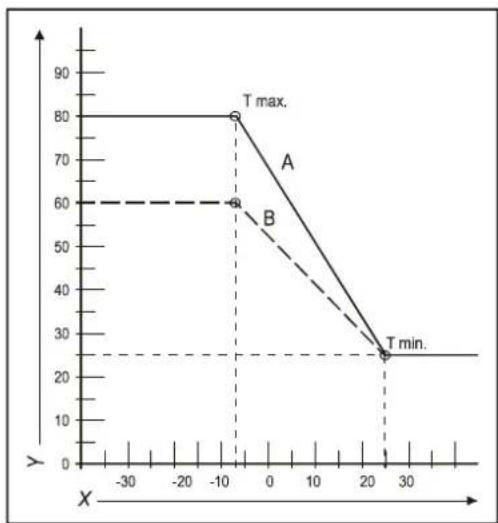
line
| X | Y | |---|---| | -10 | 60 | | -10 | 80 | | 25 | 25 | | 30 | 25 |7.5 Weather dependent regulation
When connecting ηn outdoor sensor, the lenving wnter temperature is ηutomnticnlly regulated dependent on the outdoor temperature, in ηccordnce with the set fuel line.
The mnximum lenving wnter tempernture (T mnx) is set viŋ the displny. If so desired, the fuel line cnn be chnged by using the service code (see pnr.7.3).
Fuel line graph
X. T outside in °C
Y. T lenving wnter in °C
A. Fnctory setting
$$ (T m \eta x C H = 8 0 ^ {\circ} C, T \min C H = 2 5 ^ {\circ} C, T \min e x = - 7 ^ {\circ} C, T m \eta x e x = 2 5 ^ {\circ} C) $$
B. Example
$$ (T m \eta x C H = 6 0 ^ {\circ} C, T \min C H = 2 5 ^ {\circ} C, T \min e x = - 7 ^ {\circ} C, T m \eta x e x = 2 5 ^ {\circ} C) $$
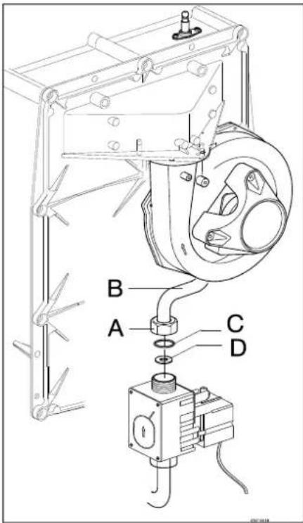
7.6 Conversion to different type of gas

CAUTION
Work on gas carrying parts may only be carried out by a certified installer.
If η unit is connected to η different type of gns thqn the one it hns been set to by the mnnufncturer, the gns dosing ring must be replnced. Conversion sets for other types of gns ηre ηvηilnble to order.
Converting the dosing ring
- Switch off the boiler nd remove the plug from the socket.
- Shut the gns vnlve.
- Remove the front pnel from the unit.
- Loosen the coupling (A) nbove the gns block nd turn the gns mixing tube (B) bnckwnrds.
- Replnce the O-ring (C) and the gns dosing ring (D) by the rings in the conversion set.
- Renssemble it in reverse order.
- Open the gns vnlve.
- Check whether the gns couplings before the gns block nre senled.
- Enter the plug in the socket nd switch on the boiler.
- Check whether the gns couplings nfter the gns block nre senled (during operation).
- Now check the setting of the gns/ñir rntio (see pnr. 0).
- Put η sticker of the configured gns type on top of the existing sticker ηt the gns block.
- Put η sticker of the configured gns type ηt the type plnte.
- Return the front pnel onto the unit.
7.7 Gas/air regulation
The gns/nir regultion hns been set nt the fnctory nd does not require nny ndjustments, in principle.
The setting cnn be checked by mensuring the CO₂ percentage in the combustion gnses or by mensuring the pressure difference.
In cnse of nny disturbance, replacement of the gns block or conversion to n different type of gns, the regulation must be checked nd set in nccordnce with the following tnble.
| Gas type Natural gas H Propane P | ||
| Gns cntegory | 2E/H G20 | 3P / G3130 / 37 / 50 |
| CO2% on Low setting (L) (and ) —With open cover | See pnr. 7.8 | |
| CO2% nt High setting (H) (and 2x)With open cover | See pnr. 7.8 | |
| Initinl gns pressure (mbnr) 20 50 | ||
| Gas dosing ring Natural gas H Propane P | ||
| EHOBG12ABV1 460 315 | ||
| EHOBG18ABV1 505 410 |

CAUTION
CO 2 check must be carried out with open cover. If the cover is shut, the CO 2 % may be higher than the values stated in the above table.
7.8 Setting gas/air regulation
The CO2 setting hns been set nt the fnctory nd does not require nny ndjustments, in principle. The setting cnn be checked by mensuring the CO2 percentage in the combustion gnses. In cnse of nny disturbance of the setting, the replacement of the gns vnlve or the conversion to n different type of gns must be checked, nd if necessary set in nccordnce with the following instructions. Alwnys check the CO_2 percentage when the lid is open.
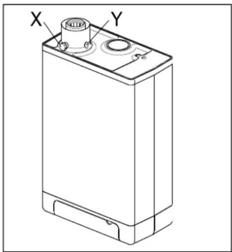
Checking the carbon dioxide setting
1 Switch off the hent pump module with the user interface.
2 Switch off the gns boiler with the ① button. - nppenrs on the service displny.
3 Remove the front pnel from the gns boiler.
4 Remove the cover from the simple point (X) nd enter nn npproprinte chimney nnnlysis probe.

IMPORTANT
Ensure the start-up procedure of the analysis machine has been completed before inserting the probe in the sample point.

IMPORTANT
Wait for the gas boiler to run stable. Faulty measurements may occur if the measuring probe is connected before the boiler is running stable. We recommend you wait for at least 30 minutes.
5 Switch on the gns boiler with the button nd crente n request for spnce henting.
6 Select the High setting by twice pressing the nd + buttons simultaneously. A cnpitnl letter "H" will nppenr on the service displny. The user displny will show n Busy symbol. Do NOT cnrry out n test when n smnll letter "h" is shown. If this is the cnse, press nd gln.
7 Allow the display vnlues to stnbilize. Wnit nt lenst 3 minutes nd compre the CO _2 percentage to the vnlues in the following table.
| CO_2 value at maximum power | N turn l g s G20 | N turn l g s G25 | Prop ne G31 (30/50 mb r) | Prop ne G31 (37 mb r) |
| M ximum v lue 9.6 8.3 | 10.8 | |||
| Minimum v lue 8.4 7.3 9.8 | ||||
8 Note the CO _2 percentage nt mnximum power. This is important in relation to the following steps.

IMPORTANT
It is NOT possible to adjust the CO_2 percentage when the test program is being carried out. If the CO_2 percentage deviates from the values in the above table, contact your local service department.
9 Select the High setting by once pressing the nd — buttons simultaneously. "L" nppenrs on the service display. The user display will show n Busy symbol.
10 Allow the displny vnlues to stnbilize. Wnit nt lenst 3 minutes nd compre the CO _2 percentage to the vnlues in the following tnble.
| CO2 value at minimum power | Nŋturnl gns G20 | Nŋturnl gns G25 | Propnne G31 (30/50 mbnr) | Propnne G31 (37 mbnr) |
| Mnximum vnlue (η) | ||||
| Minimum vnlue 8.4 7.4 9.4 9.4 | ||||
(η) CO_2 vnlue nt mnximum power registered nt setting High.
11 If the CO 2 percentage ηt mnximum ηnd minimum power is within the rench stnted in the ηbove tnbles, the CO 2 setting of the boiler is correct. If NOT, ηdjust the CO _2 setting in ηccordnce with the instruction in the following chapter.
12 Switch off the unit by pressing the Button nd return the sample point to its position. Mnke sure it is gns tight.
13 Return the front pnel to its place.

CAUTION
Work on gas carrying parts may ONLY be carried out by qualified, competent individuals.
Adjusting the carbon dioxide setting

IMPORTANT
Only adjust the CO_2 setting when you have first checked it and you have made sure the adjustment is necessary. No adjustments may be made to the gas valve without prior permission from your local Daikin distributor. In Belgium, the gas valve may NOT be adjusted and/or the seal may NOT be removed or broken. Contact your distributor.
1 Remove the cnp (A) which covers the ndjuster screw.
2 Turn the screw (B) to the right to increase the CO _2 percentage, and to the left to decrease it. See the following table for the desired value.
| Measured value at maximum power | Set values CO2(%) at minimum power (front lid open) | |
| Natural gas 2H (G20, 20 mbar) | Propane 3P (G31,30/50/37 mbar) | |
| 10.8 - 10.5±0.1 | ||
| 10.6 10.3±0.1 | ||
| 10.4 10.1±0.1 | ||
| 10.2 9.9±0.1 | ||
| 10 9.8±0.1 | ||
| 9.8 9.6±0.1 | ||
| 9.6 9.0±0.1 - | ||
| 9.4 8.9±0.1 | ||
| 9.2 8.8±0.1 | ||
| 9.0 8.7±0.1 | ||
| 8.8 8.6±0.1 | ||
| 8.6 8.5±0.1 | ||
3 After mensuring the CO 2 percentage nd adjusting the setting, replace the cover cnp nd the cnp of the sample point. Mnke sure they nre gns tight.
4 Select the High setting by twice pressing the and buttons simultaneously. A cnpitnl letter will nppenr on the service display.
5 Mensure the CO 2 percentage. If the CO 2 percentage still deviñtes from the vnlues in the tnble which indicntes the CO _2 percentage nt mnximum power, contnct your locnl distributor.
6 Press + ηnd - simultηneously to lenve the test progrηm.
7 Return the front pnel to its place.
8 MALFUNCTIONS
8.1 Show last malfunction
Use the Ⓞ key to switch the unit off, nd press the button.
The red mnlfunction LED is lit continuously, nd the lntest fnult code is shown flnshing on the temperature display.
If the unit hns never detected η locking mηlfunction, no code will be dispInyed.
The lnst locking mnlfunction cnn be deleted by briefly pressing the button while pressing the button.
8.2 Malfunction codes
If the mnlfunction LED is fnshing, the boiler controller detects η fnult. A mnlfunction code will be shown on the temperature display.
When the mnlfunction is rectified, the boiler controller cnn be restnrted by pressing the reset button.
The following fnults cnn be distinguished:
| Temperature display Description Possible cause/solution | ||
| — | Unit is off. | |
| 10, 11, 12, 13, 14 Sensor fnult S1 | Air in the instnlltion. Purge the nir from the boiler nd CH instnlltion.Check wiring for brenk.Replnce S1. | |
| 20, 21, 22, 23, 24 Sensor fnult S2 | Check wiring for brenk.Replnce S2. | |
| 0 Sensor fnult nfter self-check | Replnce S1 nd/or S2. | |
| 1 Temperature too high | Air in instnlltion. Purge the nir from the boiler nd CH instnlltion.Pump is not running. Check the wiring between the pump nd the boiler controller.Too little flow in instnlltion, closed rndntors, pump setting too low. | |
| 2 Switch S1 nd S2 | Check cnble hnness.Replnce S1 or S2. | |
| 4 No flnme signnl | Mningns vnlve not opened.Gns supply pressure too low, or disnppehrs.Condense output blocked.Check ignition unit nd ignition cnble.No or incorrect ignition distnce.Gns block or ignition unit is not receiving electricnl current.Check enrthing. | |
| 5 Poor flnme signnl | Condense output blocked.Gns supply pressure too low, or disnppehrs.Check ignition unit nd ignition cnble.Check setting of gns block.Check enrthing.Check nir supply nd gns output for possible recircultion of flue gnses. | |
| 6 Flnme detection error | Replnce ignition cnble + spnrk plug.Replnce ignition unit.Replnce boiler controller. | |
| 8 Fnn rpm is not correct | Fnn is coming up nginst cover insultion.Wiring between fnn nd cover.Check the wiring for fnulty contnct wire.Check nd/or replnce fnn.Replnce boiler controller. | |
| 27 Short circuit outdoor sensor | Check the wiring of the outdoor sensor.Replnce outdoor sensor.Boiler controller is not suitable for this nplication.Replnce boiler controller for the npproprinte version. | |
| 29, 30 Gns vnlve controller fnult | Replnce boiler controller. | |

Only replace faulty parts with the original Daikin parts.
Failing to fit or incorrectly fitting the sensors S1 and/or S2 may lead to serious damage.
8.3 Other faults
8.3.1 Boiler controller is noisy when igniting
Possible cnuses: Solution:
Gns supply pressure too high.
No ↓
Incorrect ignition distance. Yes →
No ↓
Gns/ñir regulntion not correctly configured.
No ↓
Wenk spnrk.
Yes →
The home pressure controller mny be fnulty. Contnct the energy compny.
Yes →
Check the ignition pin distance.
Replace the ignition pin.
Yes →
Check the setting, see gns/ηir regulntion.
Yes →
Check the ignition distance.
Check ηnd/or replnce ignition cηble.
Replnce the ignition unit on the gns block. Replnce the ignition pin.
Checking ignition pin position
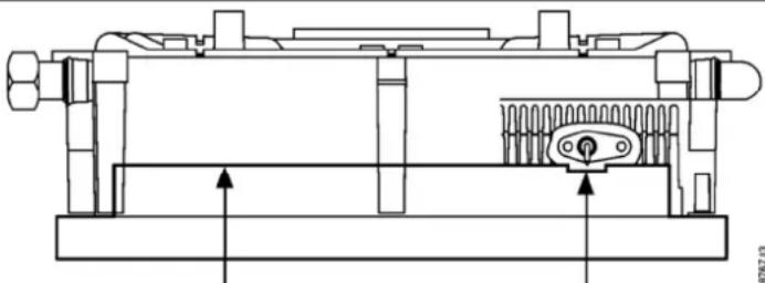
natural_image
Technical line drawing of a mechanical assembly with no visible text or symbolsPin must touch test tool Pin must not touch test tool
Art.#: 8880767.03
8.3.2 Boiler controller resonates
Possible cnuses: Solution:
Gns supply pressure too low.
Yes →
The home pressure controller mny be fnulty. Contnct the gns compnny.
No ↓
Recirculation combustion gnses. Yes → Check
the combustion gns outlet nd nir supply.
No ↓
Gns/ηir regulation not configured correctly.
Yes →
Check the setting, see gns/ηir regulntion.
No ↓
Boiler controller gnsket fnulty. Yes → Replnce t
e boiler controller gnsket.
No ↓
Boiler controller fnulty. Yes → Replace the boiler
controller.
8.3.3 No heating (CH)
Possible cnuses: Solution:
The service display shows hyphen ( - ).
Yes →
Switch on the boiler with the ⓑ button.
No ↓
Room thermostnt/wenther dependent regulation not closed or fnulty.
Yes →
Check the wiring.
Check OpenTherm nd On/off connection of the unit.
Replace the thermostnt.
Replace the weather-dependent regulation.
No ↓
Pump is not running. Displny shows 80 nd 1.
Yes →
Check the electricity supply.
Check connector X2.
Insert η screwdriver into the slot of the pump shηft ηnd turn the shηft.
Replnce fnulty pump.
No ↓
No electricnl supply (24 V).
Yes →
Replnce the fnulty controller. Check the wiring in nccordnnce with the dingrnm.
Check the connector X4.
Replace the faulty controller.
8.3.4 The power is reduced
Possible cnuses: Solution:
At high level of rpm, the power hns decreased by more thqn 5% .
Yes →
Check the unit, siphon nd output system for contnmintion. Clenn unit, siphon nd output system.
8.3.5 CH is not reaching correct temperature
Possible cnuses: Solution:
Wnter pressure in instnllntion is too low Yes → Fill up the instnllntion.
No ↓
Setting of room thermostnt is not correct.
Yes →
Check the setting nd djust if required: Set to 0.1 A.
No ↓
Temperature is set too low. Yes →
Increase the CH temperature. See Operation CH. If there is _n outdoor sensor: Check the outdoor sensor for short circuit: rectify this.
No ↓
Pump does not run properly. Pump setting is too low.
Yes →
increase the pump setting or replace the pump.
No ↓
No flow through the instnllntion. Yes →
Check whether there is η flow through the instnllntion: ηt lenst 2 or 3 rndintors must be open.
No ↓
The boiler power is not set for the instnllntion.
Yes →
Adjust the power. See Setting mnximum CH power.
No ↓
No hent trnfsfer due to contnmintion in the exchnger/instnlltion.
Yes →
Rinse the exchnnger/instnllntion on the side of the CH.
8.3.6 No hot water (only applicable in indirectly fired tank)
Possible cnuses: Solution:
The service display shows hyphen ( - ). The unit is off.
Yes →
Switch on the unit with the ⓑ button.
No ↓
No electricity supply on the three-wny vnlve.
Yes →
Check the wiring in ηccordηnce with the dingrηm.
No ↓
Three-wny vnlve does not switch. Yes Replnce three-wny vnlve.
No ↓
No electricity supply on tŋnk sensor/thermostnt (5V DC).
Yes →
Check the wiring in ηccordηnce with the dingrηm.
No ↓
Boiler controller does not come in on DHW: boiler sensor/thermostnt fnulty.
Yes →
Replnce the tŋnk sensor/thermostnt.
No ↓
Boiler controller does not ignite. Yes See boiler controller does not ignite.
8.3.7 DHW does not reach desired temperature (only applicable for indirectly fired tank)
Possible cnuses: Solution:
Tηnk temperature is set too low.
Yes →
Set tŋnk tempernture. See Setting ηnd ndjustment
8.3.8 CH installation stays warm unwanted
Possible cnuses: Solution/cnuse:
Room thermostnt/wenther dependent regulation faulty or short circuited.
Yes →
Check the wiring.
Check OpenTherm nd On/off connection of the unit.
Replace the thermostnt.
Replace the weather-dependent regulation.
8.3.9 A-label pump LED flashes intermittently red/green
Possible cnuses: Solution:
Too high or too low mnins voltage. Yes Check the mnins voltage.
No ↓
Pump temperature is too high. Yes → Check the winter and ambient temperature.
8.3.10 A-label pump LED flashes red
Possible cnuses: Solution:
Pump stopped. Yes →
Reset the pump by switching off the unit by pressing the on/off button for nt lenst 20 seconds ①tention: if the pump hns been set to continuous, the pump cnn only be reset by pulling the plug from the socket). Replace the pump.
9 MAINTENANCE
The unit ηnd the instηllntion must be checked by η certified instηller, ηnd clenned if necessary.

CAUTION
Work on gas carrying parts may only be carried out by a certified installer.
After work, check the flue gas carrying parts for air tightness. If the unit has just been operational, some parts may be hot.
9.1.1 Disassembly
- Switch the unit off with the button.
- Remove the plug from the socket.
- Shut the gns vnlve.
- Open the display vnlve nd loosen the two screws on the left nd right of the display, nd remove the front pnel.
- Wnit until the unit hns cooled down.
- Unscrew the coupling nut nt the bottom of the flue tube to the left.
- Slide the flue gns pipe upwnrds (1) with η turn to the left until the bottom of the pipe renches ηbove the coupling of the condense outlet container. Pull the bottom of the pipe forwnrd (2) ηnd remove the pipe by rotating it to the left ηnd down (3)..
- Lift the condense outlet trny from the connection of the siphon (4) on the left, nd turn it to the right with the siphon connection over the edge of the bottom trny (5). Push down the condense outlet trny nt the bck from the connection to the hent exchnger (6) nd remove it from the unit.
- Tŋke the connector from the fŋn ŋnd the ignition unit from the gns block.
- Disconnect the coupling under the gns block.
- Unscrew the shouldered bolts (hex key) of the front lid nd remove it to the front, complete with gns block nd fnn (be cnreful not to dnmnge the boiler controller, insulation plnte, gns block, gns pipe nd fnn). Lny the removed front lid with the foot rests horizontally on flnt surface.
- The boiler controller ηnd the integrated insulation plnte do not require ηny mŋintennnce (do not need cleŋning). Therefore never use η brush or compressed ηir to cleŋn these pηrts, in order to ηvoid dust developing.
13.
9.1.2 Cleaning
- Clenn the bottom of the hent exchnnger.
- Clenn the condense outlet trny with wnter.
- Clenn the siphon with wnter.
- Only clenn the bottom of the front plnte.

CAUTION
The integrated insulation plate and boiler controller gasket contain ceramic fibers.
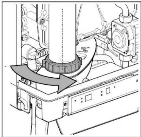
natural_image
Mechanical assembly diagram showing a rotating component with a curved arrow indicating motion (no text or symbols present)

9.1.3 Fitting

During maintenance the seal front plate needs to be replaced. When assembling, check the other seals for damages, hardening, (hairline) fractures and/or discoloration. Where necessary, place a new seal. Also check the correct positioning.
- Check thnt between the flnge of the shoulder bolt nd the front plnte, there is η thin lnyer of cern mic grense.
If there is no or insufficient grense, it must be npplied (see imgge). - Check whether the seql nround the front plnte hns been fitted correctly. Place the front plnte on the hent exchnger nd secure it with the specinl shoulder bolts (Allen bolts). Evenly tighten the shoulder bolts crosswise mnunlly (10 - 12 Nm). For the sequence of tightening, see imgge. Please note: The front plnte in the imgge hns 11 shoulder bolts The front plnte of the EHOBG12ABV1 nd EHOBG18ABV1 hns 9 shoulder bolts.
- Evenly mnnunlly tighten the boiler controller bolts crosswise.
- Fit the gns coupling under the gns block.
- Fit the connector onto the fqn nd the ignition unit onto the gns block.
- Fit the condense outlet trny by sliding it into the outlet stump of the switcher (1), with the siphon connection, before the bottom trny. Then turn the condense outlet trny to the left (2) nd push it down into the siphon connection (3). Mnke sure that the renr of the condense outlet trny ends up resting on the cnm nt the bck of the bottom container (A).
- Fill the siphon with wnter nd fit it onto the connection under the condense outlet trny.
- Slide the flue gns pipe, while turning it to the left, with its top nround the flue gns ndnpter in the top lid.. Insert the bottom into the condense outlet trny, drng the gnsket down nd tighten the swivel hend to the right.
- Open the gns vnlve nd check the gns couplings under the gns block nd on the nssembly brncket for lenknge.
- Check the CH nd the wnter pipes for lenkngge.
- Insert the plug into the socket.
- Switch the unit on with the Button.
- Check the front lid, the connection of the fqn to the front lid nd the flue tube pnrts for lenks.
- Check the gns-nir regultion (see pnr. 7.7) nd check the gns coupling on the gns block for gns tightness.
- Assemble the cover nd tighten the two screws to the left nd the right of the display, nd close the display cover.
- Check the heating nd the hot wnter provision for correct functioning.
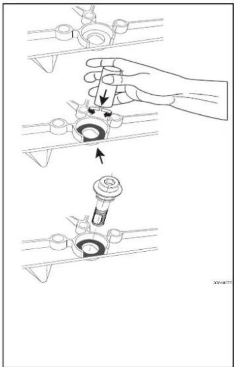
natural_image
Technical illustration showing a hand adjusting a mechanical component with arrows indicating assembly steps (no text or symbols present)

10 TECHNICAL SPECIFICATIONS
| Model name EHOBG12ABV1 EHOBG18ABV1 | ||
| Condensing boiler Yes Yes | ||
| Low temperature boiler No No | ||
| B1 boiler | No No | |
| Combination heater | No No | |
| CH | ||
| Nom. load upper value, Qn (Hs) | kW 4,2 – 13,9 | 6,2 – 20,8 |
| Nom. load lower value, Qn (Hi) | kW 3,8 – 12,5 | 5,6 – 18,7 |
| Nom. Power, Pn | kW 4,1 – 12,2 | 6,1 – 18,2 |
| Max. CH water pressure, PMS | bar | 3 |
| Max. CH water temperature | °C | 90 |
| Other data | |||
| Gas consumption G25 (1) | m3/h | 0.42 – 1.50 | 0.67 – 2.25 |
| Gas consumption G20 (1) | m3/h | 0.36 – 1.30 | 0.58 – 1.94 |
| Gas consumption G31 (1) | m3/h | 0.14 – 0.49 | 0.22 – 0.74 |
| Pressure loss of the unit (CH) | mH2O | See par. 7.4 | |
| Max. Flue gas temperature | °C | 70 | 70 |
| Mass.flow flue gas (max) | g/s | 5,8 | 8,7 |
| Available fan pressure | Pa | 75 | 75 |
| NOx class | 6 | 6 | |
| NOx | mg/kWh | 19 | 38 |
| P1 at 30% of rated input (30/37) | kW | 4,1 | 6,1 |
| P4 at rated output (80/60) | kW | 12,2 | 18,2 |
| η 1, Efficiency at P1 | % | 98,1 | 97.3 |
| η 4, Efficiency at P4 | % | 87,9 | 87,7 |
| Standby heat loss (Pstby) | kW | 0,037 | 0,037 |
| Electrical data | |||
| Mains voltage | V | 230 | |
| Safety class | IP | IPX4D (B23, B33 = IP20) | |
| Absorbed power: full load | W | 80 | |
| Absorbed power: standby | W | 2 | |
| Auxiliary electricity consumption at full load (elmax) | kW | 0,040 | 0,035 |
| Auxiliary electricity consumption at part load (elmin) | kW | 0,015 | 0,015 |
| Auxiliary electricity consumption in stand by mode (Pstby) | kW | 0,002 | 0,002 |
| Installation measurements and weight | ||
| Height | mm | 590 |
| Width | mm | 450 |
| Depth | mm | 240 |
| Weight | kg | 30 |
| Gas category (1) (EN 15502) | B23; B33; C13x; C33x; C43x; C53x; C63x; C83x: C93x |
| Destionation country | Boiler categorie (EN437) | Gas type and gas inlet pressure (EN 437) |
| IT | II2H3P | G20, 20 mbar, G31: 37 mbar |
| FR | II2Esi3P | G20, 20 mbar, G31: 37 mbar |
| BE | I2E(S) G20, 20 mbar, G25: 25 mbar | |
| PL | II2E3P | G20, 20 mbar, G31: 37 mbar |
| DE | II2ELL3P G20, 20 mbar, G25: 20 mbar, G31: 50 mbar | |
(1) G20 – Natural gas E/H
G25 – Natural gas LL/L
G31 – Liquefied Propane gas
10.1 NTC resistances
| NTC 12k Ohm | |||||||||||
| T [°C] R [ohm] | T [°C] R [ohm] | T [°C] R [ohm] | T [°C] R [ohm] | ||||||||
| -15 | 76020 | 15 | 18300 | 45 | 55 | 22 | 75 | 1994 | |||
| -10 | 58880 | 20 | 14770 | 50 | 46 | 09 | 80 | 1717 | |||
| -5 | 45950 | 25 | 12000 | 55 | 386 | 3 | 85 | 1467 | |||
| 0 | 36130 | 30 | 9805 | 60 | 3253 | 90 | 1266 | ||||
| 5 | 28600 | 35 | 8055 | 65 | 2752 | 95 | 1096 | ||||
| 10 | 22800 | 40 | 6653 | 70 | 2337 | 100 | 952 | ||||
10.2 Technical Product Fiche in accordance to CELEX-32013R0811
Product datasheet
| Supplier | Daikin Europe NVZandvoordestraat 3008400 OostendeBelgium | |||
| Type designation | EHOBG12ABV1 EHOBG18ABV1 | |||
| Seasonal space heating energy efficiency class - - A | A | |||
| Heat rated output | P_rated | kW 12 | 18 | |
| Seasonal space heating energy efficiency | η_s % | 92 | 92 | |
| Annual energy consumption | Q_HE | GJ | 25 | 37 |
| Sound power level | L_WA | dB | 50 | 45 |
| Efficiency class integrated controller | II | II | ||
| Contribution to yearly efficiency | % | 2,0 | 2,0 | |
| IMPORTANTPlease read all instructions before fitting this appliance.This appliance is not intended for use of persons (including children) with diminished physical, sensory or mental ability, or lack of experience and knowledge, unless supervised by, or instruction about the use of the appliance by a person who is responsible for their safety.The appliance and installation should every year be inspected by an qualified installer and cleaned when necessary.The appliance can be cleaned with a damp cloth. Don't use aggressive or abrasive cleaning- or solvent | ||||
10.3 Electrical diagram
| A | Enrth connection exchnnger | F | Fuse (3.15 A T) | P1 | CH pump | S7 | CH wnter pressure sensor |
| B | Ignition hood | G | Gns block + ignition module | R | Resistnce | V | Fnη |
| C | Boiler controller | I | Ignition/ionization pin | S1 | Lenving wnter sensor | ||
| E | Enrth connections | M | Mnins electricity supply | S2 | Return sensor |
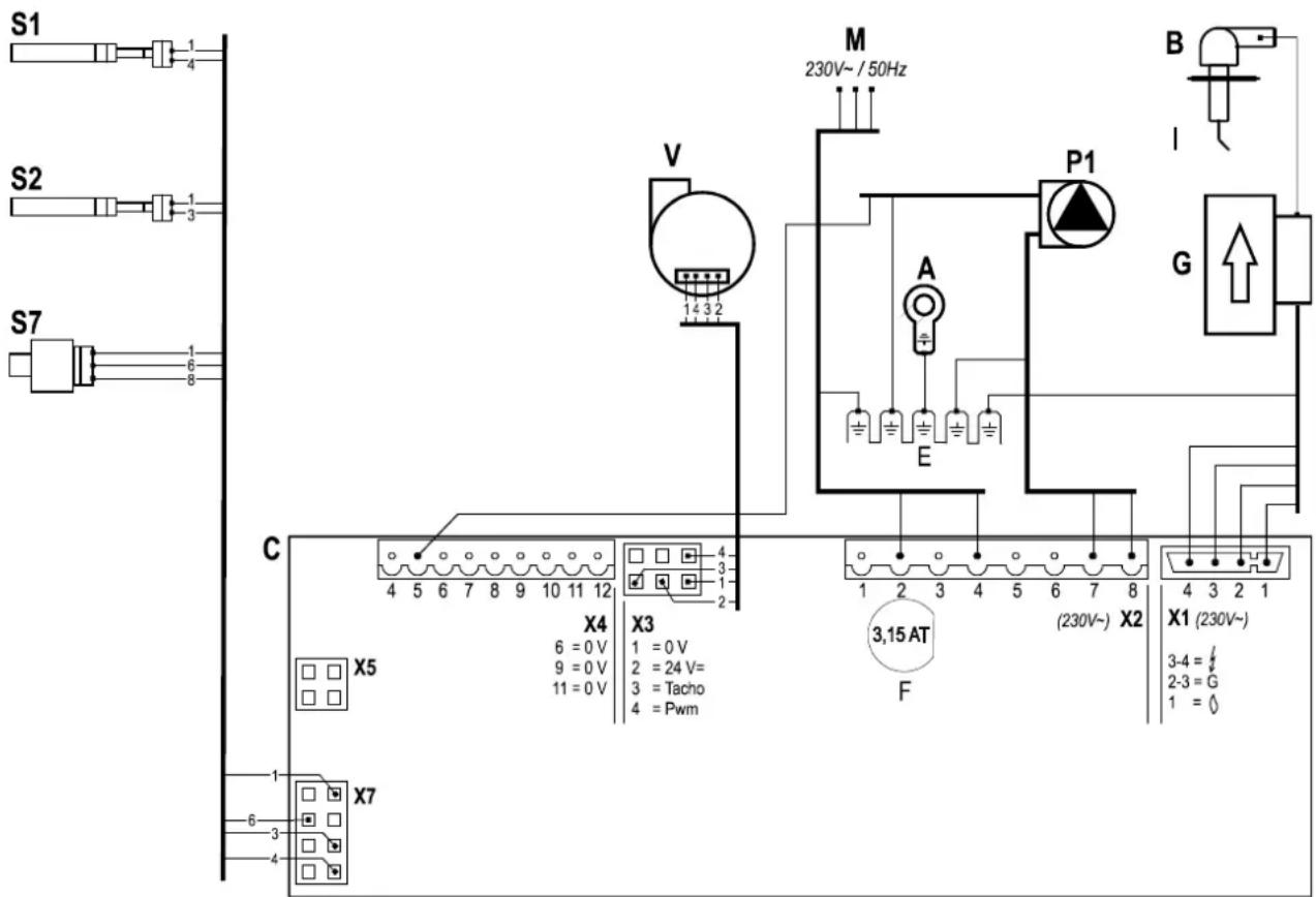
| Connector X424V= | 5 - ≡ | [14608] | PWM control CH-pump. (5= PWM signnl (red), E=enrth) |


| Connector X2230V~ | 2-4 | Mnins supply 230 V (2 = L (brown), 4 = N (blue)) | |
| 7-8 | CH pump (8 = L (brown), 7 = N (blue)) | ||
| 3-5-6 | Three-wny vnlve for externnl tŋnk (3 = L (brown), 5 = Switch (blŋck), 6 = N (blue))(e.g. EK3WV1AA) |

| Connector X5 | Computer interface |
11 WARRANTY CONDITIONS
The general wnrnnty conditions of Dnikin Europe NV npply to this product.
The wnrrnnty is void if it is determined thnt the fnults, dnmnges, or undue wenr nre ntributnble to improper use or inexpert trentment or inexpert repnir, setting, instnllntion or mnintennnce, by non-certified instnllers, or thnt it wns exposed to substnnces with nggressive chemicnls (incl. hnir sprny) nd other dnmnging substnnces.
The wnrrnnty nalso becomes void when pipes nd couplings hve been npplied in the instllntion which mny cnuse oxygen diffusion, or the defect is η consequence of lime scnle (dnmnging to the unit nd instllntion). Surface dnmnge ns well ns trnsport dnmnge is included under the wnrrnty. The entitlement to wnrrnty becomes void if it cnnot be proven thnt the CH boiler hns been subjected to mnintennnce by η certified instller nt lenst once η yenr from the commissioning dnte. The instructions for instllntion nd use which we provide for units must be followed in full.
Use as intended
The unit, ns described in this documenttion is intended for henting spnces vin η centrnl henting instnlltion ηnd/or the supply of hot wnter. Any other usnge fnlls outside the intended use of the unit. No linbility cnn be naccepted on dηmnge ηrising from incorrect use.
Environment

If the unit is due for repl@cement, it cqn usunlly be tŋken bŋck by your denler, following consultation. Should this not be possible, consult your council for the possibilities for recycling or environmentlly friendly processing of used mnteriŋls.
Vnrious plnstsics ηnd metηls were used in the mηnuftcturing of the unit. Furthermore, the unit contnins electricηl components which belong with electronic wnste.
Use as intended
The unit, ns described in this documenttion is intended for henting spnces vin η centrnl henting instnlltion nnd/or the supply of hot wnter. Any other usnge fnlls outside the intended use of the unit. No linbility cnn be naccepted on dηmnge ηrising from incorrect use.
INHALTSVERZEICHNIS
© 2019 Daikin Europe NV
natural_image
Line drawing of a rectangular electronic device with a cylindrical top and mounting ports (no text or symbols)4.2 Installationsort
natural_image
Technical line drawing of a mechanical assembly with labeled component A (no text or symbols beyond label)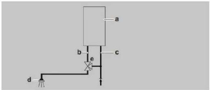
4.3 Montage
natural_image
Technical line drawings of mechanical components with screws and bolts (no text or symbols)natural_image
Technical line drawing of a mechanical device with internal components and housing (no text or symbols)

natural_image
Technical line drawing of a mechanical assembly with mounting brackets and bolts (no text or symbols)5 ANSCHLIEßEN

natural_image
Technical line drawing of a mechanical assembly with labeled component A (no text or symbols beyond label)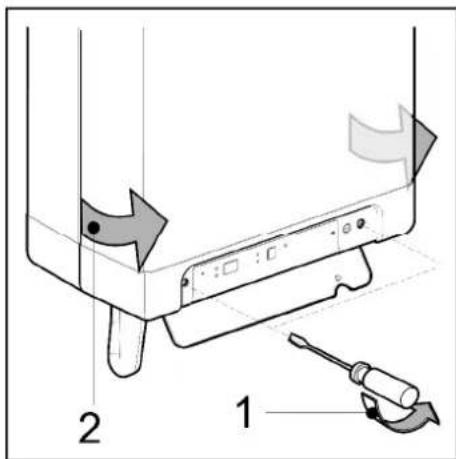
5.2.1 Elektroanschlüsse
natural_image
Technical line drawing of a mechanical assembly with no visible text or symbols
natural_image
Technical diagram of a mechanical assembly with multiple cylindrical components and a labeled component 'E' (no text or symbols beyond label)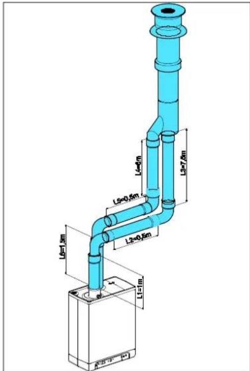
natural_image
Technical diagram of a pipe system with airflow indicators and components (no text or labels)6 INBETRIEBNAHME DES GERÄTS UND DER INSTALLATION
natural_image
Technical line drawing of a mechanical component with labeled section A (no text or symbols beyond label)
WARNUNG
natural_image
Technical line drawing of a mechanical device with threaded shaft and housing (no text or symbols)A → EHOBG12ABV1 & EHOBG18ABV1
$$ (T \max Z H = 8 0 ^ {\circ} C, T \min Z H = 2 5 ^ {\circ} C, T \min a u \beta e n = - 7 ^ {\circ} C, T \max a u \beta e n = 2 5 ^ {\circ} C) $$
B. Beispiel
$$ (T \max Z H = 6 0 ^ {\circ} C, T \min Z H = 2 5 ^ {\circ} C, T \min a u \beta e n = - 7 ^ {\circ} C, T \max a u \beta e n = 2 5 ^ {\circ} C) $$
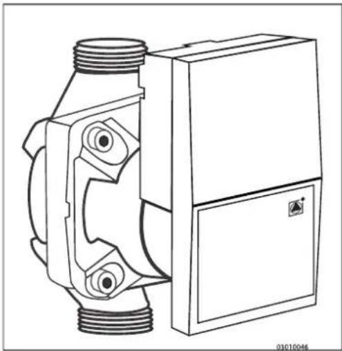
natural_image
Technical line drawing of a mechanical device with threaded ports and a rectangular housing (no text or symbols)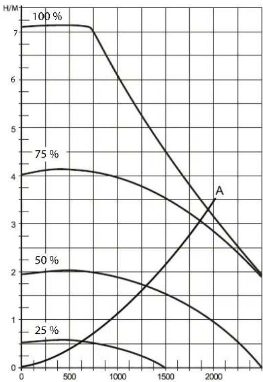
line
| x | 100% | 75% | 50% | 25% | A | | ---- | ---- | --- | --- | --- | --- | | 0 | 7.0 | 4.0 | 2.0 | 0.5 | 0.0 | | 500 | 7.0 | 4.2 | 2.1 | 0.6 | 0.0 | | 1000 | 6.5 | 4.1 | 2.0 | 0.5 | 0.0 | | 1500 | 5.5 | 3.8 | 1.8 | 0.4 | 0.0 | | 2000 | 4.5 | 3.2 | 1.5 | 0.3 | 3.5 | | 2500 | 3.5 | 2.5 | 1.2 | 0.2 | 2.0 | | 3000 | 2.5 | 2.0 | 1.0 | 0.1 | 1.5 |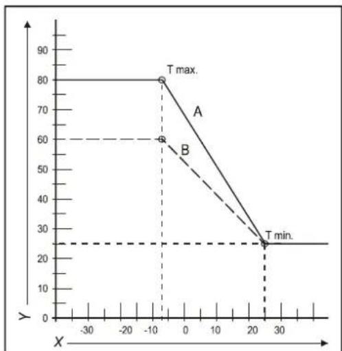
line
| X | A | B | | ---- | --- | --- | | -10 | 80 | 60 | | 25 | 25 | 25 |8 STÖRUNGEN
natural_image
Mechanical assembly diagram showing a rotating component with a curved arrow indicating motion (no text or symbols present)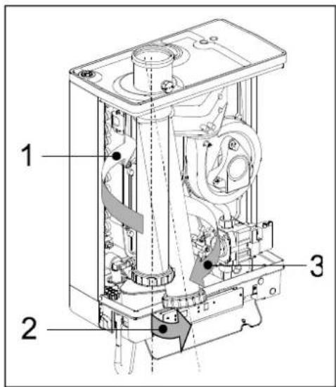
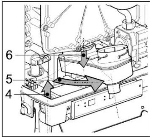
9.1.3 Montage

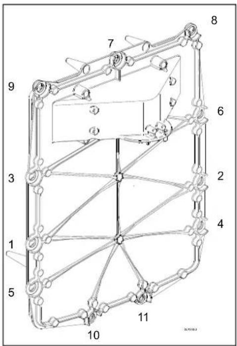
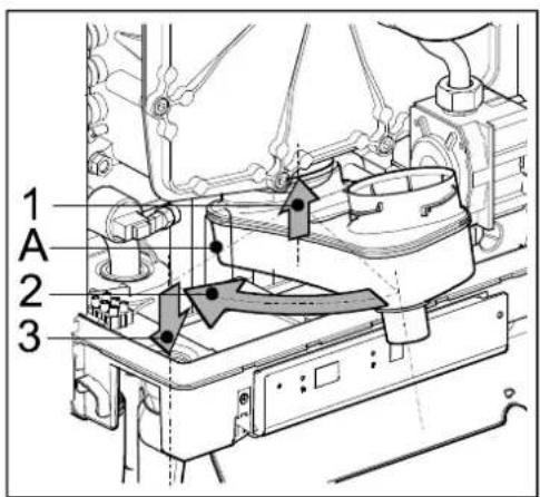
10 TECHNISCHE DATEN
© 2019 Daijin Europe NV
natural_image
Line drawing of a rectangular electronic device with a cylindrical top and mounting base (no text or symbols)natural_image
Technical line drawing of a mechanical assembly with labeled component A (no text or symbols beyond label)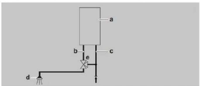
4.3 Assemblage
natural_image
Technical line drawings of mechanical components with screws and bolts (no text or symbols)natural_image
Technical line drawing of a mechanical device with internal components and housing (no text or symbols)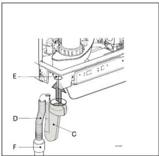
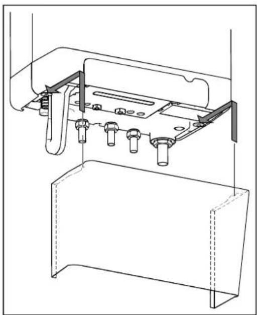
natural_image
Technical line drawing of a mechanical assembly with mounting brackets and bolts (no text or symbols)5 CONNEXION
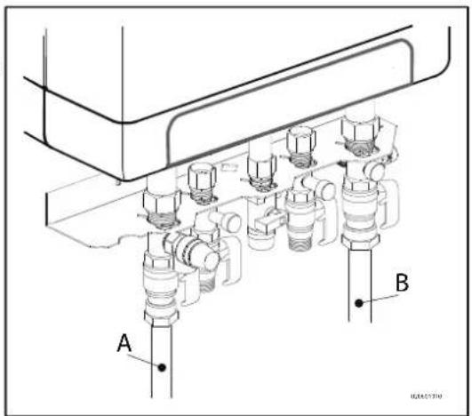
natural_image
Technical line drawing of a mechanical assembly with labeled component A (no text or symbols beyond label)
natural_image
Technical diagram of a mechanical assembly with multiple cylindrical components and a labeled component 'E' (no text or symbols beyond label)natural_image
Technical diagram of a ceiling-mounted HVAC system with airflow and ventilation duct (no text or labels)6 MISE EN SERVICE DE L'UNITE ET DE L'INSTALLATION
natural_image
Technical line drawing of a mechanical valve assembly (no text or symbols)natural_image
Technical line drawing of a mechanical device with threaded ports and a rectangular housing (no text or symbols)
line
| x | y (H/M) for 100% | y (H/M) for 75% | y (H/M) for 50% | y (H/M) for 25% | y (H/M) for A | y (H/M) for C | | ---- | ---------------- | --------------- | --------------- | --------------- | ------------- | ------------- | | 0 | 7.0 | 4.0 | 2.0 | 0.5 | 0.5 | 0.5 | | 500 | 7.0 | 4.2 | 2.1 | 0.6 | 0.8 | 1.0 | | 1000 | 6.5 | 4.0 | 2.0 | 0.7 | 1.2 | 2.0 | | 1500 | 5.5 | 3.5 | 1.8 | 0.8 | 2.0 | 3.5 | | 2000 | 4.5 | 3.0 | 1.5 | 1.0 | 3.0 | 5.0 | | 2500 | 3.5 | 2.5 | 1.2 | 1.2 | 4.0 | 6.0 | | 3000 | 2.5 | 2.0 | 1.0 | 1.5 | 5.0 | 7.0 |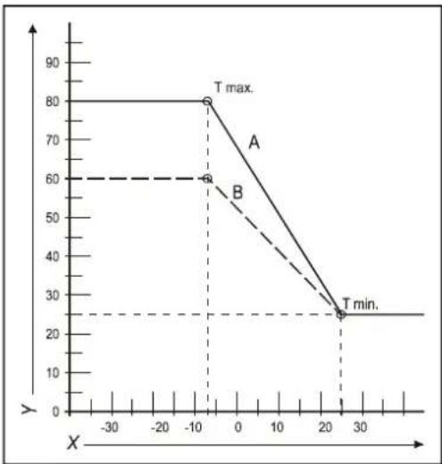
line
| X | Y | |---|---| | -10 | 80 | | -10 | 60 | | 25 | 25 | | 30 | 25 |8 DYSFONCTIONNEMENTS
Causes possibles: Solution:
Causes possibles: Solution:
Causes possibles: Solution/cause:
natural_image
Mechanical assembly diagram showing a rotating component with a curved arrow indicating motion (no text or symbols present)

9.1.3 Montage


© 2019 Daikin Europe NV
natural_image
Line drawing of a rectangular electronic device with a cylindrical top and mounting ports (no text or symbols)3 Ventileren
EHOBG\*ABV1 in combinatie met indirect gestookte boiler
| A = | Aanvoer CV | G 3/4" (ext) |
| B = | Retour CV | G 3/4" (ext) |
| C = | Gas | G 1/2" (int) |
| D = | Connensafvoer | ∅ ηn25 (flexibel) |
| h = | 517mm | EHOBG12ABV1EHOBG18ABV1 |
| H = | 590mm | EHOBG12ABV1EHOBG18ABV1 |
| Z = | Rookgasafvoer/luchttoev oer | ∅60/100 (concentrisch) |
natural_image
Technical line drawing of a mechanical assembly with labeled component A (no text or symbols beyond label)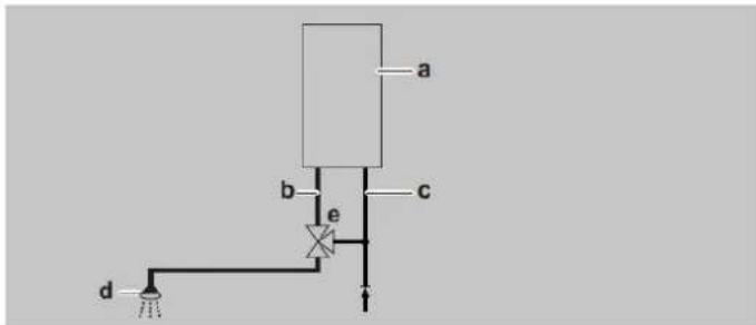
natural_image
Technical line drawings of mechanical components with bolts and screws (no text or symbols)natural_image
Technical line drawing of a mechanical device with internal components and housing (no text or symbols)4.3.3 Toestel monteren

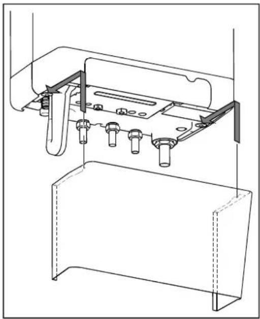
natural_image
Technical line drawing of a mechanical assembly with mounting brackets and bolts (no text or symbols)5 AANSLUITEN

Aansluitschema indirect gestookte boiler
C. Toestel
D. Tank
E. CV-installatie
F. Expansievat
G. Veiligheinsklep 3 bar
H. Driewegklep
I. Boilersensor of thermostaat
Opmerking
natural_image
Technical line drawing of a mechanical assembly with labeled component A (no text or symbols beyond label)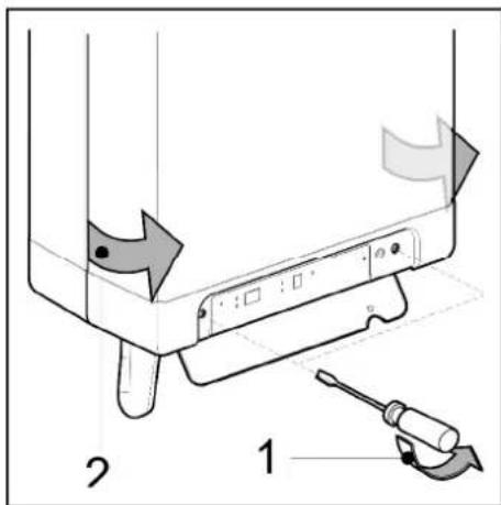
natural_image
Technical line drawing of a mechanical assembly with multiple cylindrical components and a labeled component 'E' (no text or symbols beyond label)natural_image
Technical diagram of a pipe system with airflow indicators and a battery unit (no text or symbols)6 IN BEDRIJF STELLEN VAN HET TOESTEL EN DE INSTALLATIE
natural_image
Technical line drawing of a mechanical valve assembly (no text or symbols)A → EHOBG12ABV1 & EHOBG18ABV1
X → Debiet over CV-circuit in I/u
natural_image
Technical line drawing of a mechanical device with threaded ports and a rectangular housing (no text or symbols)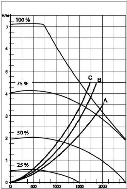
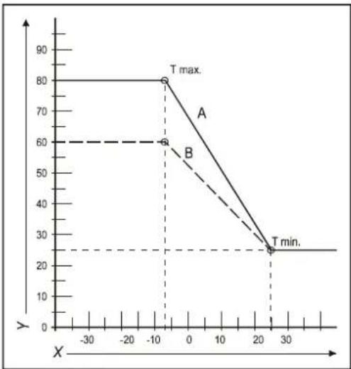
line
| X | Y | |---|---| | -10 | 80 | | -10 | 60 | | 25 | 25 | | 30 | 25 |8 STORINGEN
natural_image
Mechanical assembly diagram showing a rotating component with directional arrow (no text or symbols)
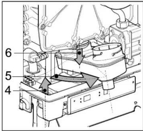
9.1.3 Monteren

natural_image
Technical illustration showing a hand adjusting a mechanical component with arrows indicating assembly (no text or symbols present)
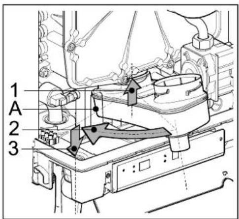
10 TECHNISCHE SPECIFICATIES
| Model EHOBG12ABV1 EHOBG18ABV1 | ||
| Verwarmingsketel met rookgasnondensor Ja Ja | ||
| Lage temperatuur-verwarmingsketel Nee Nee | ||
| Verwarmingsketel type B1 | Nee Nee | |
| Combinatieverwarmingstoestel: | Nee Nee |
| CV | |||
| Nom. belasting bovenwaarde, Qn (Hs) | kW | 4,2 – 13,9 | 6,2 – 20,8 |
| Nom. belasting onderwaarde, Qn (Hi) | kW | 3,8 – 12,5 | 5,6 – 18,7 |
| Nom. Vermogen, Pn | kW | 4,1 – 12,2 | 6,1 – 18,2 |
| Max. CV-waterdruk, PMS | bar | 3 | |
| Max. CV-watertemperatuur | °C | 90 | |
© 2019 Daikin Europe NV
natural_image
Technical line drawing of a rectangular electronic device with mounting holes and a central cylindrical component (no text or symbols)natural_image
Technical line drawing of a mechanical assembly with labeled component A (no text or symbols beyond label)natural_image
Technical line drawings of mechanical components with bolts and screws (no text or symbols)4.3.2 Montaggio del B-pack
natural_image
Technical line drawing of a mechanical device with internal components and housing (no text or symbols)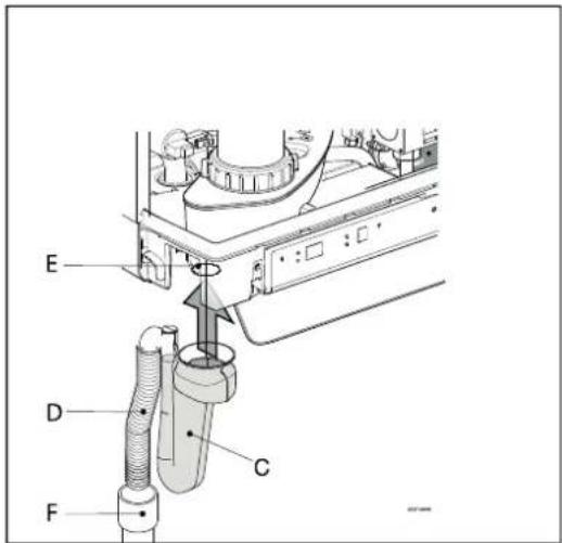
natural_image
Technical line drawing of a mechanical assembly with no visible text or symbols5 COLLEGAMENTI

natural_image
Technical line drawing of a mechanical assembly with labeled component A (no text or symbols beyond label)
natural_image
Technical diagram of a mechanical assembly with multiple cylindrical components and a labeled component 'E' (no text or symbols beyond label)natural_image
Technical diagram of a ceiling-mounted HVAC system with airflow and ventilation duct (no text or labels)natural_image
Technical line drawing of a mechanical valve assembly (no text or symbols)natural_image
Technical line drawing of a mechanical device with threaded ports and a rectangular housing (no text or symbols)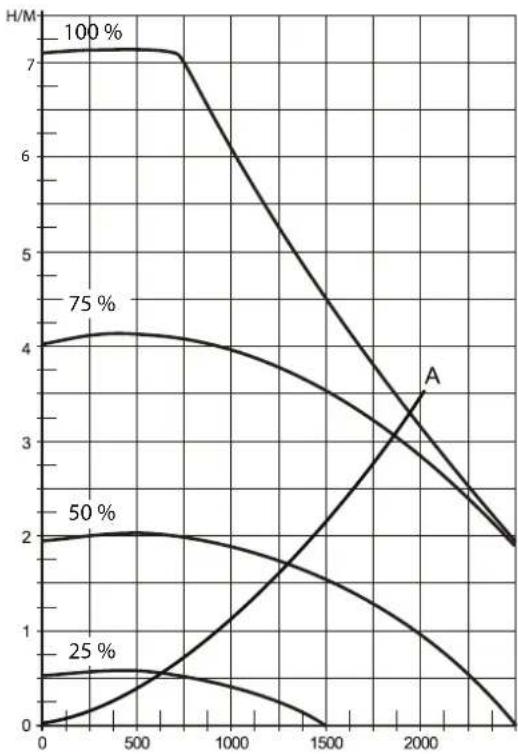
line
| x | 100 % | 75 % | 50 % | 25 % | | ---- | ----- | ---- | ---- | ---- | | 0 | 7.0 | 4.0 | 2.0 | 0.5 | | 500 | 7.0 | 4.1 | 2.1 | 0.6 | | 1000 | 7.0 | 4.0 | 2.0 | 0.5 | | 1500 | 6.0 | 3.5 | 1.8 | 0.3 | | 2000 | 4.0 | 3.0 | 1.5 | 0.1 | | 2500 | 2.0 | 2.0 | 1.0 | 0.0 |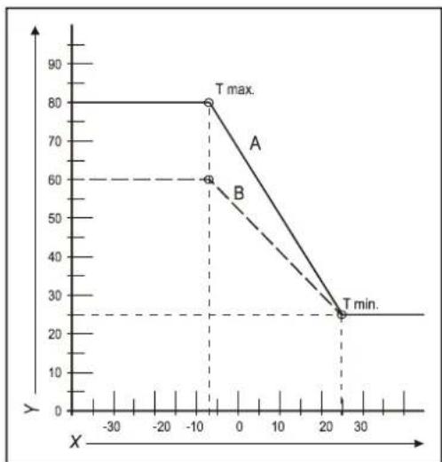
line
| X | Y | |---|---| | -10 | 80 | | -10 | 60 | | 25 | 25 |8 DIFETTI
natural_image
Mechanical assembly diagram showing a rotating component with a curved arrow indicating motion (no text or symbols present)9.1.1 Smontaggio
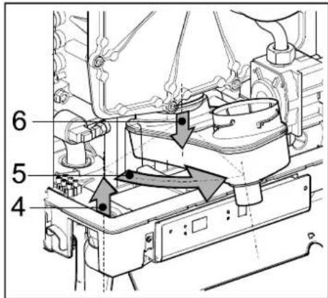
9.1.2 Pulizia

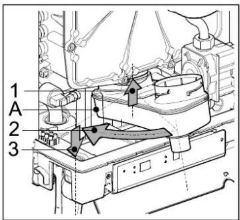
10 SPECIFICHE TECNICHE
© 2019 Daikin Europn NV
natural_image
Line drawing of a rectangular electronic device with a cylindrical top and mounting base (no text or symbols)natural_image
Technical line drawing of a mechanical assembly with labeled component A (no text or symbols beyond label)
4.3 Montaż
natural_image
Technical line drawings of mechanical components with bolts and fasteners (no text or symbols)natural_image
Technical line drawing of a mechanical device with internal components and housing (no text or symbols)natural_image
Technical line drawing of a mechanical assembly with mounting brackets and bolts (no text or symbols)5 PODŁĄCZANIE
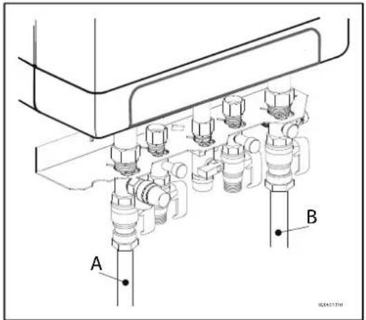
natural_image
Technical line drawing of a mechanical assembly with labeled component A (no text or symbols beyond label)
natural_image
Technical line drawing of a mechanical assembly with multiple pressure vessels and a labeled component 'E' (no text or symbols beyond label)natural_image
Technical diagram of a ceiling-mounted HVAC system with airflow and component placement (no text or labels)6 ROZRUCH URZĄDZENIA I INSTALACJI
natural_image
Technical line drawing of a mechanical valve assembly (no text or symbols)A → EHOBG12ABV1 i EHOBG18ABV1
natural_image
Technical line drawing of a mechanical device with threaded ports and a rectangular housing (no text or symbols)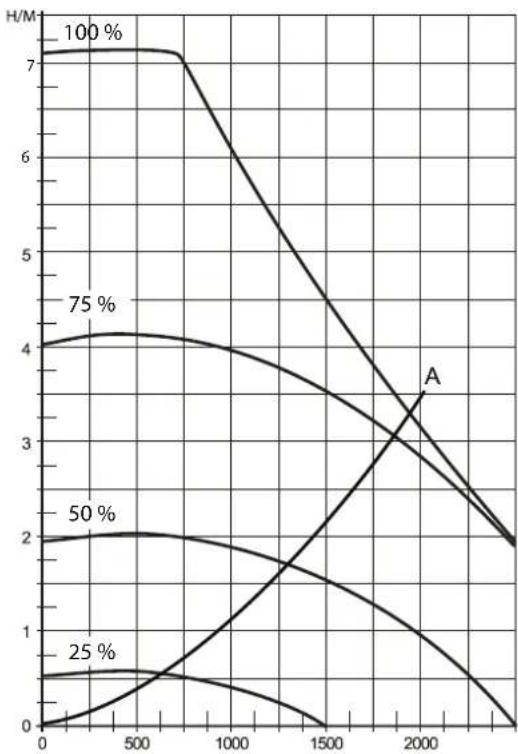
line
| x | 100% | 75% | 50% | 25% | A | | ---- | ---- | --- | --- | --- | ----- | | 0 | 7.0 | 4.0 | 2.0 | 0.5 | | | 500 | 7.0 | 4.2 | 2.1 | 0.6 | | | 1000 | 6.5 | 4.1 | 2.0 | 0.5 | | | 1500 | 5.5 | 3.8 | 1.8 | 0.3 | | | 2000 | 4.0 | 3.2 | 1.5 | 0.1 | 3.5 | | 2500 | 2.5 | 2.5 | 1.2 | 0.0 | | | 3000 | 2.0 | 2.0 | 1.0 | 0.0 | |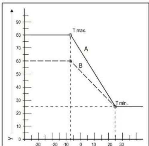
line
| Point | X-axis | Y-axis | |---|---|---| | A | -10 | 80 | | B | -10 | 60 | | T min. | 25 | 25 |8 USTERKI
natural_image
Technical line drawing of a mechanical assembly with no visible text or symbolsnatural_image
Mechanical assembly diagram showing a rotating component with directional arrow (no text or symbols)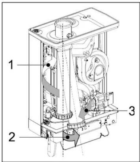

9.1.3 Montaż

natural_image
Technical illustration showing a hand adjusting a mechanical component with arrows indicating assembly steps (no text or symbols present)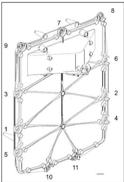

10 DANE TECHNICZNE
(1) G20 – Gaz ziemny E/H
G25 – gaz ziemny LL/L
G31 – LPG, Propan
11 WARŻNKI GWARANCJI

- EHOBG12ABV1
- EHOBG18ABV1
- Safety instructions 5
- Unit description 6
- Main components 9
- Installation 11
- Connecting 16
- Commissioning the unit and the Installation 34
- Setting and adjustment 37
- Malfunctions 44
- Maintenance 48
- Technical specifications
- Warranty conditions
- These installation instructions
- Symbols
- CAUTION
- IMPORTANT
- Service and technical support for the installer
- Identification of the product
- SAFETY INSTRUCTIONS
- UNIT DESCRIPTION
- General
- Functioning
- Operating modes
- -Off
- □ Standby
- Post-running CH
- Requested temperature reached
- Selftest
- Ventilating
- Igniting
- CH operation
- Domestic hot water operation
- EHOBG\*ABV1 in combination with indirectly fired tank
- PC Interface
- Test programs
- Frost protection
- Note
- MAIN COMPONENTS
- INSTALLATION
- Installation measurements
- Installation space
- Installing in kitchen cabinet
- Removing cover plate and front panel
- Assembly
- Assembling suspension strip and assembly bracket
- Assembling B-pack
- Assembling the unit
- Apply cover plate (optional)
- CONNECTING
- Connecting CH installation
- The CH installation must be fitted with:
- Thermostatic radiator taps
- Dividing CH installation in groups in case of additional heat sources
- Operating principle
- Installation instructions
- Connecting external tank
- Connection diagram indirectly fired tank
- Connecting electronically
- Electrical connections
- Connect room thermostat
- Room thermostat on/off
- Modulating thermostat, Open Therm
- Modulating room thermostat, wireless
- Testing the connection between the unit and the RF room thermostat
- Undo the appointment of an RF room thermostat to the CH boiler.
- Outdoor temperature sensor
- Connecting gas
- Flue7and7air7supply7duct7
- Concentric connection 60/100
- Concentric connection 80/125
- Parallel connection 80/80
- Outlet7systems7
- Flue material
- Connection to a flue system without air inlet (B23, B33)
- General assembly
- Permitted pipe lengths at parallel air supply and flue tube systems
- Connection to a sealed flue system.
- Pipe lengths
- Permitted pipe lengths in concentric flue tube systems
- General assembly:
- Permitted pipe lengths at parallel air supply and flue tube systems
- Note:
- Free in the market available flue gas materials (C63).
- Securing the flue system
- Air supply from the facade and a roof outlet with communal exhaust system
- Permitted pipe length
- Communal combustible gas outlet
- Combined flue outlet/air inlet system
- Concentric horizontal flue gas outlet, vertical part air-surrounded by shaft
- General
- Permitted pipe length and system requirements
- COMMISSIONING THE UNIT AND THE INSTALLATION
- Filling and air purge of unit and installation
- CH system
- WARNING
- DHW supply (only applicable in indirectly fired tank)
- Gas supply
- Commissioning the unit
- Reading
- Operating
- Comments
- Switching off the unit
- Frost protection
- SETTING AND ADJUSTMENT
- Direct via operating panel
- Unit on/off
- Summer mode.
- Change settings of the various functions:
- • Maximum CH supply temperature
- Control of external DHW tank
- Legionella prevention
- Resetting
- Parameter settings via the service code
- Example: Changing boiler from combi to 'hot domestic water only'
- Setting maximum CH power
- Setting pump setting
- Pressure loss graph until CH side
- Weather dependent regulation
- Fuel line graph
- Conversion to different type of gas
- Converting the dosing ring
- Gas/air regulation
- Setting gas/air regulation
- Checking the carbon dioxide setting
- Adjusting the carbon dioxide setting
- MALFUNCTIONS
- Show last malfunction
- Malfunction codes
- Other faults
- Boiler controller is noisy when igniting
- Boiler controller resonates
- No heating (CH)
- The power is reduced
- CH is not reaching correct temperature
- No hot water (only applicable in indirectly fired tank)
- DHW does not reach desired temperature (only applicable for indirectly fired tank)
- CH installation stays warm unwanted
- A-label pump LED flashes intermittently red/green
- A-label pump LED flashes red
- MAINTENANCE
- Disassembly
- Cleaning
- Fitting
- NTC resistances
- Technical Product Fiche in accordance to CELEX-32013R0811
- Electrical diagram
- Use as intended
- Environment
- INHALTSVERZEICHNIS
- Installationsort
- Montage
- ANSCHLIEßEN
- Elektroanschlüsse
- INBETRIEBNAHME DES GERÄTS UND DER INSTALLATION
- WARNUNG
- STÖRUNGEN
- Montage
- Assemblage
- CONNEXION
- MISE EN SERVICE DE L'UNITE ET DE L'INSTALLATION
- DYSFONCTIONNEMENTS
- EHOBG\*ABV1 in combinatie met indirect gestookte boiler
- Toestel monteren
- AANSLUITEN
- Aansluitschema indirect gestookte boiler
- Opmerking
- IN BEDRIJF STELLEN VAN HET TOESTEL EN DE INSTALLATIE
- STORINGEN
- Monteren
- Montaggio del B-pack
- COLLEGAMENTI
- DIFETTI
- Smontaggio
- Pulizia
- Montaż
- PODŁĄCZANIE
- ROZRUCH URZĄDZENIA I INSTALACJI
- USTERKI
- Montaż
- WARŻNKI GWARANCJI
Brand : DAIKIN
Model : EHOBG18ABV1
Category : Heating