FOB 10K-3NL - Scale Kern - Free user manual and instructions
Find the device manual for free FOB 10K-3NL Kern in PDF.

| Brand | Kern |
| Model | FOB 10K-3NL |
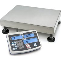
| Product type | Electronic counter scale |
| Maximum capacity (Max) | 8 kg / 15 kg (dual range) |
| Readability (d) | 1 g / 2 g |
| Repeatability | 1 g / 2 g |
| Linearity | ±3 g / ±6 g |
| Warm-up time | 30 minutes |
| Weighing units | g, lb, oz |
| Housing material | Stainless steel |
| Housing dimensions (L x W x H) | 285 x 255 x 90 mm |
| Platform dimensions | 252 x 200 x 14 mm (stainless steel) |
| Net weight | 3.8 kg |
| IP protection rating | IP67 |
| Power supply | 4 AA 1.5 V batteries or 12 V / 500 mA power adapter (230 V, 50 Hz) |
| Battery life | 48 h (backlight on) / 66 h (backlight off) |
| Tare function | Yes, via TARE key |
| Hold function | Yes, for unstable weighings |
| Tolerance weighing | Yes (with high/low thresholds and audible/visual signals) |
| Display backlight | Yes, switchable (long press TARE) |
| Auto-off | Yes, adjustable (2, 3, 4, 5 min or disabled) |
| Operating temperature | +5 °C to +35 °C |
| Operating humidity | 25 % to 95 % (non-condensing) |
| Cleaning | Soft cloth with stainless steel cleaner; avoid acids |
| Warranty | Void if opened or used improperly |
Frequently Asked Questions - FOB 10K-3NL Kern
User questions about FOB 10K-3NL Kern
0 question about this device. Answer the ones you know or ask your own.
Ask a new question about this device
Download the instructions for your Scale in PDF format for free! Find your manual FOB 10K-3NL - Kern and take your electronic device back in hand. On this page are published all the documents necessary for the use of your device. FOB 10K-3NL by Kern.
USER MANUAL FOB 10K-3NL Kern
Type FOB-S, FOB NS, FOB-NL, TFOB-NL-A, TFOB-LM-A, TFOB-A
Version 2.5
2021-11
Further language versions you will find online under www.kern-sohn.com/manuals
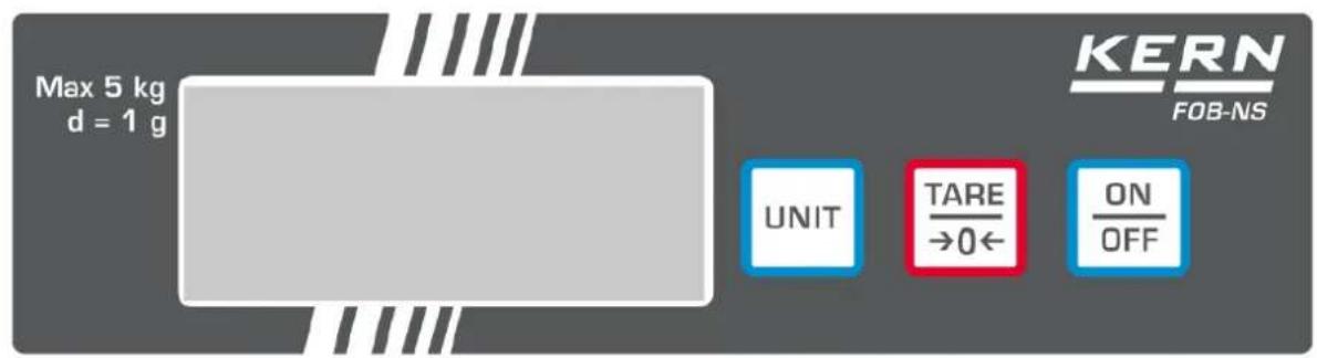
KERN FOB-NS:
KERN FOB-NL:
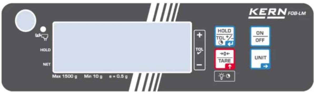
KERN FOB-LM:
KERN FOB:
Pos. Bezeichnung
Modelle FOB-NS:
Modelle FOB-NL:
Modelle FOB-LM:

Modelle FOB:
natural_image
Two concentric circles with crosshairs, one larger and one smaller, both without any text or symbols.
natural_image
Illustration of a hand holding a small object with a red arrow indicating direction (no text or symbols)natural_image
Diagram of a device rear panel with a black plug inserted, showing a red arrow pointing to the next port (no text or symbols present)natural_image
Gray rectangular object with a white circular arrow symbol on its surface (no text or labels)natural_image
Top-down view of a circular mechanical component with mounting holes and a central green pin (no text or symbols visible)natural_image
Close-up of a metallic industrial fan or fixture with four blades and central hub (no visible text or symbols)natural_image
Top-down view of a rectangular electronic device with mounting holes and a central rectangular component (no text or symbols visible)FOB-NL, FOB-LM
natural_image
Top-down view of a rectangular electronic device casing with mounting holes and internal components (no text or symbols visible)
Hold Press ON/OFF key when LCD show the version P-xxx press TARE/ZERO key to setting mold.
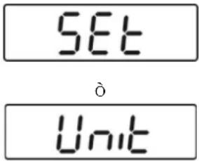
SET MESURING UNIT between g or lb
Press UNIT key to select menu Unit and then press TARE/ZERO to enter UNIT setting.
Press UNIT key to choose measuring unit.
Press TARE/ZERO key to enter measuring unit setting.
Press UNIT key to set it ON or OFF.
Press TARE/ZERO to confirm setting then return to menu Unit
Press UNIT key to select between menu.
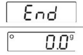
Select End and press TARE/ZERO key to save all settings.
2 Declaration of conformity 10
3 Appliance overview 11
3.1 Components 11
3.2 Keyboard overview 13
3.3 Overview of display 15
4 Basic Information (General).... 18
4.1 Proper use 18
4.2 Improper Use....18
4.3 Warranty 18
4.4 Monitoring of Test Resources.... 19
5 Basic Safety Precautions.... 19
5.1 Pay attention to the instructions in the Operation Manual.... 19
5.2 Personnel training.... 19
6 Transport and storage.... 19
6.1 Testing upon acceptance 19
6.2 Packaging / return transport 19
7 Unpacking, Setup and Commissioning 20
7.1 Installation Site, Location of Use 20
7.2 Unpacking....20
7.2.1 Placing 21
7.2.2 Levelling (FOB and FOB-LM models only).... 21
7.2.3 Scope of delivery 21
7.3 Mains connection....21
7.3.1 Assembly or disassembly of the protection hood 22
7.4 Battery operation 23
7.5 Initial Commissioning....24
7.6 Adjustment....24
8 Verification (FOB-LM models only) 27
9 Operation.... 28
9.1 Simple weighing 28
9.2 Taring.... 29
9.3 Switch-over weighing unit....29
9.4 Hold function (FOB, FOB-NL/-LM/ models only))....30
9.5 Display background illumination (FOB, FOB-NL/-LM/ models only) 30
9.6 Weighing with tolerance range (FOB, FOB-LM models only) 31
10 Menu 34
10.1 Call up menu 34
10.2 Navigation in the menu....34
10.3 Exit menu / return to weighing mode 34
10.4 Menu overview 35
10.4.1 Models FOB-S 35
10.4.2 Models FOB-NS 35
10.4.3 Models FOB-NL 36
10.4.4 Models FOB-LM 36
10.4.5 Models FOB 38
10.5 Menu settings 39
10.5.1 Setting weighing units 39
10.5.2 Automatic switch-off function „AUTO OFF“ in stand-by mode 41
11 Error reports.... 43
12 Servicing, maintenance, disposal 44
12.1 Cleaning....44
12.2 Servicing, maintenance 44
12.3 Disposal 44
13 Instant help.... 45
1 Technical data
KERN FOB-S, FOB-NS:
| KERN | FOB 500-1S | FOB 5K1S |
| Readability (d) 0.1 g 1 g | ||
| Weighing range (max) | 500 g | 5000 g |
| Reproducibility | 0.1g | 1 g |
| Linearity | ± 0.2 g | ± 2 g |
| Weighing Units | g, dwt,ozt, lb, oz | g, dwt,ozt, lb, oz |
| Recommended adjustment weight, not added (class) | 500 g (M1) | 5000 g (M1) |
| Warm-up time | 10 min | |
| Stabilization time (typical) | 2 sec. | |
| Operating temperature | + 10°C .... + 40°C | |
| Humidity of air | 25% - 95% (non-condensing) | |
| Housing stainless steel (B x D x H) mm | 170 x 150 x 40 | |
| Weighing plate, stainless steel (mm) | 120 x 150 | |
| Weight kg (net) | 650 g | |
| Auto off | 2 min | |
| Battery | 9 V block | |
| Service life 20 h | ||
| Input voltage Appliance | 9 V / 100 mA | |
| Input voltage Mains adapter | 230 V / 50 Hz | |
| KERN | FOB 0.5K-4NS | FOB 5K-3NS |
| Readability (d) 0.1 g 1 g | ||
| Weighing range (max) | 500 g | 5000 g |
| Reproducibility | 0.1g | 1 g |
| Linearity ± 0.2 g ± 2 g | ||
| Weighing Units | g, dwt,ozt, lb, oz | g, dwt,ozt, lb, oz |
| Recommended adjustment weight, not added (class) | 500 g (M1) | 5000 g (M1) |
| Warm-up time | 10 min | |
| Stabilization time (typical) | 2 sec. | |
| Operating temperature | + 10°C .... + 35°C | |
| Humidity of air | 25% - 95% (non-condensing) | |
| Housing stainless steel (B x D x H) mm | 170 x 150 x 40 | |
| Weighing plate, stainless steel (mm) | 120 x 150 x 10 | |
| Weight kg (net) | 650 g | |
| Auto off | Options: 2, 3, 4, 5, min; off | |
| Battery | 9 V block | |
| Service life 24 h | ||
| Input voltage Appliance | 9 V / 100 mA | |
| Input voltage Mains adapter | 230 V / 50 Hz | |
| IP protection | IP65 | |
FOB-NL:
| KERN | FOB 3K-4NL | FOB 7K-4NL |
| Item no./ Type | TFOB 3K-4NL-A | |
| Readability (d) | 0,2 g | 0.5 g / 1 g |
| Weighing range (max) | 3 kg | 5 kg / 7.5 kg |
| Reproducibility | 0.5 g / 1 g | 0.5 g / 1 g |
| Linearity | ± 0.6 g | ± 1.5 g / 3 g |
| Recommended adjustment weight, not added (class) | 3 kg (M1) | 5 kg (M1) |
| Warm-up time | 30 min | 30 min |
| Weighing Units | g, lb | g, lb |
| Stabilization time (typical) | 2 sec. | |
| Operating temperature | + 5°C .... + 35°C | |
| Humidity of air | 25% - 95% (non-condensing) | |
| Housing stainless steel (B x D x H) mm | 285 x 255 x 90 | |
| Weighing plate, stainless steel (mm) | 252 x 200 x 14 | |
| Weight kg (net) | 3.8 kg | |
| Auto off | 2 min | |
| Battery | 4 x 1.5 V AA | |
| Service life background illumination ON: 48 h | ||
| Service life background illumination OFF: 66 h | ||
| Input voltage Appliance | 12 V / 500 mA | |
| Input voltage Mains adapter | 230 V / 50 Hz | |
| IP protection | IP67 | |
| KERN | FOB 10K-3NL | FOB 30K-3NL |
| Readability (d) | 1 g / 2 g | 2 g / 5 g |
| Weighing range (max) | 8 kg / 15 kg | 16 kg / 30 kg |
| Reproducibility | 1 g / 2 g | 2 g / 5 g |
| Linearity | ± 3 g / 6 g | ± 6 g / 15 g |
| Recommended adjustment weight, not added (class) | 10 kg (M1) 30 kg (M1) | |
| Warm-up time | 30 min | 30 min |
| Weighing Units | g, lb, oz | g, lb, oz |
| Stabilization time (typical) | 2 sec. | |
| Operating temperature | + 5°C .... + 35°C | |
| Humidity of air | 25% - 95% (non-condensing) | |
| Housing stainless steel (B x D x H) mm | 285 x 255 x 90 | |
| Weighing plate, stainless steel (mm) | 252 x 200 x 14 | |
| Weight kg (net) | 3.8 kg | |
| Auto off | 2 min | |
| Battery | 4 x 1.5 V AA | |
| Battery | 4 x 1.5 V AA | |
| Service life background illumination ON: 48 h | ||
| Service life background illumination OFF: 66 h | ||
| Input voltage Appliance | 12 V / 500 mA | |
| Input voltage Mains adapter | 230 V / 50 Hz | |
| IP protection | IP67 | |
KERN FOB-LM:
| KERN | FOB 1K-4LM | FOB 3K-3LM |
| Item no./ Type | TFOB 1K-4LM-A | TFOB 3K-3LM-A |
| Readability (d) | 0.5 g | 1 g |
| Weighing range (max) 1.5 kg 3 kg | ||
| Verification value (e) | 0.5 g | 1 g |
| Verification class III III | ||
| Minimum weight (min) | 10 g | 20 g |
| Reproducibility | 0.5 g | 1 g |
| Linearity | ± 1.5 g | ± 2 g |
| Recommended adjustment weight, not added (class) | 1 kg (M1) | 2 kg (M1) |
| Range for zero point adjustment (A/D converter value) | 3000 - 120000 | 3000 - 120000 |
| Range for adjustment with calibration weight (A/D converter value) | 30000 – 50000 | 40000 – 65000 |
| Warm-up time | 10 min | 10 min |
| Weighing unit | g | g |
| Stabilization time (typical) | 2 sec. | |
| Operating temperature | + 0°C .... + 40°C | |
| Humidity of air | 25% - 95% (non-condensing) | |
| Housing (B x D x H) mm | 285 x 255 x 90 | |
| Weighing plate, stainless steel (mm) | 252 x 200 x 14 | |
| Weight kg (net) | 3.8 kg | |
| Auto off | 2 min | |
| Battery | 4 x 1.5 V AA | |
| Service life background illumination ON: 48 h | ||
| Service life background illumination OFF: 66 h | ||
| Input voltage Appliance | 12 V / 500 mA | |
| Input voltage Mains adapter | 230 V / 50 Hz | |
| IP protection | IP67 | |
| KERN | FOB 6K-3LM | FOB 10K-3LM |
| Item no./ Type | TFOB 6K-3LM -A | TFOB 10K-3LM-A |
| Readability (d) 2 g 5 g | ||
| Weighing range (max) 6 kg 15 kg | ||
| Verification value (e) 2 g 5 g | ||
| Verification class III III | ||
| Minimum weight (min) | 40 g | 100 g |
| Reproducibility | 2 g | 5 g |
| Linearity | ± 4 g | ± 10 g |
| Recommended adjustment weight, not added (class) | 5 kg (M1) | 10 kg (M1) |
| Range for zero point adjustment (A/D converter value) | 3000 - 120000 | 3000 - 10000 |
| Range for adjustment with calibration weight (A/D converter value) | 55000 – 80000 | 55000 – 80000 |
| Warm-up time | 10 min | 10 min |
| Weighing unit | g | kg |
| Stabilization time (typical) | 2 sec. | |
| Operating temperature | + 0°C .... + 40°C | |
| Humidity of air | 25% - 95% (non-condensing) | |
| Housing (B x D x H) mm | 285 x 255 x 90 | |
| Weighing plate, stainless steel (mm) | 252 x 200 x 14 | |
| Weight kg (net) | 3.8 kg | |
| Auto off | 2 min | |
| Battery | 4 x 1.5 V AA | |
| Service life background illumination ON: 48 h | ||
| Service life background illumination OFF: 66 h | ||
| Input voltage Appliance | 12 V / 500 mA | |
| Input voltage Mains adapter | 230 V / 50 Hz | |
| IP protection | IP67 | |
KERN FOB:
| KERN | FOB 1.5K0.5 | FOB 3K1 | FOB 6K2 |
| Item no./ Type | TFOB 1K-4-A | TFOB 3K-3-A | TFOB 6K-3-A |
| Readability (d) | 0.5 g | 1 g | 2 g |
| Weighing range (max) | 1.5 kg | 3 kg | 6 kg |
| Reproducibility | 0.5 g | 1 g | 2 g |
| Linearity | 1.5 g | 3 g | 6 g |
| Recommended adjustment weight, not added (class) | 1.5 kg (M1) | 3 kg (M1) | 6 kg (M1) |
| Warm-up time | 10 min | ||
| Weighing Units | g, lb | g, lb | g, lb |
| Stabilization time (typical) | 2 sec. | ||
| Operating temperature | + 5°C .... + 35°C | ||
| Humidity of air | 25% - 95% (non-condensing) | ||
| Housing (B x D x H) mm | 235 x 175 x 62 | ||
| Weighing plate, stainless steel (mm) | 175 x 165 x 7 | ||
| Weight kg (net) | 1.8 kg | ||
| Auto off | 2 min | ||
| Rechargeable battery | Standard | ||
| Input voltage Appliance | 12 V / 500 mA | ||
| Input voltage Mains adapter | 100V - 240 V, 50 Hz | ||
2 Declaration of conformity
The current EC/EU Conformity declaration can be found online in:
www.kern-sohn.com/ce
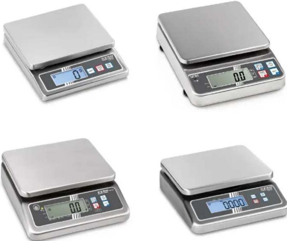
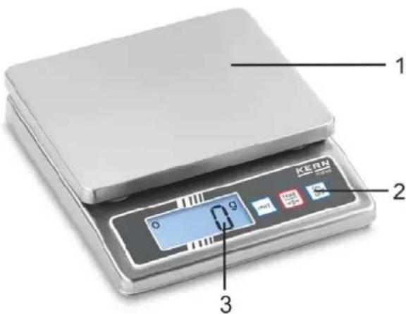
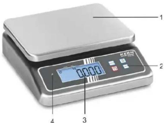
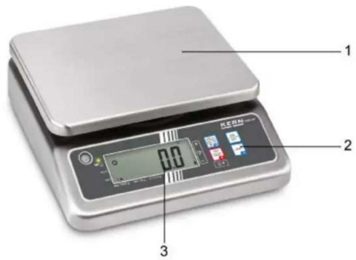
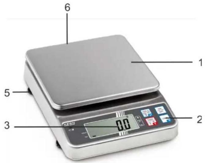
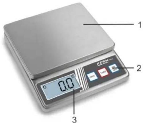
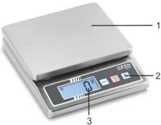
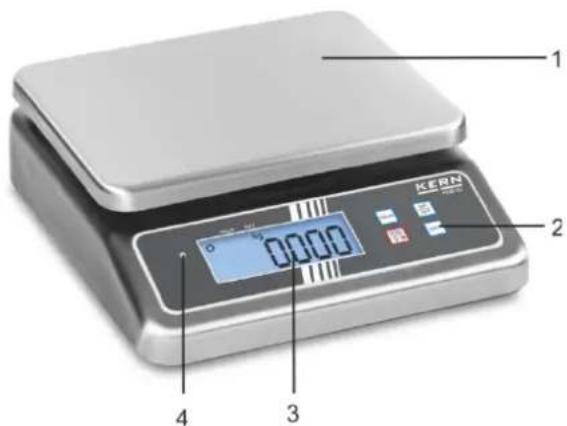
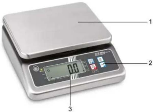
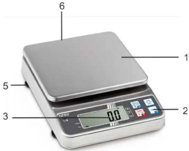
3 Appliance overview
3.1 Components
KERN FOB-S:
KERN FOB-NS:
KERN FOB-NL:
KERN FOB-LM:
KERN FOB:
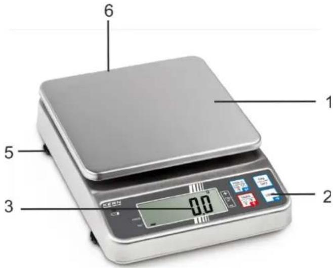
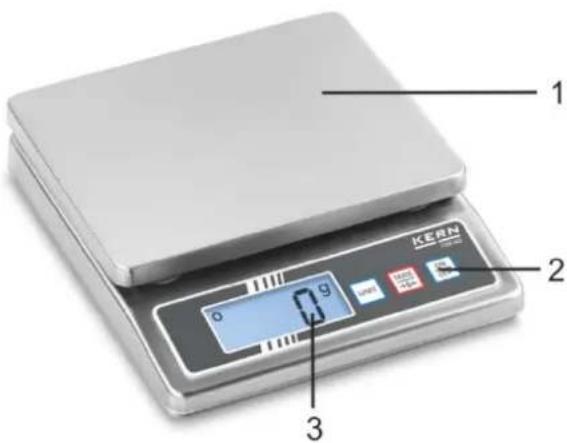
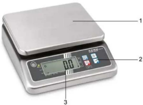
Pos. Description
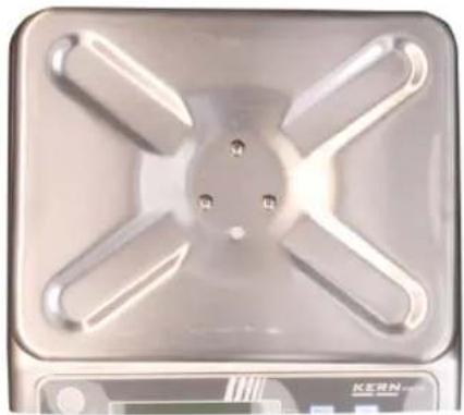
1 Weighing pan
2 Keyboard
3 Display
4 Rechargeable battery charge display
5 Levelling screw
6 Bubble level (below weighing pan)
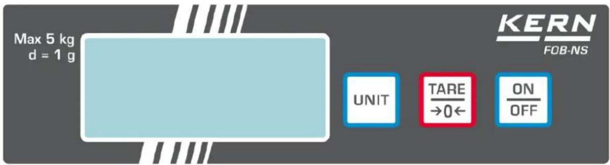
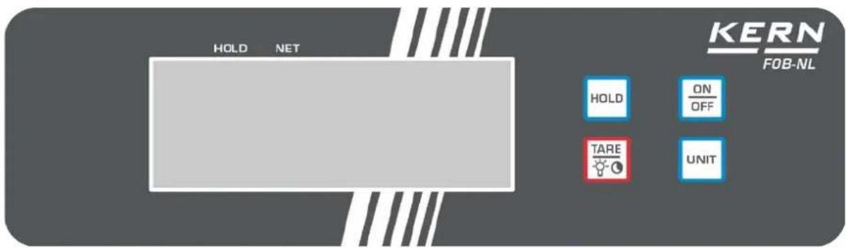
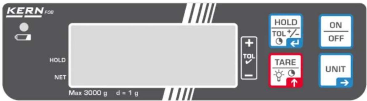
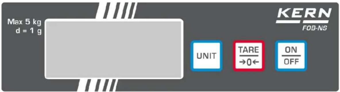
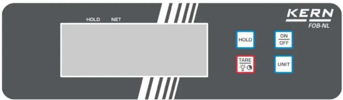
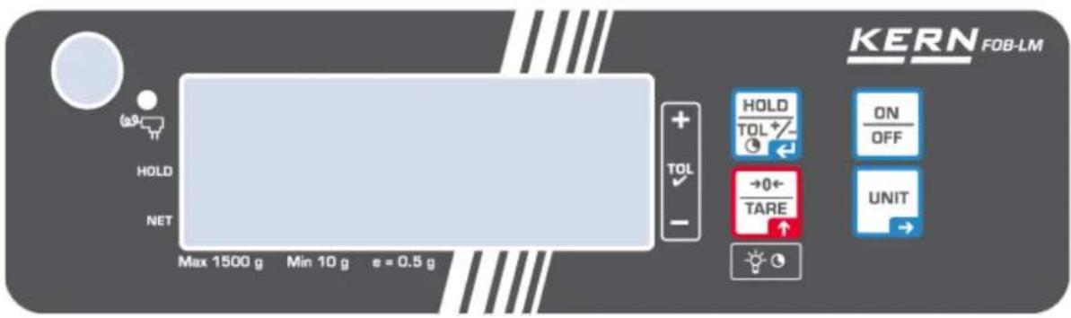
3.2 Keyboard overview
| Button | Description | Description |
 | ON/OFF-button | Turn on/off |
 | TARE-key | TaringZeroing |
 | ||
 | TaringZeroingSwitching the display background illumination on/off (long key press) | |
 | TaringZeroingSwitching the display background illumination on/off (long key press) | |
 | UNIT-button | Switch-over weighing unit |
 | HOLD button | Call up hold functionCalling up tolerance weighing (FOB models only) |
Models FOB-S:

Models FOB-NS:
Models FOB-NL:

Models FOB-LM:
Models FOB:

3.3 Overview of display
Models FOB-S / FOB-NS:
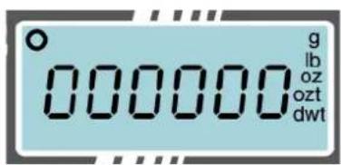
Display Description
g, lb, oz, ozt, dwt
O
Weighing units
Stability display
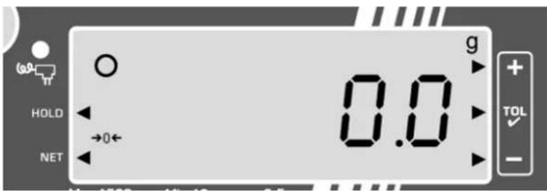
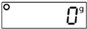
Models FOB-NL:
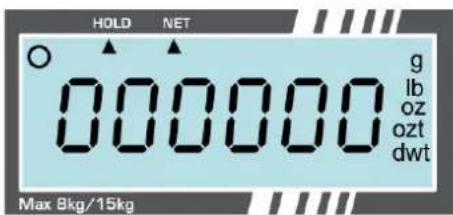
Display Description
g, lb, oz, ozt, dwt
0
HOLD
NET
Weighing Units
Stability display
Display hold function
Display net weight
Models FOB-LM:
Display Description
g


Weighing unit
Stability display
Zero display
Battery charge display
When the display shows that the battery capacity is exhausted, the balance will automatically switch off after 30 seconds.
LED lights up when the power adapter is connected
The next to the icon is displayed when:
HOLD
NET
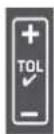
the data-hold function is active
the weight value is a net weight value
the balance is in tolerance weighing mode
Models FOB:
Display Description
g


Weighing unit
Stability display
Zero display
Rechargeable battery charge display
Rechargeable battery charge display
- LED lights green when the rechargeable battery is fully charged
- LED flashes green when rechargeable battery is being charged
The ▶ next to the icon is displayed when:
HOLD
NET
the data-hold function is active
the weight value is a net weight value
the balance is in tolerance weighing mode
4 Basic Information (General)
4.1 Proper use
The balance you purchased is intended to determine the weighing value of material to be weighed. It is intended to be used as a “non-automatic balance”, i.e. the material to be weighed is manually and carefully placed in the centre of the weighing pan. As soon as a stable weighing value is reached the weighing value can be read.
4.2 Improper Use
Do not use balance for dynamic weighing. In the event that small quantities are removed or added to the material to be weighed, incorrect weighing results can be displayed due to the “stability compensation”. (Example: Slowly draining fluids from a container on the balance.)
Do not leave permanent load on the weighing pan. This may damage the measuring system.
Impacts and overloading exceeding the stated maximum load (max) of the balance, minus a possibly existing tare load, must be strictly avoided. Balance may be damage by this.
Never operate balance in explosive environment. The serial version is not explosion protected.
The structure of the balance may not be modified. This may lead to incorrect weighing results, safety-related faults and destruction of the balance.
The balance may only be used according to the described conditions. Other areas of use must be released by KERN in writing.
4.3 Warranty
Warranty claims shall be voided in case
• Our conditions in the operation manual are ignored
- The appliance is used outside the described uses
• The appliance is modified or opened
- Mechanical damage and damage caused by media, liquids,
Natural wear and tear
- The appliance is improperly set up or incorrectly electrically connected
• The measuring system is overloaded
4.4 Monitoring of Test Resources
In the framework of quality assurance the measuring-related properties of the balance and, if applicable, the testing weight, must be checked regularly. The responsible user must define a suitable interval as well as type and scope of this test. Information is available on KERN's home page (www.kern-sohn.com with regard to the monitoring of balance test substances and the test weights required for this. In KERN's accredited DKD calibration laboratory test weights and balances may be calibrated (return to the national standard) fast and at moderate cost.
5 Basic Safety Precautions
5.1 Pay attention to the instructions in the Operation Manual

Carefully read this operation manual before setup and commissioning, even if you are already familiar with KERN balances.
5.2 Personnel training
The appliance may only be operated and maintained by trained personnel.
6 Transport and storage
6.1 Testing upon acceptance
When receiving the appliance, please check packaging immediately, and the appliance itself when unpacking for possible visible damage.
6.2 Packaging / return transport

Keep all parts of the original packaging for a possibly required return.
→ Only use original packaging for returning.
Prior to dispatch disconnect all cables and remove loose/mobile parts.
→ Reattach possibly supplied transport securing devices.
→ Secure all parts such as the glass wind screen, the weighing platform, power unit etc. against shifting and damage.
7 Unpacking, Setup and Commissioning
7.1 Installation Site, Location of Use
The balances are designed in a way that reliable weighing results are achieved in common conditions of use.
You will work accurately and fast, if you select the right location for your balance.
Therefore, observe the following for the installation site:
- Place the balance on a firm, level surface;
- Avoid extreme heat as well as temperature fluctuation caused by installing next to a radiator or in the direct sunlight;
- Protect the balance against direct draughts due to open windows and doors;
- Avoid jarring during weighing;
- Protect the balance against high humidity, vapours and dust;
- Do not expose the device to extreme dampness for longer periods of time. Non-permitted condensation (condensation of air humidity on the appliance) may occur if a cold appliance is taken to a considerably warmer environment. In this case, acclimatize the disconnected appliance for ca. 2 hours at room temperature.
- Avoid static charge of weighed items or weighing container.
Major display deviations (incorrect weighing results) may be experienced should electromagnetic fields (e.g. due to mobile phones or radio equipment), static electricity accumulations or instable power supply occur. Change location or remove source of interference.
7.2 Unpacking
Carefully remove the weighing balance from the packaging and install it at the designated work place.
7.2.1 Placing
The balance must be installed in a way that the weighing plate is exactly in horizontal position.
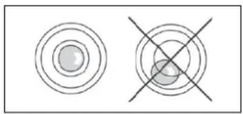
7.2.2 Levelling (FOB and FOB-LM models only)
Level balance with foot screws until the air bubble of the water balance is in the prescribed circle.
natural_image
Two circular diagrams with concentric rings and intersecting lines, no text or symbols presenti
Check levelling regularly.
7.2.3 Scope of delivery
Serial accessories:
• Balance
- Weighing pan
- Mains adapter (standard, FOB models only)
- Battery (all models except FOB models)
- Rechargeable battery (standard, FOB models only)
- Protective cover
- Operating manual
- Mains adapter (option KERN FOB-A01, all models except models FOB)
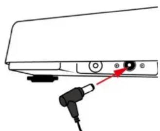
7.3 Mains connection
The balance may be operated via the optional mains adapter. The stated voltage value must be the same as the local voltage. Only use original KERN mains adapters. Using other makes requires consent by KERN.

natural_image
Line drawing of a hand holding a small tool near a mechanical component (no text or symbols)Illustration example KERN FOB-LM
natural_image
Diagram of a device rear panel with a black connector and red arrow pointing to a button (no text or symbols)Illustration example KERN FOB
7.3.1 Assembly or disassembly of the protection hood Models FOB-S, FOB-NS, FOB-NL, FOB
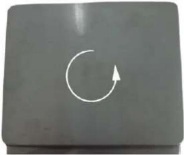 | → Unlock weighing pan in the direction of the arrow |
 | → Remove or replace the protection hood |
Models FOB-LM:
 | Fasten the weighing plate support on the balance with the help of the three delivered screws.After that attach the weighing plate. |
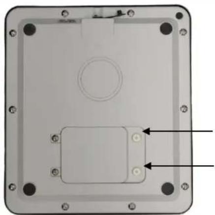
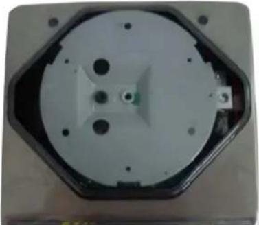
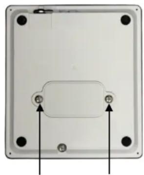
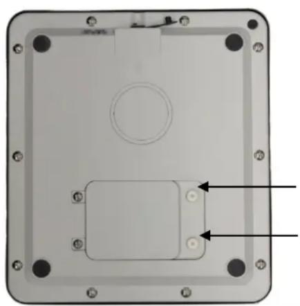
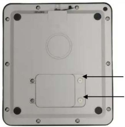
7.4 Battery operation
Remove battery cover at the lower side of the housing. Insert Battery, see. Chap. 1 "Technical Data".
Put battery cover back in place and tighten it.
Illustration example:
FOB-NS
natural_image
Back view of a rectangular electronic device with mounting holes and a central component (no text or symbols visible)FOB-NL, FOB-LM
natural_image
Interior view of a rectangular electronic device with mounting holes and a central circular component (no text or symbols visible)
When you tighten the battery cover, make sure that not too much pressure is put on the weighing plate. The load cell may be damaged.
In the menu you can activate the AUTO-OFF function (see chap. 10.5.2 "Automatic switch-off function"). According to the selected settings, the balance switches automatically off in order to spare the battery.
The empty battery is indicated on the display by „LobAt“. Press ON/OFF-key and replace the battery/ies immediately.
If the balance is not used for a longer time, take out the battery/ies and store it/them separately. Leaking battery liquid could damage the balance.
7.5 Initial Commissioning
In order to obtain exact results with the electronic balances, your balance must have reached the operating temperature (see warming up time chap. 1). During this warming up time the balance must be connected to the power supply (mains or battery).
The accuracy of the balance depends on the local acceleration of gravity.
Strictly observe hints in chapter Adjustment.
7.6 Adjustment
As the acceleration value due to gravity is not the same at every location on earth, each balance must be coordinated - in compliance with the underlying physical weighing principle - to the existing acceleration due to gravity at its place of location (only if the balance has not already been adjusted to the location in the factory). This adjustment process must be carried out for the first commissioning, after each change of location as well as in case of fluctuating environment temperature. To receive accurate measuring values it is also recommended to adjust the balance periodically in weighing operation.
The adjustment should be made with the recommended adjustment weights (see chap. 1 "Technical data").
Procedure when adjusting:
Observe stable environmental conditions.
A warming up time (see chapter 1; Technical Data) is required for stabilization.
Ensure that there are no objects on the weighing plate.
Models FOB-S, FOB-NS, FOB-NL, FOB::
| Balance display Operation | |
 ò ò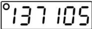 (example) (example) | Switch off the balanceHold down the ON/OFF key, simultaneously press the UNIT key 3 times, release the ON/OFF key - an internal numerical value is displayed. |
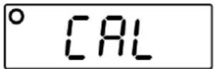
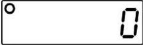 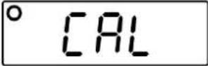 ò ò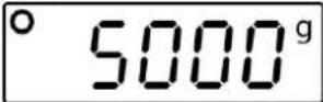 (example) (example)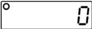 | Press the TARE key, "0" is displayedPut adjustment weight centrically on the weighing plate and press the TARE-key, "CAL" is displayed, followed by the value of the put adjustment weight.Take away adjustment weightThe balance changes into weighing mode.Adjustment has now been completed successfully. |
Models FOB-LM:

- Following each calibration, the integrated counter value (
) is increased by one. - If the service menu is brought up after the password has been entered, the verification is lost, as the value of the integrated counter (
) is increased by '1'.
Calibration procedure:

- If the calibration menu is brought up after the password has been entered, the verification is lost, as the value of the integrated counter (
| Balance indication Operation | |
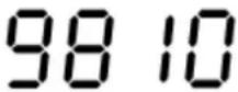
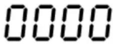 | Switch the balance off. Press the ON/OFF button and hold it down. When the ON/OFF is held down and Con x value is displayed, press UNIT 3 times. Then release the ON/OFF button. A "0000" password request will be displayed. Enter "9810" or "9788"password. When you press TARE, the numerical value will be increased; when you press UNIT, the decimal position is changed. To confirm the entered data, press ON/OFF button The integrated counter value will be displayed. Press TARE to confirm, "00" will be displayed. |
 | |
 ↓ ↓  (example) (example) 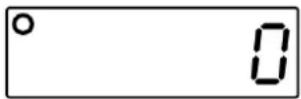 | Put on a calibration weight (see chapter. 1 Technical data). Wait until the stabilisation indicator is displayed, press TARE to confirm. "CAL" will be displayed. The balance will switch to the weighing mode. Switch the balance off and then on again. Con value will be increased by "1". This means the calibration has been completed successfully. |
8 Verification (FOB-LM models only)
General introduction:
According to EU directive 2014/31/EU balances must be officially verified if they are used as follows (legally controlled area):
a) For commercial transactions if the price of goods is determined by weighing.
b) For the production of medicines in pharmacies as well as for analyses in the medical and pharmaceutical laboratory.
c) For official purposes
d) For manufacturing final packages
In cases of doubt, please contact your local trade in standard.
Verification notes:
An EU type approval exists for balances described in their technical data as verifiable. If a balance is used where obligation to verify exists as described above, it must be verified and re-verified at regular intervals.
Re-verification of a balance is carried out according to the respective national regulations. The validity for verification of balances in Germany is e.g. 2 years.
The legal regulation of the country where the balance is used must be observed!
i
Verification of the balance is invalid without the seal.
The seal marks attached on balances with type approval point out that the balance may only be opened and serviced by trained and authorised specialist staff. If the seal mark is destroyed, verification looses its validity. Please observe all national laws and legal regulations. In Germany a reverification will be necessary.
9 Operation
9.1 Simple weighing
| Balance display Operation | |
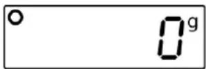
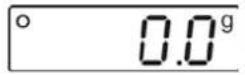
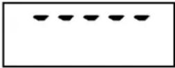
 | Turn on balance by pressing the ON/OFF key.The balance will carry out a self-test.Await zero display |
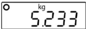
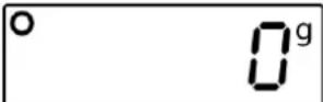 | Should the balance not display exactly "0" despite unloaded weighing pan, press the TARE key. The balance returns to „0“ |
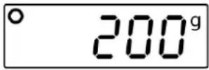
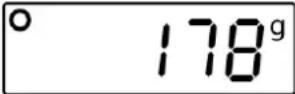 (example) (example) | Place weighed items on balance.Wait until the stability display appears.Read weighing result. |
| To turn off the balance, press the ON/OFF-key shortly. |
9.2 Taring
The dead weight of any weighing container may be tared away by pressing a button, so that the following weighing procedures show the net weight of the goods to be weighed.
| Balance display Operation | |
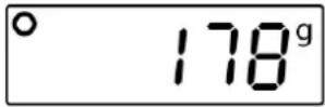
 (example) (example) | Deposit weighing container.The weight of the container is displayed. |
 | Press theTAREbutton, the zero display disappears.The weight of the container is now internally saved. |
 (Example FOB-NS) (Example FOB-NS)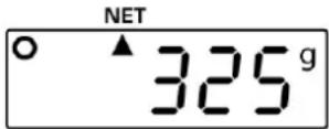 (Example FOB-NL) (Example FOB-NL) | Place weighed items in the weighing container.The net weight of the weighed items is displayed.For L models, a triangle appears below the NET symbol. |
9.3 Switch-over weighing unit
According to the requirements the balance can be switched over into different units. These are set in the menu.
In the weighing mode, press the UNIT key to toggle to the selected weighing units.
| i | The available weighing units depend on the model and verification of the balance, see chap.1 "Technical data".When switching- on the balance, the unit in which the balance has been switched off, will be displayed. |
9.4 Hold function (FOB, FOB-NL/-LM/ models only))
The balance has an integrated standstill function (mean value calculation).
With this it is possible to weigh unstable samples to be weighed exactly.
There are 2 possibilities:
| Balance display | Operation |
 | Turn on balance by pressing the ON/OFF key.The balance will carry out a self-test.Wait for „0“ display |
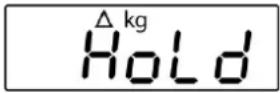 | Put the weighed item in place and press the HOLD key; "HOLD" will appear and a small triangle flashes. During this time, an average value is recorded. |
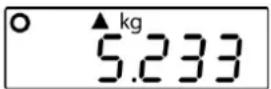 (example) (example) | The triangle will stop flashing, the stability display appears and the weight value obtained is displayed. |
 | By pressing the HOLD button several times, the balance returns to weighing mode. The triangle disappears. |
9.5 Display background illumination (FOB, FOB-NL/-LM/ models only)
The balance has the ability to turn the backlight of the display on or off.
⇒ Press the TARE key for approx. 3 sec.
9.6 Weighing with tolerance range (FOB, FOB-LM models only)
You can set an upper or lower limit when weighing with tolerance range and thus ensure that the weighed load remains exactly within the set limits.
During tolerance tests such as dosing, portioning and sorting the unit will indicate exceeded or undershot limits by emitting an optical or acoustic signal.
| Displayed triangle next to | Weight of the weighed item | Acoustic signal | Optical signal / background illumination of the display |
| √ | Target weight within tolerance range | 2 short beeps | 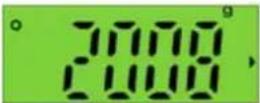 |
| - | Target weight below lower tolerance limit | no beep |  |
| + | Target weight above upper tolerance limitIfis displayed, the maximum load of the balance is exceeded. | perpetual tone | 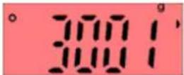 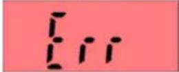 |
Call function:
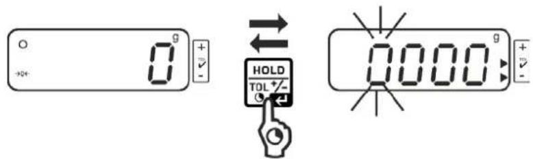
- Press and hold the HOLD key for three seconds in the weighing mode. The tolerance weighing mode is displayed. The display for entering the lower limit value appears, the first digit flashes. The lower tolerance mark is displayed.
Set limit values:
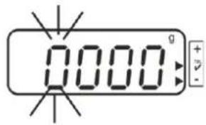
- To change the flashing digit, press the TARE button repeatedly until the desired value is displayed. Select the next digit with the UNIT key and set the value with the TARE key.
- Repeat process for each digit.
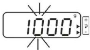
- Confirm entry with the HOLD key. The display for entering the upper limit value appears, the first digit flashes. The upper tolerance mark is displayed. The display lights red.
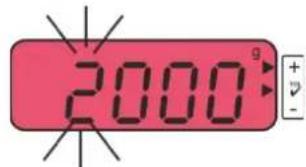
- To change the flashing digit, press the TARE button repeatedly until the desired value is displayed. Select the next digit with the UNIT key and set the value with the TARE key. Repeat process for each digit.
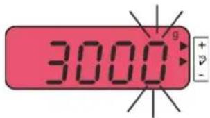
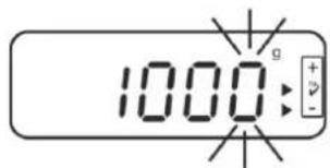
- Finish the input with the HOLD-key, from here, you can determine whether the weighed item is within the two tolerance limits.
Tolerance weighing
→ Tare when using a weighing container.
⇒ Put on goods to be weighed, tolerance control is started. The visual and acoustic signals indicate whether the weighed item is within the two tolerance limits.
| Load below specified tolerance | Load within specified tolerance | Load exceeds specified tolerance |
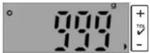 The tolerance mark ▶next to "-" is displayed The tolerance mark ▶next to "-" is displayed | 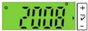 The tolerance mark ▶next to "√" is displayed The tolerance mark ▶next to "√" is displayed | 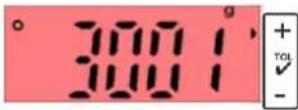 The tolerance mark ▶next to "+" is displayed The tolerance mark ▶next to "+" is displayed |
Return to weighing mode:
- Press and hold the HOLD key for three seconds to exit the tolerance weighing mode
10 Menu
10.1 Call up menu
| Models FOB-S/-NS | In weighing mode, hold down the TARE key untilfollowed byis displayed. |
| Models FOB-NS | In weighing mode, hold down the TARE key untilfollowed byis displayed. |
| Models FOB-NL/-LM | Switch off the balancePress and hold the ON/OFF key. Press the TARE key 3 times simultaneously, then release both keys.followed byis displayed. |
| Models FOB | Switch off the balance.Press the ON/OFF and TARE buttons simultaneously and for approx. 3 s untilis displayed, then release both keys. |
| Models FOB-LM | In the weighing mode press and hold UNIT button untiland thenis displayed. |
10.2 Navigation in the menu
All models (except FOB):
| Button | Navigation | Description |
| TARE-key | [120] | Passing through menu items from top to bottomConfirm selection |
| UNIT-button |  | Passing through menu items from left to right |
Models FOB:
| Button | Navigation | Description |
| UNIT-button | 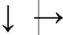 | Passing through menu items from left to right |
| TARE-key | Confirm selection |
10.3 Exit menu / return to weighing mode
⇒ Select menu item
10.4 Menu overview
10.4.1 Models FOB-S
flowchart
graph TD
A["SET"] --> B["Unit"]
B --> C["R.OFF"]
C --> D["CAP"]
D --> E["End"]
B --> F["120 S"]
F --> G["180 S"]
G --> H["240 S"]
H --> I["300 S"]
I --> J["OFF"]
B --> K["g"]
K --> L["Ib"]
L --> M["oz"]
M --> N["Ib/oz"]
N --> O["dwt"]
O --> P["ozt"]
P --> Q["OZ"]
Q --> R["Oz"]
R --> S["ON"]
S --> T["OFF"]
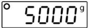
C --> U["200.0⁹"]
U --> V["500.0⁹"]
V --> W["1200.0⁹"]
W --> X["2500.0⁹"]
X --> Y["5000.⁹"]
V --> Z["1"]
Z --> AA["2"]
* Preset values may only be modified by trained and specialized personnel.
| 1 | Model FOB 500-1S |
| 2 | Model FOB 5K1S |
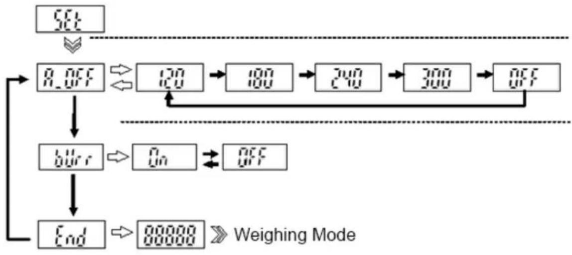
10.4.2 Models FOB-NS
flowchart
graph TD
    A["SET"] --> B["R.OFF"]
    B --> C["End"]
    B --> D["1205"]
    D --> E["1805"]
    E --> F["2405"]
    F --> G["3005"]
    G --> H["OFF"]
10.4.3 Models FOB-NL
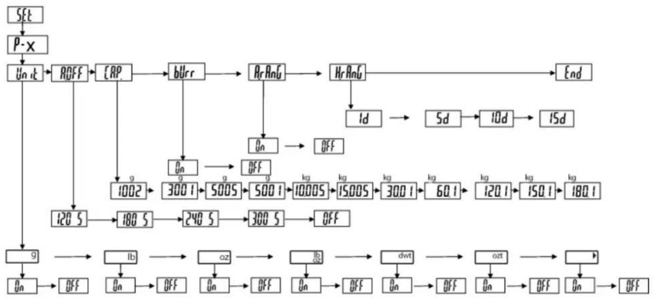
flowchart
graph TD
    A["SET"] --> B["P-X"]
    B --> C["Un it"]
    C --> D["ROFF"]
    D --> E["CRP"]
    E --> F["bUrr"]
    F --> G["ArAnG"]
    G --> H["HrAnG"]
    H --> I["End"]
    C --> J["120.5"]
    J --> K["180.5"]
    K --> L["240.5"]
    L --> M["300.5"]
    M --> N["OFF"]
    C --> O["g"]
    O --> P["1002"]
    P --> Q["3001"]
    Q --> R["5005"]
    R --> S["5001"]
    S --> T["10005"]
    T --> U["15005"]
    U --> V["3001"]
    V --> W["60.1"]
    W --> X["120.1"]
    X --> Y["150.1"]
    Y --> Z["180.1"]
    C --> AA["g"]
    AA --> AB["On"]
    AB --> AC["Off"]
    C --> AD["Ib"]
    AD --> AE["On"]
    AE --> AF["Off"]
    C --> AG["oz"]
    AG --> AH["On"]
    AH --> AI["Off"]
    C --> AJ["Ib/oz"]
    AJ --> AK["On"]
    AK --> AL["Off"]
    C --> AM["dwt"]
    AM --> AN["On"]
    AN --> AO["Off"]
    C --> AP["ozt"]
    AP --> AQ["On"]
    AQ --> AR["Off"]
    C --> AS["On"]
    AS --> AT["Off"]
10.4.4 Models FOB-LM
Verified:

Menu items relevant for verification are not available for verified balances.
flowchart
graph TD
A["SET"] --> B["R_OFF"]
B --> C["120"]
C --> D["180"]
D --> E["240"]
E --> F["300"]
F --> G["OFF"]
G --> H["ERR"]
H --> I["On"]
I --> J["OFF"]
J --> K["End"]
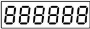
K --> L["88888"]
L --> M["Weighing Mode"]
Not verified:

On non-verified balances, the contacts on the PCB must be short-circuited with a jumper. All menu items are available.
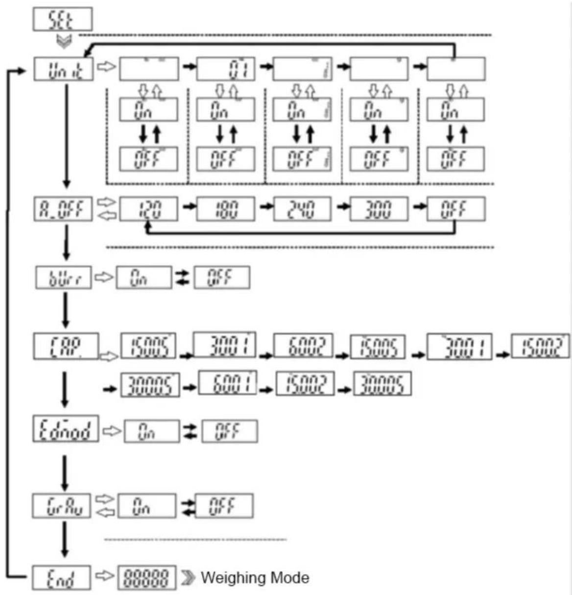
flowchart
graph TD
    A["SET"] --> B["Un OK"]
    B --> C{0?}
    C -->|Yes| D["Off"]
    C -->|No| E["On"]
    E --> F{0?}
    F -->|Yes| G["Off"]
    F -->|No| H["On"]
    H --> I{0?}
    I -->|Yes| J["Off"]
    I -->|No| K["On"]
    K --> L{0?}
    L -->|Yes| M["Off"]
    L -->|No| N["On"]
    N --> O{0?}
    O -->|Yes| P["Off"]
    O -->|No| Q["On"]
    Q --> R{0?}
    R -->|Yes| S["Off"]
    R -->|No| T["On"]
    T --> U{0?}
    U -->|Yes| V["Off"]
    U -->|No| W["On"]
    W --> X{0?}
    X -->|Yes| Y["Off"]
    X -->|No| Z["On"]
    Z --> AA{0?}
    AA -->|Yes| AB["Off"]
    AA -->|No| AC["On"]
    AC --> AD{0?}
    AD -->|Yes| AE["Off"]
    AD -->|No| AF["On"]
    AF --> AG{0?}
    AG -->|Yes| AH["Off"]
    AG -->|No| AI["On"]
    AI --> AJ{0?}
    AJ -->|Yes| AK["Off"]
    AJ -->|No| AL["On"]
    AL --> AM{0?}
    AM -->|Yes| AN["Off"]
    AM -->|No| AO["On"]
    AO --> AP{0?}
    AP -->|Yes| AQ["Off"]
    AP -->|No| AR["On"]
    AR --> AS{0?}
    AS -->|Yes| AT["Off"]
    AS -->|No| AU["On"]
    AU --> AV{0?}
    AV -->|Yes| AW["Off"]
    AV -->|No| AX["On"]
    AX --> AY{0?}
    AY -->|Yes| AZ["Off"]
    AY -->|No| BA["On"]
    BA --> BB{0?}
    BB -->|Yes| BC["Off"]
    BB -->|No| BD["On"]
    BD --> BE{0?}
    BE -->|Yes| BF["Off"]
    BE -->|No| BG["On"]
    BG --> BH{0?}
    BH -->|Yes| BI["Off"]
    BH -->|No| BJ["On"]
    BJ --> BK{0?}
    BK -->|Yes| BL["Off"]
    BK -->|No| BM["On"]
    BM --> BN{0?}
    BN -->|Yes| BO["Off"]
    BN -->|No| BP["On"]
    BP --> BQ{0?}
    BQ -->|Yes| BR["Off"]
    BQ -->|No| BS["On"]
    BS --> BT{0?}
    BT -->|Yes| BU["Off"]
    BT -->|No| BV["On"]
    BV --> BW{0?}
    BW -->|Yes| BX["Off"]
    BW -->|No| BY["On"]
    BY --> BZ{0?}
    BZ -->|Yes| BZ["Off"]
    BZ -->|No| CA["On"]
    CA --> CB{0?}
    CB -->|Yes| CC["Off"]
    CB -->|No| CD["On"]
    CD --> CE{0?}
    CE -->|Yes| CF["Off"]
    CE -->|No| CG["On"]
    CG --> CH{0?}
    CH -->|Yes| CI["Off"]
    CH -->|No| CJ["On"]
    CJ --> CK{0?}
    CK -->|Yes| CL["Off"]
    CK -->|No| CM["On"]
    CM --> CN{0?}
    CN -->|Yes| CO["Off"]
    CN -->|No| CP["On"]
    CP --> CR{0?}
    CR -->|Yes| CS["Off"]
    CR -->|No| CT["On"]
    CT --> CU{0?}
    CU -->|Yes| CX["Off"]
    CU -->|No| CY["On"]
    CY --> CZ{0?}
    CZ -->|Yes| DA["Off"]
    CZ -->|No| DB["On"]
10.4.5 Models FOB
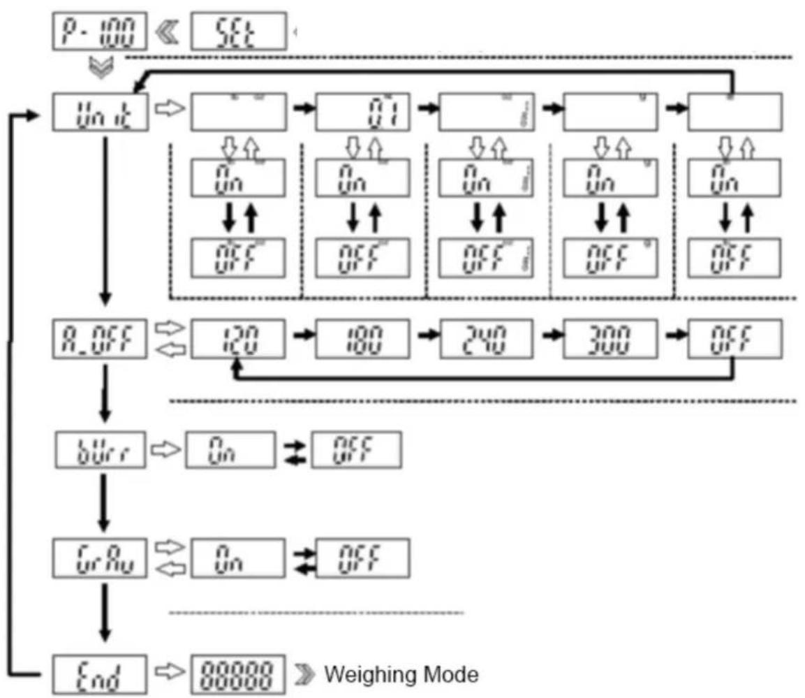
flowchart
graph TD
    A["P-100"] --> B["Set"]
    B --> C["Unit"]
    C --> D["Q1"]
    D --> E["Q2"]
    E --> F["Q3"]
    F --> G["Q4"]
    G --> H["Q5"]
    H --> I["Q6"]
    I --> J["Q7"]
    J --> K["Q8"]
    K --> L["Q9"]
    L --> M["Q10"]
    M --> N["Q11"]
    N --> O["Q12"]
    O --> P["Q13"]
    P --> Q["Q14"]
    Q --> R["Q15"]
    R --> S["Q16"]
    S --> T["Q17"]
    T --> U["Q18"]
    U --> V["Q19"]
    V --> W["Q20"]
    W --> X["Q21"]
    X --> Y["Q22"]
    Y --> Z["Q23"]
    Z --> AA["Q24"]
    AA --> AB["Q25"]
    AB --> AC["Q26"]
    AC --> AD["Q27"]
    AD --> AE["Q28"]
    AE --> AF["Q29"]
    AF --> AG["Q30"]
    AG --> AH["Q31"]
    AH --> AI["Q32"]
    AI --> AJ["Q33"]
    AJ --> AK["Q34"]
    AK --> AL["Q35"]
    AL --> AM["Q36"]
    AM --> AN["Q37"]
    AN --> AO["Q38"]
    AO --> AP["Q39"]
    AP --> AQ["Q40"]
    AQ --> AR["Q41"]
    AR --> AS["Q42"]
    AS --> AT["Q43"]
    AT --> AU["Q44"]
    AU --> AV["Q45"]
    AV --> AW["Q46"]
    AW --> AX["Q47"]
    AX --> AY["Q48"]
    AY --> AZ["Q49"]
    AZ --> BA["Q50"]
    BA --> BB["Q51"]
    BB --> BC["Q52"]
    BC --> BD["Q53"]
    BD --> BE["Q54"]
    BE --> BF["Q55"]
    BF --> BG["Q56"]
    BG --> BH["Q57"]
    BH --> BI["Q58"]
    BI --> BJ["Q59"]
    BJ --> BK["Q60"]
    BK --> BL["Q61"]
    BL --> BM["Q62"]
    BM --> BN["Q63"]
    BN --> BO["Q64"]
    BO --> BP["Q65"]
    BP --> BQ["End"]

    subgraph "Weighing Mode"
        direction TB
        C --> D
        D --> E
        E --> F
        F --> G
        G --> H
        H --> I
        I --> J
        J --> K
        K --> L
        L --> M
        M --> N
        N --> O
        O --> P
        P --> Q
        Q --> R
        R --> S
        S --> T
        T --> U
        U --> V
        V --> W
        W --> X
        X --> Y
        Y --> Z
        Z --> AB
        AB --> AB
        AB --> AC
        AC --> AD
        AD --> AE
        AE --> AF
        AF --> AG
        AG --> AH
        AH --> AI
        AI --> AJ
        AJ --> AK
        AK --> AL
        AL --> AM
        AM --> AJ
        AJ --> AN
        AN --> AO
        AO --> AP
        AP --> AQ
        AQ --> AR
        AR --> AS
        AS --> AT
        AT --> AU
        AU --> AV
        AV --> AW
        AW --> AX
        AX --> AY
        AY --> AZ
        AZ --> BA
        BA --> BB
        BB --> BC
        BC --> AD
        AD --> AE
        AE --> AF
        AF --> AG
        AG --> AH
        AH --> AI
        AI --> AJ
        AJ --> AK
        AK --> AL
        AL --> AM
        AM --> AN
        AN --> AO
        AO --> AP
        AP --> AQ
        AQ --> AR
        AR --> AS
        AS --> AT
        AT --> AU
        AU --> AV
        AV --> AW
        AW --> AX
        AX --> AY
        AY --> AZ
        AZ --> BA
        BA --> BB
        BB --> BC
        BC --> AD
        AD --> AE
        AE --> AF
        AF --> AG

    %% Legend labels are not present in the image. The diagram shows a hierarchical structure of the process. The structure is labeled with standard alphanumeric characters and mathematical notations. Text 'Weighing Mode' appears at the bottom right of the diagram. Bottom label 'End' at the bottom right contains the number '88888' with an arrow pointing right. Bottom label 'In' at the bottom left contains the number '88888'. Bottom label 'In' at the bottom center contains the number '88888'. Bottom label 'In' at the bottom center contains the number '88888'. Bottom label 'In' at the bottom left contains the number '88888'. Bottom label 'In' at the bottom center contains the number '88888'. Bottom label 'In' at the bottom center contains the number '88888'. Bottom label 'In' at the bottom left contains the number '88888'. Bottom label 'In' at the bottom center contains the number '88888'. Bottom label 'In'
10.5 Menu settings
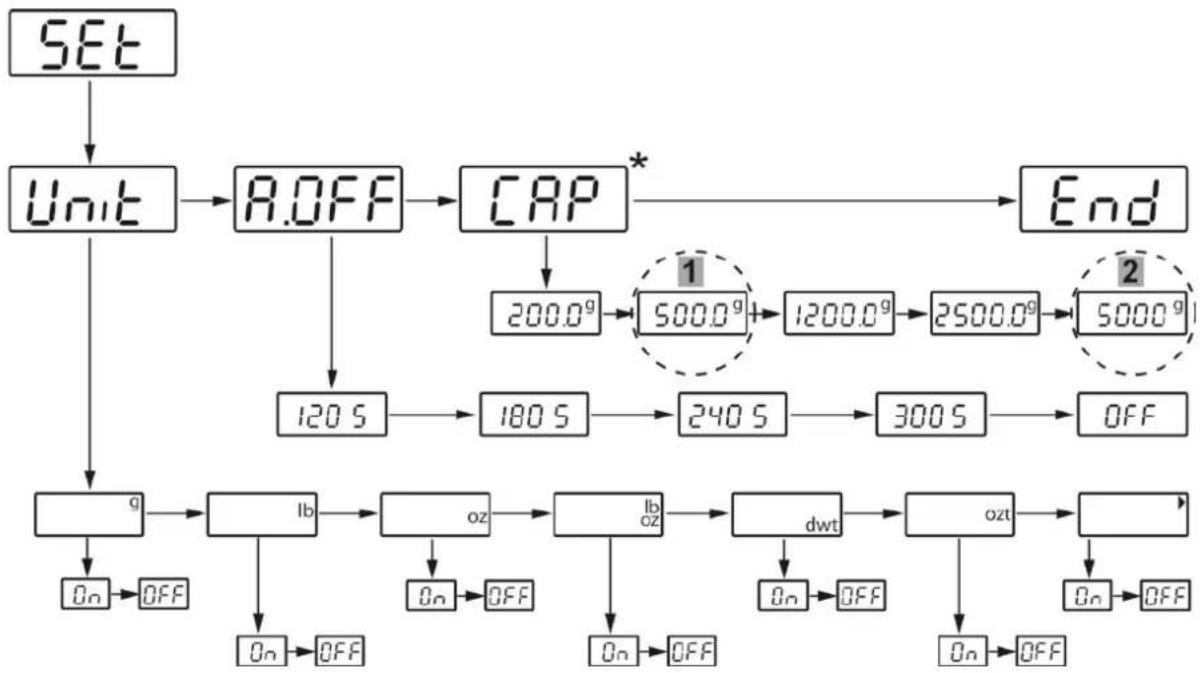
10.5.1 Setting weighing units
| Balance display Operation | |
 | FOB-S:In weighing mode, press and hold theTAREbutton for approx. 3 seconds.„SEt“, followed by „Unit“ is displayedFOB-NL:Switch off the balancePress and hold theON/OFFkey and simultaneously press theTAREkey 3 times and then release both keys. |
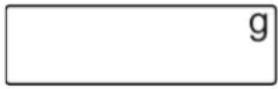 | Press theTAREkey again, the weighing unit "g" is displayed |
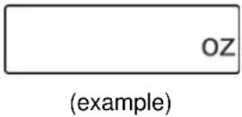 | Useunitto change to the desired unit |
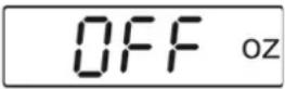 | Press theTAREkey, "OFF" is displayed |
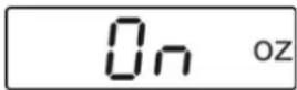 (example) (example) | Press theUNITkey to change to "On |
 (example) (example) | Press theTAREkey, the selected unit will be displayed thus being set. |
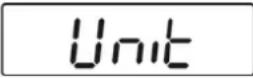 | Press the UNIT key until "Unit" is displayed |
 | Press the UNIT key, "A.Off" is displayed |
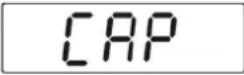 | Press the UNIT key, "CAP." is displayed |
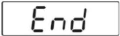 | Press the UNIT key, "End" is displayed |
 | Press the TARE key, to return to the weighing mode. |
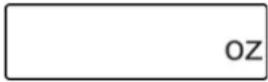
| Switch between the set units using the UNIT key |
| i | In order to switch off the units display, proceed as described above and set the selected unit to „Off“. |
10.5.2 Automatic switch-off function „AUTO OFF“ in stand-by mode
The balance offers the possibility of the automatic switch-off, when the balance is in stand-by mode. The switch-off time may be selected as follows:
Models FOB-S, FOB-NL:
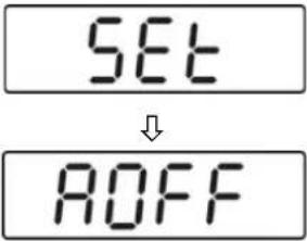
| Balance display Operation | |
 | FOB-S:In weighing mode, press and hold theTAREbutton for approx. 3 seconds.„SEt“, followed by „Unit“ is displayedFOB-NL:Switch off the balancePress and hold theON/OFFkey and simultaneously press theTAREkey 3 times and then release both keys. |
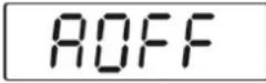
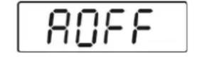
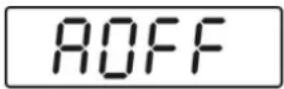 | Press theUNITkey, "AOFF" is displayed |
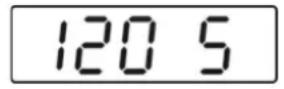 ò ò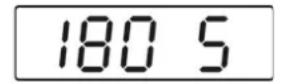 ò ò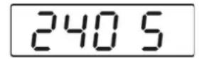 ò ò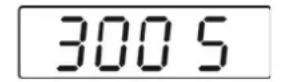 ò ò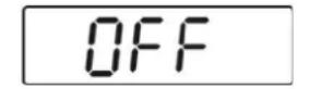 | Press theTARE-key, current setting appears.Press theUNITkey to select the desired setting:120s = Auto off after 120 seconds180s = Auto off after 180 seconds240s = Auto off after 240 seconds300s = Auto off after 300 secondsOFF = Auto off switched off |
 | Press theTAREkey to confirm your selection, "AOFF" is displayed |
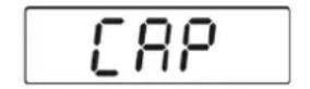 | Press theUNITkey, "CAP" is displayed |
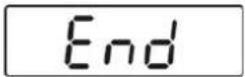 | • Press the UNIT key again, "End" is displayed |
 | • To return to weighing mode, press the TARE- key. The setting is saved. |
Models FOB-NS:
| Balance display Operation | |
 | In weighing mode, press and hold theTAREbutton for approx. 3 seconds.„SEt“, followed by „A.OFF“ is displayed |
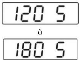 ò ò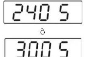 ò ò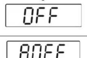 | Press theTARE-key, current setting appears.Press theUNITkey to select the desired setting:120s = Auto off after 120 seconds180s = Auto off after 180 seconds240s = Auto off after 240 seconds300s = Auto off after 300 secondsOFF = Auto off switched off |
| Press theTAREkey to confirm your selection,"AOFF" is displayed | |
 | Press theUNITkey again, "End" is displayed |
| To return to weighing mode, press theTARE-key.The setting is saved. |
| i | The auto-off function is only possible in battery operation.This function is deactivated during mains operation. |
11 Error reports
 | Battery empty | Insert new batteries or connect the balance to the power supply using the AC adapter. |
  | Overload - The weight on the weighing platform exceeds the capacity of the balance. | Reduce load |
  | Underload | Increase the load, if the error message remains, please contact your retailer |
 | Zero range when switching on | Check that the weighing pan is correctly seated |
 | Zero setting range exceeded at switch-on | Remove objects from the weighing pan |
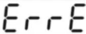 | Software error | Contact your retailer |
12 Servicing, maintenance, disposal
12.1 Cleaning
Before cleaning, please disconnect the appliance from the operating voltage.
→ Clean the stainless-steel parts with a soft cloth soaked with a cleaning agent suitable for stainless steel.
For stainless steel parts do not use any cleaning agents which contain sodium hydroxide solution, acetic, hydrochloric, sulphuric or citric acid.
Do not use metal brushes or cleaning sponges of steel wool, as this causes superficial corrosion.
Spilled weighing goods must be removed immediately.
12.2 Servicing, maintenance
The appliance may only be opened by trained service technicians who are authorized by KERN.
Before opening, disconnect from power supply.
12.3 Disposal
Disposal of packaging and appliance must be carried out by operator according to valid national or regional law of the location where the appliance is used.
13 Instant help
In case of an error in the program process, briefly turn off the balance and disconnect from power supply. The weighing process must then be restarted from the beginning.
Help:
Fault Possible cause
The displayed weight does not glow.
- The balance is not switched on.
- The mains supply connection has been interrupted (mains cable not plugged in/faulty).
• Power supply interrupted. - (Rechargeable) batteries are inserted incorrectly or empty
- No (rechargeable) batteries inserted.
The displayed weight is permanently changing
- Draught/air movement
- Table/floor vibrations
- Weighing pan has contact with other objects.
- Electromagnetic fields / static charging (choose different location/switch off interfering device if possible)
The weighing result is obviously incorrect
• The display of the balance is not at zero
- Adjustment is no longer correct.
• Great fluctuations in temperature.
• Warm-up time was ignored.
- Electromagnetic fields / static charging (choose different location/switch off interfering device if possible)
Should other error messages occur, switch balance off and then on again. If the error message remains inform manufacturer.

KERN FOB
Version 2.5 2021-11
KERN FOB-NS:
KERN FOB-NL:

KERN FOB-LM
KERN FOB :
Pos. Désignation
Modèles FOB-NS:
Modèles FOB-NL:
Modèles FOB-LM:
Modèles FOB:

natural_image
Two circular diagrams with concentric rings and intersecting lines, no text or symbols presenti
natural_image
Line drawing of a hand holding a small object on a device (no text or symbols)Exemple d'illustration KERN FOB-LM

natural_image
Diagram of a device's cable port with a red arrow pointing to a button (no text or symbols present)Exemple d'illustration KERN FOB
natural_image
Gray square object with a white circular arrow symbol on its surface (no text or labels)natural_image
Top-down view of a circular mechanical component with mounting holes and a central triangular feature (no text or symbols visible)natural_image
Close-up of a metallic industrial fan or pump component with four blades and central hub (no visible text or symbols)natural_image
Top-down view of a rectangular electronic device with mounting holes and a central internal component (no text or symbols visible)FOB-NL, FOB-LM
natural_image
Top-down view of a rectangular electronic device casing with mounting holes and internal components (no text or symbols visible)
flowchart
```mermaid
graph TD
    A["P-100"] --> B["Set"]
    B --> C["Unit"]
    C --> D["Q1"]
    D --> E["Q2"]
    E --> F["Q3"]
    F --> G["Q4"]
    G --> H["Q5"]
    H --> I["Q6"]
    I --> J["Q7"]
    J --> K["Q8"]
    K --> L["Q9"]
    L --> M["Q10"]
    M --> N["Q11"]
    N --> O["Q12"]
    O --> P["Q13"]
    P --> Q["Q14"]
    Q --> R["Q15"]
    R --> S["Q16"]
    S --> T["Q17"]
    T --> U["Q18"]
    U --> V["Q19"]
    V --> W["Q20"]
    W --> X["Q21"]
    X --> Y["Q22"]
    Y --> Z["Q23"]
    Z --> AA["Q24"]
    AA --> AB["Q25"]
    AB --> AC["Q26"]
    AC --> AD["Q27"]
    AD --> AE["Q28"]
    AE --> AF["Q29"]
    AF --> AG["Q30"]
    AG --> AH["Q31"]
    AH --> AI["Q32"]
    AI --> AJ["Q33"]
    AJ --> AK["Q34"]
    AK --> AL["Q35"]
    AL --> AM["Q36"]
    AM --> AN["Q37"]
    AN --> AO["Q38"]
    AO --> AP["Q39"]
    AP --> AQ["Q40"]
    AQ --> AR["Q41"]
    AR --> AS["Q42"]
    AS --> AT["Q43"]
    AT --> AU["Q44"]
    AU --> AV["Q45"]
    AV --> AW["Q46"]
    AW --> AX["Q47"]
    AX --> AY["Q48"]
    AY --> AZ["Q49"]
    AZ --> BA["Q50"]
    BA --> BB["Q51"]
    BB --> BC["Q52"]
    BC --> BD["Q53"]
    BD --> BE["Q54"]
    BE --> BF["Q55"]
    BF --> BG["Q56"]
    BG --> BH["Q57"]
    BH --> BI["Q58"]
    BI --> BJ["Q59"]
    BJ --> BK["Q60"]
    BK --> BL["Q61"]
    BL --> BM["Q62"]
    BM --> BN["Q63"]
    BN --> BO["Q64"]
    BO --> BP["Q65"]
    BP --> BQ["End"]

    subgraph "Weighing Mode"
        direction TB
        C --> D
        D --> E
        E --> F
        F --> G
        G --> H
        H --> I
        I --> J
        J --> K
        K --> L
        L --> M
        M --> N
        N --> O
        O --> P
        P --> Q
        Q --> R
        R --> S
        S --> T
        T --> U
        U --> V
        V --> W
        W --> X
        X --> Y
        Y --> Z
        Z --> AB
        AB --> AB
        AB --> AC
        AC --> AD
        AD --> AE
        AE --> AF
        AF --> AG
        AG --> AH
        AH --> AI
        AI --> AJ
        AJ --> AK
        AK --> AL
        AL --> AM
        AM --> AJ
        AJ --> AN
        AN --> AO
        AO --> AP
        AP --> AQ
        AQ --> AR
        AR --> AS
        AS --> AT
        AT --> AU
        AU --> AV
        AV --> AW
        AW --> AX
        AX --> AY
        AY --> AZ
        AZ --> BA
        BA --> BB
        BB --> BC
        BC --> AD
        AD --> AE
        AE --> AF
        AF --> AG
        AG --> AH
        AH --> AI
        AI --> AJ
        AJ --> AK
        AK --> AL
        AL --> AM
        AM --> AN
        AN --> AO
        AO --> AP
        AP --> AQ
        AQ --> AR
        AR --> AS
        AS --> AT
        AT --> AU
        AU --> AV
        AV --> AW
        AW --> AX
        AX --> AY
        AY --> AZ
        AZ --> BA
        BA --> BB
        BB --> BC
        BC --> AD
        AD --> AE
        AE --> AF
        AF --> AG

    %% Legend labels are not present in the image. The diagram shows a hierarchical structure of signal processing blocks and their corresponding components. The structure is labeled with the same block names and the corresponding component names. The note "Weighing Mode" indicates the structural type of the data. The arrows indicate the transformation from left to right, indicating the progression of the input signals through the processing blocks. The output is estimated based on the input signal values. The output is estimated based on the output signal values. The output is estimated based on the output signal values. The output is estimated based on the output signal values. The output is estimated based on the output signal values. The output is estimated based on the output signal values. The output is estimated based on the output signal values. The output is estimated based on the output signal values. The output is estimated based on the output signal values. The output is estimated based on the output signal values. The output is estimated based on the output signals. The output is estimated based on the output signals value. The output is estimated based on the output signal value value. The output is estimated based on the output signal value value. The output is estimated based on the output signal value value. The output is estimated based on the output signal value value. The output is estimated based on the output signal value value. The output is estimated based on the output signal value value. The output is estimated based on the output signal value value. The output is estimated based on the output signal value value. The output is estimated based on the output signal value value. The outputs are estimated based on the output signal values. The outputs are estimated based on the output signal values. The outputs are estimated based on the output signal values. The outputs are estimated based on the output signal values. The outputs are estimated based on the output signal values. The outputs are estimated based on the output signal values. The outputs are estimated based on the output signal values. The outputs are estimated based on the output signal values. The outputs are estimated based on the output signal values. The outputs are estimated based on the output signal values.
The outputs are estimated based on the output signal values.
The outputs are estimated based on the output signal values.
The outputs are estimated based on the output signal values.
The outputs are estimated based on the output signal values.
The outputs are estimated based on the output signal values.
The outputs are estimated based on the output signal values.
The outputs are estimated based on the output signal values.
The outputs are estimated based on the output signal values.
The outputs are estimated based on the output signal values.
The output is estimated based on the output signal values.
The outputs are estimated based on the output signal values.
The outputs are estimated based on the output signal values.
The outputs are estimated based on the output signal values.
The outputs are estimated based on the output signal values.
The outputs are estimated based on the output signal values.
The outputs are estimated based on the output signal values.
The outputs are estimated based on the output signal values.
The outputs are estimated based on the output signal values.
The outputs areEstimated by arrowheads.

All bars represent a single bar, with one bar labeled 'Off' pointing downward from left to right, one bar labeled 'R', one bar labeled 'O', one bar labeled 'U', one bar labeled 'V', one bar labeled 'W', one bar labeled 'X', one bar labeled 'Y', one bar labeled 'Z', one bar labeled 'A', one bar labeled 'B', one bar labeled 'C', one bar labeled 'D', one bar labeled 'E', one bar labeled 'F', one bar labeled 'G', one bar labeled 'H', one bar labeled 'I', one bar labeled 'J', one bar labeled 'K', one bar labeled 'L', one bar labeled 'M', one bar labeled 'N', one bar labeled 'O', one bar labeled 'P'.