
DSD 250 - Grinder METABO - Free user manual and instructions
Find the device manual for free DSD 250 METABO in PDF.

User questions about DSD 250 METABO
0 question about this device. Answer the ones you know or ask your own.
Ask a new question about this device
Download the instructions for your Grinder in PDF format for free! Find your manual DSD 250 - METABO and take your electronic device back in hand. On this page are published all the documents necessary for the use of your device. DSD 250 by METABO.
USER MANUAL DSD 250 METABO
natural_image
Three metalworking machines labeled 'metabo' with no visible text or symbols on the machines themselves.
text_image
Technical diagram showing mechanical assembly steps with numbered annotations and a close-up detail view of a component.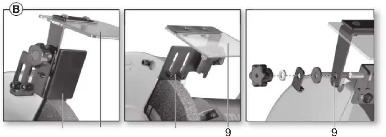
natural_image
Three-panel technical diagram showing mechanical assembly steps with labeled parts (B, 9), no readable text or symbols present.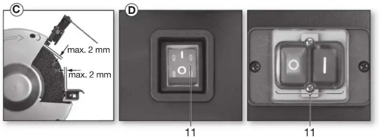
text_image
C max. 2 mm max. 2 mm D 11 11
text_image
BS 175 8 1 2 1 3 1 metabo MS 175 15 16 6
text_image
E II metabo 50 1/8 I IIITNS 175

text_image
175 17 4 18 19 metabo TNS 175| BS 175*1) Serial Number: 01750.. | DS 125*1) Serial Number: 19125.. | DS 150*1) Serial Number: 19150.. | DS 175*1) Serial Number: 19175.. | DS 200*1) Serial Number: 19200.. | DSD 200*1) Serial Number: 19201.. | DSD 250*1) Serial Number: 19250.. | TNS 175*1) Serial Number: 11750.. | ||
| D_max × B | mm(in) | 175x25(7x1) | 125x20(5 x3/4) | 150x20(6 x3/4) | 175x25(7x1) | 200x25(8x1) | 200x25(8x1) | 250x40(10 x 11/2) | 175x25(7x1) |
| d mm (in) | 32(11/4) | 203/4) | 203/4) | 32(11/4) | 32(11/4) | 32(11/4) | 51(2) | 32(11/4) | |
| D_N, max × B | mm(in) | - | - | - | - | - | 200x40(8 x 11/2) | ||
| d_N | mm (in) - | - | - | - | - | - | 203/4) | ||
| A | mm(in) | 1020x50(401/6 x 2) | - | - | - | - | |||
| n_0 | min-1(rpm) | 2980 2980 2980 2980 2980 2980 2980 2980 2980 2980 2980 2980 2980 2980 2980 2980 2980 2980 2980 2980 2980 | |||||||
| v_0 | m | / | s | 18 | - | - | - | ||
| P_1 | W | 500 | 200 | 350 | 500 | 600 | 750 | 650 | 500 |
| P_2 | W | 310 | 130 | 200 | 310 | 420 | 550 | 490 | 310 |
| M_K | Nm | 2,3 | 0,9 | 1,1 | 2,3 | 2,6 | 7,2 | 10 | 2,3 |
| m | kg(lbs) | 14,9(32.8) | 7,5(16.5) | 9,5(21) | 14,9(32.8) | 16,6(36.6) | 17,2(37.9) | 33,8(74.5) | 15,2(33.5) |
| L_pA/K_pA | dB(A) | 71 / 3 | 52 / 3 | 58 / 3 | 61 / 3 | 70 / 3 | 72 / 3 | 57 / 3 | 61 / 3 |
| L_WA/K_pA | dB(A) | 88 / 3 | 69 / 3 | 70 / 3 | 69 / 3 | 76 / 3 | 76 / 3 | 72 / 3 | 69 / 3 |
text_image
Dmax d B
*2) 2014/30/EU, 2006/42/EC, 2011/65/EU
*3) EN 61029-1:2009+A11:2010, EN 61029-2-4:2011, EN 50581:2012
DSD 250: EN ISO 16089:2015, EN 60034-1:2010, EN 60204:2006+A1:2009, EN 50581:2012

2017-02-15, Bernd Fleischmann
natural_image
Close-up of hands using a power tool on a cutting board (no visible text or symbols)$$ m = G e w i c h 1 $$
Original instructions
1. Declaration of Conformity
We declare under our sole responsibility: These bench grinders, identified by type and serial number *1), comply with all relevant requirements of the directives *2) and standards *3). Technical file at *4) - see page 4.
2. Specified Use
The grinders are suitable for dry, peripheral grinding of metals - only in dry rooms and for occasional grinding. The workpiece is guided by hand.
The belt sander (BS 175) is also suitable for dry sanding of metal and derived wood products.
The dry/wet grinder (TNS 175) can also be used for sharpening knives, chisels, shears and other cutting tools, in addition to processing small metal workpieces on the wet grindstone.
The grinders are not suitable for grinding aluminium, magnesium or other materials associated with a risk of fire or explosion.
Not suitable for polishing.
Not suitable for grinding materials that could produce dust harmful to health.
The user bears sole responsibility for any damage caused by improper use.
Generally accepted accident prevention regulations and the enclosed safety information must be observed.
3. General Safety Instructions

WARNING – Reading the operating instructions will reduce the risk of injury.

WARNING Read all safety warnings and instructions. Failure to follow all safety
warnings and instructions may result in electric shock, fire and/or serious injury.
Keep all safety instructions and information for future reference.
Before using the power tool, carefully read through and familiarise yourself with all the enclosed safety information and the Operating Instructions. Keep all enclosed documentation for future reference, and pass on your power tool only together with this documentation.
4. Special Safety Instructions

For your own protection and for the protection of your power tool, pay attention to all parts of the text that are marked with this symbol!
The grinding wheel must match the machine. Observe the maximum grinding wheel diameter and thickness. The hole diameter must match the back
flange without play. Do not use adapters or reducers.
Do not drill grinding wheels.
Do not trim grinding wheels.
The grinding wheels must be fitted perfectly and turn freely.
Damaged, eccentric or vibrating grinding wheels must not be used.
When clamping the grinding wheels, only the flanges included in the delivery must be used. The intermediate layers between flange and grinding tool must be made of elastic materials, e.g. soft cardboard etc.
Protect grinding wheels against shocks, bumps and grease.
Grinding discs must be stored and handled with care in accordance with the manufacturer's instructions.
Do not touch the rotating grinding wheel!
Only work when the safety cover (1) and sanding belt cover (16) are fitted.
Swivel the eye preservers (9) downwards before grinding.
Use the perimeter (not the sides) of the grinding wheels for grinding.
Do not reduce the speed of the grinding wheel by pressing on the sides.
The workpiece to be processed must be large enough, or small enough, to be held safely with both hands.
Only work when the grinding wheels are fitted to minimise the risk of coming into contact with the rotating spindle.
High temperatures can result after long-term operation.

Always wear eye goggles, hearing protection and protective gloves. Use other available personal protective equipment, e.g. suitable
protective work clothing. Ensure that sparks produced during work do not constitute a risk to the user or other personnel and are not able to ignite inflammable substances. Endangered areas must be protected with flame-resistant covers. Make sure that fire-risk areas are always provided with suitable fire extinguishers.
The workpiece can become hot during grinding.
Do not allow water within the vicinity of electric machine parts or close to people in the working area.
If a grinding material blockage occurs, switch off the grinder immediately, allow the motor to stop and unplug the grinder. Identify the cause and remove the blockage.
Clean, check and perform maintenance work on the machine and guard devices regularly. Regularly
clean the inside of the grinding wheels and belt grinder housing. The grinding wheels and sanding belt must be able to rotate freely within the housing.
Unplug when the grinder is not in use, before making any adjustments or carrying out modifications, repairs or maintenance.
Regularly check the power cable on the grinder and have it repaired by an approved expert if damaged.
Regularly check extension cables and replace if damaged.
Check the grinder for possible damage: Before using the grinder, protective devices or slightly damaged components must be carefully checked to ensure they are operating perfectly and as intended. Check that moving parts are in perfect working order and do not jam and check whether parts are damaged. All parts must be correctly installed and fulfil all conditions necessary to ensure perfect operation of the grinder. Damaged protective devices and parts must be repaired or replaced according to specifications by an authorised specialist workshop.
Reduce dust exposure:

Particles generated when working with this machine may contain substances that can
cause cancer, allergic reactions, respiratory diseases, birth defects or other propagation defects. Some of these substances include: Lead (in paint containing lead), mineral dust (from bricks, concrete etc.), additives used for wood treatment (chromate, wood preservatives), some wood types (such as oak or beech dust), metals, asbestos. The risk depends on for how long the user or nearby persons are exposed to the substance.
This dust must not be allowed to enter your body. Do the following to reduce exposure to these substances: Ensure good ventilation of the workplace and wear appropriate protective equipment, such as respirators able to filter microscopically small particles.
Observe the relevant guidelines for your material, staff, application and place of application (e.g. occupational health and safety regulations, disposal).
Collect the generated particles at the source, avoid deposits in the surrounding area.
Use suitable accessories for special work (see chapter 9.), thus less particles enter the environment in an uncontrolled manner.
Use a suitable extraction unit.
Reduce dust exposure with the following measures:
- Use an extraction unit and/or air purifiers
- Ensure good ventilation of the workplace and keep clean using a vacuum cleaner Sweeping or blowing stirs up dust
- Vacuum or wash the protective clothing Do not blow, beat or brush
5. Overview
See page 2 and page 3.
1 Safety cover
2 A d j u s t i n g n u t
3 Clamping flange
4 Grinding wheel
5 Back flange
6 Dust extraction connection
7 Safety cover
8 Workpiece support
9 Eye preservers
10 Spark deflector
11 Switch (on/off)
12 Lever (sanding belt replacement) *
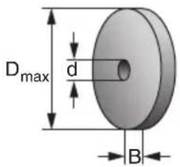
14 Rotary knob for adjusting the belt run *
16 Sanding belt cover *
18 Water container *
19 Rubber stopper *
13 Screws for securing the sanding belt cover *
15 Arrow (direction of circulation of sanding belt)*
17 Screws for securing the water container *
* depending on equipment/not in scope of delivery
6. Initial Operation
6.1 Power supply
Before plugging in, check that the rated mains voltage and mains frequency, as stated on the rating label, match with your power supply.
The grinder complies with protection class I and must therefore only be connected to sockets earthed according to specifications.
DSD 200, DSD 250 (three-phase version):
Ensure that the grinding wheels have the correct direction of rotation (the correct direction of rotation is indicated by an arrow on the side safety guards). If a grinding wheel is rotating in the wrong direction:
Unplug the grinder. The plug comprises of two phase conducting pins that are mounted on a rotating socket (phase changing switch). Use a Phillips screwdriver to rotate this socket.
6.2 Installing workpiece support
Install workpiece support (8) as shown in illustrations A, page 2.
6.3 Fitting spark deflector and eye preservers
Install the spark deflector (10) and eye preservers (9) as shown in illustrations B, page 2.
6.4 Installing machine safely
Place the machine on a stable workbench. Ensure that the machine is securely seated.
The machine can also be bolted down (screws not included in the scope of delivery). To do this, fasten the securing screws through the holes in the rubber feet.
If a stand or wall bracket is used (see Accessories chapter): bolt down the machine.
6.5 Dust extraction connection (depending on equipment)
If your machine is not equipped with a dust extraction connection (6), fit an extraction device that
ENGLISHen
is suitable for double-wheeled bench grinders. Inner diameter of extraction connection piece: 35 mm. Before switching on the machine, ensure that the extraction device is connected and being used correctly.
6.6 Test run
Check the grinding wheels before initial use.

Test run
A test run of approx. 5 min without load must be carried out before initial use. All persons must stay clear of the danger zone when this is performed.
7. Use
7.1 Adjusting the workpiece support
Adjust the workpiece supports (8) frequently to compensate for wear of the grinding wheels (4).
The distance between the workpiece support and grinding material must be as small as possible and never greater than 2 mm (see illustration C, page 2).
If the grinding wheel is so badly worn that the maximum distance of 2 mm can no longer be maintained, the grinding wheel must be replaced.
7.2 Adjusting the spark deflector
Adjust the spark deflectors (10) regularly to compensate for wear on the grinding wheels (4).
Release the 2 screws on the spark deflector and shift the spark deflector.
The distance between the spark deflector and grinding wheel must be as small as possible and never greater than 2 mm (see illustration C, page 2).
If the grinding wheel is so badly worn that the maximum distance of 2 mm can no longer be maintained, the grinding wheel must be replaced.
7.3 Switching On and Off
Press the switch (11) (see illustrations D, page 2).
$$ \begin{array}{c c c c c c c c c c} \mathbf {I} = & \text {S} & \text {w} & \text {i} & \text {t} & \text {c} & \text {h} & \text {o} & \text {n} \ \mathbf {0} = & \text {S} & \text {w} & \text {i} & \text {t} & \text {c} & \text {h} & \text {o} & \text {f} & \text {f} \end{array} $$
DS 125, DS 150: Avoid inadvertent starts: always switch the grinder off when the plug is removed from the mains socket or if there has been a power cut.
Restart protection (not in DS 125, DS 150):
When power is restored after a power failure, the machine - which is still switched on - will not start automatically for safety reasons. Switch machine on and off again.
7.4 Dry grinding, belt sanding
- Stand in front of the grinder.
- Holding the workpiece with both hands, place the workpiece on the workpiece supports (8) and gently press it against the dry grinding wheel/sanding belt. For optimum grinding/sanding results, move the workpiece gently to and fro. This also helps to distribute wear evenly on the grinding material.
7.5 Wet grinding (TNS 175 only)

Only use the wet grinding wheel for grinding when there is water in the water container.
(18). Roughly 1/3 of the wet grinding wheel should be immersed in water. grinding results may impaired if the water level is either too low or too high.
- Stand to the left of the grinder, in front of the wet grinding wheel.
- Holding the workpiece with both hands, lower it onto the wet grinding wheel. You can also support the workpiece on the levels on the water container (18) and then lower the workpiece onto the wet grinding wheel.
7.6 Adjusting the belt run (BS 175 only)

Unplug. Rotate the sanding belt manually. Use the rotary knob (14) to adjust the sanding belt at it runs centrally on the sanding belt roller.
text_image
147.7 Setting the angle of the belt sanding arm (only BS 175) (see page 3 fig. E)
- Loosen the screw at the belt sanding arm
- Put the belt sanding arm in the desired position
- Tighten again the screw at the belt sanding arm
8. Maintenance, cleaning
Clean, check and perform maintenance work on the machine and guard devices regularly. Regularly clean the inside of the grinding wheels and belt grinder housing. The grinding wheels and sanding belt must be able to rotate freely within the housing.

Disconnect the mains plug before starting any setting, cleaning, maintenance or repair work.
8.1 Grinding wheel change

Use only original Metabo grinding wheels.

The permissible rotational speed specified on the grinding wheel must be equal to or greater the maximum idling speed specified on the ification plate of the machine.

Grinding wheel check: suspend the grinding wheel on a thread.
Knock lightly with a piece of hard wood. You will hear a clear tone if the grinding wheel is in perfect condition. If you hear a clattering, dull or hollow sound, the grinding wheel is damaged.

Do not use damaged grinding wheels.

Test run
A test run of approx. 5 min without load must be carried out after the grinding wheel has been
changed. All persons must stay clear of the danger zone when this is performed.
Dry grinding wheel:
- Release the screws on the safety guard cover (1), twist and remove the cover (1) (bayonet catch).
- Hold the grinding wheel (4) firmly in position as shown. Caution! Risk of injury! Wear protective gloves!
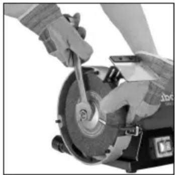
natural_image
Close-up of a person using a power tool on a mechanical grinding machine (no visible text or symbols)- Remove adjusting nut (2) with open-ended spanner.
Caution! Left-hand thread on left machine side, i.e. to release the adjusting nut (2) on the left machine side, turn clockwise! - Remove clamping flange (3) and grinding wheel (4).
- Secure new grinding wheel (4) in the reverse order.
- Remount the safety cover (1). Tighten screws.
- Adjust the spark deflector (10) and workpiece support (8) as described in chapter 7.2 and 7.1.
Replacing the wet grinding wheel (TNS 175 only):
- Empty the water container (18): hold a collecting pan under the container and remove the rubber stopper (19). Re-insert the rubber stopper.
- Loosen the 3 screws (17) adequately and lower the water container.
- Using one hand, hold the grinding wheel (4) secure. Caution! Risk of injury! Wear protective gloves!
- Remove adjusting nut with open-ended spanner. (Loosen by turning anti-clockwise).
- Remove clamping flange and grinding wheel (4).
- Secure new grinding wheel (4) in the reverse order.
- Replace the water container (18). (17) Tighten screws. Fill the water container with the correct amount of water (see chapter 7.5)
8.2 Replacing the sanding belt (BS 175 only)
Remove the side sanding belt cover (16): release the 2 screws (13), slide the sanding belt cover (16) (bayonet catch) and remove.
Swivel out lever (12) as far as it will go. This relieves sanding belt tension and it can now be removed from the rollers.
Place the new sanding belt on the rollers so that its direction of circulation (arrows on the inside of the sanding belt) matches the arrow (15) (16) on the side sanding belt cover.
Return the lever (12) to the original position to tension the sanding belt.
Place the side sanding belt cover (16) on the 2 screws (13) and slide (bayonet catch). Tighten the two screws.
Adjust the belt run (see chapter 7.6).
For sanding belts, see Accessories chapter 9..
8.3 Water container (TNS 175 only)
Regularly replace the water in the water container (18). To do this, hold a collecting pan under the container and remove the rubber stopper (19).
Dismantle the water container for cleaning purposes, as described in chapter 8.1. Use water and a brush (no metal bristles) to clean the inside of the container.
9. Accessories
Use only genuine Metabo accessories.
If you need any accessories, check with your dealer.
For dealers to select the correct accessory, they need to know the exact model designation of your power tool.
A Grinding wheels .... Order No.:
D= 125 mm: 36P: ....0900025181 60 N: ....0900025190
D= 150 mm: 36 P: ....6.30632 60 N: ....6.30633
D=175 mm: 36P:....6.30657 60 N:....6.30656
D=200 mm: 36P:....6.30784 60 N:....6.30785
D=250 mm: 36 P:....6.30636 60 N:....6.30637
Wet grinding wheel D= 200 mm: ....0900025653
B S t a n d Order No.: 6.23867
C Wall bracket Order no.: 6.23862
DSanding belts
3 x P 40 0900025777
3 x P 60 0900025688
3 x P 80 0900025696
3 x P 100 0900025785
3 x P 120 0900025700
3 x P 180 0900025807
3 x P 240 0900025823
3 x P 400 0900025840
For a complete range of accessories, see www.metabo.com or the main catalogue.
10. Repairs
Repairs to electrical tools must be carried out by qualified electricians ONLY!
ENGLISHen
Contact your local Metabo representative if you have Metabo power tools requiring repairs. For addresses see www.metabo.com.
You can download a list of spare parts from www.metabo.com.
11. Environmental Protection
Metabo's packaging can be 100% recycled.
Scrap power tools and accessories contain large amounts of valuable resources and plastics that can be recycled.
These instructions are printed on chlorine-free bleached paper.

Only for EU countries: Never dispose of power tools in your household waste! In accordance with European Guideline 2002/
96/EC on used electronic and electric equipment and its implementation in national legal systems, used power tools must be collected separately and handed in for environmentally compatible recycling.
12. Technical Specifications
Explanatory notes on the specifications on page 4. Changes due to technological progress reserved.
D_max = maximum diameter of the grinding wheel
D_N,max =maximum diameter of the wet grinding wheel
d = Hole diameter of the grinding wheel
d N = Hole diameter of the wet grinding wheel
B = Thickness of the grinding wheel
A = Sanding belt (length x width)
n_0 =Idle speed
v_0 =Belt speed in idling
P_1 =Nominal power input
P_2 =Power output
M_K = Breakdown torque
m = W e i g h t
A-effective perceived sound levels:
L_pA =Sound pressure level
L_WA = Acoustic power level
L_pAl =Emission sound pressure level
K_^p = Uncertainty (sound level)
During operation the noise level can exceed 80 dB(A).

Wear ear protectors!
Measured values determined in conformity with EN 61029.
The technical specifications quoted are subject to tolerances (in compliance with the relevant valid standards).
Notice originale
natural_image
Close-up of hands using a power cutter on a cutting machine (no visible text or symbols)natural_image
Close-up of hands using a power tool to work on a metal cutting machine (no visible text or symbols)natural_image
Close-up of hands using a power tool on a cutting board (no visible text or symbols)natural_image
Close-up of hands using a power tool to cut a circular saw (no visible text or symbols)11 Interruptor Liga/Desliga
natural_image
Close-up of hands using a power tool on a workbench (no visible text or symbols)natural_image
Close-up of hands using a power tool to work on a mechanical grinding machine (no visible text or symbols)natural_image
Close-up of hands using a power tool to work on a mechanical grinding machine (no visible text or symbols)L_pA =äänenpainetaso
L_WA =äänentehotaso
natural_image
Close-up of hands using a power tool to work on a mechanical grinding machine (no visible text or symbols)natural_image
Close-up of a person using a power tool on a mechanical grinding machine (no visible text or symbols)natural_image
Close-up of hands using a power tool to cut a circular saw (no visible text or symbols)natural_image
Close-up of hands using a power tool to cut a circular saw (no visible text or symbols)natural_image
Close-up of hands using a power tool to cut a circular saw (no visible text or symbols)natural_image
Close-up of hands using a power tool to cut a circular saw (no visible text or symbols)"Metabo Powertools (China) Co. Ltd."
Bldg. 7, 3585 San Lu Road,
Pujiang Industrial Park, Min Hang District, Китай
Импортер в России:


