Flex-Force 51833T - Grass trimmer TORO - Free user manual and instructions
Find the device manual for free Flex-Force 51833T TORO in PDF.

| Brand | Toro |
| Model | Flex-Force 51833T |
| Product type | Cordless string trimmer |
| Power source | Lithium-ion battery 60 V max (54 V nominal) |
| Battery capacity | 2.0 Ah, 108 Wh |
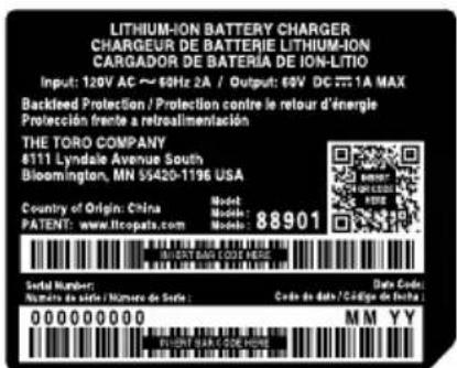
| Charger type | 60 V lithium-ion charger, input 120 V AC, 60 Hz |
| Blade length | 203 mm (8 in) |
| No-load speed | 7000 rpm |
| Weight (without battery) | 4.7 kg |
| Cutting depth adjustment | Yes, by wing nut |
| Auxiliary handle | Yes, adjustable |
| Folding handle | Yes |
| Safety system | Trigger release stop, battery lock |
| Charging temperature | 5°C to 40°C |
| Operating temperature | 0°C to 49°C |
| Country of origin | China |
| Package contents | String trimmer, 2.0 Ah battery, charger, Allen key, auxiliary handle, adjustment tool, manual |
| Maintenance | Cleaning, blade replacement, wheel replacement, skid plate replacement |
Frequently Asked Questions - Flex-Force 51833T TORO
User questions about Flex-Force 51833T TORO
0 question about this device. Answer the ones you know or ask your own.
Ask a new question about this device
Download the instructions for your Grass trimmer in PDF format for free! Find your manual Flex-Force 51833T - TORO and take your electronic device back in hand. On this page are published all the documents necessary for the use of your device. Flex-Force 51833T by TORO.
USER MANUAL Flex-Force 51833T TORO
Model No. 51833 —Serial No. 325000000 and Up Model No. 51833T —Serial No. 325000001 and Up
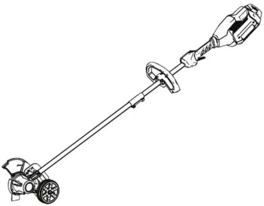
natural_image
Line drawing of a manual power tool with a lever and handle (no text or symbols)
For assistance, please see www .T oro.com/support for instructional resources or contact your Authorized Service Dealer before returning this product.
W ARNING
CALIFORNIA
Proposition 65 W arning
The
known
other
Use
known
power
to
the
reproductive
of
this
to
cord
the
State
product
[Non-Text]
State
or
on
this
of
harm.
may
of
| C:
reprc
Introduction
| This grass outdoors. These lithium-ion intended | edger around battery use | is it is battery could | intended the designed packs | edge are chargers.prove | to of to are | be drivew use designed |
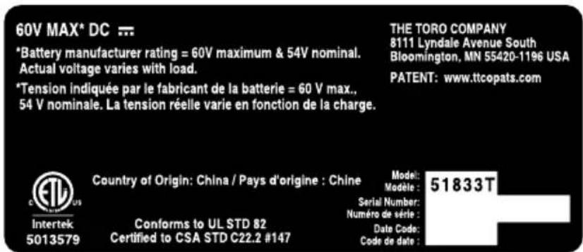
Model
51833T
does
not
includ
Read
your
responsible
this
product
information
properly
for
operating
carefully
and
to
the
V isit
accessory
WWW
.T oro.com
information,
for
product
help
©
2025—The
T oro®
Company
81
1 1
L yndale
A
venueOriginal
(EN)
South
Bloomington,
55420
Register
www
MN
.T
Printed
All oro.com. Rights

* 3 4 Reserved 3 0 7 *
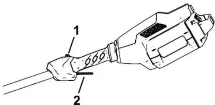
Whenever you need service, genuine the manufacturer parts, or addition information, contact an Authorized Service Dealer or the manufacturer Customer Service and have ready . Figure 1 identifies the the product. W rite the numbers
Important: the serial number with your mobile (if other product information.
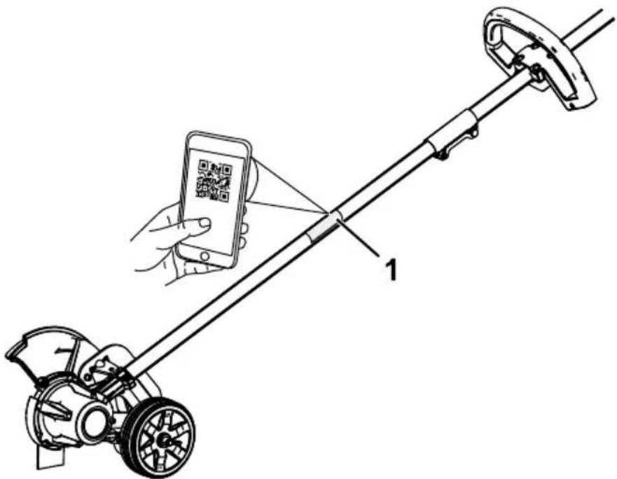
Figure 1
g428616
- Model
and
serial
number
location
Model No.
Serial No.
Safety-Alert Symbol
The safety-alert symbol (Figure 2) shown in this manual and on the machine identifies important prevent accidents.

Figure
Safety-alert
2
symbol
g000502
The safety-alert unsafe actions W WARNING, or symbol appears or situations CAUTION
DANGER indicates an imminently avoided, will result in death
W ARNING indicates a potentially avoided, could result in death
CAUTION may result indicates in minor a potentially or moderate This manual uses two other attention to special mechanical information worthy of special
Safety
IMPORT ANT SAFETY INSTRUCTIONS
⚠️ W ARNING
When using electric gardening tools, always read and follow basic safety warnings and instructions to reduce the risk of fire, electric shock, and
Read
All
Instructions
I. T raining
- The operator of the tool is occurring to others or their
- Do not allow children to us battery charger; local regulations
- Do not allow children or ur device. Allow only people the instructions, and physically device.
- Before using the tool, battery instructions and cautionary
- Become pack, and familiar with the battery charger
II. Preparation
- Keep bystanders and children
- Use and only attachments the battery may pack increase
- Plugging cause a fire other than plug the battery electric 120 adapter V. For attachment outlet if needed.
-
Do not use a damaged or which may exhibit unpredictable explosion, or risk of injury.
-
If the supply cord to the battery charger is damaged, contact an Authorized Service Dealer to replace it.
-
Charge the battery pack T oro. A charger suitable for of fire when used with another
-
Charge the battery pack
-
Follow outside all charging instructions of the temperature Otherwise, you may damage of fire.
-
Do not operate the tool with devices in place and functioning
-
Dress long pants; substantial, hearing protection. or loose jewelry that can get mask in dusty operating ear slip-1 can get con
III. Operation
- A void dangerous environments—Do damp or wet locations.
- Use the proper tool for your other an its intended use co bystanders.
- Prevent unintentional starting position before connecting tool with yo do not carry the switch in the yo tool with the O
- Operate the tool only in da
- If the tool strikes an object the tool, wait for all moving before examining the tool before resuming operation
- Remove the battery pack accessories.
- Keep your hands and feet parts.
-
Shut of f the tool, remove for all movement to stop before storing the tool.
-
Remove the battery pack from the tool whenever you leave it unattended.
-
Do not force the tool—Allow the rate for which it was design
- Do not overreach—Keep especially on slopes. W alk,
- Stay alert—W atch what operating the tool. Do not influence of alcohol or drugs.
- Ensure that the ventilation
- Under contact. water ejected
abusive If you . If the liquid from the conditions, accidentally contacts battery
conditions, c
pack
15. Do not expose to fire a battery exposure explosion. or temperature
16. CAUTION—A explosion, or chemical mistreated burn.
- Do not disassemble the - Replace the battery pack using another type of battery injury.
- Keep battery packs out c packaging until you are re
IV. Maintenance and Storage
- Maintain the tool with care—K performance and to reduce for lubricating and and changing and free from and oil and grease.
- When such as the paper battery clips, pack is connection may cause from burns 1 terminal or a fire.
- Keep your hands and feet
-
Shut of f the tool, remove for all movement to stop before storing the tool.
-
Check the tool for damaged parts—If there are damaged guards of other parts, determine whether it will operate properly. Check for misaligned and binding may any other condition that may the instructions, have an damage a damaged guard or part.
- If the blade becomes worn, Authorized Service Dealer
- Do not attempt to service charger except as indicated Service Dealer perform serv ensure that the product is
- Store an idle tool indoors the reach of children.
- Do not dispose of the battery with local codes for possible
SA VE THESE INSTRUCTIONS
Safety and Instructional Decals

Safety decals and instructions are easily visible to the operator and are located near any area of potential danger. Replace any
d

decal139-5360
139-5360
decal139-5350
139-5350

decal145-8284
145-8284
- Read the Operator's Manual.
- Call2Recycle ^® battery recycling program
- Recycle the battery
-
Do not dispose improperly
-
Keep away from open fire or flames
- Do not expose to rain
- Electrical shock hazard
decal161-3769
161-3769

natural_image
Pure electrical circuit lines without any symbolsdecal161-3764
161-3764
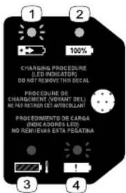
- Battery charge
status
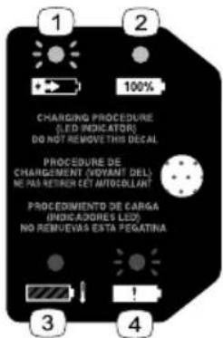
decal144-3094
144-3094
- The pack is charging.
battery3. The battery pack is or under appropriate temperature range.
- The pack charged.
battery4. Battery is fudhyarging fault

decal139-5210
139-5210
- W arning—read the Operator's Manual; stay away from moving parts; keep all guards in place; wear eye protection; do not conditions.
operate
in wet
WARNING To reduce risk of injury to persons, remove battery pack when not in use. See instruction manual for compatible TORO 60v devices and attachments.
AVERTISSEMENT Pour reduire les risques de blessures corporelles, retirez la batterie quand vous ne l'utilisez pas. Voir le manuel d'instructions pour les appareils et accessoires TORO 60v compatibles.
ADVERTENCIA Para reducir el riesgo de lesiones a personas, retire la batería cuando no esté en uso. Consulte el manual de instrucciones para ver los dispositivos y accesorios TORO 60v compatibles
WARNING: Cancer and Reproductive Harm - www.P65Warnings.ca.gov. For more information, please visit www.ttcoCAProp65.com
AVERTISSEMENT: Cancer et Troubles de l'appareil reproducteur - www.P65Warnings.ca.gov. Pour plus d'informations, veuillez visiter www.toro.com/CAProp65
ADVERTENCIA: Cáncer y Daño Reproductivo - www.P65Warnings.ca.gov. Para obtener más información, visite www.toro.com/CAProp65
139-5346
decal139-5346

Use the chart below to verify that all parts have been shipped.
| Procedure | Description | Qty . | Use |
| 1 | Allen wrench 1 | Unfold the handle. | |
| 2 | Auxiliary handle assembly Edger adjustment | Install handle. 1 the tool |
Important: The battery pack it. Before using the tool for Battery Pack (page 21).

Unfolding the Handle
Parts needed for this procedure:
1 Allen wrench
Procedure
- Unfold the handle (A of Fig
- Align the upper the locking shaft and button slide o the
Note: The locking button are secured (D of Figure 3
- Using the provided Allen connector until it is secure
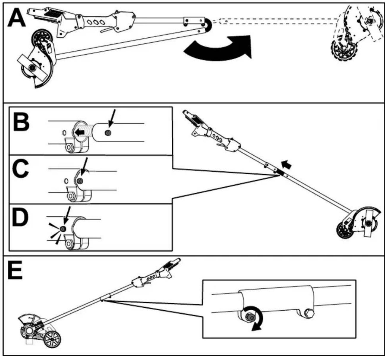
Figure 3
g537894
2
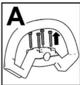
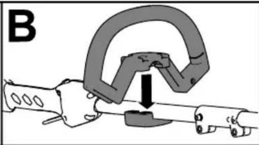
Installing the Auxiliary Handle
Parts needed for this procedure:
| 1 Auxiliary handle assembly |
| 1 Edger adjustment tool |
Procedure
- Separate 4 screws (A the auxiliary figure 4).
- Line handle up the auxiliary figure 4 handle
- Secure the auxiliary handle previously removed (C of
natural_image
Diagram of a mechanical clamp or clamp device with a downward arrow indicating force or movement (no text or symbols present)
natural_image
Mechanical assembly diagram showing a clamp or spring mechanism with pins and a downward arrow (no text or symbols)Figure
4
Product Overview
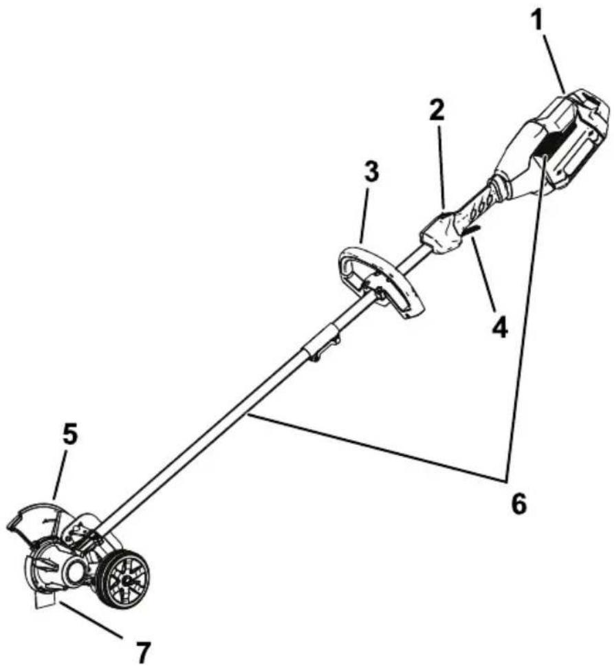
Figure 5
g429628
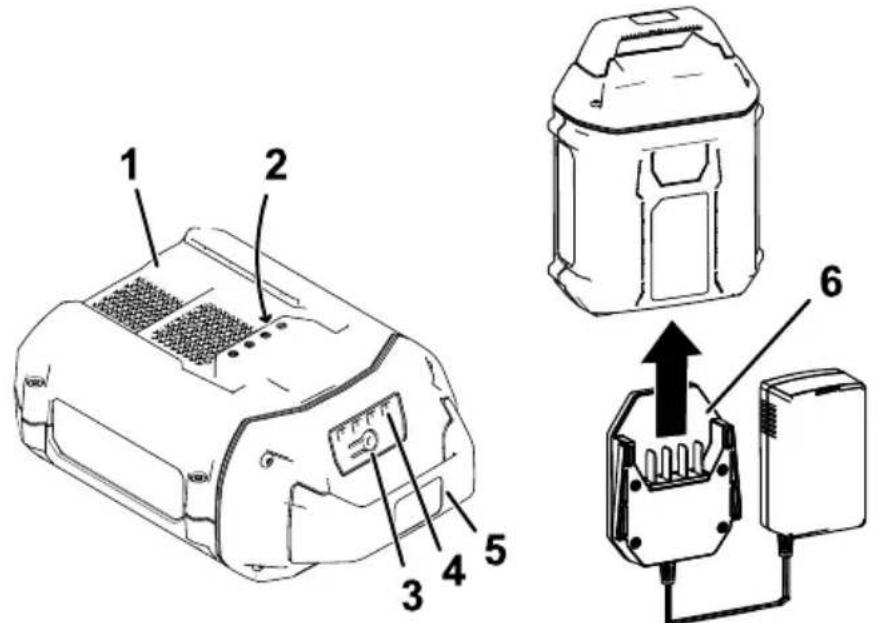
- Battery latch
- Guard
- Lockout button 6. Air venting areas
- Auxiliary handle 7. Blade
- Run trigger
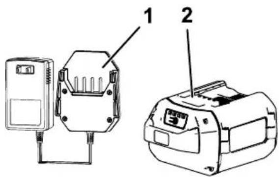
Figure 6
g330065
-
1A battery charger (included with Model 51833)
-
2.0 Ah battery pack (included with Model 51833)
Specifications
| Model 51833 | |
| Blade Length | 203 mm (8 inches) |
| Rated Voltage | 60V DC maximum, 54 VDC nominal usage |
| No-load Speed | 7000 rpm |
| W eight (without battery pack) | |
| Charger T ype | Flex-Force 60V lithi |
| Battery T ype | Flex-Force |
Appropriate
| Charge/store | the | battery | pack | at | ||
| Use the battery | pack | -30°C at | (-22°F) | to | ||
| Use the machine | 0°C a(32°F) to | 49°C (120°F)* | ||||
*Charging range.
time
will
increase
Store dry
the
tool,
battery
pack,
Attachments/Accessories
| A selection use with the machine | of T oro approved to enhance your Authorized Service for a list of all www .T oro.com |
T o ensure machine,
optimum
use
only
parts
performance
genuine
and
accessori
Replacement
be dangerous.
Operation
Starting the Edger
-
Align the cavity in the battery pack with the tongue on the handle housing ( Figure 7 ).
-
Push the battery pack into latch ( Figure 7 ).
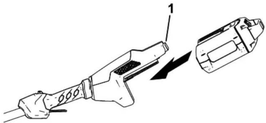
natural_image
Technical line drawing of a fuel injector with a component being inserted (no text or symbols)Figure 7
g333238
-
Battery latch
-
To start the edger, pull back the run trigger (Figure 8).
Note: Once the edger is ru

Figure 8
g333239
- Lockout button 2. Run
Shutting Off the Edger
T o shut of f the trimmer , release the trigger .
Whenever
you
are
not
using
from
the
work
area,
remove
Removing
the
Battery
Press
the
battery
latch
on
the
slide
the
battery
pack
out
of 1

natural_image
Technical line drawing of a fuel injector with a close-up view showing internal components (no text or symbols)Figure
9
g333240
1.
Battery
latch
Adjusting the Depth of Cut
-
Remove the battery from the edger.
-
Loosen track to the increase wing nut on the decrease
- Wing nut
- Adjust the depth so that th the machine is held in a norma
- T ighten the wing nut.
- Standing in a normal working and correct if necessary
Charging the Battery Pack
Important: The battery pack is not fully charged when you purchase it. Before using the tool for the charger and charge it u pack is fully charged. Read
Important: within the Charge appropriate the batte range;
Note: At any time, press the battery pack to display the cur
- Ensure charger that are the clear vents of any and dust
Figure
g536593
- Battery pack
-
Battery pack
4avity LED indicators
terminals -
Battery-charge-indicator
-
Charger
button
-
Line up the charger with ( Figure 1 1 ).
-
Slide the charger into the 1 1 ).
-
T o remove the charger, sl
-
Refer to the following table to interpret the LED indicator light on the battery charger.
| Indicator light | Indicates | |||
| Of f | No battery pack inserted | |||
| Green blinking | Battery | pack is | charging | |
| Green | Battery | pack is | charged | |
| Red | Battery temperature | pack | and/or range | battery |
| Red bl | Battery | pack | charging | fault* |
*Refer to T roubleshooting ( )
| Important: between | uses. | The | battery | can | ||
| If the from | battery the | charger; | will | not refer | be | used to |
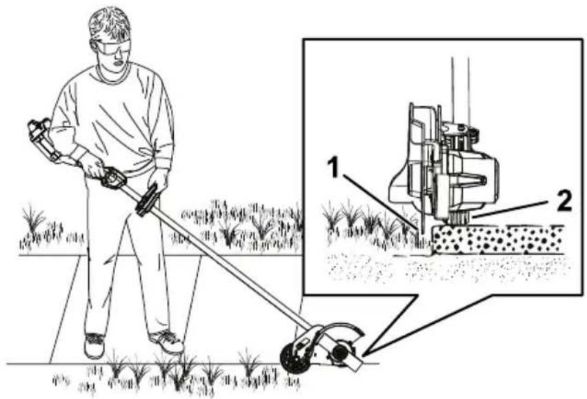
Operating T ips
- Hold the edger with your right hand on the rear handle and your le hand on the front handle.
- Keep a firm grip with both h
• The edger should be held at about hip height.
• The and edger similar will edges along areas.
- Cut at a steady pace. If the too fast; slow your pace. Do
• Light acceptable contact and of the will blade not a damage
• T o achieve wet soil or wet grass areas uneven edge. If the blade and remove the battery
Figure
12
g333294
-
Blade
-
Wheel
Maintenance
After each use of the edger , complete the following:
-
Remove the battery from the edger.
-
Wipe down the edger clean with or submerge it in water
-
Wipe or scrape clean the accumulation of debris.
-
Check and tighten all fastener or replace it.
-
Brush housing debris to prevent away from the motor
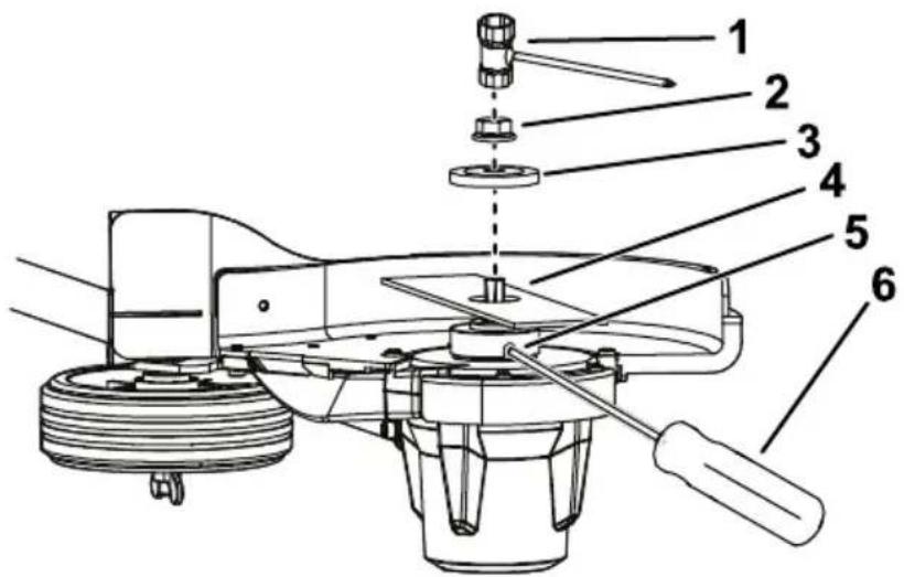
Replacing
If the blade Authorized
-
Ensure that the battery is
-
Secure included) the blade to the slot so in that the
Note: You may need to turn
- Remove adjustment the tool blade provided nut by
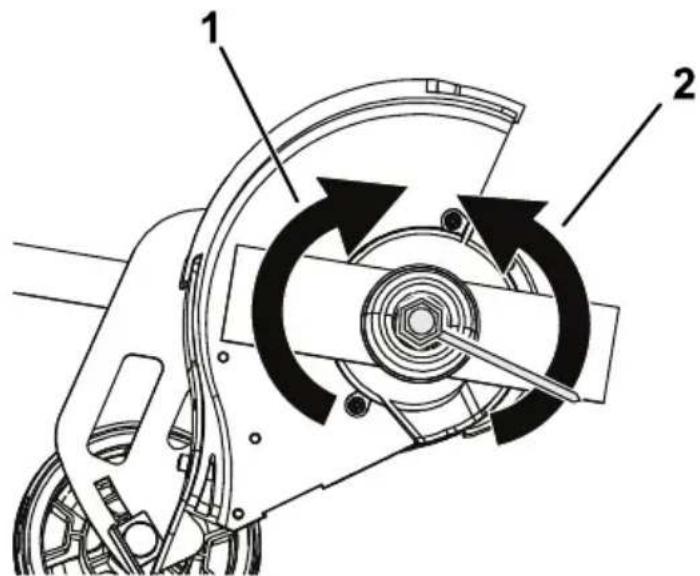
Figure 13
-
Rotate clockwise 2. Rotato blade loosen counterclockwise nut
-
Remove the blade washer and the old blade ( Figure 14 ).
Note: You may discard the old blade.
- Install washer
the and
new blade
blade nut.
Figure
14
g334037
- Edger
adjustment
tool
4.
- Blade
nut
-
Blade-secure
-
Blade
washer
6.
Screwdriver
(not
- T ighten provided
the ( Figure
blade
13 ).
nut
by
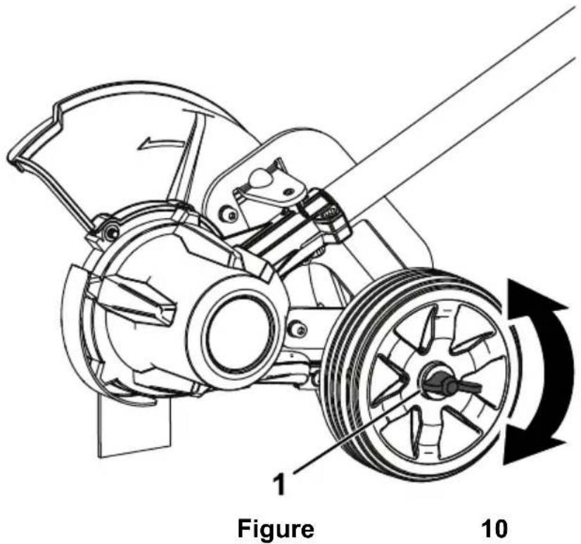
Replacing the Wheel
- Ensure that the battery is removed from the machine.
- Remove the wing nut, washer, bushings, wheel, rubber washer, wheel axle from the depth-of-cut
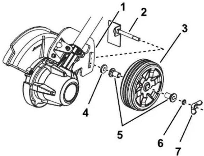
Figure
15
g334039
- Depth-of-cut
5rack Bushings
- Wheel
axle
- W
asher
-
Wheel
-
Wing
nut
- Rubber
washer
- Replace Service
Dealer
damaged
or
- Insert shown
the
wheel
axle
through
- Install nut
in
Figure
15
- T ighten
the
rubber
( Figure
washer
15 ).
the
wing
nut
to
seci
Replacing the Skid Plate
If the skid plate becomes worn or damaged, replace it; contact your Authorized Service Dealer .
- Ensure that the battery is
- Remove the 2 screws securir
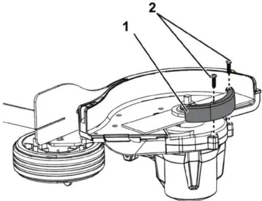
Figure 16
g344651
-
Skid plate
-
Screws
-
Replace previously
the skid
plate and
Storage
Important: Store the tool, battery pack, and charger only in temperatures that are within the appropriate range; refer to Specifications (page 17).
| Important: | |||||||
| remove | the | If battery | are | storing | |||
| pack | until | 1 | or | 2 | LED | pack indicators | |
| store | a | fully | charged | or fully | |||
| use | the | machine | again, | ||||
| light | turns | green | on | the charge | |||
| on | the battery | . | |||||
- Disconnect from the power the product supply or from the use.
- Do not store the tool with the
- Clean all foreign material fi
- When not in use, store the of the reach of children.
- Keep agents, the tool, battery as garden pack, chemic
• T o reduce the risk of serious pack outside or in vehicles. - Store the tool, battery pack, dry area.
Preparing the Battery Pack for Recycling
Important: Upon removal, cover the terminals of the battery pack with heavy-duty adhesive disassemble the battery pa
Contact Dealer the battery your local municipality or distributor for more .
 | Lithium-ion battery packscan be recycled at any particip facility in the Call2Recycle locate a participating retailer1-800-822-8837 or visit wv |
 | Lithium-ion battery packs (HEB) seal shown here, or greater , can be recycled in the Call2Recycle HEB dealer or retailer closest to |
If you cannot locate a participating questions about which recycling for , please visit the customer for your tool/equipment for m the battery pack. If you are located outside of Authorized Service Center (responsibly recycle the battery
T roubleshooting
Perform only the steps described in these instructions. All further inspection, maintenance, and repair work must be performed
authorized
service
center
or
solve
the problem
yourself.
Always
remove
the
battery
fr
maintaining,
or
cleaning
the
| Problem | Possible | Cause |
| The tool does | 1. That stattery installed2. The battery charged.3. The battery damaged.4. There is another electrical the tool. | 1. Removes not full replace tool. the to be that it is fully and latched.2. Remove pack is pack from charge it. 3. Replace is pack.4. Contact a service with |
| The tool does power . | 1. The not batterych capacity2. The air vents blocked. | 1. Reflete charge is pack low from . fully charge the pack.2. Clean face air |
| The tool is producing excessive noise. | There is debris vibration head of edger.2. The blade properly | 1. orClean the any from the cutting area.2. Is lighten then tightened. |
| The edger use. | stops The duration2. W alking or cutting fast. | 1. iRaiset too the g2. Slow too your the machine ef fectively |
| The battery charge quickly | 1. Pack battlespack or under temperature | 1. Moveis over the to appropriate dry ranged the is between and 40°C |
| Problem | Possible Cause Corrective Action | |
| The battery working. | 1. Therg battery charger is over or under the appropriate temperature range.2. The outlet that 2. Conthe your battery charger electrician is plugged into outlet does not have power | 1. Unplug the battery charger and move it to a place where and the temperature is between 40^ ( 104^ ). |
| The LED indicator the battery | IndicatoThe battery charging chargeor battery is over or under the appropriate temperature range. | 1. Unplug the battery charger and move battery charger battery pack where it is d temperature is between 5^ ( 41^ ) ( 104^ ). |
| The LED indicator on the battery blinking red. | 1. There light is the charging station between pack and2. The battery pack weak. | 1anRemover in the pack from the the charged battery plug the battery charger.the outlet, 10 seconds.battery charger outlet again and the battery battery charger LED indicator the battery still blinking red, this procedure If the LED light on the batter charger is still blinking red after 2 attempts, properly battery pack recycling2.isProperly battery pack recycling |
| Problem | Possible Cause Corrective Action |
| The tool does run continuously | 1. Therenist moisture on the leads of the battery pack.2. The battery is installed |
Notes:
Notes:
California Proposition 65 W arning Information
What is this warning?
Y ou may see a product for sale that has a warning

W ARNING:
Harm—www
Cancer
.p65W
What is Prop 65?
| Prop that list annually public | 65 may of chemicals, about | applies be chemicals, includes exposure | to in known hundreds to these | any or to cause | company brought to cause of chemicals. | operating into cancer of chemicals. | in California, birth fou |
| Prop product violation a chemicals to https://oag.ca.gov/prop65/faqs-view-all | |||||||
| A the of A | Prop “no a listed | 65 warning significant chemical | means risk without | that level”; | a company (2) attempting | has chosen to evaluate | |
Does this law apply
everywhere?
| Prop range wide websites | 65 of variety | warnings settings, or in | are including products. | required | but Additionally | under not | California limited, some to |
How
| Prop that standard | 65 require | standards | are 65 | often warning for | lead | more at is | stringent levels 0.5 | μg/day | that | |
| for | a Prop warnings | |||||||||
Why
| Products | sold | in | California | require | Prop | 65 |
| A company products, | but | involved other | in a companies | Prop making | 65 lawsuit | n similar |
| The enforcement | of Prop | 65 is inconsistent. | ||||
| Companies under at similar | Prop levels. | may 65; a | elect lack of | not to warnings | provide for | warnings a product |
Why
| T oro has decisions the presence provide significant T oro does enforce | has chosen about exposure risk" not Prop | to the of one limit range, provide 65 and subject | provide products or more requirements. out of these of an abundance warnings, to substantial | consumers they buy chemicals While it could Rev pe |

Count on it.
Manual del operador
Cortabordes Flex - Force Power System™ 60 V
natural_image
Line drawing of a mechanical tool with a long rod and flanged handle (no text or symbols)
Para obtener ayuda,
www .T oro.com/support
Figura 1
g428616
- Ubicación
de los números
de mo
N° de modelo
N° de serie
natural_image
Pure electrical circuit lines without any symbolsdecal161 - 3764
161 - 3764
- Estado
de carga

decal144 - 3094
144 - 3094
To reduce risk of injury to persons, remove battery pack when not in use.
See instruction manual for compatible TORO 60v devices and attachments.

AVERTISSEMENT
WARNING: Cancer and Reproductive Harm - www.P65Warnings.ca.gov. For more information, please visit www.ttcoCAProp65.com

over 40% of business may cause personal theft and damage, due to: lack of acute shock. Do not escape to suicide, Upper, or Refi. Do not interrupt outpail terminal. For doctor use only.
A CQUIN TO REVOKE THE RISK OF INJURY, USER MUST READ AND UNDERSTAND INSTRUCTION MANUAL. Change any Flex-Face set. Let us Technologies Banky. NOVATION

TO REDUCE THE RISK OF INJURY, USER MUST READ AND UNDERSTAND
INSTRUCTION MANUAL. Charge only Flex-Forte 50v Li-ion rechargeable battery may burst causing personal injury and damage. DANGER: risk of electric shock, vapor, or rain. Do not interconnect output terminal. For indoor use only.

The following table is in English.
CSA STD-E122 IN4 107.3


Other than Class 2 Battery Charger
Figura 5
g429628
Figura 6
g330065
natural_image
Technical line drawing of a fuel injector with a component being inserted (no text or symbols)Figura 7
g333238
- Cierre
de la batería
- Para apriete
arrancar el gatillo
Figura 8
g333239
- Botón
natural_image
Technical line drawing of a fuel injector with a separate component, showing internal components and motion direction (no text or symbols)Figura
9
g333240
1.
Cierre
de
la
batería
Figura 1 1
Figura
12
g333294
-
Cuchilla
-
Rueda
Mantenimiento
Figura 13
g334038
Figura 14
g334037
- Herramienta
4deCuchilajuste
del
cortaborde:
- T uerca
de la cuchilla
5.
- Arandela
Figura 15
g334039
Figura
16
g344651
-
Patín
-
T ornillos
-
Cambie
el patín
y sujételo
Almacenamiento
natural_image
Line drawing of a manual power tool with a lever and handle (no text or symbols)
Figure 1
g428616
- Emplacement
des numéros
de
N° de modèle
N° de série
Symbole de sécurité
natural_image
Pure electrical circuit lines without any symbolsdecal161 - 3764
161 - 3764
- État
de charge
de la ba
decal144 - 3094
144 - 3094
This image contains no text. The horizontal line is a stylistic or background element and must be ignored according to the rules.
les
temps
en place;
yeux;
humide.

WARNING
To reduce risk of injury to persons, remove battery pack when not in use. See instruction manual for compatible TORO 60v devices and attachment:

AVERTISSEMENT
WARNING: Cancer and Reproductive Harm - www.P65Warnings.ca.gov. For more information, please visit www.ttcoCAProp65.com

Do not expede to liquid, vapor, or rain. Do not interact with pure spherical. For indoor use only.
Other things of batteries may bury causing personal failure and damage. DAMGER: Tik of electric schools.
YOU NOW
ORVISECART: ORV 06/18 15:49 IN CHAPAT 30 AND ARE THE DATE OF

TO REDUCE THE RISK OF INJURY, USER MUST READ AND UNDERSTAND
NSTRUCTION MANUAL. Charge only Flex-Force 52v LI-ion rechargeable battery.
Other types of batteries may burst causing personal injury and damage. DANGER: risk of electric
Do not expose to liquid, vapor, or rain. Do not link connect output terminals. For indoor use only.

OUR RÉDUIRE LES AISQUES DE BLESSURE, L'UTILISATEUR DOIT LIRE ET
/ Camchi is there / 10. 875-9612 Pulified by / Eclichi Unaudenents only
CS8. VTD-2021 No. 2022


Other than Class 2 Delivery Charger
Audis que Chargour de batteries Class 2 Commander de l'education districts et de Class 3

800797


decal161 - 3785
161 - 3785
Mise en service
Pièces détachées
natural_image
Diagram of a clamp or measuring tool with a downward arrow indicating force or movement (no text or symbols present)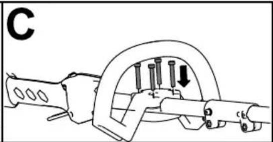
natural_image
Mechanical assembly diagram showing a clamp or spring mechanism with pins and a downward arrow (no text or symbols)Figure
4
g537897
Figure 5
g429628
Figure 6
g330065
natural_image
Technical line drawing of a fuel injector with a component being inserted (no text or symbols)Figure
7
g333238
- V errou
de
batterie
- Pour verrouillage
mettre
en
le coupe
arrière,
- bordur puis
Remarque:
pouvez
relâcher
Lorsque
le
bouton
le c
Figure
8
g333239
- Bouton
de
verrouillage
Gâchette
de
mar
natural_image
Technical line drawing of a fuel injector with a close-up view showing internal components (no text or symbols)Figure
9
g333240
1.
V
errou
de
batterie
g333293
Figure
12
g333294
-
Lame
-
Roue
Entretien
g334038
Figure 13
g334037
Figure 14
- Outil
de
réglage
- Lame du
coupe
- bordures
- Écrou de
lame
- Fente
de
blocage
- Rondelle
de lame
- Tournevis
(non
incl
- Serrez avec
l'écrou
de
la
lame
la clé
fournie
( Figure
Figure 15
g334039
Figure
16
g344651
- Patin
de
protection
2.
V
- Remplacez
retirées
précédemment.
le patin
de
prote