
51998 - Grass trimmer TORO - Free user manual and instructions
Find the device manual for free 51998 TORO in PDF.


| Product Type | Gasoline Grass Trimmer (Edger) |
| Brand | Toro |
| Model | 51998 (fits models 51954 and 51974) |
| Engine | 25.4 cc, 2-stroke, complete crankshaft |
| Cutting Width | Model 51954: 43.2 cm (17 in); Model 51974: 45.7 cm (18 in) |
| Line Diameter | 2.4 mm (0.095 in) |
| Weight | Model 51954: 5.3 kg; Model 51974: 5.6 kg |
| Fuel | Unleaded 87 octane gasoline and 2-stroke oil mix (50:1) |
| Fuel Tank Capacity | Approximately 0.4 L (estimated) |
| Starting System | Manual recoil start, primer bulb, choke (FULL/HALF/RUN) |
| Cutting Head | Reel Easy, bump or manual line advance |
| Line Type | 2.4 mm nylon monofilament |
| Front Handle | Yes, adjustable |
| Grass Deflector | Yes, with line cutter |
| Spark Arrestor | Yes, replaceable (part no. 000998216) |
| Spark Plug | Champion RCJ4 |
| Air Filter | Cleanable with soapy water, lubricatable |
| Routine Maintenance | Clean air filter every 5 hours, replace spark plug annually |
| Recommended Use | Trimming grass, weeds, sidewalks and driveway edges |
| Safety | Wear safety glasses and hearing protection, keep 15 m away from people |
| Warranty | 2 years for residential use, 90 days for commercial use |
| Customer Service | 1-866-574-9242 (USA) or 1-866-574-9243 (Canada) |
Frequently Asked Questions - 51998 TORO
User questions about 51998 TORO
0 question about this device. Answer the ones you know or ask your own.
Ask a new question about this device
Download the instructions for your Grass trimmer in PDF format for free! Find your manual 51998 - TORO and take your electronic device back in hand. On this page are published all the documents necessary for the use of your device. 51998 by TORO.
USER MANUAL 51998 TORO
17 in. String Trimmer - Curved Shaft Model No. 51954-310000001 & Up 18 in. String Trimmer - Straight Shaft Model No. 51974-310000001 & Up
STOP
If you have questions concerning your trimmer, please call us at 1-866-574-9242 (US) or 1-866-574-9243 (Canada).

text_image
STOPREAD THIS INFORMATION
Before you use your new trimmer, read the following helpful hints to get you started.
Fueling

WARNING:
Gasoline and its vapors are highly flammable and explosive. To prevent serious personal injury and property damage, handle it with care. Keep away from ignition sources and open flames, handle outdoors only, do not smoke and wipe up spills immediately.
- Obtain a clean container that is approved for use with gasoline.
- Mix all of the 2-cycle oil provided with 1 US gallon of 87-octane, unleaded gasoline (50:1).
- Fill the trimmer's gas tank carefully.
Cold Starting vs. Warm Starting
When you restart the trimmer and you are not sure whether the engine is still warm, set the choke lever to RUN and pull the starter cord. If the engine does not start within 5 pulls, refer to “To Start a Cold Engine” later in this manual.
Flooded Engine
Will the engine start? If not, it may be flooded. Relax, this is easy to correct. Set the choke lever to RUN. Squeeze the trigger and pull the starter cord quickly for 10 to 12 pulls.
If the engine does not start, refer to "Troubleshooting" later in this manual or call toll-free at

text_image
NEED HELP ? SAIN! 1-866-574-9242 (US) or 1-866-574-9243 (Canada)For questions concerning your trimmers, call us toll free at 1-866-574-9242 (US) or 1-866-574-9243 (Canada).
⚠ WARNING: The engine exhaust from this product contains chemicals known to the State of California to cause cancer, birth defects or other reproductive harm.
CALIFORNIA PROPOSITION 65
Table of Contents
Introduction......4
General Safety Rules....5
Specific Safety Rules 6
Symbols....7
Product Labels 8
Features 9-10
Product Specifications 9
Assembly....11-13
Unpacking....11
Connecting the Attachment to the Upper Shaft....12
Removing the Attachment from the Upper Shaft 12
Attaching the Front Handle ....12
Attaching the Grass Deflector....13
Operation....14
Applications....14
Fueling and Refueling the Trimmer....14
Starting the Product 15
Stopping the Product....15
Operating the Trimmer 16
To Advance the Cutting Line....17
Cutting Tips ....17
Installing Line in Reel Easy String Head ....19
Maintenance....19
Cleaning the Product....19
Servicing the Product....19
Checking the Fuel Cap....19
Cleaning the Air Filter 19
Replacing the Spark Arrestor....20
Replacing the Spark Plug....20
Idle Speed Adjustment....21
Storing the Product 21
Transporting the Product 21
Installing Reel Easy String Head....21
Emissions Maintenance Schedule....22
High Altitude Engine Operation 22
Troubleshooting 23
Warranty 24-26
Thank you for purchasing a Toro product.
We would like for you to be completely satisfied with your new product, so feel free to contact an authorized service dealer for help with service, genuine Toro parts, or other information you may require.
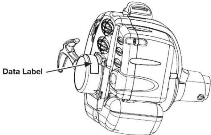
Whenever you contact an authorized service dealer, always know the model and serial numbers of the product. These numbers will help the service representative provide exact information about your specific product. You will find the model and serial number decal located on the motor housing.
For your convenience, write the product model and serial numbers in the space below.
| Model No. | |
| Serial No. |
text_image
Data LabelRead this manual carefully to learn how to operate and maintain your product correctly. Reading this manual will help you and others avoid personal injury and damage to the product. Although Toro designs, produces, and markets safe, state-of-the-art products, you are responsible for using the product properly and safely. You are also responsible for training persons you allow to use the product about safe operation.
The Toro warning system in this manual identifies potential hazards and has special safety messages that help you and others avoid personal injury, even death. DANGER, WARNING, and CAUTION are signal words that identify the level of hazard. However, regardless of the hazard, be extremely careful. Two other words, “Important” and “Note,” highlight information.

WARNING:
Read and understand all instructions. Failure to follow all instructions may result in electric shock, fire and/or serious personal injury.
Read All Instructions
For safe operation, read and understand all instructions before using this product. Follow all safety instructions. Failure to follow all safety instructions listed below, can result in serious personal injury.
■ Do not allow children or untrained individuals to use this unit.
■ Never start or run the engine in a closed or poorly ventilated area; breathing exhaust fumes can kill.
- Clear the work area before each use. Remove all objects such as rocks, broken glass, nails, wire, or loose string which can be thrown or become entangled in the cutting line or blade.
■ Always wear eye protection with side shields marked to comply with ANSI Z87.1 along with hearing protection when operating this equipment.
■ Wear heavy, long pants, long sleeves, boots, and gloves. Do not wear loose fitting clothing, short pants, sandals, or go barefoot. Do not wear jewelry of any kind.
■ Heavy protective clothing may increase operator fatigue, which could lead to heat stroke. During weather that is hot and humid, heavy work should be scheduled for early morning or late afternoon hours when temperatures are cooler.
■ Product users on United States Forest Service land, and in some states, must comply with fire prevention regulations. This product is equipped with a spark arrestor; however, other user requirements may apply. Check with your federal, state, or local authorities.
- Never operate this unit on the operator's left side.
- Secure long hair above shoulder level to prevent entanglement in moving parts.
- Keep all bystanders, children, and pets at least 50 ft. away. Bystanders should be encouraged to wear eye protection. If you are approached, stop the engine and cutting attachment. In the case of bladed units, there is the added risk of injury to bystanders from being struck with the moving blade in the event of a blade thrust or other unexpected reaction of the saw.
■ Do not operate this unit when you are tired, ill, or under the influence of alcohol, drugs, or medication.
■ Do not operate in poor lighting.
- Keep firm footing and balance. Do not overreach. Overreaching can result in loss of balance or exposure to hot surfaces.
- Keep all parts of your body away from any moving part.
■ To avoid hot surfaces, never operate the unit with the bottom of the engine above waist level.
■ Do not touch area around the muffler or cylinder of the unit, these parts get hot from operation. Contact with
hot surfaces could result in possible serious personal injury.
■ Always stop the engine and remove the spark plug wire before making any adjustments or repairs except for carburetor adjustments.
■ Inspect the unit before each use for loose fasteners, fuel leaks, etc. Replace any damaged parts before use.
■ The cutting attachment should never rotate at idle during normal use. The cutting attachment may rotate at idle during carburetor adjustments.
It has been reported that vibrations from hand-held tools may contribute to a condition called Raynaud's Syndrome in certain individuals. Symptoms may include tingling, numbness, and blanching of the fingers, usually apparent upon exposure to cold. Hereditary factors, exposure to cold and dampness, diet, smoking, and work practices are all thought to contribute to the development of these symptoms. It is presently unknown what, if any, vibrations or extent of exposure may contribute to the condition. There are measures that can be taken by the operator to possibly reduce the effects of vibration:
a) Keep your body warm in cold weather. When operating the unit wear gloves to keep hands and wrists warm. It is reported that cold weather is a major factor contributing to Raynaud's Syndrome.
b) After each period of operation, exercise to increase blood circulation.
c) Take frequent work breaks. Limit the amount of exposure per day.
d) Keep the tool well maintained, fasteners tightened, and worn parts replaced.
If you experience any of the symptoms of this condition, immediately discontinue use and see your physician about these symptoms.
■ Mix and store fuel in a container approved for gasoline.
■ Mix fuel outdoors where there are no sparks or flames. Wipe up any fuel spillage. Move 30 ft. away from refueling site before starting engine. Slowly remove the fuel cap after stopping engine. Do not smoke when refueling.
■ Stop the engine and allow to cool before refueling or storing the unit.
- Allow the engine to cool; empty the fuel tank into a container approved for fuel and secure the unit from moving before transporting in a vehicle.
■ Wear your protective equipment and observe all safety instructions. For units equipped with a clutch, be sure the cutting attachment stops turning when the engine idles. When the unit is turned off make sure the cutting attachment has stopped before the unit is set down.
Specific Safety Rules For Trimmer Use
■ Inspect before use. Replace damaged parts. Make sure fasteners are in place and secure. Check for fuel leaks.
■ Replace string head if cracked, chipped, or damaged in any way. Be sure the string head or blade is properly installed and securely fastened. Failure to do so can cause serious injury.
■ Make sure all guards, straps, deflectors, and handles are properly and securely attached.
- Never use blades, flailing devices, wire, or rope. Use only the manufacturer's replacement line in the cutting head. Do not use any other cutting attachment. To install any other brand of cutting head to this string trimmer can result in serious personal injury.
■ Never operate unit without the grass deflector in place and in good condition.
- Maintain a firm grip on both handles while trimming. Keep string head below waist level. Never cut with the string head located over 30 in. or more above the ground.
Symbols
| The following signal words and meanings are intended to explain the levels of risk associated with this product. SYMBOL SIGNAL MEANING | ||
 | DANGER: | Indicates an imminently hazardous situation, which, if not avoided, will result in death or serious injury. |
 | WARNING: | Indicates a potentially hazardous situation, which, if not avoided, could result in death or serious injury. |
 | CAUTION: | Indicates a potentially hazardous situation, which, if not avoided, may result in minor or moderate injury. |
| CAUTION: | (Without Safety Alert Symbol) Indicates a situation that may result in property damage. | |
Some of the following symbols may be used on this product. Please study them and learn their meaning for safe operation of this product.
SYMBOL NAME EXPLANATION
 | Safety Alert Indicates a potential personal injury hazard. | |
 | Read Operator's Manual | To reduce the risk of injury, user must read and understand operator's manual before using this product. |
 | Eye and Hearing Protection | Always wear eye protection with side shields marked to comply with ANSI Z87.1 along with hearing protection when operating this equipment. |
 | Keep Bystanders Away | Keep all bystanders at least 50 ft. away. |
 | Ricochet | Thrown objects can ricochet and result in personal injury or property damage. |
 | No Blade | Do not install or use any type of blade on a product displaying this symbol. |
 | Gasoline and Oil | Use unleaded gasoline intended for motor vehicle use with an octancee rating of 87 [(R + M)/2] or higher. This product is powered by a 2-cycle engine and requires pre-miseing gasoline and 2-cycle oil. |
Product labels and instructions are easily visible to the operator and are located near any area of potential danger. Replace damaged or lost labels.
Part No. 940686064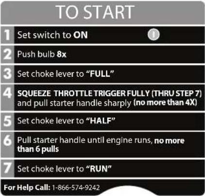 | Part No. 940864001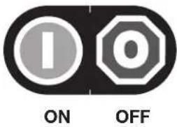 |
Part No. 940657034 | Part No. 940230132 |
Part No. 940865001 | Part No. 940627020 |
Features
Product Specifications
Name Specification
Engine 25.4 cc Full Crank
Cutting Width
Model No. 51954 17 in.
Model No. 51974 18 in.
Line Size .095 in.
Weight
Model No. 51954 11.6 lbs.
Model No. 51974 12.5 lbs.
Know Your Trimmer
See Figure 1.
Before attempting to use this product, familiarize yourself with all operating features and safety rules.
Engine
The engine is powerful and easy to start. It is effectively counterbalanced, which allows for less vibration and more durability.
Dual Line
The dual line permits more efficient cutting than a single line.
Grass Deflector
The grass deflector helps protect you from flying debris.
Ergonomic Design
The design of the product provides for easy handling. It is designed for comfort and ease of grasp when operating in different positions and at different angles.

text_image
Dual Line The dual line permits more efficient cutting than a single line. Curved Shaft Trimmer (Model No. 51954) Front Handle On/Stop Switch Throttle Trigger Fuel Cap Choke Lever Starter Grip and Rope On/Stop Switch Choke Lever Starter Grip and Rope Fuel Cap Dual Line Curved Shaft Grass Deflector Knob Knob Throttle Trigger Front Handle Knob Straight Shaft Trimmer (Model No. 51974) Dual Line Straight Shaft Grass Deflector Figure 1Figure 1
Unpacking
This product requires assembly.
■ Carefully remove the product and any accessories from the box. Make sure that all items listed in the packing list are included.

WARNING:
Do not use this product if any parts on the packing list are already assembled to your product when you unpack it. Parts on this list are not assembled to the product by the manufacturer and require customer installation. Use of a product that may have been improperly assembled could result in serious personal injury.
■ Inspect the product carefully to make sure no breakage or damage occurred during shipping.
■ Do not discard the packing material until you have carefully inspected and satisfactorily operated the product.
If any parts are damaged or missing, please call 1-866-574-9242 (US) or 1-866-574-9243 (Canada) for assistance.
Packing List
51954 Curved Shaft Trimmer
Upper shaft (Power head)
Curved Shaft Attachment
Front Handle
Curved shaft grass deflector
Lubricant
Hanger cap
Operator's Manual
51974 Straight Shaft Trimmer
Upper shaft (Power head)
Straight Shaft Attachment
Front Handle
Straight shaft grass deflector
Lubricant
Hanger cap
Operator's Manual

WARNING:
If any parts are damaged or missing do not operate this product until the parts are replaced. Use of this product with damaged or missing parts could result in serious personal injury.

WARNING:
Do not attempt to modify this product or create accessories not recommended for use with this product. Any such alteration or modification is misuse and could result in a hazardous condition leading to possible serious personal injury.

WARNING:
To prevent accidental starting that could cause serious personal injury, always disconnect the engine spark plug wire from the spark plug when assembling parts.
Connecting the Attachment to the Upper Shaft
See Figure 2.

WARNING:
Be certain the knob is fully tightened before operating equipment; check it periodically for tightness during use to avoid serious personal injury.
Follow these steps to connect the attachment to the upper shaft.
- Loosen the knob by turning it counterclockwise.
- Remove the end cap from the attachment shaft.
- Align the button on the attachment shaft with the guide recess on the upper shaft.
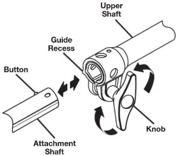
text_image
Button Attachment Shaft Guide Recess Upper Shaft KnobFigure 2
- Slide the attachment shaft into the upper shaft until the attachment shaft clicks into place.
Note: You may need to turn the attachment shaft to properly align the two shafts.
- Tighten the knob securely by turning it clockwise.
Removing the Attachment from the Upper Shaft
See Figure 2.
Follow these steps to remove the attachment from the upper shaft.
- Loosen the knob by turning it counterclockwise.
- Push the button while pulling out the attachment.
Attaching the Front Handle
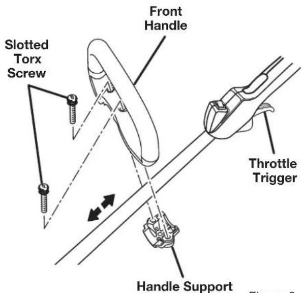
See Figure 3.
Follow these steps to attach the front handle.
- Remove the slotted Torx ^TM screws to separate the handle from the handle support.
text_image
Slotted Torx Screw Front Handle Throttle Trigger Handle Support Figure 9Figure 3
- Press the front handle onto the top of the upper shaft, in the position indicated by the arrow on the shaft, angling the handle toward the throttle trigger.
- Place the front handle along the upper shaft to a position that allows for comfortable operation.
- Place the handle support on the bottom of the shaft on the opposite side of the front handle.
- Secure the handle with the slotted Torx ^TM screws.
Note: Do not cover any portion of the warning label with the front handle.
Attaching the Grass Deflector
Attaching the grass deflector differs depending on the type of trimmer: curved shaft or straight shaft.

WARNING:
The line cut-off blade on the grass deflector is sharp. Avoid contact with the blade. Failure to avoid contact can result in serious personal injury.

WARNING:
Always attach the grass deflector prior to operating trimmer. Failure to attach the grass deflector may result in debris being thrown at the operator and result in serious injury.
To Attach the Curved Shaft Grass Deflector Model No. 51954
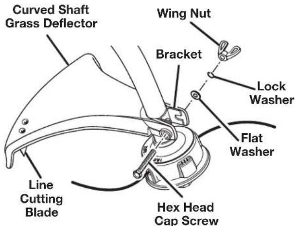
See Figure 4.
Follow these steps to attach the curved shaft grass deflector.
- Remove the hex head cap screw, flat washer, lock washer, and wing nut from the grass deflector.
- Press the grass deflector onto the bottom of the curved shaft as shown.
- Insert the hex head cap screw through the grass deflector bracket.
- Place the flat washer and lock washer on the hex head cap screw.
- Place the wing nut on the hex head cap screw and turn clockwise to secure.
text_image
Curved Shaft Grass Deflector Wing Nut Bracket Lock Washer Flat Washer Line Cutting Blade Hex Head Cap ScrewFigure 4
To Attach the Straight Shaft Grass Deflector Model No. 51974
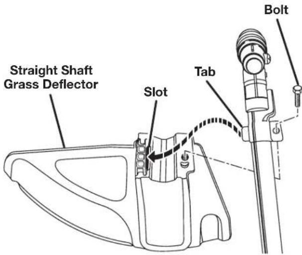
See Figure 5.
Follow these steps to attach the straight shaft grass deflector.
- Remove the bolt from the grass deflector.
- Insert the tab on the mounting bracket in the slot on the grass deflector.
- Align the screw hole in the mounting bracket with the screw hole in the grass deflector.
- Insert the bolt through the mounting bracket and into the grass deflector.
- Tighten the bolt securely.
text_image
Straight Shaft Grass Deflector Slot Tab BoltFigure 5

WARNING:
Do not allow familiarity with this product to make you careless. Remember that a careless fraction of a second is sufficient to inflict serious injury.

WARNING:
Always wear eye protection with side shields marked to comply with ANSI Z87.1, along with hearing protection. Failure to do so could result in objects being thrown into your eyes and other possible serious injuries.

WARNING:
Do not use any attachments or accessories not recommended by the manufacturer of this tool. The use of attachments or accessories not recommended can result in serious personal injury.
Applications
Use this product for the following applications:
■ Cutting grass, weeds, and light undergrowth
■ Edging along sidewalks and driveways
Fueling and Refueling the Trimmer

WARNING:
Gasoline and its vapors are highly flammable and explosive. To prevent serious personal injury and property damage, handle it with care.
Keep away from ignition sources and open flames, handle outdoors only, do not smoke and wipe up spills immediately.
Fuel Mixture
This product is powered by a 2-cycle engine and requires pre-mixing gasoline and 2-cycle lubricant. Pre-mix unleaded gasoline and 2-cycle engine lubricant in a clean 1 gallon container approved for gasoline.
Recommended fuel: This engine is certified to operate on unleaded gasoline intended for automotive use.
Mix a high quality 2-cycle engine lubricant at 2.6 oz. per gallon (US).
Do not use automotive lubricant or 2-cycle outboard lubricant.
DO NOT mix quantities larger than usable in a 30 day period.
HIGH QUALITY 2-CYCLE ENGINE LUBRICANT
GASOLINE LUBRICANT
1 gallon (US) 2.6 oz.
1 1 tcr 20 cc (20 ml)
Filling Tank
■ Clean surface around fuel cap to prevent contamination.
■ Loosen fuel cap slowly by turning counterclockwise. Rest the cap on a clean surface.
■ Carefully pour fuel into the tank. Avoid spillage.
■ Prior to replacing the fuel cap, clean and inspect the gasket.
■ Immediately replace fuel cap and hand tighten by turning clockwise. Wipe up any fuel spillage.
■ Move at least 30 ft. away from refueling area before starting the product.
NOTE: It is normal for smoke to be emitted from a new engine after first use.

WARNING:
Always shut off engine before fueling. Never add fuel to a machine with a running or hot engine. Move at least 30 ft. from refueling site before starting engine. Do not smoke and stay away from open flames and sparks. Failure to safely handle fuel could result in serious personal injury.
Oxygenated Fuels
Some conventional gasolines are blended with alcohol or an ether compound. These gasolines are collectively referred to as oxygenated fuels. To meet clean air standards, some areas of the United States and Canada use oxygenated fuels to help reduce emissions.
If using an oxygenated fuel, make sure it is unleaded and meets the minimum octane rating requirements. Before using an oxygenated fuel, try to confirm the fuel's contents. Some states/provinces require this information to be posted on the pump. The following are the EPA approved percentages of oxygenates:
Ethanol (ethyl or grain alcohol) 10% by volume. You may use gasoline containing up to 10% ethanol by volume. Gasoline containing ethanol may be marketed under the name “Gasohol.” Do not use E85 fuel.
MTBE (methyl tertiary butyl ether) 15% by volume. You may use gasoline containing up to 15% MTBE by volume.
Methanol (methyl or wood alcohol) 5% by volume. You may use gasoline containing up to 5% methanol by volume as long as it also contains cosolvents and corrosion inhibitors to protect the fuel system. Gasoline containing more than 5% methanol by volume may cause starting and/or
performance problems. It may also damage metal, rubber, and plastic parts of the product or your fuel system.
If you notice any undesirable operating symptoms, try another service station or switch to another brand of gasoline.
NOTE: Fuel system damage or performance problems resulting from the use of an oxygenated fuel containing more than the percentages of oxygenates stated previously are not covered under warranty.
Starting the Product
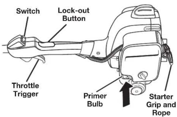
See Figures 6 - 8.
Starting the product differs depending on whether the engine is cold or warm. Refer to the label on the air filter cover.
To Start a Cold Engine:
Follow these steps to start a cold engine.
- Lay the product on a flat, bare surface.
- Toggle the switch to the I (ON) position.
- Push the primer bulb approximately eight times.
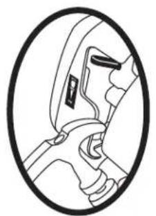
- Set the choke lever to FULL.
- Depress lock-out button and squeeze throttle trigger fully (thru step 7) and pull starter handle sharply until engine attempts to start (no more than 4x).
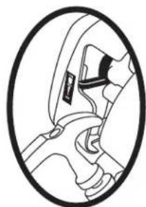
- Set the choke lever to HALF.
- Pull starter handle until engine runs, no more than 6 pulls.
- Set the choke lever to RUN.
NOTE: In cooler environments, additional pulls of the starter handle may be required with the choke lever in the FULL position.
text_image
Switch Lock-out Button Throttle Trigger Primer Bulb Starter Grip and RopeFigure 6
natural_image
Cross-sectional diagram of a vehicle head and neck (no text or labels)Set Choke to FULL
natural_image
Diagram of a car steering wheel and dashboard (no text or labels)Set Choke to RUN
Figure 7
To Start a Warm Engine:
Follow these steps to start a warm engine.
- Lay the product on a flat, bare surface.
- Toggle the switch to the I (ON) position.
- Push the primer bulb up to eight times.
- Set the choke lever to RUN.
- Depress lock-out button and squeeze throttle trigger fully, pull the starter cord.
Note: If the product does not start, repeat the previous steps.
Stopping the Product
See Figure 8.
Follow these steps to stop the product.
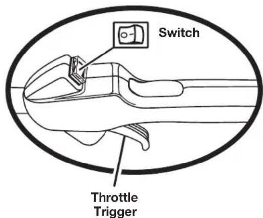
Release the trigger.
Toggle the switch to the O (OFF) position.
text_image
Switch Throttle TriggerFigure 8
Operating the Trimmer
Operating the trimmer differs, depending on whether you are using the curved shaft trimmer or the straight shaft trimmer.

WARNING:
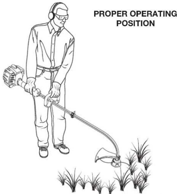
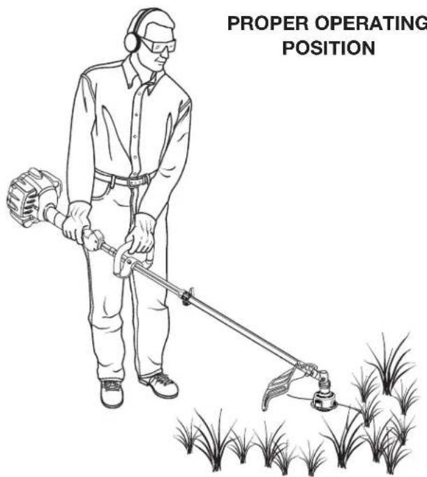
Engine housing may become hot during trimmer operation. Do not rest or place your arm, hand, or any body part against the engine housing during trimmer operation. Only hold the trimmers as shown in Figure 9 and 10 with all body parts clear of engine housing. Extended contact with the engine housing may result in burns or other injuries.

WARNING:
Always position the unit on the operator's right side. The use of the unit on the operator's left side will expose the user to hot surfaces and can result in possible burn injury.

WARNING:
To avoid burns from hot surfaces, never operate unit with the bottom of the engine above waist level.
To Operate the Curved Shaft Trimmer (Model No. 51954)
See Figure 9.
Follow these steps to operate the curved shaft trimmer.
- Start the trimmer.
- Hold the trimmer at waist level with your right hand on the throttle trigger and your left hand on the front handle.
- Place the product on the right side of your body with the engine behind and away from your body.
- Trim grass and weeds in a right-to-left motion with the line parallel to the ground.
text_image
PROPER OPERATING POSITIONFigure 9
To Operate the Straight Shaft Trimmer (Model No. 51974)
See Figure 10.
Follow these steps to operate the straight shaft trimmer.
- Start the trimmer.
- Hold the trimmer at waist level with your right hand on the throttle trigger and your left hand on the front handle.
- Place the product on the right side of your body with the engine behind and away from your body.
- Trim grass and weeds in a left-to-right motion with the line parallel to the ground.
text_image
PROPER OPERATING POSITIONFigure 10
To Advance the Cutting Line
See Figure 11.
Line advance is controlled by tapping the string head on grass while running engine at full throttle.
■ Run engine at full throttle.
Tap the knob on ground to advance line. The line advances each time the knob is tapped. Do not hold the knob on the ground.
Note: The line trimming cut-off blade on the grass deflector will cut the line to the correct length.
Note: If the line is worn too short you may not be able to advance the line by tapping it on the ground. If so, stop the engine and manually advance the line.
To advance the cutting line manually:
■ Stop the engine and disconnect the spark plug wire.
■ Push the knob in while pulling on line(s) to manually advance the line.

text_image
Retaining Cap Figure 14Figure 11
Cutting Tips
See Figures 12 and 13.
- Avoid hot surfaces by always keeping the tool away from your body. (Proper operating position is shown in Figures 9 and 10.)
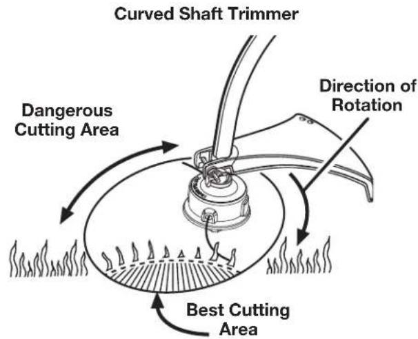
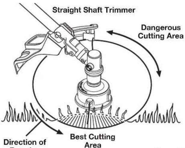
- Keep the trimmer tilted toward the area being cut; this is the best cutting area.
- The curved shaft trimmer cuts when passing the unit from right to left, the straight shaft trimmer cuts when passing the unit from left to right. This will avoid throwing debris at the operator. Avoid cutting in the dangerous area shown in figures 12 and 13.
- Use the tip of string to do the cutting; do not force string head into uncut grass.
- Wire and picket fences cause extra string wear, even breakage. Stone and brick walls, curbs and wood may wear string rapidly.
- Avoid trees and shrubs. Tree bark, wood moldings, siding and fence posts can easily be damaged by the string.
text_image
Curved Shaft Trimmer Direction of Rotation Dangerous Cutting Area Best Cutting AreaFigure 12
text_image
Straight Shaft Trimmer Dangerous Cutting Area Direction of Cutting Area Best Cutting AreaFigure 13
Installing Line in Reel Easy String Head
See Figures 14 - 15..
Use .095 in./2.4 mm diameter monofilament line.
■ Stop the engine and disconnect the spark plug wire.
■ Cut one piece of line approximately 25 ft. in length.
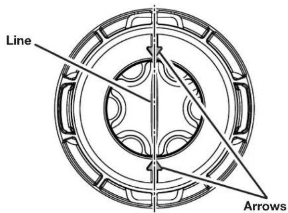
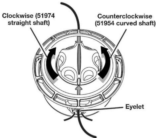
■ Rotate knob on string head until line on knob aligns with arrows on top of string head.
■ Insert one end of line into eyelet located on either side of the string head and push until line comes out through eyelet on the other side. Continue to push line through the string head until the middle section of the line is inside the string head and line outside the string head is evenly divided on each side.
■ While holding the string head in one hand with your other hand, rotate the knob on the string head to wind the line. If using the 51954 (curved shaft), knob should be rotated counterclockwise. If using the 51974 (straight shaft), knob should be rotated clockwise. Wind the line until approximately 8 in. remains protruding from the string head.
text_image
Line ArrowsFigure 14
text_image
Clockwise (51974 straight shaft) Counterclockwise (51954 curved shaft) EyeletFigure 15

WARNING:
Use only Toro replacement parts when servicing this product. Use of any other parts may create a hazard or cause product damage.

WARNING:
Always wear eye protection with side shields marked to comply with ANSI Z87.1, along with hearing protection. Failure to do so could result in objects being thrown into your eyes and other possible serious injuries.

WARNING:
Before inspecting, cleaning, or servicing the machine, shut off engine, wait for all moving parts to stop, and disconnect spark plug wire and move it away from spark plug. Failure to follow these instructions can result in serious personal injury or property damage.
Cleaning the Product
■ Stop the product before cleaning.
■ Clean the exterior of the product with a damp cloth.
■ Avoid using solvents when cleaning plastic parts. Most plastics are susceptible to damage from various types of commercial solvents and may be damaged by their use.
■ Wipe or scrape the trimmer head and spool area when they accumulate dirt or clippings.
■ Scrape debris away from air intake vents on both sides of the motor housing.
CAUTION:
Keeping air intake vents free of grass and debris prevents motor overheating and possible failure.
Servicing the Product
- Check and tighten all fasteners. If any part is damaged or lost, repair it or replace it.
Checking the Fuel Cap

WARNING:
Check for fuel leaks. A leaking fuel cap is a fire hazard and must be replaced immediately. If you find any leaks, correct the problem before using the product. Failure to do so could result in a fire that could cause serious personal injury.
The fuel cap contains a non-serviceable filter and check valve. A clogged fuel filter causes poor engine performance. If performance improves when the fuel cap is loosened, the check valve may be faulty or the filter may be clogged. Replace the fuel cap if necessary.
Cleaning the Air Filter
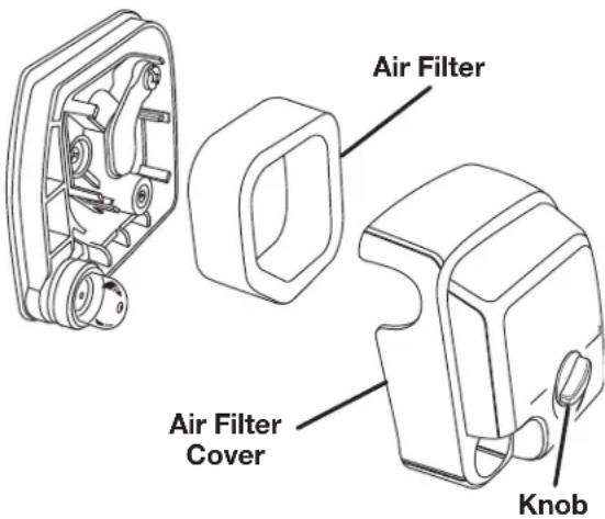
See Figure 16 and Figure 18.
Clean the air filter as indicated by the maintenance schedule. Follow these steps to clean the air filter.
- Stop the trimmer.
- Remove the spark plug boot.
- Loosen the air filter cover by turning the knob counterclockwise.
- Remove the air filter cover.
- Remove the air filter.
- Clean the air filter with warm soapy water.
- Rinse the air filter and let it dry completely.
- Work two drops of oil into the air filter.
- Replace the air filter (fits only one way).
-
Replace the air filter cover.
-
Tighten the air filter cover by turning the knob clockwise.
-
Replace the spark plug boot.
Note: Replace the air filter as indicated by the maintenance schedule.
text_image
Air Filter Air Filter Cover KnobFigure 16
Replacing the Spark Arrestor
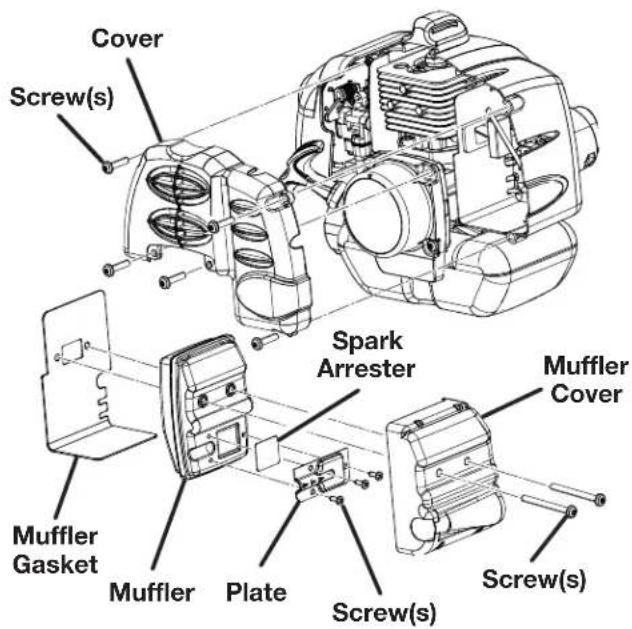
See Figure 17.
Note: Depending on the type of fuel used, the type and amount of oil used, and/or your operating conditions, the exhaust port and muffler may become blocked with carbon deposits. If you notice a power loss with your gas powered tool, you may need to remove these deposits to restore performance. We highly recommended that only qualified service technicians perform this service.
The spark arrester may need to be replaced after repeated use. If replacement is necessary, use Toro part number 000998216.
To replace the spark arrester:
- Remove the five screws that hold the cover.
Note: Removing these screws requires the use of a T20 and T25 torx screwdriver. - Remove the cover.
- Remove the two screws holding the muffler assembly in place.
- Remove the muffler assembly and muffler gasket. It may be necessary to work the muffler assembly free from the muffler gasket.
- Separate the muffler cover from the muffler.
- Remove the three screws that hold the plates on the muffler.
- Remove the spark arrester.
- Replace the old spark arrester with the new one.
- Reassemble the muffler by reinstalling the plates and tightening the three screws (torque to 18 in.lb minimum, 22 in.lb. maximum).
- Reassemble the muffler and muffler cover and attach to the muffler gasket with the two screws.
text_image
Cover Screw(s) Spark Arrester Muffler Cover Muffler Gasket Muffler Plate Screw(s) Screw(s)Figure 17
- Reinsert the muffler assembly and tighten two screws to engine (torque to 60 in.lb minimum, 80 in.lb. maximum).
- Reinstall the cover on the tool and fasten with the five screws (torque to 16 in.lb minimum, 22 in.lb. maximum).
Note: Do not over-tighten screws.
Replacing the Spark Plug
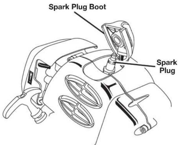
See Figure 18.
All model numbers included in this manual use a Champion RCJ4 spark plug. Use an exact replacement and replace annually.
- Remove the spark plug boot.
- Loosen the spark plug by turning it counterclockwise with a socket.
- Remove the spark plug.
- Hand thread the new spark plug, turning it clockwise.
- Tighten with a socket. (torque to 170 in.lb. minimum, 190 in.lb. maximum. Do not over-tighten).
CAUTION:
Be careful not to cross-thread the spark plug.
Cross-threading will seriously damage the product.
text_image
Spark Plug Boot Spark PlugFigure 18
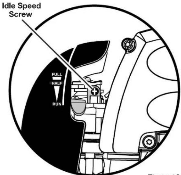
IDLE SPEED ADJUSTMENT
See Figure 19.
If the cutting attachment turns at idle, the idle speed screw needs adjusting on the engine. Turn the idle speed screw counterclockwise to reduce the idle RPM and stop the cutting attachment movement. If the cutting attachment still moves at idle speed, contact a service dealer for adjustment and discontinue use until the repair is made.

WARNING:
The cutting attachment should never turn at idle. Turn the idle speed screw counterclockwise to reduce the idle RPM and stop the cutting attachment, or contact a service dealer for adjustment and discontinue use until the repair is made. Serious personal injury may result from the cutting attachment turning at idle.
Storing the Product
Storing the product differs depending on the amount of time it will be in storage.
Note: If the product includes another attachment, place the storage cap on the end of the attachment shaft and hang it up to store.
To Store the Product Short Term:
Follow these steps to store the product short term.
- Clean all foreign material from the product.
- Store the product in a well-ventilated place that is inaccessible to children.
To Store the Product Long Term:
If you do not intend to use the product for more than one month, follow the storage procedures below.
Follow these steps to store the product long term.
- Drain all of the fuel from the tank into a container approved for gasoline.
- Run the engine until it stops.
- Clean all foreign material from the product.
- Store the product in a well-ventilated place that is inaccessible to children.
Note: Keep the product away from corrosive agents such as garden chemicals and de-icing salts.
Note: Abide by all federal and local regulations for the safe storage and handling of gasoline.
Transporting the Product
Follow these steps to transport the product.
- Drain the fuel mixture into a container that is approved for use with gasoline.
- Carry the product by the front handle.
- Secure the product in your vehicle or on a trailer.
text_image
Idle Speed Screw FULL HALF RUNFigure 19
text_image
Straight Shaft Cover Latches Knob Spool Curved Shaft Spring Hex Bolt Spring Head Latch OpeningFigure 20
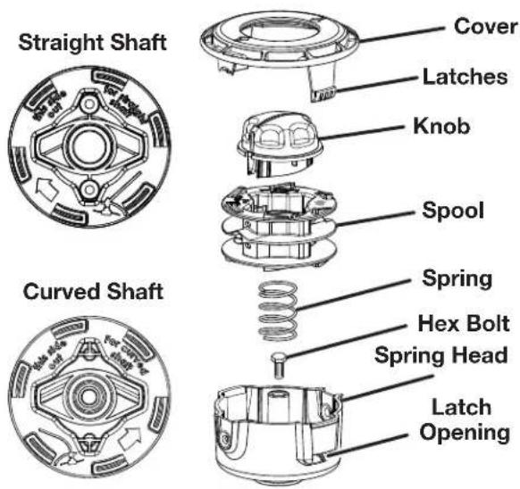
Installing Reel Easy String Head
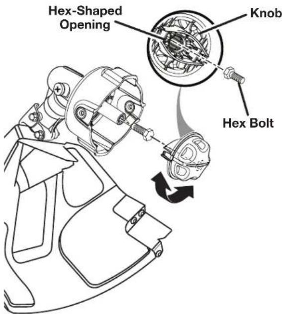
See Figures 20 - 21.
■ Stop the engine and disconnect the spark plug wire.
■ Open the Reel Easy string head by depressing the latches on each side. The contents of the string head are spring loaded, so keep your other hand over the string head cover while depressing the latches.
■ Remove the string head cover, knob, and spool and set aside.
■ Place the upper housing on the drive shaft. Make sure the string head is fully seated.
■ Install the hex bolt into the opening on the drive shaft and secure using the hex-shaped opening in the knob to tighten. Turn clockwise for curved shaft and counterclockwise for straight shaft to tighten.
Note: Only use the knob to tighten the bolt. The use of other tools may allow overtightening of the bolt, which could damage the string head.
If removed, replace the spring into the string head and push down to seat.
■ Reinstall the spool. For the 51954, the spool should be placed so “This side out for curved shaft” is visible. For the 51974, the spool should be placed so “This side out for straight shaft” is visible.
■ Replace the knob in the spool.
■ Replace the string head cover, aligning latches with openings in the string head. Press cover and string head together until both latches snap into openings securely.
■ Install line as described in the operation section of this manual.
text_image
Hex-Shaped Opening Knob Hex BoltFigure 21
Emissions Maintenance Schedule
Maintenance, replacement, or repair of the emission control device and systems may be performed by any non-road engine repair establishment or individual.
| Emission Part | Inspect before each use | Clean every 5 hours | Replace every 25 hours or yearly | Clean every 25 hours or yearly | Replace every 125 hours |
| Fuel Tank Assembly (Includes Fuel Lines, Fuel Cap, and Fuel Filter) | X | ||||
| Air Filter X | X | ||||
| Spark Arrester | X | ||||
| Spark Plug | X | ||||
| Muffler |
X
High Altitude Engine Operation:
Please have an authorized service center modify this engine if it is to be run above 2000 feet. Failure to do so may result in poor engine performance, spark plug fouling, hard starting, and increased emissions. Carburetor modification by an authorized service center will improve performance and allow that this engine meet the EPA (Environmental Protection Agency) and California ARB (Air Resources Board) emission standards. An engine modified for high altitudes can not be run at 2000 feet or lower. In doing so, the engine will overheat and cause serious engine damage. Please have an authorized service center restore high altitude modified engines to the original factory specification before operating below 2000 feet.
| Problem Possible Cause Solution | ||
| Engine will not start | 1. Switch set to the O (OFF) position.2. No spark3. No fuel4. Flooded engine5. Starter cord pulls harder now then when new | 1. Set switch to the I (ON) position.2. Remove the spark plug. Reattach the spark plug cap and lay the spark plug on the metal cylinder. Pull the starter cord and watch for a spark at the spark plug tip. If there is no spark, repeat the test with a new spark plug.3. Push primer bulb until the bulb is full of fuel. If the bulb does not fill, the primary fuel delivery system is blocked. If the primer bulb fills, the engine may be flooded. (See next item.)4. Remove the spark plug. Turn the product so that the spark plug hole is aimed at the ground.Make sure the choke lever is set to RUNand pull the starter cord 10 to 14 times. This clears excess fuel from the engine. Clean and reinstall the spark plug. With the trigger fully depressed, pull the starter cord 3 times. If the engine does not start, set the choke lever to FULL and follow normal starting instructions. If the engine still fails to start, repeat the procedure with a new spark plug.5. Contact an authorized service dealer. |
| Engine does not reach full speed and emits excessive smoke | 1. Check oil fuel mixture2. Air filter is dirty3. Spark arrestor screen is dirty | 1. Use fresh fuel and the correct 2-cycle oil mix.2. Clean the air filter.3. Clean the spark arrester. |
| Line will not advance when using automatic line lengthening | 1. Line welded to itself2. Not enough line on the spool3. Line worn too short4. Line tangled on spool5. Engine speed too slow | 1. Lubricate with silicone spray.2. Install more line.3. Pull line while alternately pressing down on and releasing the retaining cap.4. Remove line from spool and rewind.5. Advance line at full throttle. |
| Grass wraps around the trim-mer head assembly and the attachment shaft | 1. Cutting tall grass at ground level2. Operating the product at part throttle | 1. Cut tall grass from the top down.2. Operate the product at full throttle. |
| Oil drips from muffler | 1. Operating the product at part throttle2. Check oil/fuel mixture3. Air filter is dirty | 1. Operate the product at full throttle.2. Use fresh fuel and the correct 2-cycle oil mix.3. Clean the air filter. |

Count on it.
THIS PRODUCT IS MANUFACTURED UNDER LICENSE FROM THE TORO COMPANY BY TECHTRONIC INDUSTRIES NORTH AMERICA, INC.
Techtronic Industries north America, Inc. warrants to the original retail purchaser that this gas trimmer Product is free from defects in material and workmanship and agrees to repair or replace, at our option, any defective Product free of charge within these time periods from the date of purchase:
■ Three years for Gas Trimmer Products, if the Product is used for personal, family, or household use;
■ 90 days, if Gas Trimmer Products are used for any other purpose, such as commercial or rental.
■ Three years for emissions control systems on Gas Trimmer Products used for any purpose, as provided below.
Except as provided in the Emission Control Warranty Statement, this warranty extends to the original retail purchaser only and commences on the date of original retail purchase.
Instructions for Obtaining Warranty Service
Any part of the Product manufactured or supplied by Techtronic Industries North America, Inc. and found in the reasonable judgement of Techtronic Industries North America, Inc. to be defective in material or workmanship will be repaired or replaced by an authorized service dealer for this product without charge for parts and labor. To locate your nearest authorized service dealer for this product, contact us Toll free at 1-866-574-9242 (US) or 1-866-574-9243 (Canada).
The Product including any defective part must be returned to an Authorized Service Dealer for this product within the warranty period. The expense of delivering the Gas Trimmer Product to the service dealer for warranty work and the expense of returning it back to the owner after repair or replacement will be paid for by the owner. Techtronic Industries North America. Inc.'s responsibility in respect to claims is limited to making the required repairs or replacements and no claim of breach of warranty shall be cause for cancellation or rescission of the contract of sale of any Product. Proof of purchase will be required by the dealer to substantiate any warranty claim. All warranty work must be performed by a service dealer authorized by Techtronic Industries North America, Inc. to service this product.
This warranty does not cover any Gas Trimmer Product that has been subject to misuse, neglect, negligence, or accident, or that has been operated in any way contrary to the operating instructions as specified in the Operator's Manual. This warranty does not apply to any damage to the Gas Trimmer Product that is the result of improper maintenance or to any Gas Trimmer Product that has been altered or modified so as to adversely affect the products operation, performance or durability or that has been altered or modified so as to change its intended use. The warranty does not extend to repairs made necessary by normal wear or by the use of parts or accessories which are either incompatible with the Gas Trimmer Product or adversely affect its operation, performance or durability.
In addition, this warranty does not cover the following (except to the extent covered by the emissions control warranty set forth below):
A. Tune-ups - Spark Plugs, Carburetor Adjustments, Filters
B. Wear Items – Bump Knobs, Outer Spools, Cutting Lines, Inner Reels, Starter Pulley, Starter Ropes, Drive Belts, Tines, Felt Washers, Hitch Pins, Mulching Blades, Blower Fans, Blower and Vacuum Tubes, Vacuum Bag and Straps, Guide Bars, Saw Chains
Techtronic Industries North America, Inc. reserves the right to change or improve the design of any Gas Trimmer Product without assuming any obligation to modify any product previously manufactured.
ALL IMPLIED WARRANTIES ARE LIMITED IN DURATION TO THE STATED WARRANTY PERIOD. ACCORDINGLY, ANY SUCH IMPLIED WARRANTIES INCLUDING MERCHANTABILITY, FITNESS FOR A PARTICULAR PURPOSE, OR OTHERWISE, ARE DISCLAIMED IN THEIR ENTIRETY AFTER THE EXPIRATION OF THE APPROPRIATE THREE-YEAR OR NINETY DAY WARRANTY PERIOD. TECHTRONIC INDUSTRIES NORTH AMERICA, INC.'S OBLIGATION UNDER THIS WARRANTY IS STRICTLY AND EXCLUSIVELY LIMITED TO THE REPAIR OR REPLACEMENT OF DEFECTIVE PARTS AND TECHTRONIC INDUSTRIES NORTH AMERICA, INC. DOES NOT ASSUME OR AUTHORIZE ANYONE TO ASSUME FOR THEM ANY OTHER OBLIGATION. SOME STATES DO NOT ALLOW LIMITATIONS ON HOW LONG AN IMPLIED WARRANTY LASTS, SO THE ABOVE LIMITATION MAY NOT APPLY TO YOU.
TECHTRONIC INDUSTRIES NORTH AMERICA, INC. ASSUMES NO RESPONSIBILITY FOR INCIDENTAL, CONSEQUENTIAL, OR OTHER DAMAGES INCLUDING, BUT NOT LIMITED TO EXPENSE OF RETURNING THE GAS TRIMMER PRODUCT TO A GAS TRIMMER AUTHORIZED SERVICE DEALER AND EXPENSE OF DELIVERING IT BACK TO THE OWNER, MECHANIC'S TRAVEL TIME, TELEPHONE, OR TELEGRAM CHARGES, RENTAL OF A LIKE PRODUCT DURING THE TIME WARRANTY SERVICE IS BEING PERFORMED, TRAVEL, LOSS, OR DAMAGE TO PERSONAL PROPERTY, LOSS OF REVENUE, LOSS OF USE OF THE PRODUCT, LOSS OF TIME, OR INCONVENIENCE. SOME STATES DO NOT ALLOW THE EXCLUSION OR LIMITATION OF INCIDENTAL OR CONSEQUENTIAL DAMAGES, SO THE ABOVE LIMITATION OR EXCLUSION MAY NOT APPLY TO YOU.
This warranty gives you specific legal rights, and you may also have other rights, which vary, from state to state.
THE FOLLOWING CALIFORNIA AIR RESOURCES BOARD (CARB) STATEMENT ONLY APPLIES TO MODEL NUMBERS REQUIRED TO MEET THE CARB REQUIREMENTS.
TECHTRONIC INDUSTRIES NORTH AMERICA, INC., LIMITED WARRANTY STATEMENT FOR FEDERAL AND CALIFORNIA EMISSION CONTROL SYSTEMS NON-ROAD AND SMALL OFF-ROAD ENGINES YOUR WARRANTY RIGHTS AND OBLIGATIONS
The U.S. Environmental Protection Agency (EPA), the California Air Resources Board (CARB), and Techtronic Industries North America, Inc., are pleased to explain the Emissions Control System Warranty on your 2010 model year non-road or small off-road engine. In California, new equipment that uses small off-road engines must be designed, built, and equipped to meet the state's stringent anti-smog standards. In other states, new 2010 and later model year non-road engines must be designed, built, and equipped at the time of sale to meet the U.S. EPA regulations for small non-road engines. The non-road engine must be free from defects in materials and workmanship which cause it to fail to conform with U.S. EPA standards for the first three years of engine use from the date of sale to the ultimate purchaser. Techtronic Industries North America, Inc., must warrant the emission control system on your non-road or small off-road engine for the period of time listed above provided there has been no abuse, neglect, or improper maintenance of your non-road or small off-road engine.
Your emission control system may include parts such as the carburetor or fuel injection system, the ignition system, catalytic converters, fuel tanks, valves, filters, clamps, connectors, and other associated components. Also included may be hoses, belts and connectors, and other emission-related assemblies.
Where a warrantable condition exists, Techtronic Industries North America, Inc., will repair your non-road or small off-road engine at no cost to you, including diagnosis, parts, and labor performed at an authorized service center for Torö brand outdoor products.
MANUFACTURER'S WARRANTY COVERAGE:
This product's emissions control system is warranted for three years. If any emission-related part on your engine is defective, the part will be repaired or replaced by Techtronic Industries North America, Inc., free of charge.
OWNER'S WARRANTY RESPONSIBILITIES
(a) As the non-road or small off-road engine owner, you are responsible for the performance of the required maintenance listed in your operator's manual. Techtronic Industries North America, Inc., recommends that you retain all receipts covering maintenance on your non-road or small off-road engine, but Techtronic Industries North America, Inc., cannot deny warranty solely for the lack of receipts or for your failure to ensure the performance of all scheduled maintenance. Any replacement part or service that is equivalent in performance and durability may be used in non-warranty maintenance or repairs, and shall not reduce the warranty obligations of Techtronic Industries North America, Inc., (b) As the non-road or small off-road engine owner, you should be aware, however, that Techtronic Industries North America, Inc., may deny you warranty coverage if your non-road or small off-road engine or a part has failed due to abuse, neglect, improper maintenance, or unapproved modifications.
(c) You are responsible for presenting your non-road or small off-road engine to an authorized service dealer as soon as a problem exists. The warranty repairs should be completed in a reasonable amount of time, not to exceed 30 days.
If you have any questions regarding your warranty rights and responsibilities, you should contact a Techtronic Industries North America, Inc., Customer Representative at 1-866-574-9242 (US) or 1-866-574-9243 (Canada).
DEFECT WARRANTY COVERAGE REQUIREMENTS:
(a) The warranty period begins on the date the engine or equipment is delivered to an ultimate purchaser.
(b) General Emissions Warranty Coverage. Techtronic Industries North America, Inc., warrants to the ultimate purchaser and each subsequent purchaser that your non-road or small off-road engine is designed, built, and equipped at the time of sale to conform with all applicable regulations adopted by the California Air Resources Board or the United States Environmental Protection Agency; and that it is free from defects in materials and workmanship which cause the engine to fail to conform with applicable regulations for a period of three years from the date the non-road or small off-road engine is purchased by the initial purchaser.
(c) The warranty on emissions-related parts will be interpreted as follows: Any warranted part that is not scheduled for replacement as required in the Emissions Maintenance Schedule and Warranty Parts List set forth below is warranted for three years. If any such part (including any part that is scheduled only for regular inspection) fails during the period of warranty coverage, it will be repaired or replaced at any Authorized Service Center at no charge. Any such part repaired or replaced under warranty will be warranted for the remaining warranty period. A statement to the effect of “repair or replace as necessary” would not reduce the period of warranty coverage. Any warranted part that is scheduled for replacement as required maintenance in the Emissions Maintenance Schedule and Warranty Parts List is warranted for the period of time prior to the first scheduled replacement point for that part. Any such part repaired or replaced under warranty is warranted for the remainder of the period prior to the first scheduled replacement point, and will be repaired or replaced at any Authorized Service Center for no charge until that replacement point is reached.
Techtronic Industries North America, Inc., shall remedy warranty defects at any authorized Authorized Service Center, including any distribution center that may be franchised to service the subject engines. Any diagnostic work done at a Authorized Service Center shall be free of charge to the owner if such work determines that a warranted part is defective. Any manufacturer-approved or equivalent replacement part may be used for any warranty maintenance or repairs on emission-related parts, and must be provided free of charge to the owner if the part is still under warranty. Techtronic Industries North America, Inc., is liable for damages to other engine components caused by the failure of a warranted part still under warranty.
Add-on or modified parts that are not exempted by the California Air Resource Board may not be used. The use of any non-exempted add-on or modified parts will be grounds for disallowing a warranty claim. Techtronic Industries North America, Inc., will not be liable to warrant failures of warranted parts caused by the use of a non-exempted add-on or modified part.
The California Air Resources Board's Emission Warranty Parts List specifically defines the emission-related warranted parts. (EPA's regulations do not include a parts list, but the EPA considers emission-related warranted parts to include all the parts listed below.) Techtronic Industries North America, Inc., will provide any documents that describe its warranty procedures or policies within five days upon request by the California Air Resources Board.
EMISSIONS PARTS LIST
Emissions parts vary from product to product. Your emissions control system warranty applies to any of the following components that may be included on your product:
(1) Fuel Metering System
(i) Carburetor and internal parts (and/or pressure regulator or fuel injection system).
(ii) Air/fuel ratio feedback and control system.
(iii) Cold start enrichment system.
(iv) Fuel Tank.
(2) Air Induction System
(i) Controlled hot air intake system.
(ii) Intake manifold.
(iii) Air filter.
(3) Ignition System
(i) Spark Plugs.
(ii) Magneto or electronic ignition system.
(iii) Spark advance/retard system.
(4) Exhaust Gas Recirculation (EGR) System
(i) EGR valve body and carburetor spacer, if applicable.
(ii) EGR rate feedback and control system.
(5) Air Injection System
(i) Air pump or pulse valve.
(ii) Valves affecting distribution of flow.
(iii) Distribution manifold.
(6) Catalyst or Thermal Reactor System
(i) Catalytic converter.
(ii) Thermal reactor.
(iii) Exhaust manifold.
(7) Particulate Controls
(i) Traps, filters, precipitators, and any other device used to capture particulate emissions.
(8) Miscellaneous Items Used in Above Systems
(i) Electronic controls.
(ii) Vacuum, temperature, and time sensitive valves and switches.
(iii) Hoses, belts, connectors, and assemblies.
Techtronic Industries North America, Inc., will furnish with each new engine written instructions for its maintenance and use by the owner.
THIS PRODUCT WAS MANUFACTURED WITH A CATALYST MUFFLER
Congratulations! You have made an investment toward protecting the environment. In order to maintain this product's original emission level, please refer to the maintenance section below.
EMISSIONS MAINTENANCE SCHEDULE AND WARRANTED PARTS LIST
| Emissions Parts | Inspect Before | Clean Every | Replace | Clean Every | Replace Every | Replace |
| Every Each Use or Yearly | 5 Hours | Every 25 Hours | 25 Hours | 50 Hours | Every 125 Hours |
CATALYTIC MUFFLER ASSEMBLY....X
AIR FILTER ASSY
includes:
Filter ....X....X
SPARK SCREEN ....X
CARBURETOR ASSY
includes:
Heat Dam
Gaskets
FUEL TANK ASSY
includes:
Fuel Lines....X
Fuel Cap....X
Fuel Filter
IGNITION ASSY
includes:
Spark Plug ....X
ALL EMISSIONS RELATED PARTS ARE WARRANTED FOR THREE YEARS OR FOR THE PERIOD OF TIME PRIOR TO THE PARTS FIRST SCHEDULED REPLACEMENT WHICHEVER COMES FIRST.

text_image
NEED HELP ? CALL 1-866-574-9242 (US) or 1-866-574-9243 (Canada)CALL US FIRST
For any questions about operating or maintaining your product, call the Toro® Help Line!
Your product has been fully tested prior to shipment to ensure your complete satisfaction.
Notes
TORO®
Customer Service Information
If your product requires service or maintenance, contact your nearest authorized service dealer. To locate your nearest authorized service dealer for this product, contact us toll free at 1-866-574-9242 (US) or 1-866-574-9243 (Canada).
This product is manufactured under license from The Toro Company by Techtronic Industries North America, Inc.
Techtronic Industries North America, Inc.
1428 Pearman Dairy Rd.
Anderson, SC 29621
USA
text_image
I O MARCHE ARRÊTtext_image
! Handle Position 30' 15m
text_image
!1 l to 20 cc (20 ml)
Before inspecting, cleaning, or servicing the machine, shut off engine, wait for all moving parts to stop, and disconnect spark plug wire and move it away from spark plug. Failure to follow these instructions can result in serious personal injury or property damage.
Nettoyage
Techtronic Industries North America, Inc.
Part No. 940686064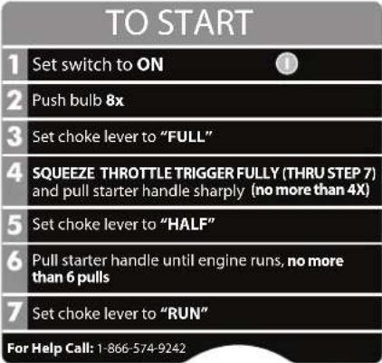 | Part No. 940864001 ENC. APAG. ENC. APAG. |
Part No. 940657034 | Part No. 940230132 |
Part No. 940865001 | Part No. 940627020 |
Características
natural_image
Diagram of a car's steering wheel and dashboard (no text or labels)natural_image
Diagram of a car's steering wheel and dashboard (no text or symbols)text_image
InterruptorGatillo del
acelerador
Figura 8
Techtronic Industries North America, Inc.
1428 Pearman Dairy Rd.
Anderson, SC 29621
USA
CE PRODUIT A ÉTÉ ÉQUIPÉ EN USINE D'UN CONVERTISSEUR CATALYTIQUE
Techtronic Industries North America, Inc.
1428 Pearman Dairy Rd.
Anderson, SC 29621
États-Unis