5000 series XC5141 - Vacuum Cleaner PHILIPS - Free user manual and instructions

Find the device manual for free 5000 series XC5141 PHILIPS in PDF.

PHILIPS 5000 series XC5141 - Vacuum Cleaner
📄 999 pages English EN Download 💬 AI Question 10 questions ⚙️ Specs
Notice PHILIPS 5000 series XC5141 - page 5
Pick your language and provide your email: we'll send you a specifically translated version.
Product type Cordless stick vacuum with washing function
Brand Philips
Model 5000 series XC5141
Power supply Rechargeable Li-Ion battery
Charging time Approximately 4 hours
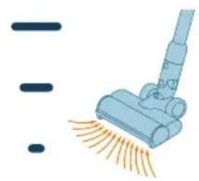
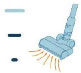
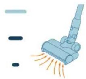
Power settings 3 modes: eco, normal, turbo
Water tank capacity 300 ml
Filter type Washable foam filter
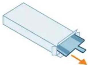
Included accessories Main nozzle, Turbo mini brush (XC5141), crevice tool, combination tool, water tank, microfiber wash pad
Washing function Yes, for sealed hard floors
Filter maintenance Monthly cleaning, replacement every 6 months
Water tank maintenance Monthly descaling recommended
Safety Automatic shut-off in case of blockage, error codes
Spare parts available Filter XV1651, wash pad XV1630
Operating temperature 0 °C to 35 °C (charging: 10 °C to 35 °C)

Frequently Asked Questions - 5000 series XC5141 PHILIPS

How to charge my Philips 5000 series XC5141 vacuum cleaner?
Place the appliance on the wall mount or plug the adapter directly into the hand vacuum. Charging takes approximately 4 hours. The temperature must be between 10 °C and 35 °C.
What to do if the screen displays error code E2?
Error code E2 indicates that the appliance is operating outside its temperature range. Use and store the appliance between 0 °C and 35 °C and charge between 10 °C and 35 °C.
How to clean my vacuum cleaner's filter?
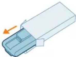
Remove the foam filter from its housing, tap it to remove dust, rinse it under cold water, squeeze it out, and let it dry for 24 hours before reinstalling. Clean it at least once a month.
Can the vacuum be used to wash carpets?
No, the water tank is only for sealed hard floors. For carpets, use dry suction mode.
How to replace the main nozzle brush?
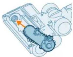
Hold down the button on the side of the nozzle, remove the brush, clean it, then put it back until you hear a "click".
What does error code i4 on the screen mean?
Code i4 indicates that the brush is blocked or an object obstructs the ventilation. Turn off the appliance, clean the brush, and remove the obstruction.
How much water to put in the tank?
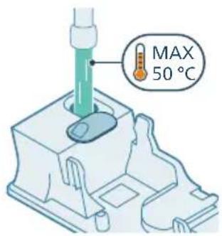
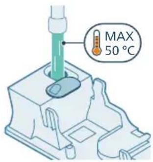
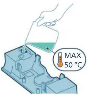
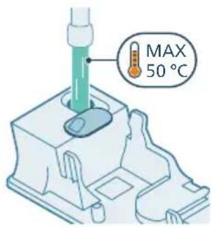
Fill the tank with water at a maximum of 50 °C up to the capacity of 300 ml. Add a few drops of liquid cleaner if desired.
How to descale the water tank?
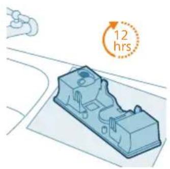
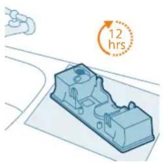
Pour descaling solution into the tank, add water, close and shake. Let sit for 12 hours, then rinse thoroughly.
Where to buy spare parts?
Visit www.philips.com/parts-and-accessories or contact your Philips dealer. References: filter XV1651, wash pad XV1630.
How to empty the dustbin?
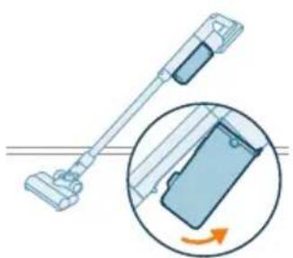
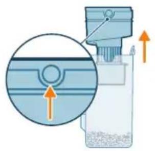
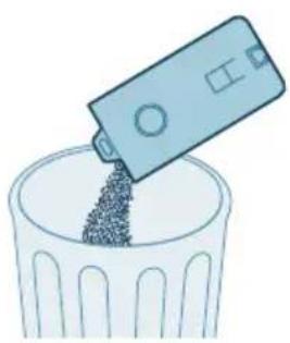
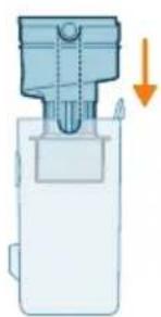
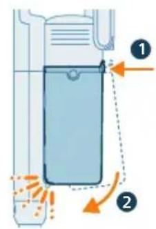
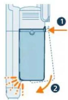
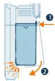
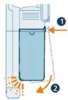
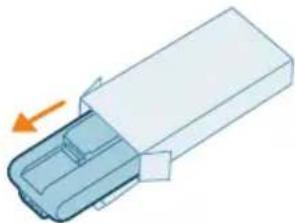
Turn off the appliance, tilt it 45°, press the unlock button to remove the bin, lift the cyclone, empty the bin, then reassemble everything.

User questions about 5000 series XC5141 PHILIPS

0 question about this device. Answer the ones you know or ask your own.

Ask a new question about this device

Your email remains private: it is only used to notify you if someone answers your question.

No questions yet. Be the first to ask one.

Download the instructions for your Vacuum Cleaner in PDF format for free! Find your manual 5000 series XC5141 - PHILIPS and take your electronic device back in hand. On this page are published all the documents necessary for the use of your device. 5000 series XC5141 by PHILIPS.

USER MANUAL 5000 series XC5141 PHILIPS

* = 0-9, representing different colors
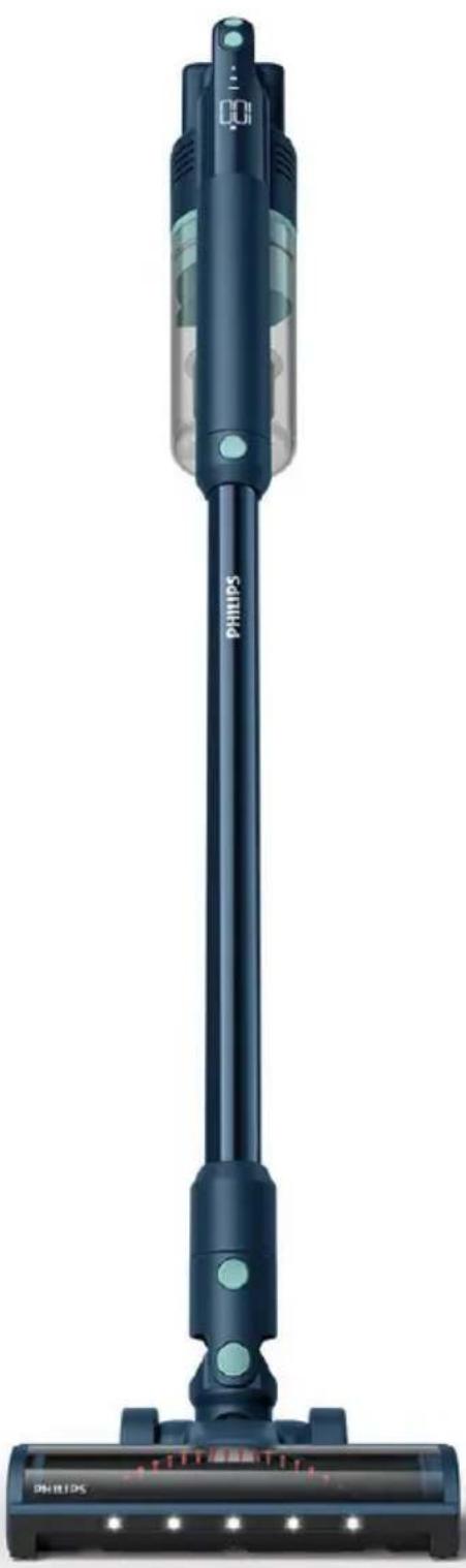
Exterior view of a Philips vacuum cleaner (no text or symbols on body)

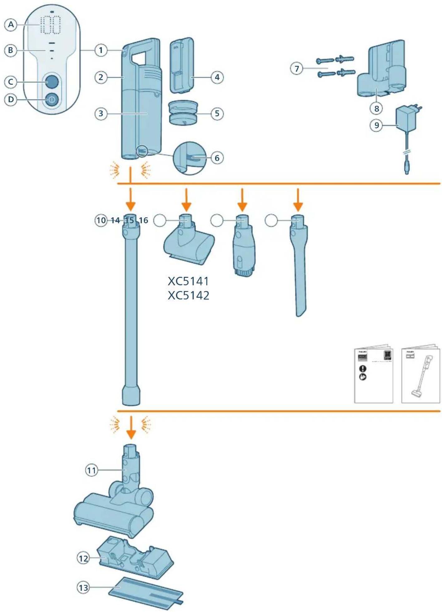
A B C D 1 2 3 4 5 6 7 8 9 10 14 15 16 XC5141 XC5142 11 12 13

English 4

Bahasa Indonesia 31

Bahasa Melayu 58

Czech 85

Montenegrin 112

Danish 139

German 166

Estonian 193

Spanish 220

French 247

Croatian 274

Italian 301

Latvian 328

Lithuanian 355

Magyar 382

Nederlands 409

Norsk 436

Polski 463

Português 490

General description 4

Before first use 5

Installing the wall mount 5

Preparing for use 6

Using the appliance 7

Assembling the appliance 7

Vacuuming soft and hard floors 8

Vacuuming while mopping hard floors 9

Versatile usage and accessories 12

Using the nozzle 12

Using the Mini TurboBrush 12

Using the crevice tool 13

Using the combination tool 13

After use – Maintenance 14

Frequent maintenance after each cleaning cycle ____ 14

Dust bucket maintenance 14

Aqua tank maintenance 15

Periodic maintenance intermittently 17

Dust management system maintenance 17

Nozzle maintenance 19

Mini TurboBrush maintenance (XC5141 and XC5142 only) ____ 21

Aqua tank maintenance 21

Replacement 23

User interface signals and their meaning 24

Troubleshooting 26

Dry cleaning 26

When using the Vacuum and Mop Nozzle 29

Introduction

Thank you for buying this product! To fully benefit from the support that we offer, register your product at www.philips.com/support.

General description

1 Control panel

a Percentage of battery level

b Power level indicators

c Power selection button

d On/off button

2 Handheld

3 Dust bucket

4 Battery

5 Filter

6 Dust bucket release button

7 Screw set

8 Wall mount 9 Adapter 10 Tube 11 Nozzle 12 Aqua tank 13 Microfiber mopping pad 14 Mini TurboBrush (XC5141, XC5142 only) 15 Combination tool 16 Crevice tool

Before first use

Installing the wall mount
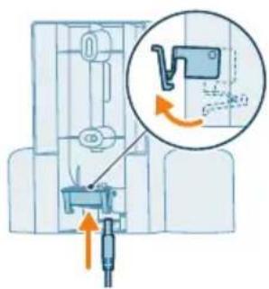
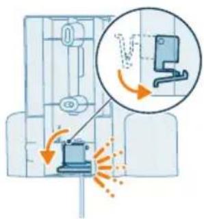
Diagram showing mechanical assembly with labeled parts and directional arrows indicating motion or movement

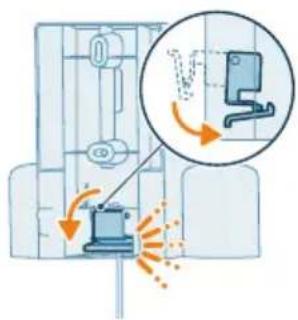
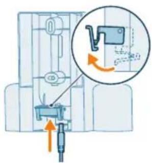
1 Invert the wall mount and unlatch the lever. Insert the charging port, ensuring the metal part is visible and pointing upright on the front side of the wall mount.
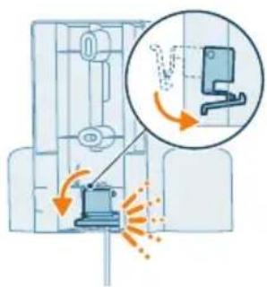
Diagram of a door with a device emitting heat and airflow, showing no text or symbols

2 Close the lever. Make sure the lever is locked in place with a "CLICK" sound.
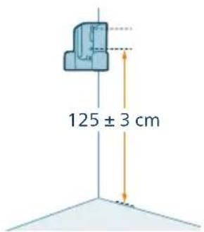
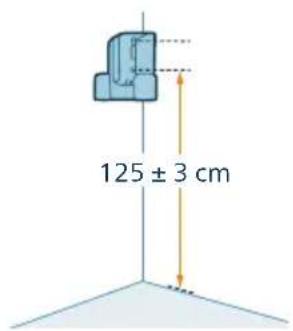
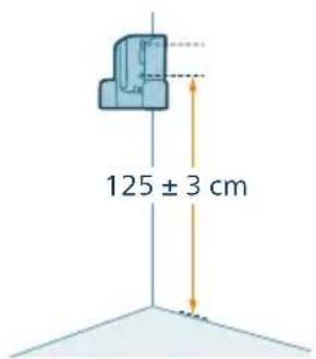
125 ± 3 cm

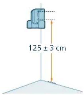
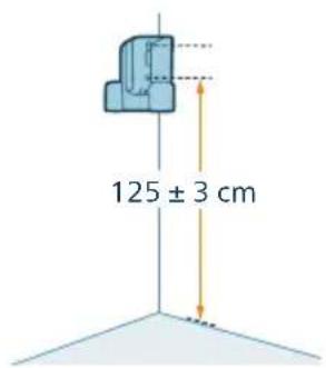
3 Securely affix the wall mount to your preferred position on the wall, ensuring that the lowest mounting screw holes are approximately 125 cm from the floor.

Caution: Be careful when you drill holes in the wall to fasten the wall mount, to avoid the risk of electric shock.
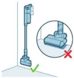
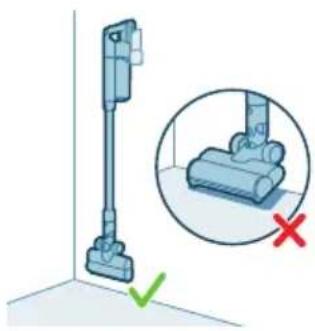
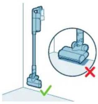
Illustration of a vacuum cleaner next to a close-up view of the device (no text or symbols present)

Note: Verify that the placement of the wall mount allows the entire appliance to hang on the wall without the nozzle coming into contact with the floor.
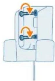
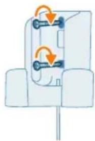
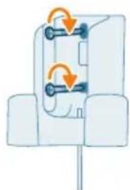
Diagram of a mechanical or electrical component with two rotating arms and directional arrows indicating motion (no text or symbols)

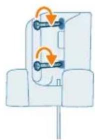
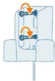
4 Once you have determined the optimal position and height for storing and charging your appliance, firmly tighten the screws to secure the wall mount in place.

Preparing for use
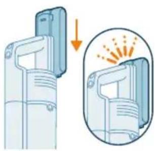
Illustration of a device with a magnified view showing internal components and heat distribution (no text or symbols)

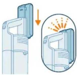
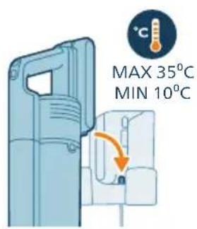
The appliance is equipped with a Li-Ion battery. Charging from empty to full takes about 4 hours.

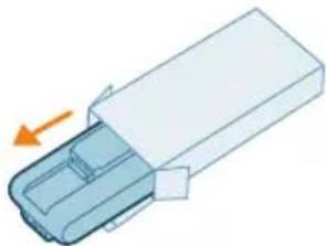
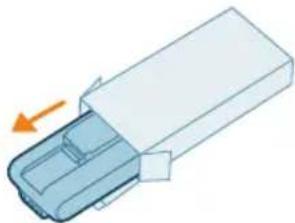
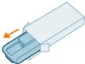
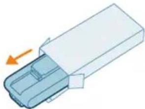
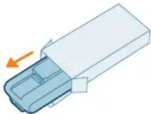
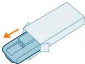
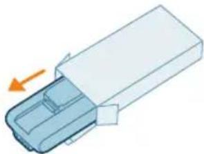
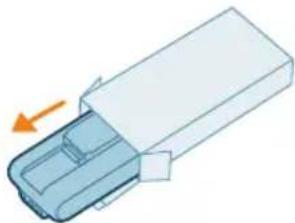
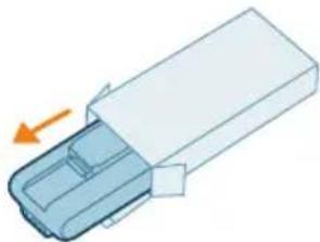
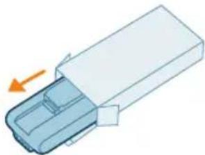
1 Attach the battery pack to the main body of the appliance, ensuring a secure connection that's confirmed with a "CLICK" sound.
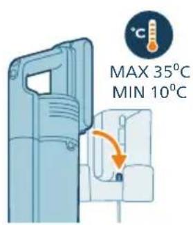
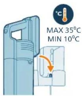
MAX 35°C MIN 10°C

2 Charge your appliance by placing it onto the assembled wall mount.

Warning: Charge the appliance at a temperature above 10 °C and below 35 °C.
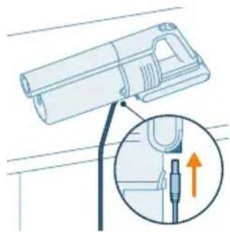
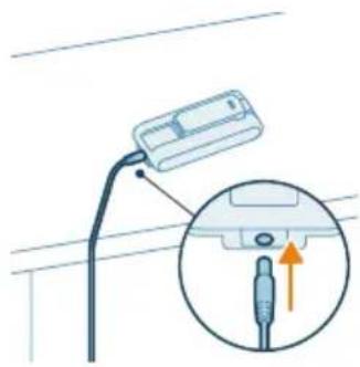
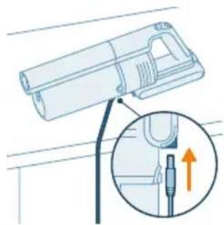
Technical illustration of a mechanical device with an inset showing a pin inserted into a cable (no text or symbols present)

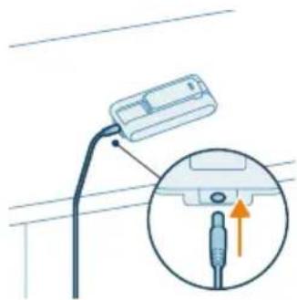
Note: You can also place the handheld on a level and stable surface, and directly connect the charging cable to the appliance.
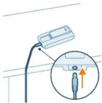
Diagram showing a cable with a connector and an inset magnified view of the plug (no text or symbols)

Note: Another option is to place the battery on a level and stable surface, and directly connect the charging cable to the battery.

graph TD A["Start State"] --> B["4 hrs"] B --> C["End State"]

3 The appliance is designed to reach a full charge within 4 hours. You can monitor the charging progress on the screen. When the appliance is fully charged, the value 100% lights up on the screen. After a few seconds, the display will turn off.

Using the appliance

Assembling the appliance
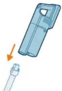
Illustration of a medical device with a magnified view showing internal components (no text or symbols)

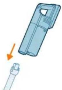
1 Attach the handheld to the tube. Confirm the attachment with a "CLICK" sound.
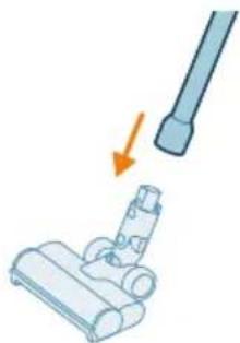
Illustration of a hand holding a cylindrical object with an arrow pointing to it, next to a mechanical component (no text or symbols present)

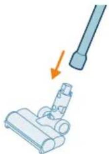
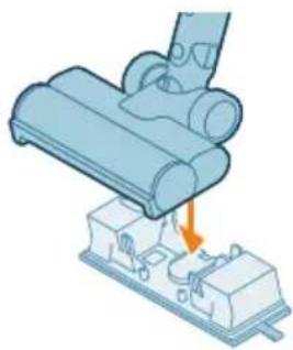
2 Attach the tube to the nozzle. Confirm the attachment with a "CLICK" sound.

Vacuuming soft and hard floors
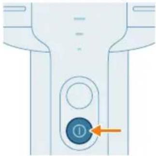
Diagram of a device control panel with a blue button labeled '①' and an orange arrow pointing to it (no text or symbols beyond the label)

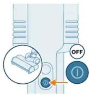
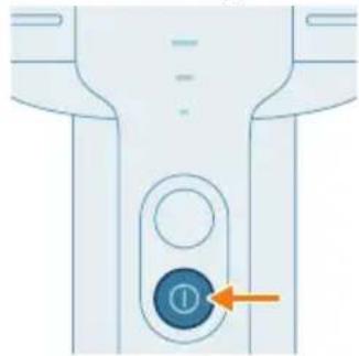
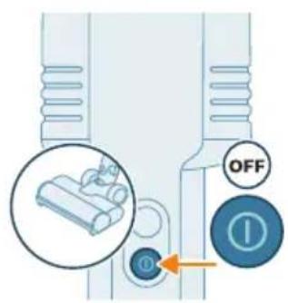
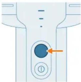
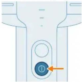
1 Press the on/off button to switch on the appliance.

Note: To switch off the appliance, press the on/off button again.
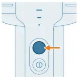
Diagram of a device control panel with an orange arrow pointing to a circular button (no text or symbols)

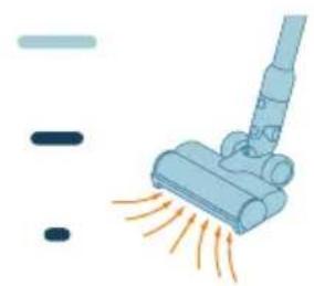
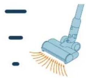
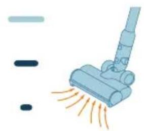
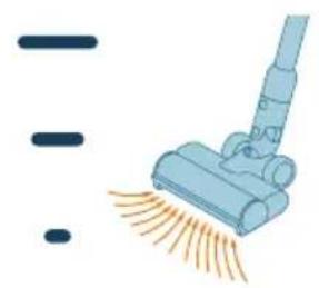
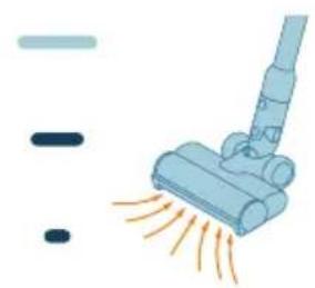
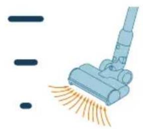
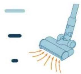
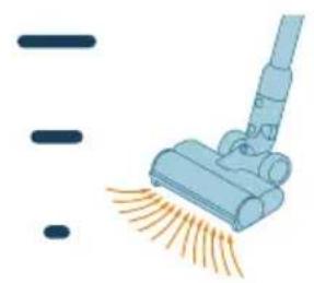
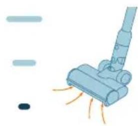
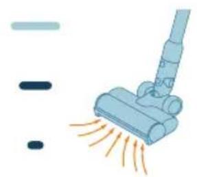
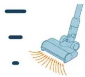
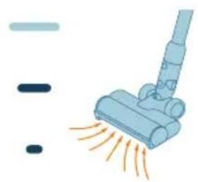
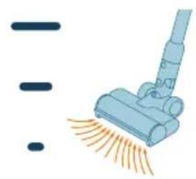
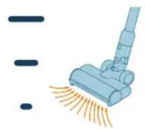
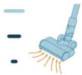
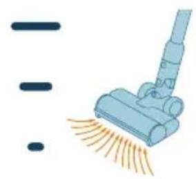
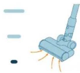
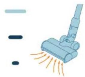
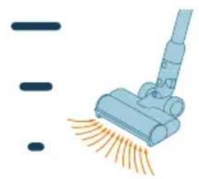
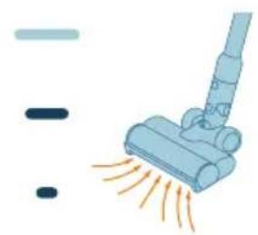
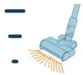
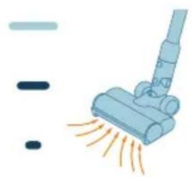
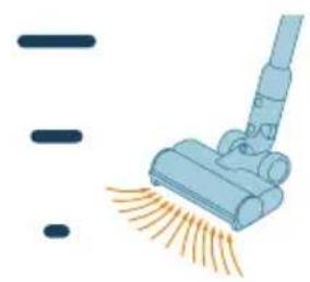
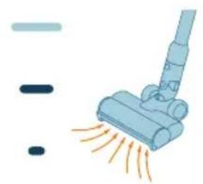
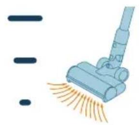
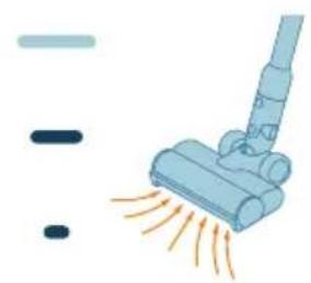
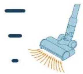
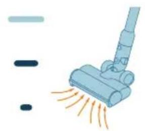
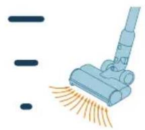
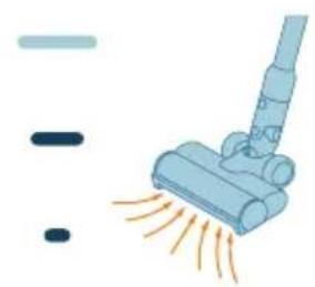
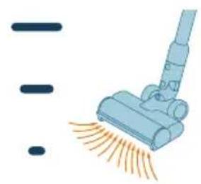
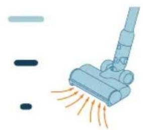
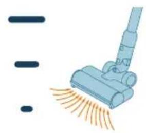
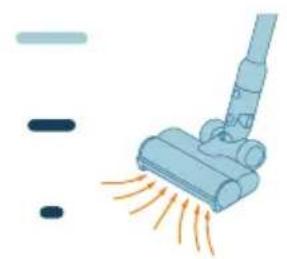
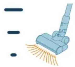
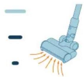
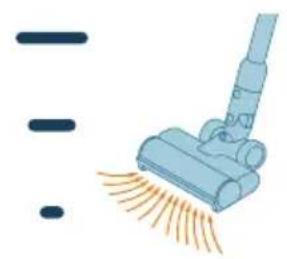
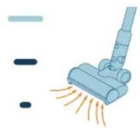
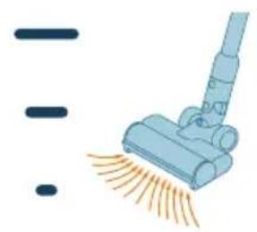
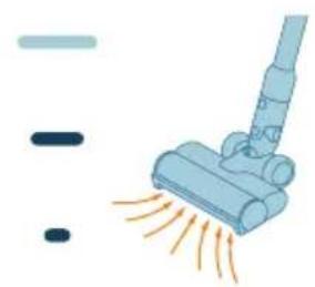
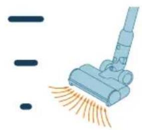
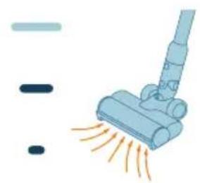
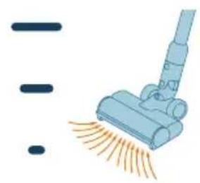
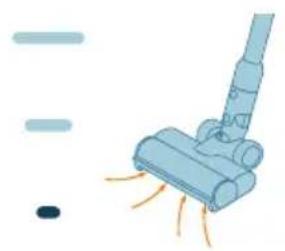
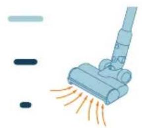
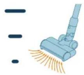
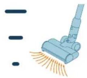
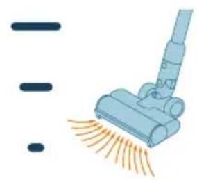
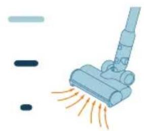
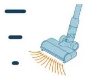
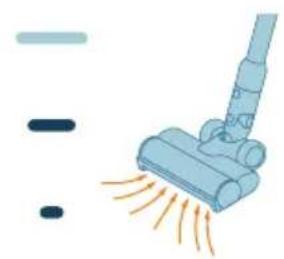
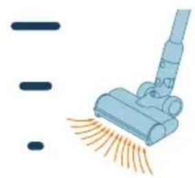
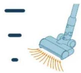
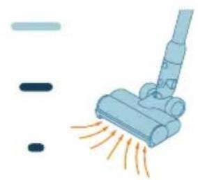
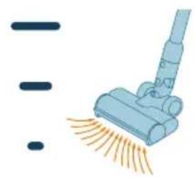
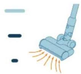
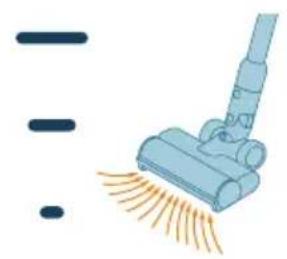
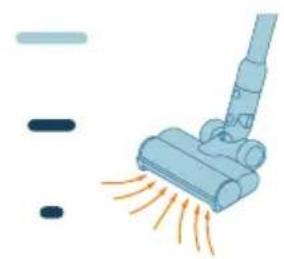
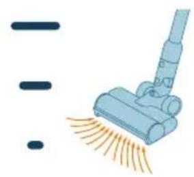
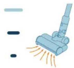
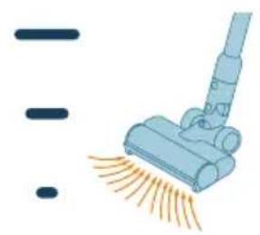
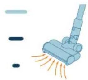
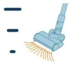
2 Use the power selection button to toggle through three different power settings: eco mode, normal mode, turbo mode.

Eco Normal Turbo
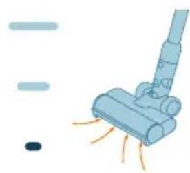
Illustration of a blue vacuum cleaner emitting exhaust smoke, with no text or symbols present.

Illustration of a vacuum cleaner emitting exhaust smoke, with no text or symbols present.

Illustration of a blue vacuum cleaner emitting orange spray, with no text or symbols present.

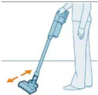
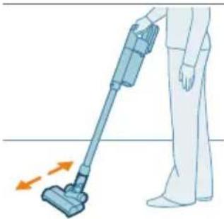
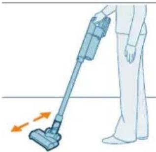
Illustration of a person using a vacuum cleaner to lift a person's legs, with no text or symbols present.

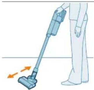
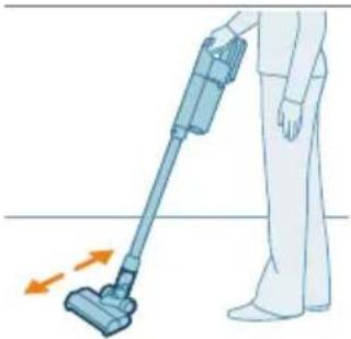
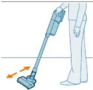
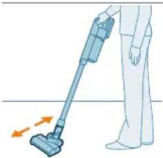
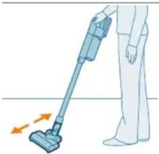
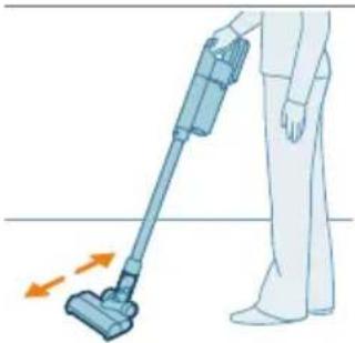
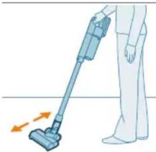
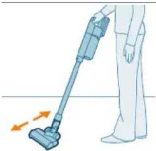
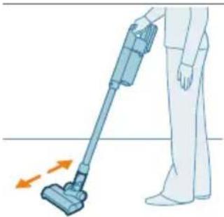
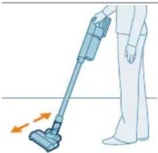
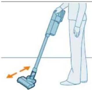
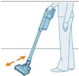
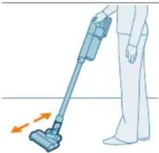
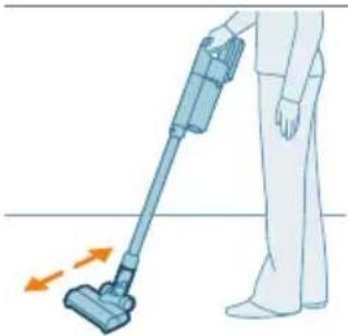
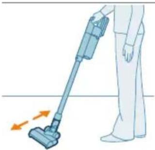
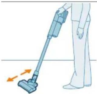
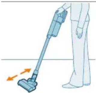
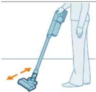
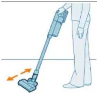
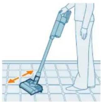
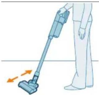
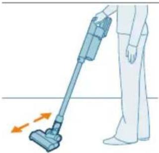
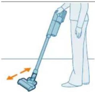
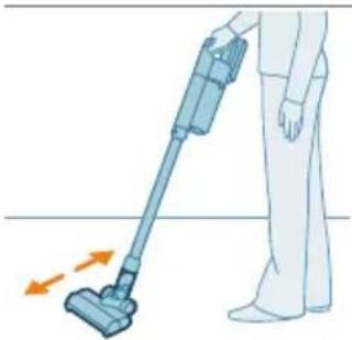
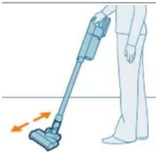
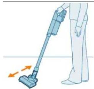
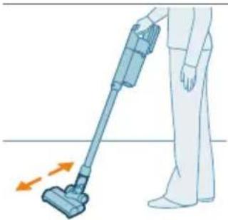
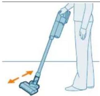
3 You can clean on hard or soft floors with the vacuum cleaner.
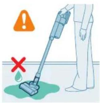
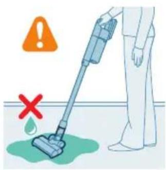
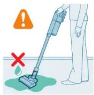
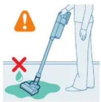
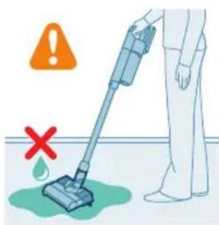
Safety warning illustration showing a person using a vacuum cleaner with a red 'X' indicating failure or absence.

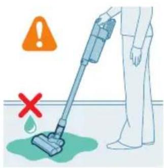
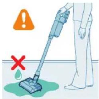
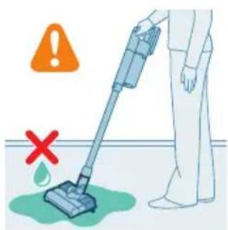
Warning: Do not vacuum up water or other liquids.
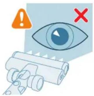
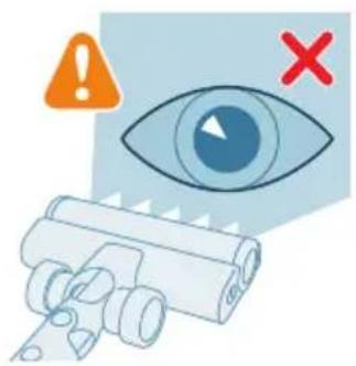
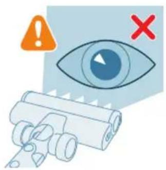
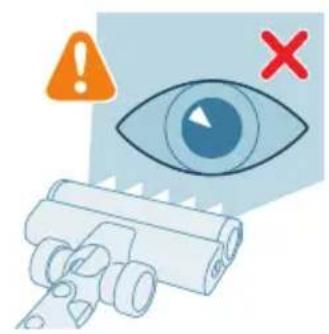
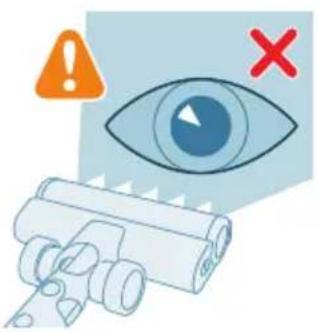
Illustration of a human eye with warning symbols, with no text or labels.

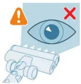
Caution: Do not look directly into the illuminated LEDs or point the LEDs at someone's eyes. The LED light is very bright.

Vacuuming while mopping hard floors

Caution: Only use the aqua tank on hard floors with a water-resistant top coat (such as linoleum, enameled tiles and varnished parquet) and stone floors (such as marble). If your floor has not been treated to make it water-resistant, check with the manufacturer if you can use water to clean it. Do not use the aqua tank on hard floors of which the water-resistant top coat is damaged.

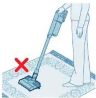
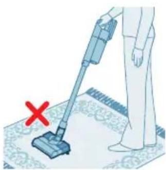
Note: Do not use the aqua tank to clean carpets.

Note: Do not move the appliance with aqua tank assembled sideways, as this leaves water traces. Only move forwards and backwards.

1 Pre-wet the microfiber mopping pad with water before use.
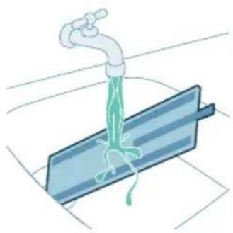
Illustration of a faucet spraying water onto a blue surface, with no text or symbols.

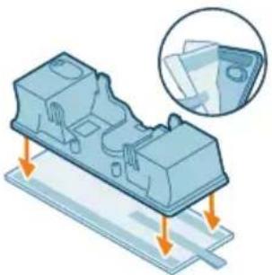
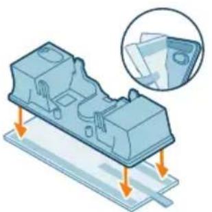
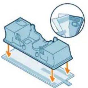
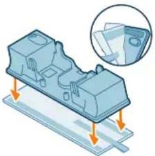
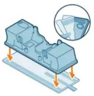
3D illustration of a mechanical component with arrows indicating assembly or movement, and a magnified inset showing a close-up of a sheet of paper, with no text or symbols present.

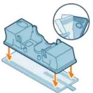
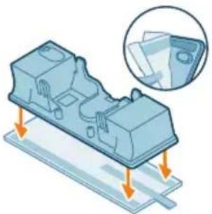
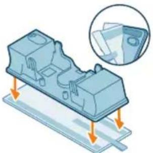
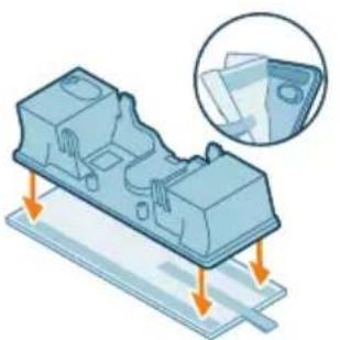
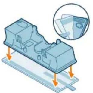
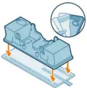
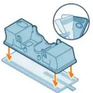
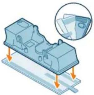
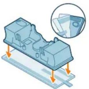
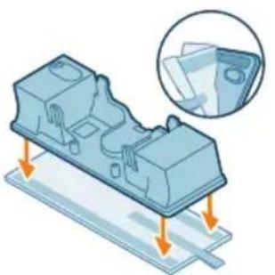
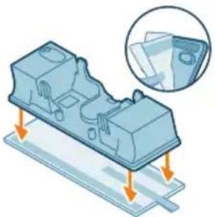
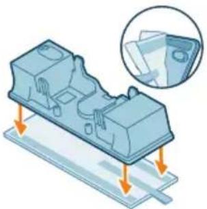
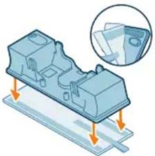
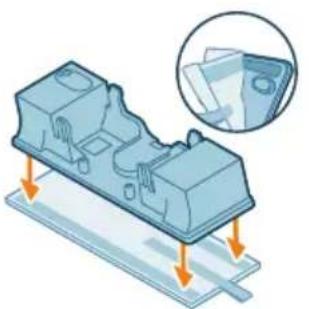
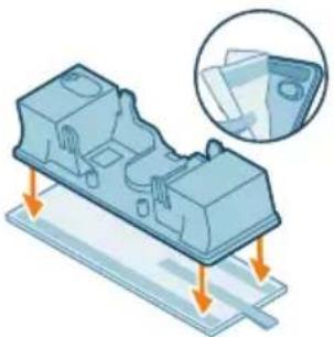
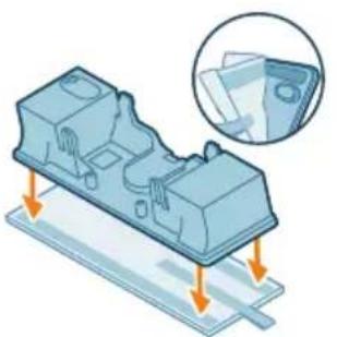
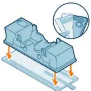
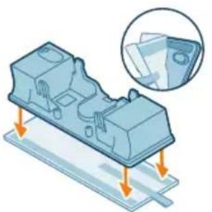
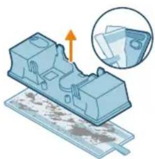
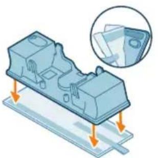
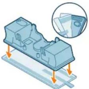
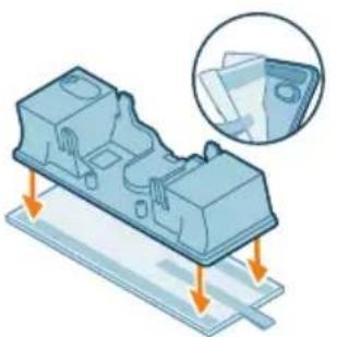
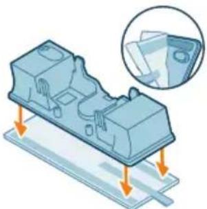
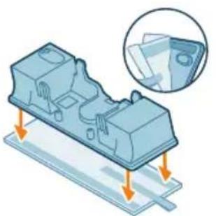
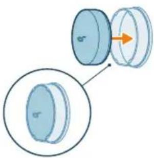
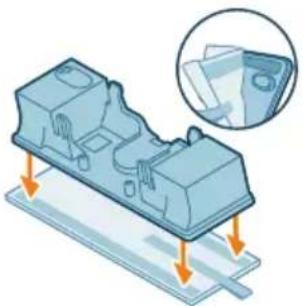
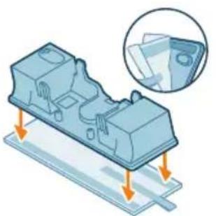
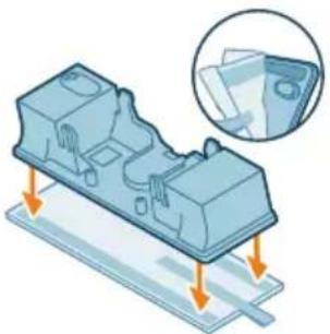
2 Secure the microfiber mopping pad underneath the aqua tank. Align the velcro straps under the aqua tank and behind the cloth.
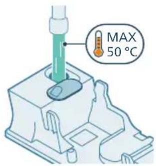
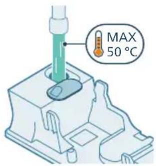
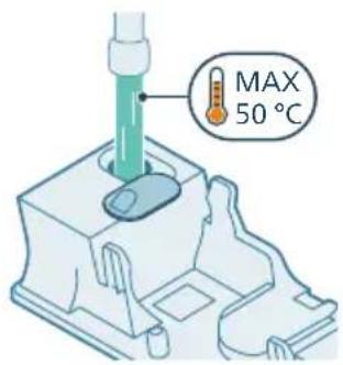
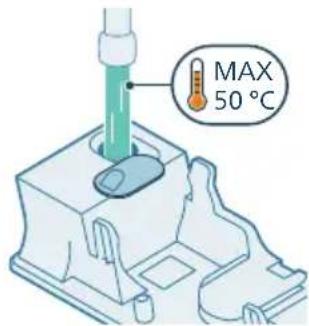
MAX 50 °C

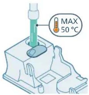
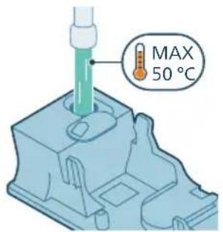
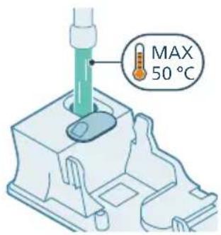
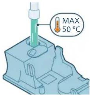
3 Open the rubber cap on top of the tank. Fill the tank with water, ensuring the water temperature does not exceed 50 °C.
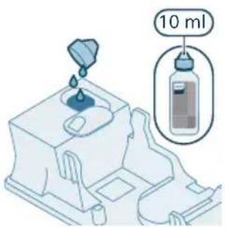
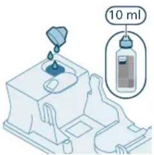
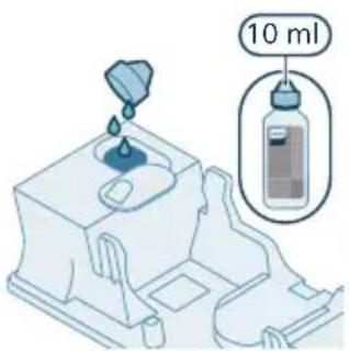
10 ml

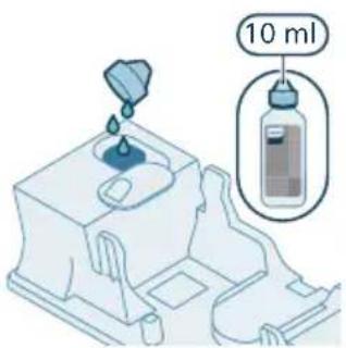
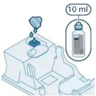
4 (Optional) If you wish to add a liquid floor cleaner into the aqua tank, opt for a low-foaming or non-foaming variety that can be diluted. We recommend the XV1792 Philips Floor Cleaner. Add only a few drops of the liquid cleaner to the water.
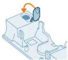
Isometric illustration of a mechanical component with a circular component and an arrow indicating rotation, with no text or symbols.

5 Close the aqua tank properly.

Mechanical assembly diagram showing a robotic arm interacting with a base component, with no text or symbols visible.

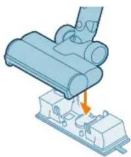
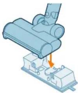
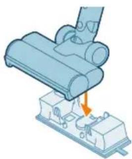
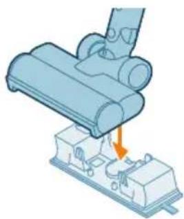
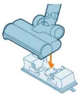
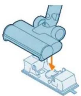
6 Attach the prepared aqua tank to the aqua nozzle and you're set to begin. For proper usage, it is essential to firmly attach the tank to the wheels of the nozzle when it's at the correct orientation.

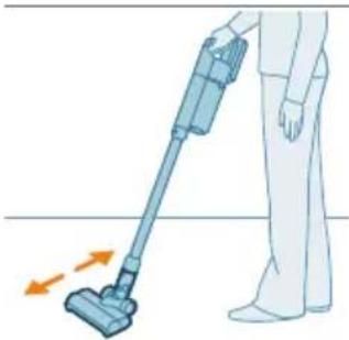
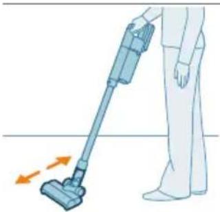
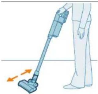
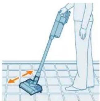
Illustration of a person using a vacuum cleaner on tiled floor, with motion arrows indicating movement, with no text or symbols.

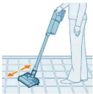
7 Press the on/off button to switch on the appliance. You can effectively clean hard floors with the attached aqua module on the nozzle.
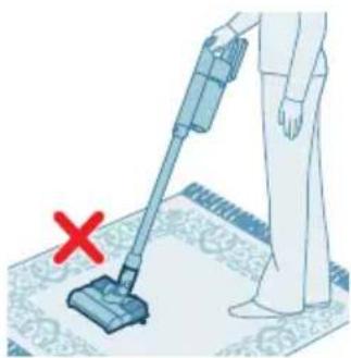
Illustration of a person using a vacuum cleaner on a patterned rug, with a red X mark indicating no text or symbols.

Note: The aqua module is not suitable for soft floors like carpet.
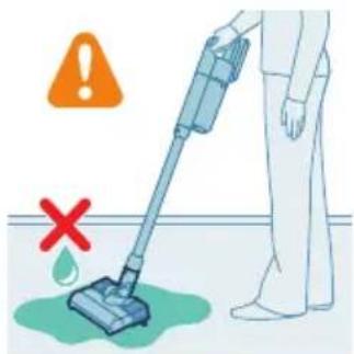
Safety warning illustration showing a person using a vacuum cleaner with a red 'X' indicating failure or damage, and an orange warning symbol.

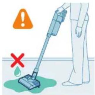
Caution: The aqua module should not be used to pick up water puddles.

Tips and other important information

  • It is not necessary to vacuum the floor before mopping, as the Vacuum & Mop set-up actively wet-cleans your hard floor to capture all kinds of dirt, including liquids and stains. On carpets and rugs, use the Vacuum only set-up.
  • The appliance can leave a small puddle of water on the floor if you do not move the appliance while switching it off. You can reduce the size of the puddle by moving the appliance while switching it off. If needed, you can remove the last drops with a cloth.

Usage restrictions

  • The Vacuum & Mop set-up is suitable for vacuuming and mopping all types of hard floors, except uncoated wooden floors.
  • The Vacuum & Mop set-up is intended for regular cleaning of hard floors. Always follow the cleaning instructions for your hard floor when you use this appliance.
  • If you want to add a liquid floor cleaner other than XV1792 Philips Floor Cleaner to the water in the clean aqua tank, make sure that you use a low-foaming or non-foaming liquid floor cleaner that can be diluted in water like XV1792 Philips Floor Cleaner.
  • As the clean aqua tank has a capacity of 300 ml, you only have to add a few drops (max 10ml) of liquid floor cleaner to the water.
  • If you use the Vacuum & Mop set-up on linoleum floors, only do so on linoleum floors that are properly affixed to prevent linoleum from being drawn into the nozzle.
  • If you move/lift the appliance over a carpet or rug when it is switched off, wastewater droplets may end up on your carpet or rug.
  • Do not push the appliance over the floor grilles of convector heaters. As the appliance cannot pick up water that comes out of the nozzle when you move it over the grille, water ends up at the bottom of the convector pit.

- While cleaning, do not lift the nozzle from the floor or move the nozzle sideways, and do not make strong turns, as this leaves water traces. Only move forwards and backwards.

i Note: The operating time depends on the power level used during cleaning.

Versatile usage and accessories
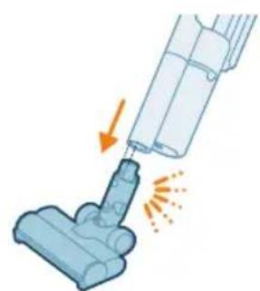
Illustration of a vacuum cleaner emitting exhaust flames, with no text or symbols present.

Warning: When using any accessory, do not vacuum up water or other liquids.

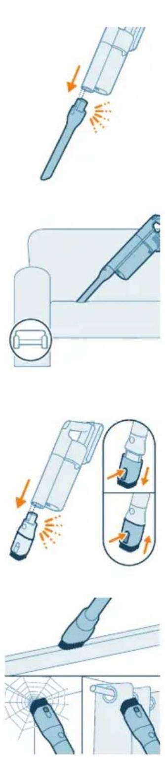
Using the nozzle

1 Attach the nozzle directly to the handheld.

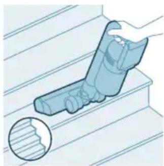
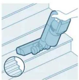
Illustration of a hand holding a tool on stairs, with a magnified inset showing a textured surface (no text or symbols).

2 This combination is for cleaning dynamic surface height, such as stair case.
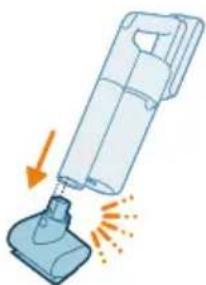
Illustration of a vacuum cleaner emitting exhaust flames (no text or symbols).

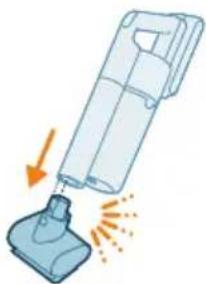
Using the Mini TurboBrush

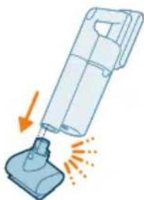
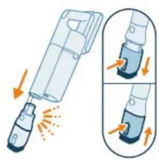
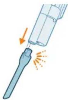
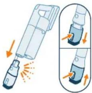
1 To attach the Mini TurboBrush, insert the tube of the handheld into the Mini TurboBrush.
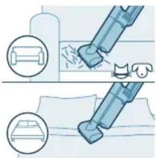
Diagram illustrating a vacuum cleaner's internal structure with labeled components and motion indicators.

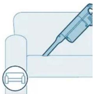
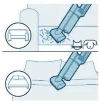
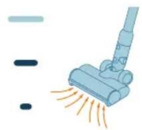
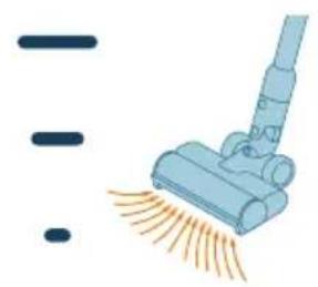
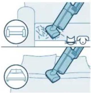
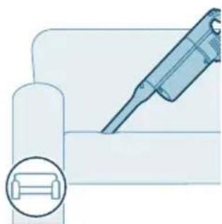
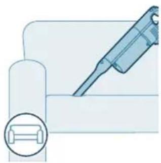
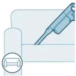
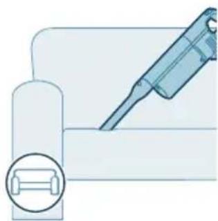
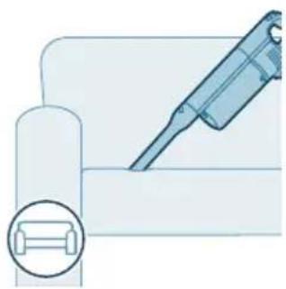
2 You can use the Mini TurboBrush for standard cleaning, for instance of soft areas such as beds and couches. You can adjust the power setting to suit your cleaning needs. 3 You can use the Mini TurboBrush for extra thorough cleaning, for instance to vacuum up pet hair, or to clean small patches of dirt, such as spilled breadcrumbs. You can adjust the power setting to suit your cleaning needs.
PHILIPS 5000 series XC5141 - Using the Mini TurboBrush - 2

Using the crevice tool

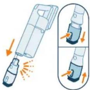
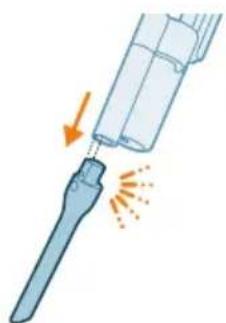
1 To attach the crevice tool, insert the tube or handheld into the crevice tool.

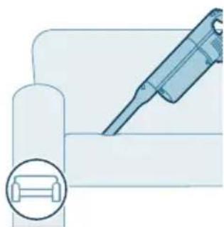
2 You can use the long crevice tool to clean narrow corners or hard-to-reach places. You can adjust the power setting to suit your cleaning needs.

Using the combination tool

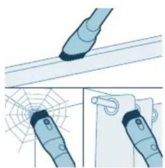
1 To attach the combination tool, insert the tube or handheld into the combination tool.

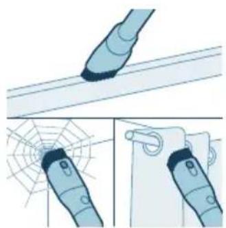
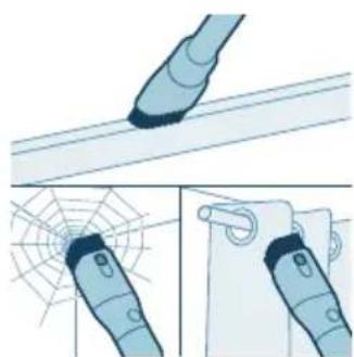
2 The combination tool is designed for cleaning window frames, curtains, or spider webs, with a customizable brush release and illumination settings.

After use – Maintenance

Frequent maintenance after each cleaning cycle

Dust bucket maintenance

Empty the dust bucket after each use or when the dust is reaching the MAX level indicator.
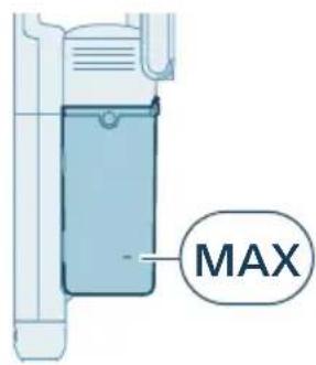
MAX

OFF ①

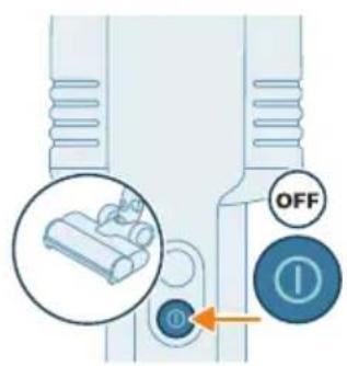
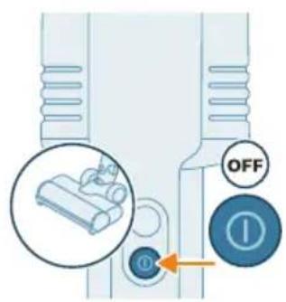
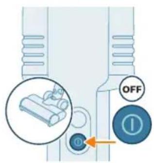
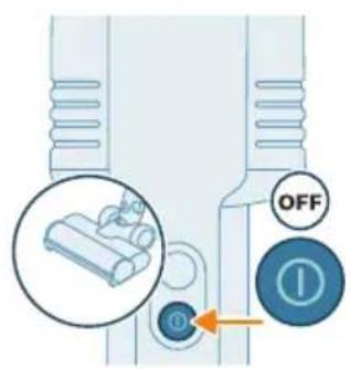
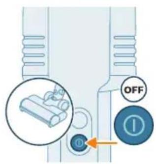
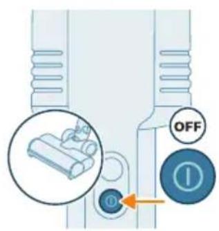
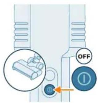
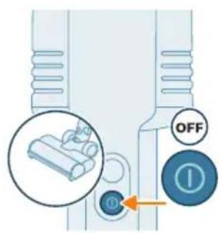
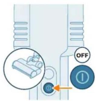
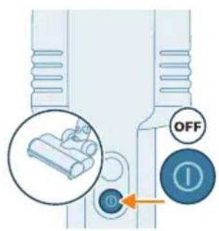
1 Switch off the appliance.

Diagram showing a device with labeled parts and directional arrows, likely illustrating a mechanical or electrical component.

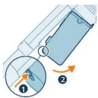
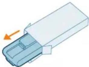
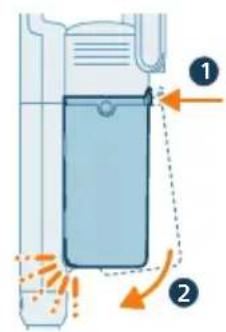
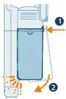
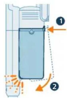
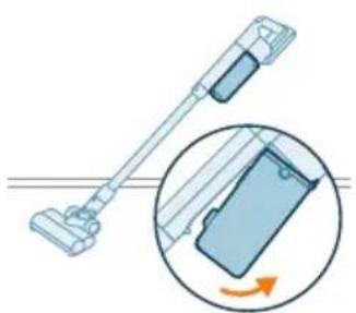
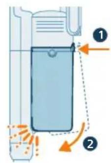
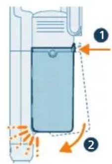
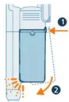
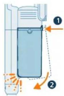
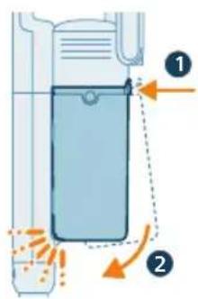
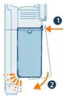
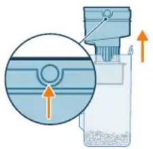
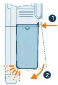
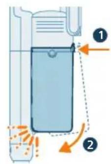
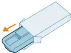
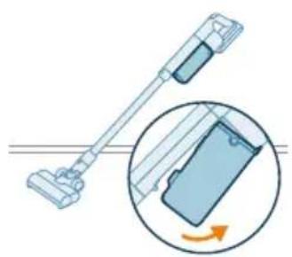
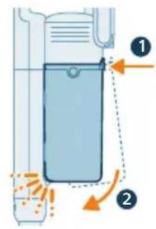
2 Hold the appliance at a 45-degree angle as shown in the illustration. Remove the dust bucket by pressing the release button, located at the bottom of the bucket.
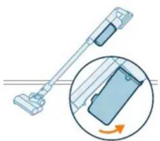
Diagram of a vacuum cleaner with an inset showing the mechanism of rotation (no text or symbols present).

Note: Remove the dust bucket while keeping the appliance in an upright position to avoid spilling of debris.
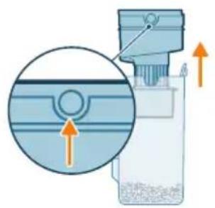
Diagram of a mechanical device with an inset showing a cross-section of a component (no text or symbols present).

3 Hold onto the two indented circles on the side of the cyclone. Remove the cyclone from the dust bucket by lifting it out from the bucket.
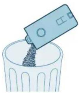
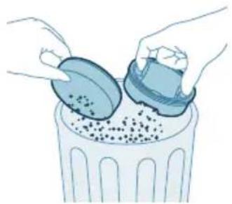
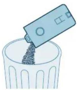
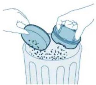
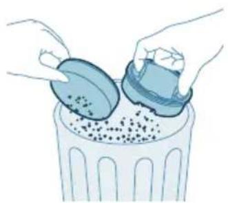
Illustration of a plastic bag pouring granular material into a trash bin (no text or symbols).

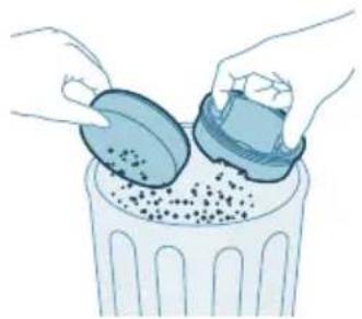
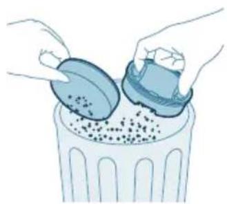
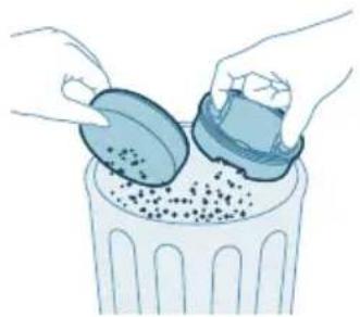
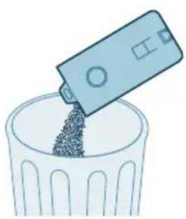
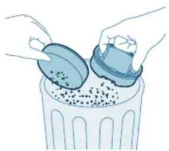
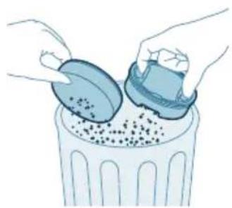
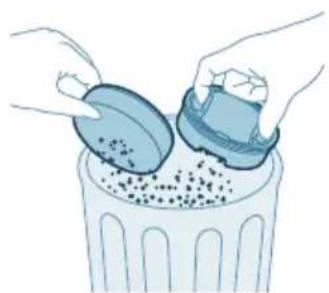
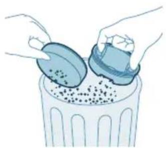
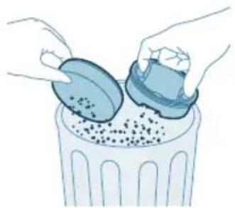
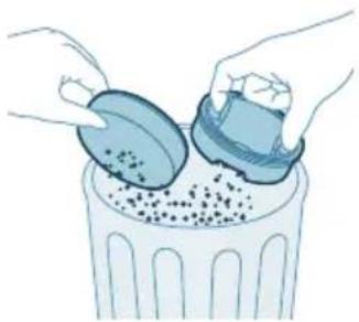
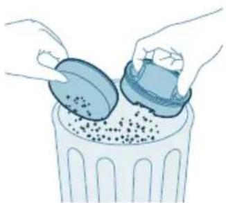
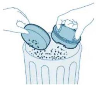
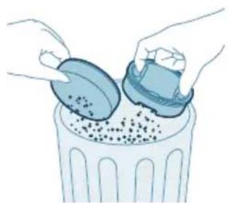
4 Empty the collected dust in the dust bucket over the trash bin.
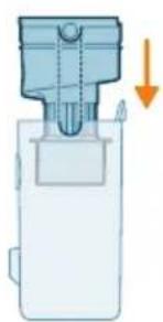
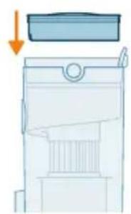
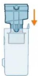
Diagram of a mechanical device with an arrow indicating downward motion (no text or symbols present).

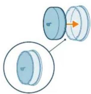
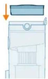
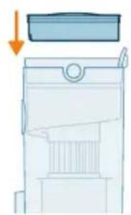
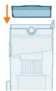
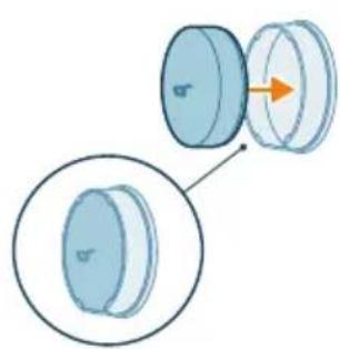
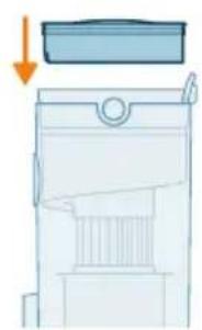
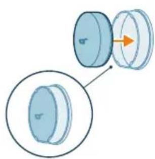
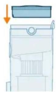
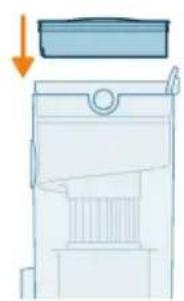
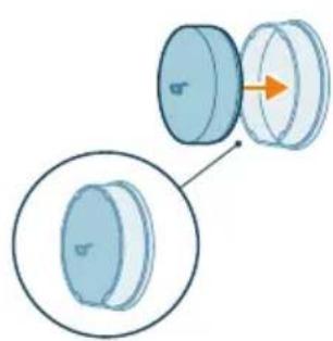
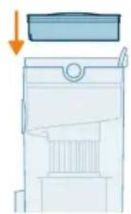
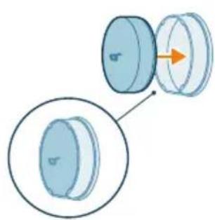
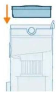
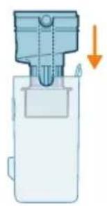
5 Place the cyclone back in the dust bucket. Make sure the two parts are aligned: the two semicircles must be connected to each other.
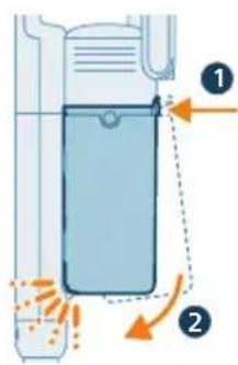
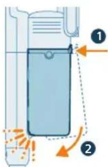
Diagram of a chemical reactor with labeled components and flow indicators.

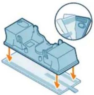
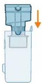
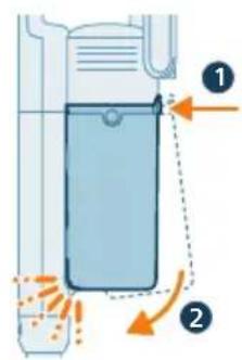
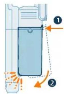
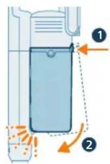
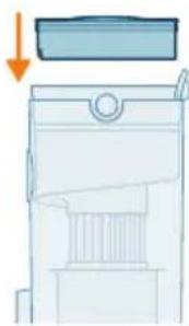
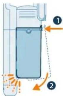
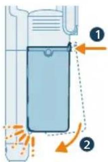
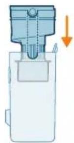
6 Place back the assembled bucket. First align the filter side of the bucket before hinging it in place.
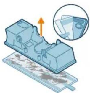
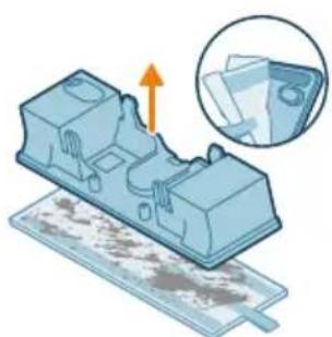
Illustration of a mechanical component with an arrow indicating upward motion, alongside a magnified inset showing a close-up of a sheet of paper (no text or symbols present).

Aqua tank maintenance

Clean the aqua tank after each use.

1 Remove the microfiber mopping pad.
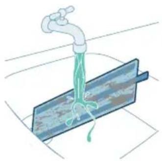
Illustration of a faucet pouring liquid into a blue container with a green pipe, no text or symbols present.

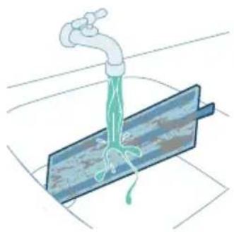
2 Rinse the mopping pad under the tap and wash it by hand or in a washing machine.
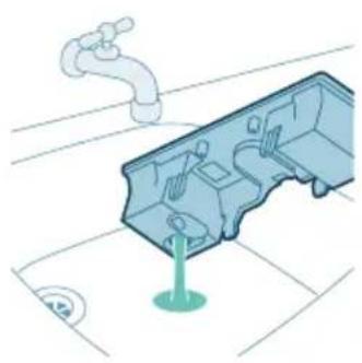
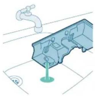
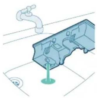
Illustration of a faucet and a plastic housing component with a green base, no text or symbols present.

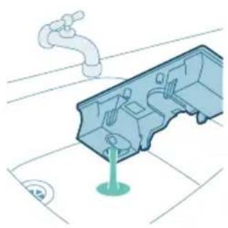
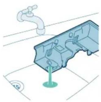
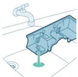
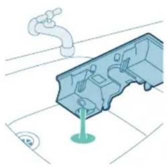
3 Pour out any remaining water in the aqua tank.
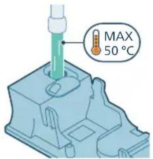
MAX 50 °C

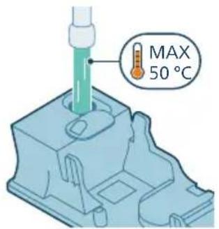
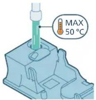
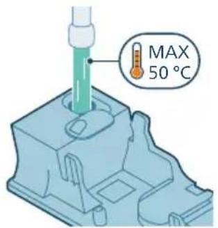
4 Fill the aqua tank with water.

Diagram illustrating fluid flow around a device with labeled components and motion arrows.

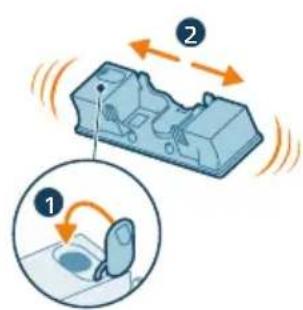
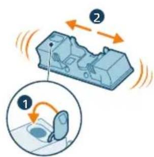
5 Close the aqua tank properly and shake the aqua tank to remove detergent residuals.
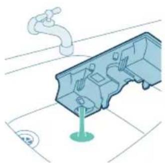
Isometric illustration of a mechanical component with a faucet and a green base, no text or symbols present.

6 Empty the aqua tank and leave it open to dry.
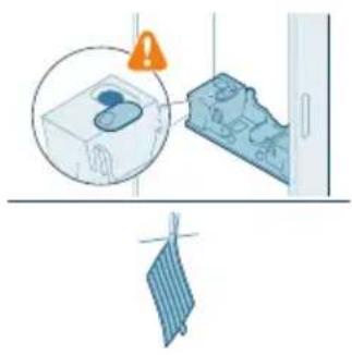
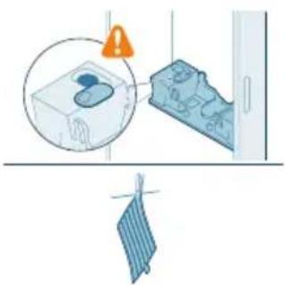
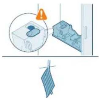
Illustration of a washing machine with a warning sign and clothes hanging, no text or symbols.

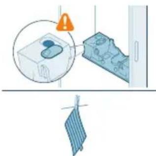
7 Make sure to not lose the tank cap during storage. Hang the microfiber mopping pad dry.

Note: We recommend replacing the microfiber mopping pad every 6 months (accessory XV1630).

Periodic maintenance intermittently

Dust management system maintenance

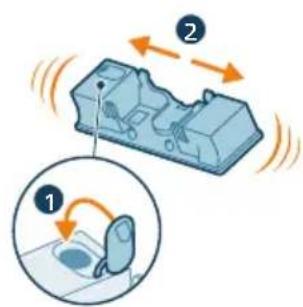
For optimal performance, we recommend cleaning the filter of your vacuum cleaner monthly and replacing the filter every six months (accessory XV1651).

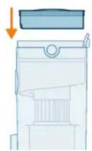
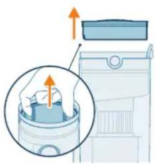
1. Lift the filter to remove it from the dust bucket.
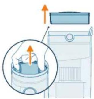
Illustration of a hand inserting a component into a device, showing airflow direction, no text or symbols.

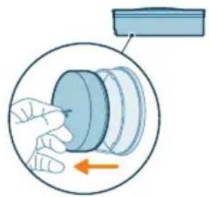
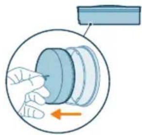
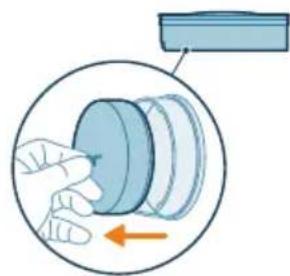
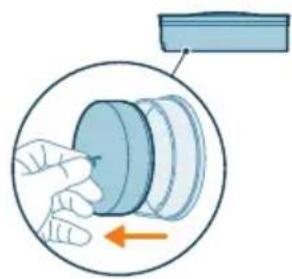
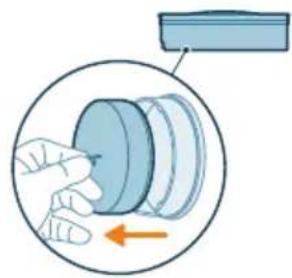
2. Remove the washable foam filter from the plastic filter casing.
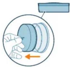
Illustration of a hand pressing down on a cylindrical component with an arrow indicating rotation, no text or symbols.

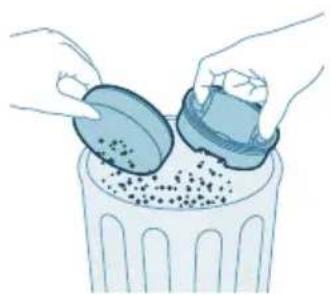
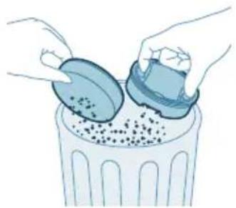
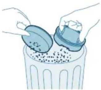
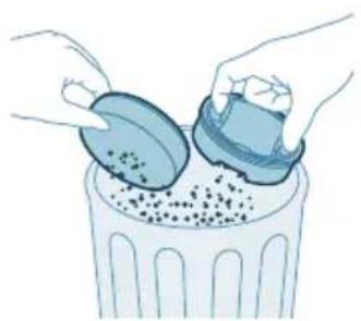
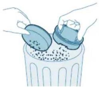
Illustration of hands sorting and dumping material into a trash bin, no text or symbols.

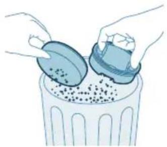
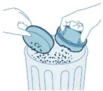
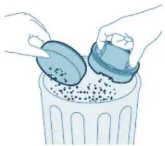
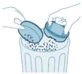
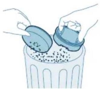
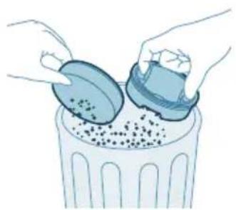
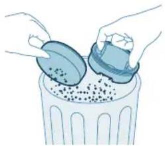
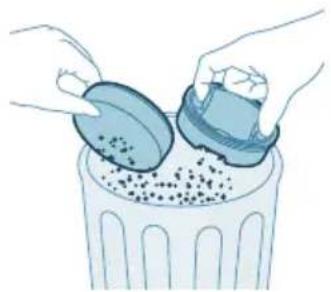
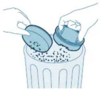
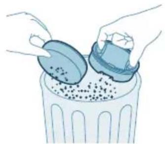
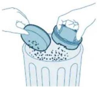
3. Tap both the filter casing and the foam filter over a trash bin.

Note: Make sure to clean the filter case thoroughly by tapping it firmly over a trash bin until no more dust is released from the filter case.
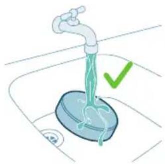
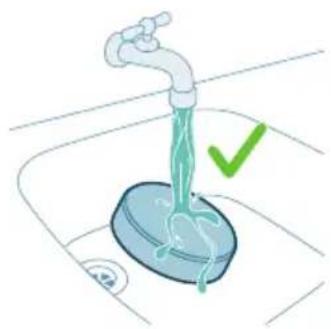
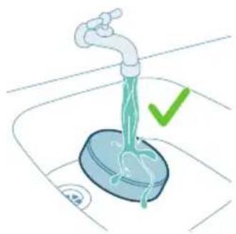
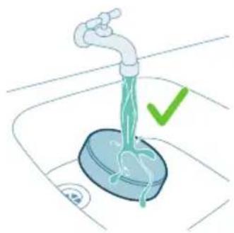
Illustration of a faucet pouring liquid into a container with a green checkmark indicating water level, no text or symbols.

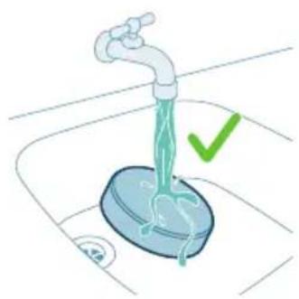
4. Rinse the foam filter under the tap.

Illustration of a hand holding a blue object with green droplets, no text or symbols present.

5. Squeeze the foam filter till clean water comes out.

Note: For best cleaning result, run the water through the filter with the dirtier side facing downwards, allowing deeply set dust to be washed out.

Note: Do not rinse the filter case.
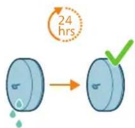
24 hrs

6. Leave the washed filter to dry for 24 hours before reassembling the foam filter in the filter casing.

Note: Do not dry the sponge filter in direct sunlight, on the radiator, or in the tumble dryer.
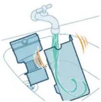
Illustration of a faucet spraying water into a device with motion lines indicating flow, no text or symbols.

7. For thorough maintenance, clean the dust bucket and cyclone under a running tap or in warm soapy water.
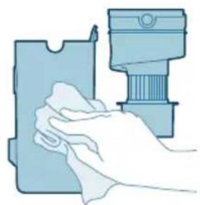
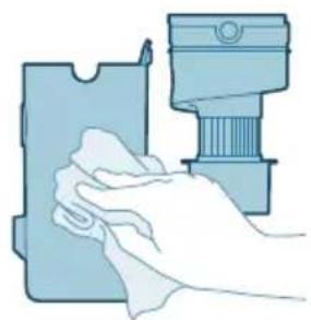
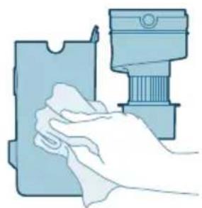
Illustration of a hand cleaning a blue plastic sheet with a mechanical component nearby, no text or symbols.

8 Wipe the cleaned dust bucket and cyclone dry.

Caution: Make sure all parts are completely dry before you reassemble them.
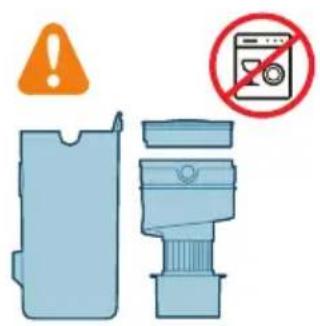
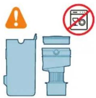
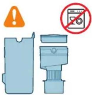
Safety warning and prohibition symbol for a washing machine, featuring an orange warning sign and a blue device with a 'no' symbol.

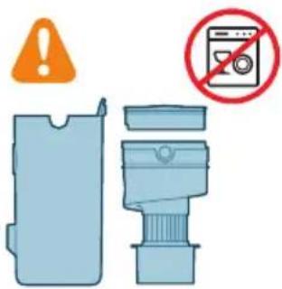
Note: All parts cannot be cleaned in the dishwasher.

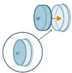
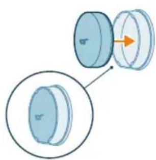
Diagram showing a cylindrical object with an arrow pointing to its cross-section, and a magnified inset of its side view, no text or symbols.

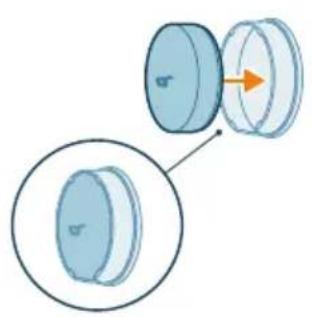
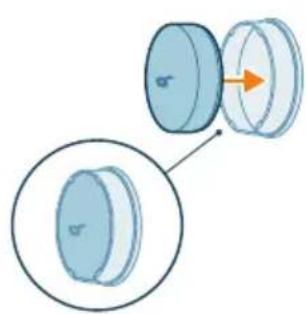
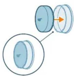
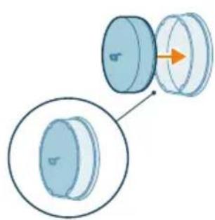
9 Insert the form filter into the filter casing.
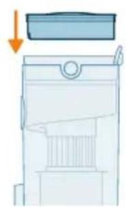
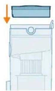
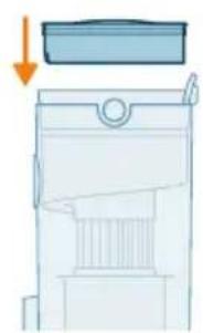
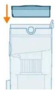
Diagram of a mechanical device with a downward arrow indicating force or direction, no text or symbols present.

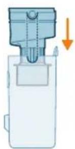
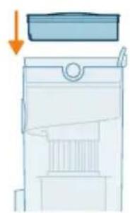
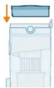
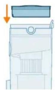
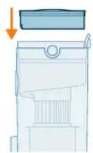
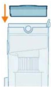
10 Reassemble the filter in the dust bucket.
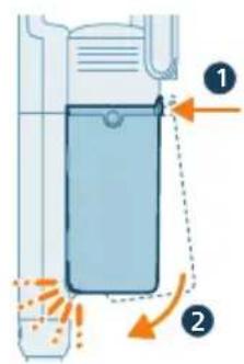
Diagram of a chemical reactor with labeled components and directional arrows indicating flow or movement.

11 Place back the assembled bucket. First align the filter side of the bucket before hinging it in place.

Note: After maintenance, always make sure the filter is assembled in the appliance before using it.
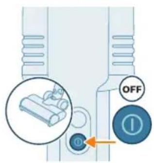
OFF ①

Nozzle maintenance

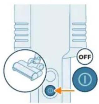
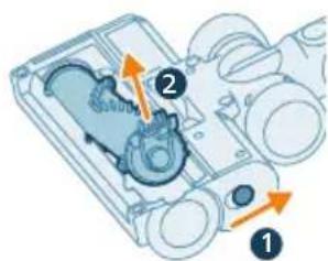
1 Always switch off the appliance before cleaning the nozzle brush.
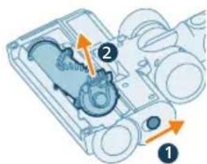
Technical diagram of a mechanical device with numbered components and directional arrows indicating motion or flow.

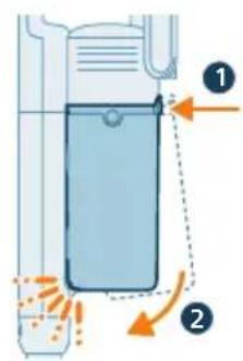
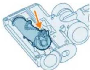
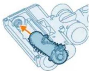
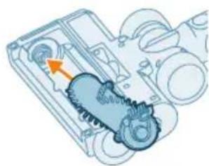
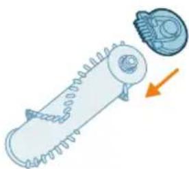
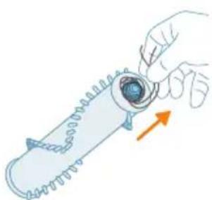
2 Hold the button on the side of the nozzle with one hand while removing the brush with the other hand.
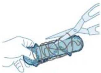
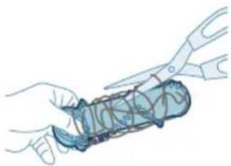
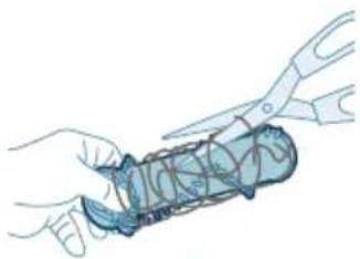
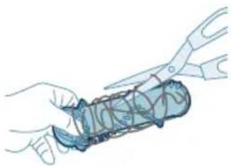
Illustration of hands using scissors to cut a blue object with coiled lines (no text or symbols)

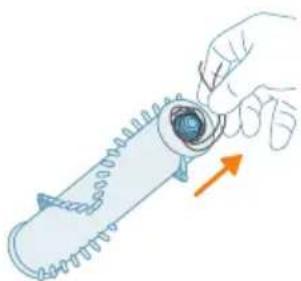
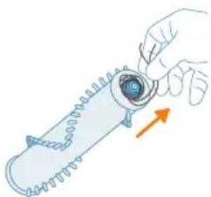
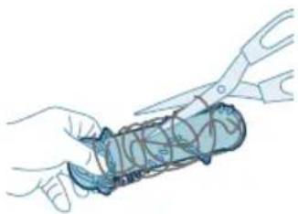
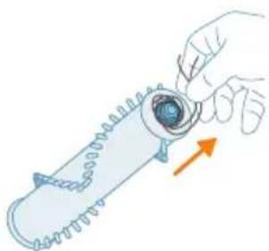
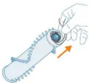
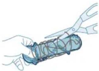
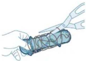
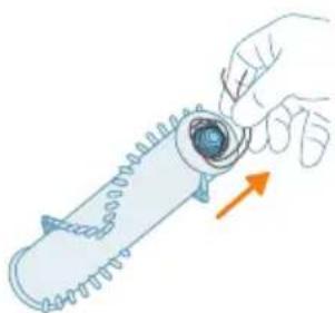
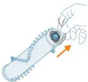
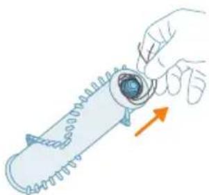
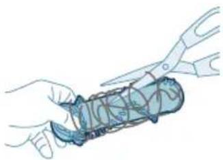
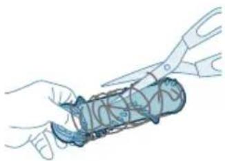
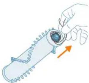
3 Carefully detach any tangled hair from the brush. Support the removal of pollution with a pair of scissors.
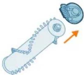
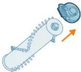
Diagram of a mechanical component with spring and housing, showing an upward force arrow (no text or symbols)

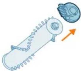
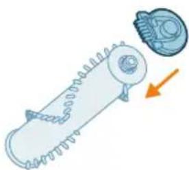
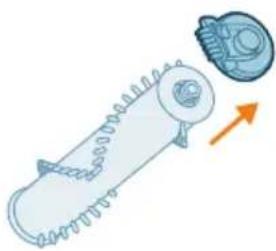
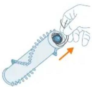
4 Remove the side cap.

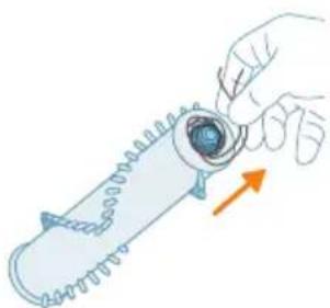
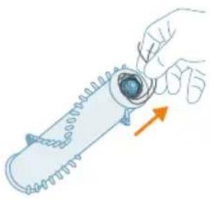
Illustration of a hand holding a cylindrical object with an arrow indicating direction (no text or symbols)

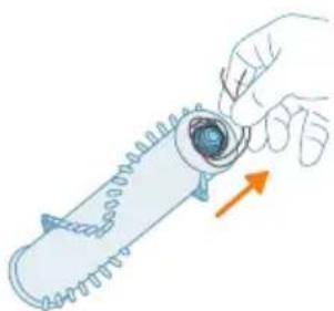
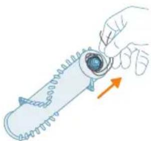
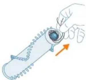
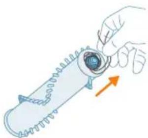
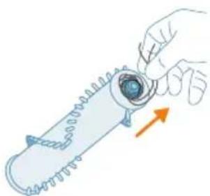
5 Detach any tangled hair in the brush.
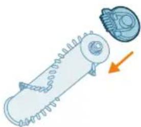
Diagram of a mechanical component with a gear and housing, showing internal structure and motion direction (no text or symbols)

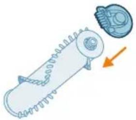
6 Reassemble the cap.

Mechanical assembly diagram showing a gear and motor components with an orange arrow indicating motion direction (no text or labels)

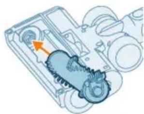
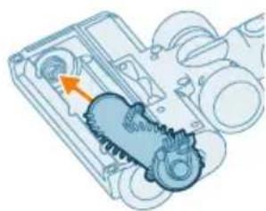
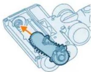
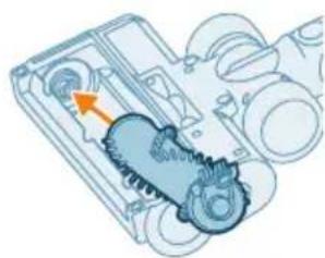
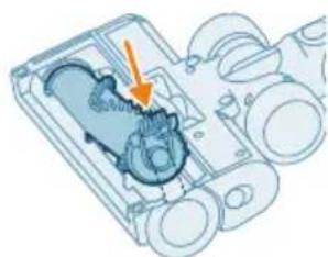
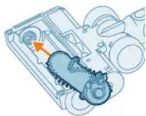
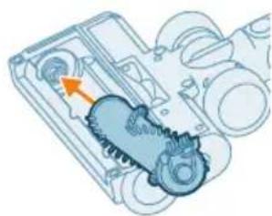
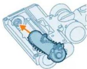
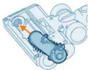
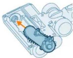
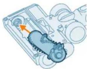
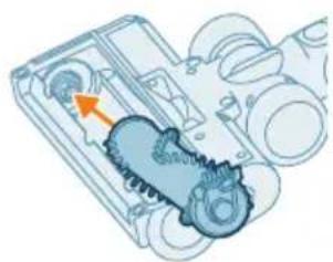
7 When reassembling the brush, ensure proper alignment by first placing one side in position before clicking in the other side.
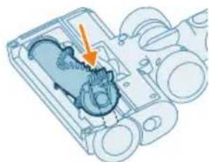
Mechanical assembly diagram showing gear and housing components with an arrow indicating motion (no text or labels)

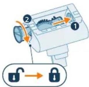
8 Lock the nozzle brush by securing it until you hear a "CLICK" sound.

Note: Check and remove any pollution around the nozzle wheels.
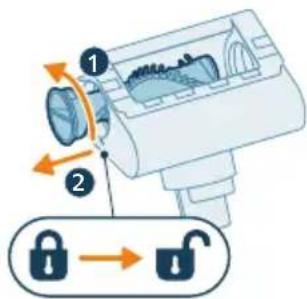
Diagram illustrating lock mechanism with labeled components and lock symbol

Mini TurboBrush maintenance (XC5141 and XC5142 only)

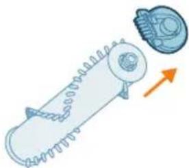
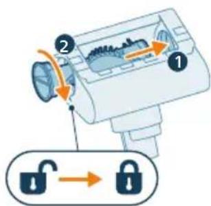
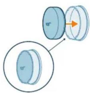
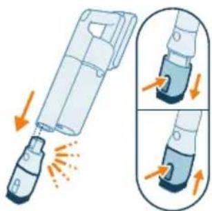
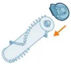
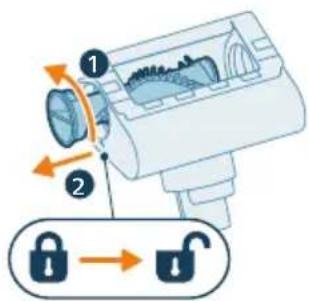
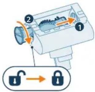
1 Rotate the side lock counter-clockwise to release the brush from its position.
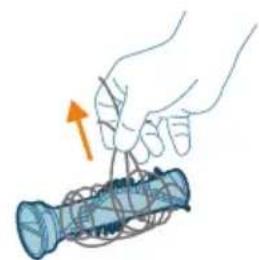
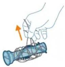
Illustration of a hand holding a blue cylindrical object with a yellow arrow indicating upward motion (no text or symbols)

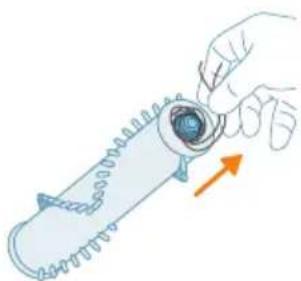
2 Use your hands or a pair of scissors to remove any pollution from the brush.
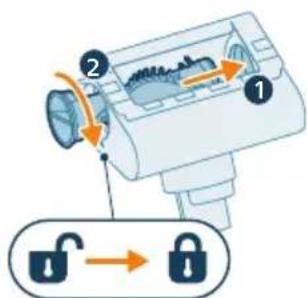
Diagram illustrating a lock mechanism with labeled components and lock states

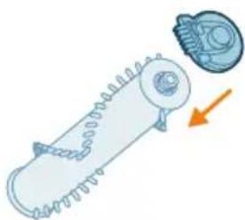
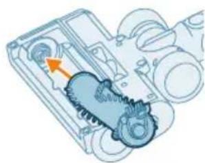
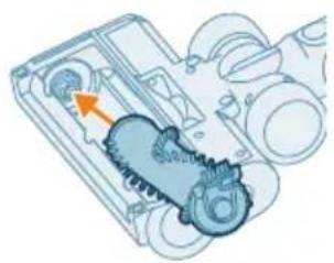
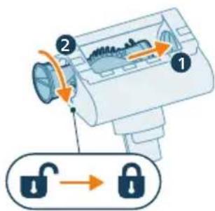
3 When reassembling the brush, simply align the brush back in its original position. Make sure the inner end is aligned. Rotate clockwise to lock the brush. When the brush is properly assembled, you will hear a "CLICK" sound.

Aqua tank maintenance

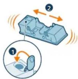
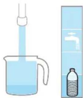
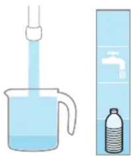
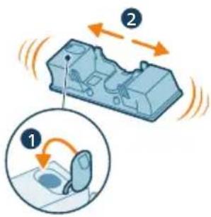
Descale the aqua tank once every month to avoid limescale build-up.
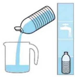
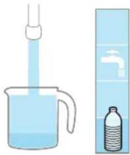
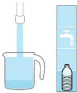
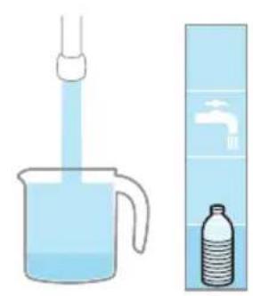
Illustration of a plastic bottle pouring liquid into a beaker with a water tap, next to a bottled water bottle (no text or symbols)

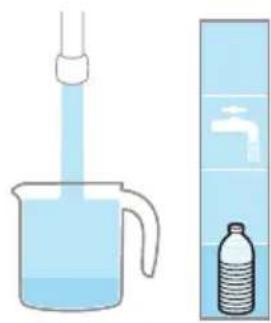
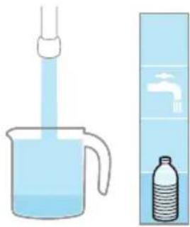
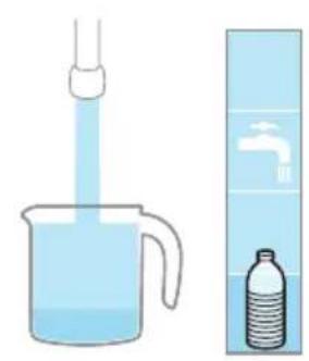
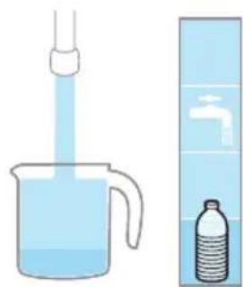
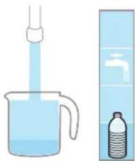
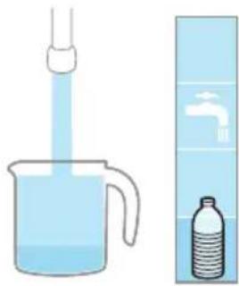
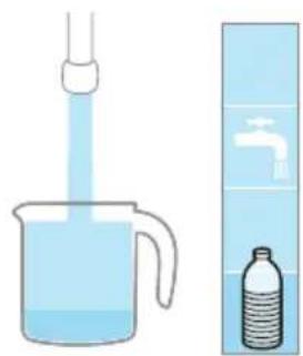
1 Add some descaling liquid to a measuring cup.
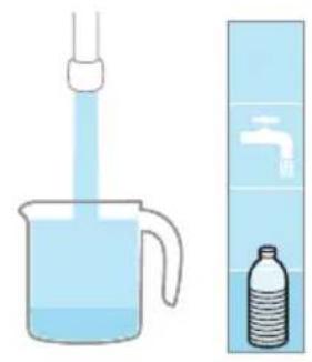
Illustration of a beaker with liquid being inverted and a water bottle beside it (no text or symbols)

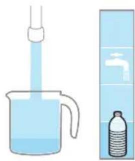
2 Add the correct amount of water in the measuring cup.
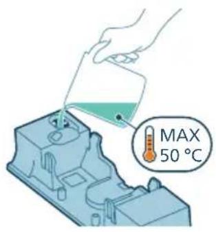
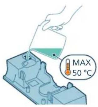
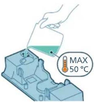
MAX 50 °C

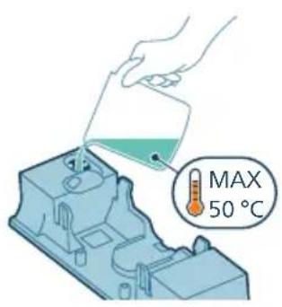
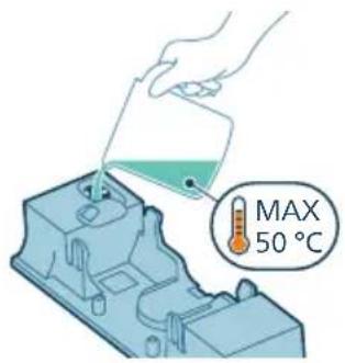
3 Add the mixed liquid in the aqua tank.
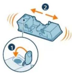
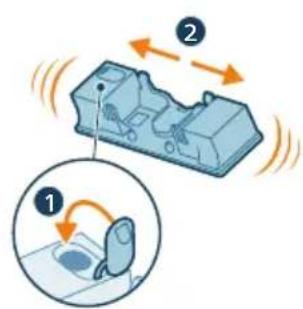
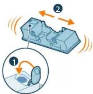
Diagram illustrating fluid flow around a mechanical component with labeled parts and motion arrows.

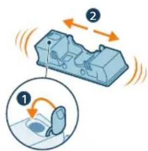
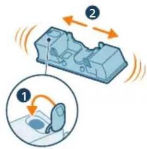
4 Close the Aqua tank properly before shaking the tank for the descaling liquid to spread evenly.
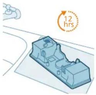
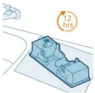
3D illustration of a mechanical component with a circular annotation indicating 12 hours (no text or symbols on the object itself).

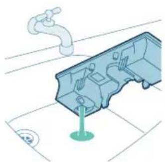
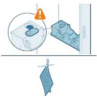
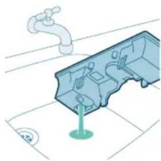
5 Leave the aqua tank (without the microfiber mopping pad) upright over 12 hours. Water is expected to slowly come out from the bottom of the aqua tank. We recommend to place the aqua tank inside the sink or over a cloth.
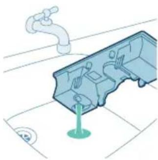
Illustration of a mechanical component with a faucet and a green base, no text or symbols present.

6 Rinse and remove any remaining liquid inside the aqua tank.
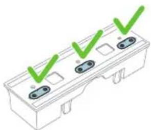
Illustration of a three-pin electrical connector with green checkmarks indicating status (no text or symbols).

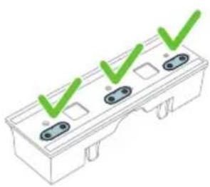
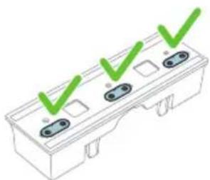
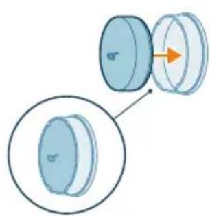
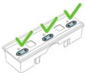
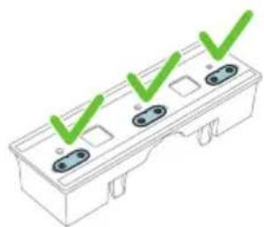
Note: Always make sure the three water strips are in place. The water tank only functions properly when all three water strips are in place.

Replacement

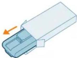
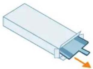
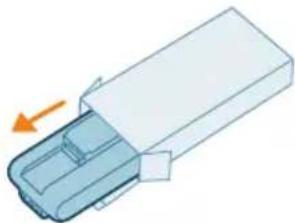
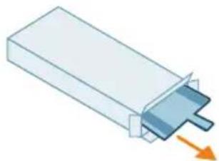
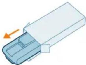
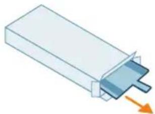
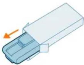
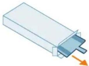
To buy accessories or spare parts, visit www.philips.com/parts-and-accessories or go to your Philips dealer. You can also contact the Philips Consumer Care Center in your country.

Replacement parts and type numbers:

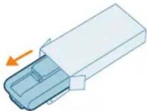
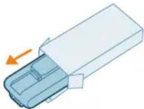
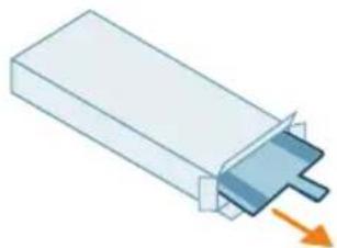
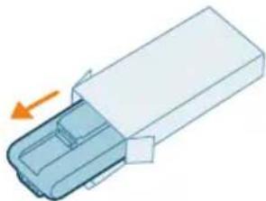
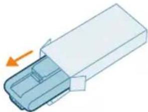
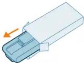
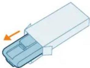
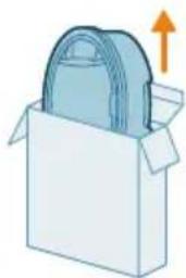
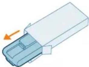
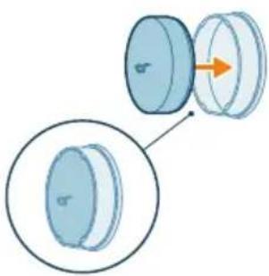
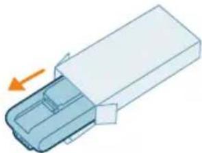
Replacement filter XV1651/01
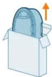
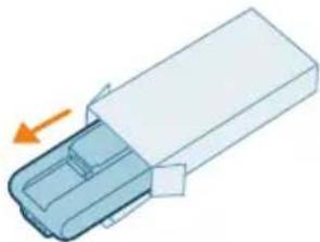
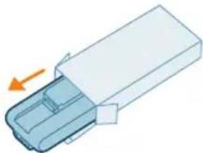
Illustration of a box with a bag inside, showing an upward arrow (no text or symbols).

XV1651/01

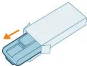
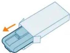
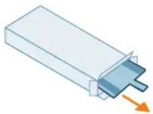
Battery XV1653/01

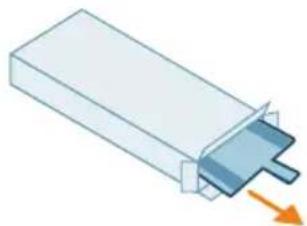
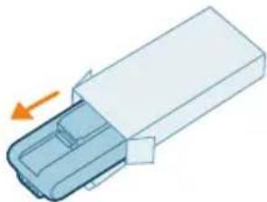
3D diagram of a plastic container with an arrow indicating direction (no text or symbols).

XV1653/01

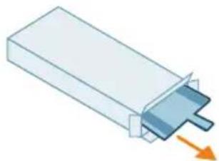
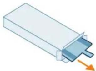
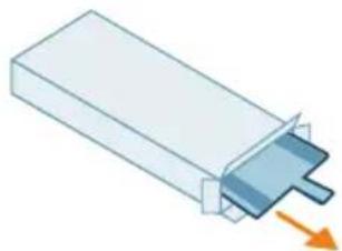
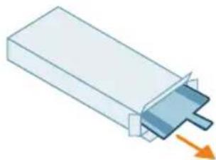
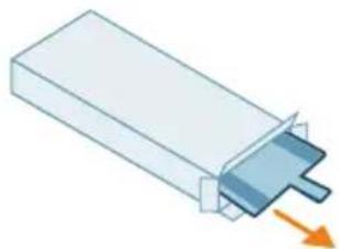
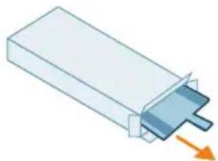
Microfiber mopping pad XV1630/01
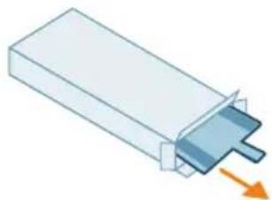
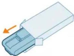
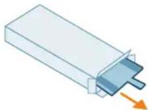
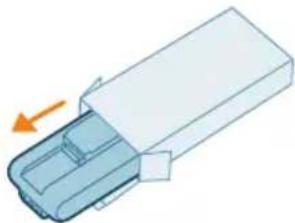
3D illustration of a rectangular electronic component with a blue internal structure and an orange arrow indicating direction (no text or symbols).

XV1630/01

Note: Replace the filter and the microfiber mopping pad every 6 months to ensure maximum performance.

User interface signals and their meaning

Signal Meaning of signal

E2 The appliance is operated above or below the functioning

62

temperature. Please use and store the appliance in a room with a temperature between 0 °C and 35 °C. Charge the appliance or battery at a temperature between 10 °C and 35 °C.

E5 The battery does not have enough power to be switched on.

88

Connect the appliance again to the charger. If the appliance still does not charge, take it to a Philips service center or contact the Consumer Care Center.

Signal Meaning of signal

E9 There is a short circuit in the nozzle.

88

Take it to a Philips service center or contact the Consumer Care Center.

i4 The brush is stuck or objects are stuck in the air flow channel.

8

Make sure the appliance is switched off. Clean the nozzle according to the user manual and check the tube by removing the tube from the main appliance. Remove the object in the nozzle or tube and restart the appliance.

When used on certain carpets, the brush may become stuck. If this happens, adjust the floor cleaning direction and power mode to continue cleaning.

i5 The motor is jammed or damaged.

8

Remove the battery, wait 10 seconds, and then put the battery back. If this does not work, please take the appliance to a Philips service center or contact the Consumer Care Center.

i6 The display shows i6 (seen from upside down with the battery icon

b %

under i6). The adapter is not removed.

Remove the adapter before operating the appliance.

Signal Meaning of signal

i7 The display shows i7 seen from upside down with the battery icon

Abstract pattern of black dots and gray squares on white background, no text or symbols present.

under i7). A wrong adapter is used.

Make sure that you use the adapter supplied.

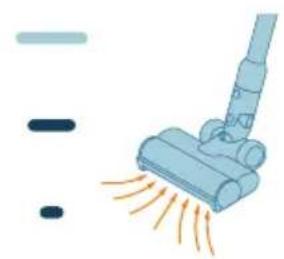
% 0 0 1 2 3 4 5 6 7 8 9 10 11 12 13 14 15 16 17 18 19 20 21 22 23 24 25 26 27 28 29 30 31 32 33 34 35 36 37 38 39 40 41 42 43 44 45 46 47 48 49 50

The battery level is low and needs to be charged. Charge the appliance or the battery via the suggested charging methods.

Troubleshooting

This chapter summarizes the most common problems you could encounter with the appliance. If you are unable to solve the problem with the information below, visit www.philips.com/support for a list of frequently asked questions or contact the Consumer Care Center in your country.

Dry cleaning

Problem Possible cause Solution

The appliance does not respond when the on/off button is pushed.The display shows the battery empty icon.To charge the battery, connect the appliance to the charging station or attach the handheld (with the battery installed) directly to the power plug of the adapter.
The charging station is not stable on the wall.The screws holding the charging station are loose.Tighten the screws.
The screws are not the right size.Mount the charging station with the supplied screws.
The charging station is not attached to a stable wall.Check that the wall on which the charging station will be mounted is stable.
The appliance suddenly stops working.When the appliance has an internal malfunction, the buttons will not respond and the screen will remain blank.Connect the appliance to the charging station or attach the handheld vacuum cleaner directly to the adapter. Check the display. If an error code appears, you can find its meaning in the previous chapter about user interface signals.

Problem Possible cause Solution

(code: E2) The appliance is not working at a suitable temperature.Use and store the appliance at a temperature between 0 °C and 35 °C. Charge the appliance or battery at a temperature between 10 °C and 35 °C.
(code: i4, i5) The brush is stuck or objects are stuck in the air flow channel.Make sure the appliance is switched off. Clean the nozzle according to the instructions and check the tube by removing the tube from the main appliance. Remove the object in the nozzle or tube and restart the appliance.
(code: E9) The motorized nozzle is short circuited.Take it to a Philips service center or contact the Consumer Care Center.
The appliance has a lower suction power than usual.The filter and the cyclone are dirty.Empty the dust bucket. Clean the filter and the cyclone according to the instructions. Make sure the filter is washed at least once a month, when using the appliance regularly. Make sure hair and dirt stuck in the cyclone are removed.
The dust bucket is not attached properly to the appliance.Make sure the dust bucket is attached properly.
The filter has expired and needs to be replaced.If it is no longer possible to clean the filter according to the instructions, you can buy new filters in the online Philips shop at www.philips.com/support or at your Philips dealer.
Dust escapes from the appliance.The filter is dirty. Clean the filter according to the instructions.
The filter is not present in the appliance.Make sure that the filter is in the appliance and assembled correctly.
Something is blocking the cyclone.Check the cyclone for stuck objects and remove any object blocking the cyclone. Also ensure all hair and dirt stuck in the cyclone are removed.
The dust bucket is not properly attached to the appliance.Empty the dust bucket and attach it correctly to the appliance.
The appliance is rotated or flipped when the power is off.Keep the appliance upright when the power is off.
The appliance does not move smoothly across the floor when cleaning a carpet.The selected suction power has been too high.Try all three power settings and locate the one that works best for your maneuverability needs.
The vacuuming direction is not aligned with the direction of the carpet piles.Check the direction of the carpet piles and adjust the vacuuming direction to align with the direction of the piles.

Problem Possible cause Solution

The brush does not turn anymore.The brush is clogged with hair or dirt.Clean the brush by hand or with a pair of scissors.
(code i4) The brush may stop turning when it encounters too much resistance from a high-pile carpet.Adjust the carpet cleaning directions and power modes to continue cleaning.
The roller brush has not been assembled properly into the nozzle after cleaning.Follow the instructions in the cleaning chapter of the user manual to slide the roller brush into the nozzle properly. Confirm your assembly with the "click" sound.
(code: E9) The motorized nozzle is short circuited .Take it to a Philips service center or contact the Consumer Care Center.
The LEDs in the nozzle do not come on.The nozzle has not been attached to the tube or appliance properly.Attach the nozzle to the appliance or handheld properly.
The appliance is not charging.The power plug is not connected properly to the appliance or the adapter is not inserted into the wall socket properly.Make sure that the power plug is connected properly to the appliance and that the adapter is inserted into the wall socket properly.
The power plug is not placed properly in the charging station.Make sure the plug is fixed properly in the charging station. Check if the plug is angled and the charging station is holding the plug in place.
(code i7) An adapter other than the supplied adapter is being used.Make sure that you use the adapter supplied.
(code E5) The battery malfunctions.The battery has failed. Replace the battery.
If you have checked the above and the appliance still does not charge, take it to a Philips service center or contact the Consumer Care Center.
The appliance is charging very slow.An external adapter or an adapter from other appliances is used.Charge the appliance with the supplied adapter.
The battery is charged and attached, but the appliance cannot be switched on.The appliance is still connected to the adapter.Remove the appliance from the adapter before restarting it.
Something is wrong with the appliance.Take it to a Philips service center or contact the Consumer Care Center.

Problem Possible cause Solution

The Mini TurboBrush does not function properly.The roller brush is blocked. Remove hairs from the brush with a pair of scissors. Follow the instructions in the user manual.
The roller brush is blocked by fabric or surfaces during cleaning.Keep the Mini TurboBrush aligned with the surface and do not push the Mini TurboBrush into soft surfaces.
The roller brush is not properly inserted into the Mini TurboBrush.Make sure that roller brush and the Mini TurboBrush are properly connected and that there is no gap between the parts. Follow the instructions in the manual.
The appliance delivers static shocks.The appliance builds up static electricity. The lower the air humidity, the more state electricity is build up.Discharge the appliance by frequently holding the tube against other metal objects in the room (for example the legs of a table or chair, etc.). Or raise the air humidity level in the room.
The dust and dirt that is vacuumed up is static.Empty the dust bucket and clean the filter according to the instructions in the previous chapter.

When using the Vacuum and Mop Nozzle

Problem Possible cause Solution

The water flow from the water tank is reduced.The microfiber mopping pad is not placed correctly and blocks the wetting strip as a result.Make sure that you place the mopping pad correctly. Check the instructions in the previous chapters for proper placement.
The water tank is empty or nearly empty.Refill the water tank.
A microfiber mopping pad is used that is not supplied by Philips.Only use an original Philips microfiber mopping pad. The mopping pads can be bought in the online Philips shop at www.philips.com/support or at your Philips dealer.
Lime scale has build up in the wetting strip.Buy a new wetting strip in the online Philips shop at www.philips.com/support or at your Philips dealer.
Too much water flows out of the water tank at a too high speed.The water tank cap is not attached properly.Check the cap and make sure it is fully and properly closed.
One or more water strips are missing from the bottom of the water tank.Check if all three water strips are present below the tank and placed in the correct orientation. If it is assembled correctly, the three water strips should be flush with the surfaces around it.

Problem Possible cause Solution

The floor dries with stripes. Too much liquid cleaner has been added to the water.Use only a few drops of liquid cleaner or use a cleaner that foams less.
The microfiber mopping pad is not placed correctly.Make sure that the mopping pad is placed correctly. Check the instructions in previous chapters for proper placement.
An incorrect mopping pad is used.Only use Philips XV1630/01 microfiber mopping pad. The mopping pads can be bought in the online Philips shop at www.philips.com/support or at your Philips dealer.

Illustration of a blue vacuum cleaner emitting exhaust flames.

Illustration of a blue vacuum cleaner emitting exhaust smoke.

Illustration of a person using a vacuum cleaner to clean or walk (no text or symbols present)

3D illustration of a mechanical component with arrows indicating assembly or movement, and an inset showing a close-up of a sheet of paper (no text or symbols present)

2 Attach the microfiber mopping pad under the water tank. Align the velcro strips under the water tank and on the back of the cloth.
MAX 50 °C

Illustration of a medical or laboratory procedure showing a pipette inserted into a container with a magnified inset (no text or symbols)

10 Reattach the filter to the dust container.
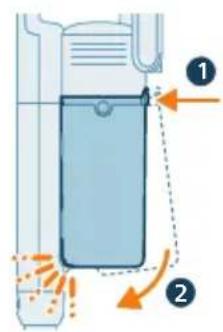
Diagram of a chemical reactor with labeled components and flow indicators

4 Remove the side cover.

Illustration of a hand holding a cylindrical object with an arrow indicating direction.

Illustration of a beaker with liquid being inverted and a water bottle inside a container.

XV1651/01

Battery XV1653/01

3D diagram of a plastic container with an arrow indicating direction.

XV1653/01

Microfiber mopping cloth XV1630/01
3D illustration of a rectangular electronic component with a blue internal structure and an orange arrow indicating direction (no text or symbols)

XV1630/01

E9 Nozzle is short-circuited.

88

3 The appliance is designed to reach a full charge within 4 hours. You can monitor the charging progress on the screen. When the battery is fully charged, the value 100% lights up on the screen. After a few seconds, the display will turn off.
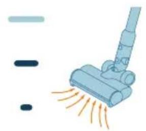
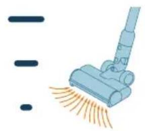
Illustration of a blue vacuum cleaner emitting exhaust flames, with no text or symbols present.

Illustration of a blue vacuum cleaner emitting exhaust smoke, with no text or symbols present.

Illustration of a person using a vacuum cleaner to clean or walk, with no text or symbols present.

Warning: Do not vacuum water or other liquids.
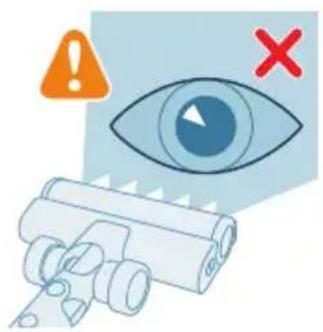
Illustration of an eye with warning symbols, indicating anxiety, with no text present.

3D illustration of a mechanical component with arrows indicating assembly or movement, and a magnified inset showing a close-up of a sheet of paper, with no text or symbols present.

2 Attach the microfiber mopping pad under the water tank. Align the velcro strips under the water tank with those on the back of the cloth.

MAX 50 °C

Illustration of a mechanical tool interacting with a cylindrical component (no text or symbols visible)

i Note: Remove the dust bucket while keeping the appliance upright to avoid spilling dirt.

Diagram of a mechanical device with an inset showing a cross-section of a component (no text or symbols present)

Illustration of hands pouring liquid into a trash bin with granular material (no text or symbols).

4 Rinse the foam filter under the tap.

Illustration of a hand holding a blue object with green droplets, no text or symbols present.

4 Remove the side cover.

Illustration of a hand holding a cylindrical object with an arrow indicating direction.

6. Replace the lid.

Mechanical assembly diagram showing a gear and motor components.

Maintenance of the Mini TurboBrush (XC5141 and XC5142 only)

XV1651/01

Battery XV1653/01

3D diagram of a plastic container with an arrow indicating direction (no text or symbols)

XV1653/01

Microfiber mopping pad XV1630/01

3D illustration of a rectangular electronic component with a blue internal structure and an orange arrow indicating direction (no text or symbols)

XV1630/01

Illustration of a blue vacuum cleaner emitting exhaust flames, with no text or symbols.

Illustration of a blue vacuum cleaner emitting exhaust smoke, with no text or symbols.

Illustration of a person using a vacuum cleaner to clean or walk, with no text or symbols present.

Illustration of a mechanical component with arrows indicating assembly or movement, and an inset showing a close-up of a sheet of paper, with no text or symbols present.

Illustration of hands sorting and dumping material into a trash bin, no text or symbols.

Diagram showing two views of a cylindrical object with an arrow indicating direction, no text or symbols.

Diagram of a mechanical device with a downward arrow indicating force or direction, no text or symbols.

Diagram of a chemical apparatus with labeled parts and directional arrows indicating flow or movement.

OFF ①

6. Replace the lid.

Mechanical assembly diagram showing a gear and motor components with an orange arrow indicating motion direction (no text or labels).

Maintenance of the mini Turbo brush (XC5141 and XC5142 only)

XV1651/01

Battery XV1653/01

3D diagram of a mechanical component with an arrow indicating direction (no text or symbols).

XV1653/01

XV1630/01

1. Turn the wall mount and release the lever. Insert the charging connector. The metal part must be visible and pointing upward on the front of the wall mount.

Diagram illustrating a door lock mechanism with labeled components and directional arrows indicating motion or movement.

2. Close the lever. The lever must click into place.

125 ± 3 cm

3 Securely attach the wall mount to the desired position on the wall. The lowest mounting screw holes must be at a height of approximately 125 cm from the floor.

A Caution: When drilling holes in the wall to attach the wall mount, be careful of the risk of electric shock.

Illustration of a vacuum cleaner with a green checkmark and a magnified inset showing the device (no text or symbols)

The appliance contains a lithium-ion battery. Charging from empty to full takes about 4 hours.

i Note: You can place the handheld appliance on a flat, stable surface and connect the charging cable directly.

Diagram showing a cable with a connector and an inset magnified view of the connector (no text or symbols)

i Note: Another option is to place the battery on a flat, stable surface and connect the charging cable directly to the battery.

graph TD A["Start"] --> B["4 hrs"] B --> C["End"]

3 The appliance is designed to fully charge within 4 hours. You can monitor the charging process on the screen. When the appliance is fully charged, the value 100% will light up on the screen. After a few seconds, the screen will turn off.

Using the appliance

Assembling the appliance

Illustration of a medical device with a magnified view showing internal structure (no text or symbols)

1 Attach the handheld appliance to the tube. You will be sure it is properly installed when you hear a "click" sound.

Illustration of a hand turning a rubber gun into a small mechanical component (no text or symbols)

2 Attach the tube to the nozzle. You will be sure it is properly installed when you hear a "click" sound.

Vacuuming soft and hard floors

Diagram of a device control panel with a blue button labeled '①' and an orange arrow pointing to it (no text or symbols beyond the label)

Illustration of a blue vacuum cleaner emitting exhaust flames (no text or symbols)

Illustration of a blue vacuum cleaner emitting exhaust smoke (no text or symbols)

Illustration of a person using a vacuum cleaner to clean or walk (no text or symbols present)

3D illustration of a mechanical component with arrows indicating assembly or movement, and a magnified inset showing a close-up of a sheet of paper (no text or symbols present)

2 Attach the microfiber mopping pad underneath the water tank. Align the Velcro strips on the water tank with those on the underside of the cloth.

MAX 50 °C

3 Open the rubber stopper on the water tank. Fill the tank with water. Make sure the water temperature does not exceed 50 °C.

10 ml

7 Press the on/off button to turn on the appliance. When the water module is attached to the nozzle, you can effectively clean hard floors.

Illustration of a person using a vacuum cleaner on a patterned rug, with a red X mark indicating no text or symbols.

i Note: The water module is not suitable for soft floors such as carpets.

Illustration showing a person using a vacuum cleaner with warning symbols and a red 'X' indicating a defect or hazard.

Caution: The water module must not be used to collect puddles of water.

2 This combination is suitable for cleaning surfaces of different heights, such as staircases.

Illustration of a vacuum cleaner emitting exhaust plume (no text or symbols)

Using the mini turbo brush

1 To attach the mini turbo brush, insert the tube of the handheld appliance into the mini turbo brush.

Illustration showing a robotic arm crushing a bed, with magnified insets highlighting the components of the device and object.

2 You can use the crevice tool for cleaning corners or hard-to-reach places. You can adjust the power to suit your cleaning needs.

Illustration of a mechanical tool interacting with a cylindrical component (no text or symbols visible)

Using the combination tool

1 To attach the combination tool, insert the tube of the handheld appliance into the combination tool.

Illustration of a handheld device with orange arrows indicating motion or force, showing internal components and movement (no text or symbols)

After use – maintenance

2 Hold the appliance at a 45-degree angle, as shown in the figure. Press the release button located at the bottom of the dust container and remove the container.

Diagram of a handheld vacuum cleaner with an inset showing the device's rotation (no text or symbols present)

Note: Remove the dust container while holding the appliance in an upright position to prevent dirt from spilling.

Diagram of a mechanical device with an inset showing a component being inserted into a container, no text or symbols present.

3 Hold the cyclone by the two recessed circles on the sides. Pull the cyclone out of the dust container.

Illustration of a plastic bag pouring granular material into a trash bin (no text or symbols)

4 Empty the collected dust from the dust container into a trash bin.

Diagram of a mechanical device with an arrow indicating downward motion (no text or symbols present)

5 Put the cyclone back into the dust container. These two parts must be aligned: the two semicircles must be connected to each other.

Diagram of a chemical reactor with labeled components and directional arrows indicating flow or movement.

2 Rinse the wiping insert under running water and wash it by hand or in a washing machine.

Illustration of a faucet and a plastic housing component with a green base, no text or symbols present

3 Empty any remaining water from the water tank.

MAX 50 °C

4 Fill the water tank with water.

Diagram illustrating a mechanical device with two labeled motion directions and a magnified inset showing the movement of a component.

5 Close the water tank tightly and shake it to remove detergent residue.

Isometric illustration of a mechanical component with a faucet and a green base, no text or symbols present.

6 Empty the water tank, leave the tank open to dry.

Illustration of a washing machine with a warning sign and clothes hanging from a door, no text or symbols present.

Illustration of hands pouring liquid into a trash bin with scattered particles, no text or symbols.

3 Tap out the filter housing and foam filter over a trash can.

i Note: Be sure to thoroughly clean the filter housing by tapping it firmly over a trash can until all dust is expelled from it.

Illustration of a faucet pouring liquid into a container with a green checkmark indicating water level, no text or symbols.

4 Rinse the foam filter under running water.

Illustration of a hand holding a blue object with green droplets, no text or symbols present.

7 For thorough maintenance, wash the dust container and cyclone under running water or in warm soapy water.

Illustration of a hand cleaning a small object with a cylindrical device nearby, no text or symbols.

8 Dry the washed dust container and cyclone with a cloth.

Caution: All parts must be completely dry before reassembling them.

Safety warning and prohibition symbol for a washing machine, featuring an orange warning sign and a blue device with a 'no' symbol.

i Note: Parts must not be washed in a dishwasher.

Diagram showing a mechanical component with an arrow indicating direction, and a magnified inset of its cross-section, no text or symbols.

9 Place the foam filter into the filter housing.

Diagram of a mechanical device with a downward arrow indicating force or direction, no text or symbols present.

10 Put the filter back into the dust container.

Diagram of a chemical reactor with labeled components and flow indicators.

2 Hold the button on the side of the nozzle with one hand, and with the other hand pull out the brush.

Illustration of hands using scissors to cut a blue object with coiled lines (no text or symbols).

3 Carefully remove tangled hair from the brush. If necessary, remove dirt with scissors.

Diagram of a mechanical component with a cylindrical shaft and housing, showing an upward force arrow (no text or symbols).

4 Remove the side cover.

Illustration of a hand holding a cylindrical object with an arrow indicating direction (no text or symbols).

6 Replace the cover.

Mechanical assembly diagram showing a gear and motor components (no text or labels).

7 When assembling the brush, make sure it is properly aligned. First place one side into the holder, then attach the other side until it clicks into place.

Mechanical assembly diagram showing gear and housing components with an arrow indicating motion (no text or labels).

Maintenance of the mini turbo brush (only for XC5141 and XC5142)

2 Remove dirt from the brush with your hands or scissors.

Diagram illustrating a lock mechanism with labeled components and lock states.

6 Rinse and empty all remaining liquid from the water tank.

Diagram of a three-pin electrical connector with green checkmarks indicating status (no text or symbols).

XV1651/01

Battery XV1653/01

3D diagram of a plastic container with an arrow indicating direction (no text or symbols).

XV1653/01

XV1630/01

below i7). The wrong adapter is being used.

Make sure to use the supplied adapter.

PHILIPS 5000 series XC5141 - Maintenance of the mini turbo brush (only for XC5141 and XC5142) - 4

The battery level is low and needs to be charged. Charge the appliance or battery using the recommended charging methods.

Troubleshooting

This chapter provides an overview of the most common problems you may encounter when using this appliance. If you cannot solve a problem using the information below, visit www.philips.com/support for answers to frequently asked questions or contact the Consumer Care Center in your country.

Dry cleaning

Use the suction power button to switch between three different suction power settings: eco mode, normal mode, turbo mode.

Eco Normal TurboIllustration of a blue vacuum cleaner emitting exhaust smoke, with no text or symbols present.

Illustration of a blue vacuum cleaner emitting exhaust flames (no text or symbols).

Illustration of a blue vacuum cleaner emitting orange spray, with no text or symbols present.

Illustration of a person using a vacuum cleaner to clean or walk, with no text or symbols present.

Isometric illustration of a mechanical component with arrows indicating force or movement, and a magnified inset showing a card being inserted, with no text or symbols present.

Using the Mini TurboBrush

Empty the collected dust from the dust container into the trash bin.

Diagram of a mechanical device with an arrow indicating downward motion. No text or symbols present.

Illustration of hands sorting and dumping material into a trash bin (no text or symbols)

Rinse the foam filter under the tap.

Illustration of a hand holding a blue object with green droplets, no text or symbols present

Diagram showing two circular components with an arrow indicating direction, no text or symbols present

Diagram of a mechanical device with a downward arrow indicating force or direction (no text or symbols present)

Diagram of a chemical apparatus with labeled parts and directional arrows indicating flow or movement

OFF ①

Remove the side cover.

Illustration of a hand holding a cylindrical object with an arrow indicating direction (no text or symbols)

Illustration of a beaker pouring liquid from a piping bag into a water bottle, next to a vertical water tank (no text or symbols)

XV1651/01

Battery XV1653/01

3D diagram of a mechanical component with an arrow indicating direction (no text or symbols)

XV1653/01

Microfiber mop pad XV1630/01

3D illustration of a rectangular electronic component with a blue internal structure and an orange arrow indicating direction (no text or symbols)

XV1630/01

a wrong adapter.

Illustration of a blue vacuum cleaner emitting exhaust flames (no text or symbols)

Illustration of a blue vacuum cleaner emitting orange spray, with no text or symbols present.

Illustration of a person using a vacuum cleaner to clean or walk (no text or symbols present).

3D illustration of a mechanical component with arrows indicating assembly or movement, and a magnified inset showing a close-up of a sheet of paper (no text or symbols present).

Illustration of hands sorting and dumping material into a trash bin (no text or symbols)

XV1651/01

Battery XV1653/01

3D diagram of a plastic container with an arrow indicating direction.

XV1653/01

XV1630/01

Water tank maintenance 204

Illustration of a vacuum cleaner emitting exhaust flames, with no text or symbols present.

Illustration of a blue vacuum cleaner emitting orange spray, with no text or symbols present.

Illustration of a person using a vacuum cleaner to clean or walk (no text or symbols present)

Isometric illustration of a mechanical component with arrows indicating assembly or movement, and a magnified inset showing a card being inserted (no text or symbols present).

Water tank maintenance

Illustration of hands sorting and dumping material into a trash bin (no text or symbols).

Diagram showing two views of a cylindrical object with an arrow indicating direction, no text or symbols present.

Diagram of a mechanical device with an arrow indicating downward motion (no text or symbols present)

Diagram of a chemical apparatus with labeled parts and directional arrows indicating flow or movement

OFF

4 Remove the end cap.

Illustration of a hand holding a cylindrical object with an arrow indicating direction (no text or symbols)

Small turbo brush maintenance (only models XC5141 and XC5142)

Illustration of a beaker pouring liquid from a piping bag into a water bottle, next to a vertical blue water tank (no text or symbols).

2 Add the required amount of water to the measuring cup.

MAX 50 °C

XV1651/01

Battery XV1653/01

3D diagram of a mechanical component with an arrow indicating direction (no text or symbols).

XV1653/01

Microfiber mop XV1630/01

3D illustration of a rectangular electronic component with a blue internal structure and an orange arrow indicating direction (no text or symbols).

XV1630/01

Using the wrong adapter.

Check that you are using the correct adapter.

%

Illustration of a blue vacuum cleaner emitting exhaust flames (no text or symbols)

Illustration of a blue vacuum cleaner emitting exhaust smoke (no text or symbols)

Illustration of a person using a vacuum cleaner to clean or walk (no text or symbols present)

Illustration of a mechanical component with arrows indicating assembly or movement, and a magnified inset showing a close-up of its parts (no text or symbols present).

Illustration of hands sorting and dumping food into a trash bin (no text or symbols)

XV1651/01

Battery XV1653/01

3D diagram of a plastic container with an arrow indicating direction (no text or symbols).

Wall mount installation

Diagram showing mechanical assembly with labeled parts and directional arrows indicating motion or movement.

Illustration of a blue vacuum cleaner emitting exhaust flames.

Illustration of a blue vacuum cleaner emitting orange smoke.

Illustration of a person using a vacuum cleaner to clean or walk.

Isometric illustration of a mechanical component with arrows indicating assembly or movement, and a magnified inset showing a card being inserted.

Illustration of hands pouring liquid into a trash bin with granular material.

Illustration of a beaker with liquid being inverted and a water bottle inside a container.

Battery XV1653/01

3D diagram of a white plastic container with an orange arrow indicating direction.

Microfiber wash pad XV1630/01

3D illustration of a rectangular electronic component with a blue internal structure and an orange arrow indicating direction.

1 Turn the wall mount over and unhook the handle. Insert the charging connector, making sure the metal part is visible and facing upward on the front of the wall mount.

Diagram of a door lock system with an inset showing a device emitting heat or vibration.

3 Securely attach the wall mount to the desired position on the wall, making sure the lowest holes for the load-bearing screws are approximately 125 cm above the floor.

The device is equipped with a lithium-ion battery. A full charge of an empty battery takes approximately 4 hours.

1 Attach the battery pack to the main body of the device, making sure the connection is secure, which will be confirmed by a "CLICK" sound.

MAX 35°C MIN 10°C

2 Charge the device by placing it on the assembled wall mount.

⚠ Warning: charge the device at a temperature above 10 °C and below 35 °C.

Technical illustration of a mechanical device with an inset showing a pin inserted into a cable.

i Note: another option is to place the battery on a stable horizontal surface and connect the charging cable directly to the battery.

graph TD A["Gear Icon"] --> B["Circle with 'C'"] style A fill:#f9f,stroke:#333 style B fill:#bbf,stroke:#333 note right of A: 4 hrs

2 Use the power selection button to switch between three different power settings: eco mode, normal mode, and turbo mode.

Eco Normal Turbo

Illustration of a blue vacuum cleaner emitting exhaust smoke.

Illustration of a blue vacuum cleaner emitting exhaust flames.

Illustration of a blue vacuum cleaner emitting exhaust smoke.

Illustration of a person using a vacuum cleaner to clean or walk.

3 You can use the vacuum cleaner to clean hard or soft floors.

Safety warning illustration showing a person using a vacuum cleaner with a red 'X' symbol and a water droplet, indicating no need for intervention.

3D illustration of a mechanical component with arrows indicating assembly or movement, and a magnified inset showing a close-up of a sheet of paper.

2 Attach the microfiber mopping pad underneath the water tank. Align the Velcro strips underneath the water tank with those on the back of the cloth.

MAX 50 °C

3 Open the rubber cap on top of the tank. Fill the tank with water, making sure the water temperature does not exceed 50 °C.

10 ml

6 Connect the prepared water tank to the water nozzle and you are ready to start. For proper use, it is important to firmly attach the tank to the nozzle wheels when it is in the correct position.

Illustration of a person using a vacuum cleaner on a tiled floor, with orange arrows indicating motion.

i Note: the water module is not suitable for soft floors such as carpets.

Safety warning illustration showing a person using a vacuum cleaner with a red 'X' indicating failure or damage, and an orange warning symbol.

A Caution: the water module must not be used for wiping up puddles of water.

Using the combined attachment

2 Hold the device at a 45-degree angle as shown in the illustration. Remove the dust container by pressing the release button located at the bottom of the container.

Diagram of a handheld vacuum cleaner with an inset showing the device's rotation (no text or symbols present)

3 Hold the two recessed circles on the side of the cyclone chamber. Remove the cyclone chamber from the dust container by lifting it out of the container.

Illustration of a plastic bag pouring granular material into a trash bin (no text or symbols)

4 Empty the dust collected in the dust container into a trash can.

Diagram of a mechanical device with an arrow indicating downward motion (no text or symbols present)

Maintaining the water tank

Clean the water tank after each use.

1 Remove the microfiber mopping pad.

Illustration of a faucet pouring liquid into a blue container with green tubing (no text or symbols)

2 Rinse the wiping pad under the tap and wash it by hand or in a washing machine.

Illustration of a faucet and a plastic housing component with a green base, no text or symbols present

3 Pour out all the water remaining in the water tank.

MAX 50 °C

4 Fill the water tank with water.

Diagram illustrating fluid flow around a mechanical component with labeled parts and motion arrows

5 Close the water tank properly and shake it to remove any remaining cleaning agent.

Isometric illustration of a mechanical component with a faucet and a green base, no text or symbols present

6 Empty the water tank and leave it to dry.

Illustration of a washing machine with a warning sign and clothes hanging from a door (no text or symbols present)

2 Remove the washable foam filter from the plastic filter housing.

Illustration of a hand pressing down on a cylindrical component with an arrow indicating rotation (no text or symbols)

Illustration of hands pouring liquid into a trash bin with scattered particles (no text or symbols)

3 Shake the filter housing and foam filter over a rubbish bin.

Note: make sure you clean the filter housing thoroughly by tapping it firmly over the rubbish bin until no more dust comes out of the filter housing.

Illustration of a faucet pouring liquid into a container with a green checkmark indicating water level (no text or symbols)

4 Rinse the foam filter under running water from the tap.

Illustration of a hand holding a blue object with green droplets, no text or symbols present

8 Dry the cleaned dust container and cyclone chamber by wiping them.

9 Insert the foam filter into the filter housing.

Diagram of a mechanical device with a downward arrow indicating force or direction (no text or symbols present)

10 Refit the filter into the dust container.

Diagram of a chemical reactor with labeled components and flow indicators

2 Hold the button on the side of the nozzle with one hand while removing the brush with the other hand.

Illustration of hands using scissors to cut a blue object with coiled lines (no text or symbols)

3 Carefully remove any tangled hair from the brush. Make it easier to remove dirt with scissors.

Diagram of a mechanical component with a cylindrical shaft and housing, showing an upward arrow (no text or symbols)

4 Remove the side cover.

Illustration of a hand holding a cylindrical object with an arrow indicating direction (no text or symbols)

5 Remove any hairs that have become tangled in the brush.

Diagram of a mechanical component with a gear and housing, showing internal structure and motion direction (no text or symbols)

6 Replace the cover.

Mechanical assembly diagram showing a gear and motor components (no text or labels)

7 When replacing the brush, ensure proper alignment by placing one side in its designated spot before pressing in the other side (until you hear a click).

Mechanical assembly diagram showing gear and housing components with an arrow indicating motion (no text or labels)

Maintaining the mini turbo brush (models XC5141 and XC5142 only)

2 Remove dirt from the brush by hand or with scissors.

Diagram illustrating a lock mechanism with labeled components and lock states.

6 Rinse the water tank and pour out any remaining liquid.

Illustration of a battery pack with three leads and three terminals, marked by green checkmarks.

Battery XV1653/01

3D diagram of a plastic container with an arrow indicating direction.

Microfiber mopping pad XV1630/01

3D illustration of a rectangular electronic component with a blue internal structure and an orange arrow indicating direction.

You are using the wrong adapter.

Make sure you use the supplied adapter.

%

The battery level is low and the battery needs to be charged.

Charge the device and battery using the recommended charging methods.

Troubleshooting

Illustration of a blue vacuum cleaner emitting exhaust flames.

Illustration of a blue vacuum cleaner emitting exhaust smoke.

Illustration of a person using a vacuum cleaner to clean or walk.

Isometric illustration of a mechanical component with arrows indicating force or movement, and a magnified inset showing a card being inserted.

Diagram showing two views of a cylindrical object with an arrow indicating direction, no text or symbols present.

Diagram of a mechanical device with a downward arrow indicating force or direction (no text or symbols present).

Diagram of a chemical apparatus with labeled parts and directional arrows indicating flow or movement.

OFF ①

XV1651/01

Battery XV1653/01

3D diagram of a plastic container with an arrow indicating direction (no text or symbols)

XV1653/01

XV1630/01

Illustration of a blue vacuum cleaner emitting exhaust flames, with no text or symbols.

Illustration of a blue vacuum cleaner emitting orange smoke, with no text or symbols present.

Illustration of a person using a vacuum cleaner to clean or walk, with no text or symbols present.

3D illustration of a mechanical component with arrows indicating assembly or movement, and a magnified inset showing a close-up of a sheet of paper, with no text or symbols present.

2 Attach the microfiber cleaning pad under the water tank. Align the Velcro fasteners under the water tank and behind the pad.

MAX 50 °C

Water tank maintenance

3 Pour out the remaining water from the water tank.

MAX 50 °C

4 Fill the water tank with water.

Diagram illustrating a mechanical device with two labeled components and motion arrows, including a magnified inset showing the component's rotation.

2 Remove the washable foam filter from the plastic filter housing.

Illustration of a hand pressing down on a cylindrical component with an arrow indicating rotation, no text or symbols.

Illustration of hands pouring liquid into a trash bin with scattered particles, no text or symbols.

3 Tap the dust container with both the filter housing and the foam filter.

9 Place the foam filter into the filter housing.

Diagram of a mechanical device with a downward arrow indicating force or direction, no text or symbols.

10 Put the filter back into the dust container.

Diagram of a chemical reactor with labeled components and flow indicators.

2 Hold the button on the side of the nozzle with one hand and remove the brush with the other hand.

Illustration of hands using scissors to cut a blue object with coiled lines (no text or symbols)

Maintenance of the mini turbo brush (only XC5141 and XC5142)

Illustration of a glass beaker with liquid being inverted, next to a water bottle and a vertical column of water (no text or symbols)

MAX 50 °C

Diagram illustrating a mechanical device with labeled parts and motion arrows, including section 1 showing a close-up of the component.

3D diagram of a mechanical component with an arrow indicating 12 hours (no text or symbols present)

Water tank maintenance

XV1651/01

Battery XV1653/01

3D diagram of a plastic container with an arrow indicating direction.

XV1653/01

XV1630/01

battery icon). An incorrect adapter is being used.

Illustration of a blue vacuum cleaner emitting exhaust flames.

Illustration of a blue vacuum cleaner emitting exhaust smoke.

Illustration of a person using a vacuum cleaner to clean or walk.

Isometric illustration of a mechanical component with arrows indicating force or movement, and a magnified inset showing a card being inserted.

5 Close the water tank properly.

3D illustration of a robotic arm interacting with a mechanical base.

Illustration of hands pouring liquid into a trash bin with scattered particles (no text or symbols)

Diagram showing two views of a cylindrical object with an arrow indicating direction, no text or symbols present.

Diagram of a mechanical device with a downward arrow indicating force or direction (no text or symbols present)

Diagram of a chemical apparatus with labeled parts and directional arrows indicating flow or movement

OFF ①

6 Put the lid back on.

Mechanical assembly diagram showing a gear and motor components (no text or labels)

Illustration of a beaker with liquid being inverted and a water bottle beside it (no text or symbols)

XV1651/01

Battery XV1653/01

3D diagram of a plastic container with an arrow indicating direction (no text or symbols)

XV1653/01

Microfiber cleaning cloth XV1630/01

3D illustration of a rectangular electronic component with a blue internal structure and an orange arrow indicating direction (no text or symbols)

XV1630/01

icon after i7). An incorrect adapter is being used.

Illustration of a blue vacuum cleaner emitting exhaust flames (no text or symbols)

Illustration of a blue vacuum cleaner emitting exhaust smoke (no text or symbols)

Illustration of a person using a vacuum cleaner to clean or walk (no text or symbols present)

3D illustration of a mechanical component with arrows indicating assembly or movement, and a magnified inset showing a close-up of a sheet of paper (no text or symbols present)

Illustration of hands sorting and pouring granular material into a trash bin, no text or symbols.

XV1651/01

XV1653/01

XV1630/01

Illustration of a blue vacuum cleaner emitting exhaust flames.

Illustration of a blue vacuum cleaner emitting exhaust smoke.

Illustration of a person using a vacuum cleaner to clean or walk.

Isometric illustration of a mechanical component with arrows indicating force or movement, and a magnified inset showing a card being inserted (no text or symbols present)

Illustration of hands pouring liquid into a trash bin with granular material (no text or symbols)

Illustration of a beaker pouring liquid from a piping bag into a water bottle, next to a vertical column of water with a faucet and plastic bottle.

XV1651/01

Accu XV1653/01

3D diagram of a white plastic container with an orange arrow indicating direction.

XV1653/01

Microfiber dusting mop XV1630/01

3D illustration of a rectangular electronic component with a blue internal structure and an orange arrow indicating direction.

XV1630/01

2 Close the handles. You should hear a "CLICK" sound when the handle engages.

125 ± 3 cm

3 Attach the wall mount where you want it on the wall, making sure the lowest holes for the mounting screws are about 125 cm from the floor.

2 Attach the hose to the nozzle. You should hear a "CLICK" sound when it engages.

Illustration of a vacuum cleaner emitting exhaust flames, with no text or symbols present.

Illustration of a blue vacuum cleaner emitting orange spray, with no text or symbols present.

Illustration of a person using a vacuum cleaner to clean or walk (no text or symbols present)

Warning: Do not vacuum up water or other liquids.

Illustration of a human eye with warning symbols (no text or labels)

3D illustration of a mechanical component with arrows indicating assembly or movement, and a magnified inset showing a close-up of a sheet of paper (no text or symbols present)

5 Close the water tank properly.

Mechanical assembly diagram showing a robotic arm interacting with a base component (no text or symbols visible)

2 Rinse the mop pad under the tap and wash it by hand or in a washing machine.

Illustration of a faucet and a plastic housing component with a green base, no text or symbols present

5 Close the water tank well and shake it to remove any remaining detergent.

Isometric illustration of a mechanical component with a faucet and a green base, no text or symbols present

2 Remove the washable foam filter from the plastic filter housing.

Illustration of a hand pressing down on a cylindrical component with an arrow indicating rotation (no text or symbols)

Illustration of hands sorting and dumping material into a trash bin (no text or symbols)

3 Place the dust container and foam filter over a trash bin.

4 Rinse the foam filter under the tap.

Illustration of a hand holding a blue object with green droplets, no text or symbols present

8 Wipe the cleaned dust container and cyclone with a dry cloth.

9 Insert the pre-motor filter into the filter holder.

Diagram of a mechanical device with a downward arrow indicating force or direction (no text or symbols present)

2 Hold the button on the side of the nozzle with one hand while removing the brush with the other hand.

Illustration of hands using scissors to cut a blue object with coiled lines (no text or symbols)

4 Remove the side cap.

Illustration of a hand holding a cylindrical object with an arrow indicating direction (no text or symbols)

8 Attach the brush to the nozzle – you will hear a "CLICK" sound when it engages.

XV1651/01

Battery XV1653/01

3D diagram of a plastic container with an arrow indicating direction (no text or symbols)

XV1653/01

Microfiber mopping pad XV1630/01

3D illustration of a rectangular electronic component with a blue internal structure and an orange arrow indicating direction (no text or symbols)

XV1630/01

is used with the wrong adapter.

Illustration of a vacuum cleaner emitting exhaust flames.

Illustration of a blue vacuum cleaner emitting orange spray.

Illustration of a person using a vacuum cleaner to clean or walk.

Isometric illustration of a mechanical component with arrows indicating assembly or movement, and a magnified inset showing a card being inserted.

Illustration of hands sorting and dumping material into a trash bin, no text or symbols.

Diagram showing two views of a cylindrical object with an arrow indicating direction, no text or symbols present.

Diagram of a mechanical device with a downward arrow indicating force or direction, no text or symbols present.

Diagram of a chemical apparatus with labeled parts and directional arrows indicating flow or movement.

OFF ①

Illustration of a beaker with liquid being inverted and a water bottle beside it (no text or symbols)

XV1651/01

Battery XV1653/01

3D diagram of a mechanical component with an arrow indicating direction (no text or symbols)

XV1653/01

XV1630/01

Illustration of a blue vacuum cleaner emitting exhaust flames (no text or symbols).

Illustration of a blue vacuum cleaner emitting exhaust smoke (no text or symbols).

Illustration of a person using a vacuum cleaner to clean or walk (no text or symbols present).

3 You can clean floors or soft surfaces with the vacuum cleaner.

Safety warning illustration showing a person using a vacuum cleaner with a red 'X' indicating failure or absence.

3D illustration of a mechanical component with arrows indicating assembly or movement, and a magnified inset showing a close-up of a sheet of paper (no text or symbols present).

Illustration of hands sorting and pouring granular material into a trash bin (no text or symbols)

9 Insert the foam filter into the filter housing.

Diagram of a mechanical device with a downward arrow indicating force or direction (no text or symbols present)

10 Reassemble the filter onto the dust container.

Diagram of a chemical reactor with labeled components and flow indicators

4 Remove the side cover.

Illustration of a hand holding a cylindrical object with an arrow indicating direction (no text or symbols).

6 Put the cover back on.

Mechanical assembly diagram showing a gear and motor components (no text or labels).

XV1651/01

Battery XV1653/01

3D diagram of a plastic container with an arrow indicating direction (no text or symbols).

XV1653/01

XV1630/01

Illustration of a blue vacuum cleaner emitting exhaust flames (no text or symbols)

Illustration of a blue vacuum cleaner emitting exhaust smoke (no text or symbols)

Illustration of a person using a vacuum cleaner to clean or walk (no text or symbols present)

Isometric illustration of a mechanical component with arrows indicating assembly or movement, and a magnified inset showing a card being inserted (no text or symbols present).

Using the Mini Turbo Brush

1 To connect the Mini Turbo Brush, insert the tube of the handheld vacuum into it.

Illustration showing two scenes of a robotic arm performing vacuum cleaner behavior, with zoomed-in insets highlighting the components.

Illustration of hands pouring liquid into a trash bin with scattered particles (no text or symbols)

10 Reassemble the filter onto the dust container.

Diagram of a chemical reactor with labeled components and flow indicators.

4 Remove the side cover.

Illustration of a hand holding a cylindrical object with an arrow indicating direction.

6 Put the cover back on.

Mechanical assembly diagram showing a gear and motor components.

Illustration of a beaker with liquid being inverted and a water bottle beside it (no text or symbols).

XV1651/01

Battery XV1653/01

3D diagram of a plastic container with an arrow indicating direction (no text or symbols).

XV1653/01

XV1630/01

Diagram of a mechanical or electrical component with two rotating arms and a central shaft (no text or symbols)

Illustration of a blue vacuum cleaner emitting exhaust flames (no text or symbols)

Illustration of a blue vacuum cleaner emitting exhaust smoke (no text or symbols)

Illustration of a person using a vacuum cleaner to clean or walk (no text or symbols present)

3D illustration of a mechanical component with arrows indicating assembly or movement, and a magnified inset showing a close-up of a sheet of paper (no text or symbols present).

Illustration of a mechanical component with a tool inserted, showing a magnified view of a cylindrical part (no text or symbols).

Using the mixed accessory

Illustration of hands sorting and dumping material into a trash bin (no text or symbols)

6 Put the cover back on.

Mechanical assembly diagram showing a gear and motor components with an orange arrow indicating motion direction (no text or labels)

XV1651/01

Battery XV1653/01

3D diagram of a plastic container with an arrow indicating direction (no text or symbols)

XV1653/01

XV1630/01

A wrong adapter is used.

Illustration of a vacuum cleaner emitting exhaust smoke, with no text or symbols present.

Illustration of a blue vacuum cleaner emitting exhaust smoke (no text or symbols).

Illustration of a person using a vacuum cleaner to clean or walk (no text or symbols present).

Illustration of a mechanical component with arrows indicating assembly or movement, and an inset showing a close-up of a sheet of paper (no text or symbols present).

Illustration of hands sorting and dumping material into a trash bin (no text or symbols)

Diagram showing two views of a cylindrical object with an arrow indicating direction (no text or symbols).

Diagram of a mechanical device with a downward arrow indicating force or direction (no text or symbols).

Diagram of a chemical reactor with labeled components and flow indicators.

OFF ①

6 Put the cover back on.

Mechanical assembly diagram showing a gear and motor components (no text or labels).

XV1651/01

Battery XV1653/01

3D diagram of a white plastic container with an orange arrow indicating direction.

Signal Meaning of the signal

Signal Meaning of the signal

Signal Meaning of the signal

3 Firmly attach the wall bracket to the desired place on the wall, making sure that the lowest screw holes are approximately 125 cm from the floor.

1 To turn on the appliance, press the on/off button.

i Note: To turn off the appliance, press the on/off button again.

Diagram of a device control panel with an orange arrow pointing to a circular button (no text or symbols).

Illustration of a vacuum cleaner emitting exhaust flames, with no text or symbols present.

Illustration of a blue vacuum cleaner emitting orange spray, with no text or symbols present.

Illustration of a person using a vacuum cleaner to clean or walk (no text or symbols present).

3D illustration of a mechanical component with arrows indicating assembly or movement, and a magnified inset showing a close-up of a sheet of paper (no text or symbols present).

2 Attach the microfiber pad for wet wiping under the water tank. Align the Velcro under the water tank and on the underside of the cloth.

MAX 50 °C

3 Open the rubber cap on the top of the water tank. Fill the tank with water whose temperature must not exceed 50 °C.

10 ml

A Warning: The wet module must not be used to vacuum up puddles.

5 Insert the cyclone element back into the dust container. Both parts must be aligned: the semicircles must be joined.

Diagram of a chemical reactor with labeled components and directional arrows indicating flow or movement.

6 Insert the assembled container back. First align the side of the container with the filter, then attach it in place.

Illustration of a mechanical component with an arrow indicating upward motion, alongside a magnified inset showing a card or document.

2 Rinse the microfiber pad for wet wiping under running water and wash it by hand or in a washing machine.

Illustration of a faucet and a plastic housing component with a green base, no text or symbols present.

3 Pour any remaining water out of the water tank.

MAX 50 °C

4 Fill the water container with water.

Diagram illustrating a mechanical device with two labeled motion directions and a magnified inset showing the movement of a component.

7 Be careful not to lose the container cap during storage. Hang the microfiber wet wiping pad to dry.

Illustration of hands sorting and dumping material into a trash bin, no text or symbols.

3 Tap the filter housing and foam filter over a trash can.

4 Rinse the foam filter under running water.

Illustration of a hand holding a blue object with green droplets, no text or symbols present.

5 Squeeze the foam filter until clean water comes out of it.

9 Insert the foam filter into the filter housing.

Diagram of a mechanical device with a downward arrow indicating force or direction (no text or symbols present)

10 Insert the filter into the dust container.

Diagram of a chemical reactor with labeled components and flow indicators

11 Insert the assembled container back. First align the side of the container where the filter is, then attach it in place.

2 Hold the button on the side of the attachment with one hand, and remove the brush with the other hand.

Illustration of hands using scissors to cut a blue object with coiled lines (no text or symbols)

4 Remove the side cap.

Illustration of a hand holding a cylindrical object with an arrow indicating direction (no text or symbols)

5 Remove tangled hair from the brush.

Mechanical assembly diagram showing a cylindrical component with threaded ends and a separate housing, no text or symbols present.

6 Put the cap back on.

Mechanical assembly diagram showing a gear and motor components with an orange arrow indicating motion direction (no text or labels)

XV1651/01

Battery XV1653/01

3D diagram of a plastic container with an arrow indicating direction (no text or symbols)

XV1653/01

Microfiber wet wiping pad XV1630/01

3D illustration of a rectangular electronic component with a blue internal structure and an orange arrow indicating direction (no text or symbols)

XV1630/01

i Note: Replace the filter and microfiber wet wiping pad every 6 months to ensure optimal performance of the appliance.

2 Attach the tube to the nozzle. Verify the attachment by feeling a click.

Illustration of a vacuum cleaner emitting exhaust flames, with no text or symbols present.

Illustration of a blue vacuum cleaner emitting orange spray, with no text or symbols present.

Illustration of a person using a vacuum cleaner to clean or walk (no text or symbols present)

Warning: Do not vacuum water or other liquids.
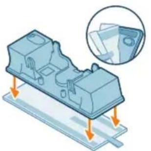
Illustration of an eye with warning symbols (no text or labels)

Isometric illustration of a mechanical component with arrows indicating assembly or movement, and a magnified inset showing a card being inserted (no text or symbols present)

5 Firmly close the water container.

3D illustration of a robotic arm interacting with a base platform (no text or symbols)

Warning: Before using any accessory, do not vacuum water or other liquids.

Using the nozzle

1 Attach the nozzle directly to the handheld vacuum.

Illustration of a hand holding a small mechanical component on a staircase, with an inset showing a textured surface (no text or symbols)

2 Rinse the mop pad under running water and wash it by hand or in the washing machine.

Illustration of a car interior with a faucet and a green valve, no text or symbols present.

7 Be careful not to lose the container lid during storage. Hang the microfiber mop pad and let it dry.

Illustration of hands sorting and pouring granular material into a trash bin (no text or symbols)

8 Wipe the cleaned dust container and cyclone dry.

Diagram showing two views of a cylindrical object with an arrow indicating direction, no text or symbols present.

Diagram of a mechanical device with a downward arrow indicating force or direction (no text or symbols present)

Diagram of a chemical apparatus with labeled parts and directional arrows indicating flow or movement

OFF ①

2 Hold the button on the side of the nozzle with one hand and remove the brush with the other hand.

Illustration of hands using scissors to cut a blue object with coiled lines.

Maintenance of the small turbo brush (only XC5141 and XC5142)

XV1651/01

Battery XV1653/01

3D diagram of a plastic container with an arrow indicating direction.

XV1653/01

Microfiber mop pad XV1630/01

3D illustration of a rectangular electronic component with a blue internal structure and an orange arrow indicating direction.

XV1630/01

Note: Replace the filter and microfiber mop pad every 6 months to ensure maximum performance.

1 Turn the wall mount upside down and detach the handle. Position the charging connector so that the metal part is visible and facing upright at the front of the wall mount.

Diagram illustrating a door lock mechanism with labeled components and directional arrows indicating motion or movement.

2 Close the handle. Make sure the handle is locked and you hear a "CLICK" sound.

125 ± 3 cm

3 Securely attach the wall mount to the desired position on the wall and make sure the lowest screw holes for wall mounting are approximately 125 cm from the floor.

Caution: Be careful when drilling holes in the wall to attach the wall mount to avoid the risk of electric shock.

Illustration of a vacuum cleaner with a magnified inset showing the device's internal structure (no text or symbols present)

Note: Make sure the placement of the wall mount allows the entire appliance to hang on the wall so that the nozzle does not touch the floor.

Mechanical assembly diagram showing two rotating components with arrows indicating motion (no text or labels)

4 Once you have determined the optimal position and height for storing and charging the appliance, firmly tighten the screws to secure the wall mount.

Preparation for use

Illustration of a device with a magnified view showing internal components and heat distribution (no text or symbols)

Note: You can also place the handle on a flat, stable surface and connect the charging cable directly to the appliance.

Diagram showing a cable with a connector and an inset magnified view of the plug (no text or symbols)

Note: Another option is to place the battery on a flat, stable surface and connect the charging cable directly to the battery.

graph TD A["Gear Icon"] --> B["Circle Icon"] style A fill:#f9f,stroke:#333 style B fill:#bbf,stroke:#333 note right of A: 4 hrs

2 Connect the tube to the nozzle. Confirm the connection by hearing a click when you attach it.

Vacuuming floors made of soft and hard materials

Diagram of a device control panel with a blue button labeled '①' and an orange arrow pointing to it (no text or symbols beyond the label)

2 Use the power selection button to switch between three different power settings: eco mode, normal mode, turbo mode.

Eco Normal TurboIllustration of a blue vacuum cleaner with motion lines indicating airflow (no text or symbols)

Illustration of a blue vacuum cleaner emitting exhaust flames (no text or symbols)

Illustration of a blue vacuum cleaner emitting exhaust smoke (no text or symbols)

Illustration of a person using a vacuum cleaner to clean or walk (no text or symbols present)

3 You can use the vacuum cleaner to clean hard or soft floor surfaces.

Safety warning illustration showing a person using a vacuum cleaner to clean water, with warning symbols and a red 'X' indicating no need.

Warning: Do not vacuum water or any other liquid.

Illustration of a human eye with warning symbols (no text or labels)

A Caution: Do not look directly into the LED lights or point them at anyone's eyes. The LED light is very bright.

Vacuuming while mopping hard floors

A Caution: Use the water tank only on hard floors with a waterproof surface (such as linoleum, tiles, or lacquered parquet) and stone floors (such as marble). If your floor is not treated to be waterproof, check with the manufacturer whether you can use water to clean it. Do not use the water tank on hard floors where the waterproof layer is damaged.

i Note: Do not use the water tank to clean carpets.

3D illustration of a mechanical component with arrows indicating assembly or movement, and a magnified inset showing a close-up of a sheet of paper (no text or symbols present)

2 Attach the microfiber cleaning pad under the water tank. Align the Velcro strips under the water tank behind the cloth.

MAX 50 °C

3 Open the rubber cap on top of the water tank. Fill the tank with water, making sure the water temperature does not exceed 50 °C.

10 ml

6 Connect the prepared water tank to the water nozzle and you are ready to start. For proper use, it is important that the tank is firmly placed on the nozzle wheels when in the correct position.

Illustration of a person using a vacuum cleaner on tiled floor, with motion arrows indicating movement (no text or symbols)

i Note: The water module is not suitable for use on soft floors such as carpets.

Illustration showing a person using a vacuum cleaner with warning symbols and a red 'X' indicating a water drop.

2 You can use the mini turbo brush for standard cleaning, for example, of soft surfaces like beds and sofas. You can adjust the power setting to suit your cleaning needs. 3 You can use the mini turbo brush for additional thorough cleaning, for example, for vacuuming pet hair or cleaning small dirt spots, like spilled bread crumbs. You can adjust the power setting to suit your cleaning needs.

2 You can use the long crevice nozzle for cleaning narrow corners or hard-to-reach places. You can adjust the power setting to suit your cleaning needs.

Illustration of a handheld device with orange arrows indicating motion or force, showing internal components and movement (no text or symbols).

Using the combined nozzle

1 To attach the combined nozzle, insert a tube or handle into it.

Illustration of a mechanical component with a wire and a spiderweb, showing three different states of assembly (no text or symbols present).

2 The combined nozzle is designed for cleaning window frames, curtains, or cobwebs, with adjustable brush release and lighting settings.

After use – Maintenance

i Note: Remove the dust container while holding the appliance upright to avoid spilling dirt.
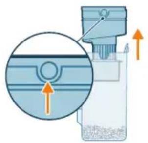
Diagram of a mechanical device with an inset showing a component and directional arrows (no text or symbols).

3 Hold the two recessed circles on the side of the cyclone chamber. Remove the cyclone chamber from the dust container by lifting it out.

Illustration of a plastic bag pouring granular material into a trash bin (no text or symbols).

4 Empty the collected dust from the dust container into a waste bin.

Diagram of a mechanical device with an arrow indicating downward motion (no text or symbols present).

5 Put the cyclone chamber back into the dust container. Make sure the two parts are aligned: the two semicircles must be connected to each other.

Diagram of a laboratory filtration or separation device with labeled components and directional arrows indicating flow or movement.

6 Put the assembled container back. First align the side with the filter on the container before attaching it.

Illustration of a mechanical component with an arrow indicating upward motion, alongside a magnified inset showing a card or wallet (no text or symbols present).

2 Rinse the cleaning pad under the tap and wash it by hand or in a washing machine.

Illustration of a faucet and a plastic housing component with a green base, no text or symbols present.

5 Properly close the water tank and shake it to remove any remaining detergent.

Isometric illustration of a mechanical component with a faucet and a green base, no text or symbols present.

6 Empty the water tank and leave it open to dry.

Illustration of a laundry piece with a warning sign and hanging clothes (no text or symbols)

7 Make sure the cap is not unscrewed during storage. Hang the microfiber cleaning pad to dry.

i Note: We recommend replacing the microfiber cleaning pad every 6 months (accessory XV1630).

Periodic maintenance

Dust collection system maintenance

Illustration of hands pouring liquid into a trash bin with scattered particles (no text or symbols)

3 Empty the filter housing and foam filter over a waste bin.

i Note: be sure to thoroughly clean the filter housing by firmly tapping it over a trash can until no more dust comes out of the filter housing.

Illustration of a faucet pouring liquid into a container with a green checkmark indicating water level (no text or symbols)

4 Rinse the foam filter under running tap water.

Illustration of a hand holding a blue object with green droplets, no text or symbols present

5 Squeeze the foam filter until clean water starts to come out of it.

i Note: for best cleaning results, let water run through the filter with the dirtier side facing down, to rinse out dust that has penetrated deep.

7 For thorough maintenance, clean the dust container and cyclone chamber under running water or in warm soapy water.

Illustration of a hand cleaning a small object with a cylindrical component nearby (no text or symbols)

8 Wipe dry the cleaned dust container and cyclone chamber.

9 Insert the foam filter into the filter housing.

Diagram of a mechanical device with a downward arrow indicating force or direction (no text or symbols present)

10 Put the filter back into the dust container.

Diagram of a chemical reactor with labeled components and flow indicators

11 Put the assembled container back. First align the side with the filter on the container before attaching it.

i Note: After maintenance, always check that the filter is assembled in the appliance before use.

OFF ①

Nozzle maintenance

1 Always switch off the appliance before cleaning the nozzle brush.

Technical diagram of a mechanical device with numbered components and directional arrows indicating motion or flow.

2 Hold the button on the side of the nozzle with one hand while removing the brush with the other.

Illustration of hands using scissors to cut a blue object with coiled lines (no text or symbols)

3 Carefully remove tangled hair from the brush. You can use scissors to make removing dirt easier.

Diagram of a mechanical component with a cylindrical shaft and housing, showing an upward force arrow (no text or symbols)

4 Remove the side cover.

Illustration of a hand holding a cylindrical object with an arrow indicating direction (no text or symbols)

5 Separate the hair that has become tangled in the brush.

Diagram of a mechanical component with a gear and housing, showing internal structure and motion direction (no text or symbols)

6 Replace the cover.

Mechanical assembly diagram showing a gear and motor components (no text or labels)

Maintenance of the mini turbo brush (only models XC5141 and XC5142)

2 Remove all dirt from the brush by hand or with scissors.

Diagram illustrating a lock mechanism with labeled components and lock states

3 When putting the brush back, simply align it back into its original position. Check that the inner end is aligned. Turn the brush clockwise to secure it. When the brush is properly assembled, you will hear a "CLICK" sound.

Illustration of a mechanical component with a green base and a faucet, no text or symbols present

6 Rinse and remove any remaining liquid from the water tank.

Illustration of a three-pin electrical connector with green checkmarks indicating status (no text or symbols)

Replacement filter XV1651/01

Illustration of a box containing a bag with an upward arrow, no text or symbols present

XV1651/01

Battery XV1653/01

3D diagram of a mechanical component with an arrow indicating direction (no text or symbols)

XV1653/01

Microfiber cleaning pad XV1630/01

3D illustration of a rectangular electronic component with a blue internal structure and an orange arrow indicating direction (no text or symbols)

XV1630/01

PHILIPS 5000 series XC5141 - Maintenance of the mini turbo brush (only models XC5141 and XC5142) - 7

The battery level is low and needs to be charged. Charge the appliance and battery using the recommended charging methods.

Troubleshooting

This chapter briefly lists the most common problems you may encounter.

Illustration of a blue vacuum cleaner emitting exhaust flames, with no text or symbols present.

Illustration of a blue vacuum cleaner emitting exhaust smoke (no text or symbols).

Illustration of a person using a vacuum cleaner to clean or walk (no text or symbols present)

Illustration of a mechanical component with arrows indicating assembly or movement, and an inset showing a close-up of a sheet of paper (no text or symbols present)

Illustration of hands sorting and removing a trash bin with granular material.

Diagram showing two views of a cylindrical object with an arrow indicating direction (no text or symbols).

Diagram of a mechanical device with a downward arrow indicating force or direction (no text or symbols).

Diagram of a chemical apparatus with labeled parts and directional arrows indicating flow or movement.

OFF ①

4 Rinse the foam filter under the tap.

Illustration of a hand holding a cylindrical object with an arrow indicating direction (no text or symbols).

6 Clean the cover.

Mechanical assembly diagram showing a gear and motor components with an orange arrow indicating motion direction (no text or labels).

Maintenance of the mini turbo brush (only XC5141 and XC5142)

XV1651/01

Battery XV1653/01

3D diagram of a plastic container with an arrow indicating direction. No text or symbols.

XV1653/01

Microfiber mop pad XV1630/01

3D illustration of a rectangular electronic component with a blue internal structure and an orange arrow indicating direction. No text or symbols.

XV1630/01

Diagram of a mechanical or electrical component with two rotating arms and directional arrows indicating motion (no text or symbols).

MAX 35°C MIN 10°C

Illustration of a vacuum cleaner emitting exhaust smoke, with no text or symbols present.

Illustration of a blue vacuum cleaner emitting orange smoke, with no text or symbols present.

Illustration of a person using a vacuum cleaner to clean or walk (no text or symbols present).

3D illustration of a mechanical component with arrows indicating assembly or movement, and a magnified inset showing a close-up of a sheet of paper (no text or symbols present).

Illustration of hands pouring liquid into a trash bin with scattered particles (no text or symbols).

4 Rinse the foam filter under the tap.

Illustration of a hand holding a blue object with green droplets (no text or symbols).

Illustration of a glass beaker with liquid being inverted, next to a water bottle and a vertical column of water (no text or symbols).

MAX 50 °C

Diagram illustrating a mechanical device with labeled parts and motion arrows, including section 1 showing a close-up of the component.

3D diagram of a mechanical component with a circular annotation indicating 12 hours (no text or symbols on the object itself).

XV1651/01

Battery XV1653/01

3D diagram of a plastic container with an arrow indicating direction (no text or symbols).

XV1653/01

Microfiber mop pad XV1630/01

3D illustration of a rectangular electronic component with a blue internal structure and an orange arrow indicating direction (no text or symbols).

XV1630/01

adapter is used.

Illustration of a vacuum cleaner emitting exhaust flames, with no text or symbols present.

Illustration of a blue vacuum cleaner emitting exhaust smoke (no text or symbols)

Illustration of a person using a vacuum cleaner to clean or walk (no text or symbols present)

3D illustration of a mechanical component with arrows indicating assembly or movement, and an inset showing a close-up of a sheet of paper (no text or symbols present)

Illustration of hands sorting and dumping material into a trash bin (no text or symbols)

Diagram showing two views of a cylindrical object with an arrow indicating direction, no text or symbols present.

Diagram of a mechanical device with a downward arrow indicating force or direction (no text or symbols present)

Diagram of a chemical apparatus with labeled parts and directional arrows indicating flow or movement

OFF ①

4 Remove the side cover.

Illustration of a hand holding a cylindrical object with an arrow indicating direction (no text or symbols)

6 Replace the cover.

Mechanical assembly diagram showing a gear-like component with an arrow indicating motion (no text or symbols)

Illustration of a beaker pouring liquid from a piping bag into a water bottle, next to a vertical water tank (no text or symbols)

XV1651/01

Battery XV1653/01

3D diagram of a mechanical component with an arrow indicating direction (no text or symbols)

XV1653/01

XV1630/01

Illustration of a vacuum cleaner emitting exhaust smoke, with no text or symbols present.

Illustration of a blue vacuum cleaner emitting orange spray, with no text or symbols present.

Illustration of a person using a vacuum cleaner to clean or walk (no text or symbols present).

3D illustration of a mechanical component with arrows indicating assembly or movement, and a magnified inset showing a close-up of a sheet of paper, no text or symbols present.

Water tank maintenance

Illustration of hands pouring liquid into a trash bin with scattered particles.

Water tank maintenance

XV1651/01

Battery XV1653/01

3D diagram of a mechanical component with an arrow indicating direction. No text or symbols.

XV1653/01

Microfiber mopping cloth XV1630/01

3D illustration of a rectangular electronic component with a blue internal structure and an orange arrow indicating direction. No text or symbols.

XV1630/01

Illustration of a blue vacuum cleaner emitting exhaust flames (no text or symbols).

Illustration of a blue vacuum cleaner emitting orange spray (no text or symbols).

Illustration of a person using a vacuum cleaner to clean or walk (no text or symbols).

Isometric illustration of a mechanical component with arrows indicating assembly or movement, and a magnified inset showing a card being inserted.

Illustration of a hand pressing down on a cylindrical component with an arrow indicating rotation, no text or symbols.

Safety warning icons showing a device with a warning symbol and a washing machine without a prohibition sign.

Diagram showing a cylindrical object with labeled parts and an arrow indicating direction, possibly illustrating a physical or engineering concept.

Diagram of a mechanical device with an arrow indicating downward motion, no text or symbols present.

Diagram of a chemical reactor with labeled components and flow indicators.

Illustration of hands using scissors to cut a wire on a mechanical component, no text or symbols.

Diagram of a mechanical component with spring-like grooves and a rotating shaft, showing an upward arrow (no text or symbols)

Illustration of a hand holding a cylindrical object with a blue lens, showing an upward arrow (no text or symbols)

XV1651/01

Battery XV1653/01

3D diagram of a plastic container with an arrow indicating direction (no text or symbols)

XV1653/01

XV1630/01

Illustration of a blue vacuum cleaner emitting exhaust flames (no text or symbols)

Illustration of a blue vacuum cleaner emitting orange smoke, with no text or symbols present.

Illustration of a person using a vacuum cleaner to lift a person's legs (no text or symbols present)

Isometric illustration of a mechanical component with arrows indicating assembly or movement, and a magnified inset showing a card being inserted.

Illustration of a medical or laboratory procedure showing a tool interacting with a blue tool, with an arrow indicating motion.

Illustration of a medical or laboratory procedure showing a pipette inserted into a container with a magnified inset.

Illustration of a handheld device with orange arrows indicating motion or force, showing internal components and movement.

Illustration of a cable being inserted into a wire, showing three different states of the wire.

Diagram showing two views of a cylindrical object with an arrow indicating direction, no text or symbols present.

Diagram of a mechanical device with a downward arrow indicating force or direction, no text or symbols present.

Diagram of a chemical apparatus with labeled parts and directional arrows indicating flow or movement.

OFF ①

XV1651/01

Battery XV1653/01

3D diagram of a white plastic container with an orange arrow indicating direction.

XV1653/01

XV1630/01

Illustration of a blue vacuum cleaner emitting exhaust flames.

Illustration of a blue vacuum cleaner emitting orange spray.

Illustration of a person using a vacuum cleaner to lift a person's legs.

3D illustration of a mechanical component with arrows indicating assembly or movement, and a magnified inset showing a close-up of a sheet of paper.

Illustration of a medical or laboratory procedure showing a pipette inserted into a cylindrical container with a magnified inset.

Illustration of hands pouring liquid into a trash bin with scattered particles.

XV1651/01

Battery XV1653/01

3D diagram of a plastic container with an arrow indicating direction (no text or symbols)

XV1653/01

XV1630/01

Illustration of a blue vacuum cleaner emitting exhaust flames.

Illustration of a blue vacuum cleaner emitting orange spray.

Illustration of a person using a vacuum cleaner to clean or stand.

Isometric illustration of a mechanical component with arrows indicating assembly or movement, and a magnified inset showing a document.

Illustration of hands sorting and dumping material into a trash bin, no text or symbols.

Diagram showing two views of a cylindrical object with an arrow indicating direction, no text or symbols present.

Diagram of a mechanical device with a downward arrow indicating force or direction, no text or symbols present.

Diagram of a chemical apparatus with labeled parts and directional arrows indicating flow or movement.

OFF ①

XV1651/01

Battery XV1653/01

3D diagram of a plastic container with an arrow indicating direction (no text or symbols)

XV1653/01

XV1630/01

125 ± 3 cm

Illustration of a vacuum cleaner next to a floor-mounted device, with a magnified inset showing the device's interior detail (no text or symbols present)

Pure mechanical diagram showing two rotating components with arrows indicating motion direction (no text or symbols)

Mechanical assembly diagram showing a component being inserted into a base (no text or symbols visible)

Illustration of a person using a vacuum cleaner on tiled floor, with orange arrows indicating motion (no text or symbols)

Illustration of a person using a vacuum cleaner on a patterned rug, with a red X mark indicating no text or symbols.

Illustration showing a person using a vacuum cleaner with warning symbols and a red 'X' indicating no need or failure.

Using the suction nozzle

Illustration of a mechanical tool interacting with a cylindrical component, showing a magnified inset (no text or symbols).

Illustration of a medical or laboratory device with arrows indicating force or movement, showing internal components (no text or symbols).

Illustration of a medical or surgical tool interacting with a wire, showing three different views (top: finger, middle: spiderweb, bottom-right: magnifying glass).

Diagram of a handheld vacuum cleaner with an inset showing the device's rotation (no text or symbols present).

Illustration of a faucet pouring liquid into a circular tank with a green checkmark indicating water level.

XV1651/01

3D diagram of a plastic container with an arrow indicating direction.

XV1653/01

XV1630/01

1 Press the on/off button to start the product.

3 The vacuum cleaner can be used on both hard and soft floors.

Illustration showing a person using a vacuum cleaner with warning symbols and a red X mark indicating no need or failure.

Warning: Do not suck up water or other liquids.

Illustration of an eye with warning symbols and a robot holding a scroll, no readable text present.

5 Close the water tank.

Mechanical assembly diagram showing a robotic arm interacting with a base component, no text or symbols visible.

Note: This water outlet module is not suitable for soft floors such as carpets.

Illustration showing a person using a vacuum cleaner with warning symbols and a red 'X' indicating a water drop.

Warning: This water outlet module must not be used to suck up puddles.

Tips and other important information

Illustration of a hand holding a tool on stairs, with a magnified inset showing a textured surface, no text or symbols.

4 Empty the dust collected in the dust container into a trash bin.

Diagram of a mechanical device with an arrow indicating downward motion (no text or symbols present)

Dust management system maintenance

2 Remove the washable sponge filter from the plastic filter mesh box.

Illustration of hands sorting and removing a trash bin with granular material (no text or symbols)

4 Rinse the sponge filter under the tap.

Illustration of a hand holding a blue object with green droplets, no text or symbols present

5 Squeeze the sponge filter until clean water comes out of it.

Safety warning icon showing a device with warning symbol and a washing machine without a prohibition sign

Diagram showing two blue circular objects with a central orange arrow, one enclosed in a circle (no text or symbols)

Diagram of a mechanical device with an arrow pointing to a component (no text or symbols present)

Diagram of a laboratory filtration setup with labeled components and directional arrows indicating flow or movement.

8 Dry the cleaned dust container and cyclone filter.

4 Remove the side cover.

Illustration of a hand holding a cylindrical object with an arrow indicating direction (no text or symbols).

5 Remove any tangled hair from the nozzle brush.

Illustration of a cylindrical mechanical component with a separate inset showing a circular component and an arrow indicating direction (no text or symbols).

6 Put the side cover back on.

Mechanical gear assembly diagram showing a chain drive and housing components (no text or labels).

8 Lock the nozzle brush until you hear a click.

Note: Check and remove any dirt around the nozzle wheels.

Diagram illustrating a lock mechanism with labeled components and directional arrows indicating process flow.

2 Use your hands or scissors to remove dirt from the brush.

Diagram illustrating a door lock mechanism with labeled parts and lock symbol.

Water tank maintenance

The water tank needs to be descaled once a month to prevent limescale buildup.

1 Add a small amount of descaling solution to the measuring cup.

Illustration of a beaker with liquid being inverted and a water bottle beside it (no text or symbols).

2 Add an appropriate amount of water to the measuring cup.

MAX 50 °C

3 Pour the mixed solution into the water tank.

Diagram illustrating a mechanical device with labeled parts and motion arrows, showing two states of movement.

4 Close the water tank and shake the body to mix the descaling solution.

12 hrs

XV1651/01

Battery XV1653/01

3D diagram of a plastic container with an arrow indicating direction, no text or symbols.

XV1653/01

Microfiber cleaning cloth XV1630/01

3D illustration of a rectangular block with a blue internal channel and an orange arrow pointing downward, no text or symbols.

XV1630/01

The adapter is not unplugged.

First unplug the adapter, then restart the product.

Signal Signal meaning

1 Press the switch button to turn on the product.

Illustration of a blue vacuum cleaner emitting exhaust flames, with no text or symbols present.

Illustration of a blue vacuum cleaner emitting exhaust smoke (no text or symbols).

Illustration of a person using a vacuum cleaner to clean or walk (no text or symbols present).

Warning: Do not use to pick up water or other liquids.

Illustration of a human eye with warning symbols (no text or labels).

MAX 50 °C

5 Close the water tank.

Mechanical assembly diagram showing a clamping device pressing down on a base (no text or symbols visible).

Warning: Do not use the wet mopping module to handle puddles.

Tips and other important information

Illustration of a hand holding a small mechanical component on stairs, with an inset showing a crack (no text or symbols).

Illustration of a handheld vacuum cleaner emitting exhaust plume (no text or symbols).

Diagram illustrating a hair cleaning or hair repair process with labeled components and visual examples of the bed and cat.

Illustration of a medical or laboratory procedure showing a tool interacting with a blue tool, with an arrow indicating motion (no text or symbols present).

Use the nozzle

1 Attach the nozzle directly to the handheld vacuum cleaner.

Using the combination tool

4 Empty the dust collected in the dust bin into a trash can.

Diagram of a mechanical device with a downward arrow indicating force or direction (no text or symbols present)

3 Empty any residual water from the water tank.

Illustration of a mechanical component with a green base and a faucet, no text or symbols present

MAX 50 °C

4 Fill the water tank with water.

Diagram illustrating a mechanical device with labeled parts and motion arrows, showing two states of movement.

6 Empty the water tank and leave it open to dry.

Diagram showing a device with an alert icon and a hanging clothes, likely illustrating a safety or cleaning concept.

1 Pull up the filter to remove it from the dust bin.

Illustration of a hand pressing down on a cylindrical component with an arrow indicating rotation (no text or symbols)

3 Tap the filter box and foam filter over a trash can.

4 Rinse the foam filter under a faucet.

Illustration of a hand holding a blue object with a droplet falling (no text or symbols)

10 Reinstall the filter into the dust bin.

Diagram of a chemical apparatus with labeled parts and directional arrows indicating flow or movement.

4 Remove the side cover.

Illustration of a hand holding a cylindrical object with an arrow indicating direction (no text or symbols).

5 Remove hair tangled in the brush bristles.

Illustration of a cylindrical mechanical component with a separate inset showing a separate view (no text or symbols).

6 Reattach the cover.

Mechanical assembly diagram showing gear and motor components (no text or labels).

Illustration of a hand holding a cylindrical object with an arrow indicating upward motion (no text or symbols).

Diagram illustrating a lock mechanism with labeled components and lock symbol.

Illustration of a beaker with liquid being inverted and a water bottle beside a water tap (no text or symbols).

2 Pour the correct amount of water into the measuring cup.

MAX 50 °C

3 Pour the mixture into the water tank.

Diagram illustrating a mechanical device with labeled parts and motion arrows, showing two states of movement.

6 Rinse the water tank and pour out any remaining liquid.

3D diagram of a rectangular electronic component with three ports and three green checkmarks indicating status (no text or symbols)

XV1651/01

Battery XV1653/01

3D diagram of a blue plastic container being inserted into a white housing, with an orange arrow indicating direction (no text or symbols)

XV1653/01

Microfiber mopping pad XV1630/01
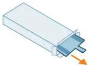
3D illustration of a rectangular electronic component with a small internal structure and an orange arrow pointing to it (no text or symbols)

XV1630/01

Diagram showing mechanical assembly with labeled parts and directional arrows indicating motion or movement

Illustration of a blue vacuum cleaner emitting exhaust flames.

Illustration of a blue vacuum cleaner emitting exhaust smoke.

Illustration of a person using a vacuum cleaner to clean or walk.

3D illustration of a mechanical component with arrows indicating assembly or force direction, and a magnified inset showing overlapping sheeting.

5 Close the aqua tank properly.

Mechanical assembly diagram showing a robotic arm interacting with a base.

Using the mini turbo brush

Aqua tank maintenance

Regular maintenance

Illustration of a hand inserting a component into a device, showing airflow direction, no text or symbols.

Illustration of a hand holding a cylindrical object with an arrow indicating rotation, no text or symbols.

Illustration of hands sorting and removing a trash bin with granular material, no text or symbols.

4 Remove the side cap.

Illustration of a hand holding a cylindrical object with an arrow indicating direction (no text or symbols)

6 Put the cap back on.

Mechanical assembly diagram showing a gear and motor components with an orange arrow indicating motion direction (no text or labels)

Illustration of a beaker with liquid being inverted and a water bottle inside a container (no text or symbols)

XV1651/01

Battery XV1653/01
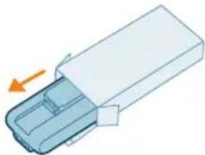
3D diagram of a plastic container with an arrow indicating direction (no text or symbols)

XV1653/01

XV1630/01

Table of contents Click a title to access it
Manual assistant
Powered by Anthropic
Waiting for your message
Product information

Brand : PHILIPS

Model : 5000 series XC5141

Category : Vacuum Cleaner