
TDD1-20 - Barbecue DCS - Free user manual and instructions
Find the device manual for free TDD1-20 DCS in PDF.

| Product Type | Double Outdoor Storage Drawer |
| Brand | DCS |
| Model | TDD1-20 |
| Product Height | 556 mm (21 7/8 in) |
| Product Width | 516 mm (20 5/16 in) |
| Product Depth (chassis) | 585 mm (23 in) |
| Front frame depth (excluding handle) | 51 mm (2 in) |
| Estimated Weight | 25 kg (55 lb) |
| Material | Stainless Steel |
| Number of Drawers | 2 |
| Maximum Load Capacity | 50 kg (110 lb) per drawer |
| Power Supply | None (mechanical) |
| Installation Type | Flush mount or overlay |
| Introduction | For outdoor storage of barbecue equipment and accessories |
| Main Functions | Storage of gas bottles, utensils, charcoal, etc. |
| Care and Cleaning | Clean with a soft cloth and soapy water. Do not use abrasive products. |
| Safety | Sharp edges, risk of cuts and crushing. Use handles. |
| Warranty | 2 years parts and labor |
| Spare Parts and Repairability | Genuine parts available from Fisher & Paykel service center |
Frequently Asked Questions - TDD1-20 DCS
User questions about TDD1-20 DCS
0 question about this device. Answer the ones you know or ask your own.
Ask a new question about this device
Download the instructions for your Barbecue in PDF format for free! Find your manual TDD1-20 - DCS and take your electronic device back in hand. On this page are published all the documents necessary for the use of your device. TDD1-20 by DCS.
USER MANUAL TDD1-20 DCS
INSTALLATION INSTRUCTIONS
Outdoor Storage
TDS1-20, TDD1-20, TDT1-20, TB1-20, DP1-42 & BC25 models
US CA

590615B 08.14
① SAFETY AND WARNINGS
WARNING!

Cut hazard
Take care - panel edges are sharp.
Failure to use caution could result in injury or cuts.
WARNING!

Crush hazard
Closing drawers may cause injury to your hands or fingers.
Always close or open drawers using their handles.
Be sure to keep hands away from drawer edges when opening or closing drawers.
failure to use caution could result in injury or cuts.
IMPORTANT SAFETY INSTRUCTIONS!
- Do not remove permanently affixed labels, warnings, or plates from the product. This may void the warranty.
Please make this information available to the person installing the appliance as it could reduce your installation costs.
Please leave these instructions with the appliance. Inform the customer to retain for future reference and for the local inspectors' use. - Failure to install the appliance correctly could invalidate any warranty or liability claims.
- Only genuine replacement parts may be used for servicing the appliance. These are available from your nearest Fisher & Paykel Service Center.
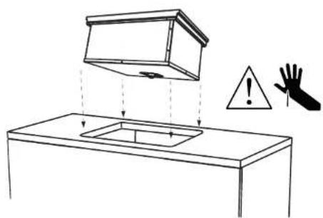
■ the countertop is square and level and no structural members interfere with space requirements - Do Not store or use gasoline or other flammable vapors and liquids inside or in the vicinity of this or any other appliance.
An LP cylinder not connected for use shall not be stored inside or in the vicinity of this unit.
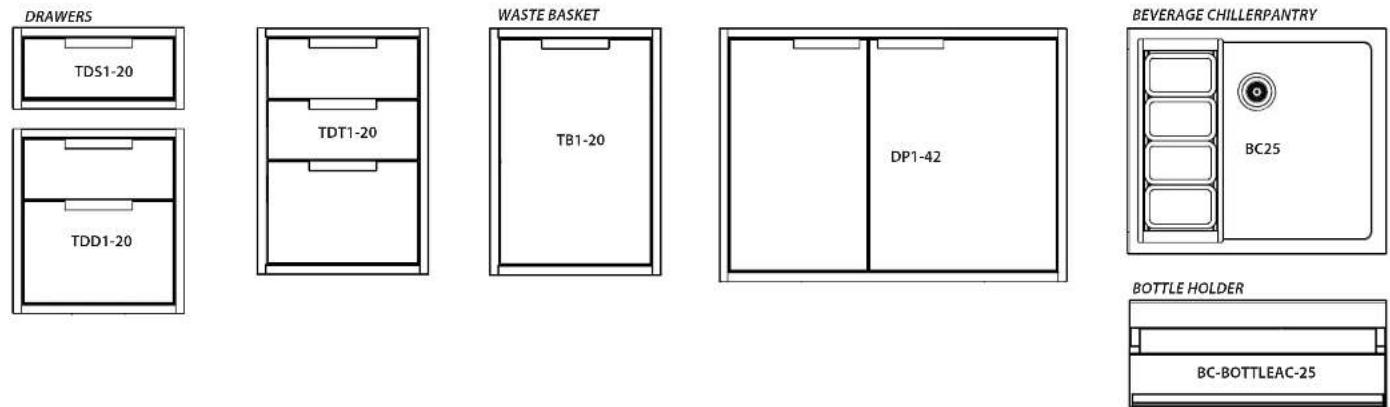
② MODEL LINE UP
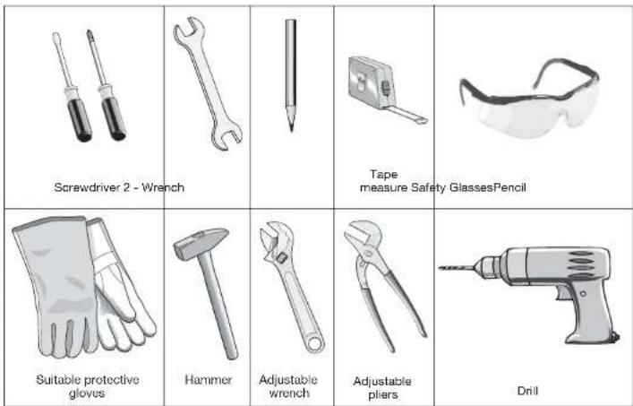
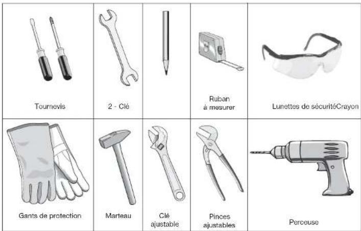
③ TOOLS REQUIRED (NOT SUPPLIED)
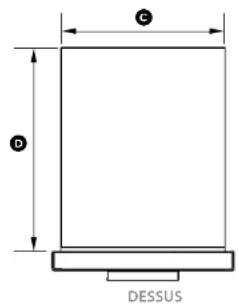
④ PRODUCT DIMENSIONS - DRAWERS, PANTRY & WASTE BASKET
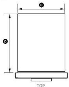
text_image
C D TOPTB1-20 model shown for illustration purposes
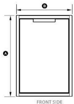
text_image
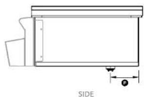
A B FRONT SIDE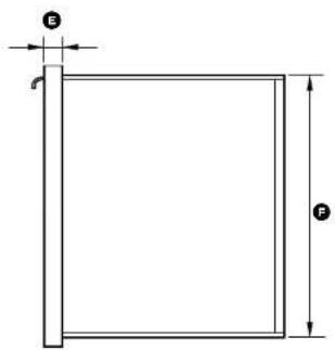
text_image
E FProduct dimensions Inches (mm)
| TDS1-20 | TDD1-20 | TDT1-20 | TB1-20 | DP1-42 | ||
| A | overall height of product | 9 5/8" (245) | 21 7/8" (556) | 29 1/8" (740) | 29 1/8" (740) | 30 1/2" (775) |
| B | overall width of product | 20 5/16" (516) | 20 5/16" (516) | 20 5/16" (516) | 20 5/16" (516) | 42" (1066) |
| C | width of chassis | 18 1/2" (469) | 18 1/2" (469) | 18 1/2" (469) | 18 1/2" (469) | 40" (1016) |
| D | depth of chassis 23" (585) 23" (585) 23" (585) 23" (585) | 23 1/16" (601) | ||||
| E | depth of front frame (excluding handle) | 2" (51) | 2" (51) | 2" (51) | 2" (51) | 2" (51) |
| F | height of chassis | 8 5/16" (210) | 20 1/2" (520) | 27 1/3/16" (705) | 27 1/3/16" (705) | 29" (736) |
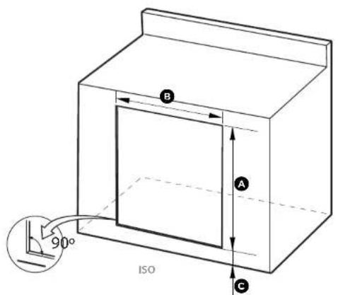
⑤ CABINETRY DIMENSIONS (PROUD INSTALLATION) - DRAWERS, PANTRY & WASTE BASKET

text_image
B A 90° ISO C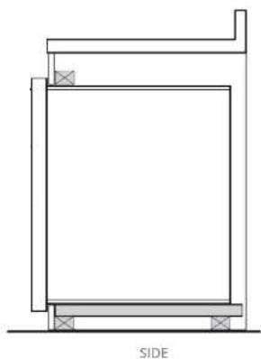
natural_image
Architectural cross-section diagram of a building facade with labeled side (SIDE), showing structural layers and supports (no text or symbols beyond label)Cabinetry dimensions inches (mm)
| TDS1-20 | TDD1-20 | TDT-20 | TBT-20 | DP1-42 | ||
| A | overall height of cutout | 8 7/8" (215) | 20 1/8" (525) | 28" (710) | 28" (710) | 29 3/8" (741) |
| B | overall width of cutout | 18 7/8" (480) | 18 7/8" (480) | 18 7/8" (480) | 18 7/8" (480) | 40 7/8" (1026) |
| C | height from ground to bottom of cutout | min. 1 3/8" (30) | min. 1 3/8" (30) | min. 1 3/8" (30) | min. 1 3/8" (30) | min. 1 3/8" (30) |
⑤ CABINETRY DIMENSIONS (FLUSH INSTALLATION) - DRAWERS, PANTRY & WASTE BASKET
TB1-20 model shown for illustration purposes
text_image
B A 90° ISO C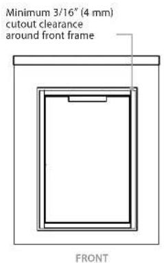
text_image
Minimum 3/16" (4 mm) cutout clearance around front frame FRONT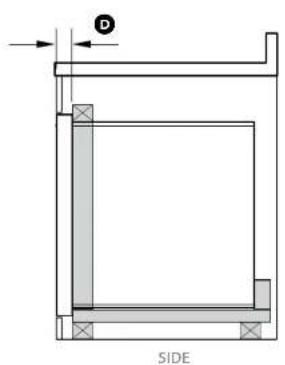
text_image
D SIDE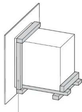
natural_image
Pure technical line drawing of a rectangular frame mounted on a vertical support structure (no text or symbols)A frame should be constructed 2" (51 mm) setback from the front face of the product to both push the product up against and conceal the cutout clearance around the front frame.
Important!
Do not seal the product in with silicone caulk or similar. Doing so will result in the product being difficult to remove for servicing.
Cabinetry dimensions inches (mm)
| TD51-20 | TDD1-20 | TD71-20 | TB1-20 | DP1-42 | ||
| A | overall height of cutout | 9^1/3/_6 ′′(249) | 22^1/8 ′′(560) | 29^3/8 ′′(745) | 29^3/8 ′′(745) | 30^1/3/_6 ′′(779) |
| B | overall width of cutout | 20^1/2 ′′(521) | 20^1/2 ′′(521) | 20^1/2 ′′(521) | 20^1/2 ′′(521) | 42^3/8 ′′(1072) |
| C | height from ground to bottom of cutout | min. 1^3/8 ′′(30) | min. 1^3/8 ′′(30) | min. 1^3/8 ′′(30) | min. 1^3/8 ′′(30) | min. 1^3/8 ′′(30) |
| D | setback for flush installation | 2^(51) | 2^(51) | 2^(51) | 2^(51) | 2^(51) |
⑥ PRODUCT & CABINETRY DIMENSIONS - BEVERAGE CHILLER / BOTTLE HOLDER
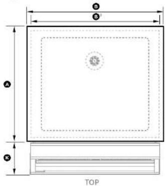
text_image
B B' A K TOP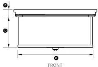
text_image
G D C FRONTWITHOUT BOTTLE HOLDER ACCESSORY
INCLUDING BOTTLE HOLDER ACCESSORY
natural_image
Technical line drawing of a mechanical component with labeled side view (SIDE), showing internal structure and dimension lines (no text or symbols beyond label)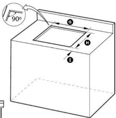
text_image
90° G H I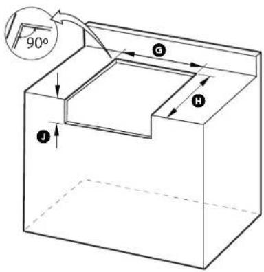
text_image
90° G H IMake sure the countertop is square and level and no structural members interfere with space requirements.
Cabinetry dimensions inches (mm)
BC25
| A | overall depth of product (including lid) | 21 16 " (557) |
| B | overall width of product (including lid) | 26 38 " (670) |
| B^1 | overall width of product (excluding lid) | 25 116 " (636) |
| C | width of chassis | 23 1516 " (608) |
| D | height of chassis (below countertop) | 9 1316 " (249) |
| E | height of frame (including lid) | 2 14 " (57) |
| F | distance from rear of chassis to centre of drain | 5 516 " (142) |
| G | overall width of cutout | 24 316 " (615) |
| H | depth of cutout:without bottle holder accessoryincluding bottle holder accessory | 21 116 " (535)21 116 " (550) |
| I | minimum distance from front of countertop to cutout | 58 " (15) |
| J | height of cutout for bottle holder accessory | 9 78 " (250) |
| K | depth of bottle holder at widest point to front of frame | 6 58 " (168) |
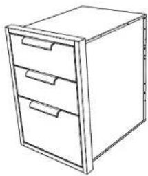
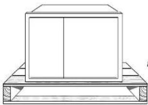
INSTALLING DRAWER UNITS, WASTE BASKET

DISCARD PACKAGING
Model may vary from illustrations shown
natural_image
Line drawing of a three-drawer filing cabinet with drawers (no text or symbols)
Recycle responsibly
Inspect the product(s) to verify that there is no shipping damage.
If any damage is detected, call the shipper and initiate a damage claim.
DCS by Fisher & Paykel is not responsible for shipping damage.
NOTE: Do not discard any packing material until the unit has been inspected.
Operate the drawers to be sure they glide smoothly.
Examine the fronts to be sure there are no dents or scratches or discoloring.

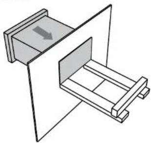
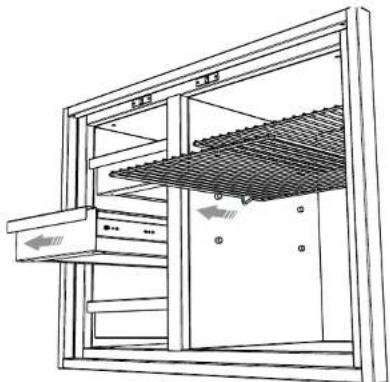
REMOVE ALL DRAWERS TO ACCESS SCREW HOLE LOCATIONS
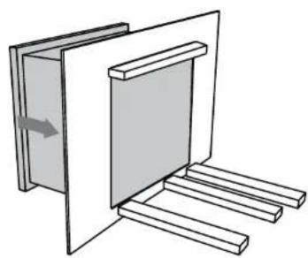
To remove the drawer(s)
1 Remove the drawers by pulling them out until the slider latch is visible.
2 Carefully push the latch down on the left side, while lifting up the latch on the right side.
3 Pull the drawer out of the frame. Note: to prevent damage to surfaces, place the drawers on a stable surface on a protective towel or table cloth.
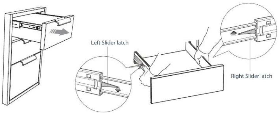
text_image
Left Slider latch Right Slider latch
PREPARE THE CAVITY
- Ensure the cavity is level, square and able to support the weight of the product when full.
- Any cabinet and/or ground preparation must be completed prior to installation.
- All support structures must be constructed of materials resistant to moisture damage.
- Do no use harsh products (acid, solvent, sealers) around this product.
1 Depending on your construction, place either a shelf or at least two (min 2" (51 mm) wide) moisture resistant supports in the cutout. Ensure all support boards are flat and level.
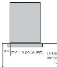
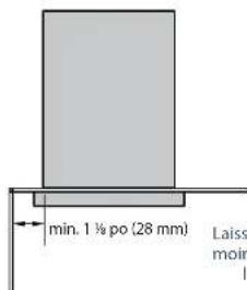
CORNER INSTALLATION
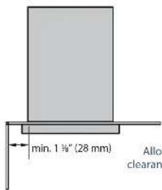
text_image
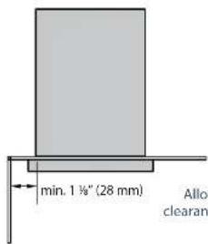
min. 1 ½" (28 mm) Allo clearanAllow min. 1 18 " (28mm) clearance from the cutout to a corner
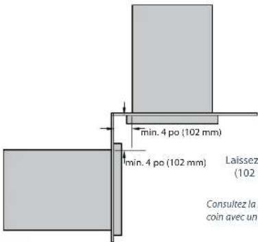
CORNER INSTALLATION WITH TWO PRODUCTS
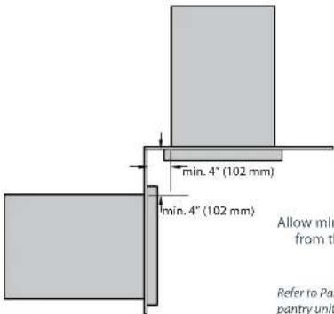
text_image
min. 4" (102 mm) min. 4" (102 mm) Allow min from th Refer to Pan pantry unitAllow min. 4" (102 mm) clearance from the cutout to a corner
Refer to Pantry installation for corner installations with a pantry unit or beverage unit with bottle holder.
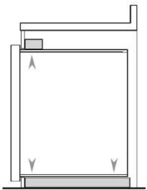
TDS1-20 ONLY
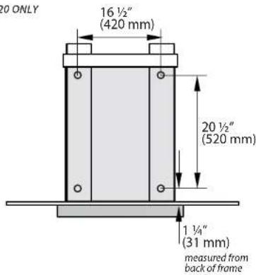
text_image
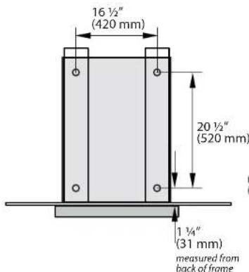
20 ONLY 16 ½" (420 mm) 20 ½" (520 mm) 1 ½" (31 mm) measured from back of frameProvide a support behind the chassis to screw into
text_image
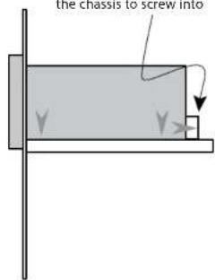
the chassis to screw intoTDD1-20, TDT1-20 & TB1-20 ONLY
text_image
16 ½" (420 mm) 20 ½" (520 mm) 1 ¼" (31 mm) measured from back of frame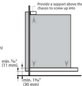
text_image
Provide a support above the chassis to screw up into min. 7½" (11 mm) min. 1¾" (30 mm)
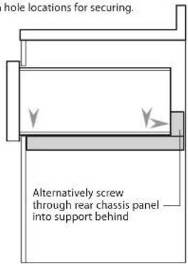
INSERT PRODUCT INTO CAVITY & SECURE
1 With the help of an assistant, lift the unit and slide it into the cabinet cutout along the supports. Adjust for level and fit.
2 Locate the mounting holes (front and rear of base on each side).
Single Drawer TDS1-20 only:
If you find the rear base screw hole locations inaccessible, you may screw through the rear chassis panel into the support behind the unit.
3 Secure the unit using screws suitable for the type of cabinetry materials used. We recommend using all the shown hole locations for securing.
TDS1-20 ONLY
natural_image
Diagram of a mechanical device with two compartments and a directional arrow indicating movement (no text or symbols)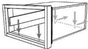
natural_image
Diagram of a rectangular frame with internal horizontal bars and downward arrows indicating force or movement (no text or symbols)Refer to Step 9a for screw mounting hole positions
text_image
hole locations for securing. Alternatively screw through rear chassis panel into support behind
natural_image
Simple line drawing of a rectangular box mounted on a stand (no text or symbols)"DD1-20, TDT1-20 & TB1-20 ONLY
natural_image
Simple line drawing of a door with a handle and two legs, showing an arrow indicating direction (no text or symbols)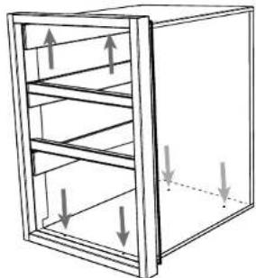
natural_image
Diagram of a multi-tiered storage cabinet with upward and downward arrows indicating internal flow (no text or symbols)Refer to Step 9a for screw mounting hole positions
natural_image
Pure architectural or mechanical diagram showing a rectangular structure with supports and directional arrows, no text or symbols present.
natural_image
Simple line drawing of a rectangular block mounted on a stand, no text or symbols present
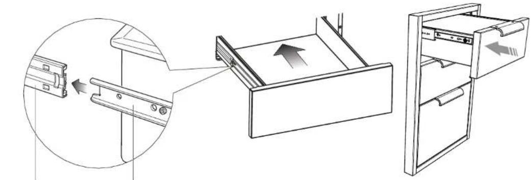
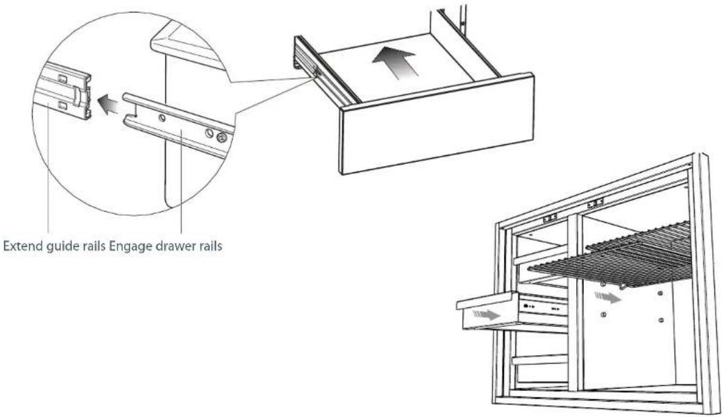
REPLACE ALL DRAWERS
To replace the drawer(s)
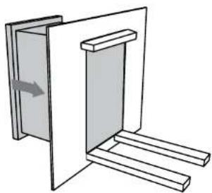
1 Extend both guide rails out.
2 Engage the drawer rails into the guide rails. Pull the guide rails forward until they 'click' into place.
3 Push the drawer all the way in (there will be some resistance) to completely engage the drawer.
natural_image
Diagram showing a door drawer with an open drawer and a separate view of the door handle (no text or symbols present)Extend guide rails Engage drawer rails
INSTALLING PANTRY UNIT

DISCARD PACKAGING
Model may vary from illustrations shown
natural_image
Simple line drawing of a rectangular box placed on a wooden platform (no text or symbols)
Recycle responsibly
Inspect the product(s) to verify that there is no shipping damage.
If any damage is detected, call the shipper and initiate a damage claim.
DCS by Fisher & Paykel is not responsible for shipping damage.
NOTE: Do not discard any packing material until the unit has been inspected.
Operate the drawers and shelves to be sure they glide smoothly.
Examine the fronts to be sure there are no dents or scratches or discoloring.
Exercise caution if fully opening the pantry doors. The outer frame
could mark the door fronts.

REMOVE ALL DRAWERS and SHELVES TO ACCESS SCREW HOLE LOCATIONS
To remove the drawer(s)
1 Remove the drawers by pulling them out until the slider latch is visible.
2 Carefully push the latch down on the left side, while lifting up the latch on the right side.
3 Pull the drawer out of the frame.
Note: to prevent damage to surfaces, place the drawers on a stable surface on a protective towel or table cloth.
natural_image
Technical line drawing of a mechanical or architectural structure with no visible text, numbers, or symbols.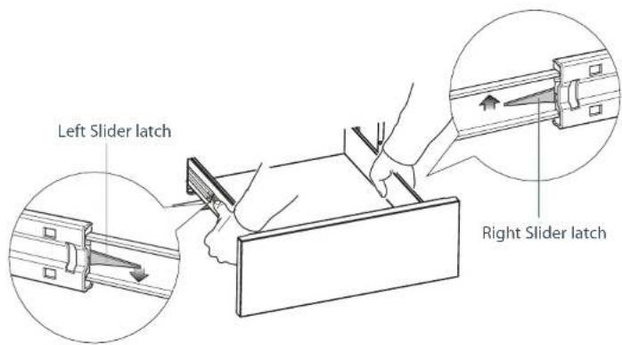
text_image
Left Slider latch Right Slider latch9b PREPARE THE CAVITY
■ Ensure the cavity is level, square and able to support the weight of the product when full.
- Any cabinet and/or ground preparation must be completed prior to installation.
- All support structures must be constructed of materials resistant to moisture damage.
- Do no use harsh products (acid, solvent, sealers) around this product.
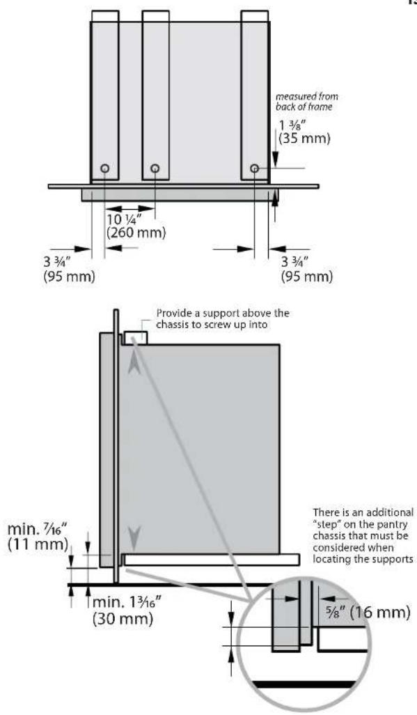
1 Depending on your construction, place either a shelf or at least two (min 2" (51 mm) wide) moisture resistant supports in the cutout, paying special attention to the "step" on the base of the chassis. Ensure all support boards are flat and level.
2 Provide a similar support above the chassis to screw up into as shown.
CORNER INSTALLATIONS
text_image
min. 1 ½" (28 mm) Allo clearanAllow min. 1 18 " (28mm) clearance from the cutout to a corner
CORNER INSTALLATIONS WITH TWO PRODUCTS (INCLUDING PANTRY)
text_image
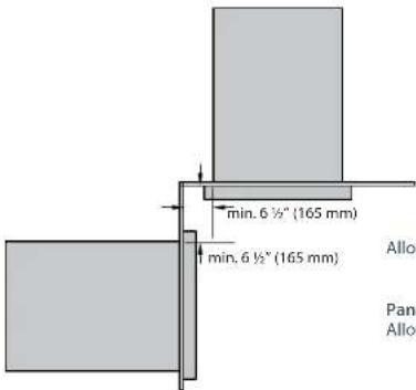
min. 6 ½" (165 mm) min. 6 ½" (165 mm) Allo Pan AlloPantry unit and drawer / waste bin
Allow min. 6 1/2" (165mm) clearance from the cutout to the corner for each product.
Pantry unit and Beverage chiller with bottle holder Allow min. 9 1/2" (241mm) clearance from the cutout to the corner for each product
text_image
measured from back of frame 1 ¾" (35 mm) 10 ¼" (260 mm) 3 ¾" (95 mm) 3 ¾" (95 mm) min. 7/16" (11 mm) min. 1 ¾/16" (30 mm) 3/8" (16 mm) Provide a support above the chassis to screw up into There is an additional "step" on the pantry chassis that must be considered when locating the supports
INSERT PRODUCT INTO CAVITY & SECURE
1 With the help of an assistant, lift the unit and slide it into the cabinet cutout along the supports. Adjust for level and fit.
2 Locate the mounting holes (front top left and right sides and front base of drawer compartment).
3 Remove the transit plugs from the holes you intend to use.
4 Secure the unit using countersunk screws suitable for the type of cabinetry materials used.
We recommend using all the shown hole locations for securing.
natural_image
Pure technical diagram of a mechanical or architectural component with no text, numbers, or symbols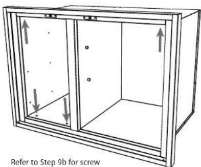
text_image
Refer to Step 9b for screwRefer to Step 9b for screw mounting hole positions

natural_image
Pure architectural or mechanical diagram showing a vertical frame with horizontal supports and a small rectangular component, no text or symbols present.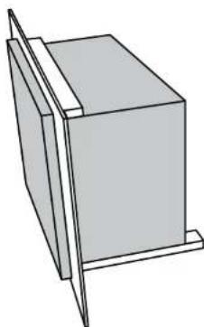
natural_image
Simple line drawing of a rectangular box with a vertical tab on top, no text or symbols present
REPLACE ALL DRAWERS & SHELVES
To replace the drawer(s)
1 Extend both guide rails out.
2 Engage the drawer rails into the guide rails. Pull the guide rails forward until they 'click' into place.
3 Push the drawer all the way in (there will be some resistance) to completely engage the drawer.
text_image
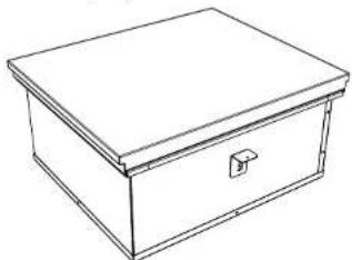
Extend guide rails Engage drawer railsINSTALLING BEVERAGE CHILLER / BOTTLE HOLDER (PURCHASED SEPERATELY)

DISCARD PACKAGING
Model may vary from illustrations shown
natural_image
Line drawing of a rectangular box with a lid and handle (no text or symbols)
Recycle responsibly
Inspect the product(s) to verify that there is no shipping damage. If any damage is detected, call the shipper and initiate a damage claim. DCS by Fisher & Paykel is not responsible for shipping damage.
NOTE: Do not discard any packing material until the unit has been inspected. Examine the product to be sure there are no dents or scratches or discoloring.

PREPARE THE CAVITY
- Ensure the base of the cavity is level, square and able to support the weight of the product when full.
- Any cabinet and/or ground preparation must be completed prior to installation.
- All support structures must be constructed of materials resistant to moisture damage.
- Do no use harsh products (acid, solvent, sealers) around this product.
- For installation with the Bottle holder (purchased separately), the cutout must extend to the front of the cabintry, allowing space for the bottle holder (as shown).
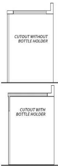
text_image
CUTOUT WITHOUT BOTTLE HOLDER CUTOUT WITH BOTTLE HOLDER
OPTIONALLY ATTACH BOTTLE HOLDER(PURCHASED SEPERATELY) TO BEVERAGE CHILLER
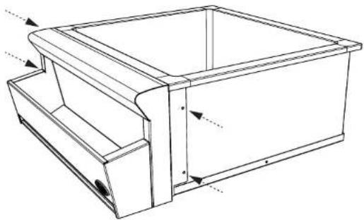
natural_image
Technical line drawing of a mechanical housing or enclosure with internal components and mounting holes (no text or symbols)1 Fit the bottle holder onto the front of the Beverage chiller.
2 Attach the bottle holder to the Beverage chiller with the screws provided.
3 Unwrap the drip tray and fit in the bottom of the bottle holder.
10c LOWER PRODUCT INTO CUTOUT, ATTACH MOUNTING BRACKETS & SECURE
1 With the help of an assistant lower the chiller into the cutout, ensuring the drain outlet is accessible.
2 Locate the mounting holes on each side of the beverage chiller and screw in the provided mounting clamps at the appropriate level for the countertop.
3 Secure the beverage chiller into place by tightening the clamping screws against the countertop on two sides.
text_image
Diagram illustrating a hand holding a warning sign and a warning triangle above a cabinet with a shield-shaped opening.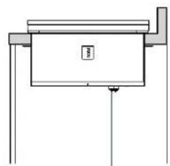
natural_image
Simple line drawing of a mechanical or architectural component with no text, numbers, or symbolsDrain outlet
Each mounting clamp comes with 4 positions. Screw the clamps into the most appropriate position using the screws provided.
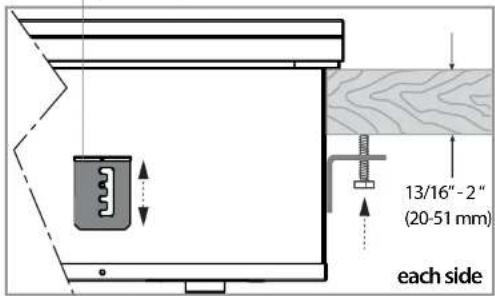
text_image
13/16"-2" (20-51 mm) each side⑪ CONNECT TO THE DRAINAGE SYSTEM
It is recommended that the Beverage Chiller be connected to the permanent waste drainage system.
Important!
Connection to the existing drainage system must be carried out by certified plumber and in accordance with local codes and regulations.
The sink drain connection is 1-1/2" NPS male thread.

FINAL CHECKLIST

TO BE COMPLETED BY THE INSTALLER
Are products secure and level within the enclosure?
Are all the drawers, doors and shelves fitted correctly and open and shut smoothly?
□ Have you demonstrated the basic operation to the customer?
Are the soft close drawers working correctly?
(Note: the pantry doors and drawers are not soft closing).
BC25 Beverage Chiller only:
□ Have you installed the clamping brackets?
□ Has all the suitable plumbing connections been checked?
Installer's name:
Instoller's signature:
Installation company:
Date of installation:
LEAVE THESE INSTRUCTIONS WITH THE CUSTOMER
Important!
SAVE THESE INSTRUCTIONS
The models shown in this document may not be available in all markets and are subject to change at any time. For current details about model and specification availability in your country, please visit our website listed at the end of this document or contact your local Fisher & Paykel dealer.
INSTRUCTIONS D'INSTALLATION
③ OUTILS REQUIS (NON FOURNIS)
④ DIMENSIONS DU PRODUIT - TIROIRS, GARDE-MANGER ET CORBEILLE À DÉCHETS
text_image
C D DESSUSnatural_image
Architectural line drawing of a two-story building structure with no text or symbolsnatural_image
Pure technical line drawing of a rectangular frame mounted on a vertical support structure (no text or symbols)natural_image
Line drawing of a three-drawer filing cabinet with drawers (no text or symbols)INSTALLATION DANS UN COIN
text_image
min. 1 ½ po (28 mm) Laissez moins l'pINSTALLATION DANS UN COIN AVEC DEUX PRODUITS
INSÉREZ LE PRODUIT DANS LA CAVITÉ ET FIXEZ-LE
natural_image
Diagram of a mechanical assembly with two components, one showing an arrow indicating direction (no text or symbols present)
natural_image
Diagram of a wooden crate with arrows indicating force or movement (no text or symbols)natural_image
Simple line drawing of a rectangular box mounted on a stand (no text or symbols)natural_image
Simple line drawing of a door with a handle and two legs, showing an arrow indicating direction (no text or symbols)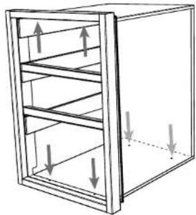
natural_image
Diagram of a 3D cabinet with horizontal shelves and vertical arrows indicating force or movement (no text or symbols)natural_image
Pure architectural or mechanical diagram showing a rectangular structure with supports and directional arrows, no text or symbols present.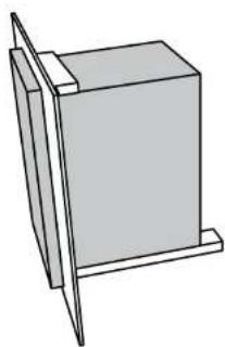
natural_image
Simple line drawing of a rectangular block mounted on a stand, no text or symbols present⑪ RÉINSÉREZ LES TIROIRS
natural_image
Simple line drawing of a rectangular box placed on a wooden platform (no text or symbols)natural_image
Technical line drawing of a mechanical cabinet or enclosure with internal components and mounting brackets (no text or symbols)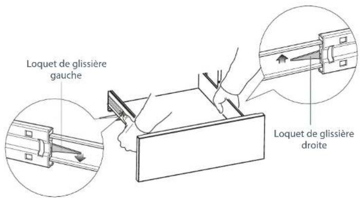
INSTALLATIONS DANS UN COIN
text_image
min. 1 ½ po (28 mm) Laisse moinINSTALLATIONS DANS UN COIN AVEC DEUX PRODUITS (INCLUANT LE GARDE-MANGER)

text_image
min. 6 ½ po (165 mm) min. 6 ½ po (165 mm)INSÉREZ LE PRODUIT DANS LA CAVITÉ ET FIXEZ-LE
natural_image
Diagram of a mechanical or architectural component with a rectangular frame and multiple horizontal supports, showing no text or symbols.
natural_image
Pure architectural or mechanical diagram showing a vertical frame with horizontal supports and a central rectangular block, no text or symbols present.
natural_image
Simple line drawing of a rectangular box with a vertical tab on top, no text or symbols present11b RÉINSÉREZ TOUS LES TIROIRS ET TOUTES LES TABLETTES
natural_image
Line drawing of a rectangular box with a lid and handle (no text or symbols)natural_image
Technical line drawing of a rectangular box with internal compartments and mounting holes (no text or symbols)text_image
Diagram illustrating a hand holding a warning sign and a warning triangle above a cabinet with a lid, indicating hazard or caution.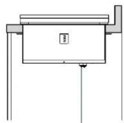
natural_image
Simple line drawing of a mechanical or architectural component with no text, numbers, or symbolsSortie de vidange