EHI613SS - Basket ELICA - Free user manual and instructions
Find the device manual for free EHI613SS ELICA in PDF.

User questions about EHI613SS ELICA
0 question about this device. Answer the ones you know or ask your own.
Ask a new question about this device
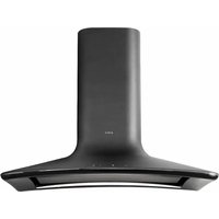
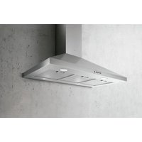
Download the instructions for your Basket in PDF format for free! Find your manual EHI613SS - ELICA and take your electronic device back in hand. On this page are published all the documents necessary for the use of your device. EHI613SS by ELICA.
USER MANUAL EHI613SS ELICA
READ AND SAVE THESE INSTRUCTIONS LISEZ CES INSTRUCTIONS ET CONSERVEZ-LES LEA Y GUARDE ESTAS INSTRUCCIONES
READ AND SAVE THESE INSTRUCTIONS LISEZ CES INSTRUCTIONS ET CONSERVEZ-LES LEA Y GUARDE ESTAS INSTRUCCIONES
EHI648WH - EHI648BL - EHI648SS EHI613SS - EHI670SS
READ AND SAVE THESE INSTRUCTIONS
APPROVED FOR RESIDENTIAL APPLIANCES FOR RESIDENTIAL USE ONLY READ AND SAVE THESE INSTRUCTIONS
PLEASE READ ENTIRE INSTRUCTIONS BEFORE PROCEEDING.
INSTALLATION MUST COMPLY WITH ALL LOCAL CODES.
IMPORTANT: Save these Instructions for the Local Electrical Inspector's use.
INSTALLER: Please leave these Instructions with this unit for the owner.
OWNER: Please retain these instructions for future reference.
Safety Warning: Turn off power circuit at service panel and lock out panel, before wiring this appliance.
Requirement: 120V, 60 Hz, 15 or 20 A Branch Circuit
Removing the packaging
CAUTION!
Remove carton carefully, Wear gloves to protect against sharp edges.
WARNING!
Remove the protective film covering the product before putting into operation.

text_image
NOM- PRODUCTO CERTIFICADO ANCE CERTIFIED PRODUCTRange Hood EHI648WH, EHI648BL, EHI648SS, EHI613SS, EHI670SS
Rated Voltage: 120 V\~
Frequency: 60 Hz
Power consumption: 460 W
Current consumption:3,8 A
Number: 1 piece.
Made in Italy
Manufactured by: Elica SPA
Imported by : ELICAMEX S.A. de C.V.
Address: Av. La Noria No. 102 int. S/N, Col. Parque
Industrial Querétaro
Del. Santiago de Querétaro, C.P. 76220 Querétaro,
R.F.C. EII060102RK8
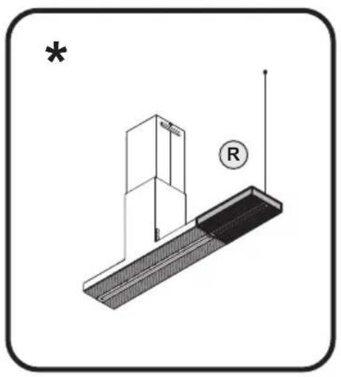
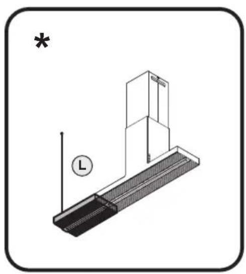
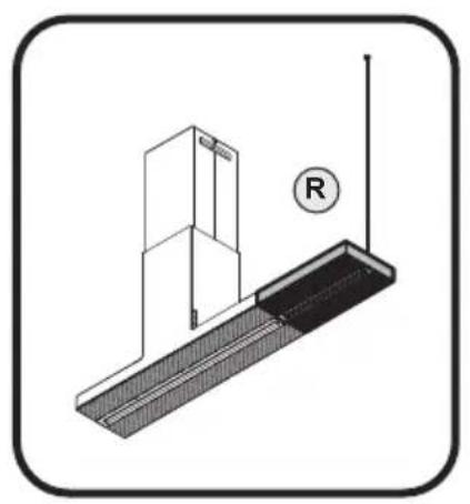
Note: The parts marked with the symbol "(*)" are optional accessories supplied only with some models or otherwise not supplied, but available for purchase.

Important safety Notice
CAUTION
FOR GENERAL VENTILATING USE ONLY. DO NOT USE TO EXHAUST HAZARDOUS OR EXPLOSIVE MATERIALS OR VAPOURS.
WARNING
TO REDUCE THE RISK OF FIRE, ELECTRIC SHOCK, OR INJURY TO PERSONS, OBSERVE THE FOLLOWING:
A. Use this unit only in the manner intended by the manufacturer. If you have questions, contact the manufacturer.
B. Before servicing or cleaning the unit, switch power off at service panel and lock service panel disconnecting means to prevent power from being switched on accidentally. When the service disconnecting means cannot be locked, securely fasten a prominent warning device, such as a tag, to the service panel.
WARNING
TO REDUCE THE RISK OF FIRE, ELECTRIC SHOCK, OR INJURY TO PERSONS, OBSERVE THE FOLLOWING:
A. Installation Work and Electrical Wiring Must Be Done By Qualified Person(s) In Accordance With All Applicable Codes & Standards, Including Fire-rated Construction.
B. Sufficient air is needed for proper combustion and exhausting of gases through the flue (Chimney) of fuel burning equipment to prevent back- drafting. Follow the heating equipment manufacturers guideline and safety standards such as those published by the National Fire Protection Association (NFPA), the American Society for Heating, Refrigeration and Air Conditioning Engineers (ASHRAE), and the local code authorities.
C. When cutting or drilling into wall or ceiling, do not damage electrical wiring and other hidden utilities.
D. Ducted systems must always be vented to the outdoors.
CAUTION
To reduce risk of fire and to properly exhaust air, be sure to duct air outside - do not vent exhaust air into spaces within walls, ceilings, attics, crawl spaces, or garages.
WARNING
TO REDUCE THE RISK OF FIRE, USE ONLY METAL DUCT WORK.
Install this hood in accordance with all requirements specified.
WARNING
To Reduce The Risk Of Fire Or Electric Shock, Do Not Use This Hood With Any External Solid State Speed Control Device.
WARNING
TO REDUCE THE RISK OF A RANGE TOP GREASE FIRE.
a) Never leave surface units unattended at high settings. Boilovers cause smoking and greasy spillovers that may ignite. Heat oils slowly on low or medium settings.
b) Always turn hood ON when cooking at high heat or when flambeing food (i.e. Crepes Suzette, Cherries Jubilee, Peppercorn Beef Flambe').
c) Clean ventilating fans frequently. Grease should not be allowed to accumulate on fan or filter.
d) Use proper pan size. Always use cookware appropriate for the size of the surface element.
WARNING
TO REDUCE THE RISK OF INJURY TO PERSONS, IN THE EVENT OF A RANGE TOP GREASE FIRE, OBSERVE THE FOLLOWING ^a :
a) SMOTHER FLAMES with a close-fitting lid, cookie sheet, or other metal tray, then turn off the gas burner or the electric element. BE CAREFUL TO PREVENT BURNS. If the flames do not go out immediately, EVACUATE AND CALL THE FIRE DEPARTMENT.
b) NEVER PICK UP A FLAMING PAN - you may be burned.
c) DO NOT USE WATER, including wet dishcloths or towels - a violent steam explosion will result.
d) Use an extinguisher ONLY if:
1) You know you have a class ABC extinguisher,
and you already know how to operate it.
2) The fire is small and contained in the area where it started.
3) The fire department is being called.
4) You can fight the fire with your back to an exit.
^a Based on "Kitchen Firesafety Tips" published by NFPA.
OPERATION
a. Always leave safety grills and filters in place. Without these components, operating blowers could catch onto hair, fingers and loose clothing.
The manufacturer declines all responsibility in the event of failure to observe the instructions given here for installation, maintenance and suitable use of the product. The manufacturer further declines all responsibility for injury due to negligence and the warranty of the unit automatically expires due to improper maintenance.
- This device is not intended for use by persons (including children) whose physical, sensory or mental abilities are different or reduced, or who lack experience or knowledge unless such persons receive supervision or training for the operation of the device by a person responsible for your safety.
- Children should be supervised to ensure they do not use the devices as a toy.
- Do not flame food under the kitchen hood.
- There must be adequate ventilation in the room, when the range hood is used at the same time as appliances that consume gas or other fuels. (DOES NOT APPLY FOR RANGEHOODS THAT ARE ONLY RECYCLING MODE).
- There is a risk of fire, if the cleaning is not carried out in accordance with the instructions.
- The discharge air must not be sent through a duct that is used to evacuate fumes from appliances that consume gas or other fuels. (DOES NOT APPLY FOR RANGEHOODS THAT ARE ONLY RECYCLING MODE).
- Must be complied with regulations relate to the evaluation of the air discharge.
- In the event that your power cord is damaged in part or in full, do not try to repair it by contacting the service center marked on your warranty or by a specialist technician for replacement.
Electrical & Installation requirements
Electrical requirements
IMPORTANT
Observe all local codes and ordinances.
It is the customer's responsibility:
To contact a qualified electrical installer.
To assure that the electrical installation is adequate and in conformance with National Electrical Code, ANSI/NFPA 70 — latest edition*, or CSA Standards C22.1-94, Canadian Electrical Code, Part 1 and C22.2 No.0-M91 - latest edition** and all local codes and ordinances.
If codes permit and a separate ground wire is used, it is recommended that a qualified electrician determine that the ground path is adequate.
GROUNDING INSTRUCTIONS
This appliance must be grounded. In the event of an electrical short circuit, grounding reduces the risk of electric shock by providing an escape wire for the electric current. This appliance is equipped with a cord having a grounding wire with a grounding plug. The plug must be plugged into an outlet that is properly installed and grounded.
WARNING – Improper grounding can result in a risck of electric shock.
Consult a qualified electrician if the grounding instructions are not completely understood, or if doubt exists as to whether the appliance is properly grounded.
Do not use an extension cord. If the power supply cord is too short, have a qualified electrician install an outlet near the appliance.
Do not ground to a gas pipe.
Check with a qualified electrician if you are not sure range hood is properly grounded.
Do not have a fuse in the neutral or ground circuit.
Do not operate any fan with a damaged cord or plug. Discard fan or return to an authorized service facility for examination and/or repair.
Do not run cord under carpeting.
Do not cover cord with throw rugs, runners, or similar coverings. Do not route cord under furniture or appliances. Arrange cord away from traffic area and where it will not be tripped over.
IMPORTANT
Save Installation Instructions for electrical inspector's use.
The range hood should be connected directly to the fused disconnect (Or circuit breaker).
Wire sizes must conform to the requirements of the National Electrical Code ANSI/NFPA 70 — latest edition*, or CSA Standards C22.1-94, Canadian Electrical Code Part 1 and C22.2 No. 0-M91 - latest edition** and all local codes and ordinances.
Copies of the standards listed may be obtained from:
* National Fire Protection Association Batterymarch Park Quincy, Massachusetts 02269
** CSA International 8501 East Pleasant Valley Road Cleveland, Ohio 44131-5575
Before installing the hood
- For the most efficient air flow exhaust, use a straight run or as few elbows as possible.
CAUTION: Vent unit to outside of building, only.
-
At least two people are necessary for installation. Wear gloves to protect against sharp edges.
-
Fittings material is provided to secure the hood to most types of walls/ceilings, consult a Qualified Installer, check if they perfectly fit with your cabinet/wall.
-
Do not use flex ducting.
-
COLD WEATHER installations should have an additional backdraft damper installed to minimize backward cold air flow and a nonmetallic thermal break to minimize conduction of outside temperatures as part of the ductwork. The damper should be on the cold air side of the thermal break.
The break should be as close as possible to where the ducting enters the heated portion of the house.
- Make up air: Local building codes may require the use of Make-Up Air Systems when using Ducted Ventilation Systems greater than specified CFM of air movement.
The specified CFM varies from locale to locale. Consult your HVAC professional for specific requirements in your area.
All fastener location must span the studs otherwise proceed as follows:
Cutout drywall along marked lines. Install wood blocking between studs and make sure it is flush with existing stud front. Make sure all mounting screws will anchor to added studs. Replace drywall and refinish.
When used in recirculation mode, To Reduce the Risk of Fire and Shock use only conversion kit Model: KIT Long Life.
Use
The hood is designed to be used either for exhausting or filter version.

Extraction version
In this case the fumes are conveyed outside of the building by means of a special pipe connected with the connection ring located on top of the hood.

CAUTION!
The exhausting pipe is not supplied and must be purchased apart.
Diameter of the exhausting pipe must be equal to that of the connection ring.

CAUTION!
If the hood is supplied with active charcoal filter, then it must be removed.
Connect the hood and discharge holes on the walls with a diameter equivalent to the air outlet (connection flange).
Using the tubes and discharge holes on walls with smaller dimensions will cause a diminution of the suction performance and a drastic increase in noise.
Any responsibility in the matter is therefore declined.
! Use a duct of the minimum indispensable length.
! Use a duct with as few elbows as possible (maximum elbow angle: 90°).
! Avoid drastic changes in the duct cross-section.

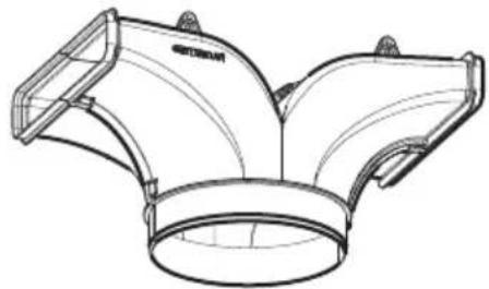
Filtration version
The aspirated air will be degreased and deodorised before being fed back into the room.
In order to use the hood in this version, you have to install a system of additional filtering based on activated charcoal.
Installation
Specialised personnel must carry out both the electrical and the mechanical installation.
Do not cut a joist or stud unless absolutely necessary. If a joist or stud must be cut, then a supporting frame must be constructed.
Fittings material is provided to secure the hood to most types of walls/ceilings.
However, a qualified technician must verify suitability of the materials in accordance with the type of wall/ceiling.
Before making cutouts, make sure there is proper clearance within the ceiling or wall for exhaust vent.
Hood installation height above cooktop is the users preference. The lower the hood is above the cooktop, the more efficient the capturing of cooking odors, grease and smoke.
CAUTION: FOR GAS RANGES INSTALLATION: MOUNT THIS HOOD SO THAT THE BOTTOM EDGE IS AT 30" (76,2 CM) ABOVE THE COOKING SURFACE.
FOR ELECTRIC RANGES INSTALLATION: MOUNT THIS HOOD SO THAT THE BOTTOM EDGE IS NOT LESS THAN 30" (76,2 CM) ABOVE THE COOKING SURFACE. HOUSEHOLD USE. PLEASE, READ INSTALLATION MANUAL FOR SPECIFIC APPLICATION.
If the instructions for installation for the gas hob specify a greater distance, this must be adhered to.
Check your ceiling height and the hood height maximum before you select your hood.
Consult last pages of this manual for installation instruction and electrical connection steps.
Operation
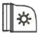
ON/OFF light button
Press to turn the cooktop light on or off.
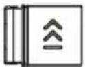
"BOOST" speed selection key
1st push: to activate the intensive suction speed "BOOST", timed for 7 minutes
Note: after 7 minutes, the hood will return to the previously set suction speed
2nd push ("BOOST" activated): to exit the function and return to the speed previously set.
Note: the speed key previously set remains lit during BOOST operation.
Speed selection key 3
Push to activate the high speed (suction power)
Speed selection key 2
Push to activate the average speed (suction power)
Speed selection key 1
Push to enable the low speed (suction power)
Power button
Push to switch on the hood and enable speed selection;
if pushed while the motor is running, the latter will stop
Note: if no function is activated within 10 seconds, the hood turns off.
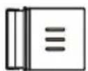
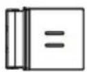
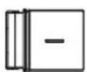
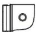
Filter Saturation indicator lights
The hood signals at regular intervals that the filters must be serviced.
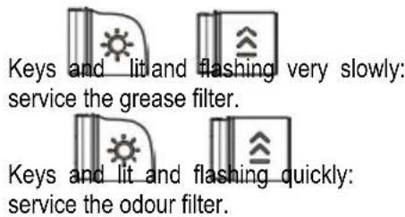
text_image
Keys and lit and flashing very slowly: service the grease filter. Keys and lit and flashing quickly: service the odour filter.Note: The filter saturation warning signal is visible within the first 10 seconds after the hood is switched on.
Reset filter saturation indicator:
Press and hold the keys and The keys will flash quickly to confirm that reset has been completed
Activation of filter saturation indicators
Note: this operation must be performed with the hood off.
- Grease filter
Push and hold down the keys activate the function


the keys light up flashing very slowly, indicating that the grease filter indicator can be activated
Note: Push the keys and to activate or deactivate
- Odour filter
Push and hold down the keys activate the function


the keys light up flashing quickly, indicating that the odour filter indicator can be activated (normally deactivated)
Note: Push the keys and to activate or deactivate
User Servicing and Maintenance Instructions
Cleaning
Clean using ONLY a cloth dampened with neutral liquid detergent. DO NOT CLEAN WITH TOOLS OR INSTRUMENTS. Do not use abrasive products. DO NOT USE ALCOHOL!
Grease filter
Fig. 38 / 48-52
Traps cooking grease particles.
This must be cleaned once a month (or when the filter saturation indication system – if envisaged on the model in possession – indicates this necessity) using non aggressive detergents, either by hand or in the dishwasher, which must be set to a low temperature and a short cycle.
When washed in a dishwasher, the grease filter may discolor slightly, but this does not affect its filtering capacity.
To remove the grease filter, pull the spring release handle.
Charcoal filter (filter version only)
Fig. 51
It absorbs unpleasant odors caused by cooking.
The charcoal filter can be washed once every two months (or when the filter saturation indication system – if envisaged on the model in possession – indicates this necessity) using hot water and a suitable detergent, or in a dishwasher at 65^ C (if the dishwasher is used, select the full cycle function and leave dishes out).
Eliminate excess water without damaging the filter, then put it in the oven for 10 minutes at 100^ C to dry completely. Replace the mattress every 3 years and when the cloth is damaged.
Replacing lamps
1x7 W LED
The hood is equipped with a lighting system based on LED technology.
The LEDs guarantee an optimum lighting, a duration up to 10 times longer than the traditional lamps and allow to save 90% electrical energy.
For replacement, contact the technical service.
ELICA North America TWO-YEARS LIMITED WARRANTY
TO OBTAIN SERVICE UNDER WARRANTY
Owner must present proof of original purchase date. Please keep a copy of your dated proof of purchase (sales slip) in order to obtain service under warranty.
PARTS AND SERVICE WARRANTY
For the period of two (2) years from the date of the original purchase, Elica will provide free of charge, non consumable parts or components that failed due to manufacturing defects. During these two (2) years limited warranty, Elica will also provide free of charge, all labor and in-home service to replace any defective parts.
WHAT IS NOT COVERED
- Damage or failure to the product caused by accident or act of God, such as, flood, fire or earthquake.
- Damage or failure caused by modification of the product or use of non-genuine parts.
- Damage or failure to the product caused during delivery, handling or installation.
- Damage or failure to the product caused by operator abuse.
- Damage or failure to the product caused by dwelling fuse replacement or resetting of circuit breakers.
- Damage or failure caused by use of product in a commercial application.
• Service trips to dwelling to provide use or installation guidance. - Light bulbs, metal or carbon filters and any other consumable part.
• Normal wear of finish. - Wear to finish due to operator abuse, improper maintenance, use of corrosive or abrasive cleaning products/pads and oven cleaner products.
WHO IS COVERED
This warranty is extended to the original purchaser for products purchased for ordinary residential use in North America (Including the United States, Guam, Puerto Rico, US Virgin Islands & Canada). This warranty is non-transferable and applies only to the original purchaser and does not extend to subsequent owners of the product. This warranty is made expressly in lieu of all other warranties, expressed or implied, including, but not limited to any implied warranty of merchantability or fitness for a particular purpose and all other obligations on the part of Elica North America, provided, however, that if the disclaimer of implied warranties is ineffective under applicable law, the duration of any implied warranty arising by operation of law shall be limited to two (2) years from the date of original purchase at retail or such longer period as may be required by applicable law.
This warranty does not cover any special, incidental and/or consequential damages, nor loss of profits, suffered by the original purchaser, its customers and/or the users of the Products.
WHO TO CONTACT
To obtain service under Warranty or for any Service Related Question:
• Elica North America Authorized Service - (714) 428-0046
• elica@servicepower.com
LISEZ CES INSTRUCTIONS ET CONSERVEZ-LES
APPROUVÉ POUR LES APPAREILS DE TYPE RÉSIDENTIEL
POUR UNE UTILISATION RÉSIDENTIELLE SEULEMENT
LISEZ CES INSTRUCTIONS ET CONSERVEZ-LES
VEUILLEZ LIRE CES INSTRUCTIONS AU COMPLET AVANT DE COMMENCER.
L'INSTALLATION DE L'APPAREIL DOIT RESPECTER TOUS LES CODES EN VIGUEUR.
text_image
NOM - PRODUCTO CERTIFICADO ANCE CERTIFIED PRODUCTHotte de cuisinière EHI648WH, EHI648BL, EHI648SS, EHI613SS, EHI670SS
* La National Fire Protection Association, Batterymarch Park Quincy, Massachusetts, 02269
** La CSA International, 8501 East Pleasant Valley Road, Cleveland, Ohio, 44131-5575
• Elica North America Authorized Service - (714) 428-0046
• elica@servicepower.com
LEA Y GUARDE ESTAS INSTRUCCIONES
APROBADO PARA APARATOS DE USO
DOMÉSTICO
SÓLO PARA USO DOMÉSTICO
LEA Y GUARDE ESTAS INSTRUCCIONES
* National Fire Protection Association Batterymarch Park Quincy, Massachusetts 02269
** CSA International 8501 East Pleasant Valley Road Cleveland, Ohio 44131-5575
Antes de instalar la campana
natural_image
Technical line drawings of two mechanical or electrical components with no visible text or symbols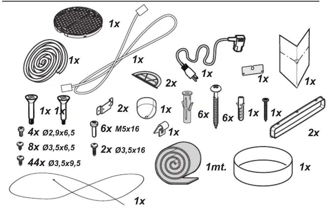
text_image
Warning symbols and hand gesture illustration showing warning, person, and handshake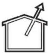

natural_image
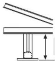
Pure mechanical diagram showing a piston-cylinder assembly with no text or symbols1
natural_image
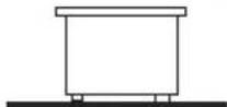
Pure mechanical diagram showing a piston-cylinder assembly with directional arrows indicating force or motion (no text or symbols)2
text_image
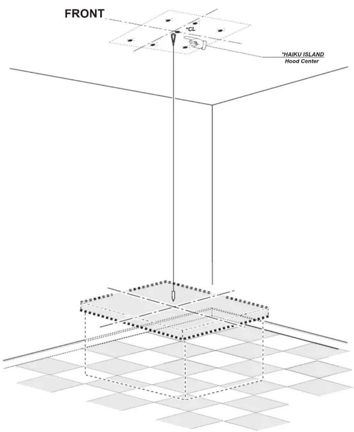
FRONT *CL *HAIKU ISLAND Hood Center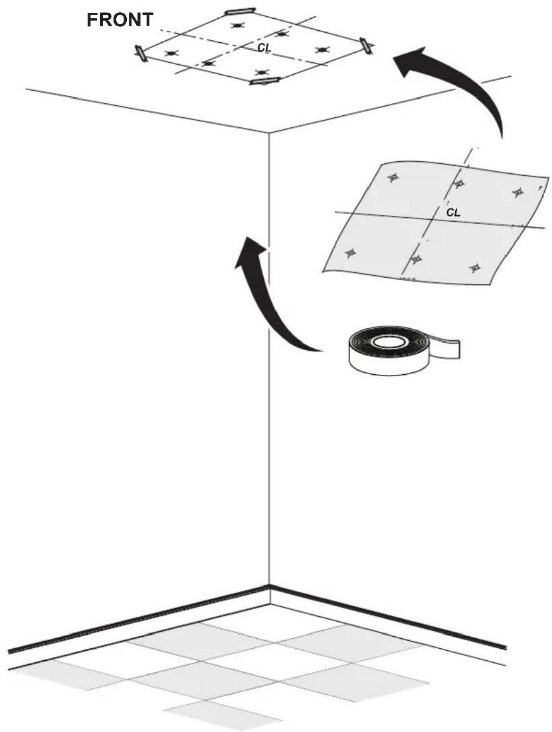
text_image
FRONT CL CL5
text_image
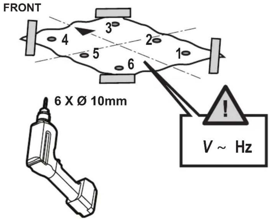
FRONT 4 3 2 1 5 6 6 X Ø 10mm V ~ HzFRONT
4 x ∅4 x 70mm

6 x ∅ 10mm
6
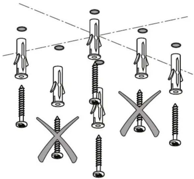
natural_image
Diagram showing various screw types and cross-shaped features, no text or symbols present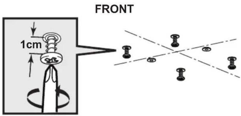
text_image
FRONT 1cm7
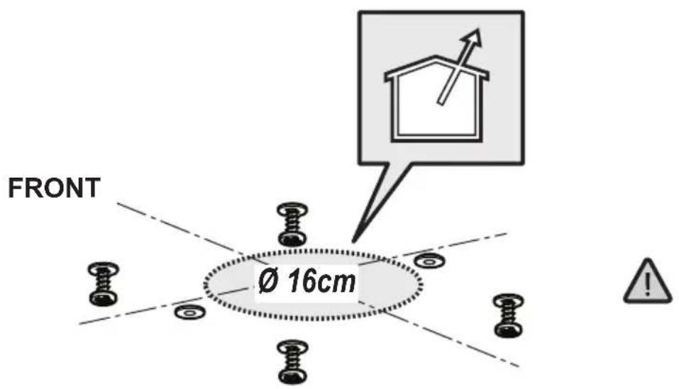
text_image
FRONT Ø 16cm8
natural_image
Icon depicting a pencil writing on a document with a calculator and page number 123 (no text or symbols present)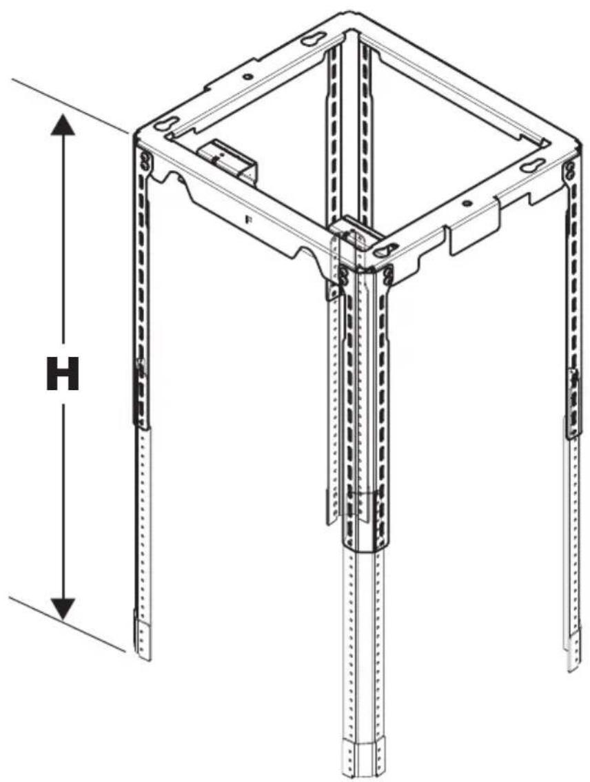
natural_image
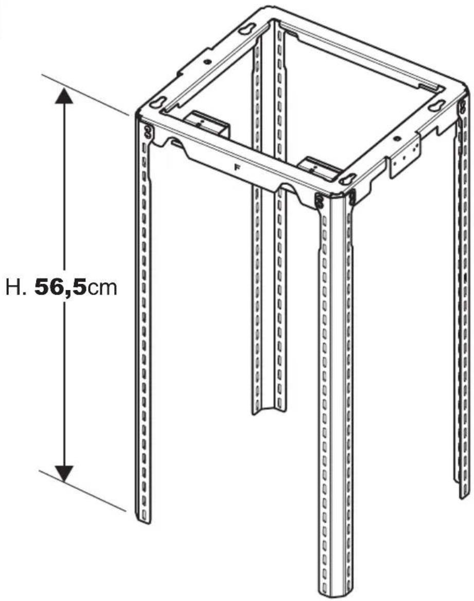
Technical line drawing of a mechanical frame structure with vertical supports and a dimension label H (no text or symbols beyond measurement indicators)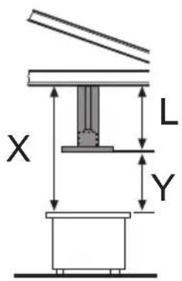
text_image
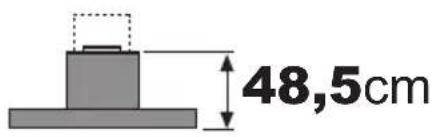
X L Y$$ \mathbf {H} _ {\mathrm{(cm)}} = (\mathbf {X} - \mathbf {Y} - 4 8, 5 \mathrm{cm}) $$
text_image
48,5cm
text_image
1.
text_image
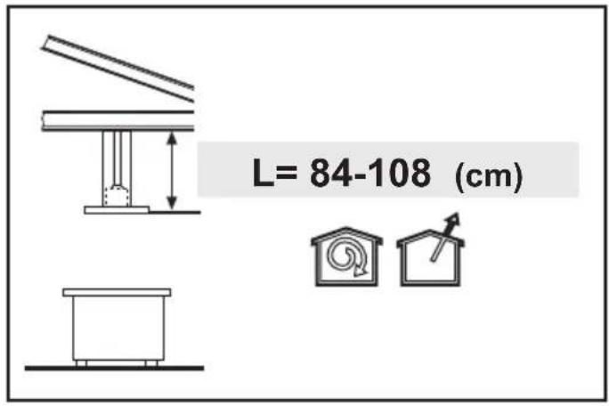
L= 84-108 (cm)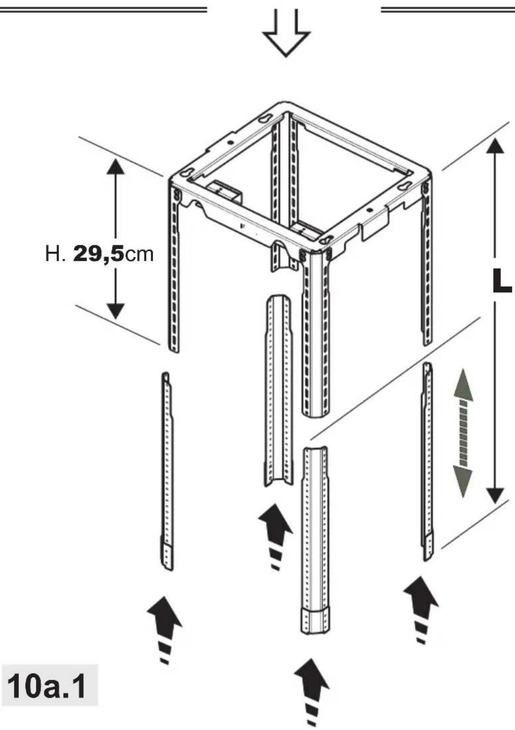
text_image
H. 29,5cm 10a.1
text_image
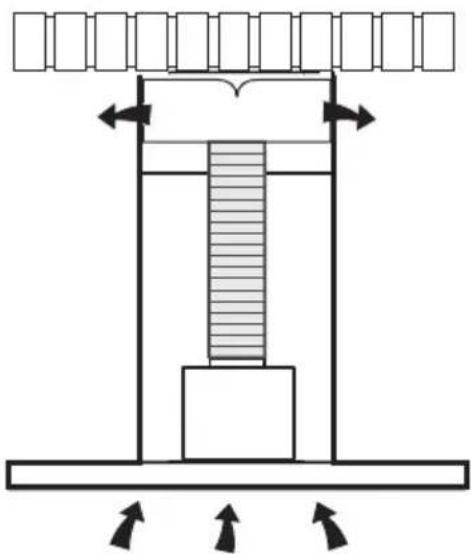
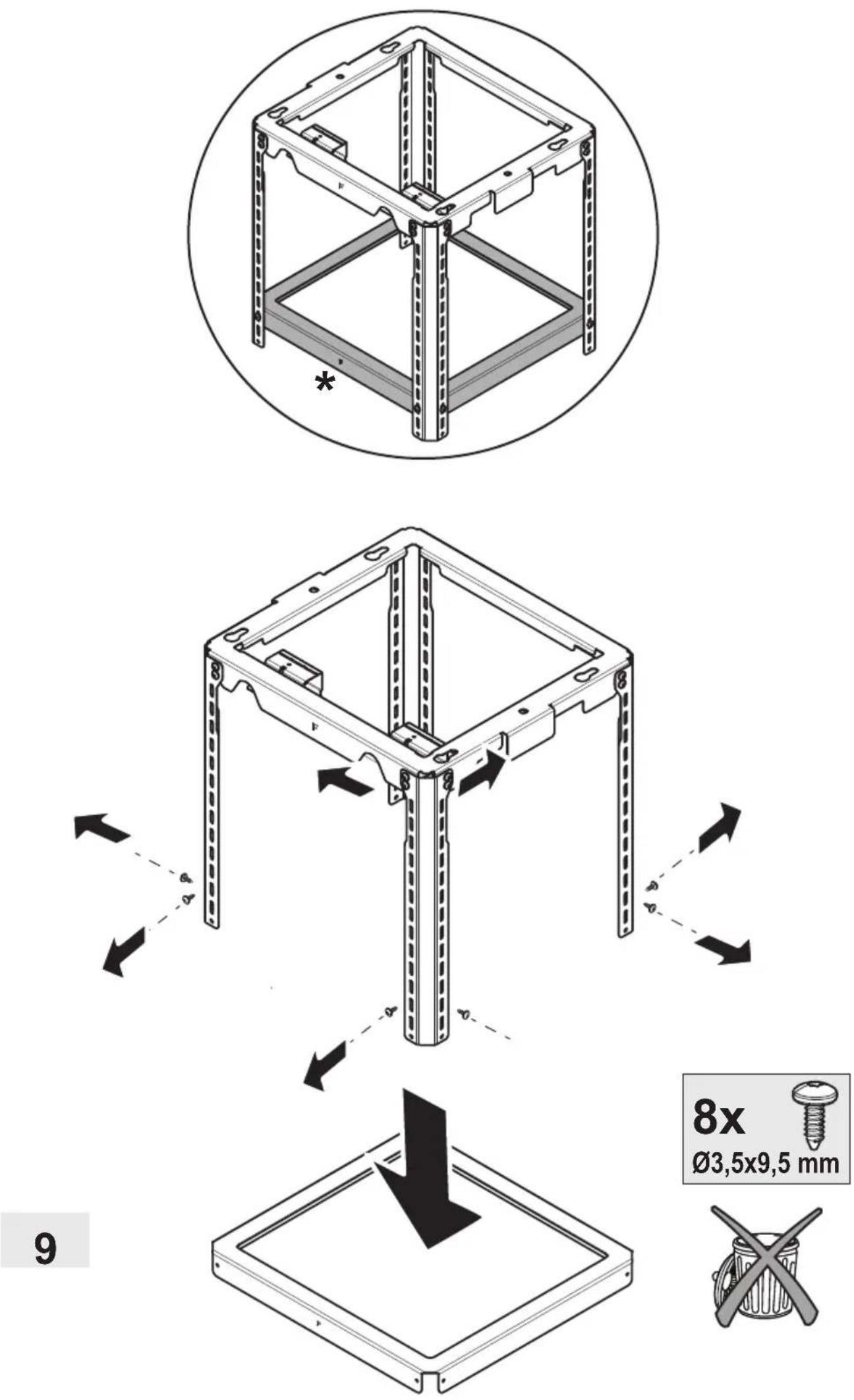
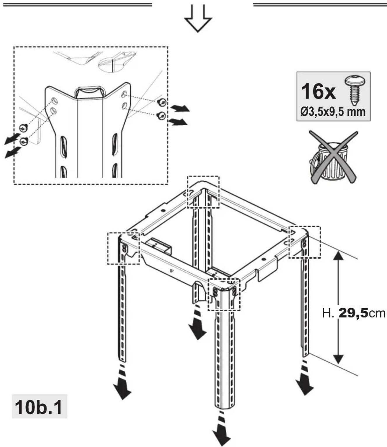
Technical diagram showing mechanical assembly with labeled components and directional arrows indicating movement or force.16x
∅3,5x9,5 mm
natural_image
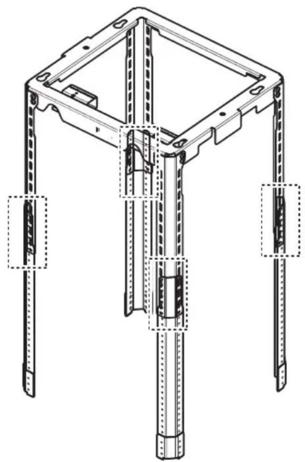
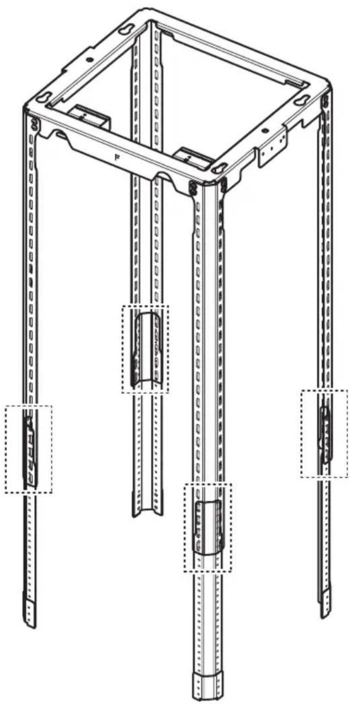
Technical line drawing of a mechanical frame structure with mounting holes and structural supports (no text or symbols)
text_image
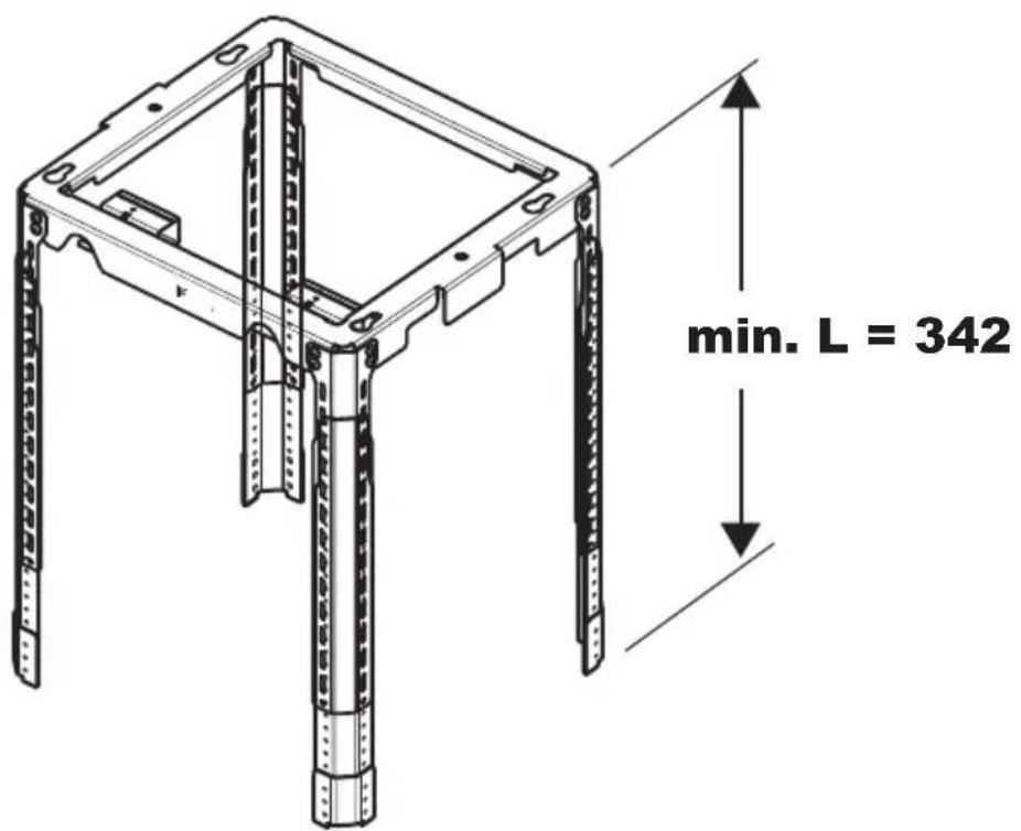
min. L = 34210a.2

natural_image
Simple line drawing of a structural support frame with diagonal beams and vertical supports (no text or symbols)L= 110-117 (cm)
L= 110-125 (cm)


text_image
16x Ø3,5x9,5 mm H. 29,5cm 10b.1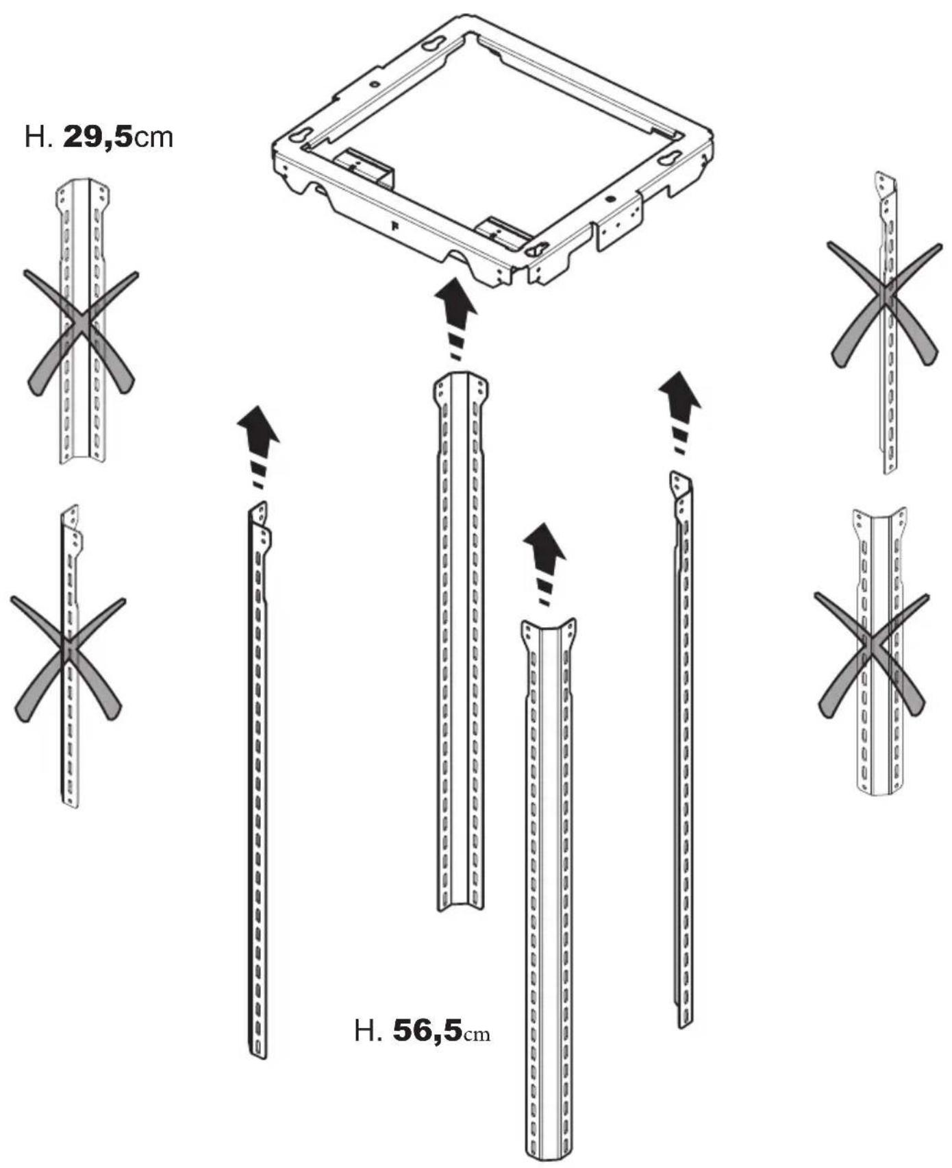
natural_image
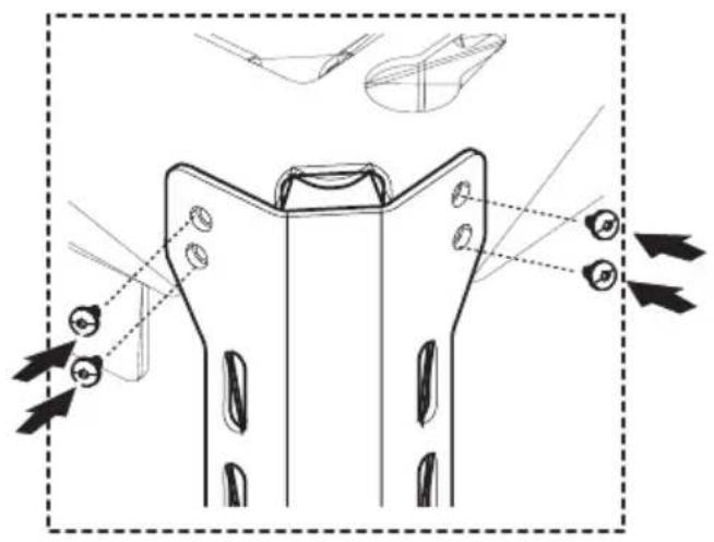
Technical line drawing of a mechanical component with mounting holes and directional arrows indicating assembly (no text or symbols)16x
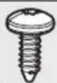
∅3,5x9,5 mm
text_image
H. 56,5cm10b.3
text_image
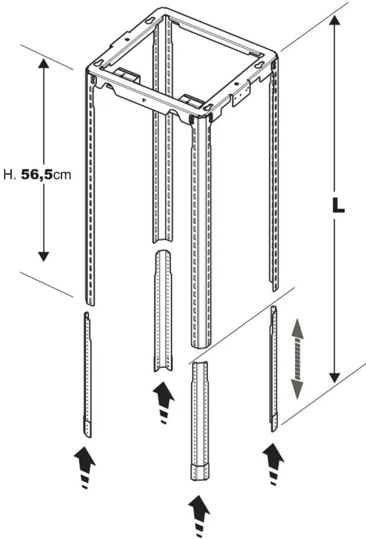
H. 56,5cm L10b.4
text_image
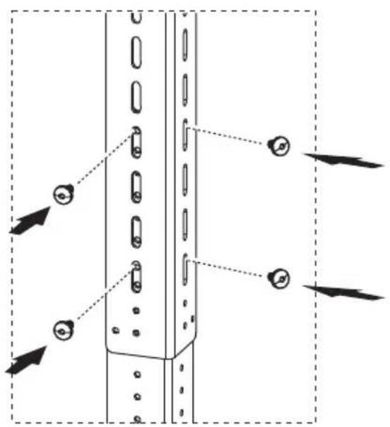
Technical diagram showing a vertical panel with multiple bolted components and directional arrows indicating movement or assembly.16x
∅3,5x9,5 mm
natural_image
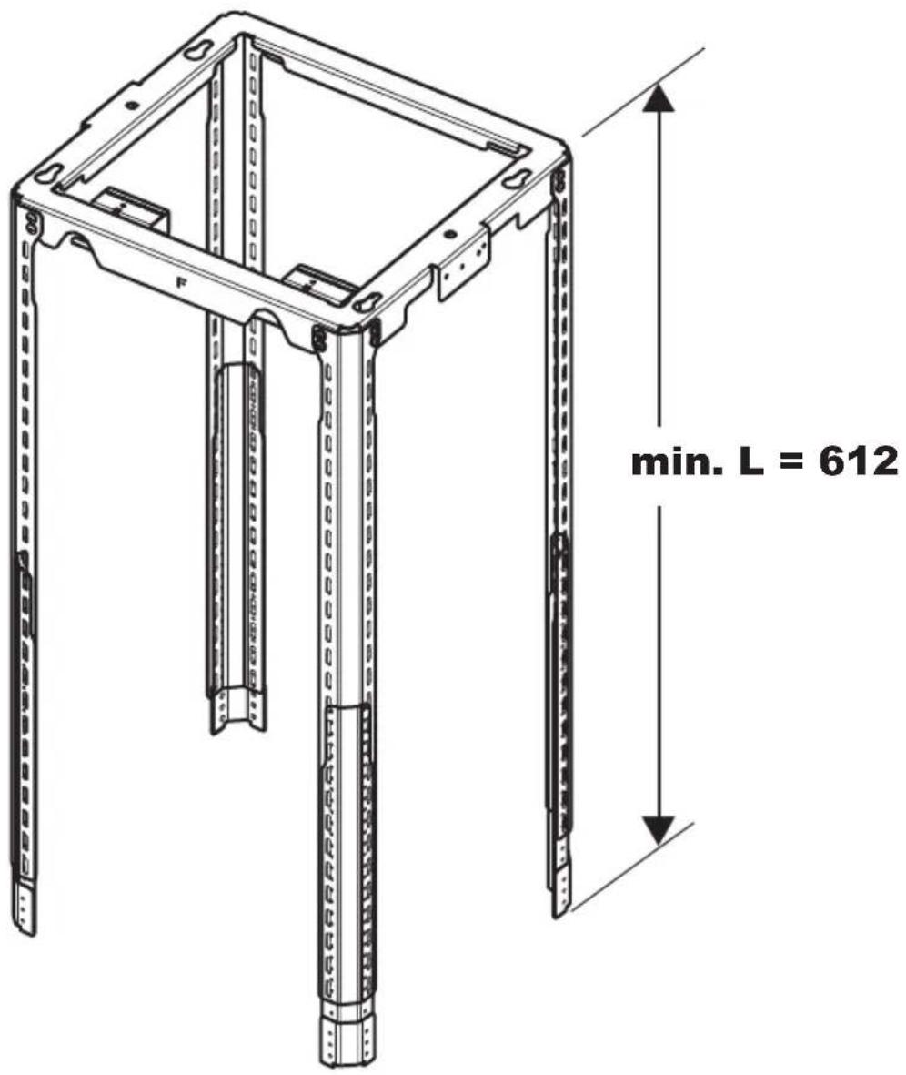
Technical line drawing of a mechanical frame structure with mounting holes and internal components (no text or symbols)10b.5

text_image
min. L = 612
natural_image
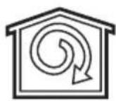
Simple line drawing of a house with a circular arrow inside, symbolizing refresh or cycle (no text or symbols)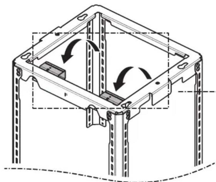
natural_image
Technical line drawing of a mechanical frame assembly with circular motion arrows indicating rotation (no text or symbols)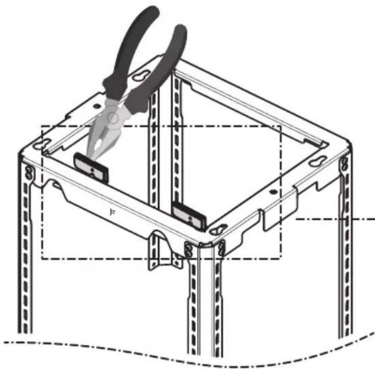
natural_image
Technical line drawing of a mechanical assembly with pliers and structural supports (no text or symbols)2x
natural_image
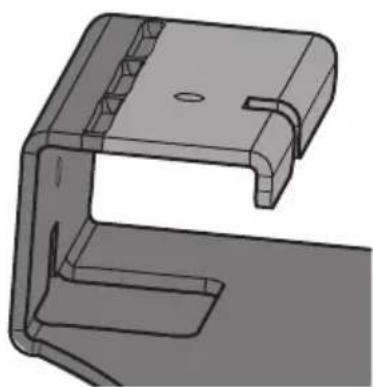
3D technical drawing of a mechanical bracket component (no text or symbols)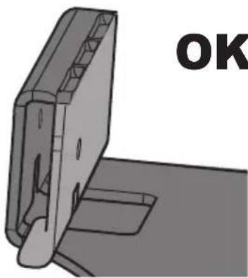
natural_image
3D mechanical part with mounting holes and a labeled 'OK' (no other text or symbols)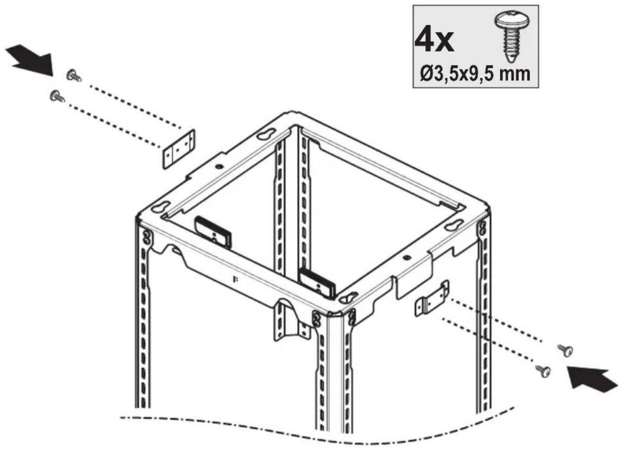
text_image
4x Ø3,5x9,5 mm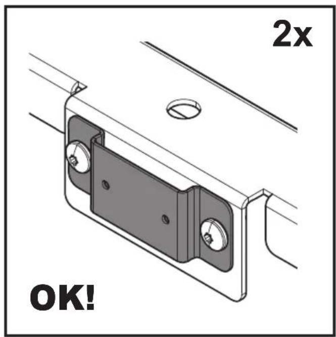
text_image
2x OK!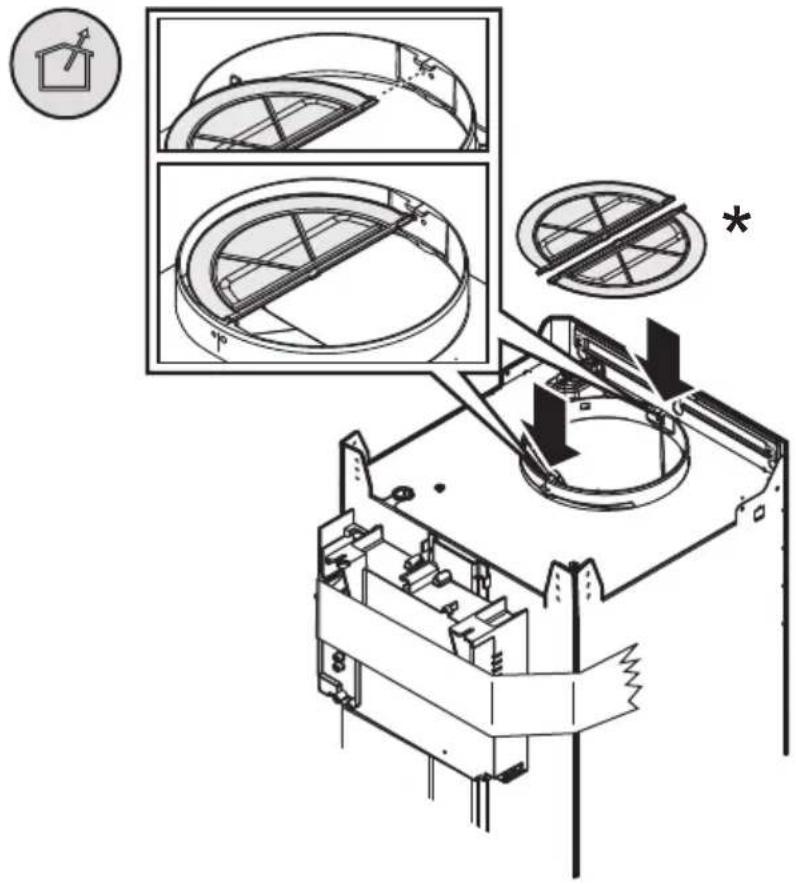
text_image
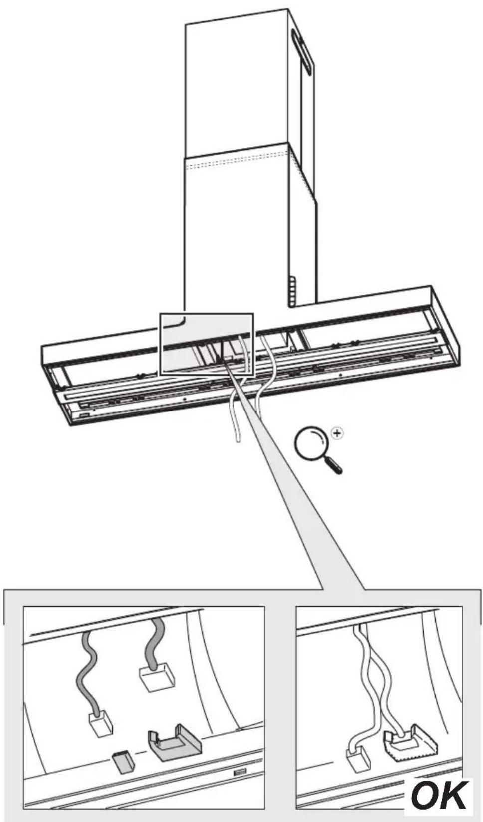
Technical diagram illustrating mechanical assembly with labeled components and directional arrows, including a magnified inset showing cross-sectional views.13
natural_image
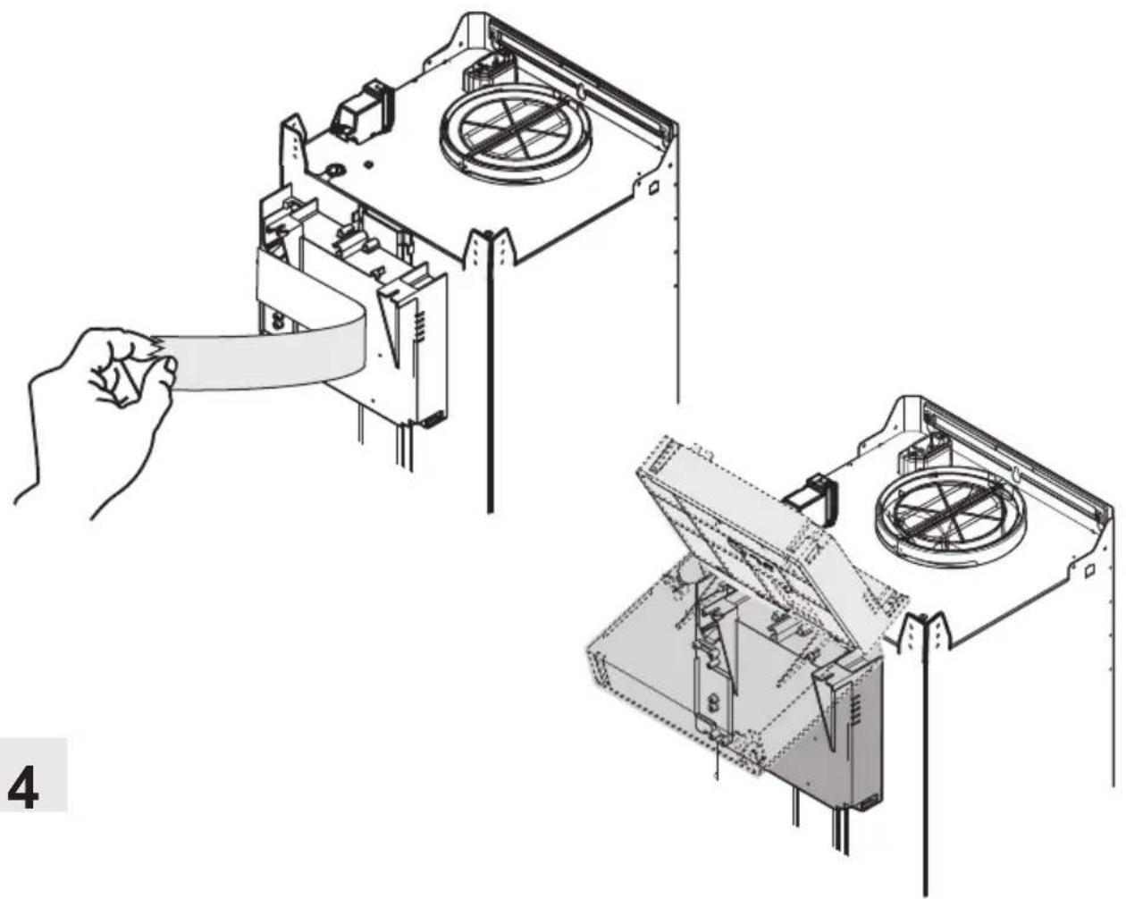
Technical illustration of a computer case with a hand holding a cable, showing internal components and assembly (no text or symbols)14
text_image
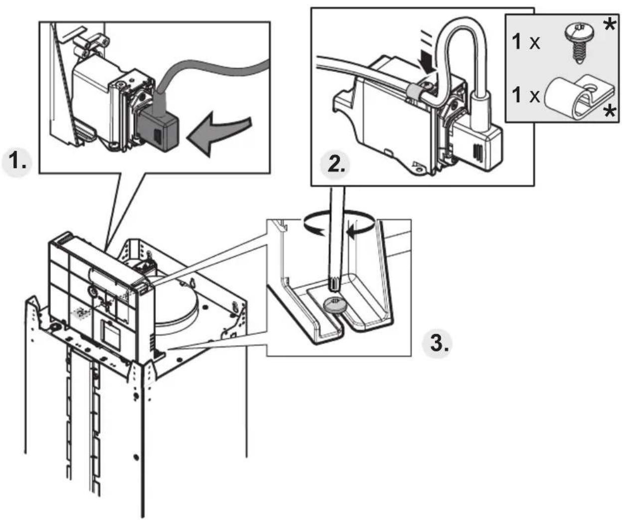
Technical diagram showing three-step assembly steps of a mechanical device with labeled components and directional arrows.
natural_image
Simple line drawing of a house with an upward arrow and a diagonal line, no text or symbols present.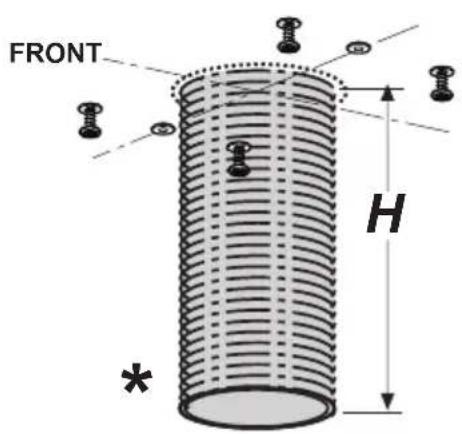
text_image
FRONT H *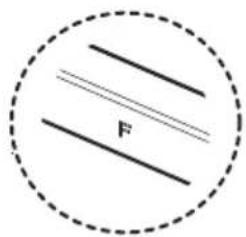
text_image
F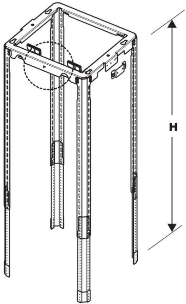
natural_image
Technical line drawing of a mechanical frame structure with dimension labels H and F (no text or symbols beyond measurement indicators)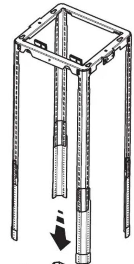
natural_image
Technical line drawing of a mechanical frame structure with mounting holes and a downward arrow indicating assembly (no text or symbols)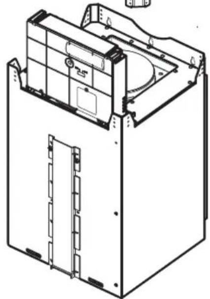
natural_image
Technical line drawing of a mechanical or electronic device casing with internal components and mounting brackets (no text or symbols)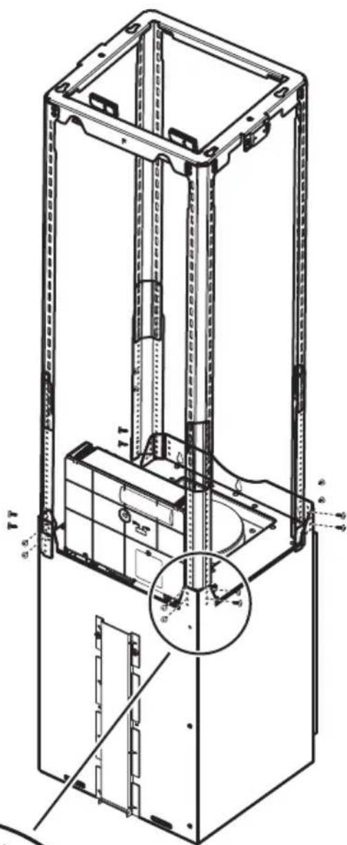
text_image
Technical diagram of a vertical shelf or elevator system with labeled components and structural details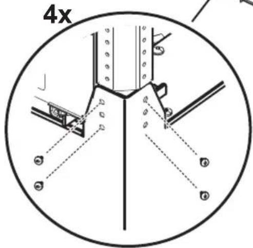
text_image
4x
text_image
16x Ø3,5x9,5 mm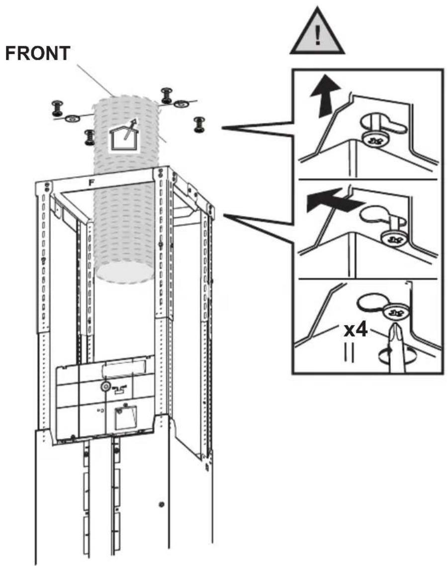
text_image
FRONT F x4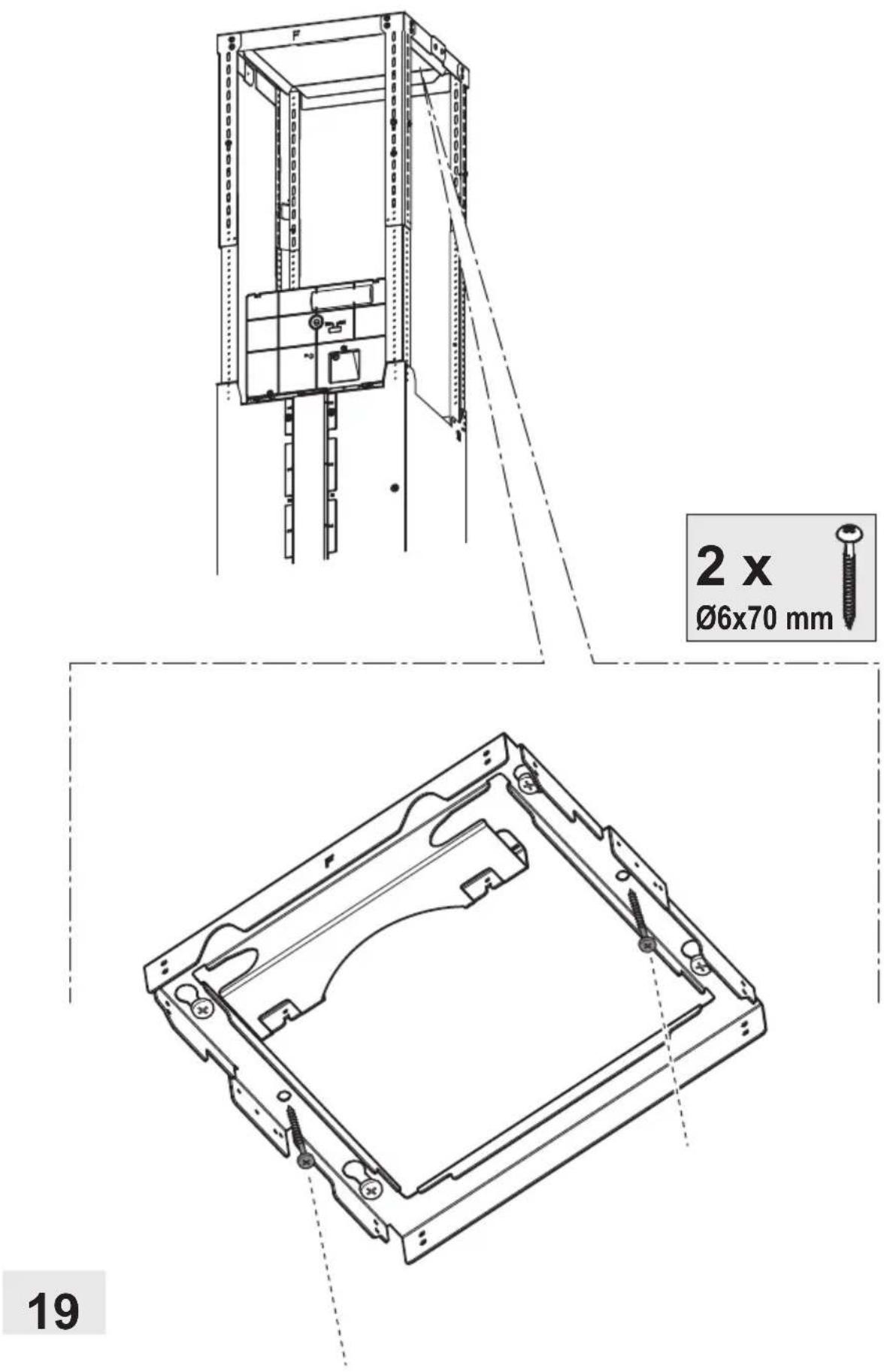
natural_image
Simple line drawing of a house with a circular arrow inside, symbolizing refresh or cycle (no text or symbols)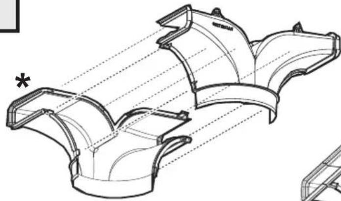
natural_image
Technical line drawing of a mechanical component with multiple curved surfaces and alignment lines (no text or symbols)Clack!
natural_image
Technical line drawing of a V-groove pipe fitting (no text or symbols)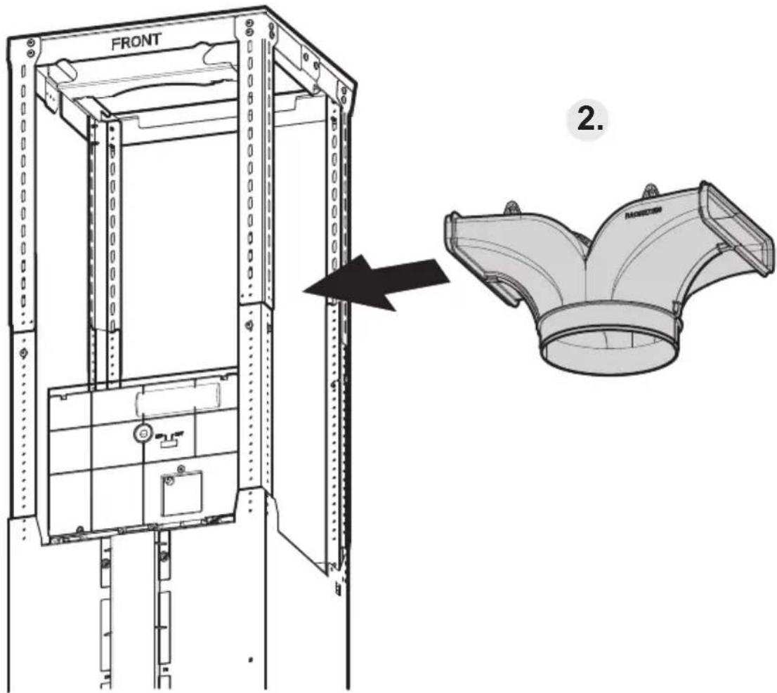
text_image
FRONT 2. RABORATION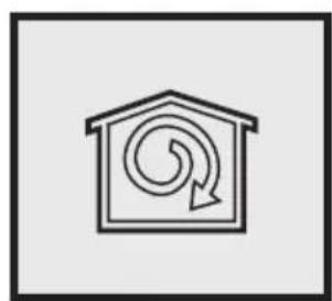
natural_image
Simple line drawing of a warehouse with a circular arrow inside, symbolizing refresh or move (no text or symbols)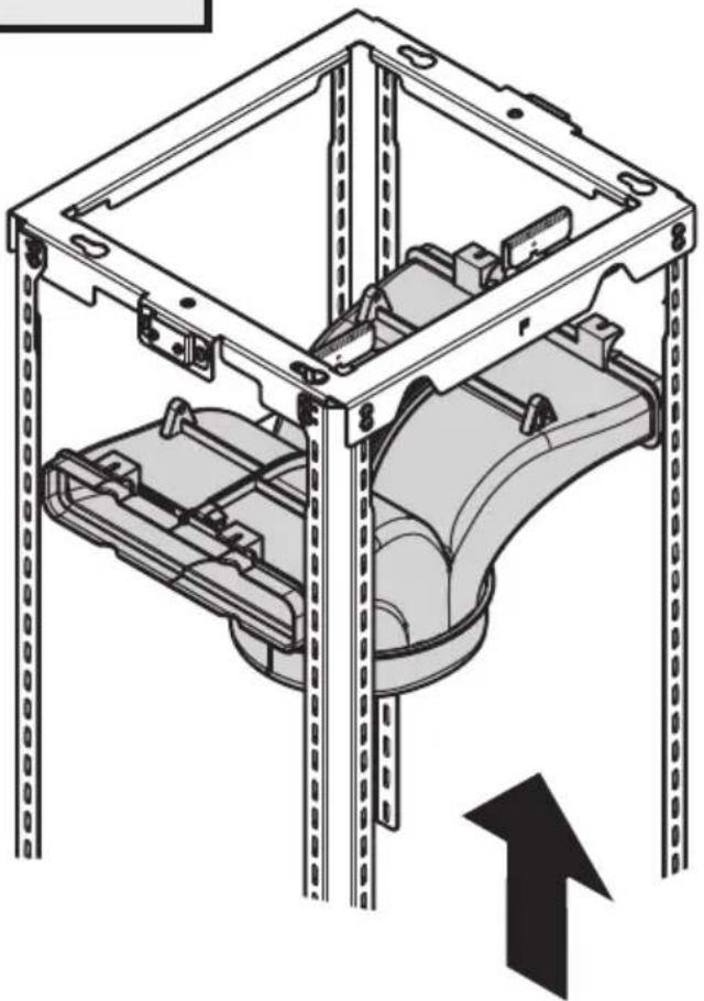
natural_image
Technical line drawing of a mechanical assembly with mounting brackets and a curved component, no text or symbols present.3.
text_image
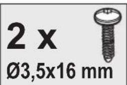
2 x Ø3,5x16 mm
text_image
Ø3,5x16 mm 4.20.1
natural_image
Technical line drawing of a vertical industrial lifting frame with structural supports and internal components (no text or symbols)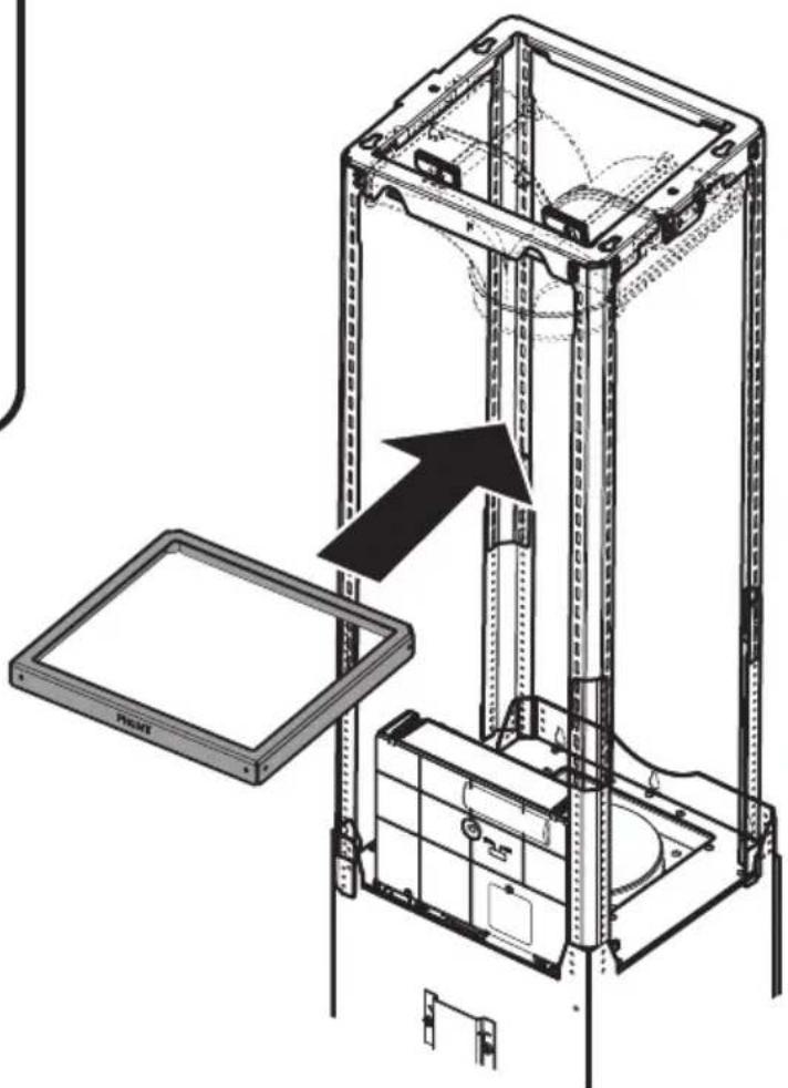
natural_image
Technical diagram of a server rack with an open panel and a highlighted component (no text or symbols)
natural_image
Simple line drawing of a hand holding a document or paper (no text or symbols)9
natural_image
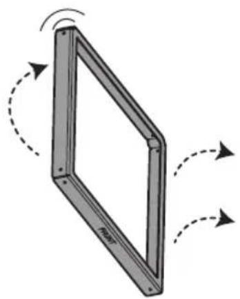
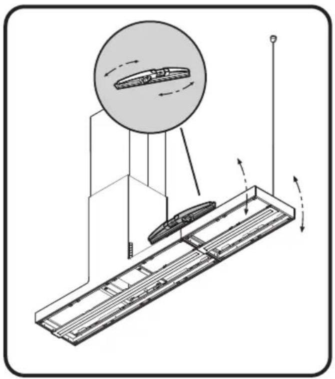
Diagram of a rectangular frame with curved arrows indicating rotational motion (no text or symbols)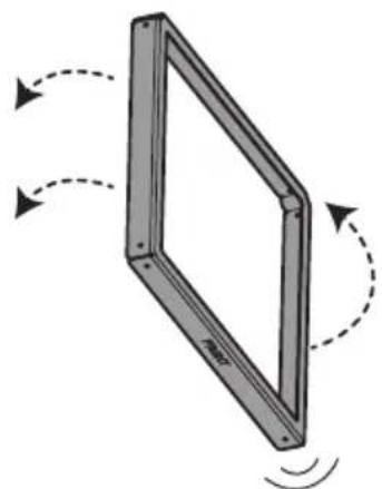
natural_image
Diagram of a rectangular frame with dashed arrows indicating rotational motion (no text or symbols)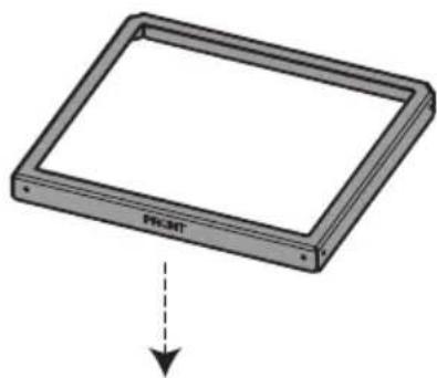
text_image
PR.NET8x
∅3,5x9,5 mm
text_image
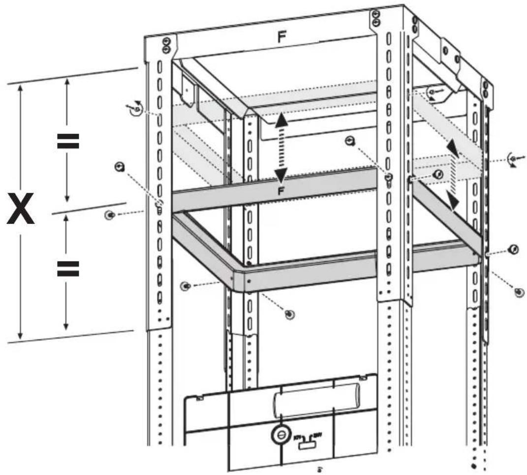
F X = = = F + - + + + + + + + + + + + + + + + + + + + + + + + + + + + + + + + + + + + + + + + + + + + + + + + + + + + + + + + + + + + + + + + + + + + + + + + + + + + + + + + + + + + +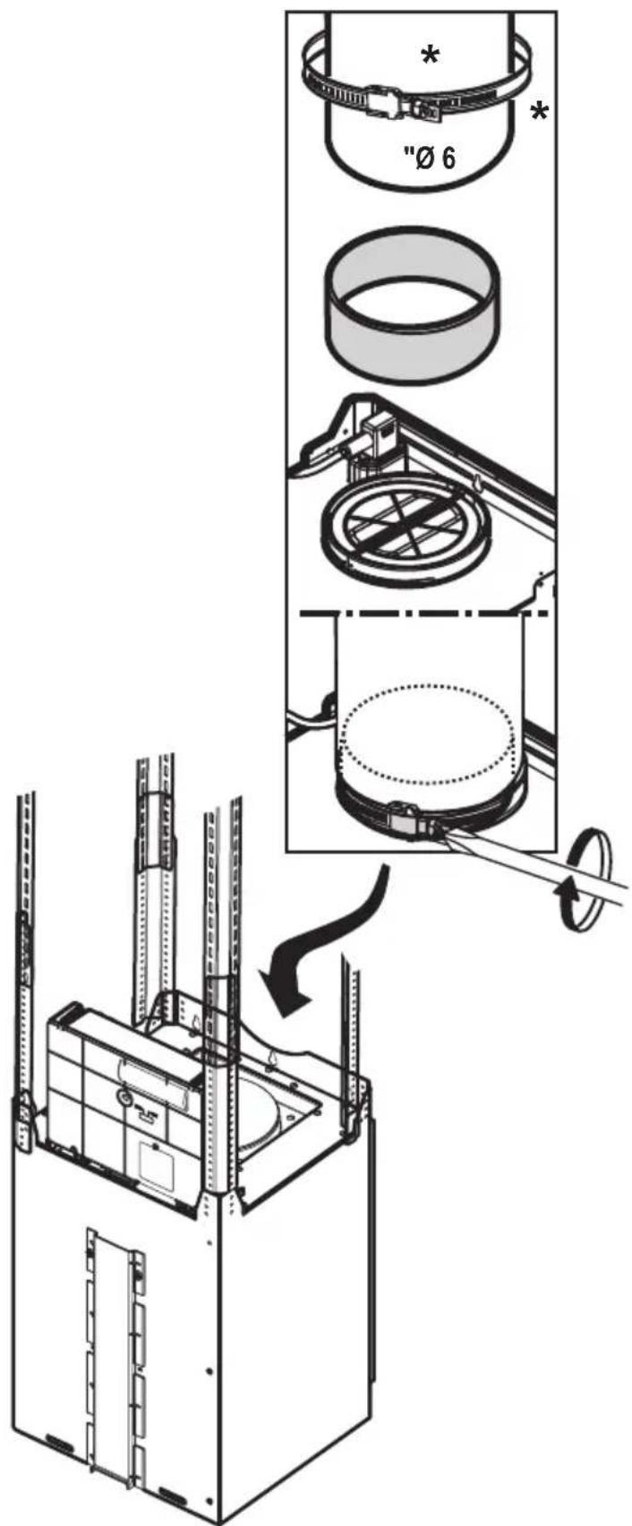
text_image
"Ø 6"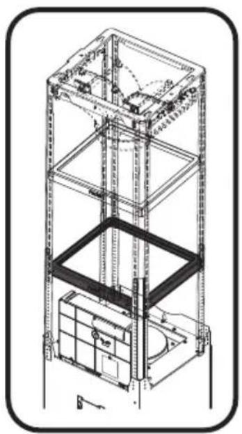
natural_image
Technical line drawing of a multi-level industrial lifting or storage unit structure (no text or symbols)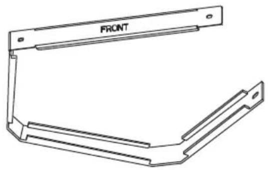
natural_image
Technical line drawing of a mechanical bracket with 'FRONT' label (no other text or symbols)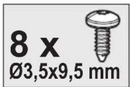
text_image
8 x Ø3,5x9,5 mm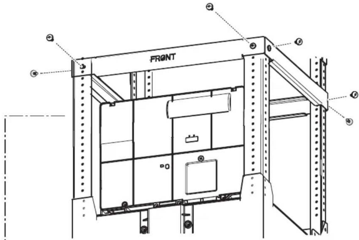
text_image
FRONT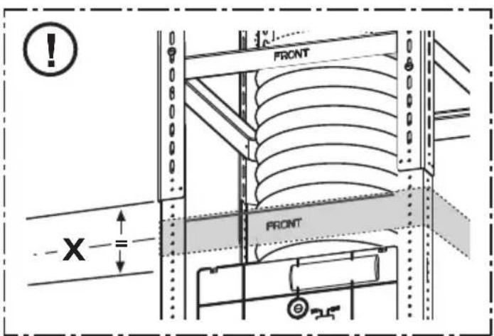
text_image
FRONT FRONT X =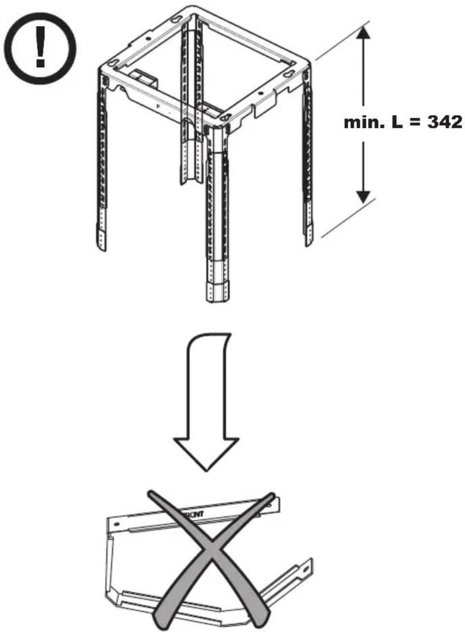
text_image
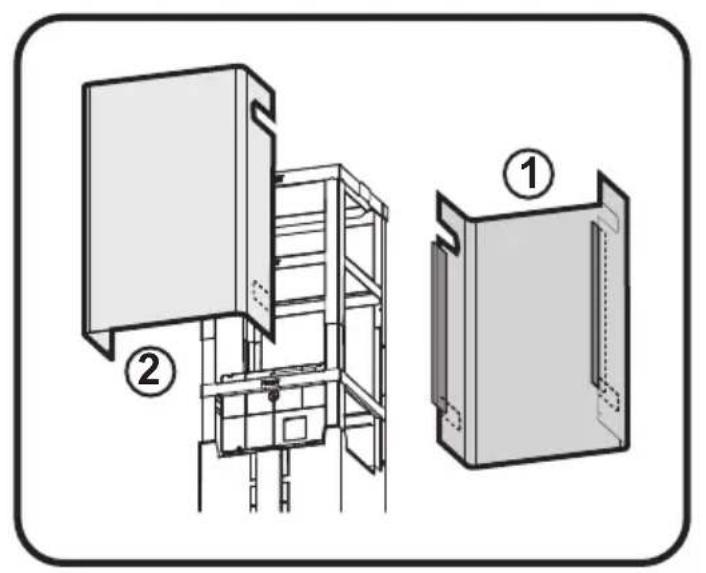
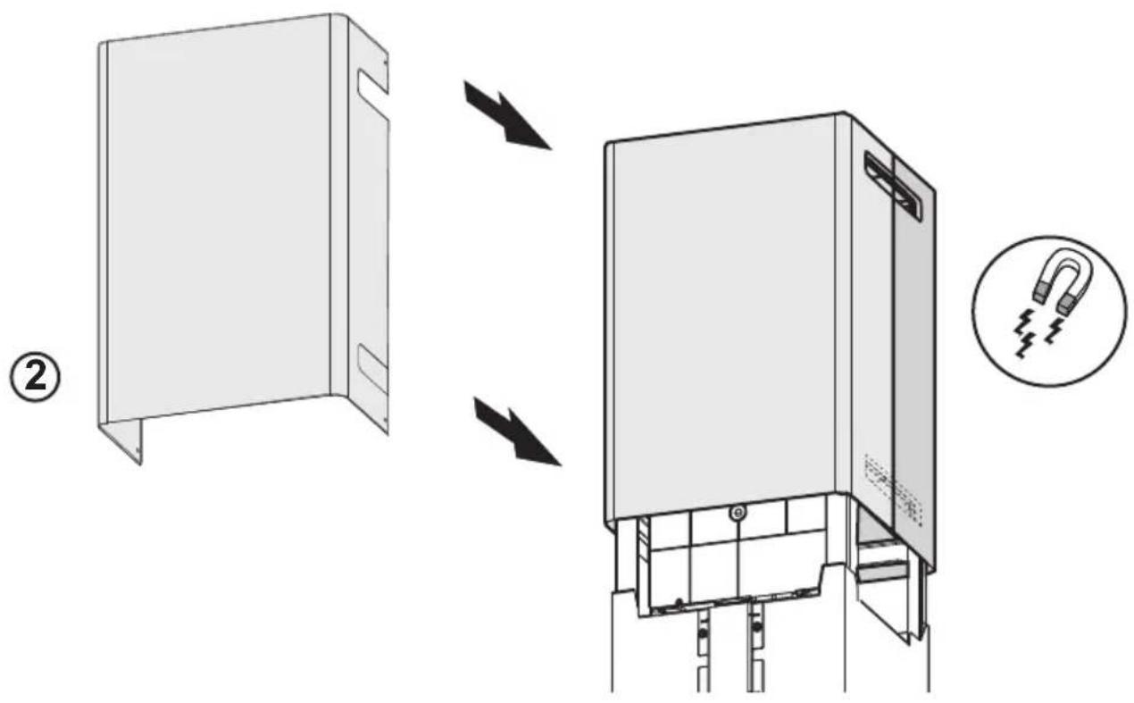
Technical diagram showing two views of a multi-level industrial cabinet or storage unit with labeled components ① and ②.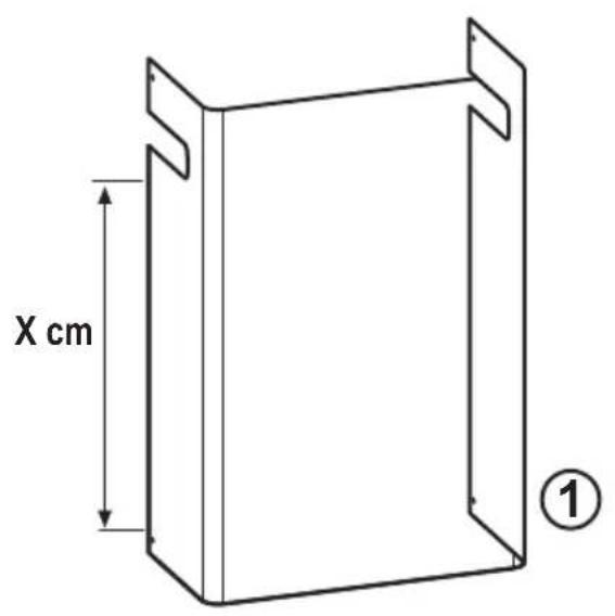
text_image
X cm ①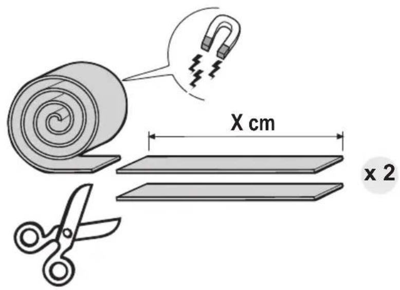
text_image
X cm x 2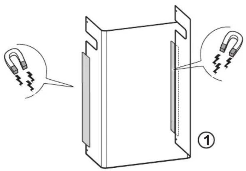
text_image
Diagram showing a device with two spring-loaded clips and a magnified view of the interior panel, labeled with number ①.
natural_image
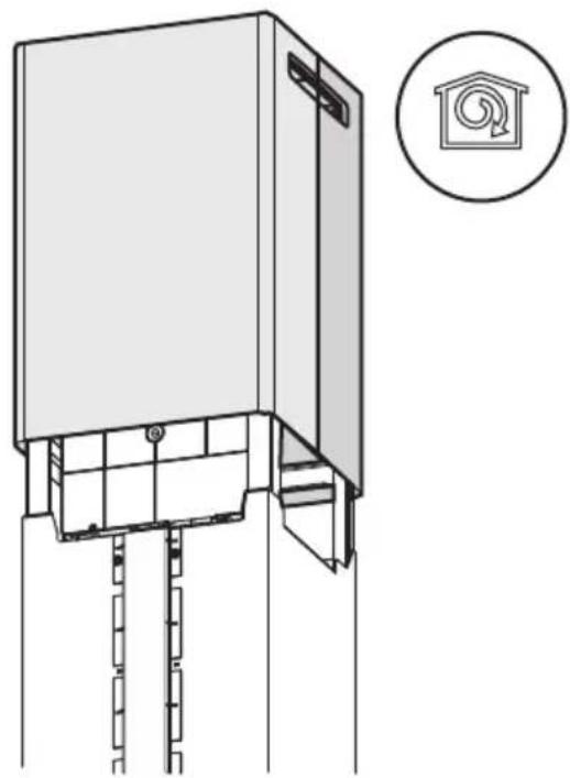
Technical line drawing of a cabinet or elevator assembly with a circular icon showing a house with a circular symbol (no text or labels present)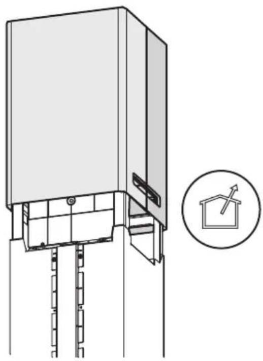
natural_image
Technical line drawing of a vertical elevator shaft assembly with a circular inset showing a house symbol (no text or labels)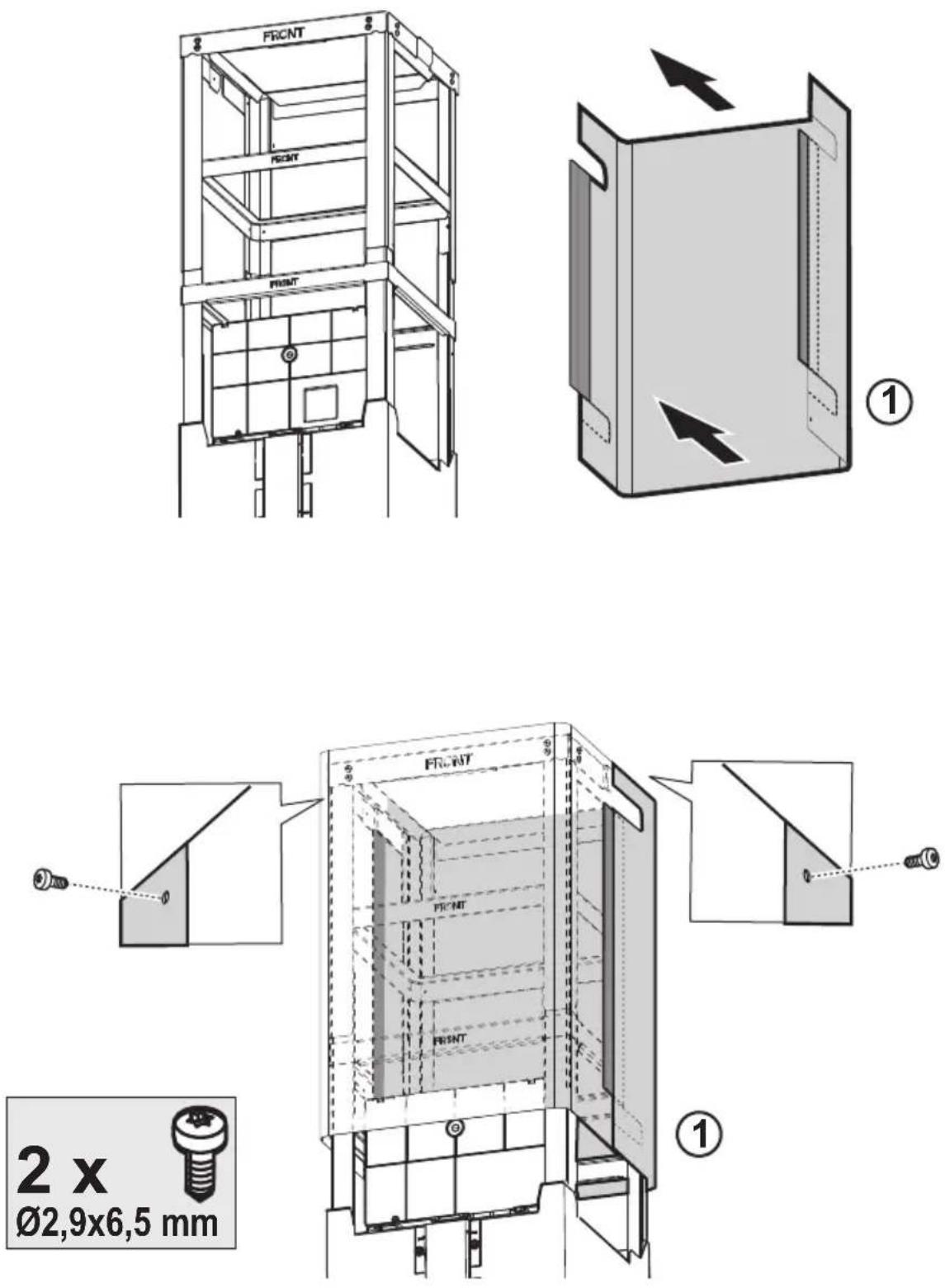
text_image
Technical diagram showing a door frame assembly and its internal structure with a U-shaped component, labeled with step number ②.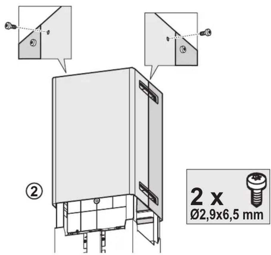
text_image
② 2 x Ø2,9x6,5 mm
natural_image
Technical line drawing of a mechanical assembly with a bracket and internal components (no text or symbols)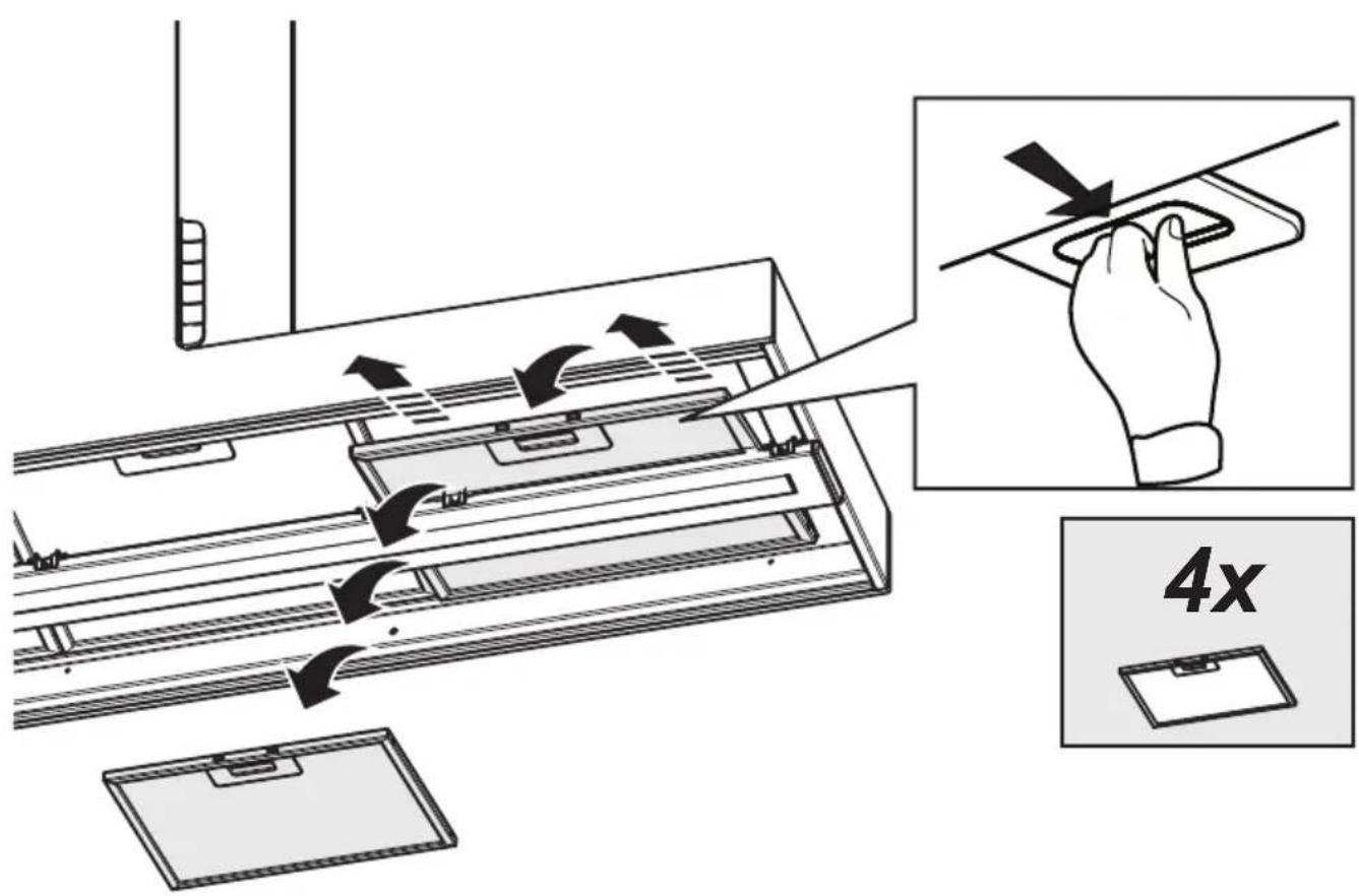
text_image
Diagram illustrating a 4x speed limit mechanism in a refrigerator drawer, showing hand positioning and directional arrows.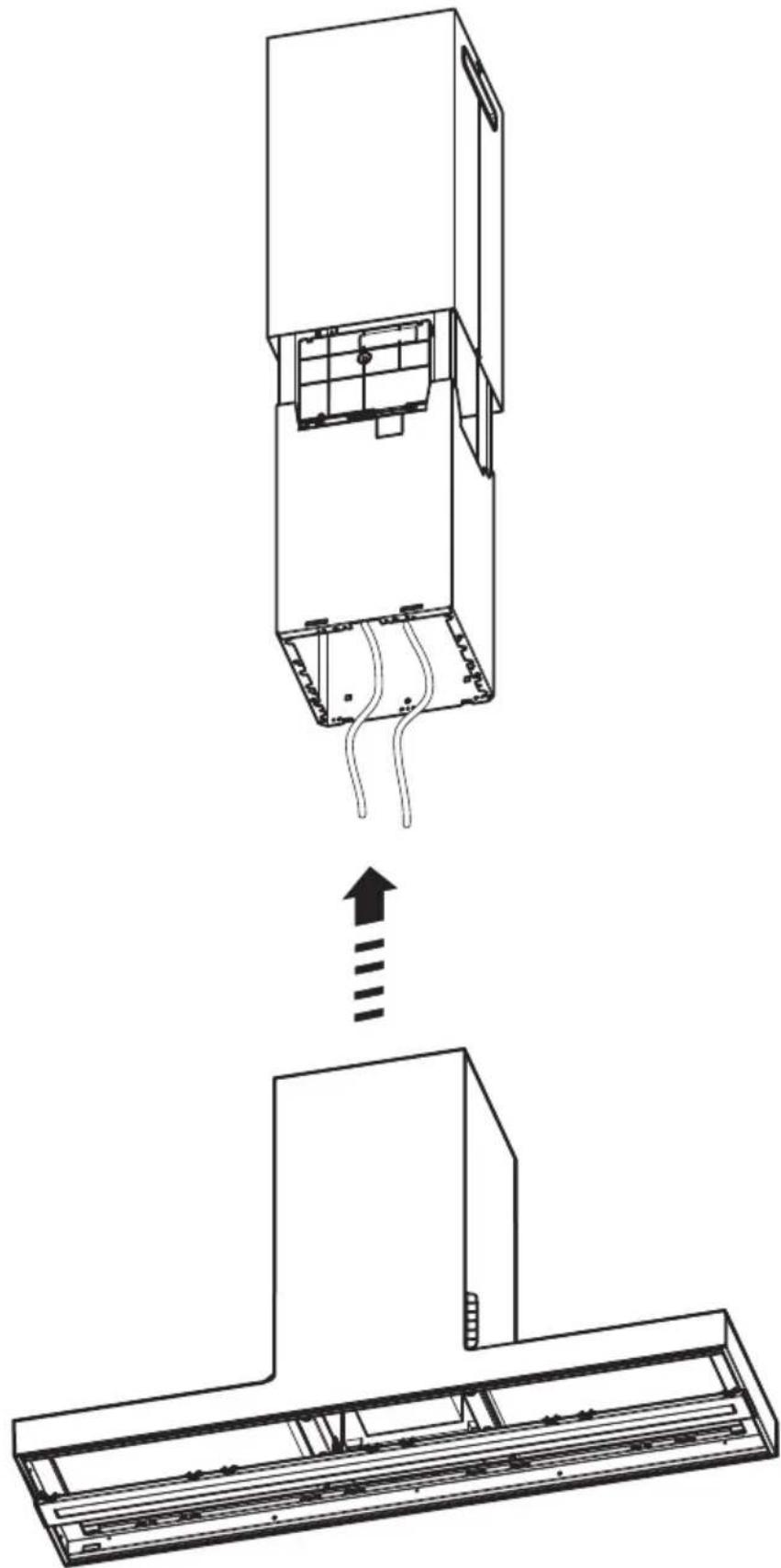
natural_image
Technical line drawing of a device assembly showing internal components and a downward arrow indicating motion (no text or symbols present)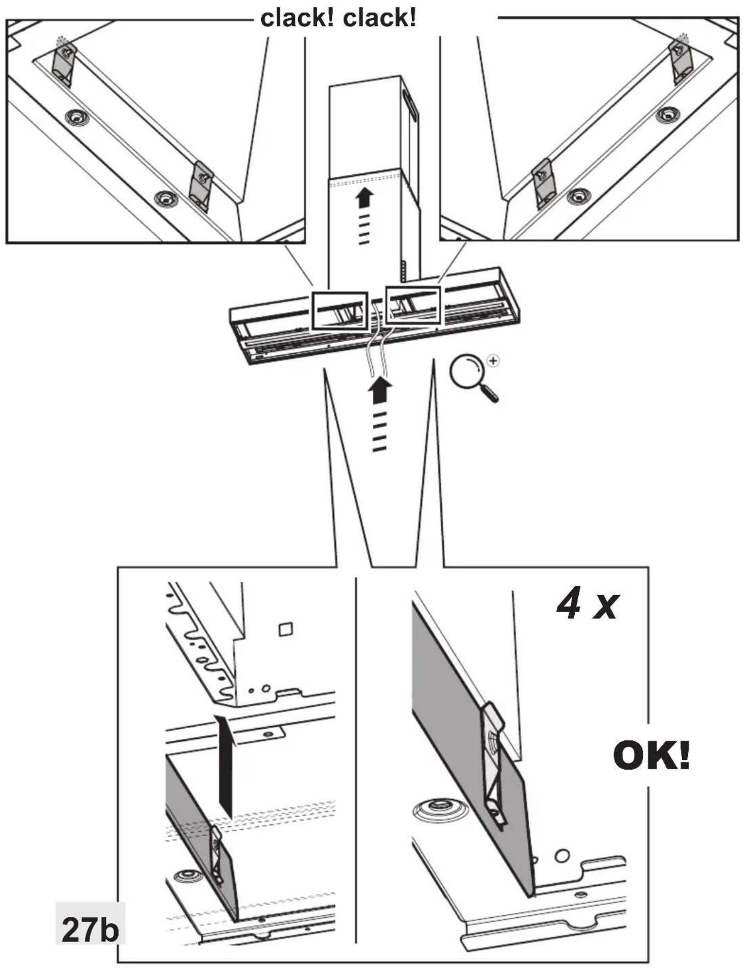
text_image
clack! clack! 4 x OK! 27b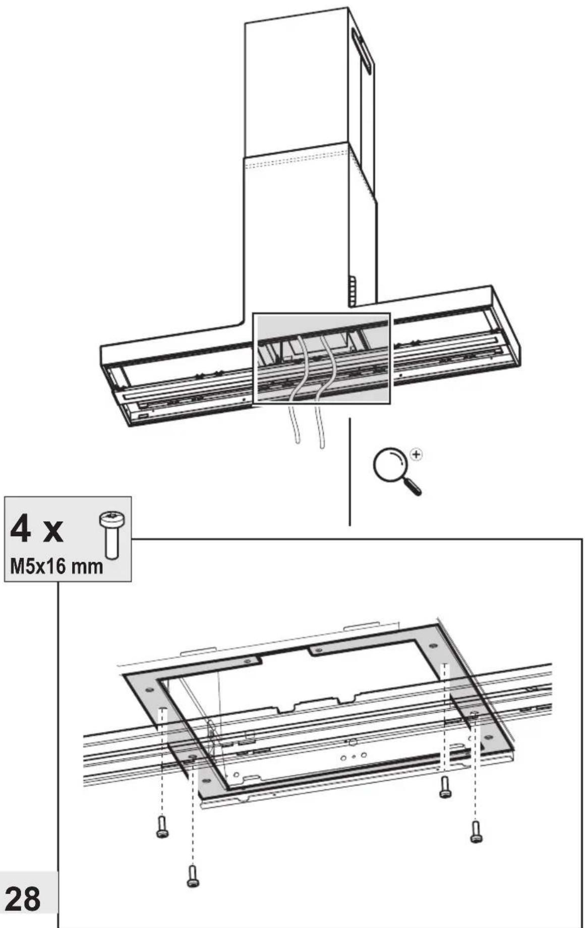
4 x
M5x16 mm
natural_image
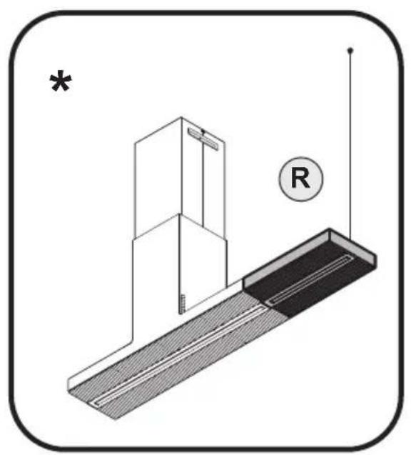
Technical diagram showing a mechanical assembly with a bracket and a labeled component R (no text or symbols present)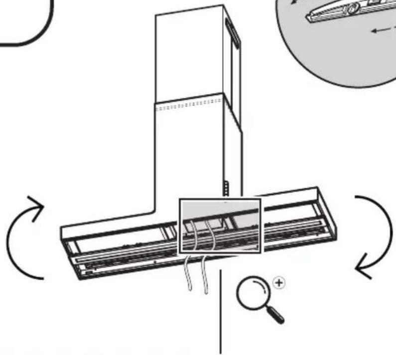
natural_image
Diagram of a server rack with internal components and directional arrows indicating rotation (no text or symbols)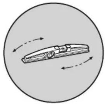
natural_image
Diagram of a car inside a circle with motion arrows indicating speed or direction (no text or symbols)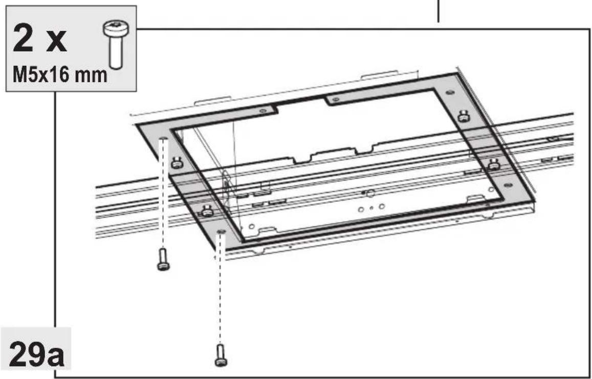
text_image
2 x M5x16 mm 29a
natural_image
Technical line drawing of a mechanical assembly with a bracket and shaft, no text or symbols present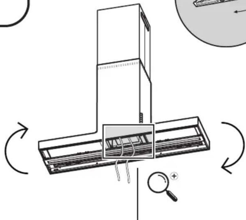
natural_image
Diagram of a server rack with internal components and directional arrows indicating rotation (no text or symbols)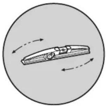
natural_image
Diagram of a car with motion arrows indicating speed or direction (no text or symbols)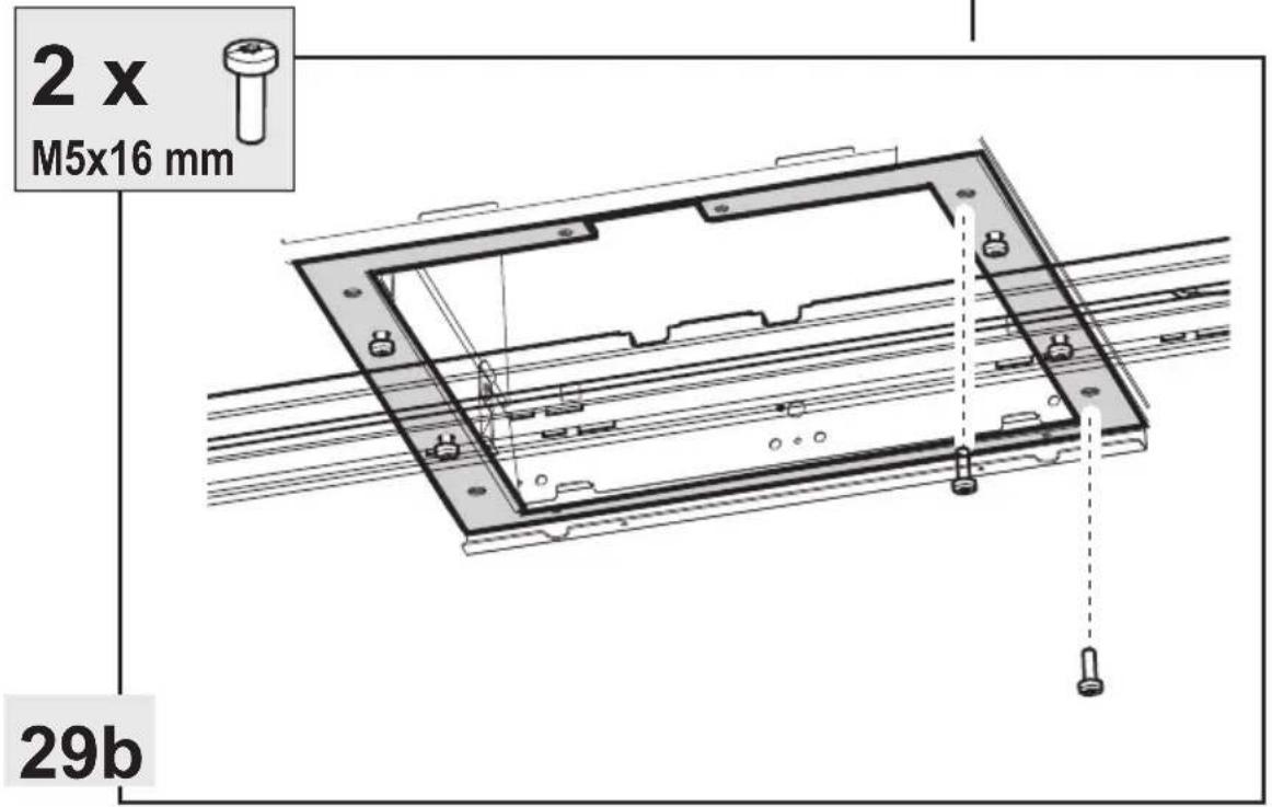
text_image
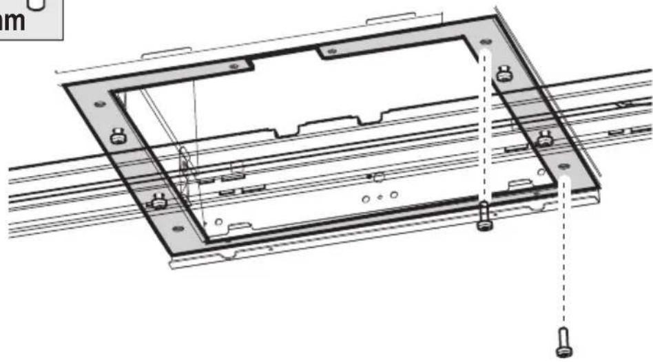
2 x M5x16 mm 29b2x
M5x16 mm
natural_image
Technical line drawing of a mechanical assembly with mounting holes and structural beams (no text or symbols)29b
text_image
Technical diagram showing installation of an air conditioner unit with cable routing and inspection, including a magnifying glass and close-up views labeled 'OK'.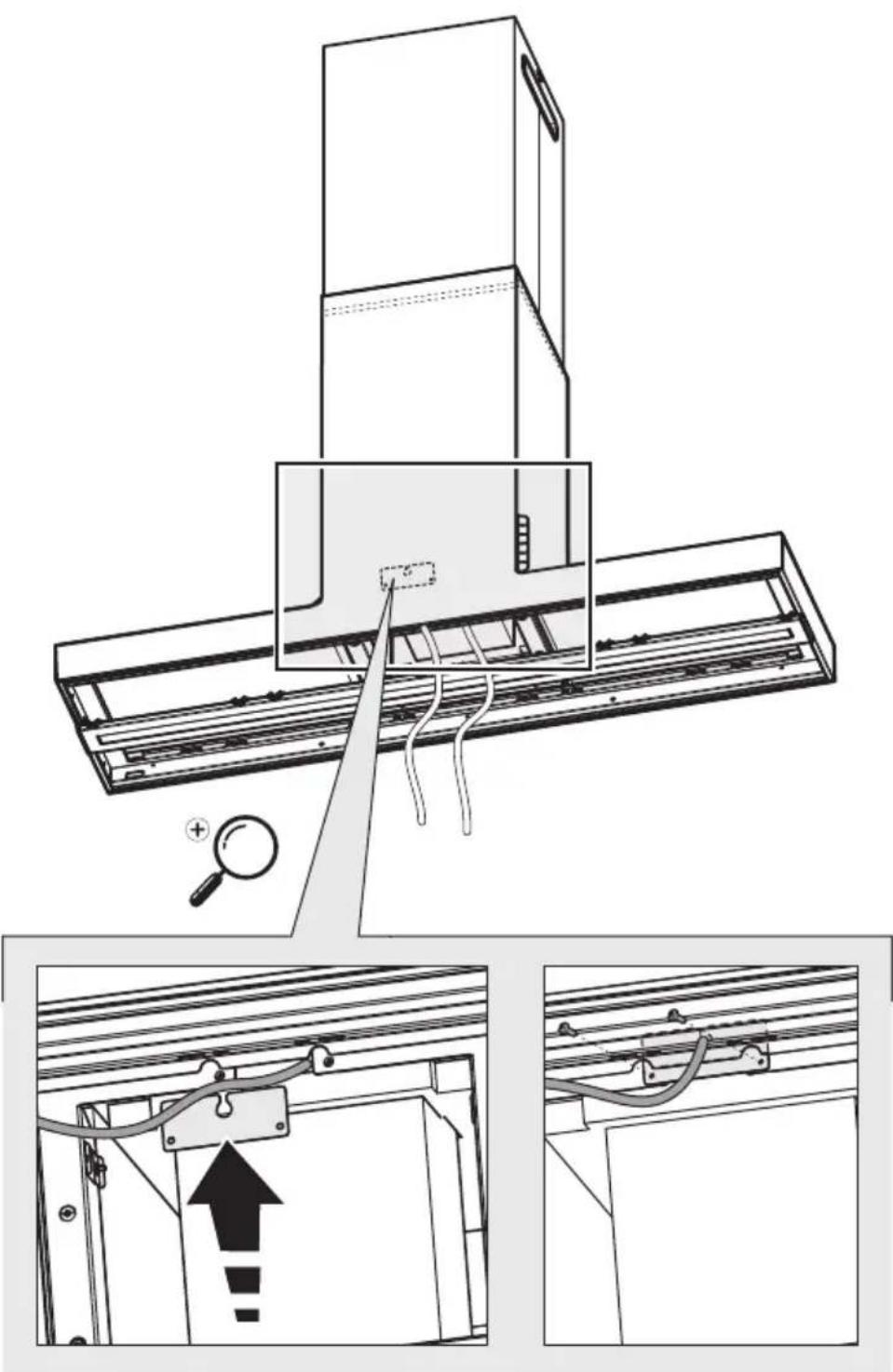
2x
∅3,5x9,5 mm
natural_image
Technical diagram showing a mechanical assembly with a bracket and a vertical rod, no text or symbols present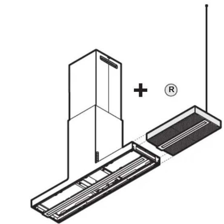
natural_image
Technical line drawing of a device with a plus sign and antenna, no text or symbols present
33-35-36-37-38-39-40-41-41a-42-43-44-45-46-48-49
natural_image
Technical line drawing of a mechanical or architectural component with a labeled section (L), no readable text or symbols present.
natural_image
Technical line drawing of a device with a base panel and a vertical panel, showing no text or symbols.
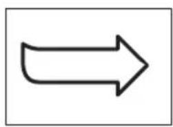
34-34a-35-36-37-38-39-40-41-41a-42-43-44-45-47-48-49
natural_image
Technical diagram of a mechanical assembly with a bracket and a vertical rod, no text or symbols present
natural_image
Technical line drawing of a server rack with an inset magnified view showing internal components (no text or symbols)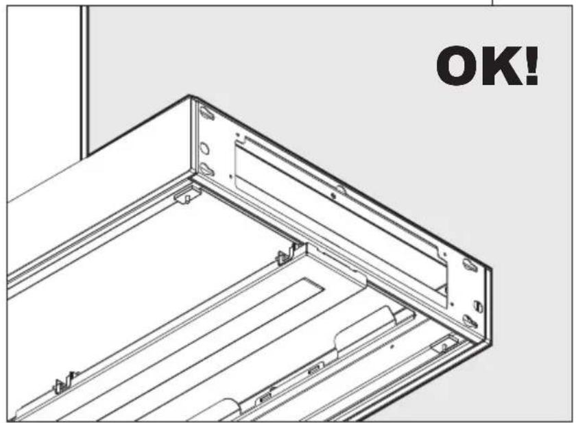
natural_image
Technical line drawing of a mechanical assembly with mounting brackets and mounting holes (no text or symbols)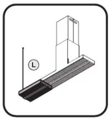
natural_image
Technical diagram of a mechanical assembly with a labeled component (no text or symbols present)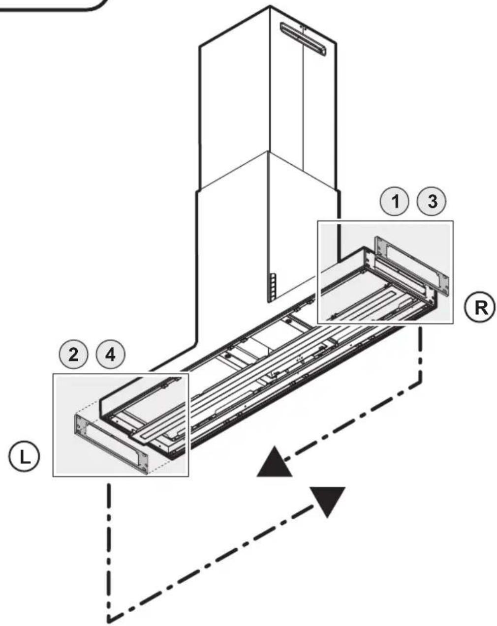
text_image
Technical diagram of a refrigerated refrigerator with labeled components and directional arrows indicating assembly or movement.
natural_image
Simple black arrow pointing right on white background (no text or symbols)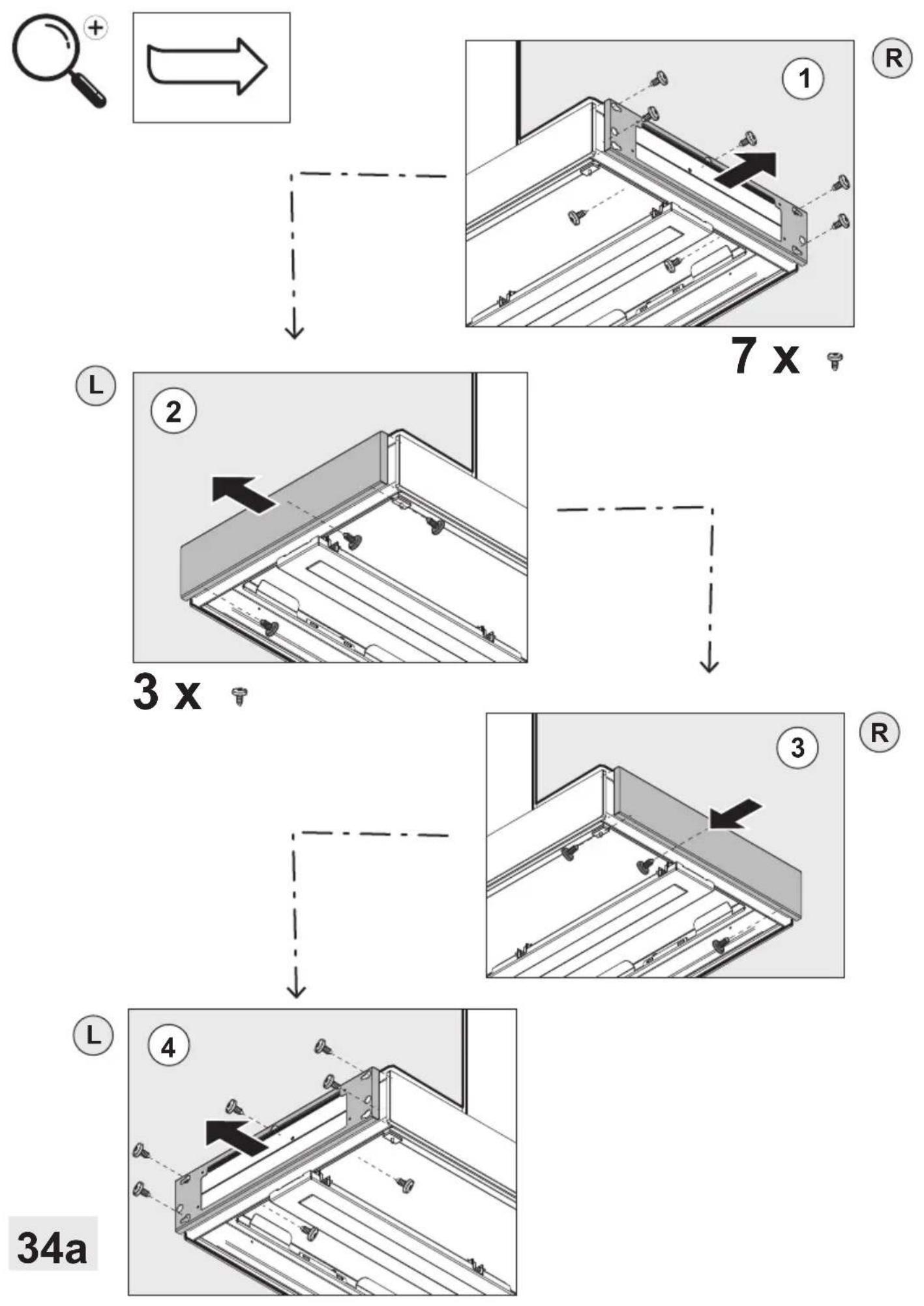
text_image
1 x Ø 8mm 103 cm 1x 1x 1x a. b. c.
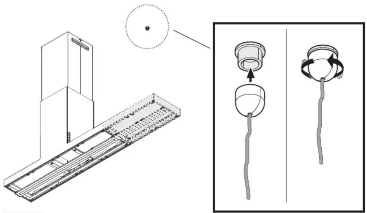
text_image
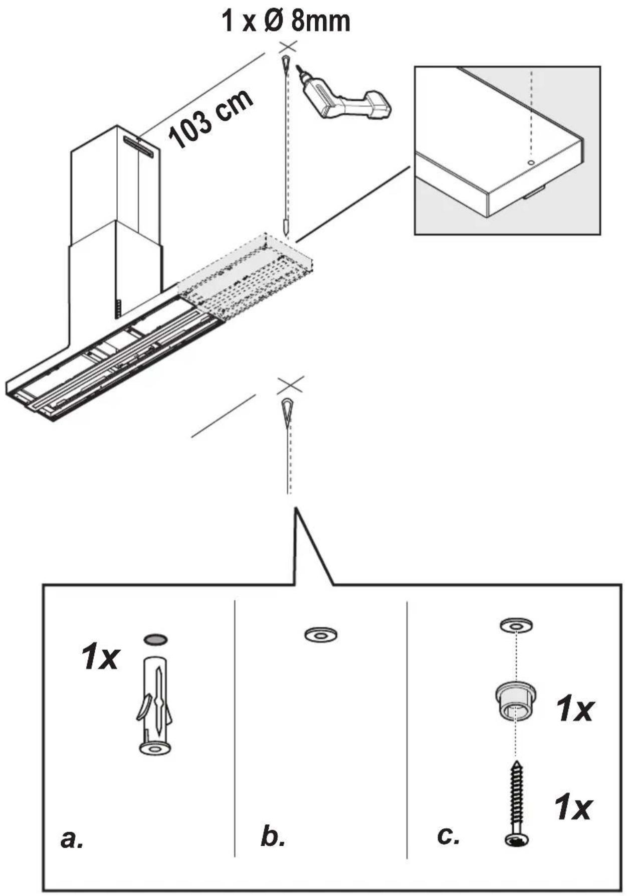
Technical diagram showing a mechanical assembly with a magnified inset illustrating the process of lifting a component.37
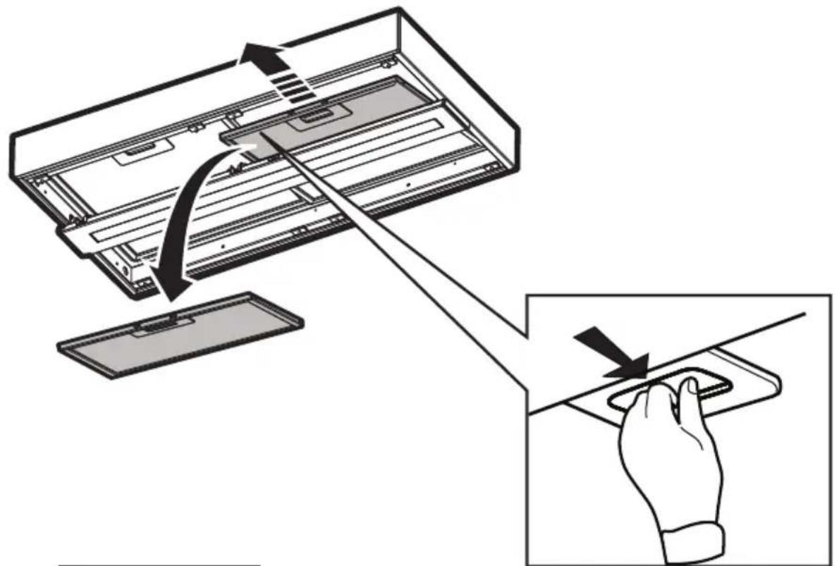
text_image
Diagram illustrating a hand pressing down a device component with directional arrows indicating motion or force.
text_image
2x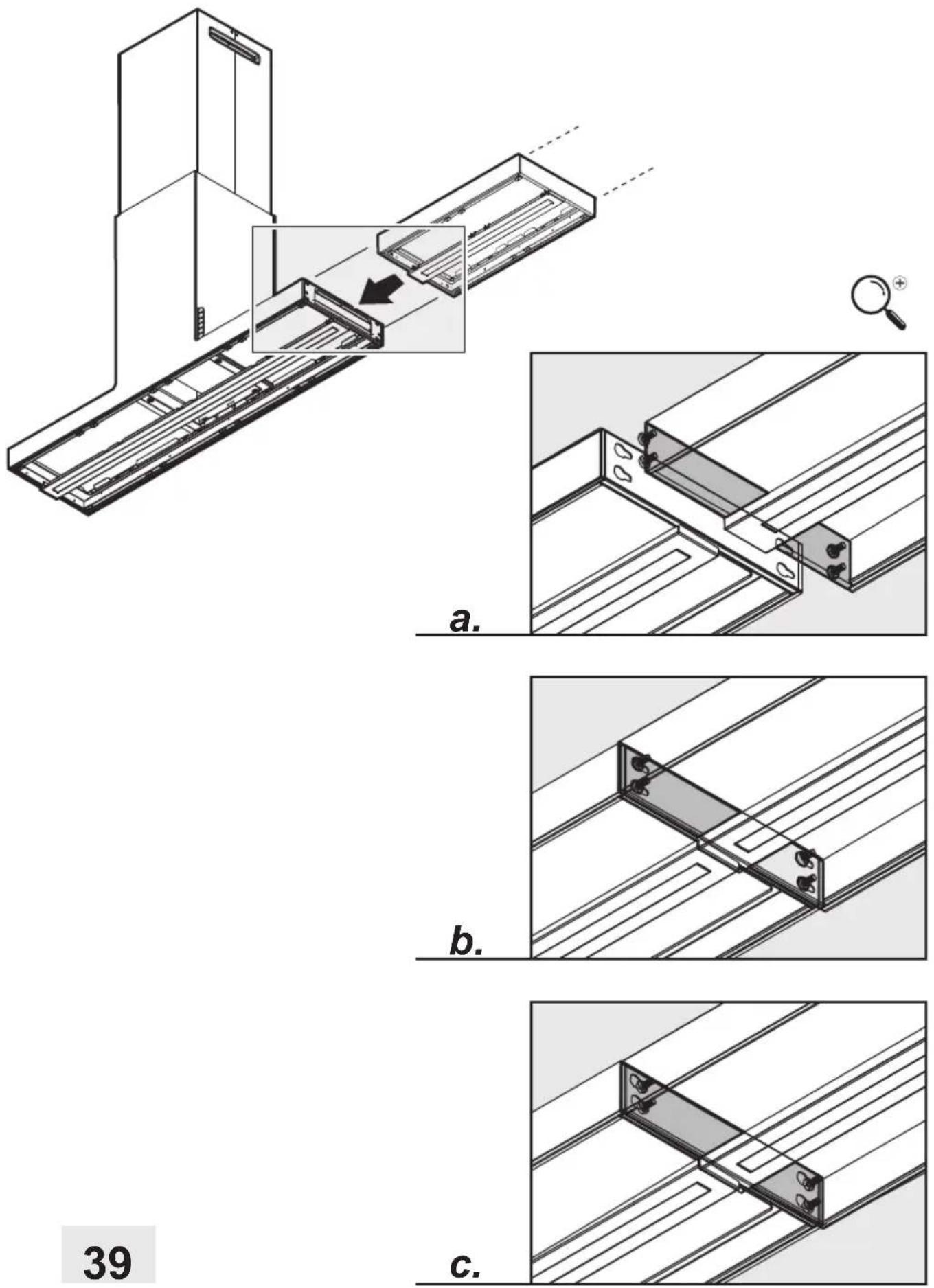
natural_image
Technical line drawing of a mechanical assembly with a magnified inset showing internal components (no text or symbols)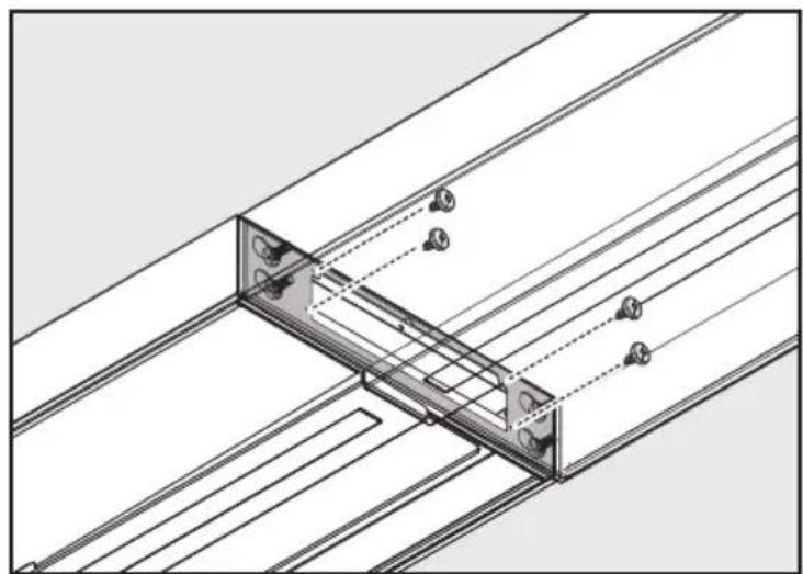
natural_image
Technical line drawing of a structural assembly with beams and supports (no text or symbols)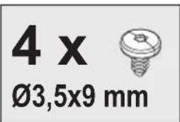
text_image
4 x Ø3,5x9 mm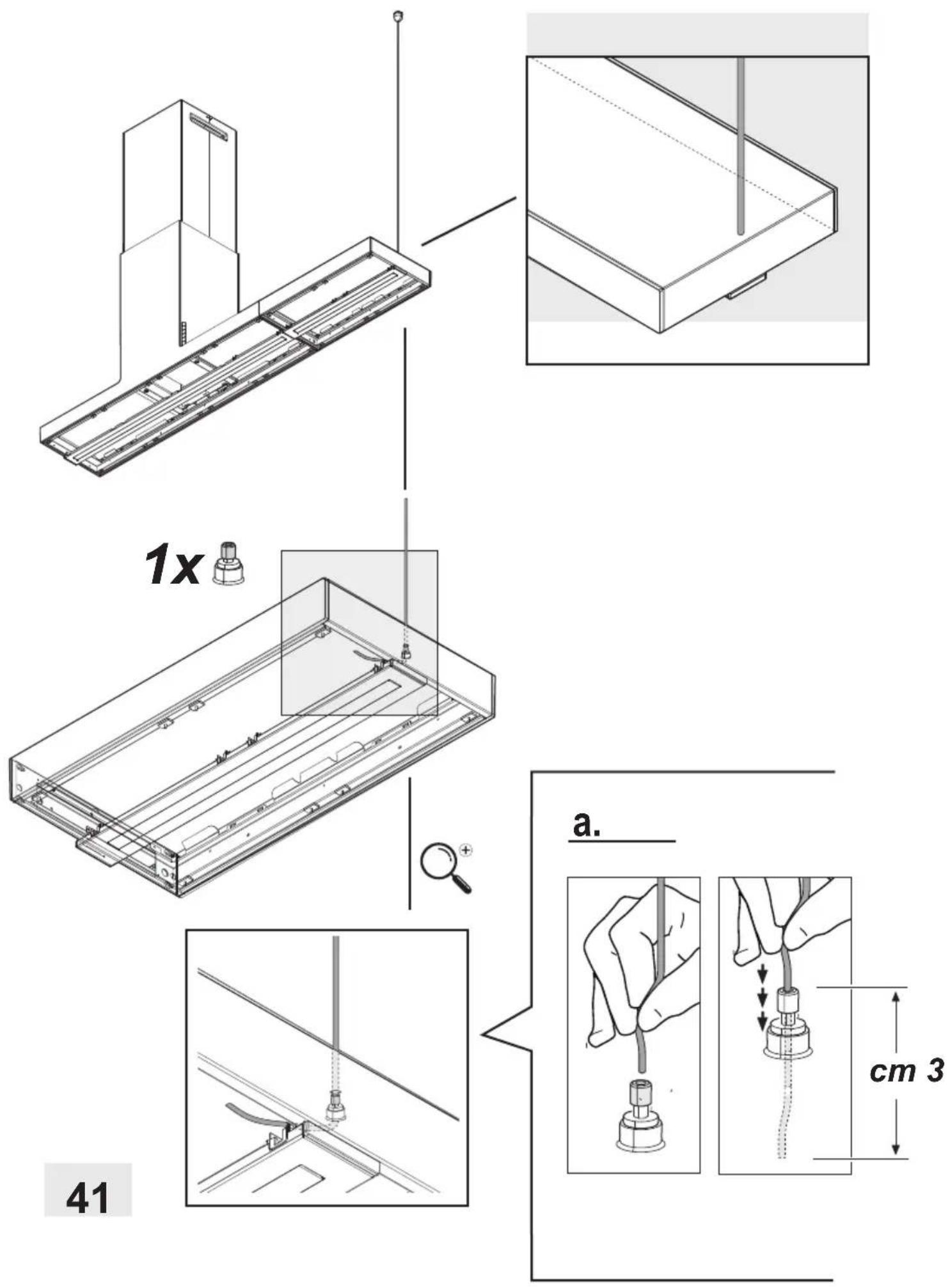
natural_image
Technical diagram of a ship's deck structure with motion arrows and a circular inset showing a boat's view (no text or symbols)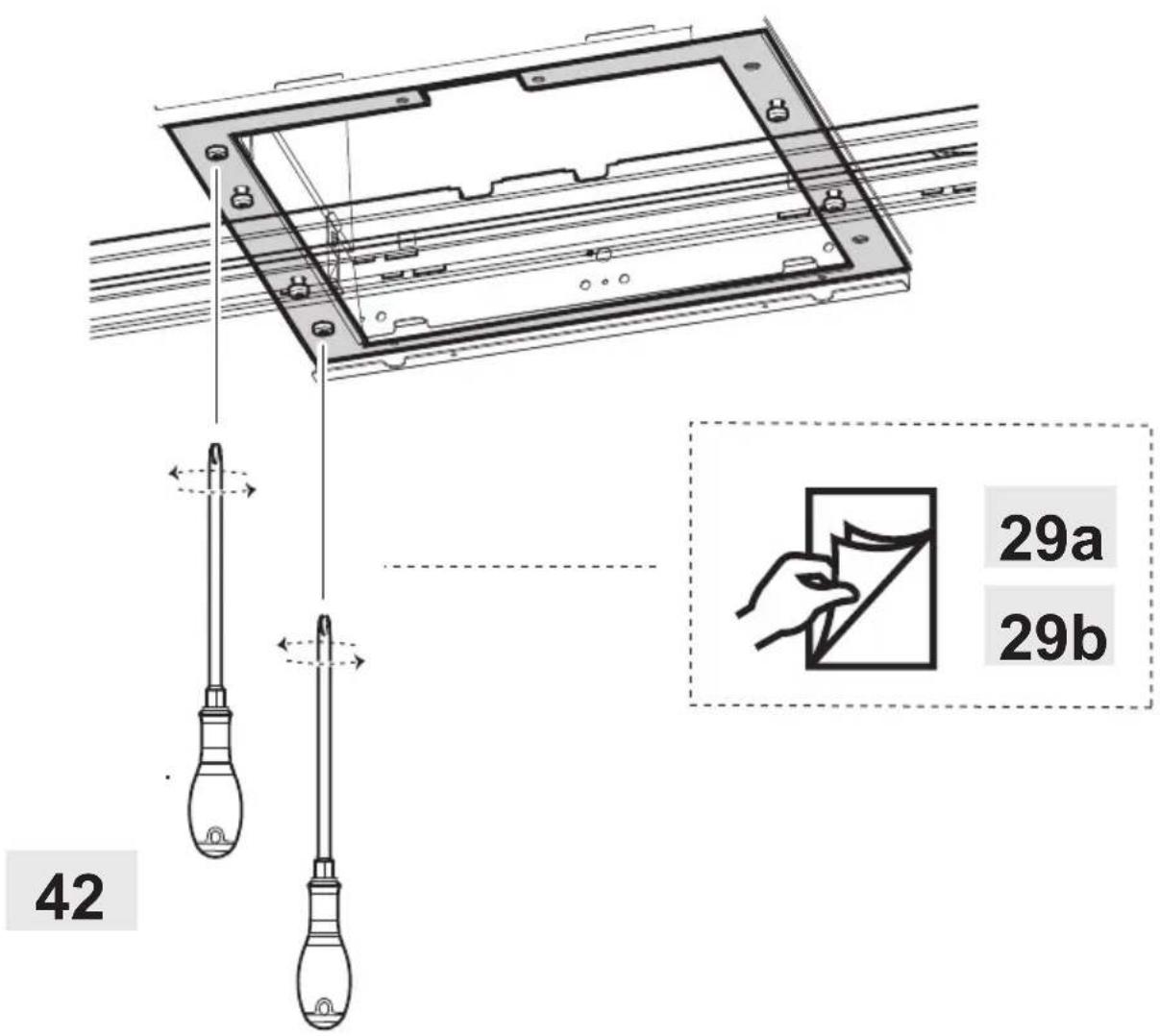
text_image
42 29a 29b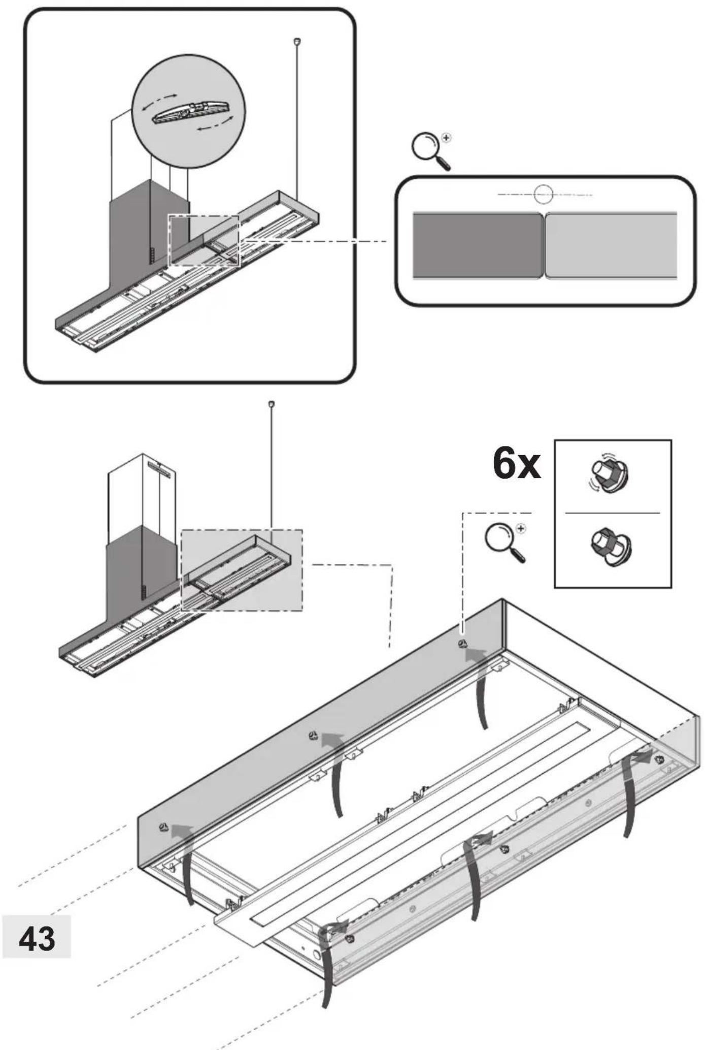
natural_image
Technical diagram of a rectangular electronic device with internal channels and directional arrows indicating movement (no text or symbols)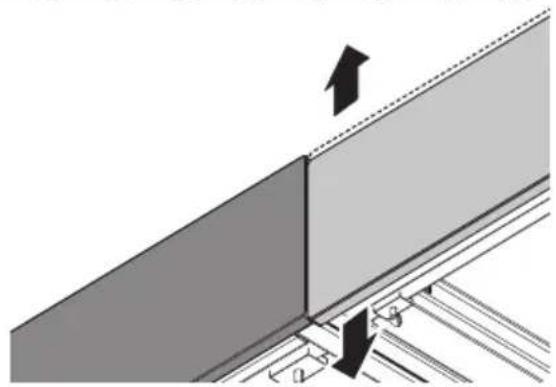
natural_image
Diagram showing a structural joint with an upward arrow indicating force or direction, no text or symbols present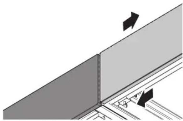
natural_image
Diagram of a structural joint or panel connection with arrows indicating direction (no text or symbols present)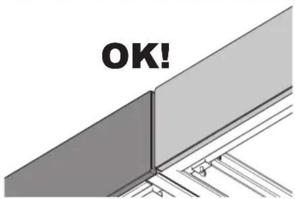
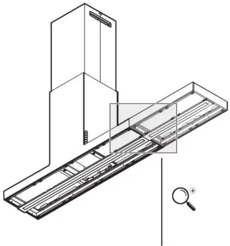
text_image
OK!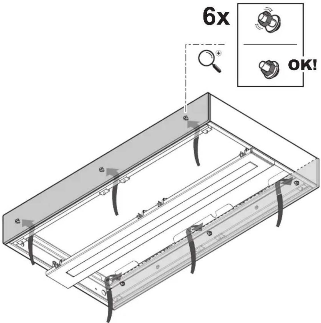
text_image
6x OK!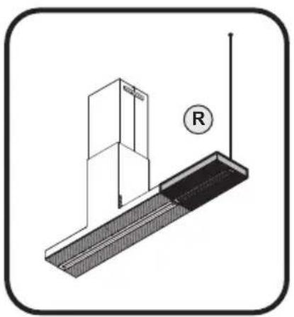
natural_image
Technical diagram showing a mechanical assembly with a bracket and a vertical rod, no text or symbols present.
natural_image
Technical line drawing of a mechanical assembly with two views (top and side), showing internal components and wiring connections without any text or symbols.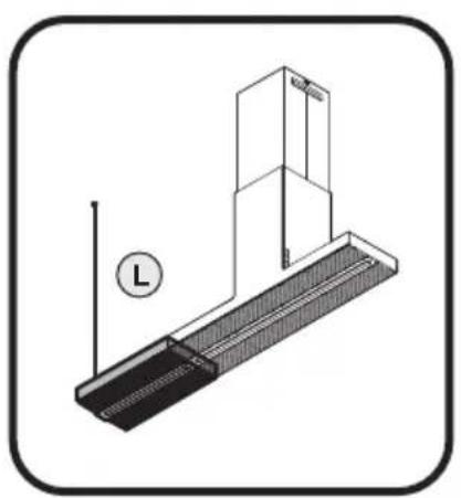
natural_image
Technical line drawing of a mechanical assembly with a vertical rod and base plate, no text or symbols present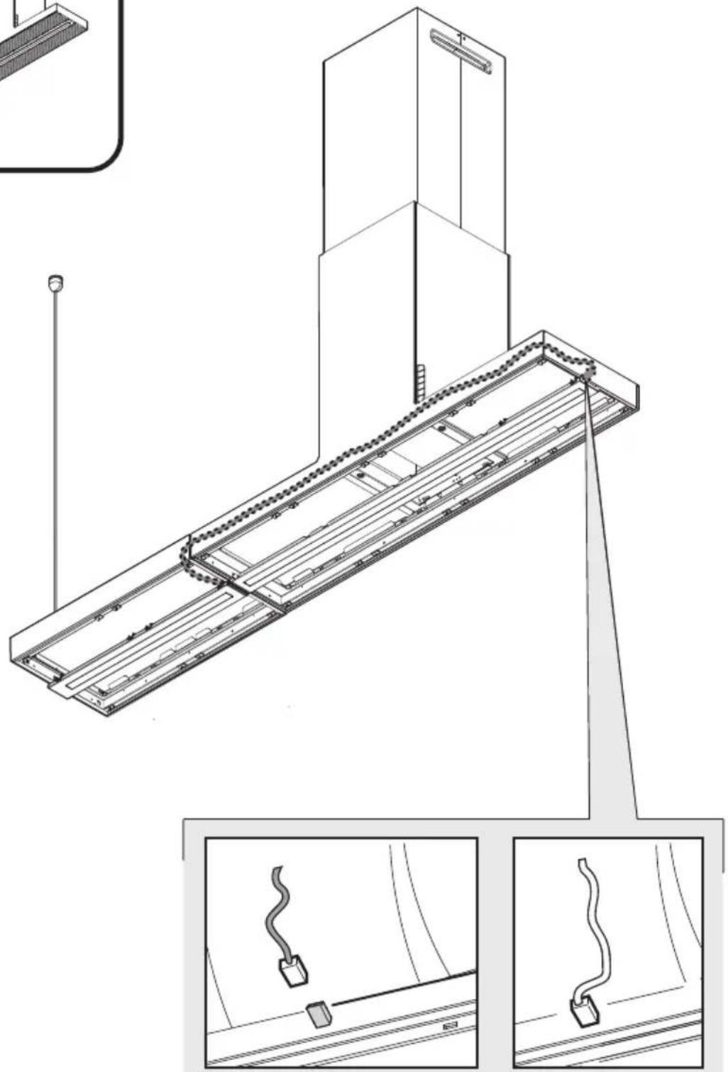
natural_image
Technical line drawing of a mechanical assembly with two views (top and side), no visible text or symbols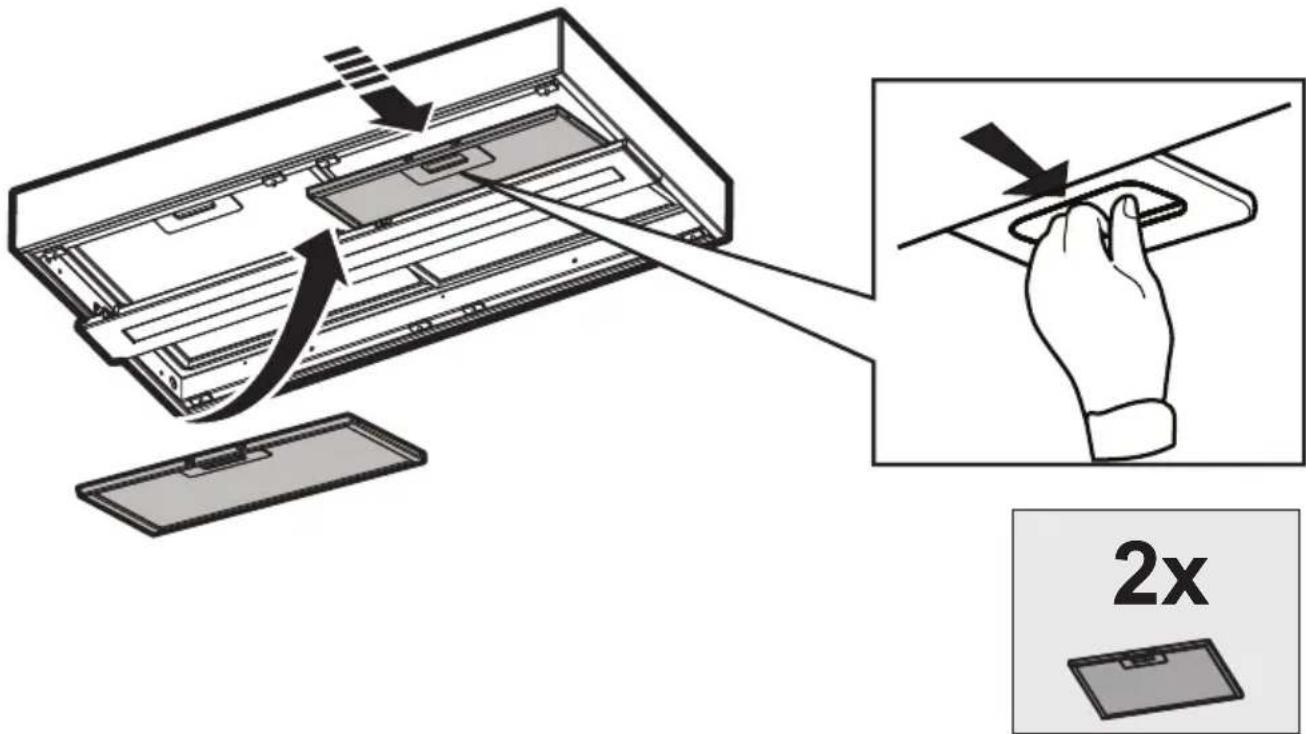
text_image
Diagram illustrating a 2x speed limit operation on an electronic device, showing hand positioning and cutting tool path.48
text_image
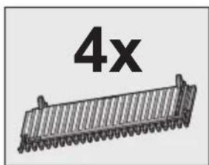
4x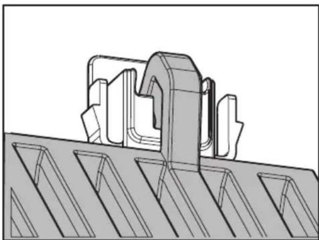
natural_image
Technical line drawing of a mechanical component with grooves and a central bracket (no text or symbols)
49
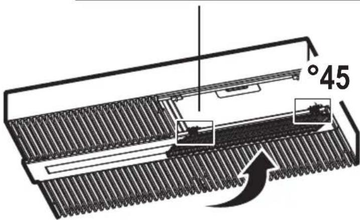
text_image
°45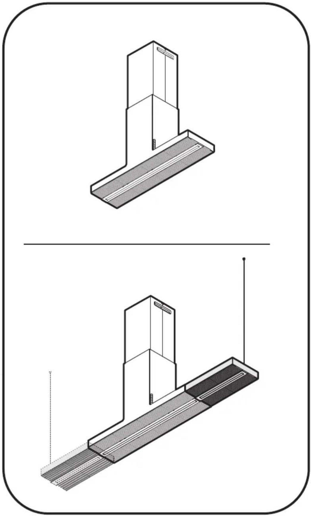
natural_image
Technical line drawing of a mechanical assembly with two views (top and side), showing internal components and a vertical pole (no text or symbols)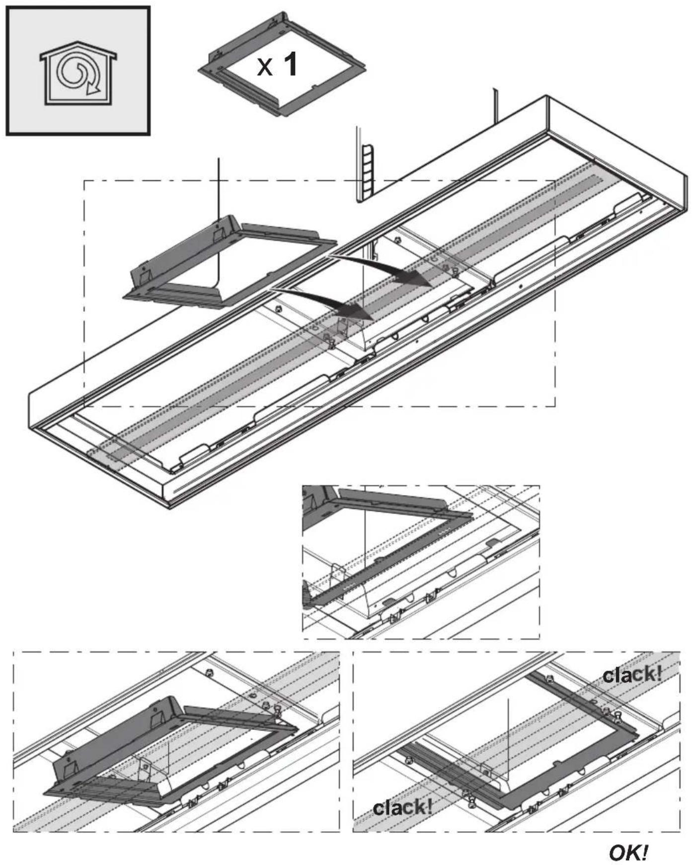
natural_image
Simple line drawing of a house with a circular arrow inside, symbolizing refresh or cycle (no text or symbols)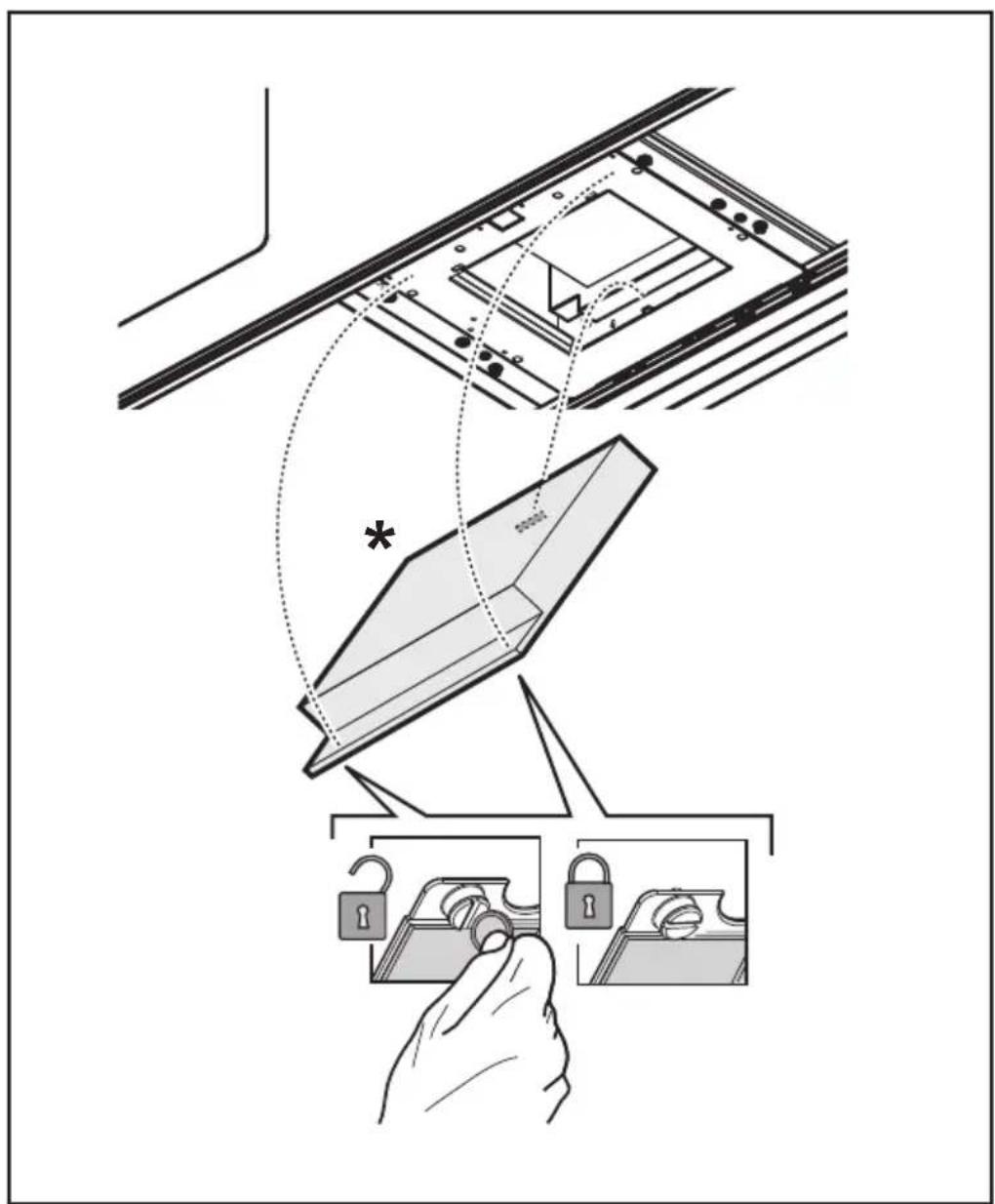
text_image
Diagram illustrating a lock mechanism with labeled components and lock states, showing hand positioning and lock state capture.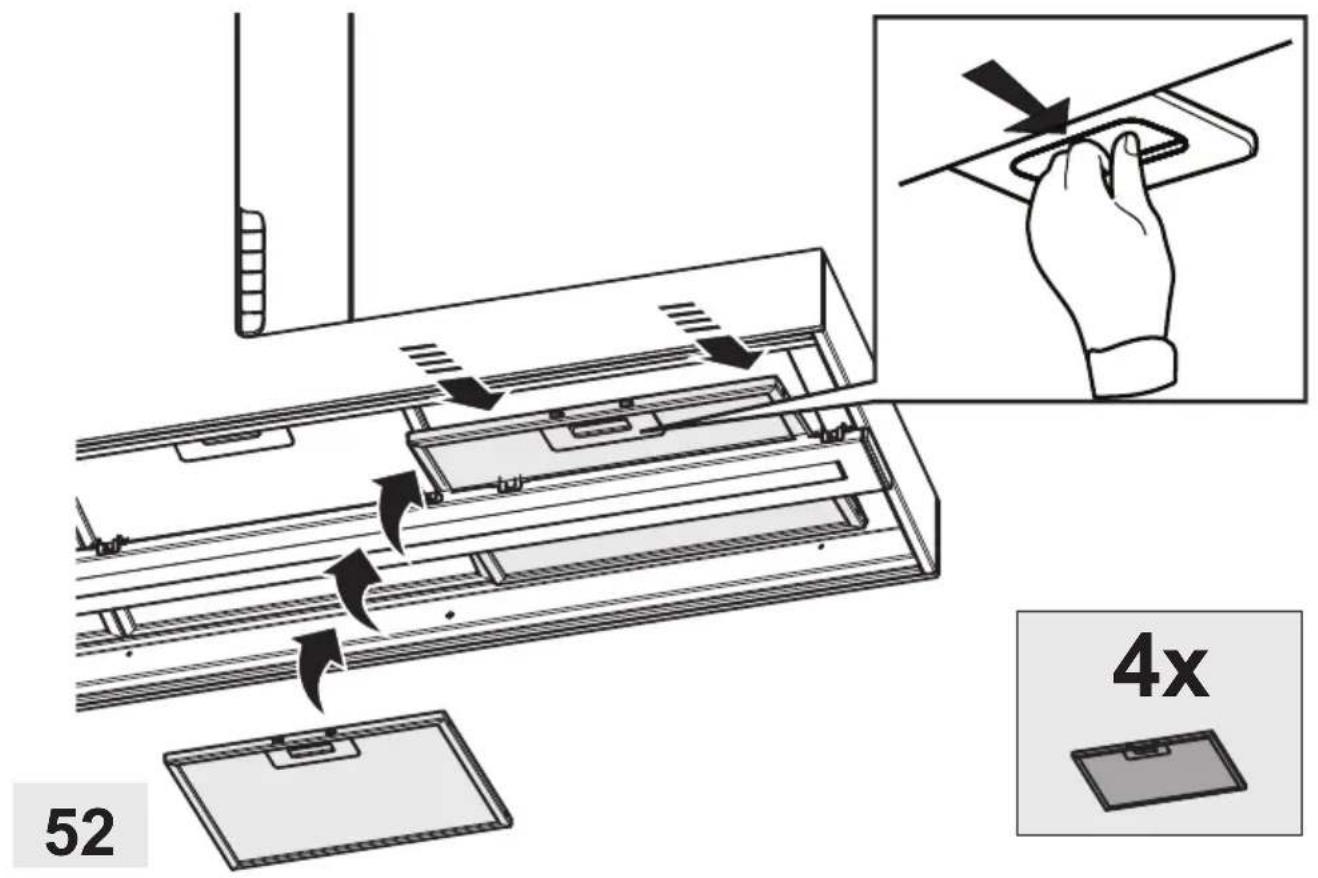
text_image
52 4x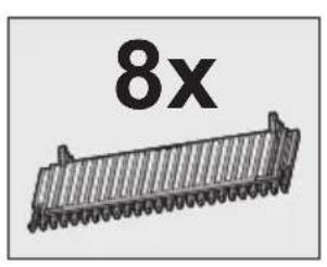
text_image
8x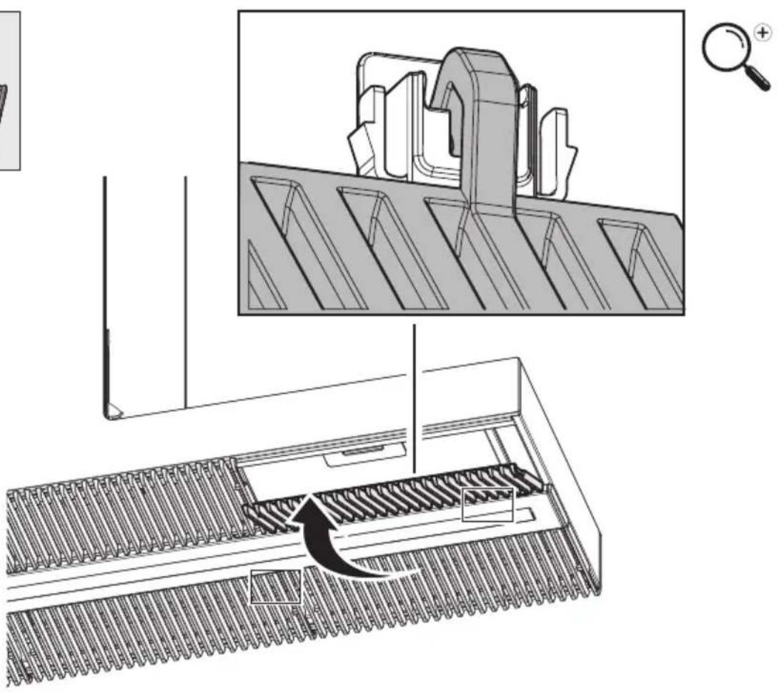
natural_image
Technical illustration of a mechanical assembly with a magnified inset showing a component being processed (no text or symbols present)LIB0157463 Ed. 08/19