GCH B 117 - Basket Gurari - Free user manual and instructions
Find the device manual for free GCH B 117 Gurari in PDF.

User questions about GCH B 117 Gurari
0 question about this device. Answer the ones you know or ask your own.
Ask a new question about this device
Download the instructions for your Basket in PDF format for free! Find your manual GCH B 117 - Gurari and take your electronic device back in hand. On this page are published all the documents necessary for the use of your device. GCH B 117 by Gurari.
USER MANUAL GCH B 117 Gurari
Manual for installation and use for model
natural_image
Technical line drawing of a rectangular industrial or mechanical component with a circular top and base, no text or symbols present.GCH B 117
PRIME N
Dear customer,
we always strive to deliver you faultless products. Should this product not be in perfect condition upon receipt, please contact us immediately.
Before you start installing and / or using this product, please read this instruction carefully and be sure to follow the instructions given. Check the delivered parts for completeness and integrity. Should, despite our efforts, any parts be defective or missing, please contact us. You will receive immediate replacement in this case.
Never use defective parts!
This cooker hood has been constructed for installation and appropriate use in private households. Incorrect installation can damage the appliance and / or your kitchen, as well as it could lead to serious injuries. Do not use parts of the cooker hood or the hood itself for purposes that are not explicitly listed in the manual. No liability is taken over for accidents or damage, due to incorrect installation, use of defective parts or incorrect use of delivered utensils.
The supplied mounting parts are not suitable for all ceilings. If you are not sure which material your ceiling consists of and whether it has sufficient load-bearing capacity, be sure to check with an expert. You may need special screws and dowels that are not included.
If you do not understand this manual or are concerned about your safety, we recommend the commissioning of an experienced installer for the assembly. Due to the weight and the dimensions of this product we recommend to carry out the installation with 2 persons in any case.
We wish you a lot of joy with your new extractor hood.
General information
Pay attention to the environmentally friendly disposal of the packaging.
Please read this manual carefully before use. It contains important information about your safety, installation, commissioning, cleaning and care of your cooker hood.
Keep the instructions in a safe place if you need to read them again or need further hints and help in use.
Please to not start a damaged device.
The device is only suitable for use in private households and not in gastronomy.
Assembly and operation may only be carried out in accordance with the instructions in this manual.
Our devices comply with the legal requirements for electrical household appliances and may therefore only be repaired by authorized personnel. Besides the dangers involved by inappropriate treatment, we strongly point out, that improper intervention void the warranty.
Delivery content
- hood body incl. LED lights / motor / control / grease filter
- Outlet Reducer ø150mm / ø120mm
- Mounting material
- Operation manual
Technical specifications
power
- power consumption in watts 206W
- Of which lighting (LED) 2x 3W
- Voltage in volts 220-240V
- Fan volume max. 1000m^3/h
Dimensions
- Height in cm 25cm
- Width in cm 60cm
- Depth in cm 30-45cm
- Exhaust outlet in mm ø150mm
- Net weight in kg approximately 7.5kg
specifications
- Built-in hood for installation in a cabinet
- Connection with safety plug
- 3-level control
- LED lighting (2x 3W)
- grease filter (dishwasher-safe)
- Suitable for recirculation and exhaust air
safety instructions
power supply
The connection is made via a fixed cable with earthing contact plug.
In the case of a required permanent connection, the hood may only be installed by an electrician, registered at the responsible electricity supply authority.
On the installation side, a disconnecting device (this includes fuses, contactors and circuit breaker acc. VDE 0730, §7, Part 1) has to be used.
Use in exhaust mode
In order to ensure optimal operation with exhaust air, we recommend implementation of the following activities
- Short, straight tube guide
- As few pipe bends as possible
- Laying the pipes in flat bends and avoiding sharp angles
- The largest possible pipe diameter
Failure to comply with these points may result in drastic loss of performance and possible raise of operating noise. This is not to be regarded as a malfunction of the device.
In addition, it is in any case inadmissible to blow the exhaust air in otherwise used chimneys or other kinds of culverts. It should only be used for the air of the cooker hood.
If the exhaust air is discharged into a non-operational chimney, we recommend to obtain approval of the responsible chimney sweeper.
For all exhaust air ducts, the official regulations must generally be adhered to. In exhaust mode it has to be ensured, that enough air supply exists.
The joint operation of cooker hoods and stoves using open fire like gas, oil or coal stoves in the same room are restricted subject to country regulations. We recommend the advice and approval of the district chimney sweeper or the local building authority.
minimum distances
Distance to an electric hob
From the electric cooking area to the lower edge of the hood a minimum distance of 600mm must be maintained.
Distance to the gas hob
Between gas hobs (upper edge of pot carrier) and lower edge of the hood a minimum distance of 700mm should comply.
Other notes
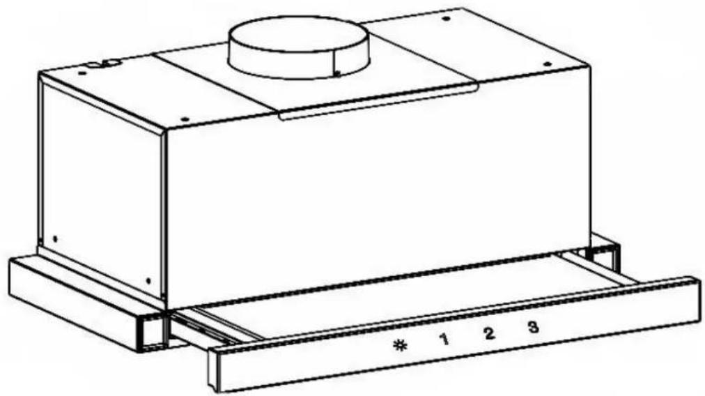
text_image
Diagram illustrating airflow or ventilation in a building facade with labeled height H and directional arrows indicating movement.Please take care, that hotplates in operation are always covered, so the device will not be damaged by excessive heat.
When deep-frying under an extractor hood, the appliance used for frying has to be supervised at all time during operation.
Oils contained in deep fryers may self-ignite due to overheating. Using old and dirty oil can lead to this even more easily.
We point out that overheating can cause a fire. Furthermore, we point out expressly that flambé under the hood is not allowed.
For all work on the cooker hood, even when changing the bulb, the hood has to be de-energized (turn off circuit breaker or remove the screw fuse from the socket). It is also important to follow the filter change and cleaning intervals.
If ignored, there is an acute fire hazard due to grease deposits!
Energy-saving tips
Preparation, warming and keeping food warm should always be done in pots or pans with closed lids.
The appliance should be switched off immediately after cooking or, if available, the time-delayed shutdown be used.
The lighting of the appliance should be switched off after the end of cooking.
Pot sizes should be adapted to the diameter of the cooking zones used.
Use the highest motor speed of the unit only at a high concentration of cooking fumes.
To increase the efficiency of the device, regularly clean the grease filters.
Carbon filters (when used in recirculation mode) should be replaced regularly according to the manufacturer's specifications.
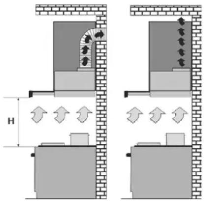
Parts of the hood
The extractor hood consists of the following parts
text_image
Technical diagram of a mechanical assembly with numbered components and directional arrows indicating motion or force vectors.- Hood body
- Exhaust outlet
- Energy cable with plug
- Slider
- Front panel
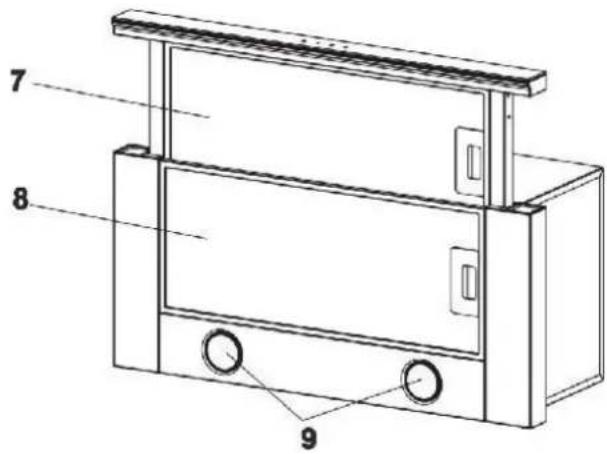
text_image
7 8 9- Touch control
- Inner grease filter
- Outer grease filter
- Light LED
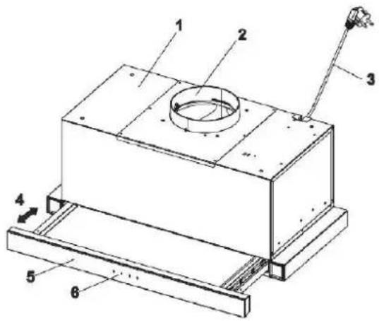
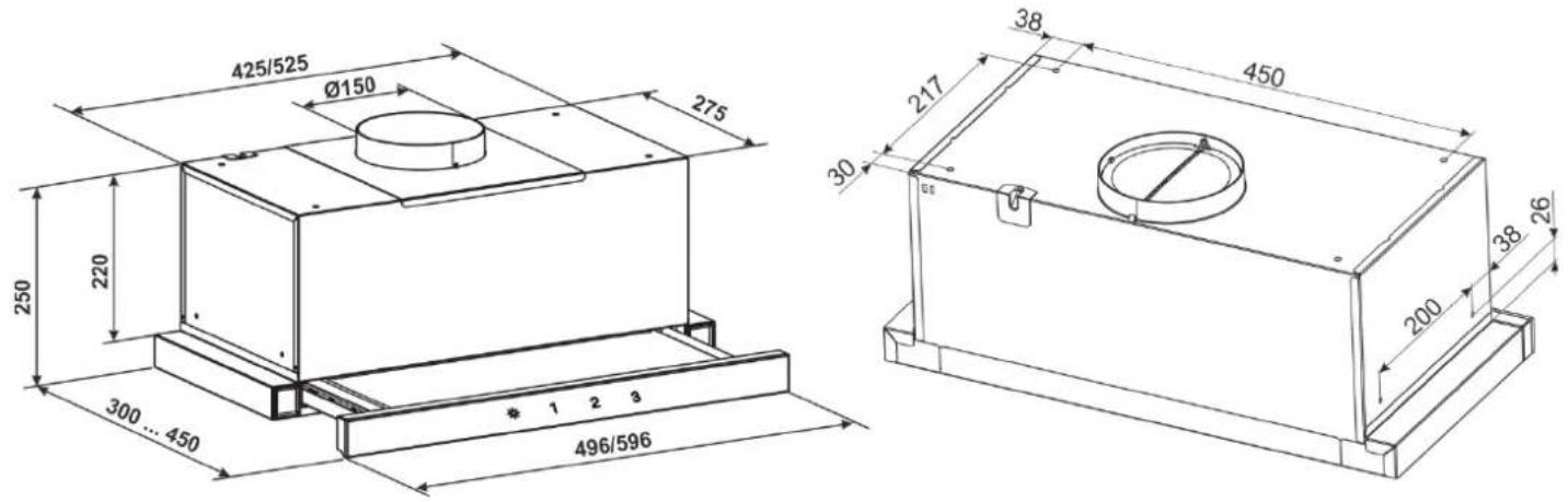
Dimension Drawings
text_image
425/525 Ø150 275 250 220 300...450 496/596 38 450 217 30 200 38 26Assembly
1. examination
Before starting the actual installation, the device should be checked. In addition to the control of externally recognizable damage, a function check has to be done. Take out the device from the packing, get rid of all packing materials and put the device with the back on the floor / table. After connecting to a power supply, the lighting as well as the function of each stage should be checked. Please take care that exhaust outlet is open through check.
2. Preparation
The hood must be installed in a cabinet. It is recommended that the cabinet is taken off the wall to ensure easier accessibility through installation. An opening has to be cut into the cabinet floor. The depth of this opening is 290mm. The width 440mm or 540mm, depending on the model. The opening is to be placed in the floor so that the lower part of the slider hood does not surmount the side walls of the cabinet after installation and the front panel is at same height as closed cupboard door.
The attachment is made to a second board, which is installed at the appropriate height. The height of this board is 204mm from the lower edge of the cabinet to the lower edge of this board. An opening for exhaust air has to be cut out from this board at the appropriate place with a 150mm diameter. It is recommended to make this opening a bit larger in order to compensate measure inaccuracies.
The hood is attached to 4 retaining holes, which are equipped with threads. The place, where these holes need to be placed and drilled have to be measured. The air discharged from the hood needs to be removed from the cabinet, regardless of whether it is used in recirculation or exhaust mode. Therefor it is necessary to cut out an exhaust vent in the cabinet ceiling at the same place as on the intermediate board. Through this, either the exhaust hose leads to the wall outlet or in recirculation mode, a pipe or hose connection leads out of the closet.
3. Installation
Have you completed the above preparations, put the plastic adapter on the air outlet of the hood, put the hood through the floor opening inside the hood and screw the hood in place.
After that create the air connection inside the cabinet for the exhaust air. If you have removed the cabinet from the wall for mounting, this must now be hung up again. As last step please connect the hood to the power supply.
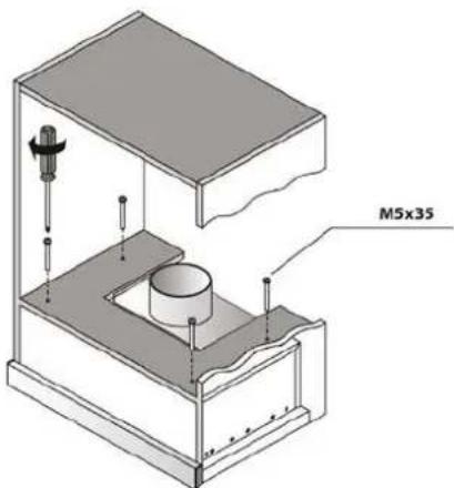
text_image
M5x35Usage
Inserting and changing the carbon filter
For recirculation mode we recommend the use of a carbon filter, which frees the cooking fumes from the smell. The carbon filter consists of two charcoal-filled cassettes, mounted left and right to the suction opening of the engine. For mounting please check picture.
To mount the carbon filter, please take the following steps:
- First remove the metal grease filters
- Place the charcoal filter on both sides of the motor in front of the suction openings
- In the middle of the filter is a receptacle and on the fan a suitable insert
- If the filter is seated correctly, you can fix it with a small twisting motion
- Then reinsert the grease filter
The matching carbon filter for this model is called GE15

natural_image
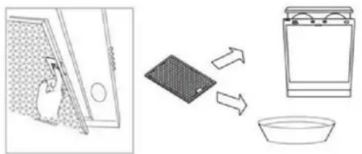
Four-panel line drawing showing a fan installation process: wire mesh, fan blade, and mechanical component (no text or symbols)Metal grease filter
The aforementioned grease filters are in front of the engine and ensure the absorption of greasy ingredients from the kitchen haze. The cleaning can be done in the dishwasher. It is recommended to do this all 14 days (at least once a month). Too long cleaning intervals lead to a blockage of the filter and thus reduced power.
Cleaning in the dishwasher
The grease filters of your hood are dishwasher safe (55 °C). However, light discoloration of the metal can arise. These have no influence on the function of the grease filter and are not considered a reason for complaint. Put the filters loosely in the dishwasher. Do not bend or pinch them. NOTE: Do not clean very dirty grease filters together with other dishes.
Cleaning by hand
If cleaned manually, first soak the grease filter extensively in hot rinse liquor, then brush well and above all, rinse well with clean water. After that drain well. Avoid use of aggressive, acidic or alkaline detergent. For very stubborn dirt you can resort to commercially available degreaser sprays.
natural_image
Illustration showing a kitchen appliance with a hand inserting a fan into a sink, alongside a washing machine (no text or symbols)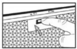
natural_image
Illustration of a hand pressing down on a textured surface with a small object, no text or symbols presentUsage

text_image
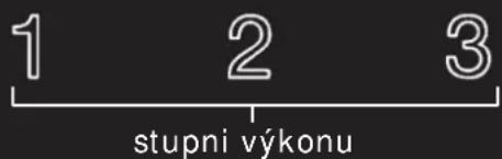
Lighting 1 2 3 Power levelsThe control takes place via a 3-stage sensor control on the front panel of the extractor hood.
1, 2 and 3 turn on the engine at the appropriate power level. Touch again the lighted power level switches the motor off again.
The field on the far left switches the LED lighting on and off again.
Timer / off timer
The extractor hood has a switchable automatic off timer (5 min). To activate this, keep the desired power level pressed for 5 seconds. After that the timer activates automatically and turns off the engine and lights after 5 minutes.
Remote control

text_image
1 2 3 4 5 + - 6The remote control controls the corresponding functions. Buttons 4 and 5, as well as button 1 turn on the hood. Button 1 turns off the hood during operation. Button 2 turns the light on or off. With button 6 one can activate the timer and set it as described above. Button 3 does not work on this unit (no automatic mode).
Cleaning and care
- De-energize the device to clean it.
- Clean the outer parts with mild soapy water. Avoid hot cleaners, brushes, or scrubbing cloths.
- Conventional glass cleaner can be used for the glass surfaces.
It is important to follow the filter changes and cleaning intervals. Failure to comply can be a fire hazard as a result of fat deposits.
Disposal of the transport packaging
The packaging protects the device against damage during transport. The packaging materials are selected to be environmentally friendly and recyclable. The return of the packaging into the material cycle saves raw materials and reduces waste. Your seller will take back the packaging.
Packing parts (e.g., foils, styrofoam) can be dangerous to children. There is danger of suffocation! Keep packaging parts out of reach of children and dispose them as soon as possible.
Disposal of the old device
Electrical and electronic devices often contain valuable materials. They also contain harmful substances that are essential to their function and safety were necessary. Disposal as residual waste can harmful to human health and the environment in case of wrong treatment. Therefore do not put your old device to residual waste. Instead, use those collection and return points established by your community or municipality for return and recovery of electrical and electronic waste.
natural_image
Symbol of a trash bin with crossed lines indicating no waste or restriction, and a solid black rectangle below (no text or labels)service
If you have any questions or problems, please contact our customer service.
MO - FR from 8:30 - 16:30
Please have the serial number and the model name of the device ready. The serial number can be found on the nameplate inside the hood.
All data subject to design changes in the context of technical development of our products.
EU Declaration of Conformity
Wir, die Firma
We, the company
declare under our sole responsibility that the following product
meets the essential requirements of the following EU-Directives:
2014/35/EC Low Voltage Directive [OJEU L96/357-374, 29.03.2014]
2014/30/EU Directive on Electromagnetic Compatibility [OJEU L96/79-106, 29.03.2014]
2011/65/EU Directive on the restriction of the use of certain hazardous substances in electrical and electronic equipment [OJEU L174/88-110, 01.07.2011]
2009/125/EC Directive for the setting of ecodesign requirements for energy-related products [OJEU L285/10-35, 31.10.2009]
Authorized person for technical documentation:
UK Declaration of Conformity
Wir, die Firma
Electrical Equipment (Safety) Regulations 2016
Electromagnetic Compatibility Regulations 2016
The Restriction of the Use of Certain Hazardous Substances in Electrical and Electronic Equipment Regulations 2012
Ecodesign for Energy-Related Products Regulations 2010
meets the essential requirements of the following UK-Regulations:
Electrical Equipment (Safety) Regulations 2016
Electromagnetic Compatibility Regulations 2016
The Restriction of the Use of Certain Hazardous Substances in Electrical and Electronic Equipment Regulations 2012
Ecodesign for Energy-Related Products Regulations 2010
Authorized person for technical documentation:
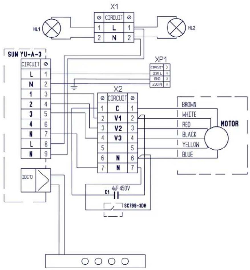
Circuit diagram for the model GCH B 117 PRIME N
text_image
X1 HL1 CIRCUIT 1 L 1 2 N 2 HL2 SUN YU-A-3 CIRCUIT L 1 N 2 1 3 2 4 3 5 4 6 N 7 L 8 N 9 X2 CIRCUIT 1 C 1 2 V1 2 3 V2 3 4 V3 4 5 5 6 N 6 7 N 7 BROWN WHITE RED BLACK YELLOW BLUE MOTOR IDC10 c1 4uF 450V SC799-3DHPossible malfunctions of the extractor hood
| Check connection to the electricity supply | Check whether the isplay is turned on | Check the lamp switch (should be turned on) | Check aluminum filter (should be leaned once every month) | Check the socket (For the power connection) | Check lamps | Check air outlet pipe (for the traction) | Check carbon filter (replacement once every 6-12 months) | |
| Extractor hood does not work |  |  |  | |||||
| The lamp does not light |  |  | ● |  | ||||
| Reduced performance of the extractor hood |  |  |  | |||||
| The extractor hood began to work louder |  |  | ||||||
| Air is poorly drawn in the recirculation mode |  |  |
Gurani
Dunstabzugshaube
natural_image
Technical line drawing of a rectangular industrial or mechanical component with a central cylindrical top and base plate (no text or symbols)GCH B 117
PRIME N
text_image
Diagram illustrating airflow or ventilation in a building facade with labeled height H and directional arrows indicating movement.Sonstige Hinweise
text_image
Technical diagram of a mechanical assembly with numbered components and directional arrows indicating motion or force vectors.natural_image
Four-panel line drawing showing a fan installation process: wire mesh, fan blade, and cylindrical component with rotation arrows (no text or symbols)natural_image
Illustration showing a hand inserting a device into a sink, with an arrow indicating direction of interaction (no text or symbols)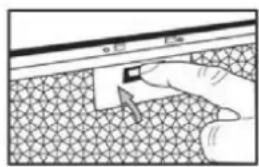
text_image
电极 电流Bedienung

natural_image
Symbol of a trash bin with crossed lines indicating no waste or restriction, and a solid black rectangle below (no text or labels)Service
EU Declaration of Conformity
Wir, die Firma
We, the company
declare under our sole responsibility that the following product
meets the essential requirements of the following EU-Directives:
2014/35/EC Low Voltage Directive [OJEU L96/357-374, 29.03.2014]
2014/30/EU Directive on Electromagnetic Compatibility [OJEU L96/79-106, 29.03.2014]
2011/65/EU Directive on the restriction of the use of certain hazardous substances in electrical and electronic equipment [OJEU L174/88-110, 01.07.2011]
2009/125/EC Directive for the setting of ecodesign requirements for energy-related products [OJEU L285/10-35, 31.10.2009]
Authorized person for technical documentation:
UK Declaration of Conformity
Wir, die Firma
We, the company
declare under our sole responsibility that the following product
Electrical Equipment (Safety) Regulations 2016
Electromagnetic Compatibility Regulations 2016
The Restriction of the Use of Certain Hazardous Substances in Electrical and Electronic Equipment Regulations 2012
Ecodesign for Energy-Related Products Regulations 2010
meets the essential requirements of the following UK-Regulations:
Electrical Equipment (Safety) Regulations 2016
Electromagnetic Compatibility Regulations 2016
The Restriction of the Use of Certain Hazardous Substances in Electrical and Electronic Equipment Regulations 2012
Ecodesign for Energy-Related Products Regulations 2010
Authorized person for technical documentation:
natural_image
Technical line drawing of a rectangular industrial or mechanical component with a cylindrical top and base, no text or symbols present.GCH B 117
PRIME N
Caro compratore,
text_image
Diagram illustrating airflow or ventilation in a building facade with labeled dimensions H and directional arrowstext_image
Technical diagram of a mechanical assembly with numbered components and directional arrows indicating motion or forcenatural_image
Four-panel line drawing showing a fan installation procedure: wire mesh, fan blade, and mechanical component (no text or symbols)text_image
Diagram illustrating kitchen cleaning steps: opening a door, lifting a plate, adding a dish, and adjusting a sink with a hand.Utilizzo

text_image
Lightin 1 2 3 Powernatural_image
Symbol of a trash bin with crossed lines indicating no waste or discharge, and a solid black rectangle below (no text or labels)Manutenzione
EU Declaration of Conformity
Wir, die Firma
We, the company
declare under our sole responsibility that the following product
meets the essential requirements of the following EU-Directives:
2014/35/EC Low Voltage Directive [OJEU L96/357-374, 29.03.2014]
2014/30/EU Directive on Electromagnetic Compatibility [OJEU L96/79-106, 29.03.2014]
2011/65/EU Directive on the restriction of the use of certain hazardous substances in electrical and electronic equipment [OJEU L174/88-110, 01.07.2011]
2009/125/EC Directive for the setting of ecodesign requirements for energy-related products [OJEU L285/10-35, 31.10.2009]
Authorized person for technical documentation:
UK Declaration of Conformity
Wir, die Firma
declare under our sole responsibility that the following product
Electrical Equipment (Safety) Regulations 2016
Electromagnetic Compatibility Regulations 2016
The Restriction of the Use of Certain Hazardous Substances in Electrical and Electronic Equipment Regulations 2012
Ecodesign for Energy-Related Products Regulations 2010
meets the essential requirements of the following UK-Regulations:
Electrical Equipment (Safety) Regulations 2016
Electromagnetic Compatibility Regulations 2016
The Restriction of the Use of Certain Hazardous Substances in Electrical and Electronic Equipment Regulations 2012
Ecodesign for Energy-Related Products Regulations 2010
Authorized person for technical documentation:
natural_image
Technical line drawing of a rectangular industrial or mechanical component with a circular top and base, no text or symbols present.GCH B 117
PRIME N
Cher client,
text_image
Diagram showing airflow or ventilation system between two building sections with labeled height H and directional arrows indicating flow direction.Commentaires
text_image
Technical diagram of a mechanical assembly with numbered components and directional arrows indicating motion or force vectors.natural_image
Four-panel line drawing showing a fan installation process: top-down view, hand holding fan blade, bottom-down view with hands adjusting panel (no text or symbols)text_image
Diagram illustrating three different cleaning and cleaning methods: door opening, grid-patterned cloth, and wash bottle.Utilisation

text_image
Eclairag 1 2 3 Niveauxnatural_image
Symbol of a trash bin with crossed lines indicating no waste or discharge, and a solid black rectangle below (no text or labels)service clientèle
EU Declaration of Conformity
Wir, die Firma
We, the company
declare under our sole responsibility that the following product
meets the essential requirements of the following EU-Directives:
2014/35/EC Low Voltage Directive [OJEU L96/357-374, 29.03.2014]
2014/30/EU Directive on Electromagnetic Compatibility [OJEU L96/79-106, 29.03.2014]
2011/65/EU Directive on the restriction of the use of certain hazardous substances in electrical and electronic equipment [OJEU L174/88-110, 01.07.2011]
2009/125/EC Directive for the setting of ecodesign requirements for energy-related products [OJEU L285/10-35, 31.10.2009]
Authorized person for technical documentation:
UK Declaration of Conformity
Wir, die Firma
declare under our sole responsibility that the following product
Electrical Equipment (Safety) Regulations 2016
Electromagnetic Compatibility Regulations 2016
The Restriction of the Use of Certain Hazardous Substances in Electrical and Electronic Equipment Regulations 2012
Ecodesign for Energy-Related Products Regulations 2010
meets the essential requirements of the following UK-Regulations:
Electrical Equipment (Safety) Regulations 2016
Electromagnetic Compatibility Regulations 2016
The Restriction of the Use of Certain Hazardous Substances in Electrical and Electronic Equipment Regulations 2012
Ecodesign for Energy-Related Products Regulations 2010
Authorized person for technical documentation:
natural_image
Technical line drawing of a rectangular industrial or mechanical housing with a circular top component and mounting base (no text or symbols)GCH B 117
PRIME N
Vážený zákazníku,
text_image
Architectural cross-section diagram showing room layout with labeled dimensions H and wall-mounted fixturesDalší pokyny
text_image
Technical diagram of a mechanical assembly with numbered components and directional arrows indicating motion or force vectors.natural_image
Four-panel line drawing showing a fan installation process: wire mesh, hand holding fan blade, and close-up of mechanical component (no text or symbols)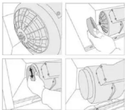
natural_image
Four-panel line drawing showing a fan installation process: wire mesh, hand holding fan blade, and close-up of mechanical component (no text or symbols)natural_image
Illustration showing a hand inserting a filter into a device, with a magnified view of the device being processed (no text or symbols present)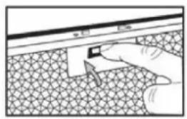
natural_image
Illustration of a hand pressing down on a textured surface with a small object, no text or symbols presentOvládání

natural_image
Symbol of a trash bin with crossed lines indicating no waste or restriction, and a solid black rectangle below (no text or labels)Údržba
EU Declaration of Conformity
Wir, die Firma
We, the company
declare under our sole responsibility that the following product
meets the essential requirements of the following EU-Directives:
2014/35/EC Low Voltage Directive [OJEU L96/357-374, 29.03.2014]
2014/30/EU Directive on Electromagnetic Compatibility [OJEU L96/79-106, 29.03.2014]
2011/65/EU Directive on the restriction of the use of certain hazardous substances in electrical and electronic equipment [OJEU L174/88-110, 01.07.2011]
2009/125/EC Directive for the setting of ecodesign requirements for energy-related products [OJEU L285/10-35, 31.10.2009]
Authorized person for technical documentation:
UK Declaration of Conformity
Wir, die Firma
We, the company
declare under our sole responsibility that the following product
Electrical Equipment (Safety) Regulations 2016
Electromagnetic Compatibility Regulations 2016
The Restriction of the Use of Certain Hazardous Substances in Electrical and Electronic Equipment Regulations 2012
Ecodesign for Energy-Related Products Regulations 2010
meets the essential requirements of the following UK-Regulations:
Electrical Equipment (Safety) Regulations 2016
Electromagnetic Compatibility Regulations 2016
The Restriction of the Use of Certain Hazardous Substances in Electrical and Electronic Equipment Regulations 2012
Ecodesign for Energy-Related Products Regulations 2010
Authorized person for technical documentation: