
JGCK424PS - Cooker JENN-AIR - Free user manual and instructions
Find the device manual for free JGCK424PS JENN-AIR in PDF.

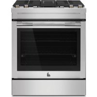
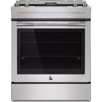
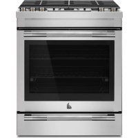
| Product Type | Built-in gas cooktop |
| Brand | Jenn-Air |
| Model | JGCK424PS |
| Number of burners | 5 (including 1 dual-flame burner) |
| Cutout dimensions (W x D) | 49,0–49,3 cm x 59,7–60,0 cm |
| Required countertop depth | 63.0 cm minimum |
| Estimated weight | 25 kg |
| Electrical supply | 120 V AC, 60 Hz, 15 A (dedicated circuit) |
| Gas supply | Natural gas or propane (convertible) |
| Natural gas pressure | 6 to 14 inches of water column |
| Propane gas pressure | 11 to 14 inches of water column |
| Ignition | Electric spark ignition; manual ignition possible during power outage |
| Materials | Stainless steel (standard finish); vitreous enamel on some models |
| Main functions | Gas burners with continuous flame adjustment |
| Cleaning | Mild cleaner and cloth; do not use abrasive products on stainless steel |
| Safety | Gas leak detection; manual shut-off valve; warning against flammable materials |
| Included parts | Grilles, burner caps, regulator, mounting brackets, gas adapters |
| Repairability | User-replaceable injectors (conversion); other repairs by qualified technician |
| Manual pages | 32 pages |
| Available languages | French, English (free download) |
Frequently Asked Questions - JGCK424PS JENN-AIR
User questions about JGCK424PS JENN-AIR
0 question about this device. Answer the ones you know or ask your own.
Ask a new question about this device
Download the instructions for your Cooker in PDF format for free! Find your manual JGCK424PS - JENN-AIR and take your electronic device back in hand. On this page are published all the documents necessary for the use of your device. JGCK424PS by JENN-AIR.
USER MANUAL JGCK424PS JENN-AIR
GAS BUILT-IN COOKTOP OWNER'S MANUAL MANUEL DU PROPRIÉTAIRE DE LA TABLE DE CUISSON À GAZ ENCASTRÉE
Table of Contents/Table des matières
COOKTOP SAFETY 2
Cooktop Safety 2
COOKTOP MAINTENANCE AND CARE 4
General Cleaning....4
INSTALLATION INSTRUCTIONS 5
REQUIREMENTS......5
Tools and Parts 5
Location Requirements 5
Electrical Requirements 6
Gas Supply Requirements 7
INSTALLATION 8
Prepare Cooktop for Installation 8
Install Cooktop 8
Make Gas Connection 9
Complete Installation 11
GAS CONVERSIONS.... 11
Low Flame Height Adjustment 13
Moving the Cooktop 14
SÉCURITÉ DE LA TABLE DE CUISSON.... 15
Installer: Leave installation instructions with the homeowner.
Homeowner: Keep installation instructions for future reference.
IMPORTANT :
Your safety and the safety of others are very important.
We have provided many important safety messages in this manual and on your appliance. Always read and obey all safety messages.

This is the safety alert symbol.
This symbol alerts you to potential hazards that can kill or hurt you and others.
All safety messages will follow the safety alert symbol and either the word "DANGER" or "WARNING." These words mean:
DANGER
WARNING
You can be killed or seriously injured if you don't immediately follow instructions.
You can be killed or seriously injured if you don't follow instructions.
All safety messages will tell you what the potential hazard is, tell you how to reduce the chance of injury, and tell you what can happen if the instructions are not followed.
WARNING: If the information in these instructions is not followed exactly, a fire or explosion may result causing property damage, personal injury or death.
- Do not store gasoline or other flammable vapors and liquids in the vicinity of this or other appliance.
-
WHAT TO DO IF YOU SMELL GAS
-
Do not try to light any appliance.
- Do not touch any electrical switch.
- Do not use any phone in your building.
- Immediately call your gas supplier from a neighbor's phone. Follow the gas suppliers instructions.
- If you cannot reach your gas supplier, call the fire department.
- Installation and service must be performed by a qualified installer, service agency or the gas supplier.
WARNING: Gas leaks cannot always be detected by smell.
Gas suppliers recommend that you use a gas detector approved by UL or CSA.
For more information, contact your gas supplier.
If a gas leak is detected, follow the "What to do if you smell gas" instructions.

WARNING:
Never Operate the Top Surface Cooking Section of this Appliance Unattended
- Failure to follow this warning statement could result in fire, explosion, or burn hazard that could cause property damage, personal injury, or death.
- If a fire should occur, keep away from the appliance and immediately call your fire department.
DO NOT ATTEMPT TO EXTINGUISH AN OIL/GREASE FIRE WITH WATER.
IMPORTANT: Do not install a ventilation system that blows air downward toward this gas cooking appliance. This type of ventilation system may cause ignition and combustion problems with this gas cooking appliance resulting in personal injury or unintended operation.
In the State of Massachusetts, the following installation instructions apply:
■ Installation and repairs must be performed by a qualified or licensed contractor, plumber, or gas fitter qualified or licensed by the State of Massachusetts.
■ Acceptable Shut-off Devices: Gas Cocks and Ball Valves installed for use shall be listed.
■ A flexible gas connector, when used, must not exceed 4 feet (121.9 cm).
IMPORTANT SAFETY INSTRUCTIONS
WARNING: To reduce the risk of fire, electrical shock, injury to persons, or damage when using the cooktop, follow basic precautions, including the following:

WARNING
NEVER use this appliance as a space heater to heat or warm the room. Doing so may result in carbon monoxide poisoning and overheating of the cooktop.
■ WARNING: Danger of fire: Do not store items on the cooking surfaces. Never leave anything on the surface when unattended and not in use. Never place flammable plastic items on or near the surface.
■ CAUTION: Do not store items of interest to children in cabinets above the cooktop – children climbing on the cooktop to reach items could be seriously injured.
■ Do Not Leave Children Alone - Children should not be left alone or unattended in area where appliance is in use. They should never be allowed to sit or stand on any part of the appliance.
■ Wear Proper Apparel – Loose-fitting or hanging garments should never be worn while using the appliance.
■ User Servicing – Do not repair or replace any part of the appliance unless specifically recommended in the manual. All other servicing should be referred to a qualified technician.
■ Do Not Use Water on Grease Fires – Smother fire or flame or use dry chemical or foam-type extinguisher.
■ Use Only Dry Potholders – Moist or damp potholders on hot surfaces may result in burns from steam. Do not let potholder touch hot surface units. Do not use a towel or other bulky cloth.
■ Never Leave Surface Units Unattended at High Heat Settings – Boilover causes smoking and greasy spillovers that may ignite.
■ Glazed Cooking Utensils – Only certain types of glass, glass/ceramic, ceramic, earthenware, or other glazed utensils are suitable for range-top service without breaking due to the sudden change in temperature.
■ Utensil Handles Should Be Turned Inward and Not Extend Over Adjacent Surface Units – To reduce the risk of burns, ignition of flammable materials, and spillage due to unintentional contact with the utensil, the handle of a utensil should be positioned so that it is turned inward, and does not extend over adjacent surface units.
■ Do not use replacement parts that have not been recommended by the manufacturer (e.g. parts made at home using a 3D printer).
- Clean Cooktop With Caution – If a wet sponge or cloth is used to wipe spills on a hot cooking area, be careful to avoid steam burn. Some cleaners can produce noxious fumes if applied to a hot surface.
■ Do Not Heat Unopened Food Containers – Build-up of pressure may cause container to burst and result in injury.
■ Proper Installation - The appliance, when installed, must be electrically grounded in accordance with local codes, or in the absence of local codes, with the National Electrical Code, ANSI/NFPA 70 or the Canadian Electrical Code, CSA C22.1. In Canada, the appliance must be electrically grounded in accordance with Canadian Electrical Code. Be sure your appliance is properly installed and grounded by a qualified technician.
This cooktop is equipped with a three-prong grounding plug for your protection against shock hazard and should be plugged directly into a properly grounded receptacle. Do not cut or remove the grounding prong from this plug.
■ Disconnect the electrical supply before servicing the cooktop.
■ Injuries may result from the misuse of the cooktop such as stepping, leaning, or sitting on the top surface.
■ Maintenance – Keep cooktop area clear and free from combustible materials, gasoline, and other flammable vapors and liquids.
■ Top burner flame size should be adjusted so it does no extend beyond the edge of the cooking utensil. This instruction is based on safety considerations.
For units with ventilating hood -
■ Clean Ventilating Hoods Frequently – Grease should not be allowed to accumulate on hood or filter.
■ When flaming foods under the hood, turn the fan on.
For smart enabled ranges and ovens
■ Remote operation – This appliance is configurable to allow remote operation at any time. Do not store any flammable materials or temperature sensitive items inside, on top or near surface units of the appliance.
SAVE THESE INSTRUCTIONS
COOKTOP MAINTENANCE AND CARE
General Cleaning
IMPORTANT: Before cleaning, make sure all controls are off at the cooktop is cool. Always follow label instructions on cleaning products.
Soap, water, and a soft cloth or sponge are suggested first, un otherwise noted.
EXTERIOR PORCELAIN ENAMEL SURFACES (on some models)
Food spills containing acids, such as vinegar and tomato, should be cleaned as soon as the cooktop, grates and caps are cool. These spills may affect the finish.
To avoid chipping, do not bang grates and caps against each other or hard surfaces such as cast iron cookware.
Do not reassemble caps on burners while wet.
Do not clean in the Self-Cleaning cycle.
Do not clean in dishwasher.
Cleaning Method:
■ Nonabrasive plastic scrubbing pad and mildly abrasive cleanser:
Clean as soon as cooktop, grates and caps are cool.
■ Gas Grate and Drip Pan Cleaner (not included):
Refer to the Quick Start Guide for contact information.
STAINLESS STEEL (on some models)
To avoid damage to stainless steel surfaces, do not use soap-filled scouring pads, abrasive cleaners, Cooktop Cleaner, steel wool pads, gritty washcloths, or abrasive paper towels.
Rub in direction of grain to avoid damaging.
Cleaning Method:
■ All-purpose cleaner:
Rinse with clean water and dry with soft, lint-free cloth.
■ Affresh® Stainless Steel Cleaner (not included): Refer to the Quick Start Guide for contact information.
BLACK STAINLESS STEEL (on some models)
To avoid damage to black stainless steel surfaces, do not use soap-filled scouring pads, abrasive or harsh cleaners, any cleaning product containing chlorine bleach, steel wool pads, gritty washcloths, or paper towels.
Cleaning Method:
■ Rinse with clean water and dry with soft, lint-free cloth.
■ Warm, soapy water - a mild detergent
COOKTOP CONTROLS
To avoid damage to the cooktop controls, do not use steel wool, abrasive cleansers, or oven cleaner.
To avoid damage, do not soak knobs.
When replacing knobs, make sure knobs are in the Off position.
Do not remove seals under knobs.
Cleaning Method:
■ Soap and water:
Pull knobs straight away from control panel to remove.
CONTROL PANEL
To avoid damage to the control panel, do not use abrasive cleaners, steel wool pads, gritty washcloths or abrasive paper towels.
Cleaning Method:
■ Glass cleaner and soft cloth or sponge: Apply glass cleaner to soft cloth or sponge, not directly on panel.
■ Affresh ^® Kitchen and Appliance Cleaner (not included): Order ess Part Number W10355010
PORCELAIN-COATED GRATES AND CAPS
Food spills containing acids, such as vinegar and tomato, should be cleaned as soon as the cooktop, grates and caps are cool.
^1 These spills may affect the finish.
To avoid chipping, do not bang grates and caps against each other or hard surfaces such as cast iron cookware.
Do not reassemble caps on burners while wet.
Cleaning Method:
■ Nonabrasive plastic scrubbing pad and mildly abrasive cleanser:
Clean as soon as cooktop, grates and caps are cool.
■ Dishwasher (grates only, not caps):
Use the most aggressive cycle.
■ Gas Grate and Drip Pan Cleaner Part Number 31617 (not included):
Refer to the Quick Start Guide for contact information.
SURFACE BURNERS
Sealed Burner models
See the "Sealed Surface Burners" section in the online Control Guide.
SIMMER PLATE (on some models)
Do not clean in dishwasher.
Cleaning Method:
■ Liquid detergent and water:
Wipe with damp cloth or sponge then rinse with clean water and wipe dry.
■ Mild-abrasive cleanser:
Rub in the direction of the grain lines with a damp cloth.
INSTALLATION INSTRUCTIONS REQUIREMENTS
Tools and Parts
Gather the required tools and parts before starting installation.
Tools Needed
■ Tape measure
■ Wrench or pliers
■ Screwdriver
■ Marker or pencil
■ 15/16" (24 mm) combination wrench
■ Pipe-joint compound resistant to Propane gas
■ Pipe wrench
■ Noncorrosive leak-detection solution
Parts Supplied
■ Gas pressure regulator
■ Burner grates
■ Burner caps
■ Clamping brackets (4)
■ 1 ^3/4 " (4.5 cm) clamping screws (2)
■ 1/4" (0.6 cm) clamping screws (2)
Gasket
■ Flare Union Adapter
■ Elbow/Union Adapter
■ Sealing Tape
For Propane/Natural Gas Conversions
Tools Needed
■ Flat-blade screwdriver
■ T20 ^® TORX ^®+ screwdriver
■ Wrench
■ 7.0 mm nut driver
■ Masking tape
Parts Supplied
■ Propane injector package
■ Conversion instructions
■ Conversion label
Parts needed
Check local codes and consult gas supplier. Check existing gas supply and electrical supply. See "Electrical Requirements" and "Gas Supply Requirements" sections.
NOTE: Be sure to purchase only Whirlpool factory-certified parts and accessories for your appliance. Your installation may require additional parts. To order, refer to the contact information referenced in your Quick Start Guide.
Location Requirements
Mobile Home Installation
The installation of this cooktop must conform to the Manufactured Home Construction and Safety Standards, Title 24 CFR, Part 3280 (formerly the Federal Standard for Mobile Home Construction and Safety; Title 24 HUD part 280); or when such standard is not applicable, the Standard for Manufactured Home Installations (Manufactured Home Sites, Communities and Setups), ANSI A225.1 - latest edition, or with local codes.
In Canada, the installation of this cooktop must conform with the current standards CAN/CSA-Z240 - latest edition, or with local codes.
IMPORTANT
■ For solid surface material installations such as Sturend Corian®, consult with solid surface manufacturer. Apply heat reflective tape such as ScotelAluminum Foil Tape #425 or #427 around the cutout so that it folds over on the top and sides.
■ Do not wrap the tape underneath the cooktop.
■ Be sure the tape extends beyond the outermost flange of the cooktop. All corners should be covered with tape.
IMPORTANT: Observe all governing codes and ordinances. Do not obstruct flow of combustion and ventilation air.
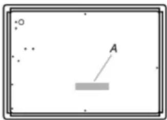
It is the installer's responsibility to comply with installation clearances specified on the model/serial/rating plate. The model/serial/rating plate is located on the underside of the cooktop base.
natural_image
Simple diagram with a rectangular frame, scattered dots, and a labeled point A pointing to a gray rectangle (no text or symbols beyond the label)A. Model/serial/rating plate
■ The cooktop should be installed in a location away from strong draft areas, such as windows, doors, and strong heating vents or fans.
■ All openings in the wall or floor where cooktop is to be installed must be sealed.
■ Cabinet opening dimensions that are shown must be used. Given dimensions are minimum clearances.
■ Grounded electrical supply is required. See the "Electrical Requirements" section. Proper gas supply connection must be available. See the "Gas Supply Requirements" section.
■ The cooktop is designed to hang from the countertop by its side or rear flanges.
■ The gas and electric supply should be located as shown in the "Cabinet Dimensions" section so that they are accessible without requiring removal of the cooktop.
■ Provide cutout in right rear corner of cutout enclosure as shown to provide clearance for gas inlet, power supply cord, and to allow the rating label to be visible.
IMPORTANT: To avoid damage, check with your builder or cabinet supplier to make sure that the materials used will not discolor, delaminate or sustain other damage.
Cabinet Dimensions
IMPORTANT: If installing a range hood or microwave hood combination above the cooktop, follow the range hood or microwave hood combination installation instructions for dimensional clearances above the cooktop surface.

A. 24" (61.0 cm) minimum
B. Combustible area above countertop (shown by dashed box above)
C. 30" (76.2 cm) minimum clearance between top of cooktop platform and bottom of uncovered wood or metal cabinet (24" [61 cm] minimum clearance if bottom of wood or metal cabinet is covered by not less than 1/4" [6.4 mm] flame retardant millboard covered with not less than No. 28 MSG sheet steel, 0.015" [0.04 mm] stainless steel, or 0.024" [0.06 mm] aluminum or 0.020" [0.05 mm] copper)
D. 13" (33 cm) recommended upper cabinet depth
E. 2 1/2" (6.35 cm)
F. 19 ^5/16 " (49.0 cm) minimum, 19 ^8/8 " (49.3 cm) maximum
G. 18" (45.7 cm) minimum clearance from upper cabinet to countertop within minimum horizontal clearances to cooktop
H. Grounded outlet: locate within 12" (30.5 cm) of right rear corner of cutout
- 23 12 " (59.7 cm) minimum, 2 38 " (60.0 cm) maximum
J. 5" (12.7 cm) minimum distance to nearest left and right side combustible surface
K. 3" (7.62 cm) minimum distance to rear combustible surface
L. Gas line opening - wall: anywhere 5" (12.7 cm) below underside of countertop. Cabinet floor: anywhere within 6" (15.2 cm) of rear wall is recommended
M. 24 ^13/16 " (63.0 cm) minimum countertop depth is required
NOTE: After making the countertop cutout, some installations may require notching down the base cabinet side walls to clear the cooktop base. To avoid this modification, use a base cabinet with sidewalls wider than the cutout.
If cabinet has a drawer, a 4" (10.2 cm) depth clearance from the countertop to the top of the drawer (or other obstruction) in base cabinet is required. The drawer depth may need to be shortened to avoid interfering with the regulator.
Electrical Requirements
General Information
This appliance must be supplied with the proper voltage and frequency and connected to an individual, properly grounded branch circuit, protected by a circuit breaker or fuse having amperage as noted on the rating plate. We recommend you have the electrical wiring and hookup of your cooktop connected by a qualified electrician.
After installation, have the electrician show you where your main cooktop disconnect is located. Check with your local utilities for electrical codes which apply in your area. Failure to wire your cooktop according to governing codes could result in a hazardous condition.
If there are no codes, your cooktop must be wired and fused to meet the requirements of the National Electrical Code, ANSI/NFPA No. 70 - Latest edition.
You can get a copy by writing:
National Fire Protection Association
Battery march Park
Quincy. MA 02269
In Canada your cooktop must be wired and fused to meet the requirements of the Canadian Electrical Code, CSA C22.1-02.
Be sure the installation of this product in a mobile home conforms with the Manufactured Home Construction and Safety Standard, Title 24 CFR, Part 3280.
If this standard does not apply, you must follow the standard for Manufactured Home Installations, ANSI A225.1 and Manufactured Home Installations, Sites and Communities and ANSI/NFPA 501A or with local codes.
You can get a copy of the Federal Standard by Writing:
Office of Mobile Home Standard HUD Building
451 7th Street, S. W.
Washington, D.C. 24010
Electrical Connection
An adequate electrical supply and outlet must be used to operate the electrical parts of your cooktop.
WARNING

Electrical Shock Hazard
Plug into a grounded 3 prong outlet.
Do not remove ground prong.
Do not use an adapter.
Do not use an extension cord.
Failure to follow these instructions can result in death, fire, or electrical shock.
IMPORTANT: For personal safety, this appliance must be properly grounded.
The power cord of this appliance is equipped with a 3-prong (grounding) plug which must be used with a properly grounded 3-hole outlet with a standard 120 V, 60 cycle AC household current. If you do not have a 3-hole grounded outlet, have a qualified electrician change your old one. A grounding adaptor be needed to convert the old one until the outlet can be repla. This method is only temporary, and a qualified electrician should test it to be sure it meets requirements.
Electrical Requirements
Do not under any circumstances cut or remove grounding prong from the cooktop cord.
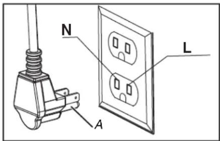
A. Grounding prong
Gas Supply Requirements
WARNING
Explosion Hazard
Use a new CSA International approved gas supply line. Install a shut-off valve.
Securely tighten all gas connections.
If connected to propane, have a qualified person make sure gas pressure does not exceed 14" (36 cm) water column.
Examples of a qualified person include: licensed heating personnel, authorized gas company personnel, and authorized service personnel.
Failure to do so can result in death, explosion, or fire.
A QUALIFIED SERVICE MAN OR GAS APPLIANCE INSTALLER MUST MAKE THE GAS SUPPLY CONNECTION.
Observe all governing codes and ordinances.
IMPORTANT: This installation must conform with all local codes and ordinances. In the absence of local codes, installation must conform with the National Fuel Gas Codes ANSI Z223.1/NFPA 5 or, in Canada, the Natural Gas and Propane Installation Code, CSA B149.1 - latest edition.
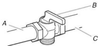
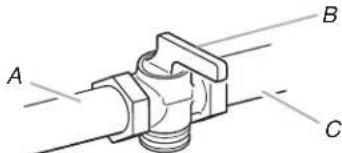
Leak testing of the appliance shall be conducted by the installer according to the instructions given. You must install the supplied connection parts seen here in this configuration to the main gas manifold on the appliance. Issues arising from a failure to do so will not be covered by warranty.
Do not install the pressure regulator backwards as the gas will not flow correctly. Check that the arrow on the back points in the direction of gas flow.
Parts required for connection from gas supply to regulator are the responsibility of the installer/owner.
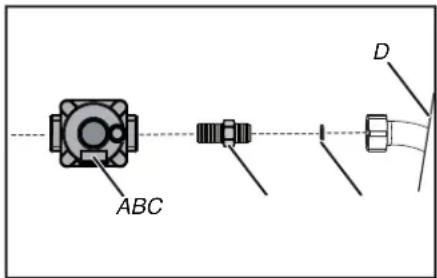
A. Appliance pressure regulator
B. Flare union adaptor
C. Gasket
D. Appliance
NOTE: Use TEFLON® tape rated for gas applications at all threaded connections. Do not overtighten the connection at the manifold or you could damage the gasket causing a leak.
IMPORTANT: If the line pressure supplying the appliance pressure regulator exceeds 14 inches W.C. (any gas), an external regulator must be installed in the gas line ahead of the appliance regulator to reduce the pressure to prevent malfunction and damage to the appliance.
Important Notes for Gas Connection
The appliance and its individual gas shutoff valve must be disconnected from the gas supply piping system during any pressure testing of that system at test pressures in excess of 1/2 psi (3.5 kPa).
The appliance must be isolated from the gas supply piping system by closing its individual manual shut-off valve during any pressure testing of the gas supply piping system at test pressures equal to or less than 1/2 psi (3.5 kPa).
All supply piping, except as noted, should use common National Pipe Thread (NPT). For all pipe connections use an approved pipe joint compound resistant to the action of propane gas.
This appliance is designed for use with natural gas or propane gas. The gas pressure regulator is supplied with this appliance. It must be installed in the gas way ahead of the manifold entrance. It is pre-set for use with natural gas. To use it with different gas it must be converted, as described in the Gas conversion paragraph.
If at any time the appliance is to be used with a different type of gas, all the conversion adjustments must be made by a qualified technician before attempting to operate the cooktop on that gas.
The gas should be supplied to the appliances pressure regulator, at line pressure between 6" (15.24 cm) and 14" (35.56 cm) of water column for natural gas, and between 11" (27.94 cm) and 14" (35.56 cm) of water column for propane gas.
| 4GAS REQUIREMENTS | |
| NATURAL GAS WC | |
| Manifold Pressure 5" (12.5 mb) | |
| Minimum Line Pressure 6" (15 mb) | |
| Maximum Line Pressure 14" | (34.9 mb), .5 psi (3.5 kPa) |
| PROPANE GAS WC | |
| Manifold Pressure 10" (25 mb) | |
| Minimum Line Pressure 11" (27.4 mb) | |
| Maximum Line Pressure 14" (34.9 mb), .5 psi (3.5 kPa) | |
IMPORTANT:
■ NEVER REUSE OLD CONNECTORS WHEN INSTALLING THIS COOKTOP.
To reduce the likelihood of gas leaks, apply TEFLtOPE or a thread compound approved for use with propane or natural gases to all threaded connections.
Apply a non-corrosive leak detection fluid to all joints and fittings in the gas connection between the supply line shut-off valve and the cooktop inlet.
Check for leaks, Bubbles appearing around fittings and connections will indicate a leak.
If a leak appears, turn off supply line gas shut-off valve, tighten connections, turn on the supply line gas shutoff valve, and retest for leaks.
Never test for gas leaks with an open flame.
■ NEVER TIGHTEN TO MORE THAN 35 ft lbs OF TORQUE.
INSTALLATION
Prepare Cooktop for Installation
WARNING
Excessive Weight Hazard
Use two or more people to move and install or uni appliance.
Failure to do so can result in back or other injury.
- Remove packaging materials and literature package from the cooktop before beginning installation.
- Remove Installation Instructions from literature pack and read them thoroughly before you begin.
Install Cooktop
Step 1:
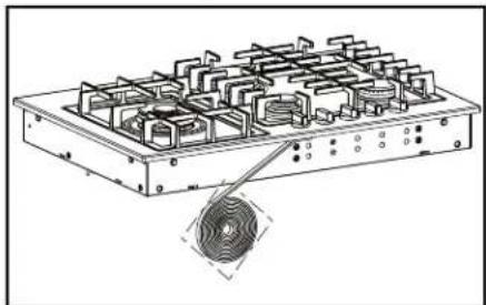
■ Before installing apply the foam tape.
A tape is provided to seal the cooktop edges to the countertop. Apply tape near inner underside cooktop edge. Use tape around the entire cooktop perimeter.
■ Cut off excess where tape butt ends.
natural_image
Technical line drawing of a mechanical component with grid-like internal structure and a magnified circular detail (no text or symbols)Step 2:
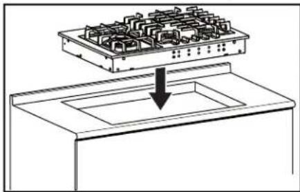
■ Insert the cooktop centered into the cutout opening.
■ Make sure the front edge of the counter top is parallel to the cooktop. Make final check that all required clearances are met.
natural_image
Diagram of a mechanical assembly with a bracket and a downward arrow indicating force or direction (no text or symbols)Step 3:
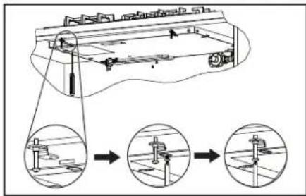
■ Four clamp brackets are provided with your unit.
■ After cooktop has been installed into the countertop, install the en brackets on the burner box as shown in figure.
■ Install the clamp brackets on the front and back of the burner box bottom (if the cabinet construction does not provide clearance for installing brackets at the burner box front back install the clamp brackets on the lateral position of burner box).
Step A: Place the clamping screws into brackets.
Step B: Attach brackets by using the attachment screws on the selected location of burner box, tighten screws just enough to hold brackets in place step C position brackets so that they are with the clamp screw in contact with the counter top bottom.
Step C: Tighten attachment screws securely.
Step D: Check that the front edge of the cooktop is parallel to the front edge of the countertop tighten the screw clamping against the countertop.
stallNOTE: Do not over tighten.
Make Gas Connection
WARNING
Explosion Hazard
Use a new CSA International approved gas supply line. Install a shut-off valve.
Securely tighten all gas connections.
If connected to propane, have a qualified person make sure gas pressure does not exceed 14" (36 cm) water column.
Examples of a qualified person include: licensed heating personnel, authorized gas company personnel, and authorized service personnel.
Failure to do so can result in death, explosion, or fire.
- Thread the appliances pressure regulator with 1/2" (12.7 mm) male end connection both supplied with this appliance.
- Make the gas connection to the inlet of the pressure regulator with 1/2" (12.7 mm) male pipe threads.
- Join the pressure regulator to the entrance threads of the Gas Manifold with gasket supplied with this appliance. The regulator is marked with a directional arrow indicating correct direction of gas flow. Ensure the appliance regulator is installed with the arrow pointing toward the gas manifold entrance and make sure the top of the regulator is facing towards the cabinet front, easily accessible through the cabinet doors.
- Connect a manual shut-off valve to the gas supply in an accessible location for turning on or shutting off gas to the appliance.
- Install a coupling between the regulator and the shutoff valve to complete the connection.
- Assure all pipe joint connections are gas tight.
- Check alignment of valves after connecting the cooktop to the gas supply to be sure the manifold pipe has not been moved.
- A misalignment could cause the valve knob stem to rub on the control panel, resulting in a gas leak at the valve.
If an oven is to be installed below this appliance connect gas supply line as shown in figure consider the below cabinet clearance.
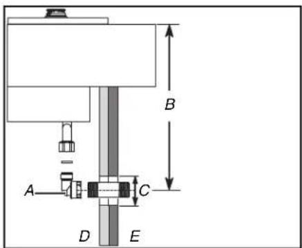
A. 90° Street Elbow
B. 4 ^13/_16 " (12.2 cm)
C. 1 15 " (3 cm)
D. Cabinet sides
E. Cabinet sides
NOTE: Illustrative Gas Supply Piping (No Other Appliance Below Cooktop)
A. Burner box (rear of appliance)
B. Gasket
C. Flare union adaptor
D. Appliance pressure regulator
E. All pipe joints 1/2" (12.7 mm) NPT
F. Manifold shutoff valves
G. Gas
IMPORTANT: For alternative piping methods to connect the appliance to the gas supply, a trained service person or gas appliance installer must make the gas supply connection.
Leak testing of the appliance shall be conducted by the Installer according to the Instructions given.
Unless prohibited by local codes or ordinances, a new A.G.A.
- Certified, flexible metal appliance connector may be used to connect this appliance to its gas supply.
The connector must have an internal diameter not less than nominal 1/2" (12.7 mm) NPT pipe and be no more than 5 ft in length. A 1/2" (12.7 mm) NPT x 1/2" (12.7 mm) flare union adapter is required at each end of the flexible connector.
If a flexible connector is used assure that both the appliance pressure regulator and manual shut-off valve are joined solidly to other permanent hard piping (either gas supply or the appliance manifold) so as to be physically stationary. See figure.
IMPORTANT: Do not attempt to attach the flexible connector directly to an external pipe thread.
Connection requires flare union adapters.
For Massachusetts Installations:
- Shut-off valve must be a "T" handle gas cock.
- Flexible gas connector must not be longer than 36" (91.44 cm).
- Not approved for installation in a bedroom or a bathroom unless unit is direct vent.
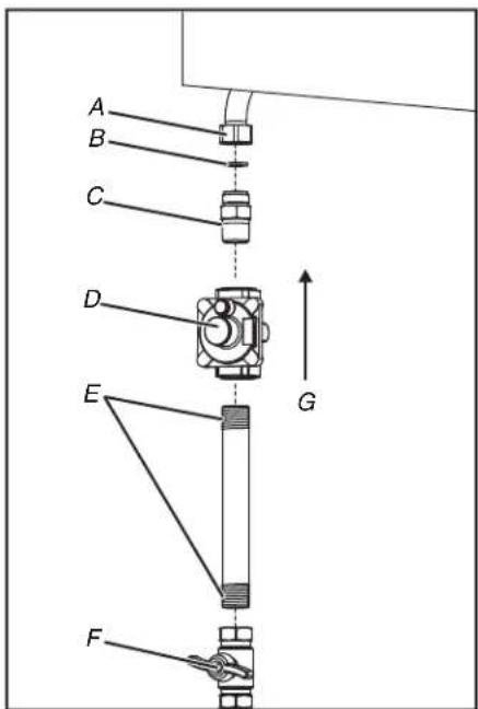
No Appliance Mounted Below This Cooktop
A. Manifold entrance
B. Gasket
C. Flare union adaptor
D. Appliance pressure regulator, supplied (observe directionality of gas flow)
E. Flare union adaptor
F. Flexible appliance connector 5 ft maximum (1.52 m) maximum
G. Flare union adaptor
H. Gas shut-off valve
I. 1/2" (12.7 mm) NPT pipe (stationary supply pipe)
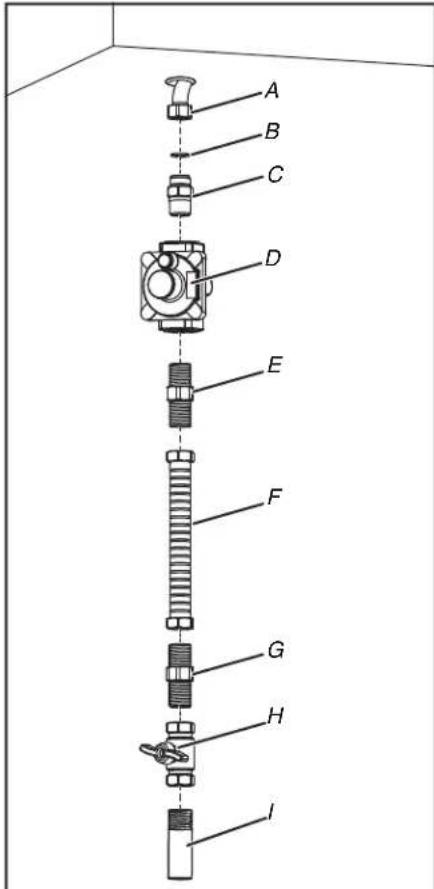
Wall Oven Mounted In Cabinetry Below This Cooktop
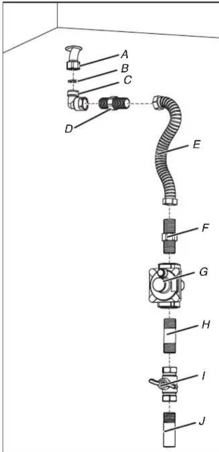
A. Manifold entrance
B. Gasket
C. 1/2" (12.7 mm) NPT pipe nipple elbow
D. Flare union adaptor
E. Flexible appliance connector 5 ft maximum (1.52 m) maximum
F. Flare union adaptor
G. Appliance pressure regulator, supplied (observe directionality of gas flow)
H. 1/2" (12.7 mm) NPT pipe nipple
I. Gas shut-off valve
J. 1/2" (12.7 mm) NPT pipe (stationary supply pipe)
Complete Installation
Pressure Testing
The appliance must be isolated from the gas supply piping system by closing its individual manual shut-off valve during any pressure testing of the gas supply piping system at test pressures equal to or less than 1/2 PSIG (3.5 kPa).
This appliance, as well as its individual shut-off valve, must be disconnected from the gas supply piping system during any pressure testing of the system at test pressures in excess of 1/2 PSIG (3.5 kPa).
When checking appliance regulator function, make certain pressure of natural gas supply is between 6" (15.24 cm) and 14" (35.56 cm) of water column or, if converted for propane gas, between 11" (27.94 cm) and 14" (35.56).
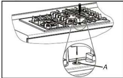
NOTE: The pressure testing should be performed by means of injector thread zone.
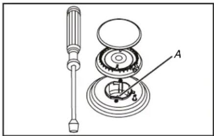
natural_image
Technical line drawing of a screwdriver and mechanical assembly with labeled component A (no text or symbols beyond label)A. Gas test inlet Thread
Pressure Test Method
■ Remove grate and burner cap.
■ Remove aluminum gas spreader.
■ Temporarily remove the injectors
■ Connect the pressure Test instrument into injector holder thread zone (M6x0,75)
■ Check if the cooktop has the correct pressure
- Fix the injector removed for testing and replace the parts in right position.
GAS CONVERSIONS
IMPORTANT: Gas conversions from Natural gas to propane must be done by a qualified installer. Before proceeding with conversion, shut off the gas supply to the appliance prior to disconnecting the electrical power.

WARNING:
This conversion kit shall be installed by a qualified service agency in accordance with the manufacturer's instructions and all applicable codes and requirement the authority having jurisdiction. If the information in these instructions is not followed exactly, a fire, an explosion or production of carbon monoxide may res causing property damage, personal injury or loss of The qualified service agency is responsible for the p installation of this kit. The installation is not proper complete until the operation of the converted appliance checked as specified in the manufacturer's instruction supplied with the kit.
of
WARNING
Explosion Hazard
Use a new CSA International approved gas supply line. Install a shut-off valve.
Securely tighten all gas connections.
thelf connected to propane, have a qualified person make sure gas pressure does not exceed 14" (36 cm) water column.
Examples of a qualified person include: licensed heating personnel, authorized gas company personnel, and authorized service personnel.
Failure to do so can result in death, explosion, or fire.
Converting Appliance for Use with Propane Gas
IMPORTANT : Conversion is to be performed in accordance with the manufacturer's instructions and all codes and requirements of the authority having jurisdiction. Failure to follow instructions could result in serious injury or property damage.
The qualified agency performing this work assumes responsibility for this conversion.
IMPORTANT: Before proceeding with the conversion, shut off the gas supply to the appliance prior to disconnecting the electrical power.
If this appliance should be converted for use with propane gas, each of the following modification must be performed:
Gas conversion label (aluminium) to be placed on the back of the appliance, near the data plate, after conversion has been carried out.
Replace injector on (one ring flame burners)
- Turn manual shut-off valve to the closed position.
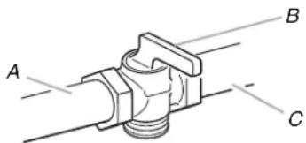
A. To cooktop
B. Shut-off valve (closed position)
C. Gas supply line
-
Unplug cooktop or disconnect power.
-
Remove the grates and burner cups.
-
Remove aluminum gas spreader.
-
Loosen injector by turning 9-32" (7 mm) nut driver counter clockwise.
-
Install the injectors supplied with this appliances in the appropriate burner. The injectors have small number stamped on the side, this number codes the orifice diameter and its correct burner location (see the Injectors Position table).
- Turn clockwise to tighten (tighten to a torque of 15 to 20 inch-lbs).
-
Replace all parts following the reverse order.
-
Save the injectors removed from the appliance for future use.
natural_image
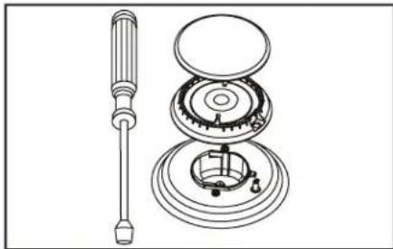
Technical line drawing of a mechanical assembly with a screwdriver and internal components (no text or symbols)Replace injectors on (two rings flame burner)
- Turn manual shut-off valve to the closed position.
A. To cooktop
B. Shut-off valve (closed position)
C. Gas supply line
- Unplug cooktop or disconnect power.
- Remove the grates and burner cups.
- Remove aluminium gas spreader.
- Remove the three screws of simmer gas spreader (A).
- Remove the two screws of injector cover (B).
- Loosen injector (C) by turning 9-32" (7 mm) nut driver counter clockwise.
- Loosen injector (D) by turning 9-32" (7 mm) box wrench counter clockwise.
- Install the injectors supplied with this appliances in the appropriate burner. The injectors have small number stamped on the side, this number codes the orifice diameter and its correct burner location (see the Injectors Position table).
- Turn clockwise to tighten (tighten to a torque of 15 to 20 inch-lbs).
- Replace all parts following the reverse order.
- Save the injectors removed from the appliances for future use.
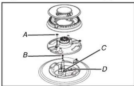
A. Screws of simmer gas spreader
B. Screws of injector cover
C. Injector
D. Injector
After injectors replacement adjust the burner flame (see Low Flame Adjustment section).
Check the appearance of each burner's flame at HI LO settings, ^2 if the flame appear too large or too small make sure that all steps were completed correctly.
Converting Appliances for Use with Natural Gas
If this appliance should be converted for use with natural gas, each of the following modifications must be performed.
- Turn manual shut-off valve to the closed position.
A. To cooktop
B. Shut-off valve (closed position)
C. Gas supply line
-
Unplug cooktop or disconnect power.
-
Replace all injectors as shown in the Converting Appliance for Use with propane gas section, observe the number stamped on the side, this number codes the orifice diameter and its correct burner location (see the Injectors Position table).
- Convert the pressure regulator on propane gas position (following the illustration of pressure regulator conversion).
- Adjust the burner flame (see Low Flame Adjustment section).
Check the appearance of each burner's flame at HI LO settings, if the flame appears too large or too small make sure that all steps were completed correctly.
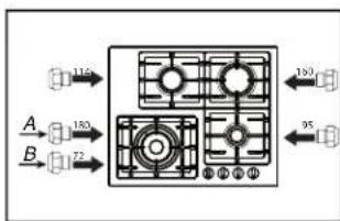
Injectors position
Natural Gas Propane Conversion
Injector Position
flowchart
graph TD
    A["Component A"] -->|115| B["Terminal 1"]
    C["Component B"] -->|180| D["Terminal 2"]
    E["Component B"] -->|72| F["Terminal 3"]
    G["Component B"] -->|183| H["Terminal 4"]
    I["Component B"] -->|95| J["Terminal 5"]
A. Main flame
B. Simmer
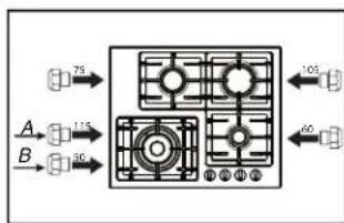
flowchart
graph TD
    A["Port 75"] --> B["Control Unit"]
    C["A"] --> D["Port 115"]
    E["B"] --> F["Port 30"]
    B --> G["Port 105"]
    F --> H["Port 60"]
A. Main flame
B. Simmer
Pressure regulator conversion
The appliances is designed for use with natural gas or propane gas. The gas pressure regulator is supplied. It must be installed in the gas way ahead of manifold entrance. It is pre-set for use with the gas supplied with the appliances. For use with different gas must be converted.
For the pressure regulator conversion following the below instructions:
■ Disconnect all electrical power, at the main circuit breaker or fuse box.
■ Shut off the gas supply to the cooktop by closing the manual shut-off valve.
■ Adjust the pressure regulator, by following the instruction (see figure).
- Unscrew the regulator cap.
2f Unscrew the plastic conversion plug from the cap turn over and screw back (wide section away from cap for propane and against cap for natural gas) see figures below.
- Replace the cap regulator.
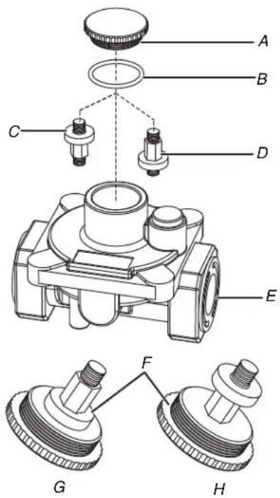
A. Cap
B. Gasket
C. Natural gas position
D. Propane gas position
E. Pressure regulator
F. Plug
G. Natural gas plug
H. Propane gas plug
NOTE:
Before replace the regulator cap.
Check the position of plug.
Suitable for the gas converted.
Low Flame Height Adjustment
Light a match and hold the flame near the burner you want to light. Wooden matches work best. Push in and turn the control knob slowly. Be sure you are turning the correct knob for the burner you are lighting.
NOTE: If the burner does not light within five seconds, turn the knob off and wait one minute before trying again.
This appliance is shipped from the factory with low and medium flame settings adjusted. If further adjustment is necessary, proceed as follows:
Adjustment for Burners with one or two rings flame:
- Light burner and set control knob for low flame.
- Remove control knob from valve stem.
- Insert a slender, thin-blade screwdriver into the recess at centre of valve stem and engage blade with slot in adjusting screw.
- Turn center stem adjusting screw to set flame size:
■ Clockwise to reduce
■ Counterclockwise to increase
- Replace control knob when adjustment is completed.
Low flame adjustment
One or two rings flame
natural_image
Technical line drawing of a mechanical component with a magnified inset showing a detail labeled 'A' (no text or symbols present)A. Valve stem
■ Counterclockwise to increase flame size
■ Clockwise to reduce flame size
Proper adjustment will produce a stable, steady blue flame of minimum size.
The final adjustment should be checked by turning knob from high to low several times without extinguishing the flame. This adjustment, at low setting, will automatically provide the proper flame size at medium setting.
After Conversion steps have been completed, check the appearance of each burner's flame at the HI and LO settings, if the flames appear too large or too small review each step to make sure it was completed correctly.
NOTE: To obtain the correct minimum setting with propane gas, turn clockwise tightening the valve fully by the thin-blade screwdriver into the recess at centre of valve stem.
Electric gas ignition
The gas burner use an electric ignition device located near each burner that by means a spark igniters ensure its surface light automatically.
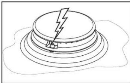
natural_image
Simple line drawing of a mechanical component with a lightning bolt and base, resting on layered circular surfaces (no text or symbols)The Burner Flames
Turn each burner on. Flames should be blue in color with no trace of yellow. The burner flames should not flutter or blow away from the burner. The inner cone of the flame should be between 1/2" (1.27 cm) and 3/4" (1.91 cm) long.
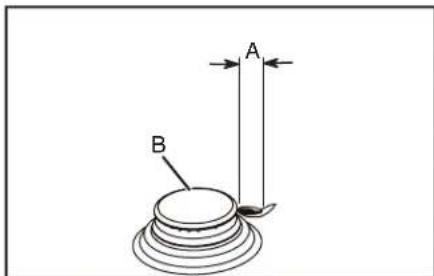
A. 1/2" (1.27 cm) to 3/4" (1.91 cm)
B. Cooktop burner
Power Failure
In case of prolonged power failure, the surface burners can be manually. Hold a lit match near a burner and push in and turn gas control knob to HI until it lights and then turn the knob to desired setting.
Moving the Cooktop
WARNING

Electrical Shock Hazard
Disconnect power before servicing.
Failure to do so can result in death or electrical shock.
WARNING
Explosion Hazard
Use a new CSA International approved gas supply line.
Install a shut-off valve.
Securely tighten all gas connections.
If connected to propane, have a qualified person make sure gas pressure does not exceed 14" (36 cm) water column.
Examples of a qualified person include: licensed heating personnel, authorized gas company personnel, and authorized service personnel.
Failure to do so can result in death, explosion, or fire.
WARNING
Excessive Weight Hazard
Use two or more people to move and install or uninstall appliance.
Failure to do so can result in back or other injury.
If removing the cooktop is necessary for cleaning or maintenance:
- Disconnect Power.
- Shut gas line off.
- Disconnect the flexible stainless steel connector.
- Uninstall clamp brackets.
- Using two or more people, place the cooktop on a covered surface.
- Complete cleaning or maintenance.
- Reinstall cooktop using the "Install Cooktop" section of your Owner's Manual.
SÉCURITÉ DE LA TABLE DE CUISSON
natural_image
Simple diagram with a rectangular frame, scattered dots, and a labeled arrow pointing to a gray rectangle (no text or symbols)National Fire Protection Association
Battery march Park
Quincy. MA 02269
Office of Mobile Home Standard HUD Building
451 7th Street, S. W.
Washington, D.C. 24010
natural_image
Technical line drawing of a mechanical component with grid-like cavities and a circular feature, no text or symbols present.Étape 2 :
natural_image
Diagram of a mechanical assembly with a top component and a downward arrow indicating force or direction (no text or symbols)Étape 3 :
Raccordement au gaz
AVERTISSEMENT
Risque d'explosion
natural_image
Technical line drawing of a screwdriver and mechanical assembly with labeled component A (no text or symbols beyond label)natural_image
Technical line drawing of a screwdriver and internal mechanical components (no text or symbols)natural_image
Technical line drawing of a computer keyboard with an inset showing a component labeled A (no text or symbols present)natural_image
Isometric line drawing of a mechanical component with a lightning bolt and base, resting on layered circular surfaces (no text or symbols)
- GAS BUILT-IN COOKTOP OWNER'S MANUAL MANUEL DU PROPRIÉTAIRE DE LA TABLE DE CUISSON À GAZ ENCASTRÉE
- Table of Contents/Table des matières
- Your safety and the safety of others are very important.
- DANGER
- WARNING
- WARNING: If the information in these instructions is not followed exactly, a fire or explosion may result causing property damage, personal injury or death.
- WARNING:
- IMPORTANT SAFETY INSTRUCTIONS
- For units with ventilating hood -
- For smart enabled ranges and ovens
- SAVE THESE INSTRUCTIONS
- COOKTOP MAINTENANCE AND CARE
- General Cleaning
- EXTERIOR PORCELAIN ENAMEL SURFACES (on some models)
- Cleaning Method:
- STAINLESS STEEL (on some models)
- BLACK STAINLESS STEEL (on some models)
- COOKTOP CONTROLS
- CONTROL PANEL
- PORCELAIN-COATED GRATES AND CAPS
- SURFACE BURNERS
- Sealed Burner models
- SIMMER PLATE (on some models)
- INSTALLATION INSTRUCTIONS REQUIREMENTS
- Tools and Parts
- Tools Needed
- Parts Supplied
- For Propane/Natural Gas Conversions
- Parts needed
- Location Requirements
- Mobile Home Installation
- IMPORTANT
- Model/serial/rating plate
- Cabinet Dimensions
- Electrical Requirements
- General Information
- Electrical Connection
- Gas Supply Requirements
- Explosion Hazard
- A QUALIFIED SERVICE MAN OR GAS APPLIANCE INSTALLER MUST MAKE THE GAS SUPPLY CONNECTION.
- Important Notes for Gas Connection
- IMPORTANT:
- ■ NEVER REUSE OLD CONNECTORS WHEN INSTALLING THIS COOKTOP.
- ■ NEVER TIGHTEN TO MORE THAN 35 ft lbs OF TORQUE.
- INSTALLATION
- Prepare Cooktop for Installation
- Install Cooktop
- Step 1:
- Step 2:
- Step 3:
- Make Gas Connection
- For Massachusetts Installations:
- Complete Installation
- Pressure Testing
- Pressure Test Method
- GAS CONVERSIONS
- Converting Appliance for Use with Propane Gas
- Replace injector on (one ring flame burners)
- Replace injectors on (two rings flame burner)
- Converting Appliances for Use with Natural Gas
- Injectors position
- Pressure regulator conversion
- NOTE:
- Low Flame Height Adjustment
- Adjustment for Burners with one or two rings flame:
- Low flame adjustment
- Electric gas ignition
- The Burner Flames
- Power Failure
- Moving the Cooktop
- SÉCURITÉ DE LA TABLE DE CUISSON
- Étape 2 :
- Étape 3 :
- Raccordement au gaz
- AVERTISSEMENT
- Risque d'explosion
Brand : JENN-AIR
Model : JGCK424PS
Category : Cooker