
JDS1450ML - Cooker JENN-AIR - Free user manual and instructions
Find the device manual for free JDS1450ML JENN-AIR in PDF.
| Product Type | Gas Range with Down-Draft Ventilation |
| Brand | JENN-AIR |
| Model | JDS1450ML |
| Dimensions (W x D x H) | 76.2 cm x 71.1 cm x 91.4 cm (30" x 28" x 36") |
| Weight | Approximately 90 kg (200 lb) |
| Electrical Supply | 240 V, 40/50 A, single-phase, 4-wire |
| Gas Supply | Natural gas (convertible to propane) |
| Number of Burners | 5 surface burners |
| Maximum Burner Power | Up to 19,000 BTU (5.6 kW) for the front left burner |
| Oven | Built-in oven with AquaLift (steam) cleaning |
| Oven Capacity | Approximately 142 L (5.0 ft³) |
| Ventilation System | Down-draft ventilation with 5" or 6" round duct |
| Cleaning Functions | AquaLift (steam self-clean), manual maintenance |
| Safety | Anti-tip bracket, gas shut-off, oven door lock |
| Finish Material | Stainless steel or metallic paint depending on model |
| Included Accessories | Oven racks, broiler pan, anti-tip bracket, gas conversion kit |
| Repairability | Replacement parts available through Whirlpool certified (e.g., injectors, burners, fan motor) |
| Warranty | Limited warranty (refer to manual) |
| Usage | Oven and cooktop cooking, can be used in a center island |
| Installation Type | Built-in or freestanding |
Frequently Asked Questions - JDS1450ML JENN-AIR
User questions about JDS1450ML JENN-AIR
0 question about this device. Answer the ones you know or ask your own.
Ask a new question about this device
Download the instructions for your Cooker in PDF format for free! Find your manual JDS1450ML - JENN-AIR and take your electronic device back in hand. On this page are published all the documents necessary for the use of your device. JDS1450ML by JENN-AIR.
USER MANUAL JDS1450ML JENN-AIR
SLIDE-IN DUAL-FUEL DOWNDRAFT RANGE
OWNER'S MANUAL
MANUEL D'UTILISATION DE LA CUISINIÈRE À
DOUBLE COMBUSTIBLE ENCASTRÉE À ÉVACUATION
PAR LE BAS
Table of Contents/Table des matieres
RANGE SAFETY 2
Range Safety. 2
RANGE MAINTENANCE AND CARE 5
Clean Cycle. 5
General Cleaning. 6
INSTALLATION INSTRUCTIONS 7
REQUIREMENTS. 7
Tools and Parts 7
Location Requirements 8
Venting Requirements. 10
Electrical Requirements - U.S.A. Only 12
Electrical Requirements - Canada Only 12
Gas Supply Requirements 13
INSTALLATION 14
Unpack Range 14
Install Anti-Tip Bracket 14
Position the Blower Location Template 15
Install the Downdraft System 16
Adjust Leveling Legs 17
Level Range 18
Electrical Connection - U.S.A. Only 18
Make Gas Connection 20
Install Blower 21
Verify Anti-Tip Bracket Is Installed and Engaged 24
Electronic Ignition System 24
Remove/ReplaceDrawer (on some models) 25
Oven Door 25
Complete Installation 26
GAS CONVERSIONS 26
Propane Gas Conversion 27
Natural Gas Conversion 28
Adjust Flame Height 30
Moving the Range. 31
SECURITE DE LA CUISINIÈRE 32
Exigences concernant I'evacuation 42
Installer: Leave installation instructions with the homeowner.
Homeowner: Keep installation instructions for future reference.
IMPORTANT :
WARNING: If the information in these instructions is not followed exactly, explosion may result causing property damage, personal injury or death.
a fire
- Do not store gasoline or other flammable vapors and liquids in the vicinity of other appliance.
this
-
WHAT TO DO IF YOU SMELL GAS
-
Do not try to light any appliance.
- Do not touch any electrical switch.
- Do not use any phone in your building.
- Immediately call your gas supplier from a neighbor's phone. Follow the gas supplier instructions.
-
If you cannot reach your gas supplier, call the fire department.
-
Installation and service must be performed by a qualified installer, service agency or gas supplier.

WARNING:
Never Operate the Top Surface Cooking Section of this Appliance Unattended
- Failure to follow this warning statement could result in fire, explosion, or burn could cause property damage, personal injury, or death.
- If a fire should occur, keep away from the appliance and immediately call your department.
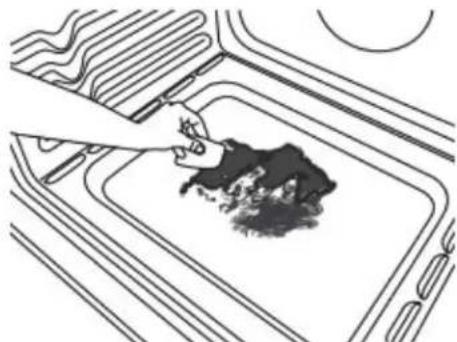
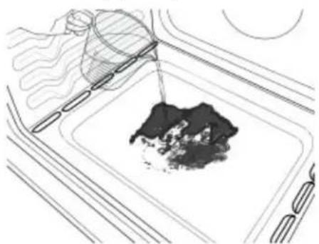
DO NOT ATTEMPT TO EXTINGUISH AN OIL/GREASE FIRE WITH WATER.
hazard
fire
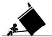
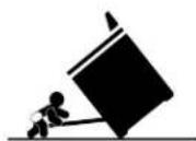
The range will not tip during normal use. However, the range can tip if you apply too much force or weight to the open door without the anti-tip bracket fastened down properly.

AWARNING
Tip Over Hazard
A child or adult can tip the range and be killed.
Install anti-tip bracket to floor or wall per installation instructions.
Slide range back so rear range foot is engaged in the slot of the anti-tip bracket.
Re-engage anti-tip bracket if range is moved.
Do not operate range without anti-tip bracket installed and engaged.
Failure to follow these instructions can result in death or serious burns to children and adult
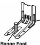
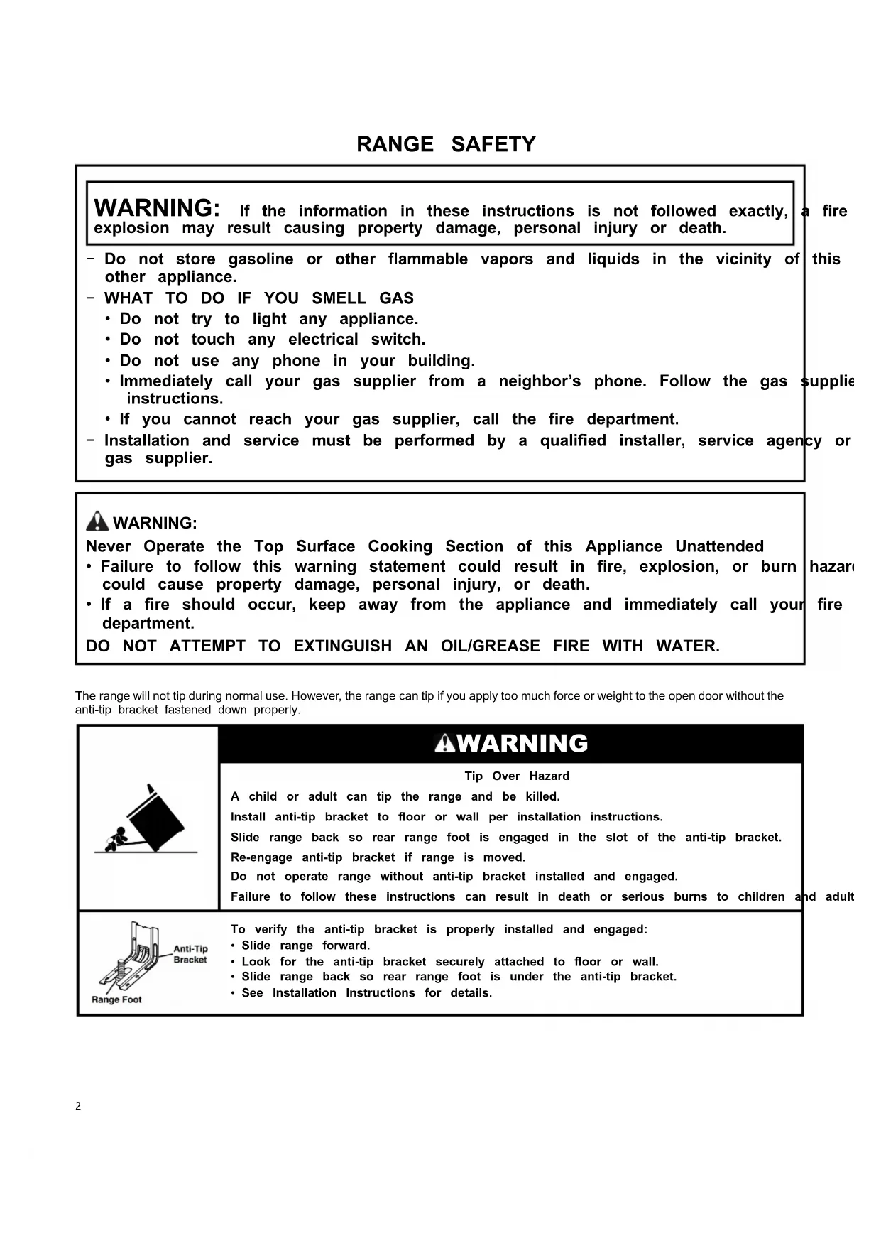
Anti-Tip Bracket
To verify the anti-tip bracket is properly installed and engaged:
- Slide range forward.
- Look for the anti-tip bracket securely attached to floor or wall.
- Slide range back so rear range foot is under the anti-tip bracket.
- See Installation Instructions for details.
WARNING: Gas leaks cannot always be detected by smell.
Gas suppliers recommend that you use a gas detector approved by UL or CSA.
For more information, contact your gas supplier.
If a gas leak is detected, follow the "What to do if you smell gas" instructions.
Your safety and the safety of others are very important.
We have provided many important safety messages in this manual and on your appliance. Always read and obey all safety messages.

This is the safety alert symbol.
This symbol alerts you to potential hazards that can kill or hurt you and others.
All safety messages will follow the safety alert symbol and either the word "DANGER" or "WARNING." These words mean:
ADANGER
WARNING
You can be killed or seriously injured if you don't immediately follow instructions.
All safety messages will tell you what the potential hazard is, tell you how to reduce the chance of injury, and tell you what can happen if the instructions are not followed.
IMPORTANT: Do not install a ventilation system that blows air downward toward this gas cooking appliance. This type of ventilation system may cause ignition and combustion problems with this gas cooking appliance resulting in personal injury or unintended operation.
In the State of Massachusetts, the following installation instructions apply:
■ Installation and repairs must be performed by a qualified or licensed contractor, plumber, or gas fitter qualified or licensed by the State of Massachusetts.
Acceptable Shut-off Devices: Gas Cocks and Ball Valves installed for use shall be listed.
A flexible gas connector, when used, must not exceed 4 feet (121.9 cm).
IMPORTANT SAFETY INSTRUCTIONS
WARNING: To reduce the risk of fire, electric shock, or injury to persons when using the appliance, follow basic precautions, including the following:
WARNING: TO REDUCE THE RISK OF TIPPING OF THE RANGE, THE RANGE MUST BE SECURED BY PROPERLY INSTALLED ANTI-TIP DEVICES. TO CHECK IF THE DEVICES ARE INSTALLED PROPERLY, SLIDE RANGE FORWARD, LOOK FOR ANTI-TIP BRACKET SECURELY ATTACHED TO FLOOR OR WALL, AND SLIDE RANGE BACK SO REAR RANGE FOOT IS UNDER ANTI-TIP BRACKET.
WARNING
NEVER use this appliance as a space heater to heat or warm the room. Doing so may result in carbon monoxide poisoning and overheating of the oven.
WARNING
NEVER cover any slots, holes or passages in the oven bottom or cover an entire rack with materials such as aluminum foil. Doing so blocks air flow through the oven and may cause carbon monoxide poisoning. Aluminum foil linings may also trap heat, causing a fire hazard.
CAUTION: Do not store items of interest to children in cabinets above an appliance or on the backguard of an appliance - children climbing on the appliance to reach items could be seriously injured.
- Do Not Leave Children Alone - Children should not be left alone or unattended in area where appliance is in use. They should never be allowed to sit or stand on any part of the appliance.
SAVE THESE INSTRUCTIONS
IMPORTANT SAFETY INSTRUCTIONS
WARNING: To reduce the risk of fire, electric shock, or injury to persons when using the appliance, follow basic precautions, including the following:
Wear Proper Apparel - Loose-fitting or hanging garments should never be worn while using the appliance.
- User Servicing - Do not repair or replace any part of the appliance unless specifically recommended in the manual. All other servicing should be referred to a qualified technician.
Storage in or on Appliance - Flammable materials should not be stored in an oven or near surface units.
This appliance is not intended for storage.
■ Do Not Use Water on Grease Fires - Smother fire or flame or use dry chemical or foam-type extinguisher.
- Use Only Dry Potholders - Moist or damp potholders on hot surfaces may result in burns from steam. Do not let potholder touch hot surface units. Do not use a towel or other bulky cloth.
- Never Leave Surface Units Unattended at High Heat Settings - Boilover causes smoking and greasy spillovers that may ignite.
Glazed Cooking Utensils - Only certain types of glass, glass/ceramic, ceramic, earthenware, or other glazed utensils are suitable for range-top service without breaking due to the sudden change in temperature.
- Utensil Handles Should Be Turned Inward and Not Extend Over Adjacent Surface Units - To reduce the risk of burns, ignition of flammable materials, and spillage due to unintentional contact with the utensil, the handle of a utensil should be positioned so that it is turned inward, and does not extend over adjacent surface units.
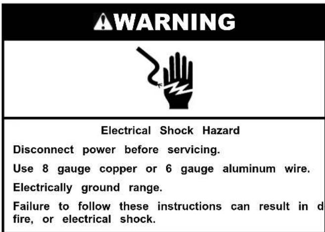
Disconnect power before servicing.
This appliance is equipped with a four-prong grounding plug for your protection against shock hazard and should be plugged directly into a properly grounded receptacle. Do not cut or remove the grounding prong from this plug.
- Proper Installation - The appliance, when installed, must be electrically grounded in accordance with local codes, or in the absence of local codes, with the National Electrical Code, ANSI/NFPA 70 or the Canadian Electrical Code, CSA C22.1-02. In Canada, the appliance must be electrically grounded in accordance with Canadian Electrical Code. Be sure your appliance is properly installed and grounded by a qualified technician.
Injuries may result from the misuse of appliance doors or drawers such as stepping, leaning, or sitting on the doors or drawers.
- Maintenance - Keep range area clear and free from combustible materials, gasoline, and other flammable vapors and liquids.
Top burner flame size should be adjusted so it does not extend beyond the edge of the cooking utensil. This instruction is based on safety considerations.
- Do not use replacement parts that have not been recommended by the manufacturer (e.g. parts made at home using a 3D printer).
Clean Cooktop With Caution - If a wet sponge or cloth is used to wipe spills on a hot cooking area, be careful to avoid steam burn. Some cleaners can produce noxious fumes if applied to a hot surface.
Use Care When Opening Door - Let hot air or steam escape before removing or replacing food.
Do Not Heat Unopened Food Containers - Build-up of pressure may cause container to burst and result in injury.
■ Keep Oven Vent Ducts Unobstructed. - DO NOT TOUCH HEATING ELEMENTS OR INTERIOR SURFACES OF OVEN - Heating elements may be hot even though they are dark in color. Interior surfaces of an oven become hot enough to cause burns. During and after use, do not touch, or let clothing or other flammable materials contact heating elements or interior surfaces of oven until they have had sufficient time to cool. Other surfaces of the appliance may become hot enough to cause burns - among these surfaces are oven vent openings and surfaces near these openings, oven doors, and windows of oven doors.
Care must be taken to prevent aluminum foil and meat probes from contacting heating elements.
For self-cleaning ranges
CAUTION: DO NOT LEAVE FOOD OR COOKING UTENSILS, ETC., IN OVEN DURING THE PYROLYTIC SELF-CLEANING MODE OF OPERATION.
- Do Not Clean Door Gasket - The door gasket is essential for a good seal. Care should be taken not to rub, damage, or move the gasket.
- Do Not Use Oven Cleaners - No commercial oven cleaner or oven liner protective coating of any kind should be used in or around any part of the oven.
Clean Only Parts Listed in Manual.
Before Self-Cleaning the Oven - Remove broiler pan and other utensils. Wipe off all excessive spillage before initiating the cleaning cycle.
For units with ventilating hood
Clean Ventilating Hoods Frequently -Grease should not be allowed to accumulate on hood or filter.
When flaming foods under the hood, turn the fan on.
For smart enabled ranges and ovens
Remote operation - This appliance is configurable to allow remote operation at any time. Do not store any flammable materials or temperature sensitive items inside, on top or near surface units of the appliance.
SAVE THESE INSTRUCTIONS
RANGE MAINTENANCE AND CARE
Clean Cycle
AquaLift®
Self-Cleaning Technology
AquaLift® Technology is an innovative cleaning solution that utilizes heat and water to release baked-on spills from the oven in less than 1 hour. This new cleaning technology is a low-heat, odor-free alternative to traditional self-cleaning options.
Allow the oven to cool to room temperature before using the Clean cycle. If your oven cavity is above 200^ (93^) , it will appear in the display, and the Clean cycle will not be activated until the oven cavity cools down.
To Clean:
- Remove all racks and accessories from the oven cavity, and wipe excess soil. Use a plastic scraper to remove easily removed soils.
- Pour 2 cups (16 oz [500 mL]) of distilled or filtered water onto the bottom of the empty oven, and close the oven door.
IMPORTANT: Do not use chemicals or other additives with the water. Do not open the oven door during the Clean cycle. The water on the oven bottom is hot.
- Press CLEAN/AQUALIFT SELF CLEAN and then STARTon the oven control panel.
- Allow 40 minutes for cleaning and cooldown. A beep will sound when the Clean cycle is complete.
-
Press OFF/CANCEL/CANCEL UPPER at the end of the cycle. OFF/CANCEL/CANCEL UPPER may be pressed at any time to stop the Clean cycle.
-
Remove the residual water and loosened soils with a sponge or cloth immediately after the Clean cycle is complete. Much of the initial 2 cups (16 oz [500 mL]) of water will remain in the oven after the cycle is completed. If additional soils remain, leave a small amount of water in the oven bottom to assist with the cleaning.
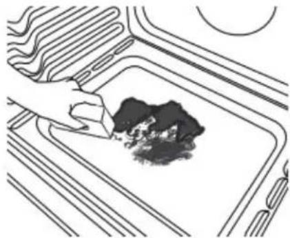
If any soils remain, remove them with a nonscratch scrubbing sponge or plastic scraper. Additional Clean cycles may be run to help remove the stubborn soils.
IMPORTANT: Do not use oven cleaners. The use of chemicals, including commercial oven cleaners or metal scouring pads, may cause permanent damage to the porcelain surface of the oven interior.
NOTE:
The range should be level to ensure that the entire surface of the bottom of the oven cavity is covered by water at the beginning of the Clean cycle.
For best results, use distilled or filtered water. Tap water may leave mineral deposits on the oven bottom.
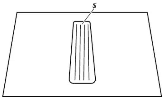
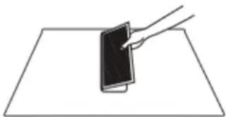
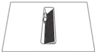
Before removing the residual water and loosened soils at the end of the Clean cycle, insert a cloth or paper towel between the lower edge of the oven door and the front frame to keep water from spilling onto the front of the range and the floor.
Soil baked on through several cooking cycles will be more difficult to remove with the Clean cycle.
Nonabrasive scrub sponges or eraser-style cleaning pads (without cleaners) can be effective for cleaning the oven cavity walls, oven door, and oven bottom for difficult soils. For best results, moisten the pads and sponges before use.
Run an additional Clean cycle for stubborn soils.
- Affresh® Kitchen Appliance Cleaner and affreshCooktop Cleaner may be used to clean the oven bottom, walls, and door when the oven has finished the cycle and returned to room temperature. If affreshCooktop Cleaner is used, it is recommended to wipe out the cavity with distilled water as well. Refer to the Quick Start Guide for ordering information.
Additional AquaLift® Technology Cleaning Kits may be obtained by ordering Part Number W10423113RP. Refer to the Quick Start Guide for ordering information.
General Cleaning
IMPORTANT: Before cleaning, make sure all controls are OFF and the oven and cooktop are cool. Always follow label instructions on cleaning products.
Soap, water, and a soft cloth or sponge are suggested first, under otherwise noted.
EXTERIOR PORCELAIN ENAMEL SURFACES (on some models)
Food spills containing acids, such as vinegar and tomato, should be cleaned as soon as the entire range is cool. These spills may affect the finish.
Cleaning Method:
Glass cleaner, mild liquid cleaner, or nonabrasive scrubbing pad: Gently clean around the model/serial/rating plate because scrubbing may remove numbers.
- Affresh® Kitchen and Appliance Cleaner Part Number W10355010 (not included):
See the Quick Start Guide for ordering information.
STAINLESS STEEL (on some models)
NOTE: To avoid damage to stainless steel surfaces, do not use soap-filled scouring pads, abrasive cleaners, Cooktop Cleaner, steel-wool pads, gritty washcloths, or abrasive paper towels. Damage may occur to stainless steel surfaces, even with one-time or limited use.
Cleaning Method:
Rub in direction of grain to avoid damaging.
■ affresh® Stainless Steel Cleaner Part Number W10355016 (not included):
See the Quick Start Guide for ordering information.
Yellow Heat Stains:
- Add 1 tbs (15~mL) of table salt to 1 / 4 cup (59.1~mL) of vi and then stir for 1 minute. Not all of the salt will dissolve.
- Using a soft cloth, soak up the liquid of the vinegar mixture. Dab the wet cloth onto the yellow stains for 3 to 4 minutes. The wetter the stainless steel is, the better the cleaning resu will be.
- Let sit until the yellow stains have faded. Using a dry soft cloth, wipe off the remaining vinegar mixture.
- Repeat steps 1 to 3 until all yellow stains have been removed
- Using clean water and a fresh soft cloth, clean off any remaining residue. Dry with a clean soft cloth.
- Use affresh Stainless Steel Cleaner Part Number W10355016 (not included) to protect and polish the cleaned surface.
NOTE: Remove surface grates before cleaning rear vent trim. Avoid dripping the vinegar mixture into the vent holes or down back of the range.
METALLIC PAINT (on some models)
Do not use abrasive cleaners, cleaners with bleach, rust removers, ammonia, or sodium hydroxide (lye) because paint surface may stain.
PORCELAIN-COATED GRATES AND CAPS
Food spills containing acids, such as vinegar and tomato, should be cleaned as soon as the cooktop, grates and caps are cool. These spills may affect the finish.
To avoid chipping, do not bang grates, and caps against each other or hard surfaces such as cast iron cookware.
Do not reassemble caps on burners while wet. Do not clean in the Self-Cleaning cycle.
Cleaning Method:
Nonabrasive plastic scrubbing pad and mildly abrasive cleanser: Clean as soon as cooktop, grates, and caps are cool.
Dishwasher (grates only, not caps):
Use the most-aggressive cycle. Cooked-on soils should be soaked or scrubbed before going into a dishwasher.
Although the burner grates are durable, they may lose their shine and/or discolor when washed in a dishwasher.
Gas Grate and Drip Pan Cleaner Part Number 31617 (not included):
See the Quick Start Guide for ordering information.
SURFACE BURNERS
Food spills containing acids, such as vinegar and tomato, should be cleaned as soon as the cooktop, grates, and caps are cool. These spills may affect the finish.
To avoid chipping, do not bang grates and caps against each other or hard surfaces such as cast iron cookware.
Do not reassemble caps on burners while wet.
Do not clean in the Self-Cleaning cycle.
Do not clean in dishwasher.
Cleaning Method:
Nonabrasive plastic scrubbing pad and mildly abrasive cleanser:
Clean as soon as cooktop, grates, burners, and caps are cool.
Gas Grate and Drip Pan Cleaner (not included).
COOKTOP CONTROLS
To avoid damage to the cooktop controls, do not use steel wool, abrasive cleansers, or oven cleaner.
Ebarvoid damage, do not soak knobs. When replacing knobs, make sure knobs are in the Off position.
On some models, do not remove seals under knobs.
Cleaning Method:
Soap and water: Pull knobs straight away from control panel to remove
GRIDDLE (on some models)
To avoid damaging the nonstick surface, do not use steel wool or abrasive cleaners.
Cleaning Method:
Mild detergent.
- Dishwasher: Although the griddle is durable, it may lose its shine and/or is color when washed in a dishwasher.
CONTROL PANEL AND OVEN DOOR EXTERIOR
④ avoid damage to the control panel, do not use abrasive cleaners, steel-wool pads, gritty washcloths, or abrasive paper towels.
Cleaning Method:
Glass cleaner and soft cloth or sponge: Apply glass cleaner to soft cloth or sponge, not directly on panel.
- Affresh® Kitchen and Appliance Cleaner Part Number W10355010 (not included):
See the Quick Start Guide for ordering information.
OVEN RACKS
Cleaning Method:
Steel-wool pad.
For racks that have discolored and are harder to slide, a light coating of vegetable oil applied to the rack guides will help them slide.
- Dishwasher (steam rack water reservoir only, not racks): Although the water reservoir is durable, it may lose its shine and/or discolor when washed in a dishwasher.
BAKING DRAWER (on some models)
Check that baking drawer is cool and empty before cleaning.
Food spills should be cleaned when oven cools. At high temperatures, foods react with porcelain. Staining, etching, pitting, or faint white spots can result.
Cleaning Method:
Mild detergent
STORAGE/WARMING DRAWER (on some models)
Check that storage/warming drawer is cool and empty before cleaning.
Cleaning Method:
Mild detergent
OVEN CAVITY
Use AquaLift Technology regularly to clean oven spills.
Do not use oven cleaners.
Food spills should be cleaned when oven cools. At high temperatures, foods react with porcelain. Staining, etching, pitting, or faint white spots can result.
Cleaning Method:
Self-Cleaning cycle: See the "Self-Cleaning Cycle" or "Clean Cycle" section first.
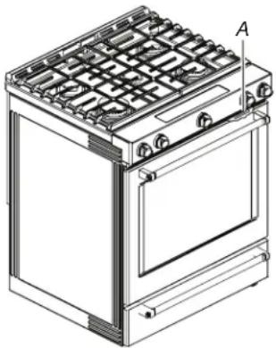
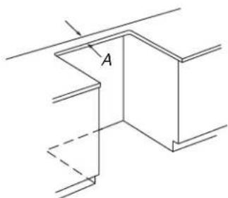
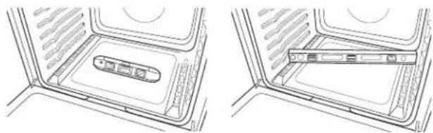
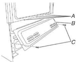
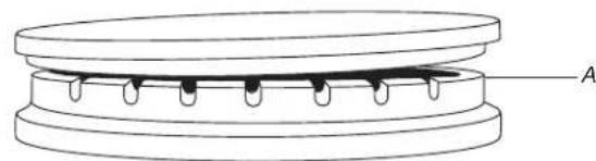
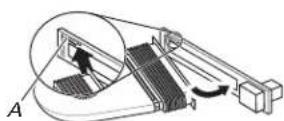
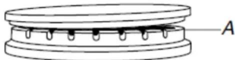
Downdraft ventilation system
Vent Grade
Cleaning Method:
- Lift the vent grate off the cooktop.
A. Vent grate
Nonabrasive plastic scrubbing pad and mildly abrasive cleanser: Wipe clean or wash in sink.
- Dishwasher: Use mild detergent.
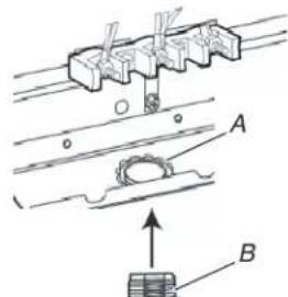
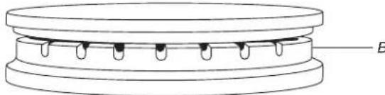
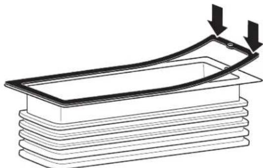
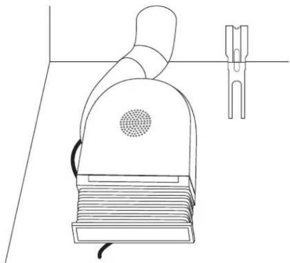
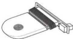
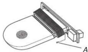
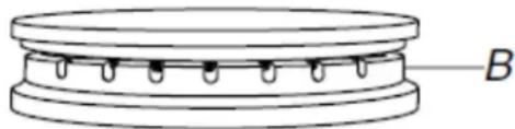
Filter
The filter is a permanent type and should be cleaned when soile
Cleaning Method:
Turn off the downdraft ventilation system before removing the filter.
Remove vent grate, and then lift the filter out of the vent chamber.
Clean the filter in the sink with warm water and detergent or in the dishwasher.
Replace the filter.
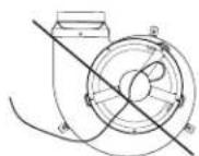
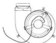
The filter should always be placed at an angle. As you face the front of the range, the top of the filter should rest against the right side of the vent opening. The bottom of the filter should rest against the left side of the vent chamber at the bottom. If the filter is flat against the fan wall, ventilation effectiveness will be reduced.
Ventilation Chamber
The ventilation chamber, which houses the filter, should be cleaned in the event of spills or when it becomes coated with a film of grease.
Cleaning Method:
Mild household detergent or cleanser and paper towel, damp cloth or sponge:
Apply detergent or cleanser to paper towel, damp cloth or sponge, not directly to the ventilation chamber.
INSTALLATION INSTRUCTIONS REQUIREMENTS
Tools and Parts
Gather the required tools and parts before starting installation. Read and follow the instructions provided with any tools listed here.
Tools needed
Tape measure
■ Phillips screwdriver
Flat-blade screwdriver
1/8" (3.2 mm) flat-bladescrewdriver
Hand or electric drill
Level
Wrench or pliers
Pipe wrench
15/16" (2.4 cm) combination wrench
1/8" (3.2 mm) drill bit
Torque Wrench
Marker or pencil
Pipe-joint compound resistant to propane gas
3/16" (4.8 mm) carbide-tipped masonry drill bit (for concrete/ceramic floors)
Noncorrosive leak-detection solution
For Propane/Natural Gas Conversions
1/2" (1.3 cm) combination wrench
1/4" (6 mm) nut driver
9/32" (7.0 mm) nut driver
■ Masking tape
Parts supplied
Check that all parts are included.
Propane/Natural Gas Conversion Kit
10-32 hex nuts (attached to terminal block) (3)
Direct wire lugs (3)
■ #10 x 18 " (4.1 cm) screws (for mounting anti-tip bracket) (2)
Anti-tip bracket (inside oven cavity)
Anti-tip bracket must be securely mounted to the back wall of floor. Thickness of flooring may require longer screws to anchor bracket to subfloor. Longer screws are available from your local hardware store.
Parts Needed
If using a power supply cord kit:
A UL listed power supply cord kit marked for use with ranges The cord should be rated at 250V minimum, 40 A or 50 A is marked for use with nominal _8^ 1 (3.5 cm diameter connection opening and must end in ring terminals or open-end spade terminals with upturned ends.
A UL listed strain relief.
Check local codes and consult gas supplier. Check existing gas supply and electrical supply. See the appropriate "Electrical Requirements" and "Gas Supply Requirements" sections.
It is recommended that all electrical connections be made by a licensed, qualified electrical installer.
NOTE: Be sure to purchase only Whirlpool factory-certified parts and accessories for your appliance. Your installation may require additional parts. To order, refer to the contact information referenced in your Quick Start Guide.
Optional Parts
To purchase side trim kits, backsplash kits, or any other accessories see the Quick Start Guide for ordering information.
NOTE: Be sure to purchase only Whirlpool factory-certified parts and accessories for your appliance. Your installation may require additional parts. To order, refer to the contact information referenced in your Quick Start Guide.
Location Requirements
IMPORTANT: Observe all governing codes and ordinances. Do not obstruct flow of combustion and ventilation air.
It is the installer's responsibility to comply with installation clearances specified on the model/serial/rating plate. The model/serial/rating plate is located behind the oven door on the top right-hand side of the oven frame.
The range should be located for convenient use in the kitchen.
- Recessed installations must provide complete enclosure of the sides and rear of the range.
All openings in the wall or floor where range is to be installed must be sealed.
Cabinet opening dimensions that are shown must be used. Given dimensions are minimum clearances.
The anti-tip bracket must be installed. To install the anti-tip bracket shipped with the range, see "Install Anti-Tip Bracket" section.
Grounded electrical supply is required. See the appropriate "Electrical Requirements" section.
Proper gas supply connection must be available. See "Gas Supply Requirements" section.
- Contact a qualified floor covering installer to check that the floor covering can withstand at least 200^ (93^) .
Use an insulated pad or 1/4'' (6.4 mm) plywood under range if installing range over carpeting.
IMPORTANT: To avoid damage to your cabinets, check with your builder or cabinet supplier to make sure that the materials used will not discolor, delaminate or sustain other damage. This oven has been designed in accordance with the requirements of UL and CSA International and complies with the maximum allowable wood cabinet temperatures of 194^ (90^) .
Mobile Home - Additional Installation Requirements
The installation of this range must conform to the Manufactured Home Construction and Safety Standard, Title 24 CFR, Part 3280 (formerly the Federal Standard for Mobile Home Construction and Safety, Title 24, HUD Part 280). When such standard is not applicable, use the Standard for Manufactured Home Installations, ANSI A225.1/NFPA 501A or with local codes.
In Canada, the installation of this range must conform with the current standards CAN/CSA Z240.1 - latest edition, or with local codes.
Mobile Home Installations Require:
- When this range is installed in a mobile home, it must be secured to the floor during transit. Any method of securing the range is adequate as long as it conforms to the standards listed above.
Four-wire power supply cord or cable must be used in a mobile home installation. The appliance wiring will need to be revised. See "Electrical Connection - U.S.A. Only" section.
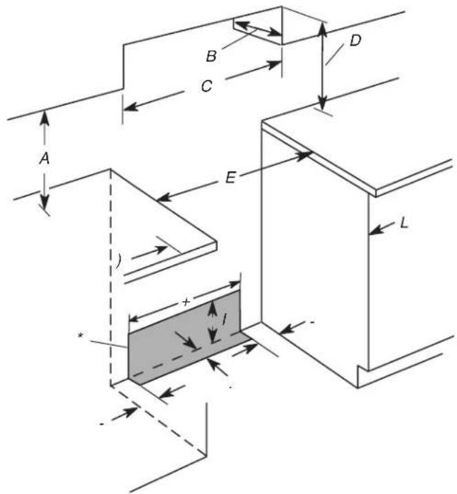
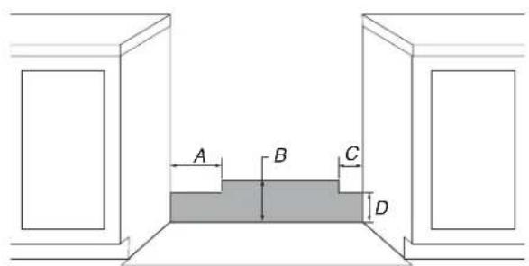
Cabinet Dimensions
Cabinet opening dimensions shown are for 25" (64.0 cm) countertop depth, 24" (61.0 cm) base cabinet depth and 36" (91.4 cm) countertop height.
IMPORTANT: If installing a range hood or microwave hood combination above the cooking surface, follow the range hood or microwave hood combination installation instructions for dimensional clearances above the cooktop surface.
NOTE: When installed in a slide-in cutout, the front of oven door may protrude beyond the base cabinet.
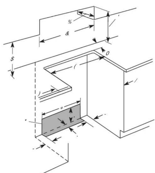
Slide-in Cutout Freestanding Cutout
A. 18^ (45.7 cm) upper side cabinet to countertop
B. 13'' (33 cm) maximum upper cabinet depth
C. 30^ (76.2 cm) minimum opening width
D. For minimum clearance to top of cooktop, see NOTE*.
E. 30^ (76.5 cm) minimum opening width
F. 5^ (12.7 cm) minimum clearance from both sides of range to side or other combustible material
G. The shaded area is recommended for installation of rigid gas pipe grounded outlet
H. 13% (33.3 cm)
- 7^11 / 16 (19.5 cm)
J. 4^13 / 16 (12.2 cm)
K. 3^11 / 16 (9.4 cm) plus measurement of M
L. Cabinet door or hinges should not extend into the cutout.
M. Remaining counter depth should not exceed/42 (5.7 cm)
A. 18^ (45.7 cm) upper side cabinet to countertop
B. 13'' (33 cm) maximum upper cabinet depth
C. 30^ (76.2 cm) minimum opening width
D. For minimum clearance to top of cooktop, see NOTE*.
E. 30^ (76.2 cm) minimum opening width
Wall5" (12.7 cm) minimum clearance from both sides of range to side wall or other combustible material
EndThe shaded area is recommended for installation of rigid gas pipe and grounded outlet.
H. 13^1 / 8 (33.3 cm)
1. 7^11 / 16 (19.5 cm)
J. 4^13y_16'' (12.2 cm)
K. 3^11 / 16 (9.4 cm)
L. Cabinet door or hinges should not extend into the cutout.
NOTE*: 24" (61.0 cm) minimum when bottom of wood or metal cabinet is shielded by not less than 1/4" (6.4 mm) flame retardant millboard covered with not less than No. 28 MSG sheet steel, 0.015" (0.4 mm) stainless steel, 0.024" (0.6 mm) aluminum or 0.020" (0.5 mm) copper.
30^ (76.2 cm) minimum clearance between the top of the cooking platform and the bottom of an uncovered wood or metal cabinet.
Venting Requirements
IMPORTANT: This range must be exhausted outdoors unless are using ductless venting. See the "Venting Methods" section.
- Do not terminate the vent system in an attic or other enclosure area.
Use an approved vent cap for proper performance. If an alternate wall or roof cap is used, be certain the cap size is reduced and that it has a backdraft damper. - Vent system must terminate to the outside unless you are using a ductless vent kit.
Use a 5^ (12.7 cm) or 6^ (15.2 cm) round metal vent or a 31/4'' x 10'' (8.3 cm x 25.4 cm) rectangular vent.
Rigid metal vent is recommended. For best performance, do not use plastic or metal foil vent.
If a joist or stud must be cut, then a supporting frame must be constructed.
The size of the vent should be uniform.
The vent system must have a damper. - Seal all joints in the vent system.
Use caulking to seal exterior wall or roof opening around the cap.
Determine which venting method is best for your application.
For Best Performance:
Use 26-gauge minimum galvanized or 25-gauge minimum aluminum metal vent. Poor quality pipe fittings can reduce airflow. For external venting, flexible metal vent is not recommended.
NOTE:
For external venting, flexible metal vent is not recommended. Flexible vent creates back pressure and turbulence that greatly reduce performance.
Local codes may require a heavier gauge material.
Metal duct may be reduced to 30-gauge galvanized steel or 26-gauge aluminized steel if allowed by local codes. This reduction is based on information in the International Residential Codes Section M1601.1 (2006 edition).
Avoid installing 2 elbows together.
Use no more than three 90^ elbows.
Make sure there is a minimum of 18^ (45.7 cm) of straight vent between the elbows if more than one elbow is used. Elbows too close together can cause excess turbulence that reduces airflow.
■ Do not use a 5^ (12.7 cm) elbow in a 6^ (15.2 cm) or 31 / 4^ × 10^ (8.3 x 25.4 cm) system.
■ Do not reduce to a 5^ (12.7 cm) system after using a 6^ (15.2 cm) or 1 / 3^ × 10^ (8.3 x 25.4 cm) fittings.
- Avoid forming handmade crimps. Handmade crimps may restrict airflow.
The length of vent system and number of elbows should be kept to a minimum to provide efficient performance.
The maximum equivalent length of the vent system is 60 ft (18.3 m). For altitudes above 4,500 ft (1272 m), reduce recommended vent run by 20% for best performance.
Cold Weather Installations
An additional backdraft damper should be installed to minimize backward cold air flow and a thermal break installed to minimize conduction of outside temperatures as part of the vent system. The damper should be on the cold air side of the thermal break. Order Part Number 708786A for a 5^ (12.7 cm) thermal break. Order Part Number 715557A for a 6^ (15.2 cm) thermal break. Refer to the Quick Start Guide for ordering information.
Makeup Air
Local building codes may require the use of makeup air systems when using ventilation systems greater than specified CFM of air movement. The specified CFM varies from locale to locale.
Consult your HVAC professional for specific requirements in your area.
Venting Methods
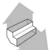
Common venting methods are shown for a downdraft range. The downdraft range may be vented through the wall or floor.
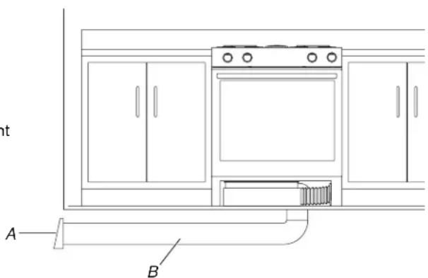
Wall Venting
A. Wall cap
B. Venting
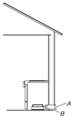
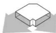
Floor Venting
Venting Between Floor Joists
A. Wall cap
B. Venting
Calculating Vent System Length
IMPORTANT: This range is rated at 60 ft (18.3 m) of 6'' (15.2 or 30 ft (9.15 m) of 5'' (12.7 cm) straight duct. To calculate the length of the system you need, add the equivalent feet (meters) for each vent piece used in the system.
| Vent Piece 5" (12.7 cm) or 6" (15.2 cm) Round | |
| Straight round | |
| 45° elbow 2.5 ft | (0.8 m) |
| 90° elbow 5.0 ft | (1.5 m) |
| 6" (15.2 cm) wall cap | 0.0 ft (0.0 m) |
| 31/4" x 10" (8.3 cm 4.5 ft 25.4 cm) to 6" (15.2 cm) transition | (1.4 m) |
| 6" (15.2 cm) to1/4" x 10" (8.3 cm x 25.4 cm) transition | 1 ft (0.3 m) |
| 31/4" x 10" (8.3 cm 5.0 ft 25.4 cm) to 6" (15.2 cm) 90° elbow transition | (1.5 m) |
| 6" (15.2 cm) to1/3" x 10" (8.3 cm x 25.4 cm) 90° elbow transition | 5.0 ft (1.5 m) |
Vent Piece 5" (12.7 cm) or 6" (15.2 cm) Round
31 / 4'' x 10" (8.3 cm 5.0 ft 25.4 cm) 90^ elbow (1.5 m)
31/4" x 10" (8.3 cm x2.0 ft 25.4 cm) flat elbow (3.7 m)
31/4" x 10" (8.3 cm 0.0 ft 25.4 cm) wall cap (0.0 m)
Straight 3 / 4^ × 10^ (8.3 cm x 25.4 cm)
5" (12.7 cm) 2.0 ft
thermal break (0.6 m)
Part Number 708786A
6" (15.2 cm) thermal break Part Number 715557A
Example 6" (15.2 cm) vent system Venting Between Floor Joists
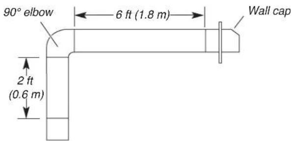
Maximum length = 60 ft (18.3 m)
1- 90^ elbow = 5 ft (1.5 m)
8 ft (2.4 m) straight = 8 ft (2.4 m)
1 - wall cap = 0 ft (0 m)
System length = 13 ft (3.9 m)
NOTE: For external venting, a flexible vent is not recommended. Flexible vents create back pressure and air turbulence that greatly reduce performance.
Electrical Requirements - U.S.A. Only
If codes permit and a separate ground wire is used, it is recommended that a qualified electrical installer determine that the ground path and wire gauge are in accordance with local codes.
Do not use an extension cord.
Be sure that the electrical connection and wire size are adequate and in conformance with the National Electrical Code, ANSI/ NFPA 70-latest edition and all local codes and ordinances.
A copy of the above code standards can be obtained from:
National Fire Protection Association
1 Batterymarch Park Quincy, MA 02169-7471
WARNING: Improper connection of the equipment-grounding conductor can result in a risk of electric shock. Check with a qualified electrician or service technician if you are in doubt as to whether the appliance is properly grounded. Do not modify the power supply cord plug. If it will not fit the outlet, have a proper outlet installed by a qualified electrician.
Electrical Connection
To properly install your range, you must determine the type of electrical connection you will be using and follow the instructions provided for it here.
- Range must be connected to the proper electrical voltage and frequency as specified on the model/serial/rating plate. The model/serial/rating plate is located behind the oven door on the top right-hand side of the oven frame.
A. Model/serial/rating plate (located behind the oven door on the top right-hand side of the oven frame)
Range Rating* Specified Rating of
Power Supply
Cord Kit and
Circuit Protection
120/240 V 120/208 V Ampere
8.8-16.5 kW 7.8-12.5 kW 40 or 50^**
16.6-22.5 kW 12.6-18.5 kW 50
*The NEC calculated load is less than the total connected load listed on the model/serial/rating plate.
**If connecting to a 50 A circuit, use a 50 A rated cord with kit. For 50 A rated cord kits, use kits that specify use with a nominal 1 (3.5 cm) diameter connection opening.
A circuit breaker is recommended.
The range can be connected directly to the circuit breaker box (or fused disconnect) through flexible or nonmetallic sheathed, copper or aluminum cable. See the "Electrical Connection -U.S.A. Only" section.
- Allow at least 6 ft (1.8 m) of slack in the line so that the range can be moved if servicing is ever necessary.
A UL listed conduit connector must be provided at each end of the power supply cable (at the range and at the junction box).
- Wire sizes and connections must conform with the rating of the range.
The tech sheet is available online, and the wiring diagram is located on the back of the range in a plastic bag.
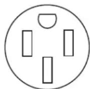
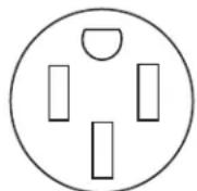
This range is equipped with a CSA International Certified Power Cord intended to be plugged into a standard 14-50R wall receptacle. Be sure the wall receptacle is within reach of range's final location.
Do not use an extension cord.
Electrical Requirements - Canada Only

AWARNING
Electrical Shock Hazard
Electrically ground appliance.
Failure to do so could result in death, fire, or electrical shock.
If codes permit and a separate ground wire is used, it is recommended that a qualified electrical installer determine that the ground path is adequate and wire gauge are in accordance with local codes.
Be sure that the electrical connection and wire size are adequate and in conformance with CSA Standard C22.1, Canadian Electrical Code, Part 1 - latest edition, and all local codes and ordinances.
A copy of the above code standards can be obtained from:
Canadian Standards Association
178 Rexdale Blvd
Toronto, ON M9W 1R3 CANADA
- Check with a qualified electrical installer if you are not sure the range is properly grounded.
Range Rating* Specified Rating
of Power Supply Cord kit and Circuit Protection
120/240 V 120/208 V Ampere
8.8-16.5 kW 7.8-12.5 kW 40 or 50^**
16.6-22.5 kW 12.6-18.5 kW 50
The NEC calculated load is less than the total connected load listed on the model/serial/rating plate.
*If connecting to a 50 A circuit, use a 50 A rated cord with k 50 A rated cord kits, use kits that specify use with a nominal (3.5 cm) diameter connection opening.
A circuit breaker is recommended.
This range is equipped with a CSA International Certified Power Cord intended to be plugged into a standard 14-50R wall receptacle. Be sure the wall receptacle is within reach of range's final location.
- Do not use an extension cord.
Gas Supply Requirements
AWARNING
Explosion Hazard
Use a new CSA International approved gas supply Install a shut-off valve.
Securely tighten all gas connections.
If connected to propane, have a qualified person make sure gas pressure does not exceed 14" (36 cm) water column.
Examples of a qualified person include: licensed heating personnel, authorized gas company personnel, and authorized service personnel.
Failure to do so can result in death, explosion, or fire.
Observe all governing codes and ordinances.
IMPORTANT: This installation must conform with all local codes and ordinances. In the absence of local codes, installation must conform with the National Fuel Gas Code ANSI Z223.1/NFPA 54 or, in Canada, the National Gas and Propane Installation Code, CSA B149.1 - latest edition.
IMPORTANT: Leak testing of the range must be conducted according to the manufacturer's instructions. See the "Make Gas Connection" section for leak testing instructions.
TEFLON is a registered trademark of Chemours.
Type of Gas
Natural Gas:
This range is factory set for use with Natural gas. If converting to propane gas, see "Gas Conversions" section. The model/serial/rating plate located behind the control panel has information on the types of gas that can be used. If the types of gas listed do not include the type of gas available, check with the local gas supplier.
Propane Gas Conversion:
Conversion must be done by a qualified service technician.
No attempt shall be made to convert the appliance from the gas specified on the model/serial/rating plate for use with a different gas without consulting the serving gas supplier. See "Gas Conversions" section.
Gas Supply Line
■ Provide a gas supply line of 3/4'' (1.9 cm) rigid pipe to the range location. A smaller size pipe on longer runs may result in insufficient gas supply. With propane gas, piping or tubing size can be 1/2'' (1.3 cm) minimum. Usually, propane gas suppliers determine the size and materials used in the system.
NOTE: Pipe-joint compounds that resist the action used. Do not use TEFLON† tape.
Flexible metal appliance connector:
If local codes permit, a new CSA design-certified, 4 to 5 ft (122 to 152.4~cm long, 1 / 2'' (1.3cm) or 3 / 4'' (1.9cm) I.D., flexible metal appliance connector may be used for connecting range to the gas supply line.
A 1 / 2^ (1.3 cm) male pipe thread is needed for connection to the female pipe threads of the inlet to the appliance pressure regulator.
- Do not kink or damage the flexible metal tubing when moving the range.
Must include a shutoff valve:
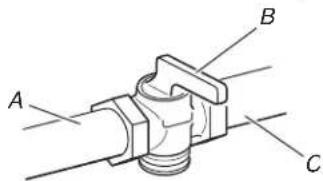
Install a manual gas line shut-off valve in an easily accessible location. Do not block access to shut-off valve. The valve is for turning on or shutting off gas to the range.
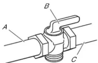
A. Gas supply line
B.Shutoff valve "open" position
C. To range
Gas Pressure Regulator
The gas pressure regulator supplied with this range must be used sheet of cardboard or hardboard on the floor in front of range to The inlet pressure to the regulator should be as follows for proproct the flooring. Using 2 or more people, stand range back up operation: onto the cardboard or hardboard.
Natural gas:
Minimum pressure: 5" (12.7 cm) WCP
Maximum pressure: 14^ (35.6 cm) WCP
Propane gas:
Minimum pressure: 11^ (27.9 cm) WCP
Maximum pressure: 14^ (35.6 cm) WCP
Contact local gas supplier if you are not sure about the inlet pressure.
Burner Input Requirements
Input ratings shown on the model/serial rating plate are for elevations up to 2,000 ft (609.6 m).
For elevations above 2,000 ft (609.6 m), ratings are reduced at rate of 4% for each 1,000 ft (304.8 m) above sea level (not applicable for Canada).
Gas Supply Pressure Testing
Gas supply pressure for testing regulator must be at least 1^ (2.5 cm) water column pressure above the manifold pressure shown on the model/serial rating plate.
Line pressure testing above 1/2 psi (3.5 kPa) gauge [14" (35.6 cm) WCP]
The range and its individual shutoff valve must be disconnected from the gas supply piping system during any pressure testing or that system at test pressures in excess of 1/2 psi (3.5kPa) .
Line pressure testing at 1/2 psi (3.5 kPa) gauge [14" (35] WCP] or lower 2.
The range must be isolated from the gas supply piping system by closing its individual manual shutoff valve during any pressure testing of the gas supply piping system at test pressures equal to or less than 1/2 psi (3.5 kPa).
INSTALLATION
Unpack Range
AWARNING
Excessive Weight Hazard
Use two or more people to move and install or uninstall appliance.
Failure to do so can result in back or other injury.
- Remove shipping materials, tape and film from the range. Keep cardboard bottom under range. Do not dispose of anything until the installation is complete.
- Remove oven racks and parts package from oven and shipping materials.
- To remove cardboard bottom, first take 4 cardboard corners from the carton. Stack one cardboard corner on top of another. Repeat with the other 2 corners. Place them lengthwise on the floor behind the range to support the range when it is laid on its back.
- Using 2 or more people, firmly grasp the range and gently lay it on its back on the cardboard corners.
- Remove cardboard bottom. The leveling legs can be adjusted while the range is on its back. See the "Adjust Leveling Legs" section.
NOTE: To place range back up into a standing position, put a sheet of cardboard or hardboard on the floor in front of range to protect the flooring. Using 2 or more people, stand range back up onto the cardboard or hardboard.
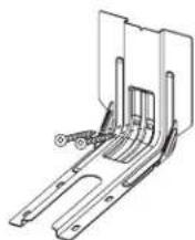
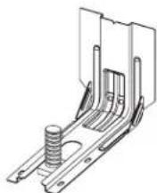
Install Anti-Tip Bracket
AWARNING
Tip Over Hazard
A child or adult can tip the range and be killed.
Install anti-tip bracket to floor or wall per installation instructions.
Slide range back so rear range foot is engaged in the slot of the anti-tip bracket.
Re-engage anti-tip bracket if range is moved.
Do not operate range without anti-tip bracket installed and engaged.
Failure to follow these instructions can result in death or serious burns to children and adults.
56 Remove the anti-tip bracket from the inside of the oven.
- Determine which mounting method to use: floor or wall.
If you have a stone or masonry floor, you can use the wall mounting method. If you are installing the range in a mobile home, you must secure the range to the floor.
This anti-tip bracket and screws can be used with wood or metal studs.
- Determine and mark centerline of the cutout space. The mounting bracket can be installed on either the left-hand or right-hand side of the cutout. Position mounting bracket against the wall in the cutout so that the V-notch of the bracket is 12/2 (31.8 cm) from centerline, as shown.
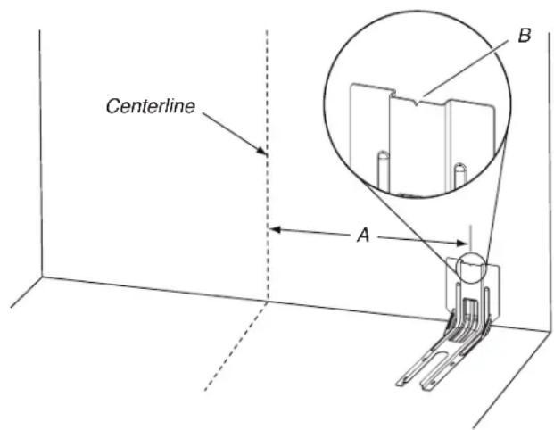
A. 121 / 2'' (31.8 cm)
B. Bracket V-notch
- Drill two 1/8 (3 mm) holes that correspond to the bracket holes of the determined mounting method. See the following illustrations.
Floor Mounting
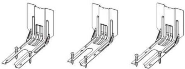
Rear position Front position Diagonal (2 options)
Wall Mounting
- Using the two # 10 = 14 (4.1 cm) Phillips-head screws provided, mount anti-tip bracket to the wall or floor.
- Move range close enough to opening to allow for final electrical connections. Remove shipping base, cardboard, or hardboard from under range.
- Move range into its final location, making sure rear leveling leg slides into anti-tip bracket.
- Move range forward onto shipping base, cardboard or hardboard to continue installing the range, using the following installation instructions.
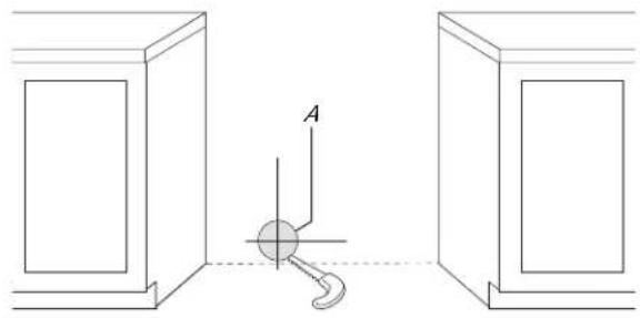
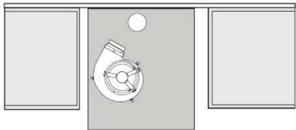
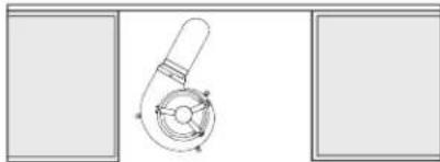
Position the Blower Location Template
- Determine and mark the centerline on the floor of the cabinet opening.
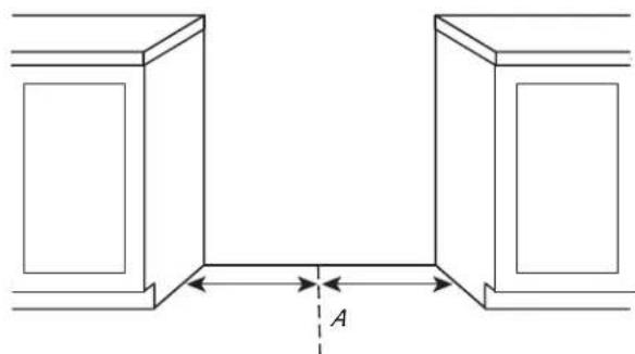
A. Centerline
- Locate the blower location template in the Installation Parts Kit.
- If the countertop extends behind the opening, measure the distance from the back edge of the cabinet cutout to the wall.
A. Countertop Filler Depth
- Fold the top of the blower mounting/venting template on the line that corresponds to the countertop depth measured in Step 3.
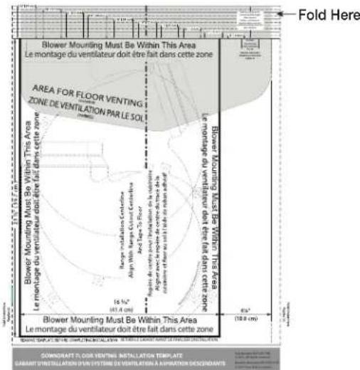
NOTE: The template has lines every 1/4" (6.4 mm) from the back edge. If the distance measured in the previous step is 114 (32 mm), fold the template on the line labeled 1 (32 mm). If there is no countertop filler depth, fold the template at zero depth.
- Align the template centerline with the centerline marked on th2. Draw an outline of the vent on the wall and cut the vent hole. floor. Align the folded edge of the template against the rear wall.
NOTE: Secure the template to the floor with tape.
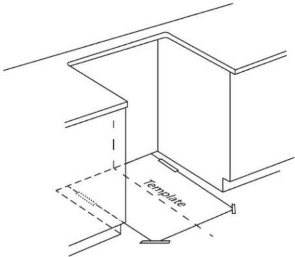
Install the Downdraft System
Determine which venting method to use: floor or rear wall venting. Go to the section for your type of venting. Consider the location of all utilities and ducts prior to determining final position to ensure proper fit and location.
Rear Wall Venting
- Determine where within area illustrated below the vent will exit. Mark the vent hole for the type of venting you are using. 0. 10. 10. 10. 10. 10. 10. 10. 10. 10. 10. 10. 10. 10. 10. 10. 10. 10. 10. 10. 10. 10. 10. 10. 10. 10. 0
Check for obstructions (plumbing, electrical, wall studs, etc.) before marking the vent hole location.
The home venting system should terminate within the defined area using 5^ (12.7 cm) round venting.
A. 12^ (30.5cm)
C. 8'' (20.3 cm)
B. 7 12'' (19 ~cm)
D. 5% (14 cm)
A. Vent hole
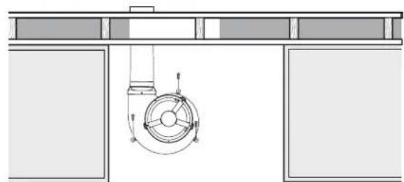
- Locate the blower.
- Locate the blower outlet adapter in the installation parts kit.
- Install the blower outlet adapter to the blower vent using three 8 - 18 × 3 / 8 screws. Seal the connection with aluminum foil tape.
- Remove three felt pads from the gasket strip.
- Remove the paper backing from the felt pads and apply to the bottom of blower motor tabs.
NOTE: Felt pads reduce motor noise and aid in mounting to uneven floors.
Position the blower on the template so that the blower outlet adapter aligns with the home venting.
IMPORTANT: Make sure the blower motor is positioned within the area as shown on the template.
- Connect the home vent system to the blower outlet adapter using sheet metal screws. Seal the connection with aluminum foil tape.
- Drill three 1/8" (3 mm) pilot holes using the holes in the blower motor tabs as guides.
- Remove the template.
- Mount the blower motor to the floor with three #10 x 1" screws provided.
13. Go to the "Make Gas Connection" section.
Floor Venting
- Determine where within the template area that the vent will exit. Mark the vent hole for the type of venting you are using.
IMPORTANT: Check for obstructions (plumbing, electrical, etc.) before marking the vent hole location.
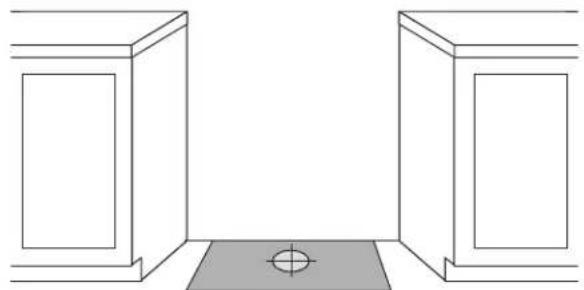
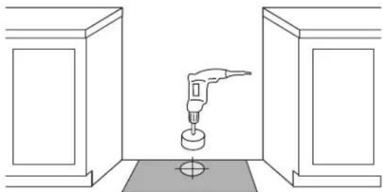
- Draw and cut the vent hole in the floor.
- Install the blower outlet adapter to the blower vent using three 8-18 x 3/8" screws. Seal the connection with aluminum foil tape.
- Remove three felt pads from the gasket strip.
- Remove the paper backing from the felt pads and apply the bottom of a blower motor tabs. NOTE: Felt pads reduce motor noise and aid in mounting to uneven floors.
- Position the blower motor in the cabinet opening so that the blower exhaust venting aligns with the vent hole cut in Step 1.
IMPORTANT: Make sure the blower motor is positioned within the area as shown on the template.
- Connect the house vent system to the blower outlet adapter using a vent clamp; then wrap connection with aluminum tape.
- Drill three 1/8 (3 mm) pilot holes using the blower motor tabs as guides.
-
Remove the template.
-
Mount the blower motor to the floor with three #10 x 1" screws provided.
Top View
- Go to the "Make Gas Connection" section.
Adjust Leveling Legs
- If range height adjustment is necessary, use a wrench or pliers to loosen the 4 leveling legs.
This may be done with the range on its back or with the range supported on 2 legs after the range has been placed back to a standing position.
NOTE: To place range back up into a standing position, put a sheet of cardboard or hardboard in front of range. Using 2 or more people, stand range back up onto the cardboard or hardboard.
AWARNING
Tip Over Hazard
A child or adult can tip the range and be killed. Install anti-tip bracket to floor or wall per installation instructions.
Slide range back so rear range foot is engaged in the slot of the anti-tip bracket.
Re-engage anti-tip bracket if range is moved.
Do not operate range without anti-tip bracket installed and engaged.
Failure to follow these instructions can result in death or serious burns to children and adults.
- Measure the distance from the top of the counter to the floor.
- Measure the distance from the top of the cooktop to the bottom of the leveling legs. This distance should be the same. If it is not, adjust the leveling legs to the correct height. The leveling legs can be loosened to add up to a maximum of 1" (2.5 cm). A minimum of 3/16" (5 mm) is needed to engage the anti-tip bracket.
NOTE: If height adjustment is made when range is standing, tilt the range back to adjust the front legs, and then tilt forward to adjust the rear legs.
- When the range is at the correct height, check that there is adequate clearance under the range for the anti-tip bracket. Before sliding range into its final location, check that the anti-tip bracket will slide under the range and onto the rear leveling leg prior to anti-tip bracket installation.
NOTE: If a Trim Kit will be used, the top of the cooktop should be higher than the counter. See the Installation Instructions included with the Trim Kit for the correct height.
Level Range
- Place level on the oven bottom, as indicated in one of the two figures below, depending on the size of the level. Check with the level side to side and front to back.
- If range is not level, use a wrench or pliers to adjust leveling legs up or down until the range is level. NOTE: Range must be level for satisfactory baking performance and best cleaning results using AquaLift Self-Clean Technology.
Electrical Connection - U.S.A. Only
If your home has a 4-wire direct connection, go to "Install Using Direct Wire".
Install Using Direct Wire
Direct Wire Strain Relief
- Disconnect power.
- Remove the lower access cover screws located on the back the range. Pull the bottom of the cover toward you and out remove cover from range.
A. Mounting tabs (3)
B. Lower access cover
C. Screws (2)
- Assemble a UL listed conduit connector in the opening.
A. Removable retaining nut
B. Conduit
- Tighten strain relief screw against the flexible conduit.
Direct Wire Installation: Copper or Aluminum Wire
This range may be connected directly to the fuse disconnect or circuit breaker box. Depending on your electrical supply, make the required 4-wire connection.
- Strip outer covering back 3'' (7.6 cm) to expose wires. Strip the insulation back 3/8'' (1.0 cm) from the end of each wire.
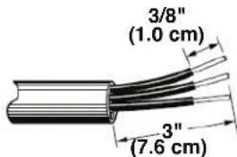
- Allow enough slack in the wire to easily attach the wiring terminal block.
- Complete installation following instructions for your type of electrical connection:
4-wire (recommended)
Electrical Connection Options
| Electrical Connection Options connecting to: | ||
| 4-wire direct 3/8" (1.0 cm) | A circuit breaker box or fused disconnect | 4-Wire Connection: Direct Wire |
| 5" (12.7 cm) | ||
4-Wire Connection: Direct Wire
Use this method for:
New branch-circuit installations (1996 NEC)
■ Mobile homes
Recreational vehicles
In an area where local codes prohibit grounding through the neutral
- Use a Phillips screwdriver to remove the ground-link screw from the back of the range. Save the ground-link screw and the end of the ground link under the screw.
- Pull the wires through the strain relief on bottom of range. Allow enough slack to easily attach wiring to the terminal block.
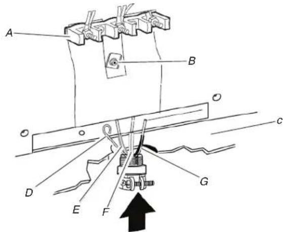
A. Terminal block
E. Line 2 (red) wire
B. Ground-link screw
F. Nautral (white) wire
G. Line 1 (black) wire
C. Cord/conduit
D. Bare (green) ground wire
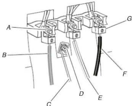
- Attach terminal lugs to line 1 (black), neutral (white), and line 7 (red) wires. Loosen (do not remove) the setscrew on the front of the terminal lug and insert exposed wire end through bottom of terminal lugs. Securely tighten setscrew to torque as shown in the following Bare Wire Torque Specifications chart.
A. Terminal lug
D. Natural (white) wire
B. Setscrew
E. Line 1 (black) wire
C. Line 2 (red) wire
Bare Wire Torque Specifications
Attaching terminal lugs to the terminal block - 20 lbs-in (2.3 N-m).
Wire Awg Torque
8 gauge copper 25 lbs-in (2.8 N-m)
6 gauge aluminium 35 lbs-in (4.0 N-m)
-
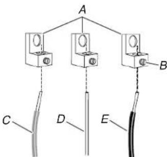
Use a hex or Phillips screwdriver to connect the bare (green) ground wire to the range with the ground-link screw and ground-link section. The ground wire must be attached over the ground-link section and must not contact any other terminal.
-
Use 3/8'' (1.0 cm) nut driver to connect the neutral (white) wire to the center terminal block post with one of the 10-32 hex nuts.
A. 10-32 hex nut E. Neutral (white) wire
B. Line 2 (red) wire F. Line 1 (black) wire
C. Bare (green) G. Terminal lug ground wire
D. Ground-link screw
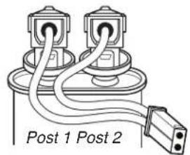
- Connect line 2 (red) and line 1 (black) wires to the outer terminal block posts with 10-32 hex nuts.
- Using a torque wrench, tighten the hex nuts to a recommended torque of 20 in-lbs (2.3 N-m).
- Firmly tighten hex nuts.
IMPORTANT: Verify the tightness of the hex nuts. Ensure all harnesses are tightened to the terminal block and are not loose.
- Replace lower access cover.
Make Gas Connection
WARNING
Explosion Hazard
Use a new CSA International approved gas supply Install a shut-off valve.
Securely tighten all gas connections.
If connected to propane, have a qualified person sure gas pressure does not exceed 14" (36 cm) column.
Examples of a qualified person include: licensed heating personnel, authorized gas company personnel, and authorized service personnel.
Failure to do so can result in death, explosion,
line.
make3
mater
This range is factory-set for use with Natural gas. To use this range with Propane gas, see the "Gas Conversions" section before connecting this range to the gas supply. Gas conversions from Natural gas to Propane gas or from Propane gas to Natural gas must be done by a qualified installer.
Typical Flexible Connection
- Apply pipe-joint compound made for use with Propane gas to the smaller thread ends of the flexible connector adapters. See B and G in the following illustration.
- Attach one adapter to the gas pressure regulator and the other adapter to the gas shutoff valve. Tighten both adapters being certain not to move or turn the gas pressure regulator.
- Use a 3/8'' (2.4 cm) combination wrench and an adjustable wrench to attach the flexible connector to the adapters.
IMPORTANT: All connections must be wrench-tightened. Do not make connections to the gas regulator too tight. Making the connections too tight may crack the regulator and cause a gas leak. Do not allow the regulator to turn when tightening fittings.
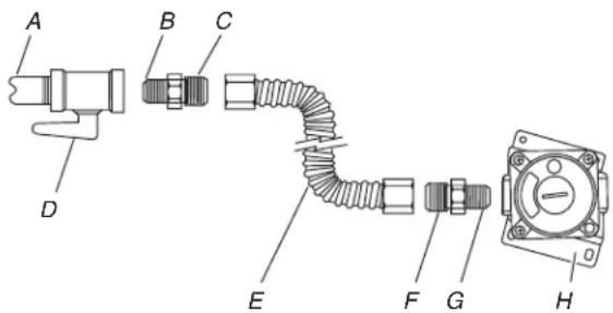
A. 1 / 2'' (1.3 cm) or 3 / 4'' (1.9 cm) gas pipe
E. Flexible connector
F. Adapter (must have 1/2'' [1.3cm] male pipe thread)
B. Use pipe-joint compound
G. Use pipe-joint compound H. Gas pressure regulator
C. Adapter
D. Manual gas shutoff valve
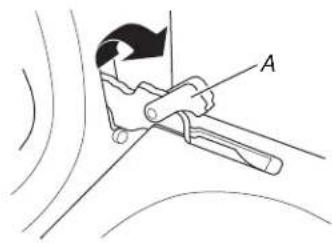
Complete Connection
- Open the manual shutoff valve in the gas supply line. The valve is open when the handle is parallel to the gas pipe.
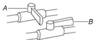
A. Closed Valve
B. Open Valve
- Test all connections by brushing on an approved noncorrosive leak-detection solution. If bubbles appear, a leak is indicated. Correct any leak found.
- Remove cooktop burner caps and bases from package containing parts. Place the burner bases as indicated below:
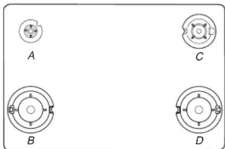
A. Small (Auxiliary)
B. Large (Ultra Rapid)
C. Medium (Semi Rapid)
D. Large (Ultra Rapid)
NOTE: Each round burner base is marked with one of the following: AUX, SR, or UR.
Align the gas tube opening in the burner base with the orifice holder on the cooktop and the igniter electrode with the notch in the burner base.

A. Burner cap
B. Gas tube opening
C. Burner base
D. Igniter electrode
E. Orifice holder
- Place the burner caps on the appropriate burner bases.
NOTE: The bottom of the small and medium caps are different. Do not put the wrong size burner cap on the burner base. Each round burner cap is marked with an AUX, SR, or UR to match with a letter on the burner base.
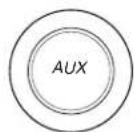
Small cap (Auxiliary)
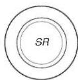
Medium cap (Semi Rapid)
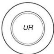
Large cap (Ultra Rapid)
Burner caps should be level when properly positioned. If burner caps are not properly positioned, surface burners will not light. The burner cap should not rock or wobble when properly aligned.
A. Incorrect
B. Correct
- Place burner grates over burners and caps.
- Plug into appropriate outlet. See the appropriate "Electrical Requirements" section.
- Turn on power.
Install Blower
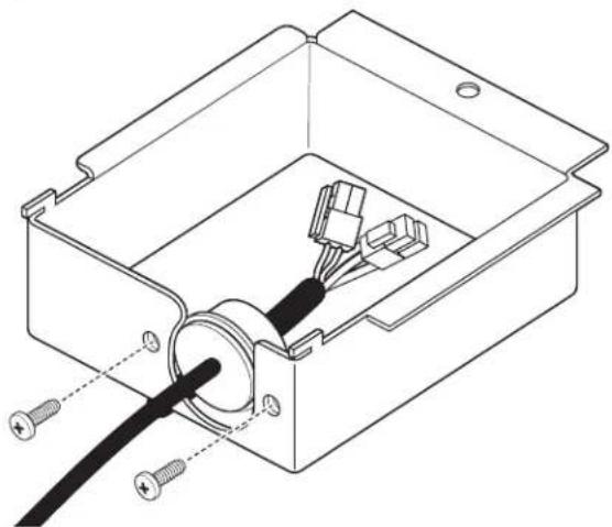
Install Blower Cover
- Locate blower motor cover.
- Run the blower motor wires with strain relief through the small opening in the blower motor cover, starting from the inside a feeding out.
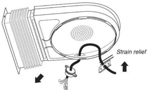
- Feed blower motor wire through opening and place the strain relief bracket to the inside of the blower cover. Install and tighten the two (2) provided #8-18 x 3/8" screws to secure the strain relief bracket.
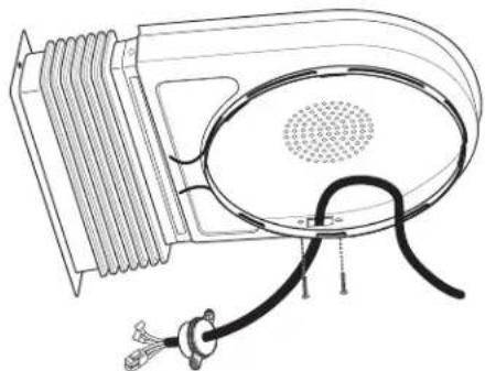
- Reposition the blower motor cover retainer spring as illustrated.
- Remove paper from the rear of the rectangular felt pad and apply adhesive side of felt to the bellow flange.
NOTE: This step is important to ensure maximum blower performance.
Apply blower motor cover to the blower. Slightly spread the cover retainer spring to allow the cover to drop into position on the blower motor.
NOTE: The blower motor cover will not properly install if the motor wire is on the top of the motor.
Incorrect correct
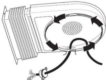
- Rotate blower motor cover so the bellows are facing towards 15. Secure the front of the blower bellow flange to the range frame the front of the installation. with the supplied #8-18 x 3/8" screw.
- Move blower motor wire to the front of the installation.
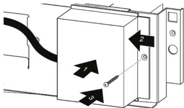
- Remove the cardboard or hardboard from under the range.
- Remove the front lower access panel of the range by gently lifting on the panel then pull outward.
- Using 2 or more people, gently move the range into its final location.
- Check to ensure the flexible metal gas connector and electrical cord are not kinked. Use a flashlight to look underneath the bottom of and behind the range.
- Verify that the anti-tip bracket is installed and engaged.
Use a flashlight to look underneath the bottom of and behind the range.
Visually check that the rear range foot is inserted into the slot of the anti-tip bracket.

- Rotate blower motor cover so the bellows are in their final position. Ensure the rear of the bellow flange is engaged in the retaining bracket.
A. Retaining bracket
Final Position
A. Screw
Connect Blower Electrical Parts
- Locate the capacitor (in Blower Motor Kit).
NOTE: The capacitor is supplied with a small harness that terminates in a two-pin connector as shown.
Locate the capacitor storage tray in front of the blower bellow connection point in the lower right side of the range.
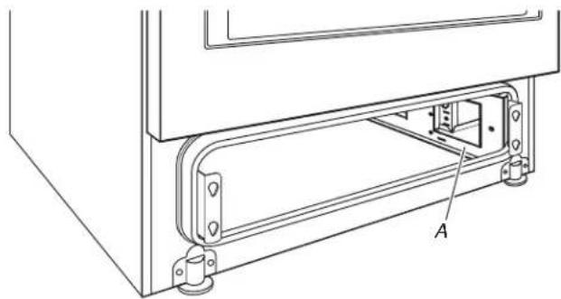
A. Capacitor storage tray
- Place capacitor in tray.
- Secure the capacitor with the capacitor retention bracket, then install the bracket screw.
A. Retention bracket
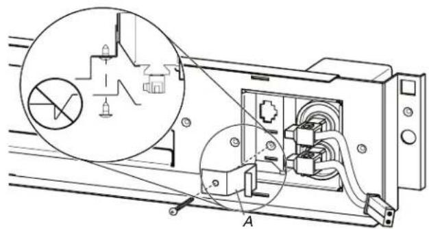
- Secure the blower motor strain relief, near the quick 9. connection end, to the blower electrical terminal cover with the two provided screws.
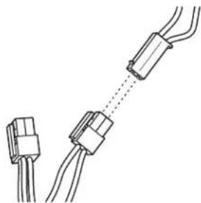
- Locate the two-pin connector on the blower motor wire harness and connect it to the two-pin capacitor connector.
- Install terminal cover screw.
- Replace the access panel by aligning the studs with the keyhole slots on the range. Press the access panel forward into the slots and push downward to engage the studs.
- Locate the 4-pin connector on the blower motor wire and plug1. Reconnect power. It into the terminal connection point directly behind the capacitor storage tray. NOTE: The terminal release (clip point) will be facing toward the front of the range.
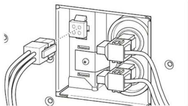
- Install blower electrical terminal cover. NOTE: When replacing cover, insert the terminal cover tabs in the corresponding slots in the range, and push the terminal cover rearward to engage.
Verify Anti-Tip Bracket Is Installed and Engaged
Electronic Ignition System
Initial Lighting and Gas Flame Adjustments
Cooktop and oven burners use electronic igniters in place of standing pilots. When the cooktop control knob is turned to the ignite position, the system creates a spark to light the burner. All cooktop burners will spark, but only the burner with the control knob turned to the ignite position will produce a flame. This sparking continues as long as the control knob is turned to the ignite position.
On Ranges Equipped with a Premium Storage Printer:
- Slide range into final location, making sure rear leveling leg slides into anti-tip bracket.
- Remove the premium storage drawer. See the "Remove/ReplaceDrawer" section.
- Use a flashlight to look underneath the bottom of the range.
- Visually check that the rear range foot is inserted into the s of the anti-tip bracket.
On Ranges Equipped with a Warming Printer or Baking Printer:
- Slide range into final location, making sure rear leveling leg slides into anti-tip bracket. Leave a 1" (2.5 cm) gap between the back of the range and the back wall.
- Place the outside of your foot against the bottom front of the warming drawer or baking drawer to keep the range from moving, and then grasp the back of the range, as shown.
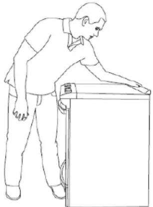
- Slowly attempt to tilt the range forward.
If you encounter immediate resistance, the range foot is engaged in the anti-tip bracket. Go to Step 8.
- If the rear of the range lifts more than 1/2 (1.3 cm) off the floor without resistance, stop tilting the range and lower it gently back to the floor. The range foot is not engaged in the anti-tip bracket.
Check Operation of Cooktop Burners
Standard Surface Burners
Push in and turn each control knob to the ignite position.
The flame should light within 4 seconds. The first time a burner is lit, it may take longer than 4 seconds to light because of air in the gas line.
If Burners Do Not Light Properly:
Turn cooktop control knob to the off position.
- Check that the range is plugged into a grounded 3 prong outlet. Check that the circuit breaker has not tripped or the household fuse has not blown.
- Check that the gas shutoff valves are set to the open position.
- Check that burner caps are properly positioned on burner bases.
A. Incorrect
B. Correct
IMPORTANT: If there is a snapping or popping sound when lifting the range, the range may not be fully engaged in the bracket. Check to see if there are obstructions keeping the range from sliding to the wall or keeping the range foot from sliding into the bracket. Verify that the bracket is held securely in place by the mounting screws. If the cooktop "low" burner flame needs to be adjusted for any of
- Slide the range forward, and verify that the anti-tip bracket is securely attached to the floor or wall.
- Slide range back so the rear range foot is inserted into the of the anti-tip bracket.
- Repeat steps 1 and 2 to ensure that the range foot is engaged in the anti-tip bracket.
If the rear of the range lifts more than 1/2 (1.3 cm) off the floor without resistance, the anti-tip bracket may not be installed correctly. Do not operate the range without anti-tip bracket installed and engaged. Please reference the "Warranty" to contact service.
- Move the range into its final location. Check that the range is level by placing a level on the oven bottom. See the "Level Range" section.
IMPORTANT: If the range is moved to adjust the leveling legs, verify that the anti-tip bracket is engaged by repeating steps 1 to 8.
In case of prolonged power failure, the surface burners can be lit manually. Hold a lit match near a burner, and then turn knob counterclockwise to LITE. After burner lights, turn knob to desired setting.
Remove/Replace Drawer (on some Oven Door models) For normal range use door However if no
Remove all items from inside the baking drawer, and then allow the range to cool completely before attempting to remove the drawer.
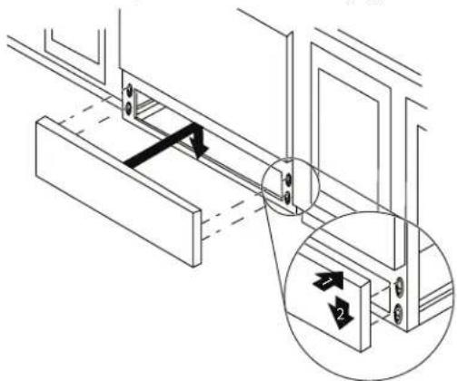
To Remove:
- Open the drawer to its fully open position.
- Using a flat-blade screwdriver, gently loosen the drawer from the glide alignment notch, and then lift up the drawer alignment tab from the glide.
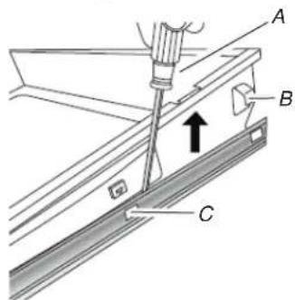
A. Flat-blade screwdriver
B. Drawer alignment tab
C. Drawer glide notch
- Repeat Step 2 on the other side. The drawer is no longer attached to the drawer glides. Using both hands, pick up the drawer to complete the removal.
To Replace:
- Align the forward drawer notches with the notches in the drawer glides on both sides. Place the rear alignment tabs into the drawer glides on both sides.
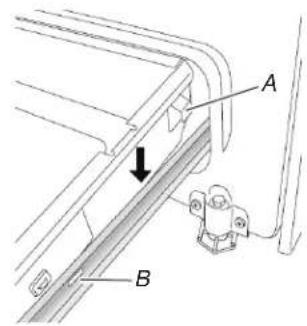
A. Drawer alignment tab
B. Drawer glide notch
- Push the drawer in all the way.
- Gently open and close the drawer to ensure it is seated properly on the glides on both sides.
For normal range use, it is not suggested to remove the oven door. However, if removal is necessary, make sure the oven is off and cool. Then, follow these instructions. The oven door is heavy.
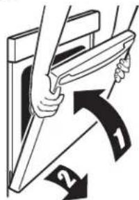
To Remove:
- Open oven door all the way.
- Pinch the hinge latch between two fingers and pull forward. Repeat on other side of oven door.
A. Hinge latch
- Close the oven door as far as it will shut.
- Lift the oven door while holding both sides.
Continue to push the oven door closed and pull it away from the oven door frame.
To Replace
- Insert both hanger arms into the door. Be sure that the hinge notches are engaged in the oven door frame.
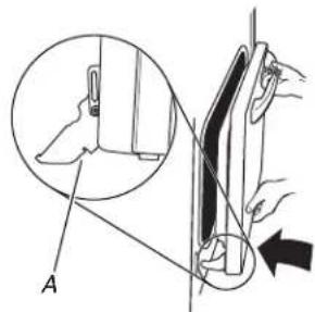
A. Hinge latch
- Open the oven door.
The door should be able to open all the way. - Move the hinge levers back to the locked position. Check that the door is free to open and close and is level while closed. If it is not, repeat the removal and installation procedures.
Complete Installation
- Check that all parts are now installed. If there is an extra go back through the steps to see which step was skipped
- Check that you have all of your tools.
- Check that you have all of the range accessories, especially oven racks. These accessories may be in the range packaging.
- Dispose of/recycle all packaging materials.
- Check that the range is level. See the "Level Range" section.
- Use a mild solution of liquid household cleaner and warm water to remove waxy residue caused by shipping material. Dry thoroughly with a soft cloth. For more information, see the "Range Maintenance and Care" section.
- Read the Quick Start Guide and online Control Guide.
- Turn on surface burners and oven. See the Quick Start Guide and online Control Guide for specific instructions on range operation. NOTE: Odors and smoke are normal when the oven is used the first few times.
If Range Does Not Operate, Check the Following:
Household fuse is intact and tight, or circuit breaker has not tripped.
Gas pressure regulator shutoff valve is in the open position.
- Range is plugged into a grounded outlet.
- Electrical supply is connected.
IMPORTANT: If the range control displays an "F9" or "F9 E0" error code, the electrical outlet in the home may be miswired. Disconnect power and contact a qualified electrician to verify the electrical supply.
- When the range has been on for 5 minutes, check for heat. the range is cold, turn off the range and check that the gas supply line shutoff valve is open.
If the gas supply line shutoff valve is closed, open it, and then repeat the 5 minute test as outlined above.
If the gas supply line shutoff valve is open, close it, and contact a qualified technician.
If You Need Assistance or Service:
Please refer the Quick Start Guide for contact information.
GAS CONVERSIONS
Gas conversions from Natural gas to propane gas or from propane gas to Natural gas must be done by a qualified installer.
WARNING
Explosion Hazard
Use a new CSA International approved gas supply line. Install a shut-off valve.
Securely tighten all gas connections.
If connected to propane, have a qualified person make sure gas pressure does not exceed 14" (36 cm) water column.
Examples of a qualified person include: licensed heating personnel, authorized gas company personnel, and authorized service personnel.
Failure to do so can result in death, explosion, or fire.

WARNING:
If This conversion kit shall be installed by a qualified service agency in accordance with the manufacturer's instructions and all applicable codes and requirements of the authority having jurisdiction. If the information in these instructions is not followed exactly, a fire, an explosion or production of carbon monoxide may result causing property damage, personal injury or loss of life. The qualified service agency is responsible for the proper installation of this kit. The installation is not proper and complete until the operation of the converted appliance is checked as specified in the manufacturer's instructions supplied with the kit.
Propane Gas Conversion
AWARNING

Tip Over Hazard
A child or adult can tip the range and be killed.
Install anti-tip bracket to floor or wall per installation instructions.
Slide range back so rear range foot is engaged in slot of the anti-tip bracket.
Re-engage anti-tip bracket if range is moved.
Do not operate range without anti-tip bracket installed and engaged.
Failure to follow these instructions can result in death or serious burns to children and adults.
- Turn manual shutoff valve to the closed position.
A. To range
B.Shutoff valve (closed position)
C. Gas supply line
- Unplug range or disconnect power.
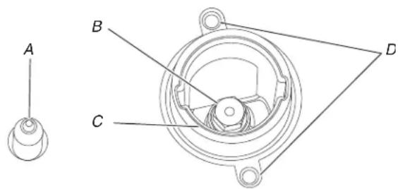
To Convert Gas Pressure Regulator (Natural to Propane Gas)
- Move the range out about 1 ft (30.5 cm) from the wall.
- Locate the gas pressure regulator at the lower right corner on the back of the range.
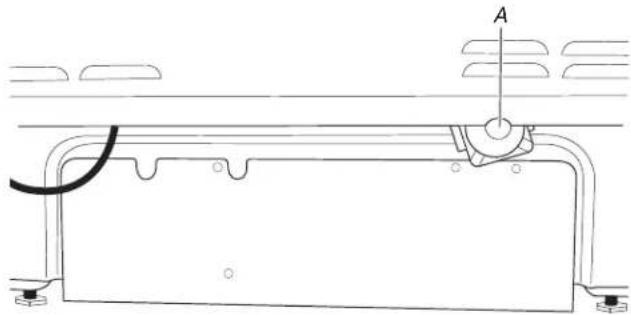
A. Gas pressure regulator
IMPORTANT: Do not remove the gas pressure regulator.
- Unscrew the metal cover and unscrew the blue regulator cap. Keep the washer in place.
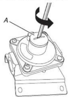
A. Metal cover
B. Washer
C. Blue regulator cap
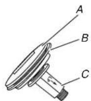
- Flip the blue regulator cap over and screw it back into the metal cover.
A. Natural gas position
B. Propane gas position
- Screw the metal cover securely back into place. Do not overtighten.
To Convert Surface Burners (Natural Gas to Propane Gas)
As 1. If installed, remove the burner grates.
2. Remove the burner caps.
3. Remove the burner base.
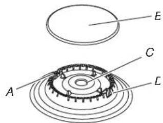
A. Igniter electrode
B. Bumer cap
C. Gas tube opening
D. Burner base
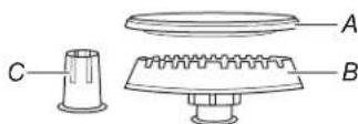
Large Burner
A. Bumer cap
B. Burner base
C. Choke (for use with large burner, Propane gas only)
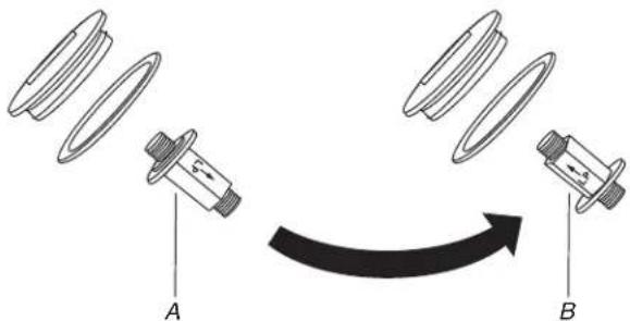
- Apply masking tape to the end of a 9/32'' (7 mm) nut driver help hold the gas orifice spud in the nut driver while changing it. Press nut driver down onto the gas orifice spud and remove by turning it counterclockwise and lifting out. Set gas orifice 1 spud aside.
A. Igniter electrode
B. Orifice spud
C. Orifice spud holder
D. Screws
Complete Installation (Natural Gas to Propane Gas)
Refer to the "Make Gas Connection" section for proper connection of the range to the gas supply.
- Refer to the "Electronic Ignition System" section for proper burner ignition and operation.
- Refer to the "Adjust Flame Height" section for burner flame adjustments.
IMPORTANT: You may have to adjust the low setting for each cooktop burner.
Checking for proper cooktop burner flame is very important. Natural gas flames do not have yellow tips.
- Refer to "Complete Installation" in the "Installation Instructions" section of this manual to complete this procedure.
IMPORTANT: Make sure to save the orifices that have just been replaced in the conversion.
- Remove the orifice spuds shipped in the literature package in the oven. Gas orifice spuds are stamped with a number, marked with 1 or 2 color dots, and have a groove in the he area. Replace the Natural gas orifice spud with the correct Propane gas orifice spud.
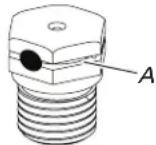
A. Propane groove
Refer to the following chart for correct Propane gas orifice spud ratings and to spud holder card for proper placement. Fully insert choke into bottom of large burner base. Choke should snap into place.
NOTE: Use only for speader bases marked "L".
Propane Gas Orifice Spud Chart for Surface Burners.
| Placement | Burner Rating/Type | Size (mm) | ID | Number |
| LF (ST) | 15,000 BTU 1.08 108AM | |||
| 1,450 BTU 0.35 035AM | ||||
| LR 5,000 BTU 0.64 064AM | ||||
| RF 14,200 BTU 1.08 108AM | ||||
| RR 8,000 BTU 0.84 084AM | ||||
| CTR 8,000 BTU 0.84 084AM | ||||
NOTE: Refer to the model/serial/rating plate located on the oven frame behind the top right-hand side of the oven door for proper sizing of spuds for each burner location.
- Place Natural gas orifice spuds in the orifice spud bag.
IMPORTANT: Keep the Natural gas orifice spuds in case of reinstallation with Natural gas.
- Replace the burner base.
- Replace burner cap.
- Repeat steps 1 to 7 for the remaining burners.
- Replace the baking drawer. See the "Remove/ReplaceDrawer" section.
Natural Gas Conversion
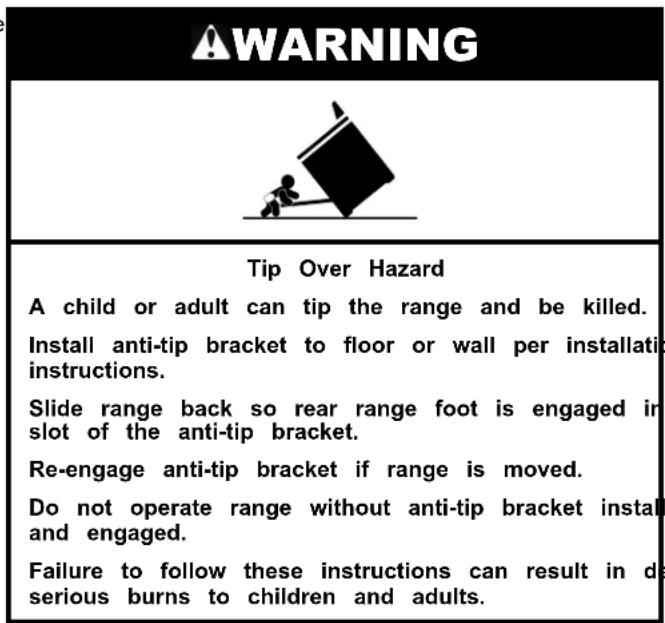
- Turn manual shutoff valve to the closed position.
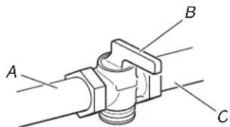
A. To range
B.Shutoff valve (closed position)
C. Gas supply line
- Unplug range or disconnect power.
To Convert Gas Pressure Regulator (Propane to Natural Gas)
- Move the range out about 1 ft (30.5 cm) from the wall.
- Locate the gas pressure regulator at the lower right corner the back of the range.
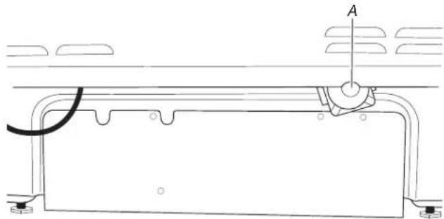
A. Gas pressure regulator
IMPORTANT: Do not remove the gas pressure regulator.
- Unscrew the metal cover and unscrew the blue regulator cap. Keep the washer in place.
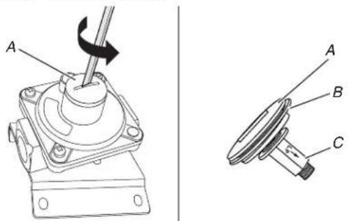
A. Metal cover
B.Washer
C. Blue regulator cap
- Flip the blue regulator cap over and screw it back into the metal cover.
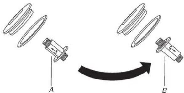
A. Propane gas position
B. Natural gas position
- Screw the metal cover securely back into place. Do not overtighten.
Gas Convert Surface Burners (Propane Gas to Natural Gas)
- If they are installed, remove the burner grates.
- Remove the burner caps.
- Remove the burner base.
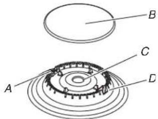
A. Igniter electrode
B. Bumer cap
C. Gas tube opening
D. Bumer base
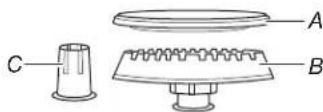
Large Burner
A. Bumer cap
B. Burner base
C. Choke (for use with large burner, Propane gas only)
- Apply masking tape to the end of a 9/32'' (7 mm) nut driver to help hold the gas orifice spud in the nut driver while changing it. Press nut driver down onto the gas orifice spud and remove by turning it counterclockwise and lifting out. Set gas orifice spud aside.
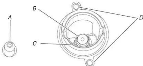
A. Igniter electrode
B. Orifice spud
C. Orifice spud holder
D. Screws
- Remove the orifice spuds shipped in the literature package the oven. Gas orifice spuds are stamped with a number, marked with 1 or 2 color dots, and have a groove in the area. Replace the Natural gas orifice spud with the correct Propane gas orifice spud.
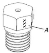
A. Stamped number
Refer to the following chart for the correct Natural gas orifice spud placement. Remove choke from large burner base.
Natural Gas Orifice Spud Chart
| Burner Rating Size (mm) ID Number |
| 19,000 BTU (ST) 1.96 196AM |
| 17,000 BTU (ST) 1.84 184AM |
| 18,000 BTU 1.98 198AM |
| 17,000 BTU 1.96 196AM |
| 15,000 BTU 1.75 175AM |
| 9,200 BTU 1.35 135AM |
| 8,000 BTU 1.25 125AM |
| 5,000 BTU 1.00 100AM |
| 1,450 BTU 0.53 053AM |
NOTE: Refer to the model/serial/rating plate located on the oven frame behind the top right-hand side of the oven door for proper sizing of spuds for each burner location.
- Place Propane gas orifice spuds in the orifice spud bag.
IMPORTANT: Keep the Propane gas orifice spuds in case of reinstallation with Propane gas.
- Replace the burner base.
- Replace burner cap.
- Repeat steps 1 to 7 for the remaining burners.
- Replace the baking drawer. See the "Remove/ReplaceDrawer" section.
Complete Installation (Propane Gas to Natural Gas)
- Refer to the "Make Gas Connection" section for proper connection of the range to the gas supply.
- Refer to the "Electronic Ignition System" section for proper burner ignition and operation.
- Refer to the "Adjust Flame Height" section for burner flame adjustments.
IMPORTANT: You may have to adjust the low setting for each cooktop burner.
Checking for proper cooktop burner flame is very important. Natural gas flames do not have yellow tips.
- Refer to "Complete Installation" in the "Installation Instructions" section of this manual to complete this procedure.
IMPORTANT: Make sure to save the orifices that have just been replaced in the conversion.
Adjust Flame Height Adjust Surface Burner Flame
Adjust the height of top burner flames. The cooktop "low" burner flame should be a steady blue flame approximately 1/4 (6 mm) high. Propane gas flames have a slightly yellow tip.
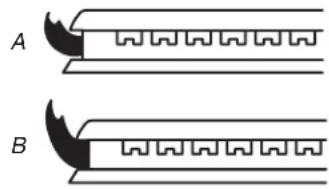
A. Low flame
B. High flame
To Adjust Standard Burner:
The flame can be adjusted using the adjustment screw in the center of the valve stem. The valve stem is located directly underneath the control knob.
If the "Low" Flame Needs to be Adjusted:
- Light 1 burner and turn to lowest setting.
- Remove the control knob.
Hold the knob stem with a pair of pliers. Use a small flat-blade screwdriver to turn the screw located in the center of the control knob stem until the flame is the proper size. Turning the screw clockwise will increase the flame size, and turning the screw counterclockwise will decrease the flame size.
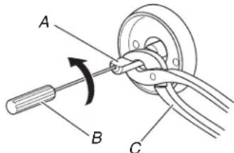
A. Control knob stem
B. Screwdriver
C. Pliers
- Replace the control knob.
- Test the flame by turning the control from the low position to the high position, checking the flame at each setting.
- Repeat the previous steps for each burner.
To Adjust Double Burner (On Some Models):
- Light burner and turn to lowest setting where both inner and outer burners are lit.
- Remove the control knob.
Hold the knob stem with a pair of pliers. Use a small flat-blade screwdriver to turn the screw located in the center of the control knob stem until the flame is the proper size. Turning the screw clockwise will increase the flame size, and turning the screw counterclockwise will decrease the flame size.
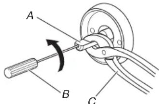
A. Control knob stem
B. Screwdriver
C. Pliers
- Replace the control knob.
- Test the flame by turning the control from the low position to the high position, checking the flame at each setting.
Moving the Range
AWARNING

Tip Over Hazard
A child or adult can tip the range and be killed. Install anti-tip bracket to floor or wall per installation instructions.
Slide range back so rear range foot is engaged in slot of the anti-tip bracket.
Re-engage anti-tip bracket if range is moved.
Do not operate range without anti-tip bracket installed and engaged.
Failure to follow these instructions can result in death serious burns to children and adults.
When moving range, slide range onto cardboard or hardboard to avoid damaging the floor covering.
If removing the range is necessary for cleaning or maintenance:
For power supply cord-connected ranges:
- Slide range forward.
- Turn manual shutoff valve to the closed position.
- Unplug the power supply cord.
- Disconnect the gas supply tubing.
- Complete cleaning or maintenance.
- Reconnect the gas supply tubing.
- Open the manual shutoff valve in the gas supply line.
- Test for leaks using method described in "Make Gas Connection" section.
- Plug in power supply cord.
- Slide range back so rear range foot is under anti-tip bracket.
- Refer to the "Verify Anti-Tip Bracket Is Installed and Engaged" section to verify engagement.
- Check that range is level.
For direct-wired ranges:
AWARNING

Electrical Shock Hazard
Disconnect power before servicing.
Replace all parts and panels before operating.
Failure to do so can result in death or electrical
shock.
- Disconnect power.
- Slide range forward.
- Turn manual shutoff valve to the closed position.
- Disconnect the gas supply tubing.
- Complete cleaning or maintenance.
- Reconnect the gas supply tubing.
- Open the manual shutoff valve in the gas supply line.
- Test for leaks using method described in "Make Gas Connection" section.
- Check that the anti-tip bracket is installed and engaged. See or the "Verify Anti-Tip Bracket Is Installed and Engaged" section.
- Check that range is level.
- Reconnect power.
SECURITE DE LA CUISINIÈRE
AVENTISSEMENT
AquaLift® Self-Cleaning Technology
National Fire Protection Association
1 BatteryMarch Park
Quincy, MA 02169-7471
Toronto, ON M9W 1R3 CANADA
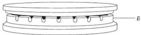
A. Incorrect B. Correct
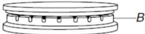
A. Incorrect B. Correct

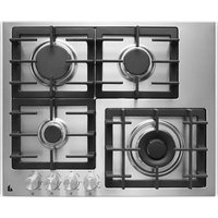
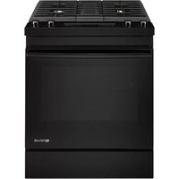
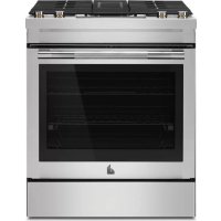
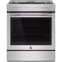
- SLIDE-IN DUAL-FUEL DOWNDRAFT RANGE
- OWNER'S MANUAL
- MANUEL D'UTILISATION DE LA CUISINIÈRE À
- DOUBLE COMBUSTIBLE ENCASTRÉE À ÉVACUATION
- PAR LE BAS
- Table of Contents/Table des matieres
- IMPORTANT :
- WARNING:
- AWARNING
- Your safety and the safety of others are very important.
- ADANGER
- WARNING
- IMPORTANT SAFETY INSTRUCTIONS
- SAVE THESE INSTRUCTIONS
- For self-cleaning ranges
- For units with ventilating hood
- For smart enabled ranges and ovens
- RANGE MAINTENANCE AND CARE
- AquaLift®
- Self-Cleaning Technology
- To Clean:
- NOTE:
- General Cleaning
- EXTERIOR PORCELAIN ENAMEL SURFACES (on some models)
- Cleaning Method:
- STAINLESS STEEL (on some models)
- Yellow Heat Stains:
- METALLIC PAINT (on some models)
- PORCELAIN-COATED GRATES AND CAPS
- SURFACE BURNERS
- COOKTOP CONTROLS
- GRIDDLE (on some models)
- CONTROL PANEL AND OVEN DOOR EXTERIOR
- OVEN RACKS
- BAKING DRAWER (on some models)
- STORAGE/WARMING DRAWER (on some models)
- OVEN CAVITY
- Downdraft ventilation system
- Vent Grade
- Filter
- Ventilation Chamber
- INSTALLATION INSTRUCTIONS REQUIREMENTS
- Tools and Parts
- Tools needed
- For Propane/Natural Gas Conversions
- Parts supplied
- Parts Needed
- Optional Parts
- Location Requirements
- Mobile Home - Additional Installation Requirements
- Mobile Home Installations Require:
- Cabinet Dimensions
- Venting Requirements
- For Best Performance:
- Cold Weather Installations
- Makeup Air
- Venting Methods
- Wall Venting
- Floor Venting
- Calculating Vent System Length
- Electrical Requirements - U.S.A. Only
- Electrical Connection
- Electrical Requirements - Canada Only
- Gas Supply Requirements
- Explosion Hazard
- Type of Gas
- Natural Gas:
- Propane Gas Conversion:
- Gas Supply Line
- Flexible metal appliance connector:
- Gas Pressure Regulator
- Propane gas:
- Burner Input Requirements
- Gas Supply Pressure Testing
- INSTALLATION
- Unpack Range
- Install Anti-Tip Bracket
- Tip Over Hazard
- Floor Mounting
- Wall Mounting
- Position the Blower Location Template
- Install the Downdraft System
- Rear Wall Venting
- Adjust Leveling Legs
- Level Range
- Electrical Connection - U.S.A. Only
- Direct Wire Strain Relief
- Direct Wire Installation: Copper or Aluminum Wire
- 4-Wire Connection: Direct Wire
- Bare Wire Torque Specifications
- Wire Awg Torque
- Make Gas Connection
- Typical Flexible Connection
- Complete Connection
- Install Blower
- Install Blower Cover
- Connect Blower Electrical Parts
- Verify Anti-Tip Bracket Is Installed and Engaged
- Electronic Ignition System
- On Ranges Equipped with a Warming Printer or Baking Printer:
- Check Operation of Cooktop Burners
- Standard Surface Burners
- Remove/Replace Drawer (on some Oven Door models) For normal range use door However if no
- To Remove:
- To Replace:
- To Replace
- Complete Installation
- If You Need Assistance or Service:
- GAS CONVERSIONS
- Propane Gas Conversion
- To Convert Gas Pressure Regulator (Natural to Propane Gas)
- To Convert Surface Burners (Natural Gas to Propane Gas)
- Complete Installation (Natural Gas to Propane Gas)
- Natural Gas Conversion
- To Convert Gas Pressure Regulator (Propane to Natural Gas)
- Gas Convert Surface Burners (Propane Gas to Natural Gas)
- Large Burner
- Complete Installation (Propane Gas to Natural Gas)
- Adjust Flame Height Adjust Surface Burner Flame
- To Adjust Standard Burner:
- If the "Low" Flame Needs to be Adjusted:
- To Adjust Double Burner (On Some Models):
- Moving the Range
- For power supply cord-connected ranges:
- Electrical Shock Hazard
- SECURITE DE LA CUISINIÈRE
- AVENTISSEMENT
- AquaLift® Self-Cleaning Technology
Brand : JENN-AIR
Model : JDS1450ML
Category : Cooker