VK 1099/370 - Surveillance Camera GROTHE - Free user manual and instructions
Find the device manual for free VK 1099/370 GROTHE in PDF.


User questions about VK 1099/370 GROTHE
0 question about this device. Answer the ones you know or ask your own.
Ask a new question about this device
Download the instructions for your Surveillance Camera in PDF format for free! Find your manual VK 1099/370 - GROTHE and take your electronic device back in hand. On this page are published all the documents necessary for the use of your device. VK 1099/370 by GROTHE.
USER MANUAL VK 1099/370 GROTHE
natural_image
White surveillance camera icon on light blue background (no text or symbols)IT | EN | FR | DE
www.urmet.com
Guida rapida
H.265 IP CAMERA SERIES
INDICE
INDICE....2
text_image
Slot SD card Slot SD cardnatural_image
Diagram of a mechanical component with a wheel and textured surface (no text or symbols)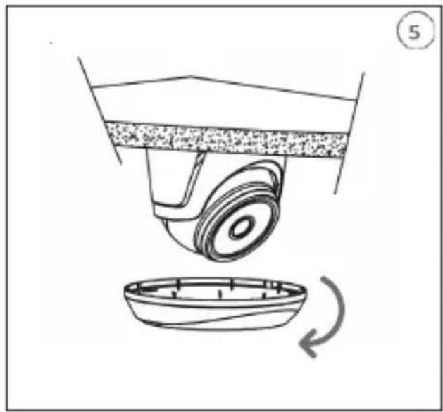
natural_image
Diagram of a mechanical device with a rotating base and a curved component, no text or symbols present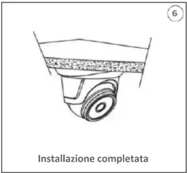
text_image
Set SD cardtext_image
3 Calottanatural_image
Close-up of a mechanical device with a red arrow pointing to a component (no visible text or symbols)natural_image
Technical line drawing of a mechanical assembly with gears and housing (no text or symbols)Slot SD card
TELECAMERA PTZ 4K 4X DETERRENCE
text_image
Reset Slot Micro SD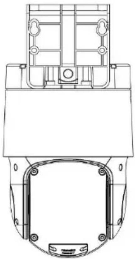
natural_image
Technical line drawing of a mechanical component with mounting holes and structural brackets (no text or symbols)INSTALLAZIONE TELECAMERA SPEED DOME IP 25X-33X
Fissaggio a parete
text_image
Dima Parete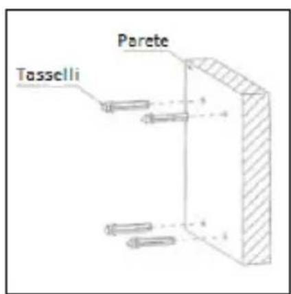
text_image
Tasselli Parete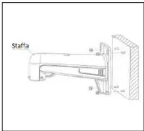
text_image
Staffa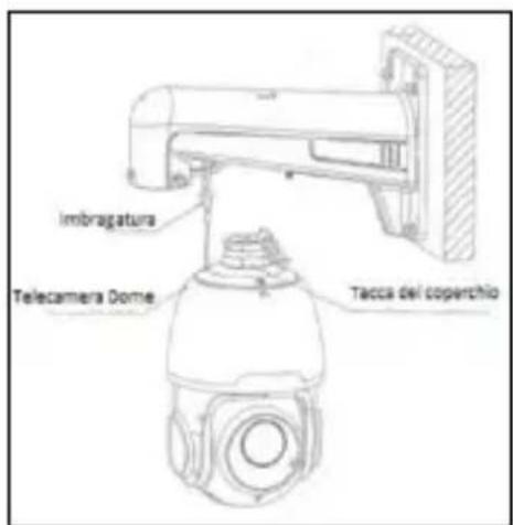
text_image
Imbragatura Telecamera Dome Tacca del coperchio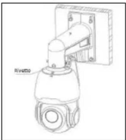
text_image
Rivotto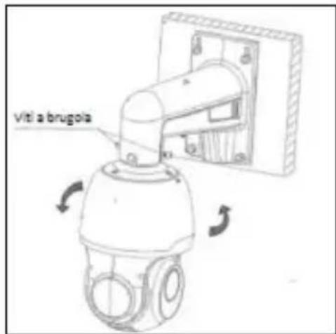
text_image
Viti a brugolatext_image
User Info Username admin Password ***** Device Info Start IP Media Port Web Port Gateway Net Mask Net Mode Static Modifytext_image
You haven't installed the plugin or it is not the latest version. Please click download to download the latest plugin. Please close browser before plugin installation!!! Configure browser PC, Web plugin.exe (145 MHz, do 902.148.3.112!text_image
Setup - WebPlugin Ready to Install Setup is now ready to begin installing WebPlugin on your computer. Click Install to continue with the installation. Install Canceltext_image
Password New Password ? Password cannot be empty! Password Strength Confirm Password OKtext_image
Recover Password □ Security Question Comparative Security Question 1 Your self-avend? Answer Security Question 2 Your members name? Answer security question 3 Your next problem's name is better high school? Answer □ Certificate of authorization □ Super code(Not recommended) OK Canceltext_image
Information Password changed successfully! OKThank you for purchasing this product.
This quick start guide was written to help you set up H.265 IP Camera Series rapidly and easily.
Read this quick start guide which contains information for correct, safe use carefully before using the device.
Keep this guide at hand so that you can refer to it when needed.
*NOTE
For more detailed information about the devices, refer to the complete user manual available on the Urmet website (see QR code printed on the Addendum sheet).
WARNINGS
Electricity
Before connecting to electrical outlet, verify the electrical specifications of the device are suitable for the available power source.
We suggest to connect the device to electrical outlet via a switch disconnector.
In case of malfunctioning, disconnect electrical power from the general switch.
Use only the provided power supply.
Safety precautions
Do not expose the device to rain or humidity and do not insert any solid or liquid object in it to prevent the risk of fire or electrocution. In these events disconnect the device from the electrical outlet and call technical assistance to check it.
Do not open the device. Any repair must be made by qualified personnel or by calling the nearest authorized technical assistance center (www.urmet.com >> Contacts).
Keep the device away from children to prevent any, even involuntary, damaging.
Do not touch the device with wet hands as it might cause electrical shock or mechanical damages.
If the device falls down while working or if the salesbox is damaged, do not continue using it. If usage is continued under such circumstances electrical shocks might take place.
Contact the authorized retailer or installer.
Installation precautions
Before installing the camera, check its technical specifications to ensure that the IP rating is suitable for the environment in which it will be mounted. The IP rating is only guaranteed if the product is installed correctly.
Do not point the camera directly to sunlight or other intense sources of light, even when turned off. The subject of recording must not be against the light.
Do not point the camera against reflective objects.
Some light conditions (such as fluorescent color) can affect the recorded colors. Use AUTO-IRIS lens when operating the camera in changing light environments.
Do not use this device on any unstable support such as lurching or sloping table to prevent the device from falling and be damaged.
If water or any other material should penetrate the camera, stop using it as it might cause fire or electrical shock and contact the authorized retailer or installer.
Do not cover the device with any cloth while using to prevent deformation of the external part and inner components heating which might provoke fire, electrical shock or mechanical damages.
Do not put magnets or magnetized objects close to the device to prevent functional anomalies.
Do not use this device in presence of smoke, steam, humidity, dust or intense vibrations. Do not use the device shortly after moving it from warm to cold environment and vice versa. After moving the device wait three hours before using it: this time is necessary for the device to adapt to the new environment (temperature, humidity, etc.).
Usage precautions
Check the device is not damaged after removing the packaging.
Check the working environment is not too humid and the temperature is within the indicated range.
Do not point the camera against sunlight to prevent sensor damages.
Device cleaning
Use a dry cloth to remove dust and dirt from the device.
If dirt cannot be removed with a dry cloth, use a humid cloth and a neutral cleanser.
Do not use spray cleanser for device cleaning. Do not use volatile liquids such as gasoline, alcohol, solvents etc. or chemical treated cloth to clean the device to prevent deformations, damages or scars on the finishing paint.
Disconnect the device from the electrical outlet before cleaning.
Video recording
This device is not designed as a burglar system but mainly to transmit and record video images. URMET S.p.A. is not in any way responsible for loss or damages of the user consequent to theft.
Before using the device, record a demo video to verify the correct functionality of this feature. URMET S.p.A. is not in any way responsible for loss of recorded data consequent to wrong setting or usage, device malfunctioning or failure.
This device is composed by electronic precision components. Do not hit the device while recording as it might affect the video.
Privacy and Copyright
The IP camera is designed for surveillance systems. Video recording is subject to the laws applicable to the Country where used. It is forbidden to record images with Copyright.
The User is responsible to check and respect all local laws and norms for video signal recording. The manufacturer is NOT in any way liable for any usage of the product
which might result not compliant to the relevant norms.
Firmware upgrade
Periodically check the Urmet website in the product-specific section for software and/or firmware updates (go to www.urmet.com in the Products section "CCTV-VIDEOSURVEILLANCE", type the reference product code in the search field and move to DOCUMENTATION AND RESOURCES).
Network configuration
Camera default setting is DHCP mode. If the network does not support dynamic addressing (DHCP), the device will automatically switch to factory IP 192.168.1.168. Use Urmet "Device Config. Tool" software in order to modify the IP address and other network settings to prevent any conflict with other devices on the network.
Network connections
When connecting a PC (using Software Client or Browser), any video channel on the PC will be using "unicast" connection (TCP, RTP, UDP).
The device can support up to 10 "unicast" connections so it is possible to show the video on maximum 10 remote devices (PC or smartphone) at the same time depending on the available network band.
Installation
INSTALLATION OF BULLET CAMERAS
Ceiling Mounting
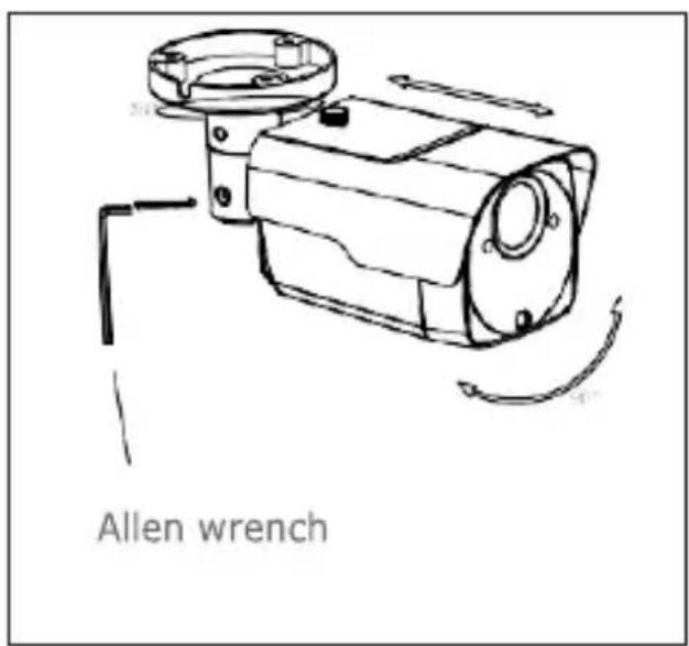
Insert three expansion bolts in place into the ceiling and fix the equipment with three locking screws
text_image
Allen wrench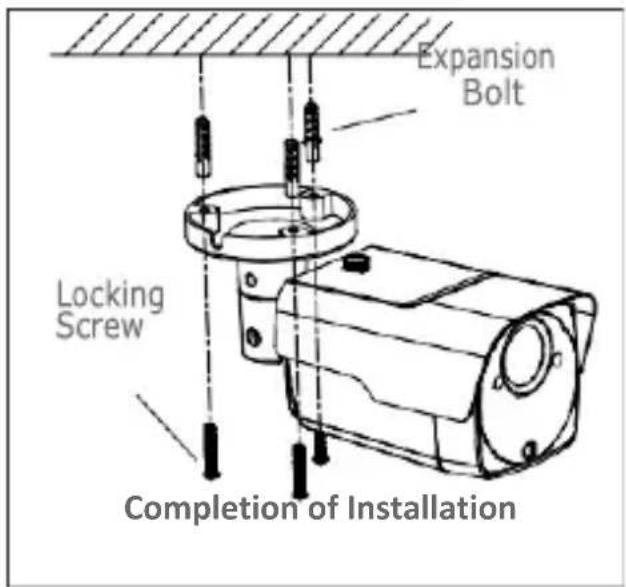
text_image
Expansion Bolt Locking Screw Completion of Installation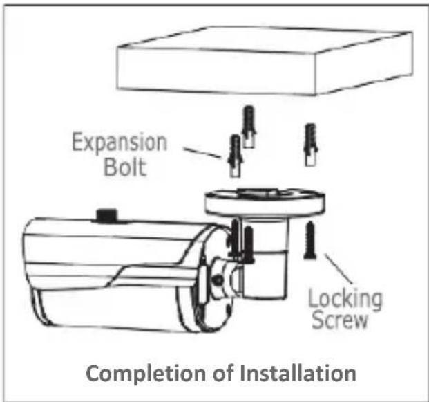
text_image
Expansion Bolt Locking Screw Completion of InstallationWall Mounting
Insert three expansion bolts in place into the wall and fix the equipment with three locking screws.
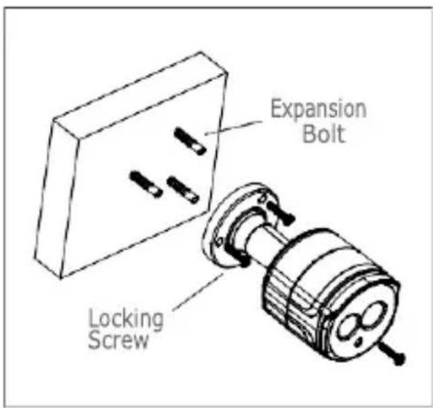
text_image
Expansion Bolt Locking Screw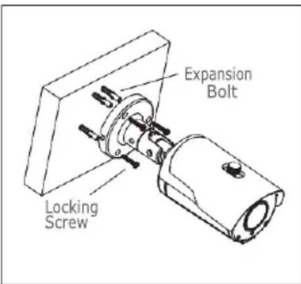
text_image
Expansion Bolt Locking ScrewSD Card Installation
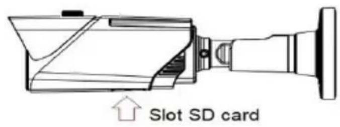
text_image
Slot SD card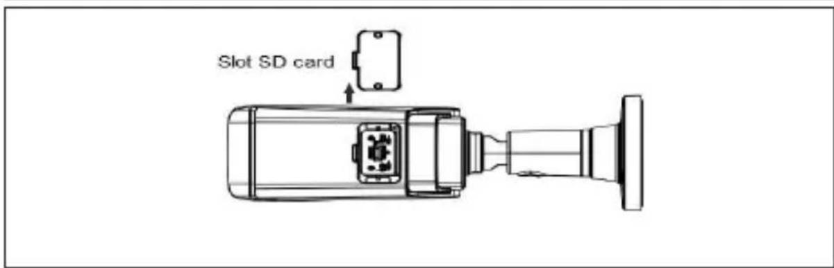
text_image
Slot SD cardSD Card installation model 1099/208A
ATTENTION: this operation must be carried out by qualified personnel.
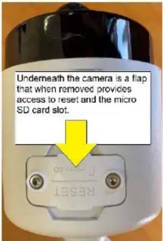
text_image
Underneath the camera is a flap that when removed provides access to reset and the micro SD card slot. RESET
text_image
1. Remove the two Allen screws that secure the flap. 2. Insert the micro SD card into the slot provided 3. Close the flap and tighten the screws.INSTALLATION OF MINI DOME CAMERAS
Ceiling Mounting
- Paste the sticker in place at the proper position as selected.
- Remove the collar off the camera by rotating it down.
- Fix the pedestal by drilling locking holes around the sticker and inserting three expansion bolts into the holes and fastening it with three locking screws.
- Adjust it to an appropriate angle.
- Mount the collar back by rotating it up.
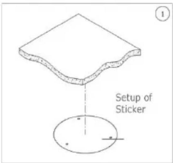
text_image
Setup of Sticker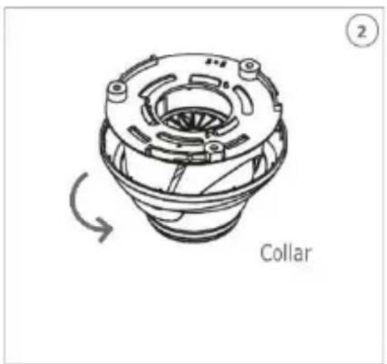
text_image
Collar ②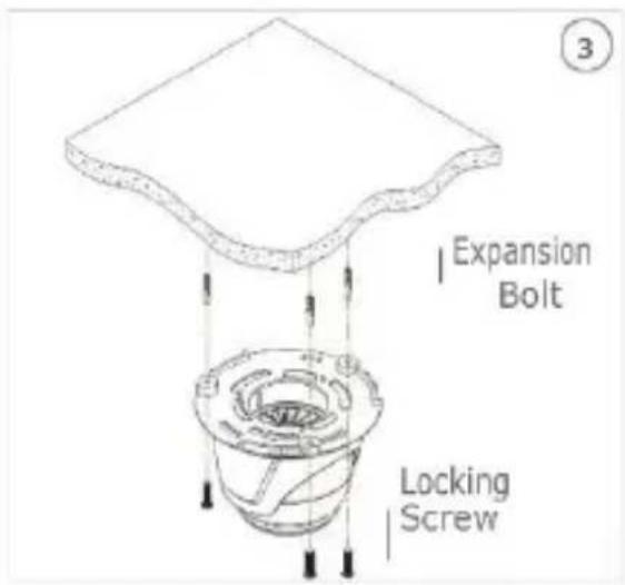
text_image
Expansion Bolt Locking Screw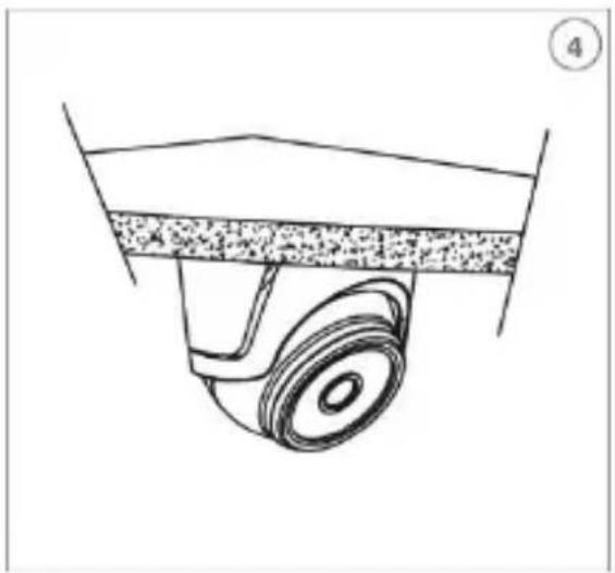
natural_image
Technical line drawing of a mechanical component with a wheel and textured base (no text or symbols)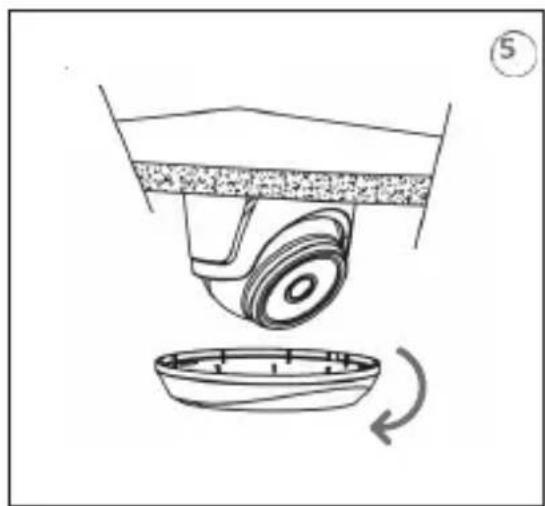
natural_image
Diagram of a mechanical device with a wheel and base, showing a rotating component (no text or symbols)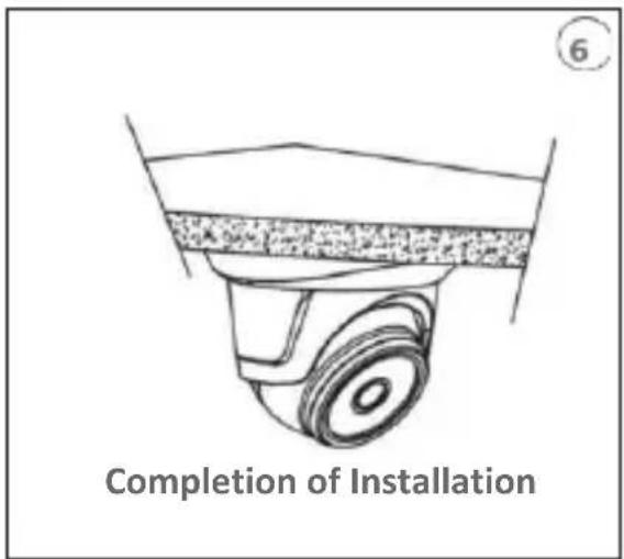
text_image
Completion of InstallationSD Card Installation
text_image
Slot SD cardMINI FLAT CAMERA INSTALLATION
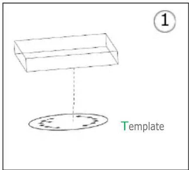
Ceiling fixing
- Fasten the fixing bracket to the ceiling.
- Fasten the camera body to the ceiling.
- Correctly adjust the angle by rotating the camera body.
- Apply the dome cover of the camera
text_image
① Template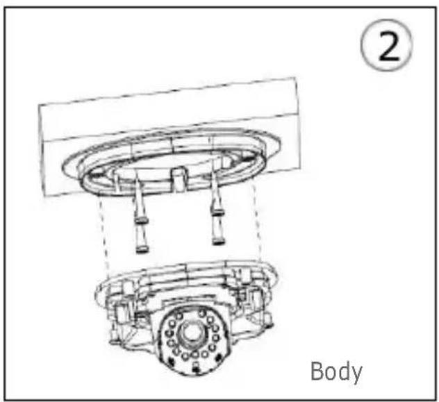
text_image
② Body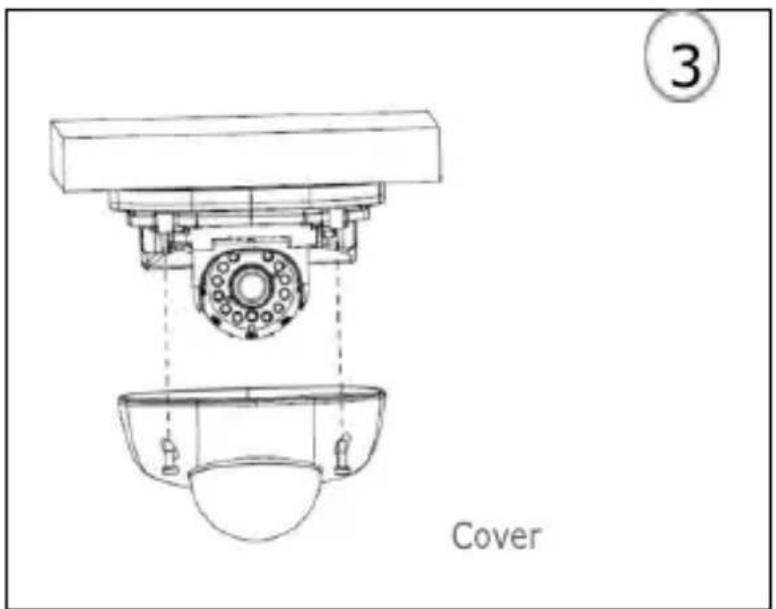
text_image
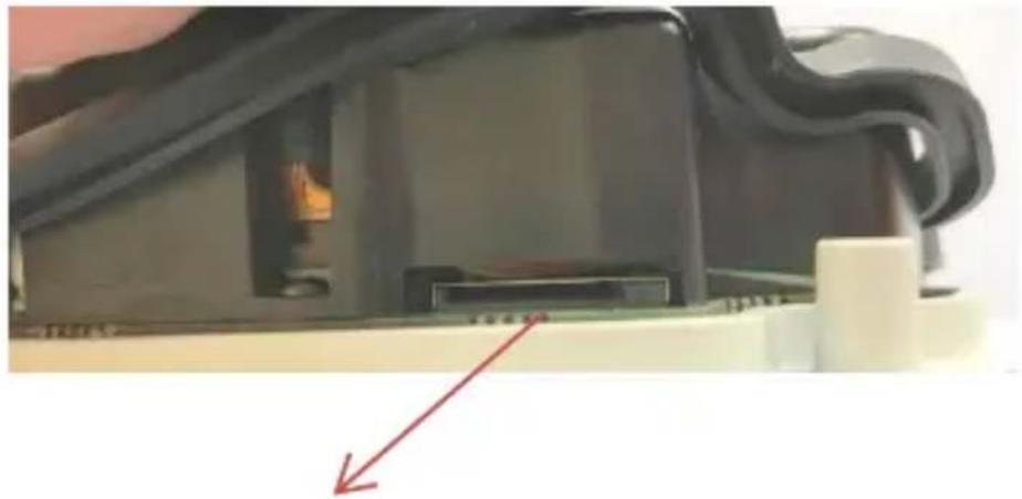
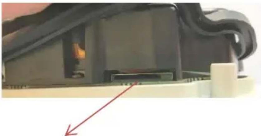
3 CoverSD Card installation
natural_image
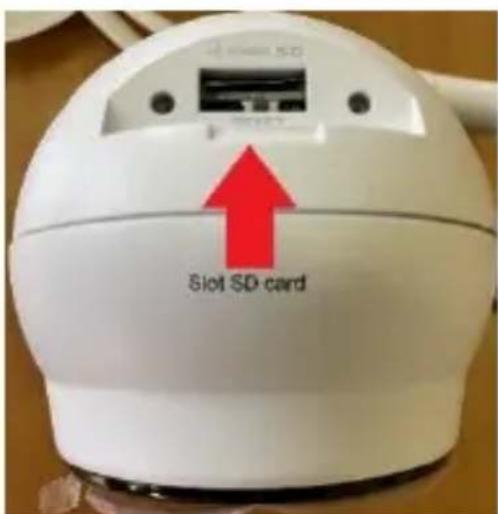
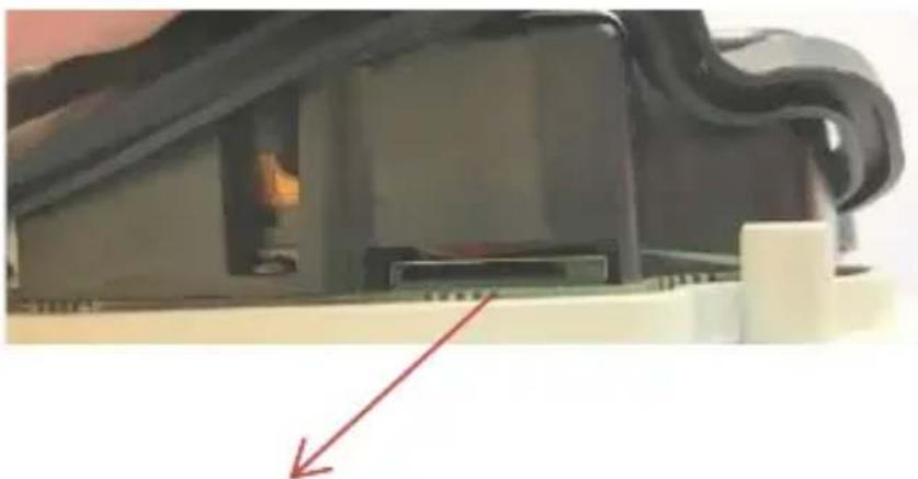
Close-up of a black electronic device with visible internal components and a red arrow pointing to a component (no text or symbols)Insert the SD Card in the slot indicated by the arrow
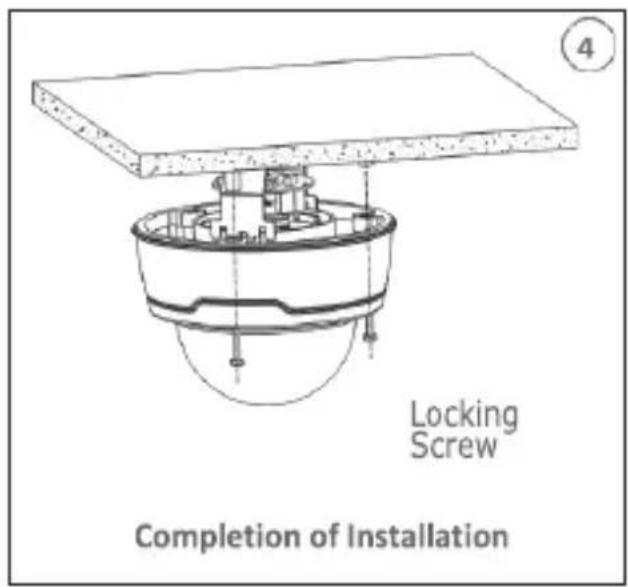
INSTALLATION OF VANDAL-PROOF DOME CAMERAS
Ceiling Mounting
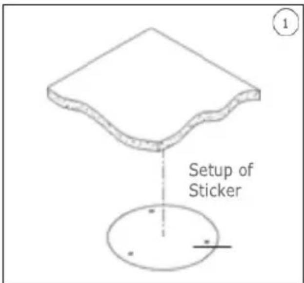
- Paste the sticker in place at the proper position as selected.
- Remove the front component by loosening the three locking screws with a screwdriver.
- Fix the pedestal by drilling locking holes around the sticker and inserting four expansion bolts into the holes and fastening it with four locking screws. Adjust it to an appropriate angle.
- x the front component on the pedestal by tightening the three locking screws.
text_image
Setup of Sticker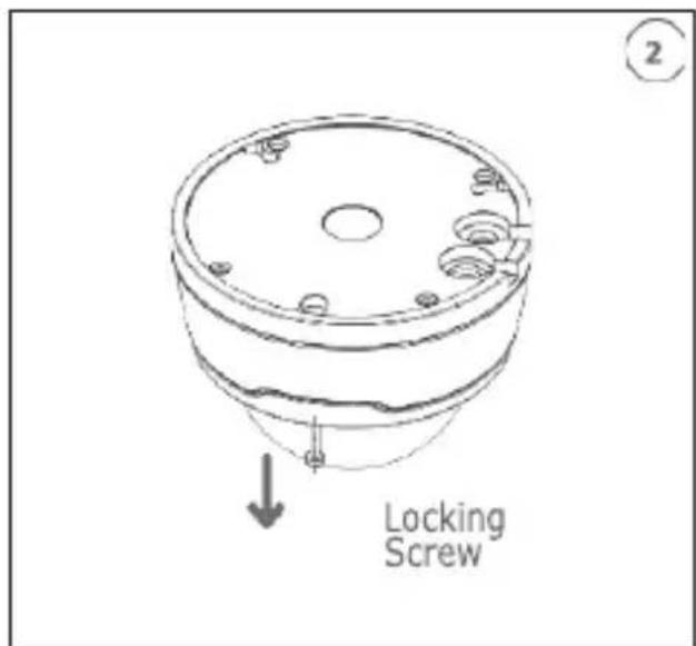
text_image
Locking Screw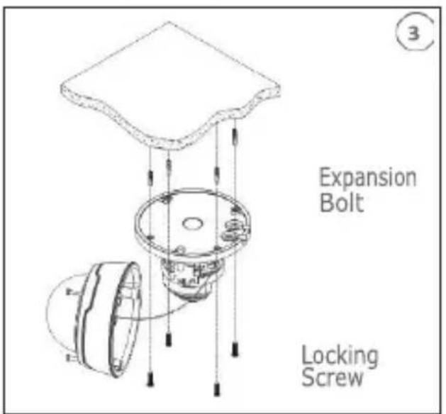
text_image
Expansion Bolt Locking ScrewSD Card Installation
text_image
Locking Screw Completion of Installation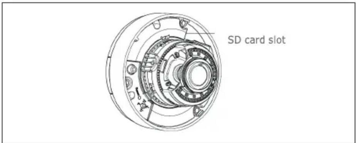
text_image
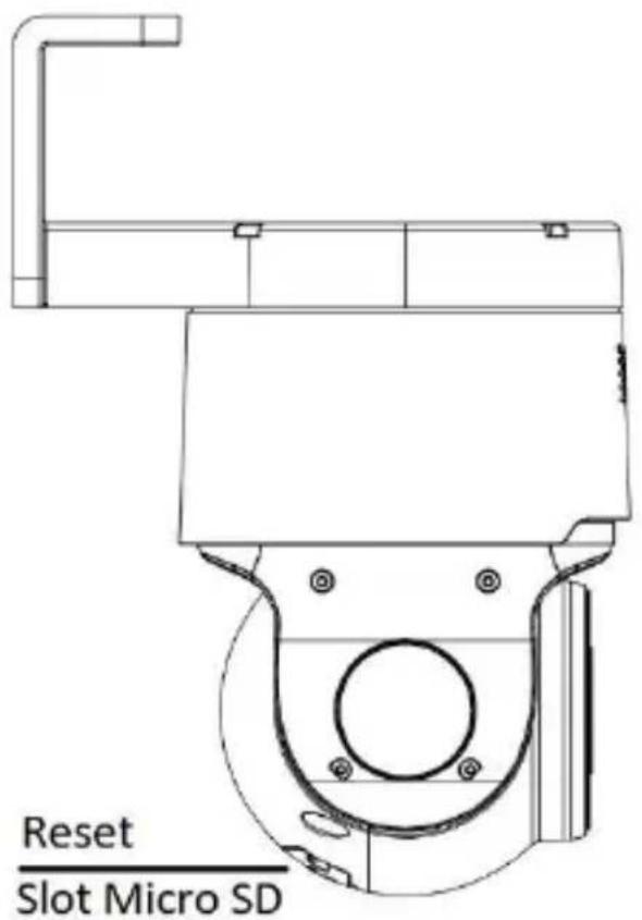
SD card slotPTZ CAMERA 4K 4X DETERRENCE
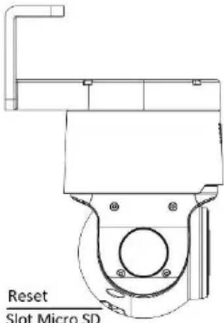
text_image
Reset Slot Micro SD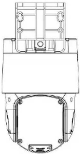
natural_image
Technical line drawing of a mechanical component with mounting holes and internal brackets (no text or symbols)INSTALLATION OF SPEED DOME IP CAMERA 25X-33X
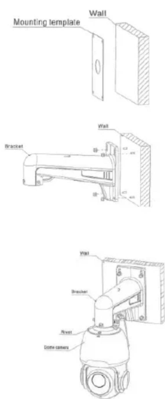
- Stick the mounting template to the wall, drill 4 expansion screw holes. Hammer the 4 expansion screws into the drilled wall holes.
- Align the 4 expansion screws with the holes of the bracket, install the gasket and spring washer, then lock the 4 nuts.
- Fasten the anti-dropping rope of the bracket dome camera into the suspending rope loop of the bracket.
- After the tail cable of the dome camera passes through the bracket, align the notch of the adapter cover with the rivet position of the bracket and insert it into the bracket hole.
- After rotating the dome camera to the proper position, tighten the 2 socket head cap screws M6*16 on the bracket.
text_image
Mounting template Wall Bracket Wall Bracket Rivet Dome cameras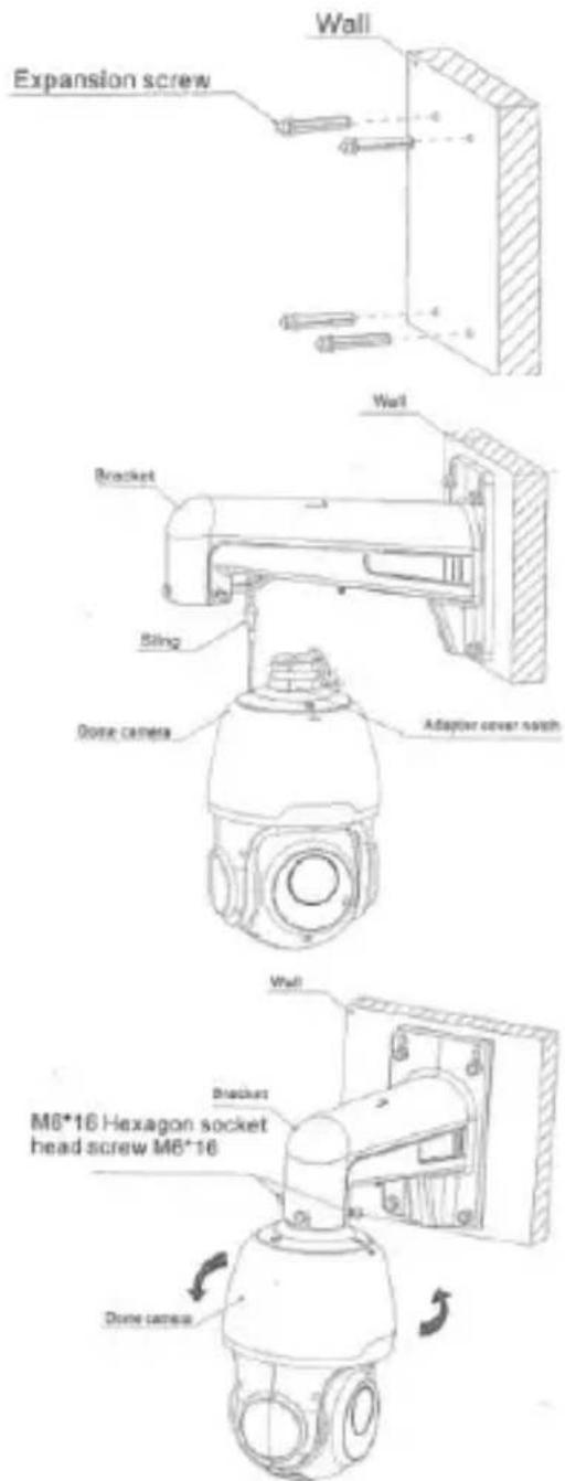
text_image
Expansion screw Wall Bracket Sling Dose camera Adaptor cover mesh M6*16 Hexagon socket head screw M6*16 Bracket Dose cameraIP Camera Configurations
The camera must be configured for the home or office network after it has been powered. It is advisable to install and configure one camera at a time if you are installing multiple cameras on the same network.
CONNECTION TO IP NETWORK WITH DHCP SERVICE
For Quick installation about IP camera with dynamic host configuration (DHCP) on the network will be assigned an IP address automatically. IF DHCP Service is not supported, the default IP Address of IP Camera will be 192.168.1.168.
IP Camera Configuration:
- Install the Software "Device Config. Tool" software, available for download at www.urmet.com. on the product page and by selecting the DOCUMENTATION AND RESOURCES section.
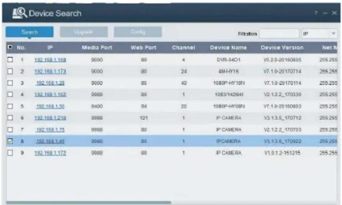
- Launch the "Device Config. Tool" Software, selecting a software tool that it will be displayed automatically IP Address, Subnet Mask, Gateway, and MAC Address for each IP Camera detected in LAN, as shown in picture below.
text_image
Device Search Search Upgrade Config Filtration IP No. IP Media Port Web Port Channel Device Name Device Version Net M 1 192.168.1.169 9000 80 4 DVR-04D1 V5.2.0-20160805 255.255 2 192.168.1.173 9000 80 24 4M-HY16 V7.1.0-20170714 255.255 3 192.168.1.28 9000 80 40 10BOP-HY16N V7.1.0-20170114 255.255 4 192.168.1.162 9988 80 1 1093/142N4I V2.1.2.2_170330 255.255 5 192.168.1.50 9400 94 20 10BOP-HY08N V7.1.0-20160803 255.255 6 192.168.1.210 9988 121 1.IP CAMERA V3.1.3.5_170712 255.255 7 192.168.1.75 9988 80 1.IP CAMERA V2.1.2.2_170703 255.255 8 192.168.1.45 9988 80 1.IP CAMERA V3.1.3.6_170922 255.255 9 192.168.1.172 9988 80 1.IP CAMERA V1.0.1.2-151215 255.255If the searched IP address and PC IP address are not in the same network segment, user may modify IP address, subnet mask, and other parameters of IP camera by
using "Device Config. Tool" software.
First select the device to modify IP address and then input new IP address, subnet mask, gateway and username/password. Insert the password and click Modify" button to change IP address of the device.

text_image
User Info Username admin Password ***** Device Info Start IP Media Port Web Port Gateway Net Mask Net Mode Static Modify*IMPORTANT NOTE: IP camera Default
Settings Default Static IP
Address:192.168.1.168
Username: admin
Password: admin (only for firmware versions prior to V.8.2.2)
Media port: 9000
- Before using IE (Internet Explorer) browser to access the IP camera for the first time, related plug-in components must be installed by following the procedure below:
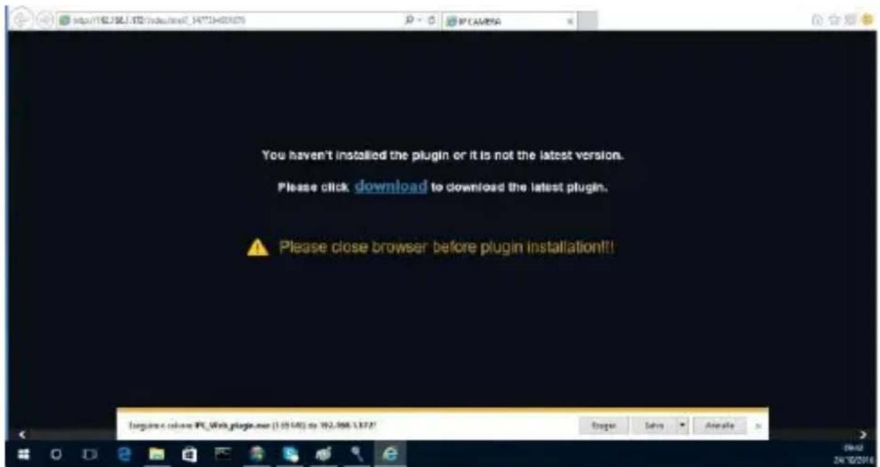
- Access IP address of the IP camera for installing plug-in only for the first time. In the Web Page opened select "Download", after that select "Run" in the pop-up below
text_image
You haven't installed the plugin or it is not the latest version. Please click download to download the latest plugin. Please close browser before plugin installation!!- Wait for plug-in download, after that confirm the ActiveX Installation.
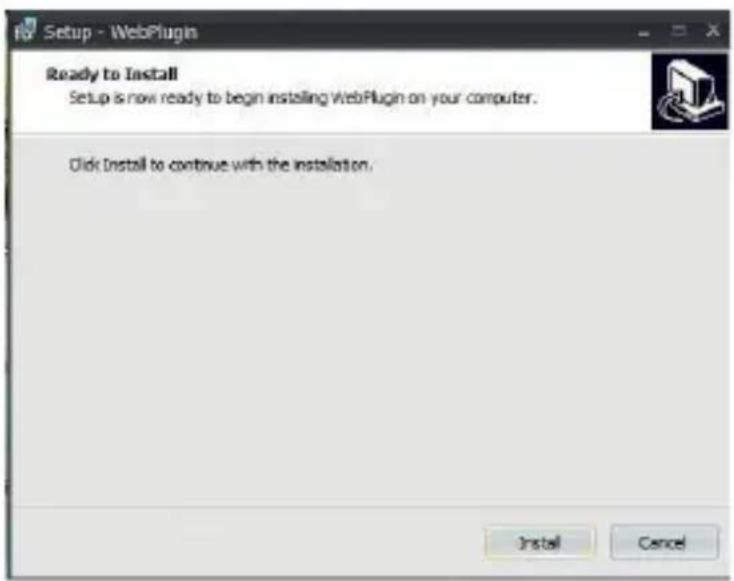
- Select "Install" and wait for the installation is completed.
text_image
Setup - WebPlugin Ready to Install Setup is now ready to begin installing WebPlugin on your computer. Click Install to continue with the installation. Install Cancel- After completed the Active X installation, close the Internet Explorer Web Page and launch it again, put the IP Camera Address.
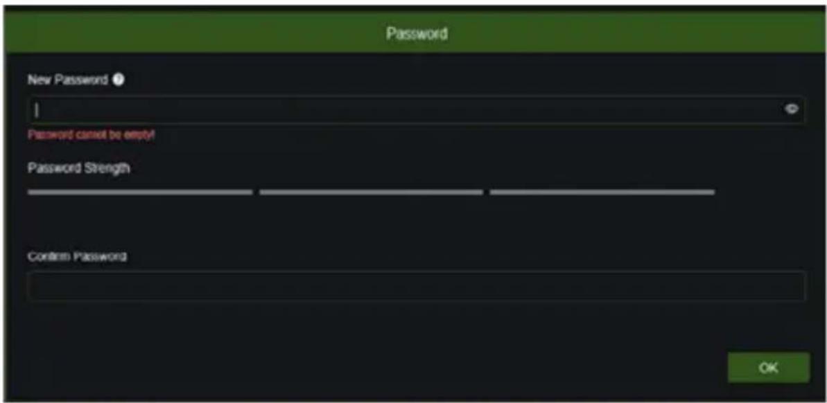
- Open the browser and enter the camera's IP address (http://192.168.1.168) and the window for creating the Administrator password will appear. It is necessary to set the password immediately to protect your privacy. The password should contain a combination of 8 to 15 characters meets the required security criteria. Make a note of the password and keep it in a safe place.
text_image
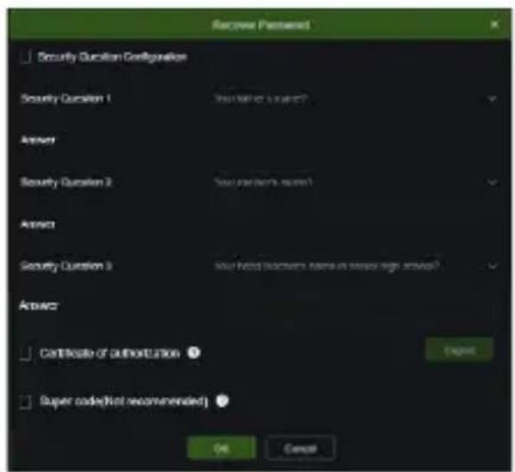
Password New Password ? Password cannot be empty! Password Strength Confirm Password OK- Confirm with OK button. At this point, another window will appear where the user can choose and configure how to recover his password if the user loses it.
text_image
Receive Password Security Question Configuration Security Question 1 Start N/A to Launch? Answer Security Question 2 Your market's name? Answer Security Question 3 Your head teachers name in series high school? Answer Certificate of Authorization OK Super code(Not recommended) OK Cancel- Security Question Configuration: choose one of the proposed questions and fill in the corresponding answer.
Certificate of authorization: it will be possible to export a certificate that can be used to set the password again using the password recovery function.
Supercode: enabling this function, it will be possible to contact Urmet Customer Service to request a Super Code that will allow the user to set a new password using the recovery password function.
Once the options have been selected, confirm with OK.
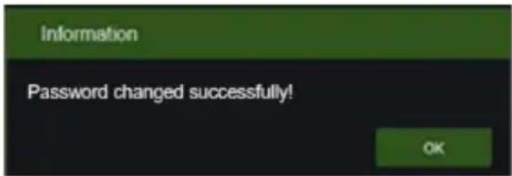
At the end of the password change process, the following window will appear.
text_image
Information Password changed successfully! OKConfirm with the OK button. If no password recovery method is chosen, in the event of a lost password, it will be necessary to act directly on the RESET button (located on the camera), thus returning the camera to its factory parameters.
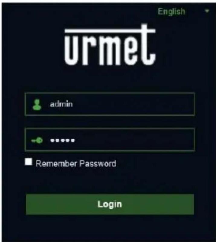
The LOGIN screen shown below will now appear:
text_image
English urmet admin ...... Remember Password Login-
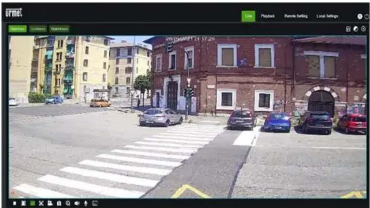
Select "Login" in order to enter in LIVE screen.
-
Click the buttons on the top left corner in the Web Page to select the stream to display (Main Stream, Sub Stream or Mobile Stream)
text_image
urmet Playback Remote Setting Local Settings 2010/03/20 21:17:20PTZ CONTROL

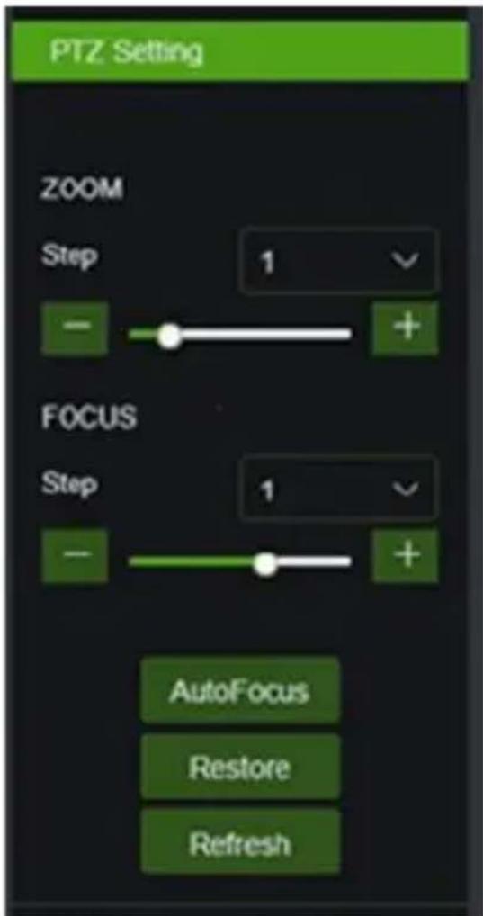
(PTZ control) select the icon to open the following window:
On Autofocus cameras, the PTZ interface will be as follows:
text_image
PTZ Setting ZOOM Step 1 - + FOCUS Step 1 - + AutoFocus Restore Refresh| Option | Value | Explanation |
| Zoom | Step/-/+ | Manually adjusts zoom (+ zoom in / - zoom out)Step: defines zooming speed |
| Focus | Step/-/+ | Manually adjusts focus (+ increase / - decrease)Step: defines focusing speed |
| AutoFocus | / | Adjusts focus automatically |
| Restore | / | Resets PTZ interface default settings (including focus) |
| Refresh | / | Updates the PTZ interface with changes to parameters (including focus) |
PLEASE NOTE
For more details and technical details on programming (e.g. video analysis algorithms), setting (e.g. image controls) and configuration (e.g. user privilege management) please refer to the camera's technical manual.
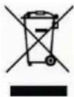
CORRECT DISPOSAL OF THIS PRODUCT
DIRECTIVE 2012/19/EU OF THE EUROPEAN PARLIAMENT AND OF THE COUNCIL of 4 July 2012 on waste electrical and electronic equipment (WEEE) The symbol of the crossed-out wheeled bin on the product or on its packaging indicates that this product must not be disposed of with your other household waste.
Instead, it is your responsibility to dispose of your waste equipment by handing it over to a designated collection point for the recycling of waste electrical and electronic equipment.
The separate collection and recycling of your waste equipment at the time of disposal will help to conserve natural resources and ensure that it is recycled in a manner that protects human health and the environment.
For more information about where you can drop off your waste equipment for recycling, please contact your local city office, your household waste disposal service or the shop where you purchased the product
Guide rapide
H.265 IP CAMERA SERIES
INDICE
INDICE.... 44
Généralités.... 45
AVERTISSEMENTS 45
Installation 48
INSTALLATION CAMERA BULLET 48
INSTALLATION CAMERA MINI DOME 51
INSTALLATION CAMERA MINI DOME 53
INSTALLATION CAMERA ANTI-VANDALE 54
CAMERA PTZ 4K 4X DETERRENCE....55
INSTALLATION CAMERA SPEED DOME IP 25X-33X 56
Configurations IP de l'unite de filmage 57
CONNEXION SUR RESEAU IP AVEC SERVICE DHCP....57
COMMANDE PTZ 62
Généralités
Cher client,
text_image
Slot SD card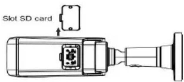
text_image
Slot SD cardtext_image
Collier ②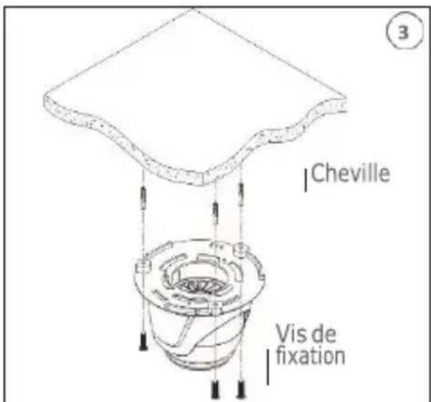
text_image
Cheville Vis de fixation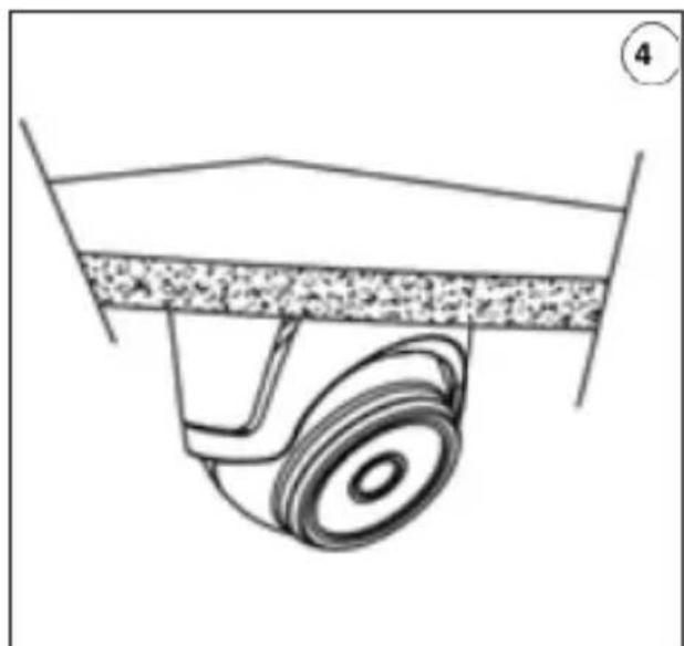
natural_image
Diagram of a mechanical component with a wheel and textured surface (no text or symbols)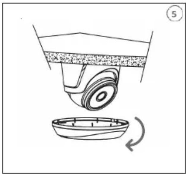
natural_image
Diagram of a mechanical device with a rotating base and a curved component, no text or symbols present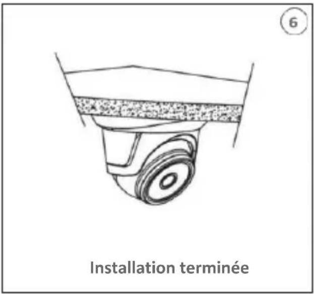
text_image
Installation terminéetext_image
Slot SD cardINSTALLATION CAMERA MINI DOME
Fixation au plafond
text_image
3 CalotteInstallation Carte SD
natural_image
Close-up of a mechanical component with a red arrow pointing to a detail (no visible text or symbols)natural_image
Technical line drawing of a mechanical component with mounting holes and structural brackets (no text or symbols)INSTALLATION CAMERA SPEED DOME IP 25X-33X
text_image
User Info Username admin Password ***** Device Info Start IP Media Port Web Port Gateway Net Mask Net Mode Static ModifyIdentifiant (UserName): admin
text_image
You haven't installed the plugin or it is not the latest version. Please click download to download the latest plugin. Please close browser before plugin installation!!! Progressives PC_Web plugin.exe (1.65 MB) in TB2.163.172? Google Sales Annals 04/10/2016text_image
Setup - WebPlugin Ready to Install Setup is now ready to begin installing WebPlugin on your computer. Click Install to continue with the installation. Install Canceltext_image
Password New Password ? Password cannot be empty! Password Strength Confirm Password OKtext_image
Recover Password Security Question Configuration Security Question 1 your other name? Answer Security Question 2 your number's name? Answer Security Question 3 your home teacher's name in server high school? Answer Certificate of authorization Export Super code(Not recommended) OK Canceltext_image
Information Password changed successfully! OKtext_image
urmet Use Playback Remote Selling Local Settings Get Inside Customize Unknown 2010/04/20 17:17:29COMMANDE PTZ

text_image
Slot SD card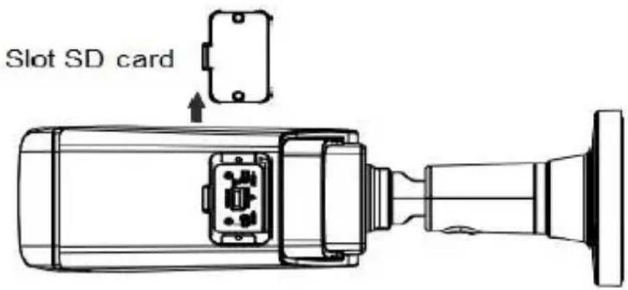
text_image
Slot SD cardnatural_image
Diagram of a mechanical component with a wheel and textured surface (no text or symbols)
natural_image
Diagram of a mechanical device with a rotating base and a curved component, no text or symbols present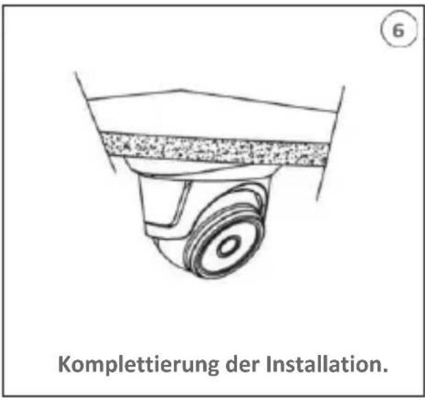
text_image
Slot SD cardINSTALLATION DER MINI-FLAT KAMERA
Deckenmontage
natural_image
Technical line drawing of a mechanical assembly with no visible text or symbols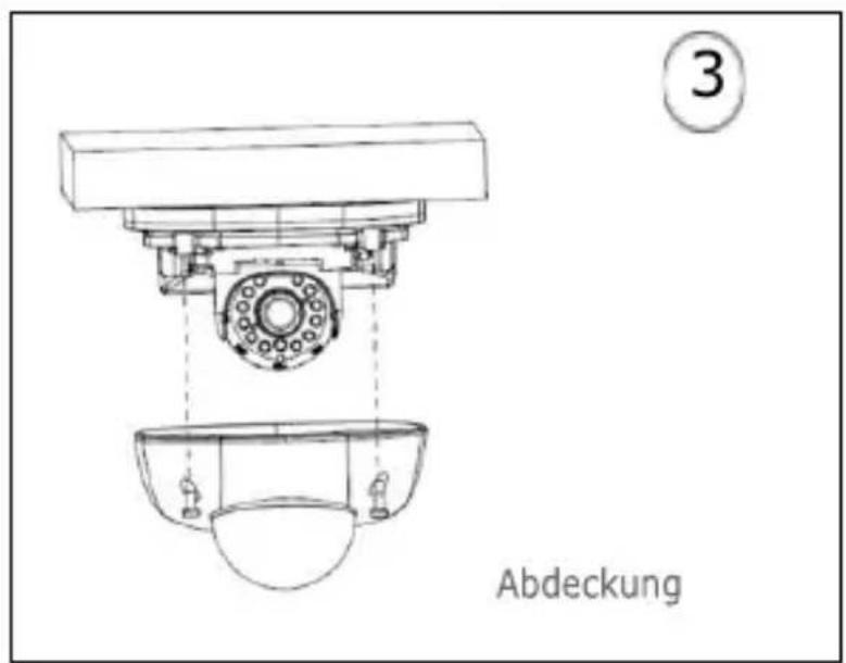
text_image
Abdeckung ③SD-Karten Installation
natural_image
Close-up of a mechanical component with a red arrow pointing to a detail (no visible text or symbols)natural_image
Technical line drawing of a mechanical component with mounting holes and internal structure (no text or symbols)INSTALLATION SPEED DOME IP 25X-33X KAMERA
text_image
User Info Username admin Password **** Device Info Start IP Media Port Web Port Gateway Net Mask .NetMode Static ModifyNutzername (UserName): admin
text_image
You haven't installed the plugin or it is not the latest version. Please click download to download the latest plugin. Please close browser before plugin installation!!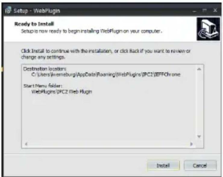
text_image
Setup - WebPlugin Ready to Install Setup is now ready to begin installing WebPlugin on your computer. Click Install to continue with the installation, or click Back if you want to review or change any settings. Destination locations: C:\Users\Iverneburg\AppData\Roaming\WebPlugins\IPC2\IFFChrome Start Menu folder: WebPlugins\IPC2 Web Plugin Install Canceltext_image
Password New Password ? Password cannot be empty! Password Strength Confirm Password OKtext_image
Recover Personal Security Question Configuration Security Question 1 Your other's name? Answer Security Question 2 Your mother's name? Answer Security Question 3 Your home teacher's name in some high school? Answer Certificate of authorization Super code(Not recommended) OK Canceltext_image
Information Password changed successfully! OKtext_image
urmet Playback Remote Setting Local Settings 20/04/2021 11:17:29PTZ-STEUERUNG

text_image
QR code image containing encoded data, no visible human-readable texttext_image
QR code image containing encoded data, no visible human-readable textFor assistance and information about Urmet products and systems you can scan this QR code with your smartphone or visit
www.urmet.com >> Contacts >> Export Sales Network
Urmet S.pA. reserves the right to make changes to its products at any time, without prior notice.
www.urmet.com | info@urmet.com
All Urmet products bear the mark C €
Made in China to Urmet specifications.

Customer Care
Italia: 011 23 39 810
Export Dept.: +39 011 24 00 250/256
MADE IN CHINA
To Urmet Specification

urmet
URMET S.p.A.
Via Bologna, 188/C | 10154 Torino (ITALY)
www.urmet.com | info@urmet.com