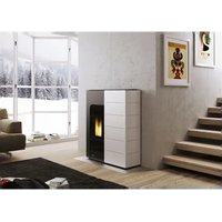
Ecofire Ginger 9 air - Frying Pan Palazzetti - Free user manual and instructions
Find the device manual for free Ecofire Ginger 9 air Palazzetti in PDF.


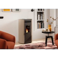
| Product type | Wood pellet stove (pellet) |
| Brand | Palazzetti |
| Model | Ecofire Ginger 9 air |
| Fuel | Wood pellets (pellets) complying with UNI EN 14961-2 category A1 or A2 |
| Estimated thermal power | 9 kW |
| Power supply | 230 V ~ 50 Hz |
| Approximate dimensions (H x W x D) | 100 cm x 50 cm x 50 cm |
| Approximate weight | 110 kg |
| Pellet hopper | Yes, capacity indicated in the technical manual |
| Installation type | On floor with sufficient load-bearing capacity, connection to a certified flue |
| Safety distances | Respect minimum distances from flammable materials (see technical manual) |
| Reference standards | Directive 2006/95/EC, 2004/108/EC, EU Regulation 305/2011 |
| Legal warranty | Compliant with directive 1999/44/EC, subject to compliance with instructions |
| Routine maintenance | Regular cleaning of the burner, glass, ash pan |
| Annual maintenance | Mandatory by an authorized technician (complete cleaning, gasket check, etc.) |
| Safety | Integrated safety devices (sensors, pressure switch); do not open the door during operation |
| Spare parts | Use only Palazzetti original parts |
Frequently Asked Questions - Ecofire Ginger 9 air Palazzetti
User questions about Ecofire Ginger 9 air Palazzetti
0 question about this device. Answer the ones you know or ask your own.
Ask a new question about this device
Download the instructions for your Frying Pan in PDF format for free! Find your manual Ecofire Ginger 9 air - Palazzetti and take your electronic device back in hand. On this page are published all the documents necessary for the use of your device. Ecofire Ginger 9 air by Palazzetti.
USER MANUAL Ecofire Ginger 9 air Palazzetti
natural_image
Close-up of dried plant material with visible grain and root structures (no text or symbols)This manual is an integral part of the product. Read the instructions carefully before installing, servicing or operating the product.
We'd like to thank you for having purchased one of our products and congratulate you on your choice.
To make sure you get the most out of your new stove, please carefully follow the instructions provided in this manual.
DE
natural_image
Pile of dried, segmented wooden sticks or rods against a white background (no text or symbols visible)fig. 3.1
4 MOVIMENTAZIONE E TRASPORTO
natural_image
Diagram of a vertical structure with directional arrows and brick wall, no text or symbols presentfig. 5.3
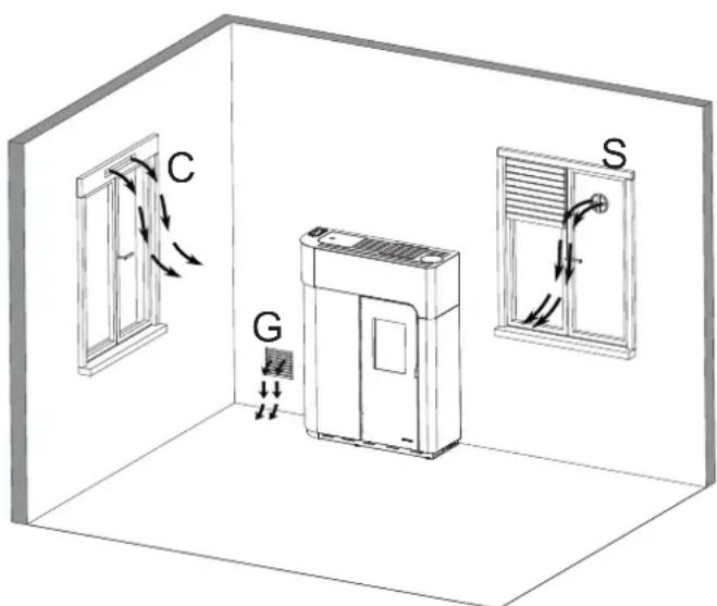
fig. 5.4
natural_image
Technical diagram of a vertical structure with directional arrows, showing internal components and a brick wall (no text or symbols)fig. 5.6
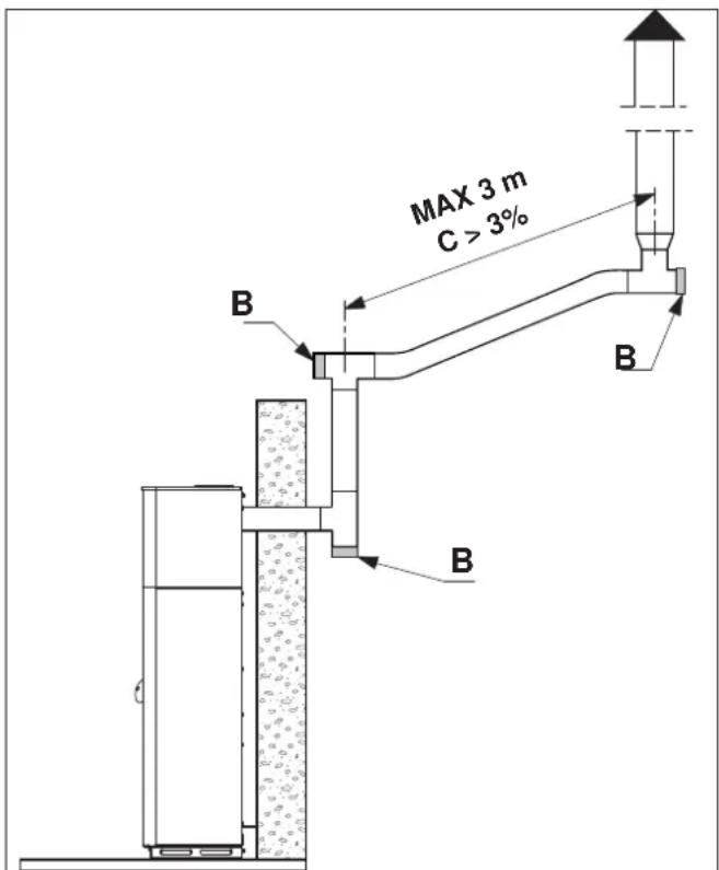
fig. 5.7
natural_image
Simple line drawing of a pipe fitting with a curved tube (no text or symbols)Fig. 5.7a
natural_image
Technical line drawing of a mechanical assembly with a drill bit and housing (no text or symbols)fig. 5.13 r
natural_image
Technical line drawing of a mechanical assembly with a tool and housing (no text or symbols)fig. 5.13 s
5.6 LIVELLAMENTO DELLA STUFA
natural_image
Technical line drawing of a mechanical device with a close-up inset showing a hand holding a small object (no text or symbols present)fig. 5.10
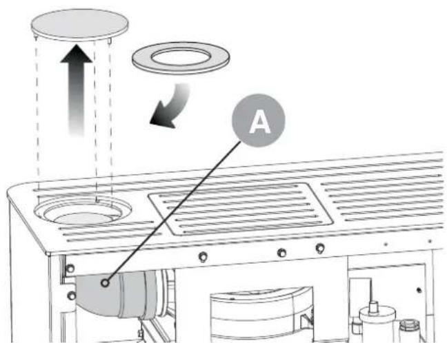
fig. 5.11
natural_image
Exploded view diagram of a computer chassis showing internal components and casing (no text or labels)fig. 5.12
natural_image
Technical line drawing of a mechanical assembly with a magnified inset showing a component detail (no text or symbols)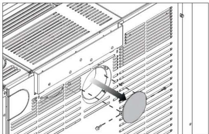
natural_image
Technical diagram of an air duct system with cooling fans and heat exchangers (no text or labels)fig. 5.16
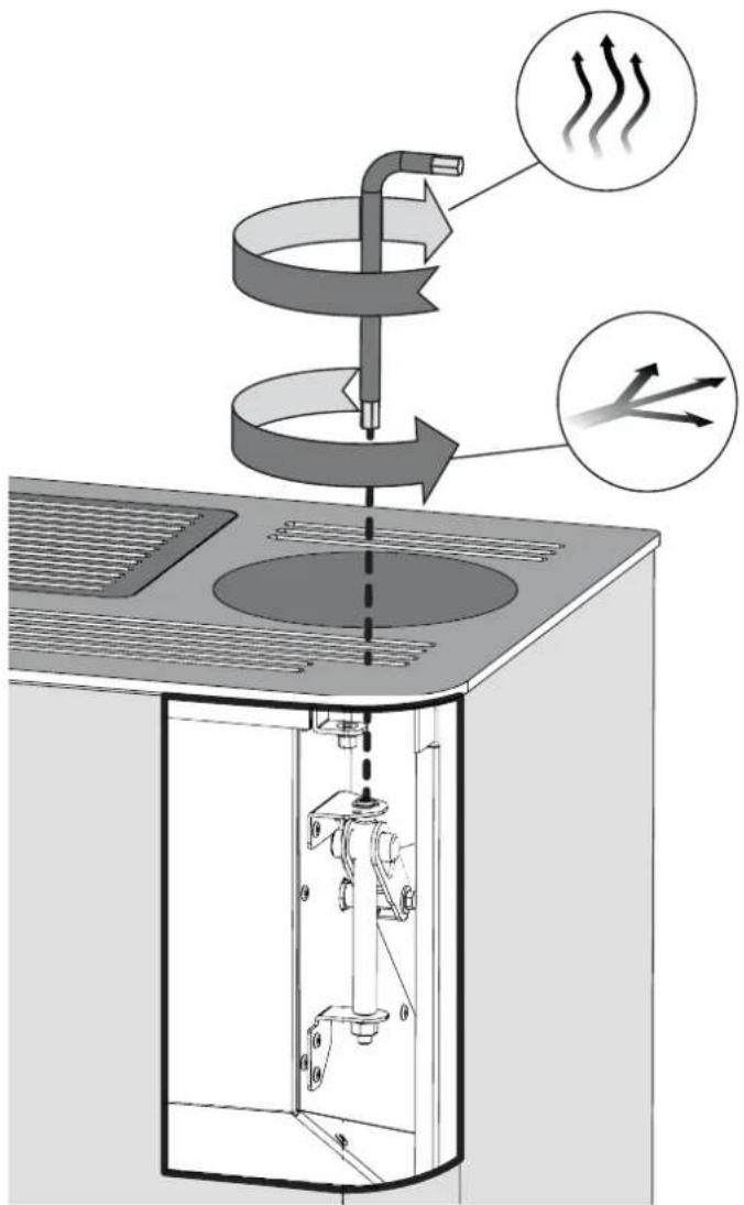
fig. 5.14
natural_image
Line drawing of a refrigerant air conditioner unit with airflow arrows indicating heat or airflow direction (no text or symbols)natural_image
Technical diagram of a solar panel installation with internal components and airflow paths (no text or labels)fig. 6.2
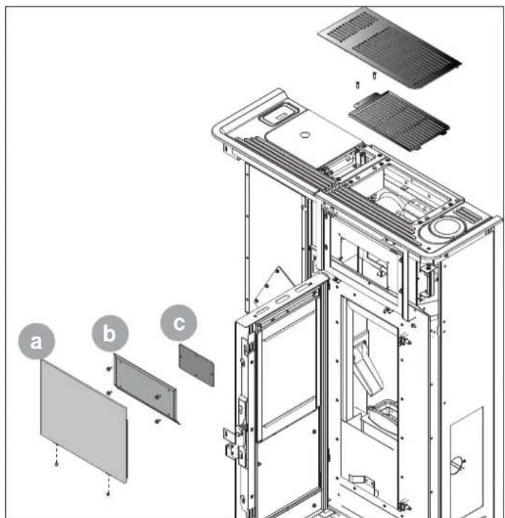
fig. 6.3
natural_image
Simple line drawing of a trash bin with two crossed lines indicating no waste or restriction (no text or symbols)
INDEX
1 INTRODUCTION
1.1 SYMBOLS
1.2 INTENDED USE
1.3 PURPOSE AND CONTENTS OF THIS MANUAL
1.4 HOW TO KEEP THIS MANUAL
1.5 UPDATES TO THE MANUAL
1.6 GENERAL INFORMATION
1.7 MAIN REFERENCE STANDARDS
1.8 PRODUCT WARRANTY
1.9 MANUFACTURER'S LIABILITY
1.10 INTENDED USERS
1.11 TECHNICAL SERVICE
1.12 SPARE PARTS
1.13 IDENTIFICATION LABEL
1.14 DELIVERY OF THE STOVE
2 SAFETY WARNINGS
2.1 INSTALLATION WARNINGS
2.2 MAINTENANCE WARNINGS
2.3 WARNINGS FOR THE USER
3 FUEL SPECIFICATIONS
3.1 FUEL SPECIFICATIONS
3.2 STORING THE PELLETS
4 HANDLING AND TRANSPORT
4.1 REMOVING THE STOVE FROM THE PALLET
5 INSTALLATION
5.1 GENERAL INFORMATION
5.2 SAFETY PRECAUTIONS
5.3 STOVE INSTALLATION SITE
5.4 COMBUSTION AIR
5.9 IMPROVING THE COMBUSTION
6 MAINTENANCE
6.1 MAINTENANCE
7 DECOMMISSIONING AND DISPOSAL
1 INTRODUCTION
The appliance is manufactured and tested to conform with the safety standards indicated in the applicable European directives.
This manual is intended for owners, installers, users and maintenance personnel of stoves and is an integral part of the product. If there are any doubts regarding the contents of this manual, or for any other explanations please contact the manufacturer or an authorised service centre, quoting the paragraph number in question.
No printing, translation and reproduction of this manual, in part or whole, is allowed without the permission of PALAZZETTI. The technical information, illustrations and specifications included in this manual may not be disclosed.
Do not operate the appliance if any of the instructions provided in the manual are not understood; if there are any doubts always contact specialist PALAZZETTI personnel for explanations.
PALAZZETTI reserves the right to modify the technical and/or functional specifications stove at any time, without prior notice.
1.1 SYMBOLS
The most important points in this manual are highlighted by the following symbols:

INSTRUCTION: Instructions concerning correct stove operation and the responsibilities of operators.

IMPORTANT: This denotes very important information.

DANGER: This specifies the behaviour required to prevent accidents or damage to materials.
1.2 INTENDED USE

product is a domestic heating stove, powered exclusively with wood pellets, with automatic operation.
The stove can only operate with the firebox door closed.
Never open the door when the stove is operating.

The appliance is not intended for use by people (including children) with limited physical, sensorial or mental abilities, or without sufficient experience or knowledge, unless they are supervised or instructed on the use of the appliance by a person responsible for their safety.

The intended use of the stove described above and the configurations available are the only ones permitted by the manufacturer: never use the stove in any way not described in the instructions provided.
1.3 PURPOSEANDCONTENTSOFTHISMANUAL
The purpose of this manual is to provide the fundamental and essential rules for correct installation, maintenance and use of the product. Carefully following these rules will ensure a high level of stove safety and productivity.
1.4 HOW TO KEEP THIS MANUAL
STORAGE AND REFERENCE
This manual must be kept with care and must be always available for reference by the user and by assembly and maintenance personnel.
The installation manual is an integral part of the stove.
DAMAGE OR LOSS
If required, an additional copy can be ordered from PALAZZETTI.
SALE OF THE STOVE
If the stove is sold the user must also provide the new owner this manual.
1.5 UPDATES TO THE MANUAL
This manual represents the state-of-the-art at the time the stove was introduced onto the market.
of the
1.6 GENERAL INFORMATION
REQUESTING INFORMATION
If information is requested from the manufacturer of the stove, always refer to the serial number and other identifying data shown on the product's identification label.
SPECIAL MAINTENANCE
Special maintenance operations must be carried out by qualified personnel who are authorised to work on the model of stove that this manual refers to.
RESPONSIBILITY FOR INSTALLATION PALAZZETTI accepts no responsibility for the work carried out to install the stove; such responsibility lies with the installer, who is required to carry out checks on the flue and air intake and ensure installation is completed correctly. Furthermore, all safety standards required by relevant legislation in force in the country where the stove is installed must be complied with.
USE
The stove must only be used in compliance with the instructions provided in this manual, as well as with all safety standards required by relevant legislation in force in the country where the stove is installed.
1.7 MAIN REFERENCE STANDARDS
A) Directive 2006/95/EC: "Electrical equipment designed for use within certain voltage limits".
B) Directive 2004/108/EC: "Approximation of the laws of the Member States relating to electromagnetic compatibility".
C) Directive 89/391/EEC: "Introduction of measures to encourage improvements in the safety and health of workers at work".
D) EU Regulation 305/2011: “sets harmonised requirements for the sale of construction products in abrogation of Directive 89/106/EEC”.
E) Directive 85/374/EEC: "Approximation of the laws, regulations and administrative provisions of the Member States concerning liability for defective products."
F) Directive 1999/5/EC: “Radio equipment and telecommunications terminal equipment and the mutual recognition of their conformity”.
G) UNI/EN 14785/2007: "Residential space heating appliances fired by wood pellets Requirements and test methods".
1.8 PRODUCT WARRANTY
In order to make use of the product warranty pursuant to Directive 1999/44/EC, users must fully comply with the instructions specified in this manual, and specifically:
• always use the stove within its operating limits;
• always carry out regular and thorough maintenance;
- allow the stove to be used by people of proven ability, attitude and suitably trained for the purpose;
- use original spare parts made specifically for the model of stove in question.
• In addition, the following must be provided:
• tax receipt showing the purchase date.
• certificate of conformity of installation issued by the installer.
Failure to follow the instructions provided in this manual will render the warranty void.
1.9 MANUFACTURER'S LIABILITY

providing this manual, PALAZZETTI declines all liability, both civil and criminal, direct or indirect, deriving from:
- installation not in compliance with the standards in force in the country concerned and with safety directives;
- partial or total failure to follow the instructions provided in this manual;
-
installation by unqualified and untrained personnel;
• use not in compliance with safety directives; -
modifications and repairs on the stove that are not authorised by the manufacturer;
- use of spare parts that are not original or not specific for the model of stove;
- lack of maintenance;
• exceptional events.
1.10 INTENDED USERS
! The user of the stove must be a responsible adult with sufficient technical knowledge to carry out routine maintenance on the parts of the stove.

Make sure children do not play close to the stove while it's operating.
1.11 TECHNICAL SERVICE
PALAZZETTI has an extensive network of service centres staffed by specialists trained directly by the company.
Please contact our head office or sales network for details of your nearest authorised service centre.
1.12 SPARE PARTS
Only use original spare parts.
Do not wait for components to become worn out before replacing them.
Replace a worn component before it malfunctions helps prevent accidents due to sudden breakages, which may cause serious harm to people and things.
Perform the periodical maintenance checks as described in the chapter on "Maintenance".
1.13 IDENTIFICATION LABEL
The serial number plate on the stove shows all the typical product data, including the manufacturer's details, the serial number and markings.
1.14 DELIVERY OF THE STOVE
The stove is delivered packaged in a cardboard box or shrink-wrap and secured to a wooden pallet for handling by forklift and/or other equipment.
The following material is provided inside the stove:
• instruction manuals;
• tool for opening of the firebox door (only on models where featured);
• air adjustment tool;
2 SAFETY WARNINGS
2.1 INSTALLATION WARNINGS
Comply with the requirements specified in this manual.
The stove assembly and dismantling instructions are reserved exclusively for specialist technicians.
Users should always contact our service centre to request work to be performed by qualified technicians. Before having work performed by other technical personnel verify their effective technical competence.
Responsibility for work carried out in the place where the stove is installed lies with the user; the user is also responsible for making sure the installation checks are completed.
The user must abide by all local, national and European safety requirements.
The appliance must be installed on floors with a suitable load-bearing capacity.

Make sure that the flue and air intake duct arrangements correspond to the type of installation.
Do not make any electrical connections using temporary or uninsulated cables.
Make sure the electrical system is earthed correctly.
Before starting to assemble or dismantle the stove, the installer must heed the safety precautions required by law, specifically:
A) do not work in adverse conditions;
B) always be in a fit mental-physical state for working and make sure that personal protective equipment is in perfect working order;
C) always wear safety gloves;
D) always wear safety shoes;
E) always use electrically insulated tools;
F) make sure that the area being used for assembly and dismantling is clear of any obstacles.
2.2 MAINTENANCE WARNINGS

ply with the requirements specified in this manual.
- Use always personal protective equipment and other means of protection.
- Before starting any maintenance work make sure that the stove, if it had been operating, has cooled down.
- If even just one of the safety devices is not calibrated or not working, the stove must be considered out-of-service.
- Disconnect power before working on electrical or electronic parts and connectors.
2.3 WARNINGS FOR THE USER

pare the stove installation site in accordance with local, national and European regulations.
- As the stove is a heating appliance it has very hot outside surfaces. For this reason maximum care must be paid during operation, specifically:
• do not touch or get too close to the glass door to avoid getting burned;
• do not touch the flue;
• do not perform any type of cleaning;
• do not remove the ash;
• do not open the glass door;
• do not open the ash bin (where featured);
• make sure children keep away from the stove.
• do not place any object on the stove.
Comply with the requirements specified in this manual.
- Follow the instructions and warnings highlighted on the metal labels affixed to the stove.
• These labels are safety devices, therefore they must always be perfectly legible. If damaged or illegible they must be replaced, contacting the manufacturer for an original spare label.
- Only use fuel compliant with the specifications shown in the corresponding chapter of this manual.
- Strictly follow the routine and special maintenance plan.
- Do not use the stove without first having performed the daily inspection as specified in the chapter on "Maintenance" in this manual.
- Do not use the stove in the event of malfunctions, suspected breakage or unusual noises.
- Do not pour or spray water onto the stove when operating or to extinguish the flame in the burn pot.
- Do not switch the stove off by unplugging the power cord.
- Do not rest your weight on the open door as this may affect stability.
- Do not use the stove in any way as a support or anchor.
- Do not clean the stove until the structure and ash have completely cooled down.
- Touch the door only when the stove has cooled down.
- Perform all operations without haste, in such a way as to ensure maximum safety.
- In the event of fire in the chimney switch the stove off.
- In the event of stove malfunctions due to flues with incorrect draught, clean the flue.
- Do not touch the painted parts during operation to avoid damaging the paintwork.
3 FUEL SPECIFICATIONS
3.1 FUEL SPECIFICATIONS
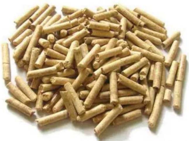
Pellets (Fig. 3.1) are made from various types of mechanically compacted wood in compliance with environmental protection standards. Pellets are the only fuel that can be used on this type of stove.
The efficiency and heat output of the stove may vary in relation to the type and quality of pellets used.
The features of the pellets must comply with the requirements of EN 14961-2 (A1 or A2 category).
The stove has a pellet hopper with the capacity specified in the technical data table in the Product Booklet enclosed.
The pellet hopper is located at the top of the stove. It must always be able to be opened to load the pellets, and must remain closed during operation.

Due to temperature control requirements, operation on traditional wood is not possible.

The stove must not be used as a rubbish incinerator.
3.2 STORING THE PELLETS
The pellets must be kept in a place that's dry and not too cold.
It's suggested to keep some sacks of pellets in the same room where the stove is installed or an adjacent room, as long as the temperature and humidity are acceptable.
Damp and/or cold pellets (5°C) reduce the fuel heat value and mean the burn pot (unburned material) and firebox will need to be cleaned more frequently.

Pay special care when storing and handling the sacks of pellets. Make sure these are not crushed to prevent the pellets from becoming sawdust.
Sawdust introduced into the hopper may block the pellet feed system.
Use of poor quality pellets may affect normal pellet stove operation and render the warranty void.
natural_image
Pile of dried plant material with no visible text or symbolsfig. 3.1
4 HANDLING AND TRANSPORT
The stove is delivered complete with all parts included.
Beware of the tendency of the stove to tip over.
The stove's centre of gravity is towards the front of the appliance.
Always keep this in mind when moving the stove on the transport pallet.
When lifting avoid jolts or sudden movements.
Make sure that the forklift capacity exceeds the weight of the stove being lifted.
The operator of the forklift or other hoisting equipment is responsible for lifting the loads.

Prevent children from playing with the packaging components (e.g. film and polystyrene). Danger of suffocation!
4.1 REMOVING THE STOVE FROM THE PALLET
To remove the stove from the transport pallet follow the instructions shown in the "Product Booklet" enclosed.
5 INSTALLATION
5.1 GENERAL INFORMATION
The following paragraphs provide instructions that must be complied with in order to ensure maximum efficiency of the product purchased.
The following instructions are however subordinate to compliance with any national, regional and local laws and standards in force in the country where the product is installed.
The stove must be installed by qualified personnel in compliance with EN 10683.
5.2 SAFETY PRECAUTIONS
Responsibility for work carried out in the place where the stove is installed lies with the user; the user is also responsible for making sure the installation checks are completed.
The user must abide by all local, national and European safety requirements.
The appliance must be installed on floors with a suitable load-bearing capacity.
The stove assembly and dismantling instructions are reserved exclusively for specialist technicians. Users should always contact our service centre to =request =work =to =be =performed =by =qualified technicians.
Before having work performed by other technical personnel verify their effective technical competence. Before starting to assemble or dismantle the stove, the installer must heed the safety precautions required by law, specifically:
A) do not work in adverse conditions;
B) always be in a fit mental-physical state for working and make sure that personal protective equipment is in perfectly working order;
C) always wear safety gloves;
D) always wear safety shoes;
E) always use electrically insulated tools;
F) make sure that the area being used for assembly and dismantling is clear of any obstacles.
5.3 STOVE INSTALLATION SITE
The enclosed “Product technical details” show the minimum clearances from combustible materials and objects expressed in centimetres that must be observed when positioning the stove; for non-flammable walls/objects, these clearances can be halved.
Protect all structures that may catch fire if exposed to excessive heat.
Floors =made =from =flammable =materials =such =as: wood, parquet, linoleum, laminates or carpets must =be =protected =by =a =suitably-sized =fireproof base underneath stove. Such base may be made from steel, slate, glass or stone and must cover the floor in the part underneath the stove and the flue attachment, and must extend at least 50 cm at the front.
The manufacturer declines all liability for any alterations to the characteristics of the material making up the floor underneath the protective base.
Any elements made from wood (e.g. beams) or other combustible material located near the stove should be protected with fireproof material.
Leave enough clearance for maintenance work, and at least 20 cm on the left side to access the power switch located on the rear of the stove.
Make sure the minimum distance from flammable materials (x) is observed, as shown on the pipes used to make up the flue or chimney (Fig. 5.2).
Pi = Parete infiammabile
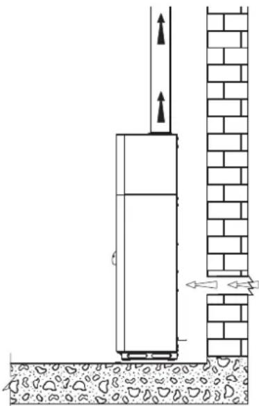
During operation the stove takes in a certain amount of air from the room where it's installed (except for the "Ermetica" series products that can take in air directly from the outside); this air must be replaced through an opening to the outside from the room (Fig. 5.3).
Make the air intake hole on the wall, and let the stove be free to withdraw air in the environment.
If the wall behind of the stove is an outside wall, make an opening for drawing in combustion air around 20-30 cm above the floor, observing dimensions shown on the product data sheet at the end of this booklet.
A permanent non-closable vent cover must be placed on the outside of the opening; in especially windy areas or places exposed to bad weather, install rain and wind protection elements.
Make sure that the air vent is located in such a way that it can't be accidentally obstructed.
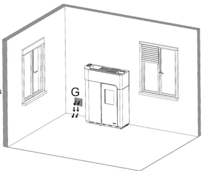
If it's not possible to make a fresh air opening in the wall behind the stove (not a perimeter wall), an opening must be made on the wall in the room where the stove is installed that faces the outside. If no fresh air opening can be made in the room, it can be made in an adjacent room as long as the two rooms are connected by a ventilation grill (Fig. 5.4 - C = Shutter box, G = Grill, S = Shutters)
Standard UNI 10683 prohibits combustion air being drawn in from garages, combustible material stores or places where there is a fire risk.
If there are other heating appliances in the same room, the fresh air vents must guarantee the required volume of air for correct operation of all the appliances.
If one or more exhaust fans (range hoods) are installed and operating in the room where the stove is located, combustion problems may occur due to a lack of combustion air.
the
natural_image
Diagram of a vertical structure with directional arrows and brick wall, no text or symbols presentfig. 5.3

fig. 5.4
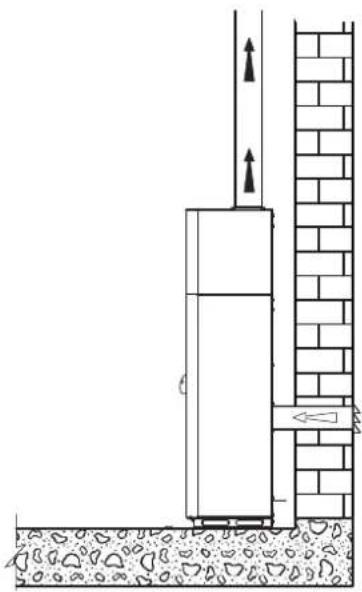
It's possible, alternatively, connect the stove combustion air intake to the fresh air opening using a special pipe (Fig. 5.6).
The stove operates with negative pressure in the combustion chamber, and consequently the flue gas discharge must be airtight.
The stove must be connected to its own separate flue gas exhaust system capable of ensuring adequate atmospheric dispersion of the combustion byproducts.
The components making up the flue gas exhaust system must be suitable for the specific operating conditions and bear the CE mark.
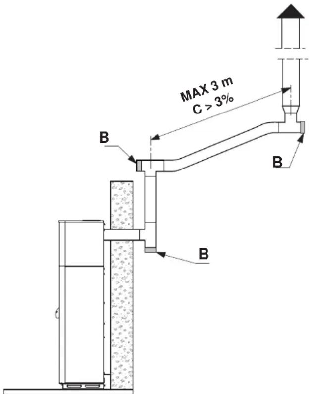
An initial vertical section measuring a minimum of 1.5 metres is required to ensure correct flue gas exhaust.
There should be at least three changes in direction along the flue, in addition to the flue connection at the rear of the stove, using 45 or 90° angle connectors or 'T' connectors (Fig. 5.7).
Use always a 'T' connector with inspection cap on all horizontal or vertical changes in flue direction.
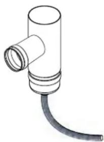
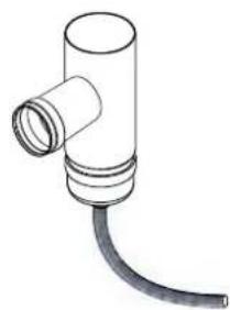
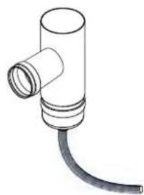
If it is possible connect a pipe at the bottom of the „T“ junction in order to discharge the smoke condensate that could form in the flue gas exhaust (Fig. 5.7a).
The maximum length of horizontal sections is 3 m with an upwards slope of 3% (Fig. 5.7).
Anchor the flues to the wall using special collars.
The flue gas exhaust attachment MUST NOT BE connected to:
- a chimney used by other heat generators (boilers, stoves, fireplaces, etc.....);
- air exhaust systems (range hoods, vents, etc.....) even if these are ducted.
Shut-off or draught valves must not be used.
Combustion byproducts must be discharged through the roof.
natural_image
Diagram of a vertical structure with arrows indicating upward forces, adjacent to a brick wall and ground (no text or symbols)fig. 5.6
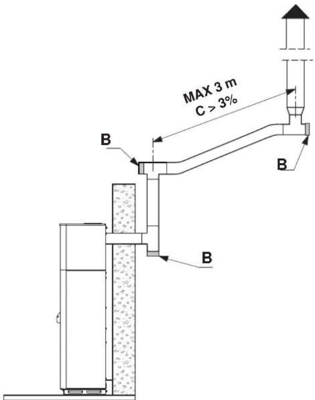
fig. 5.7
natural_image
Simple line drawing of a pipe fitting with a curved cable (no text or symbols)Fig. 5.7a
5.5.1 Dischargethroughroofusingatraditionalchimney
The chimney used to discharge the flue gas must be made in accordance with standards UNI 10683 - EN 1856-1-2 - EN 1857 - EN 1443 - EN 13384-1-3 - EN 12391-1 both as regards the dimensions and the construction materials used.
DAMAGED chimneys made from unsuitable material (asbestos cement, galvanised steel, etc.... with a rough and porous inside surface) are prohibited by law and affect proper stove operation.
The flue gas can be discharged through a traditional chimney (Fig. 5.8) as long as you make sure on the state of maintenance of the chimney.
! For larger chimneys, suitably insulated steel pipes need to be inserted on the inside (diameter according to the length) (Fig. 5.9).
Makes sure connections to brick chimneys are suitably sealed.
! If the flues run through wooden roofs or walls, special certified pass-through kits need to be used, available on the market.
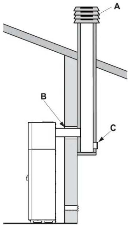
fig. 5.8
A) Chimney pot with wind protection
B) Seal
C) Inspection
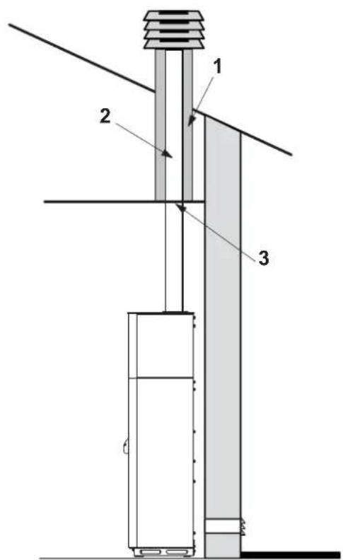
fig. 5.9
1) Vermiculite and/or rock wool.
2) Steel pipes.
3) Closure panel.
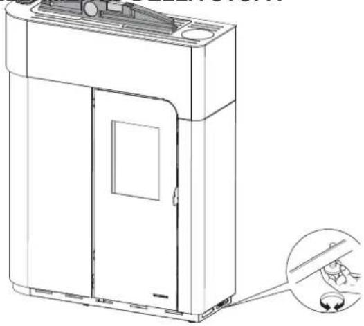
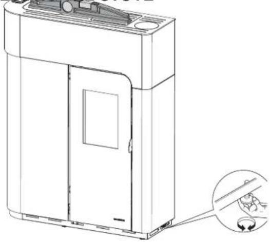
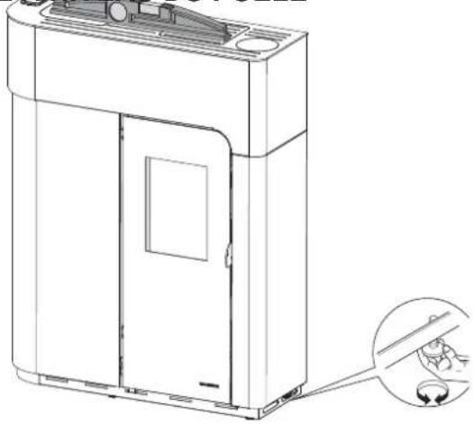
The stove must be levelled by adjusting the feet (where featured), then checked using a spirit level (Fig. 5.10).
5.7 SYSTEM CONNECTIONS
5.7.1 Electrical connection
The stove is connected to the electrical system simply using the plug supplied.
The electrical connection (plug) must be easily accessible when the stove is installed.
! If the power cord is damaged it must be replaced by the technical service or a qualified technician, to prevent any kind of risk.
5.7.1.1 Earth
The system must be earthed and fitted with a residual current circuit-breaker in accordance with legislation in force.
! The flue must have its own earth connection.
5.7.2 Connection to an external timer thermostat
The stove can be connected to an external timer thermostat that switches the stove on or off according to the set temperature.
For electrical connection, refer to the wiring diagram in the technical specifications.
5.7.3 Connection to the smoke outlet (fig 5.11)
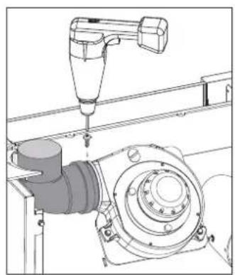
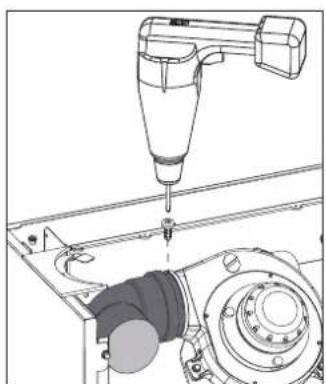
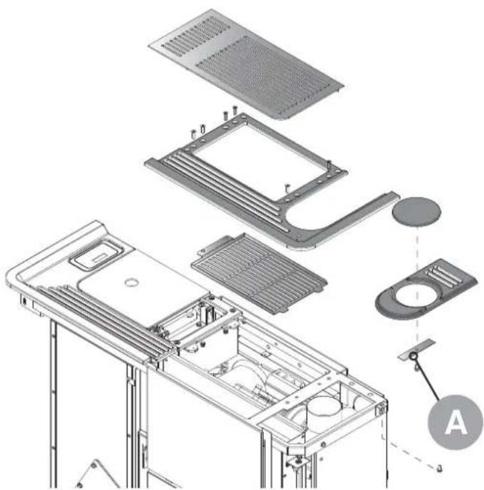
It is possible to connect the stove to the system, rear or top, by simply rotating the output bend (fig. 5.11 -A-). Fix the smoke outlet to the fan with a screw (5.13 r/s).
In the case of upward smoke outlet, remove the top cap by loosening the three screws. Insert the aesthetic ring provided.
Noah model:
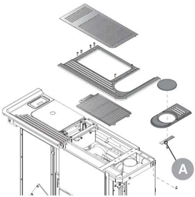
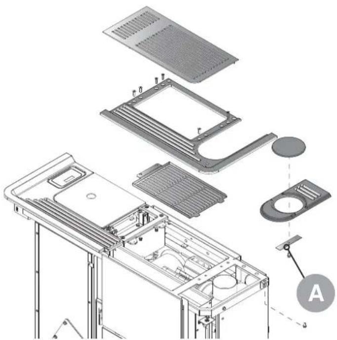
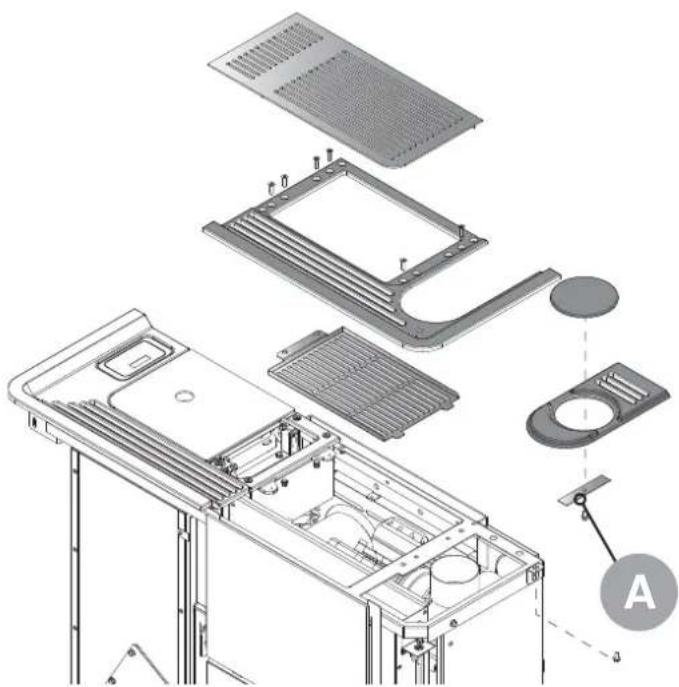
To remove the cap in this model, it is necessary to lift the right top by unscrewing the screws (Fig. 5.12) and taking out the cap after removing the fixing plate (Fig. 5.12 A).
natural_image
Technical line drawing of a mechanical assembly with a drill bit and housing (no text or symbols)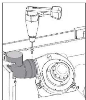
natural_image
Technical line drawing of a mechanical assembly with a tool and housing (no text or symbols)fig. 5.13 r fig. 5.13 s
5.6 LEVELLING THE STOVE
natural_image
Technical line drawing of a mechanical device with a close-up inset showing a hand holding a small object (no text or symbols present)fig. 5.10
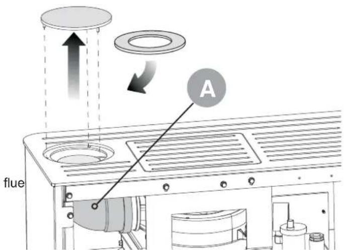
fig. 5.11
natural_image
Exploded view diagram of a computer chassis showing internal components and housing (no text or labels)fig. 5.12
5.8 AIR DUCT
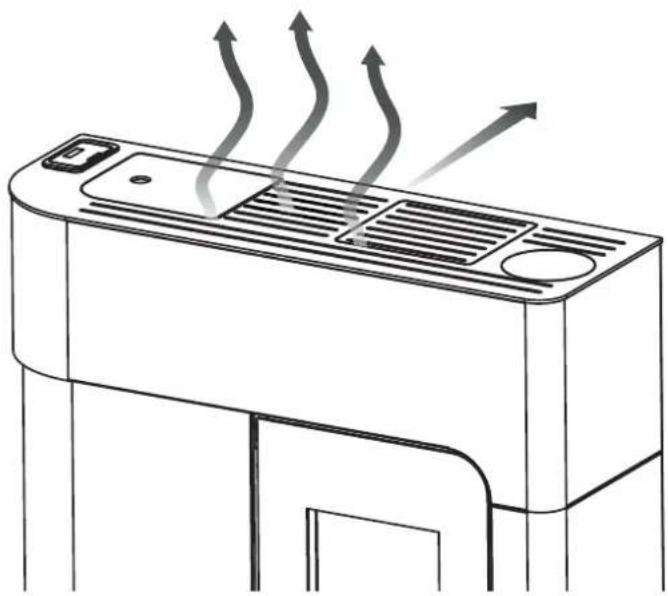
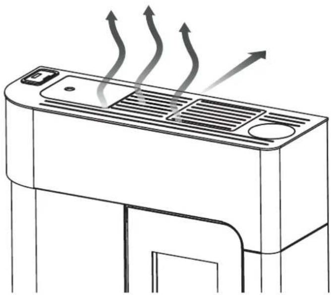
The stove is supplied with a system that allows diverting of the hot air out of a possible rear duct.
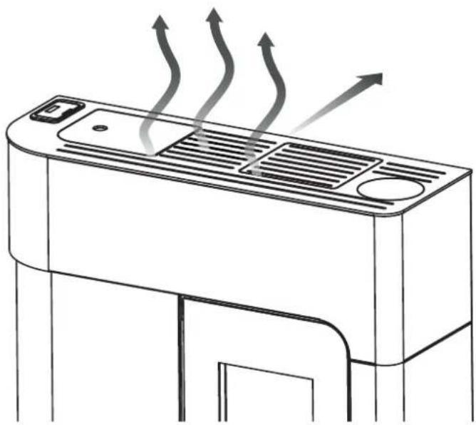
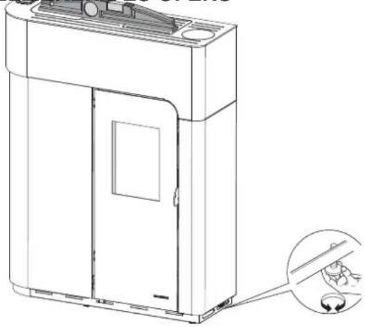
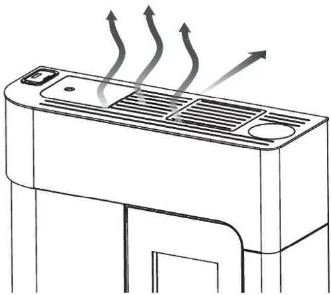
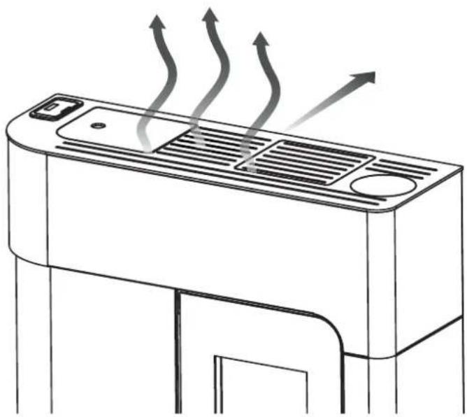
• Using the supplied wrench act on the adjustment screw that is accessible from the top grids of the stove (fig.5.14).
- Turning the screw anti-clockwise, the air will be diverted through the rear duct (a small part is still left to flow from the upper grids)
- Turning the screw clockwise, all the hot air will exit from the upper grids of the stove.
• Intermediate positions of adjustment allow dividing of the air into the two directions.

Warning!
The stove is equipped with a safety device that prevents ducting the air if it has not been previously removed during installation.
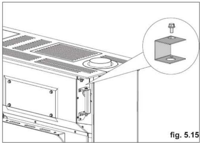
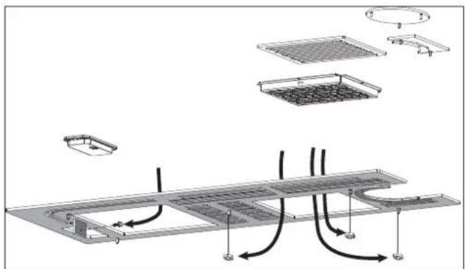
If you intend to connect the stove to a duct system, remove the mounting block, removing the coating and loosening the screw (fig. 5.15).
Remove the back cap to allow air ducting (Fig. 5.16).
natural_image
Technical line drawing of a mechanical assembly with a magnified inset showing a component detail (no text or symbols)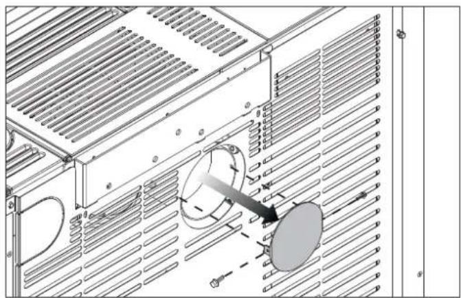
natural_image
Technical line drawing of an air conditioner unit with cooling fins and ventilation grilles (no text or symbols)fig. 5.16
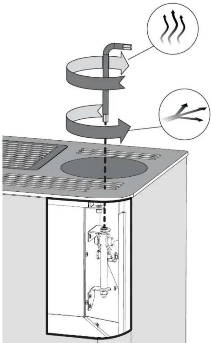
fig. 5.14
natural_image
Line drawing of a refrigerant air conditioner unit with airflow arrows indicating heat or airflow direction (no text or symbols)5.9 IMPROVING THE COMBUSTION
A good combustion depends on several factors (type of installation, operation and maintenance conditions, type of pellet etc ..)
During the first burning, it is possible to optimize the combustion of the stove.
If at the end of combustion in the brazier are many waste, it is advisable to change the combustion configurations (increasing the value) to find most satisfactory solution.
Refer to section "improving the combustion" of the user manual.
6 MAINTENANCE
6.1 MAINTENANCE
The stove may only be maintained by an authorised technical service centre.
Prior to effecting any maintenance operation, adopt the following precautions:
- Make sure that the stove is completely cold.
- Make sure that the ashes have gone out completely.
- Use the personal protective equipment specified in Directive 89/391/EEC..
- Make sure the mains power is off at the master power switch.
- Ensure that the power supply cannot be restored accidentally. Remove the power plug from the socket.
- Always use proper tools.
- Once maintenance or repair activities are completed, reinstall all the protections and reactivate all the safety devices prior to restarting the system.
6.1.1 Servicing the flue system
This must be done at least once a year, or every 4 tons of pellets.
If the flue has any horizontal sections, remove any ash and soot before they can block the flue itself.
If it is not kept clean, the stove may experience problems including:
- poor combustion
- blackened glass
- blocked brazier, accumulated ash and pellets
- ash and excessive encrustations on the heat exchanger, which lower its efficiency.
6.1.2 Servicing the stove
This must be done at least once a year, or whenever the stove itself displays the maintenance required message.
The technician must:
- thoroughly clean the fumes circuit
- check the condition and tightness of all seals
- check the condition and cleanliness of all internal components
- check the tightness and cleanliness of the connection of the flue to the stove
- remove all pellet residue remaining in the pellet tank
- check that the stove is operating properly
- reset any warnings and alarms.
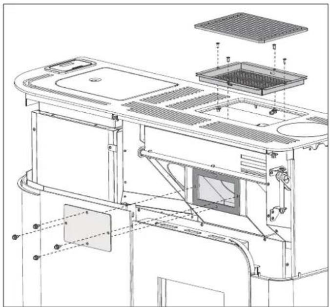
6.1.3 ACCESS TO THE SMOKE FAN
In the event of maintenance, it is possible to access the smoke extraction fan (fig. 6.1):
- raise the upper inspection grid
- loosen the screws that secure the protection grid and remove it from its seat.
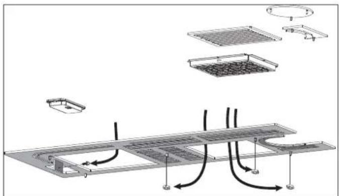
It is possible to clean the smoke plenum beneath the fan by unscrewing the front cap above the door (fig. 6.1). To do this, remove the top (see fig. 6.2) and remove the upper part of the cover.
Noah stove (Fig. 6.3): remove the front cover (6.3a) by removing the two bottom screws, and then the two closing caps (Fig. 6.3 b/c).
natural_image
Technical line drawing of a kitchen appliance interior with labeled components (no text or symbols)fig. 6.1

natural_image
Exploded view diagram of a solar panel installation with cooling fans and heat exchangers (no text or labels)fig. 6.2
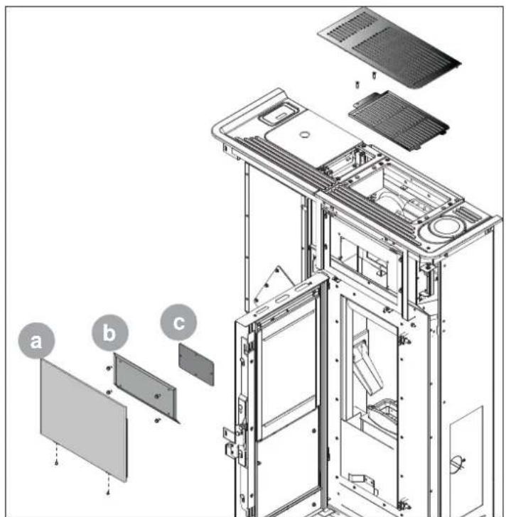
fig. 6.3
INSPECTION AND MAINTENANCE PLAN
| WHENEVER STARTED | WEEKLY | 1 MONTH | 1 YEAR (a) | |
| Burn pot X | ||||
| Ash bin/Compartment X | ||||
| Glass X | ||||
| Heat exchanger X | ||||
| Flue gas manifold X | ||||
| Door and burn pot gaskets* X | ||||
| Flue* X | ||||
| Fans* X |
(*) responsibility of the Authorised Service Centre.
(a) This must be done at least once a year, or every 4 tons of pellets.
7 DECOMMISSIONING AND DISPOSAL
Decommissioning and disposal of the stove are the exclusive responsibility of the owner, who must act in accordance with the laws in force in the country where the stove is installed with regards to safety and environmental protection.
The stove may also be dismantled and disposed of by companies authorised to recover and dispose of the materials in question.

INSTRUCTION: always observe the standards in force in the country where the stove is decommissioned as regards disposal of the materials and the waste disposal report where required.

IMPORTANT: All dismantling operations for decommissioning the stove must be performed when the stove is off and disconnected from the power supply.
- remove all electrical equipment;
• separate the batteries fitted on the electronic boards;
• have the structure of the stove scrapped by an authorised company;

IMPORTANT: Dumping the stove in accessible areas represents a serious hazard to people and animals.
Liability for any harm caused to people or animals always lies with the owner.
When decommissioning the stove the ce mark, this manual and other documents relating to this stove must be destroyed.
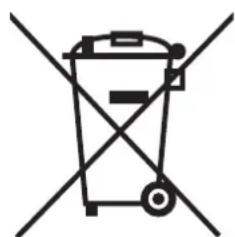
The picture of the bin crossed is labelled on the equipment, and it means that when the device is out of use it has to be kept separated by other wastes.
On the basis of Article 13 by Legislative Decree n°151 of 25th July 2005 actuation of the European Directive 2002/96/CE of 23rd February 2003 on waste electrical and electronic equipment. It is connected to the policy and action which aim to the prevention of waste electrical and electronic equipment, named RAEE, and in
addition, the reuse, recycling and other forms of recovery of such wastes so as to reduce the disposal of waste. It also seeks to improve the environmental performance of all operators involved in the life cycle of electrical and electronic equipment.
natural_image
Simple line drawing of a trash bin with two crossed lines indicating no waste or restriction (no text or symbols)
INHALT
1 ALLGEMEINES VORWORT
natural_image
Pile of dried plant material with no visible text or symbolsfig. 3.1
4 HANDLING UND TRANSPORT
natural_image
Diagram of a vertical structure with directional arrows and brick wall, no text or symbols presentfig. 5.3
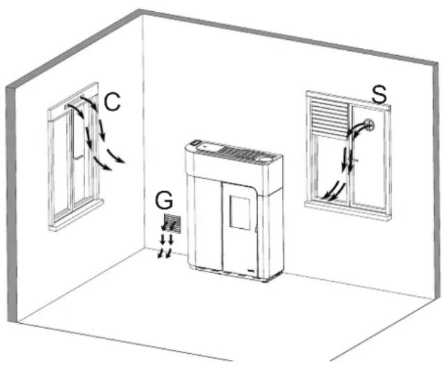
fig. 5.4
natural_image
Diagram of a vertical structure with upward arrows and a brick wall, no text or symbols presentfig. 5.6
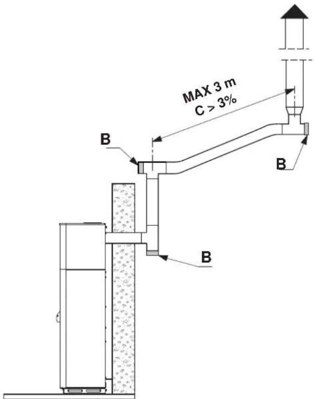
fig. 5.7
natural_image
Simple line drawing of a pipe fitting with a curved tube (no text or symbols)Fig. 5.7a
natural_image
Technical line drawing of a mechanical assembly with a drill bit and housing (no text or symbols)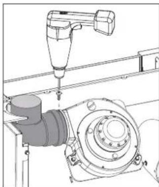
natural_image
Technical line drawing of a mechanical assembly with a tool and housing (no text or symbols)fig. 5.13 r fig. 5.13 s
5.6 NIVELLJEREN DES OFENS
natural_image
Technical line drawing of a mechanical device with a close-up inset showing a hand holding a small object (no text or symbols present)fig. 5.10
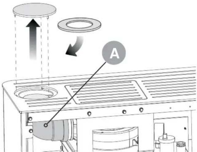
fig. 5.11
natural_image
Exploded view diagram of a computer chassis showing internal components and mounting bracket (no text or labels)fig. 5.12
5.8 LUFTLEITUNG
natural_image
Technical line drawing of a mechanical assembly with a magnified inset showing a component detail (no text or symbols)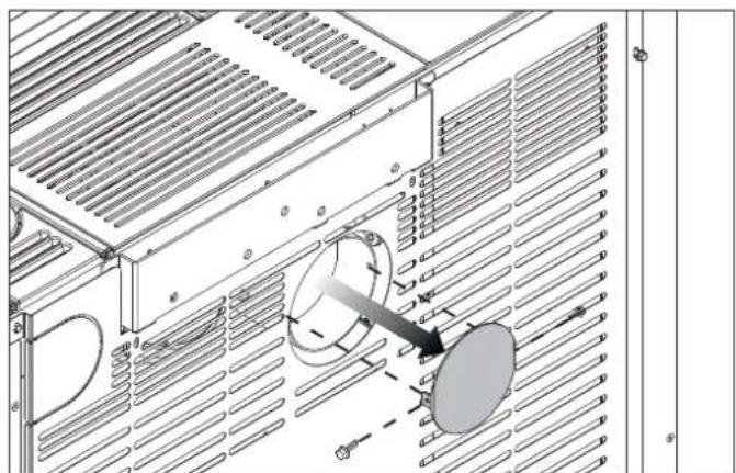
natural_image
Technical diagram of an air duct system with cooling fans and heat exchangers (no text or labels)fig. 5.16
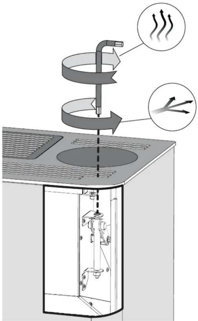
fig. 5.14
natural_image
Line drawing of a refrigerant air conditioner unit with airflow arrows indicating heat or airflow direction (no text or symbols)natural_image
Technical line drawing of a kitchen appliance interior with labeled components (no text or symbols)fig. 6.1
natural_image
Technical diagram of a solar panel installation with internal components and airflow paths (no text or labels)fig. 6.2

fig. 6.3
4 MANUTENTION ET TRANSPORT
4.1 RETRAIT DU POELE DE LA PALETTE DE TRANSPORT
5 INSTALLATION
5.1 CONSIDERATIONS GENERALES
5.2 MESURES POUR LA SECURITE
5.3 LIEU D'INSTALLATION DU POELE
5.4 AIR DE COMBUSTION
5.5 LE DÉCRET N° 2008-1231 ARTICLE R131-2 DISPENSE DE L'ENTRÉE D'AIR DIRECTEMENT EXTÉRIEURE PUISQUE L'APPAREIL DISPOSE DE SA PROPRE AMENÉE D'AIR POUR LES APPAREILS ÉTANCHES.
5.6 ÉVACUATION DE LA FUMÉE
5.7 MISE À NIVEAU DU POELE
5.8 BRANCHEMENTS
5.9 CANALISATION DE L'AIR
5.10 OPTIMISATION DE LA COMBUSTION
6 ENTRETIEN
6.1 ENTRETIEN
7 DESOSSEMENT ET MISE AU REBUT
1 PRÉAMBULE
1.5 MISE A JOUR DU MANUEL
natural_image
Pile of cylindrical plant material, possibly wood chips or similar organic material, with no visible text or symbols.fig. 3.1
4 MANUTENTION ET TRANSPORT
natural_image
Diagram of a vertical structure with directional arrows, adjacent to a brick wall and ground layer (no text or symbols)fig. 5.3
natural_image
Interior view of a room with a large air conditioner unit and a door, no text or symbols presentfig. 5.4
natural_image
Diagram of a vertical structure with upward arrows and a brick wall, no text or symbols presentfig. 5.6

natural_image
Simple line drawing of a pipe fitting with a coiled cable (no text or symbols)Fig. 5.7a
POÊLES DE LA GAMME "ETANCHE"
fig. 5.9
natural_image
Technical line drawing of a mechanical assembly with a drill bit and housing (no text or symbols)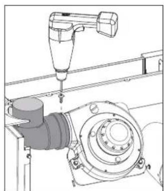
natural_image
Technical line drawing of a mechanical assembly with a tool and housing (no text or symbols)fig. 5.13 r fig. 5.13 s
5.7 MISE À NIVEAU DU POELE
natural_image
Technical line drawing of a mechanical device with a close-up inset showing a hand holding a small object (no text or symbols present)fig. 5.10
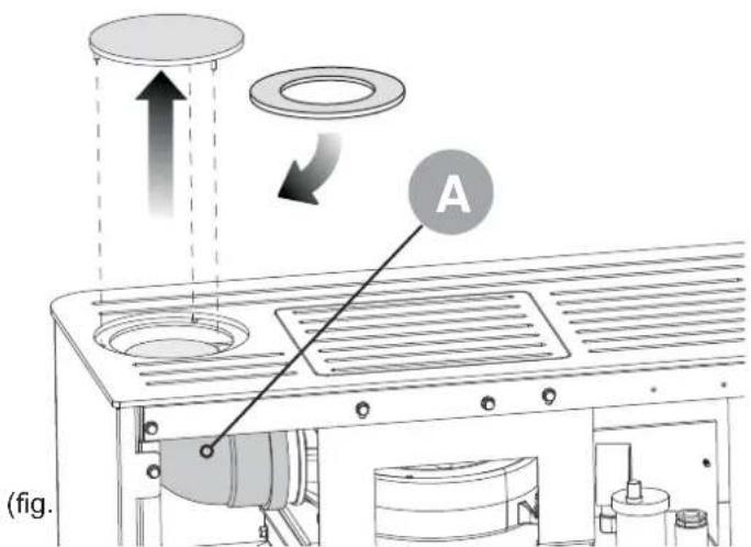
fig. 5.11
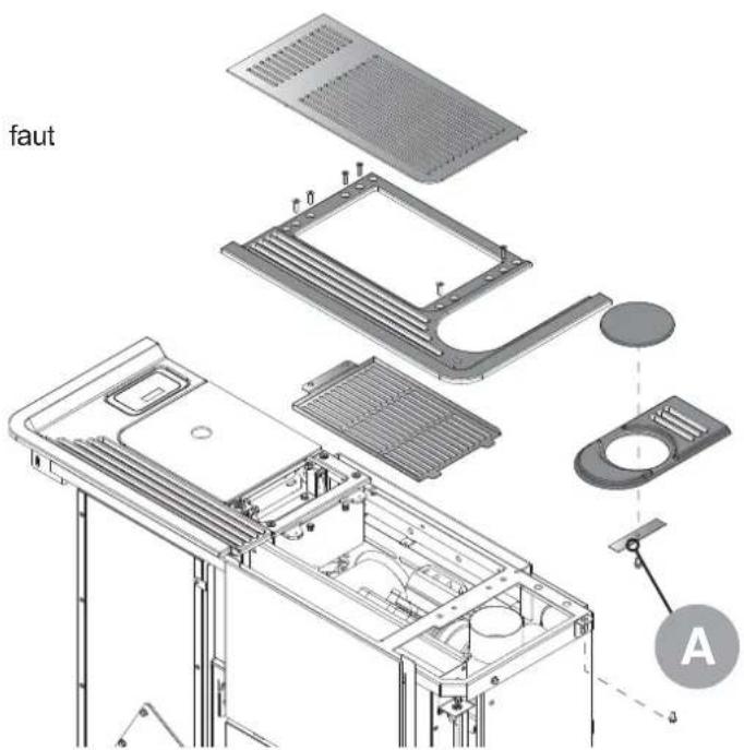
fig. 5.12
5.9 CANALISATION DE L'AIR
natural_image
Technical line drawing of a mechanical assembly with a magnified inset showing a component detail (no text or symbols)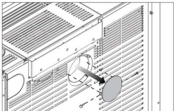
natural_image
Technical diagram of an air duct system with cooling fans and heat exchangers (no text or labels)fig. 5.16
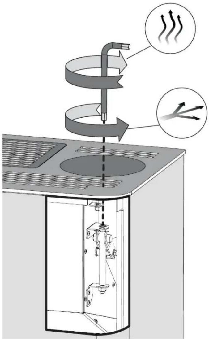
fig. 5.14
natural_image
Line drawing of a refrigerant air conditioner unit with airflow arrows indicating heat or airflow direction (no text or symbols)5.10 OPTIMISATION DE LA COMBUSTION
natural_image
Technical line drawing of a kitchen appliance with labeled components (no text or symbols present)fig. 6.1
natural_image
Exploded view diagram of a solar panel installation with internal components and flow arrows (no text or labels)fig. 6.2
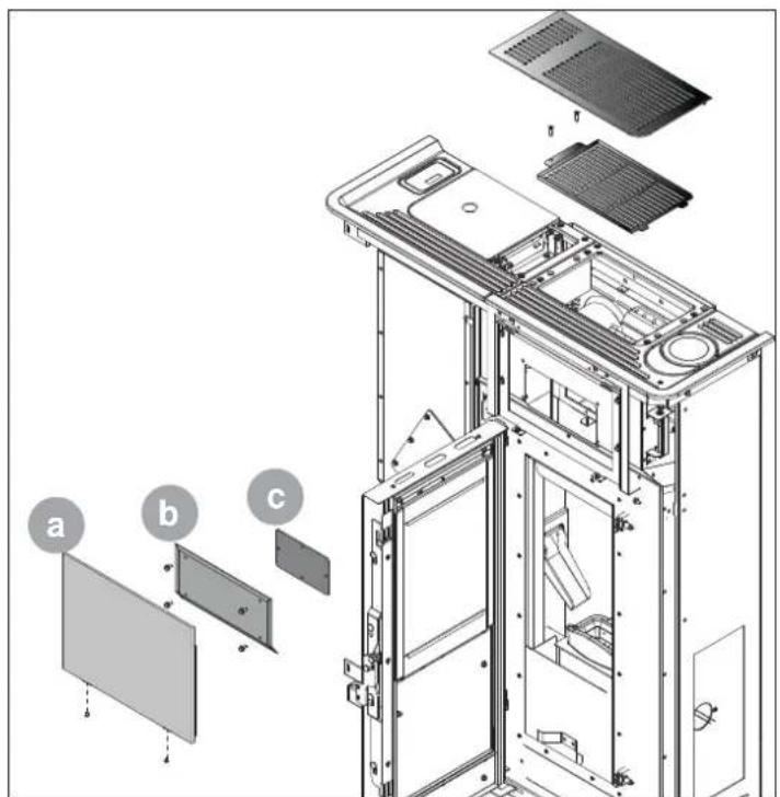
fig. 6.3
PROGRAMME DE CONTRÔLE ET D'ENTRETIEN
natural_image
Simple line drawing of a trash bin with two crossed lines indicating no waste or prohibition (no text or symbols)
ÍNDICE
1 PREMISA GENERAL
natural_image
Pile of dried plant fibers or roots, no text or symbols visiblefig. 3.1
natural_image
Diagram of a vertical structure with directional arrows and brick wall, no text or symbols presentfig. 5.3
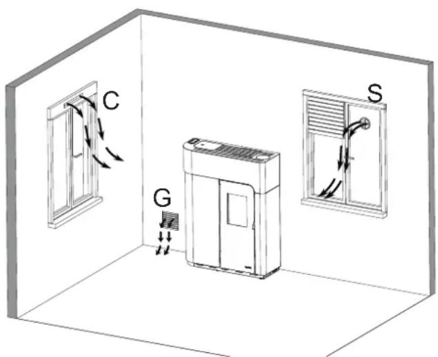
fig. 5.4
natural_image
Technical diagram of a vertical structure with directional arrows, showing internal components and a brick wall (no text or symbols)fig. 5.6
natural_image
Simple line drawing of a pipe fitting with a curved tube (no text or symbols)Fig. 5.7a
natural_image
Technical line drawing of a mechanical assembly with a drill bit and housing (no text or symbols)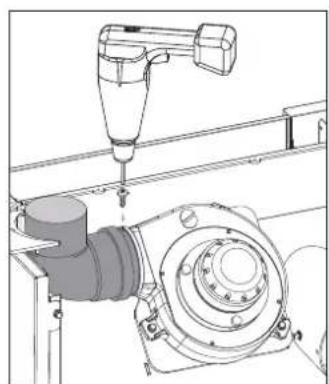
natural_image
Technical line drawing of a mechanical assembly with a tool and housing (no text or symbols)fig. 5.13 r fig. 5.13 s
natural_image
Technical line drawing of a mechanical device with a close-up inset showing a hand holding a small object (no text or symbols present)fig. 5.10
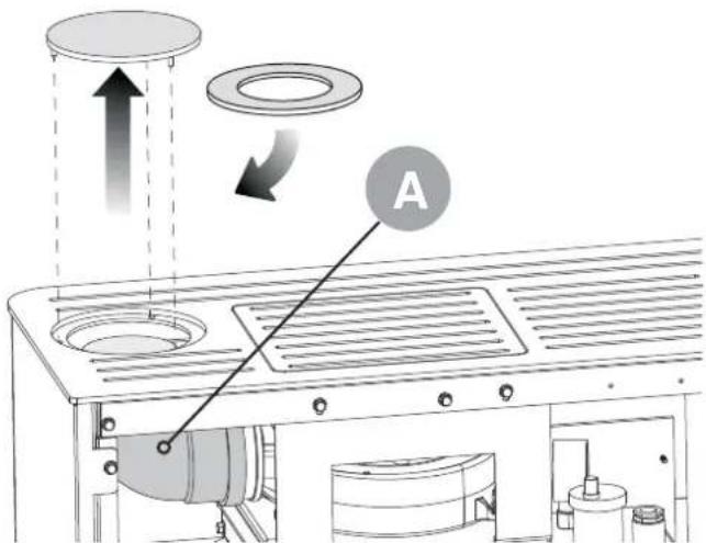
fig. 5.11
natural_image
Exploded view diagram of a computer chassis showing internal components like ventilation grilles, heat sinks, and fan compartments (no text or labels)fig. 5.12
natural_image
Technical line drawing of a mechanical assembly with a magnified inset showing a component detail (no text or symbols)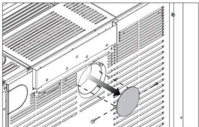
natural_image
Technical diagram of an air conditioner unit with cooling fans and ventilation grilles (no text or labels)fig. 5.16
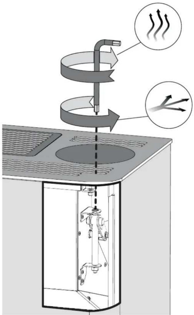
fig. 5.14
natural_image
Line drawing of a refrigerant air conditioner unit with airflow arrows indicating heat or airflow direction (no text or symbols)natural_image
Technical line drawing of a kitchen appliance with internal components and mounting brackets (no text or symbols)fig. 6.1
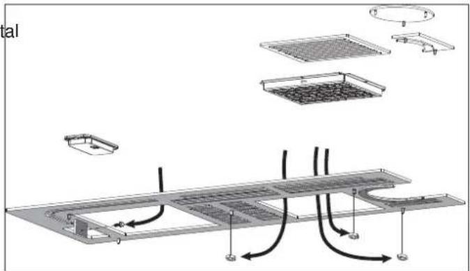
fig. 6.2
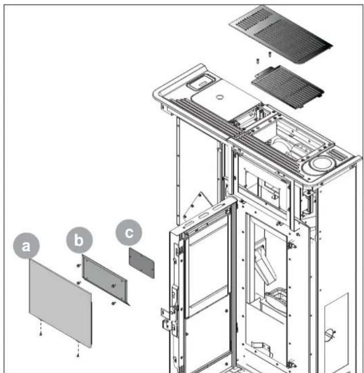
fig. 6.3
PROGRAMA DE CONTROL Y MANTENIMIENTO
natural_image
Simple line drawing of a trash bin with two crossed lines indicating no waste or restriction (no text or symbols)
PALAZZETTI
IL CALORE CHE PIACE ALLA NATURA
Palazzetti Lelio s.p.a.
Via Roveredo, 103
cap 33080 - Porcia (PN) - ITALY
Internet: www.palazzetti.it
Palazzetti accepts no liability for any mistakes in this handbook and is free to modify the features of its products without prior notice.

- DE
- MOVIMENTAZIONE E TRASPORTO
- INDEX
- INTRODUCTION
- SAFETY WARNINGS
- FUEL SPECIFICATIONS
- HANDLING AND TRANSPORT
- INSTALLATION
- MAINTENANCE
- DECOMMISSIONING AND DISPOSAL
- SYMBOLS
- INTENDED USE
- PURPOSEANDCONTENTSOFTHISMANUAL
- HOW TO KEEP THIS MANUAL
- STORAGE AND REFERENCE
- DAMAGE OR LOSS
- SALE OF THE STOVE
- UPDATES TO THE MANUAL
- GENERAL INFORMATION
- REQUESTING INFORMATION
- SPECIAL MAINTENANCE
- USE
- MAIN REFERENCE STANDARDS
- PRODUCT WARRANTY
- MANUFACTURER'S LIABILITY
- INTENDED USERS
- TECHNICAL SERVICE
- SPARE PARTS
- IDENTIFICATION LABEL
- DELIVERY OF THE STOVE
- INSTALLATION WARNINGS
- MAINTENANCE WARNINGS
- WARNINGS FOR THE USER
- FUEL SPECIFICATIONS
- The features of the pellets must comply with the requirements of EN 14961-2 (A1 or A2 category).
- STORING THE PELLETS
- REMOVING THE STOVE FROM THE PALLET
- GENERAL INFORMATION
- SAFETY PRECAUTIONS
- STOVE INSTALLATION SITE
- Dischargethroughroofusingatraditionalchimney
- SYSTEM CONNECTIONS
- Electrical connection
- Earth
- Connection to an external timer thermostat
- Connection to the smoke outlet (fig 5.11)
- Noah model:
- AIR DUCT
- IMPROVING THE COMBUSTION
- MAINTENANCE
- Servicing the flue system
- Servicing the stove
- ACCESS TO THE SMOKE FAN
- INHALT
- ALLGEMEINES VORWORT
- HANDLING UND TRANSPORT
- LUFTLEITUNG
- MANUTENTION ET TRANSPORT
- ENTRETIEN
- PRÉAMBULE
- MISE A JOUR DU MANUEL
- POÊLES DE LA GAMME "ETANCHE"
- CANALISATION DE L'AIR
- OPTIMISATION DE LA COMBUSTION
- ÍNDICE
- PREMISA GENERAL
- PALAZZETTI
Brand : Palazzetti
Model : Ecofire Ginger 9 air
Category : Frying Pan