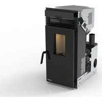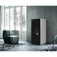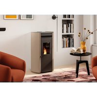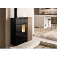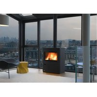
Ecofire Melita - Pan Palazzetti - Free user manual and instructions
Find the device manual for free Ecofire Melita Palazzetti in PDF.


User questions about Ecofire Melita Palazzetti
0 question about this device. Answer the ones you know or ask your own.
Ask a new question about this device
Download the instructions for your Pan in PDF format for free! Find your manual Ecofire Melita - Palazzetti and take your electronic device back in hand. On this page are published all the documents necessary for the use of your device. Ecofire Melita by Palazzetti.
USER MANUAL Ecofire Melita Palazzetti
9 PRIMA ACCENSIONE 28
natural_image
Diagram of a cylindrical device with labeled component A, showing internal structure and mounting points (no text or symbols beyond label)natural_image
Pile of cylindrical brown granules or pellets, labeled as Fig. 2 (no text on the particles themselves)text_image
Technical diagram of a device with numbered parts for identificationNINA
text_image
Technical diagram of a mechanical device with numbered components for identificationFig. 3
text_image
Diagram of a server rack with numbered components and wiring, labeled 1 to 7 for identification.Fig. 4
natural_image
Technical line drawing of a vertical cylindrical device with internal components and a top-mounted unit, showing height dimension 113159 (no text or symbols beyond measurement label)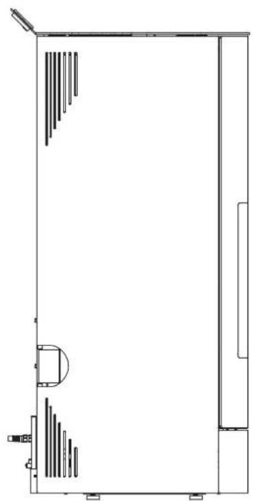
natural_image
Pure architectural floor plan lines without any text, numbers, or symbols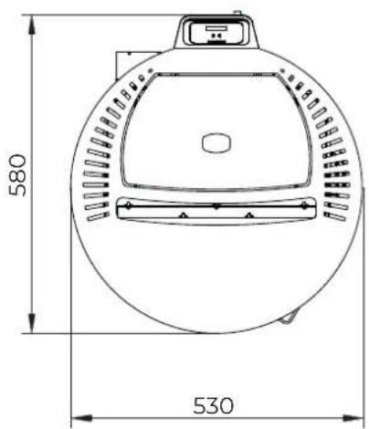
text_image
580 530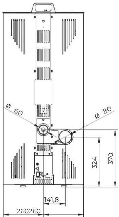
text_image
Ø 60 Ø 80 324 370 141,8 260260natural_image
Technical line drawing of a vertical cylindrical device with internal components and a top-mounted unit (no text or symbols)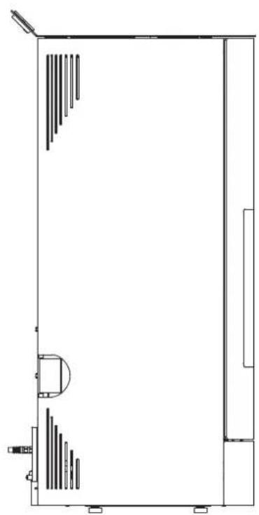
natural_image
Pure architectural floor plan lines without any text, numbers, or symbols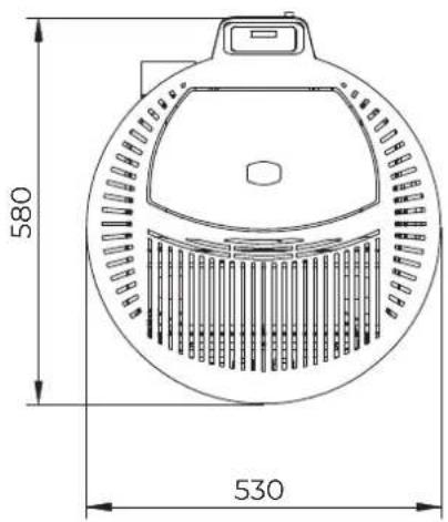
text_image
580 530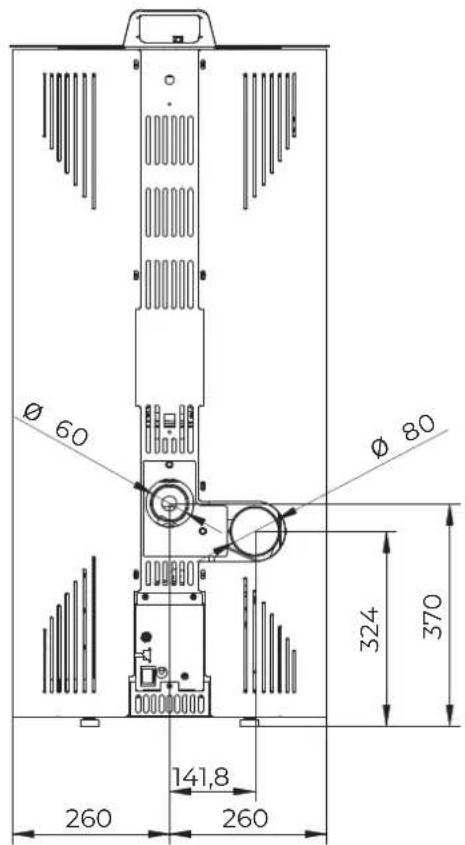
text_image
Ø 60 Ø 80 324 370 141,8 260 260natural_image
Technical illustration of a cylindrical device with internal components and directional arrows, showing assembly steps (no text or symbols)5.1 Trasporto

natural_image
Technical line drawing of a pipe fitting with a coiled cable, labeled Fig. 17 (no text or symbols on the diagram itself)natural_image
Illustration of a hand holding an electrical plug next to a wall-mounted switch (no text or symbols)
natural_image
Diagram of a kitchen appliance with a cutting tool inserted into a gridded tray (no text or symbols)- Caricare i pellet.
natural_image
Diagram of a food preparation setup with a griddle, basket, and tool (no text or symbols)natural_image
Technical line drawing of a mechanical device interior with pipes and housing (no text or symbols)natural_image
Symbol of a trash bin crossed with a diagonal line and a horizontal bar below (no text or labels)TABLE OF CONTENTS

User and Installer

Installer

1 GENERAL INTRODUCTION 37
1.1 Symbols 37
1.2 Intended use 37
1.3 Purpose and content of the manual 37
1.4 Preservation of the manual 37
1.5 Update of this manual 37
1.6 Overview 37
1.7 Compliance 38
1.8 Responsibility of the manufacturer 38
1.9 Technical assistance and maintenance 39
1.10 Spare parts 39
1.11 Serial plate 39
1.12 Delivery of the appliance 39
2 SAFETY WARNING 40
2.1 Warnings for the installer 40
2.2 Warnings for technical maintenance personnel 41
2.3 Warnings for users 41
3 FUEL CHARACTERISTICS 44
3.1 Fuel characteristics 44
3.2 Pellet storage 44
4 BECOMING FAMILIAR WITH THE PRODUCT 45
4.1 Description 45
4.2 Dimensions 47
4.3 Technical features 49
4.4 Serial plate 50
4.5 Wiring diagram 51

5 HANDLING AND TRANSPORTATION 52
5.1 Transportation 52
5.2 Checking the floor where the appliance will be placed 53
6 PREPARING THE PLACE OF INSTALLATION 53
6.1 General considerations 53
6.2 Safety Precautions 53
6.3 Place of installation 53
6.4 Combustion air 55
6.5 Flue gas fitting 56
6.6 Roof exhaust with traditional fireplace 57
7 INSTALLATION 58
7.1 General considerations 58
7.2 Levelling of the appliance 58
7.3 Electrical connection 58
7.4 Fuel optimisation 58
9.1 Pellet loading 60
9.2 First start up 60
10 MAINTENANCE 61
10.1 Maintenance of the smoke system 61
10.2 Appliance maintenance 61
10.3 Ordinary maintenance cleaning program 62
10.4 Ordinary cleaning 63
10.5 Ordinary maintenance 64
11 DEMOLITION AND DISPOSAL 66
1 GENERAL INTRODUCTION
Palazzetti heating appliances are manufactured and tested in accordance with the safety requirements set forth in the reference European directives.
Even partial printing, translation and reproduction of this manual are bound by the authorisation from Palazzetti. Technical information, graphical representations and specifications in this manual may not be disclosed to third parties.
Do not operate if not all the information provided in the manual has been thoroughly understood; if in doubt always request the advice or intervention of Palazzetti specialised personnel.
Palazzetti reserves the right to change specifications and technical and/or functional characteristics of the product at any time without prior notice.
1.1 Symbols
In this manual the points of major importance are highlighted by the following symbols:

INDICATION: Indications concerning the correct use of the appliance and the responsibilities of those in charge.

ATTENTION: The point in which a note of particular importance is expressed.

HAZARD: Expresses an important note of behaviour for the prevention of injuries or damage to property.
1.2 Intended use

The appliance, which is the subject of this manual, is an indoor domestic heating stove, powered exclusively by wood pellets with automatic loading.

The appliance must only work with the fire box door closed.
The intended use indicated is valid only for appliances in full structural, mechanical and engineering efficiency.
1.3 Purpose and content of the manual
The purpose of this manual is to provide the fundamental and basic regulations for correct installation of the appliance.
Strict observance of that which is described herein guarantees a higher level of appliance safety and productivity.
1.4 Preservation of the manual
Preservation and consultation
The manual must be kept carefully and must always be available for consultation, both by the user and by the assembly and maintenance staff.
The installation manual is an integral part of the appliance.
Deterioration or loss
If needed, request an additional copy from Palazzetti.
Sale of the appliance
In the event of transferring the appliance the user is obliged to deliver even this manual to the new owner.
1.5 Update of this manual
This manual reflects the latest developments at the time the appliance was placed on the market.
The products already on the market with the relevant technical documentation, will not be considered by Palazzetti as deficient or inadequate due to possible modifications, adjustments or application of new technologies on newly marketed products.
1.6 Overview
The instructions in this manual apply as general rules; it is still necessary to comply with all the rules laid down by the local, national and European legislation in force in the country where the appliance is installed.
Information
In the event that you need to contact the Manufacturer of the appliance, refer to the serial number and the identification data indicated on the identification plate.
In case of problems, contact the dealer or a qualified technician authorised by the manufacturer; in case of repair, request the use of original spare parts.
Periodically check and clean the flue gas duct (connected to the chimney flue).
The pellet stove is not a cooking device.
Store this instruction manual, which is an integral part of the stove, for its entire service life. If the stove is sold or transferred to another user, always make sure it is accompanied by the product booklet.
In case of loss, contact the manufacturer or authorised retailer to receive another copy.
Maintenance
Maintenance operations must be carried out by qualified personnel authorised to work on the appliance to which this manual refers.
Responsibility for the works of installation
Responsibility for the works carried out for the installation of the appliance cannot be considered to be taken on by Palazzetti; it is and remains the responsibility of the installer, who is responsible for carrying out the checks relating to the flue, the air intake and how right the proposed installation solutions are.
1.7 Compliance
The appliances covered by this manual comply with the legislative provisions of the following European directives:
2014/30/EU: Electromagnetic Compatibility Directive
2014/35/EU: Low Voltage Directive
2017/2102/EU: RoHS Directive
2009/125/EC: Ecodesign Directive – Energy related product
2014/53/EU: RED (Radio Equipment Directive)
REGULATION (EU) N. 305/2011 (CPR)
REGULATION (EU) 2015/1185 (ECODESIGN)
The following harmonised standards and/or regulations have been applied:
EMCD:
- EN 55014-1:2017
- EN 61000-3-2:2015
- EN 61000-3-3:2014 /EC:2016
- EN 55014-2:2015
EMF:
- EN 62233:2008 / EC:2008
LVD:
- EN 60335-1:2013 /EC:2014 /A11:2015 /A13:2017
- EN 60335-2-102:2007 /A1:2011
CPR:
- EN 14785:2006
1.8 Responsibility of the manufacturer

With the delivery of this manual, Palazzetti declines all responsibility, both civil and criminal, direct or indirect, due to:
- installation that does not comply with standards in force in the country and with safety directives;
- partial or total non-compliance with the instructions contained in this manual;
- installation by unqualified and/or untrained personnel;
- use not in compliance with the safety directives;
- modifications and/or repairs carried out on the appliance that are not authorised by the manufacturer;
- lack of maintenance;
- exceptional events.
1.9 Technical assistance and maintenance
Palazzetti has a dense network of service centres with specialised, trained and skilled technicians.
The headquarters and our sales network is at your disposal to direct you to the nearest authorised service centre.
1.10 Spare parts
Use only original spare parts.
Do not wait until the components are worn by use before proceeding to their replacement.
Replace a worn component before its breaking favours the prevention of accidents arising from accidents caused by the sudden breakage of components which may cause serious damages to persons and objects.
1.11 Serial plate
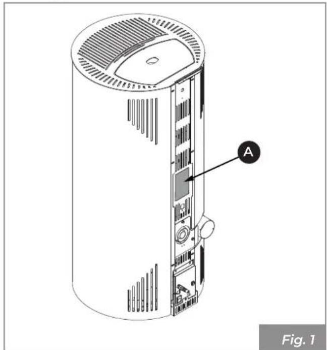
The serial identification plate (A) is positioned on the rear (Fig. 1) and shows all the characteristic data relating to the appliance, including details of the Manufacturer, the Serial number and brand C€
natural_image
Diagram of a cylindrical device with labeled component A, showing internal structure and mounting points (no text or symbols beyond label)The Serial number must always be indicated for any type of request regarding the appliance.
1.12 Delivery of the appliance
The appliance is delivered perfectly packaged and fixed to a wooden platform which allows handling it using fork lift trucks and/or other means.
The following material accompanies the appliance:
- manual for use, installation and maintenance;
- bar code label;
- display booklet;
2 SAFETY WARNING
2.1 Warnings for the installer
Observe the prescriptions contained in this manual.

The instructions for assembly and disassembly of the appliance are reserved for specialist technicians only.
The installation, use and maintenance of the product must be in accordance with the manufacturer's instructions and in compliance with the regulations. Failure to comply with the instructions and any incorrect operations may give rise to hazardous situations, damage to property, animals, health problems or malfunctioning.
Installation, electrical connection, operational testing and maintenance must be carried out exclusively by authorised and qualified personnel.
The installation and maintenance of the product must be carried out exclusively by qualified personnel with suitable knowledge of the product itself. Use only original spare parts recommended by the manufacturer.
Responsibility for the works carried out in the location of the appliance is, and remains, with the user; the latter is also responsible for carrying out the checks relating to the proposed installation solutions.
The installer must comply with all local, national and European safety regulations.
The appliance must be installed on floors with adequate load bearing capacity.

Check that the chimney flue and air inlet set-ups conform to the type of installation.
Do not carry out on-the-fly electrical connections with temporary or uninsulated cables.
Check that the earthing of the electrical system is efficient.
Before starting the assembly or dis- assembly phases of the appliance, the installer must observe the safety precautions required by law and the following indications in particular:
- do not operate in adverse conditions;
• they must operate in perfect psychophysical conditions and must check that the personal protective equipment is intact and functioning perfectly; - they must wear gloves and safety shoes;
- they must use tools with electrical insulation;
- they must make sure that the area used during assembly/dismantling is free from obstacles.
The product must only be installed in rooms that are not at risk of fire and equipped with all the necessary services including air and electrical supplies and smoke exhausts.
Evaluate the static conditions of the surface bearing the weight of the product and provide suitable insulation if it is composed of flammable materials (e.g. wood, carpet, plastic).
Live electrical parts: power the product only once it has been completely assembled.
2.2 Warnings for technical maintenance personnel
Maintenance operations must be carried out only by authorised and qualified personnel.
Observe the prescriptions contained in this manual.
Always use personal protective equipment and other means of protection.
Before starting any maintenance work ensure that the appliance, if it has been used, has cooled down.
Even if only one of the safety devices is not working, the appliance is to be considered not working.
Disconnect the appliance from the mains before carrying out any maintenance operations.
Disconnect the appliance from the electrical mains before working on electrical and electronic parts, connectors and moving parts (pellet loading systems, automatic burn pot cleaning systems, etc.).
2.3 Warnings for users
To ensure correct use of the product and electronic appliances connected thereto and to prevent accidents, it is important to always follow the instructions provided in this manual.
The appliance has particularly hot external surfaces (door, handle, glass, smoke outlet pipes, etc.). Contact with these parts must therefore be avoided unless wearing suitable protective clothing or equipment, such as heat resistant gloves or in the presence of "cold handle" operating systems.
For this reason, maximum caution is recommended during operation and in particular:

Do not touch and do not get close to the glass of the firebox door, it may cause burns, do not look at the flame for a long time.

Do not hang laundry directly over the appliance for drying: fire hazard.

· do not touch the smoke outlet;
· do not perform any type of cleaning;
• do not remove the ashes;
- do not open the firebox door;
- do not open the ash drawer (where provided).
The appliance cannot be used by children under the age of 8 and by people with reduced physical, sensory or mental abilities, or without experience or the necessary knowledge, unless they are under supervision or after they have received instructions relating to the safe use of the appliance and to understanding the inherent dangers. Children must not play with the appliance. Cleaning for which the user is
responsible must not be carried out by unsupervised children.
Before performing any type of operation, the user or whoever is operating the product must have read and fully understood the contents of this installation and use manual. Errors or bad settings may cause hazardous conditions and/or irregular operation.
Unskilled users must be protected from access to any part that could expose them to danger. Therefore, they must not be allowed to intervene on internal parts at risk (electrical or mechanical), even if the disconnection of the power supply is required.
Respect the instructions and warnings highlighted on the sign plates displayed on the appliance.
The sign plates are accident prevention devices, therefore they must always be perfectly legible. If these are damaged and unreadable, it is mandatory to replace them, requesting the original spare parts from the Manufacturer.
Follow the routine and extraordinary maintenance schedule carefully.
Do not use the appliance without having first carried out daily cleaning.
Do not use the appliance if operation is abnormal, you suspect a breakage or if there are unusual noises.
In case of failure or malfunction, turn the appliance off and immediately contact your specialised technician.
Do not throw water on the appliance in operation or to extinguish the fire in the burn pot.
Do not switch the appliance off by disconnecting the mains electrical connection.
Do not lean on open doors, this could compromise the stability of the appliance.
Do not use the appliance as an anchor support of any kind.
It is prohibited to use the product as a ladder or support structure.
Do not clean the appliance until the structure and ashes have completely cooled.
Only touch the door when the appliance is cold.
In case of flue gas leaks in the room or explosions detrimental to the device, turn it off, ventilate the room and immediately contact your installer/service technician.
In case of fire in the chimney flue, turn the appliance off, disconnect it from the power supply and do not open the door. Then call the competent authorities.
In case of failure of the ignition system, do not ignite the appliance with flammable materials.
In electrically powered devices, if unburned gas/fumes accumulate inside the fire box, do not disconnect the electrical power supply and move as far away from the appliance as possible.
In case of malfunction of the appliance due to a poor flue draught, clean the flue in accordance with the procedure described in section "10.1 Maintenance of the smoke system" on page 61.
Do not touch the painted parts during operation to avoid damage to the paintwork.
All responsibility for improper use of the product is fully borne by the user, who relieves the manufacturer of any civil and criminal liability.

It is prohibited to operate the appliance with the door open.
It is prohibited to use the appliance if the door glass or gaskets are damaged.
Any type of unauthorised handling or replacement with non-original spare parts shall place the safety of the operator at risk and relieve the manufacturer of any civil and criminal liability.

It is prohibited to manually load pellets into the burn pot; this type of incorrect behaviour may generate an abnormal amount of unburned gas, giving rise to the risk of explosion inside the chamber.
Unburned pellet deposits in the burn pot after a failed ignition must be removed before making a new ignition attempt.
If the burn pot is not cleaned and regularly serviced, malfunctions and explosions may occur inside the appliance. Be sure to remove all traces of material and deposits from the holes of the burn pot and to clean them each time the ash is emptied or after each failed ignition attempt. Make sure the burn pot holes don't decrease in size as this may have a negative effect on the safe operation of the appliance.
Do not wash the product with water. Water may infiltrate the unit and damage the electrical insulation, causing electric shocks.
Do not sit/stand in front of the product in operation for long periods.
Incorrect use of the product or incorrect maintenance works may create a serious risk of explosion in the combustion chamber.
Only use the fuel recommended by the manufacturer. The product must never be used as an incinerator.
It is prohibited to use benzene, lamp fuel, kerosene, liquid firelighter for wood, ethyl alcohol or similar liquids to light or rekindle a flame in this appliance. Keep these liquids at a due distance from the appliance during
operation.
It is prohibited to insert other types of fuels in the tank other than wood pellets.
Some tips to avoid corrosion phenomena:
- carry out routine cleaning operations to avoid the build-up of ash deposits;
- feed the appliance only with fuel having the characteristics described in the section "Fuel characteristics";
- Do not use solvents, acids, aggressive detergents or products to directly clean the glass or other components of the product;
- avoid leaving the product in unfavourable ambient conditions (humidity, airborne salinity, storms, etc.);
- if the appliance is not used for long periods (e.g. during the summer), disconnect the combustion air inlet pipe and place dessicant bags in the combustion chamber to absorb the humidity in the air, making sure to remove them when the product is re-ignited.
3 FUEL CHARACTERISTICS
3.1 Fuel characteristics
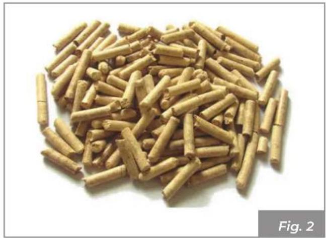
The pellet (Fig. 2) is a compound made from various types of wood pressed together with mechanical procedures in compliance with environment protection regulations, and it is the only fuel required for this type of appliance.
natural_image
Pile of cylindrical brown granules or pellets, labeled as Fig. 2 (no text on the particles themselves)The efficiency and thermal potential of the appliance may vary according to the type and quality of the pellets used.
We recommend the use of class A1 pellets (ISO 17225-2 standard, ENplus A1, DIN Plus or NC 444 category "High Performance NF Pellets Biofuel Quality").

Use pellets with standard length between 3 and 40 mm.

Using poor quality pellets or pellets that do not comply with the manufacturer's indications may compromise the normal operation of the appliance, cause damage (including aesthetic damage) to the product and result in the warranty being voided.
The appliance is equipped with a pellet storage tank having the capacity indicated in table "4.3 Technical features" on page 49.
The loading compartment is positioned at the top, it must always be open for loading of the pellets and must remain closed while the appliance is operating.

It is prohibited to use the appliance as an incinerator to burn rubbish.
3.2 Pellet storage

Pellets must be kept in a dry place, not too cold and the bags must be kept sealed.
It is advisable to keep a number of bags of pellets in the room where the appliance is being used or in an adjacent room provided it is at the correct temperature and humidity and at a safe distance (at least one meter) away from heat sources.
Wet and/or cold pellets (5 °C) reduce the thermal potential of the fuel resulting in the need for more cleaning maintenance of the burn pot (unburned material) and of the fire box.

Pay particular attention to the storage and handling of pellet bags. Their crushing and the formation of sawdust must be avoided.
If sawdust is placed in the appliance tank it could cause the pellet loading system to block.
4 BECOMING FAMILIAR WITH THE PRODUCT
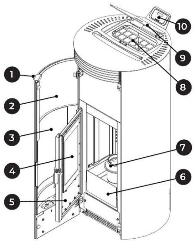
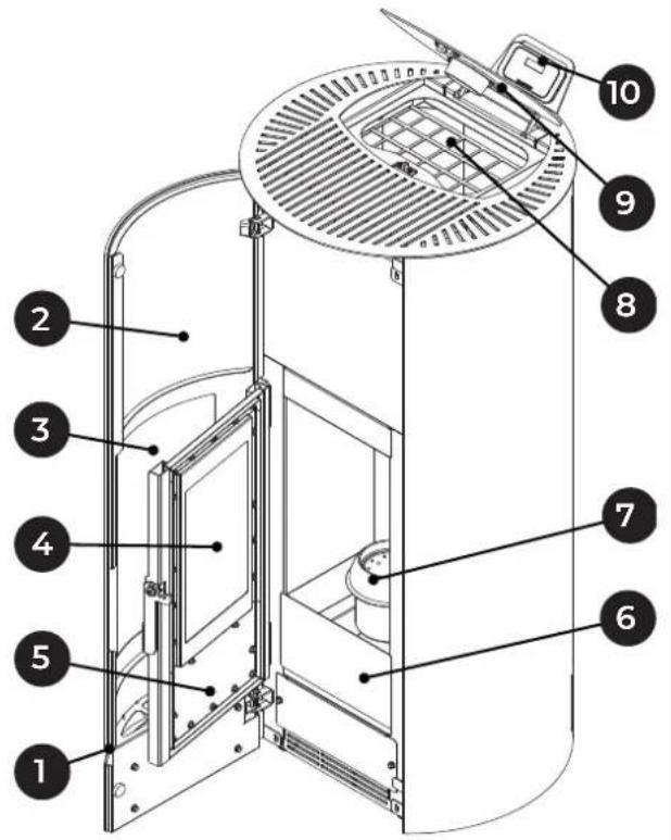
4.1 Description
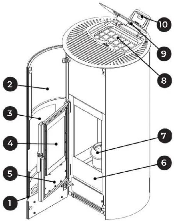
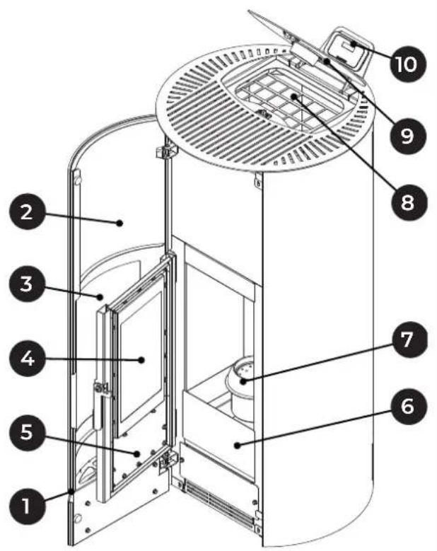
MELITA
text_image
Technical diagram of a device with numbered components for identificationNINA
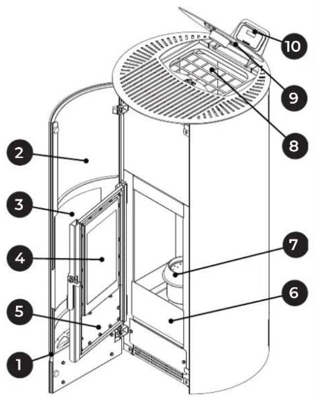
text_image
Technical diagram of a vertical furnace or oven with numbered components for identificationFig. 3
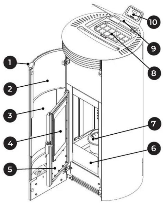
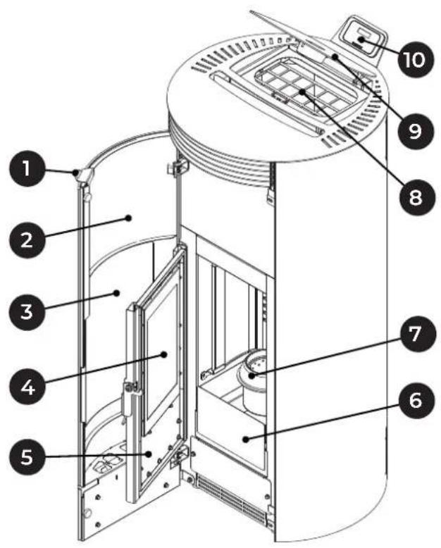
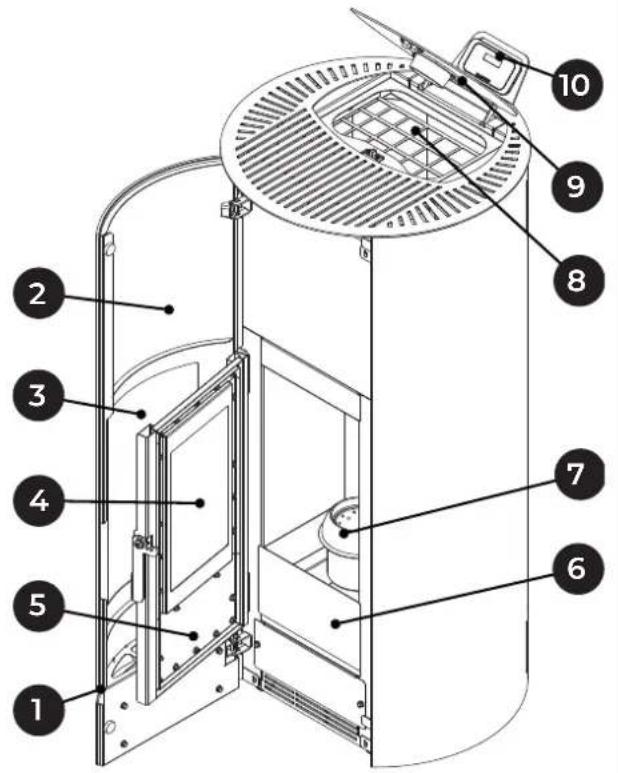
1 Opening handle
2 Aesthetic door
3 Aesthetic door glass
4 Technical door glass
5 Fire box technical door
6 Ash drawer
7 Burn pot
8 Pellet hopper
9 Tank lid
10 Display
10 Display
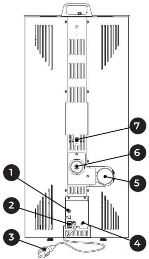
text_image
Diagram of a server rack with numbered components for identificationFig. 4
| 1 Room sensor |
| 2 Power switch |
| 3 Power cable |
| 4 Manual reset thermostat |
| 5 Flue gas pipe |
| 6 Combustion air inlet |
| 7 RJ11 connector |
4.2 Dimensions
MELITA
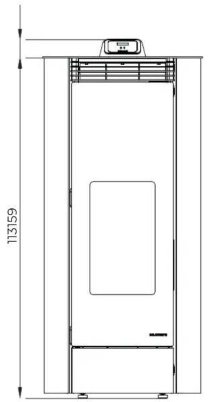
natural_image
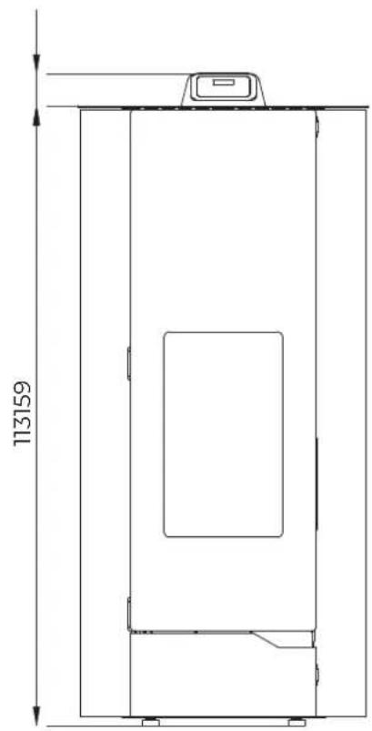
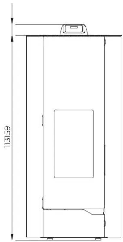
Technical line drawing of a vertical cabinet or enclosure with height dimension labeled 113159 (no text or symbols beyond the label)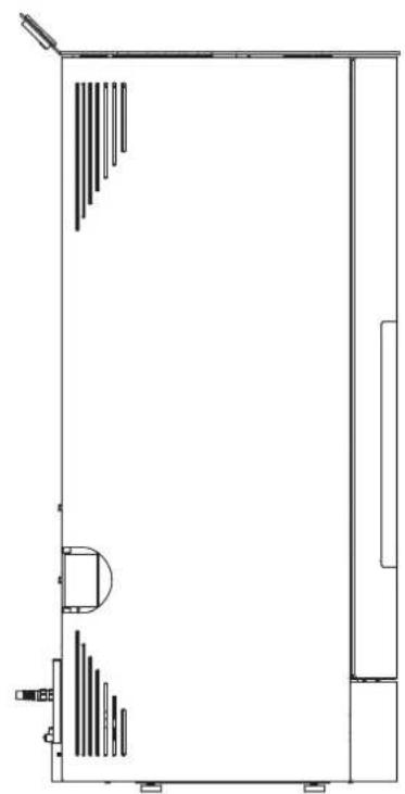
natural_image
Pure architectural floor plan lines without any text, numbers, or symbols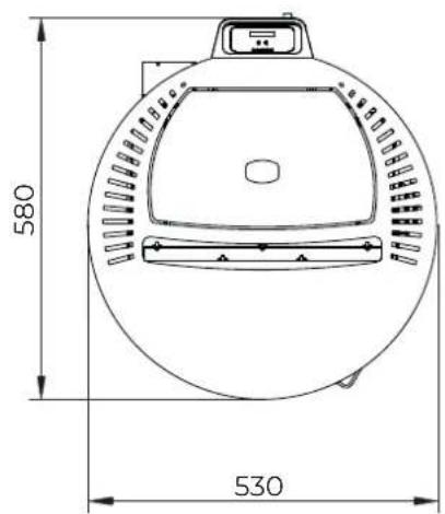
text_image
580 530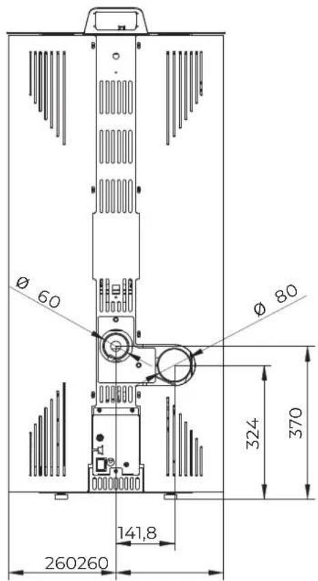
text_image
Ø 60 Ø 80 324 370 141,8 260260∅ 60 combustion air inlet
∅ 80 flue gas outlet
Dimensions in mm
Fig. 5
NINA
natural_image
Technical line drawing of a vertical cylindrical device with internal components and a top-mounted unit (no text or symbols)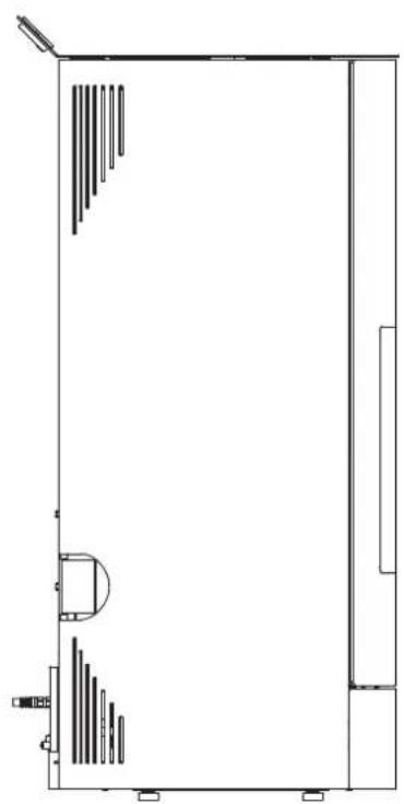
natural_image
Pure architectural floor plan lines without any text, numbers, or symbols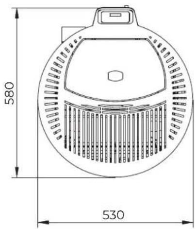
text_image
580 530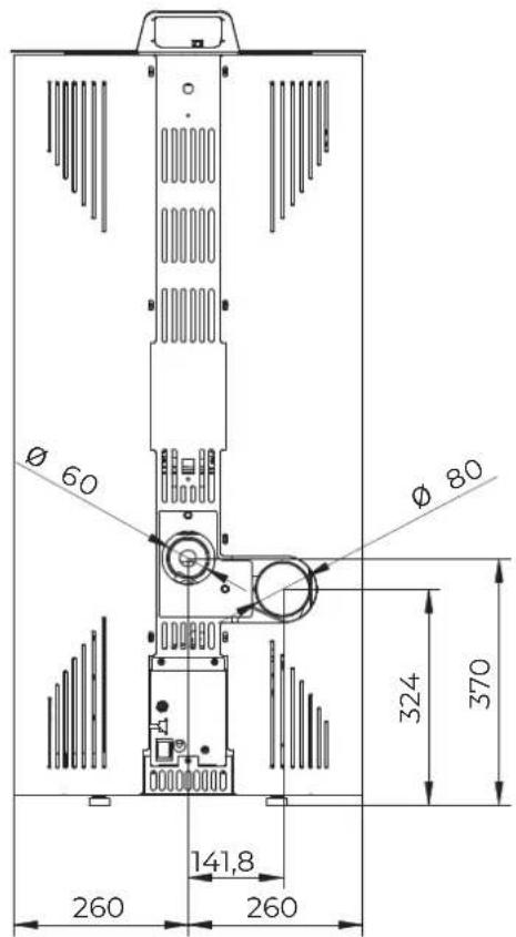
text_image
Ø 60 Ø 80 324 370 141,8 260 260∅ 60 combustion air inlet
∅ 80 flue gas outlet
Dimensions in mm
Fig. 6
4.3 Technical features
| MELITA - NINA | MELITA 6NINA 6 | MELITA 8NINA 8 | |||
| Min Max | Min Max | ||||
| Overall thermal power (output) kW 2,9 6 2,9 8,2 | |||||
| Yield | % | 92,3 | 90 | 92,3 | 87,7 |
| Flue gas temperature | °C | 85,8 | 167,9 | 85,8 | 224,5 |
| Flue gas flow rate | g/s | 3,47 | 4,1 | 3,47 | 5,1 |
| Hourly fuel consumption | kg/h | 0,628 | 1,36 | 0,628 | 1,917 |
| CO emissions (at 13% of O2) | mg/Nm3 | 151 | 26 | 151 | 26 |
| Flue gas outlet | mm | ∅ 80 | |||
| Combustion air inlet | mm | ∅ 60 | |||
| Outside air intake | mm | ∅ 100 | |||
| Fuel | Wooden pellets | ||||
| Flue draught | Pa | 12 (±2) | |||
| Minimum draught for chimney sizing | Pa | 0,0 | |||
| Stove suitable for rooms no smaller than | m3 | 30 | |||
| Feeding tank capacity | kg | 18 | |||
| Weight | kg | 92 | |||
| No. rear fans | no. | - | |||
| Rear fan flow rate | m3/h | - | |||
| Electrical data | MELITA 6NINA 6 | MELITA 8NINA 8 | |
| Voltage | V | 230 | |
| Frequency | Hz | 50 | |
| Max power absorbed during operation | W | 80 | |
| Power absorbed at electric ignition | W | 380 | |
4.4 Serial plate
Palazzetti Lelio S.p.A. - via Roveredo 103 - 33080 Porcia (PN)

DOP Nr. 000001385 - N.B. 2468 EN 14785:2006
| F | Fuel |
| Plmax | Max. thermal power input |
| Plmin | Min. thermal power input |
| Pmax | Rated thermal power |
| Pmin | Reduced thermal power |
| EFFmax | Efficiency at rated power |
| EFFmin | Efficiency at reduced power |
| COmax | CO emissions at rated power (13% O_2 ) |
| COmin | CO emissions at reduced power (13% O_2 ) |
| Dust | Dust at rated power (13% O_2 ) |
| Tf | Flue gas temperature |
| X1/X2/Y | Minimum distance from flammable materials |
| V | Voltage |
| f | Frequency |
| Wmin | Max power absorbed during operation |
| Wmax | Max power absorbed during ignition |
4.5 Wiring diagram
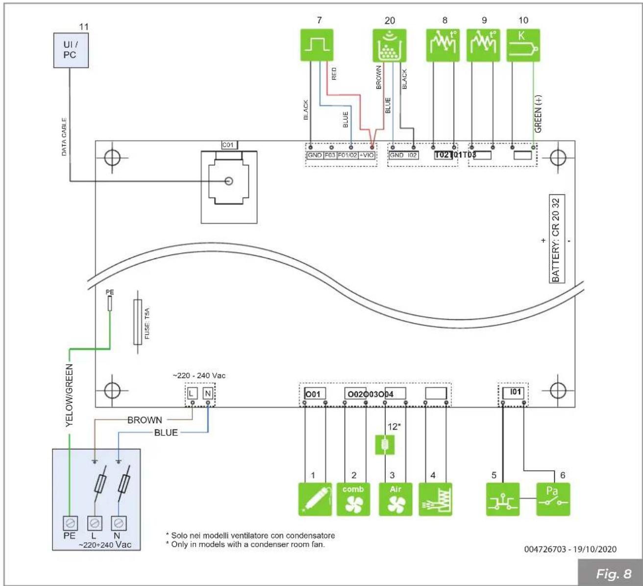
text_image
UI / PC DATA CABLE C01 7 20 8 9 10 GREEN (+) GND F03 F01/02 -VIO GND I02 T02 T01 T03 + BATTERY: CR 20 32 PE FUSE TSA ~220 - 240 Vac BROWN BLUE YELLOW/GREEN PE L N ~220*240 Vac O01 O02 O03 O04 1 2 3 4 5 6 comb Air Pa * Solo nei modelli ventilatore con condensatore * Only in models with a condenser room fan. 004726703 - 19/10/2020 Fig. 8| 1 | Incandescence resistance | |
| 2 | Flue gas exhaust fan | |
| 3 | Room fan | |
| 4 | Loading dispenser | |
| 5 | STB Safety | |
| 6 | Low pressure safety | |
| 7 | Hall sensor |
| 8 | Pellet probe | |
| 9 | Room sensor | |
| 10 | Flue gas probe | |
| 11 | Control panel | |
| 12 | Inductance | |
| 20 | Pellet sensor |
5 HANDLING AND TRANSPORTATION
The appliance is delivered complete with all the parts required.
Pay attention to the tendency for the appliance to become unbalanced.
The centre of gravity of the appliance is carried towards the front.
Bear in mind the above also when moving the appliance on the transport stand. It is advisable to unpack the appliance only when it has arrived at the installation site.

The product must be handled and unpacked using suitable means.
Make sure that children do not play with the packaging components (e.g. films and polystyrene):

Danger of suffocation!
During moving, lifting, and unpacking of the appliance the following is absolutely necessary:
• always keep it upright;
- never tip it over into a horizontal position;
- never tilt it on the front to avoid breaking the glass of the fire box door.
- Removal of the transport pallet
Disposal can be entrusted to a third party, provided only companies authorised for the recovery and elimination of the materials in question are used.
Always follow the regulations in force in the country in which the appliance is being used for disposal of materials and possibly for the disposal report.
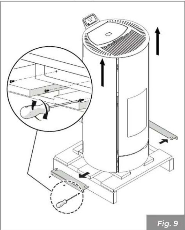
To remove the appliance from the transport pallet:
- Unscrew the side fixing screws
- Remove the fixing brackets
- Lift the appliance
- Remove the transport pallet
natural_image
Technical illustration of a cylindrical device with internal components and directional arrows, showing assembly steps (no text or symbols)5.1 Transportation

Make sure that the lifting carriage has a payload higher than the weight of the appliance to be lifted. The full responsibility of the lifting of loads lies with the person handling the lifting equipment.

Ensure wood or timber floors are properly protected in order to prevent the weight of the appliance from damaging them during movement.
During lifting, avoid jerking or abrupt movements.
Pay attention to overbalancing.
5.2 Checking the floor where the appliance will be placed
Check the load capacity of the floor slab.
If a floor is not suitable for supporting the weight of the appliance, install appropriate steel plates (A - Fig. 10) or concrete base (A - Fig. 11) equipped with 10x10x6 electro-welded mesh (B - Fig. 11) to distribute the weight.

For the dimensions of the plates and the concrete base, use a qualified technician.
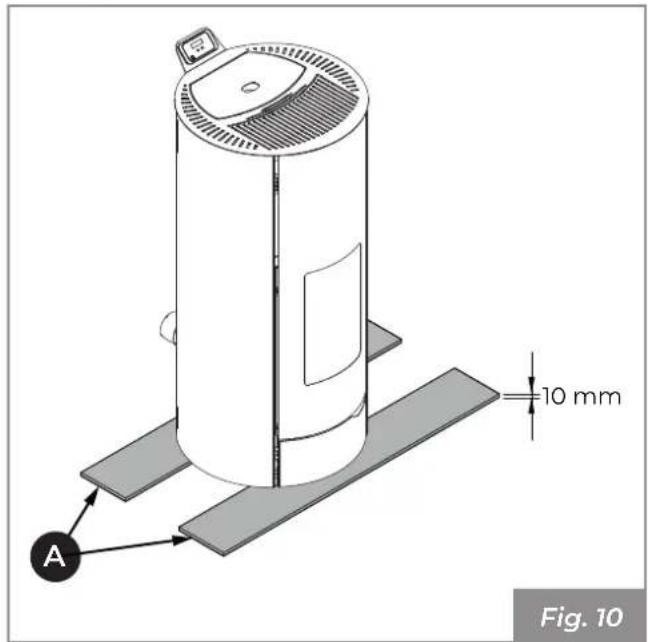
text_image
A 10 mm Fig. 10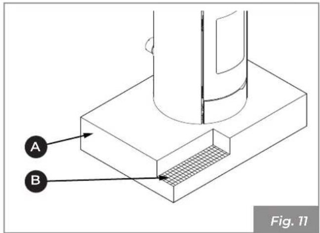
text_image
A B Fig. 116 PREPARING THE PLACE OF INSTALLATION
6.1 General considerations
The following paragraphs contain some guidelines to be followed to obtain the maximum efficiency of the product purchased and to ensure safe operation. The following indications are however subject to compliance with any possible national, regional and municipal laws and regulations in force in the country where the appliance is installed.
In Italy, installation must be performed by qualified personnel in compliance with the EN 10683 standard.
6.2 Safety Precautions
The operations for assembly and disassembly of the appliance are reserved for specialist technicians only.
It is recommended to be sure of their qualifications and their actual capacity.

For Italy, these technicians must be in possession of the letter "C" qualification issued by the chamber of commerce based on the Ministerial Decree. 37/08.
6.3 Place of installation
For the minimum distances that must be respected when positioning the appliance with respect to flammable materials and objects, refer to the instructions in Fig. 12.

text_image
Z Y2 X2 X1 Y1 Fig. 12| Model X1 | X2 Y1 | Y2 Z | ||||
| MELITA | 800 | 150 200 | 200 | 600 mm | ||
| NINA | 800 | 150 | 200 | 600 mm |
Floors made of flammable material such as wood, parquet, linoleum, laminate or floors covered with carpets must be protected by a fireproof base under the appliance that also protects the front during cleaning from any falling burning residues.
The manufacturer declines all responsibility for any variations in the characteristics of the material constituting the floor under the protection.

Set up an accessible technical space for any maintenance work.
Remember to respect the minimum distance from flammable materials (X), shown on the identification plate of the pipes used to make the chimney (Fig. 13).
Pi = Flammable wall
Pp = Floor protection
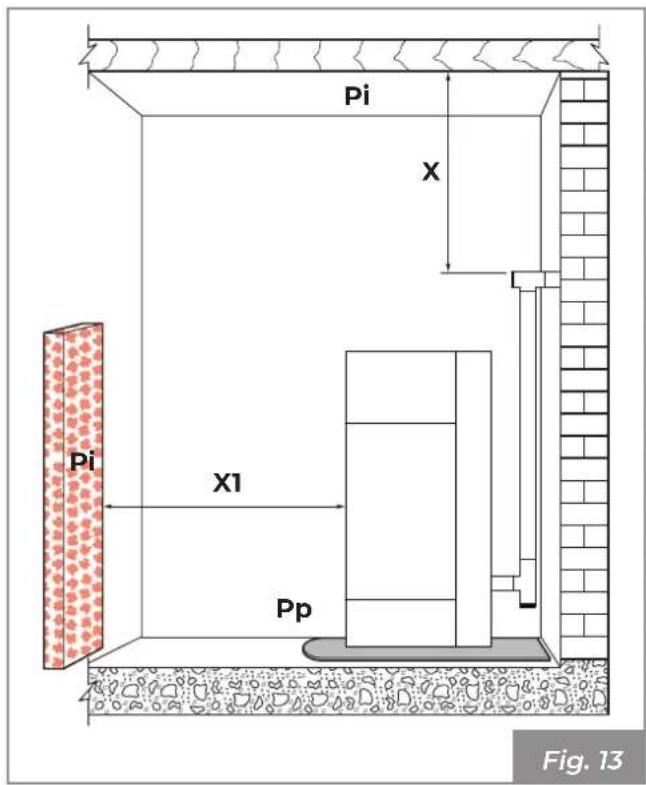
text_image
Pi X Pi X1 Pp Fig. 13Set up the electricity supply line to arrive near the appliance for the connection of the power cable.
6.4 Combustion air
The appliance, during its operation, requires combustion air.
The inflow of combustion air can be obtained in the following ways:
- it can come directly from outside with direct connection to the combustion chamber (Fig. 14).
- it can come from the installation room or suitable adjacent rooms (Fig. 15)
Extraction of combustion air from outside
Connect the combustion air inlet of the appliance to the air intake using a special pipe (Fig. 14).
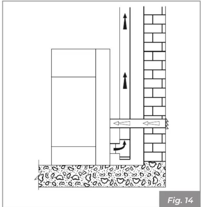
text_image
Fig. 14Extraction of combustion air in the room
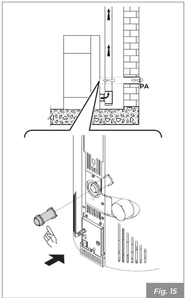
Create the air intake on the wall (Fig. 15 - PA = Air Intake), and leave the appliance to withdraw the room air, making sure to connect the provided pipe on the air inlet pipe, to prevent any resonance effects.
text_image
PA Fig. 15If the rear wall of the appliance is an external wall, make a hole for the intake of combustion air at a height of about 20-30 cm from the ground, respecting the dimension indications given on the technical data sheet at "4.3 Technical features" on page 49.
A non-closable permanent aeration grid must be placed externally; in areas that are particularly windy and exposed to weathering, provide rain and wind protection.
Ensure that the air intake is positioned so that it won't be accidentally obstructed.
If it is impossible to create an external air intake in the wall behind the appliance (non-perimeter wall), a hole must be made in an external wall of the room where the appliance is positioned.
If it is not possible to create the fresh air intake in the room, an external hole can be created in an adjacent room provided it is permanently interconnected by means of a transfer grille.
It is prohibited to withdraw combustion air from a garage, warehouse containing combustible materials or rooms at risk of fire.

If one or more extraction fans (extractor hoods) are present and operating in the installation room, combustion malfunctions may occur due to lack of combustion air.
The combustion air intakes must therefore be correctly sized in order to guarantee the necessary supply of air for the correct operation of all devices.
6.5 Flue gas fitting
The appliance works with the combustion chamber at negative pressure. It is therefore essential to make sure that the flue gas evacuation is airtight (this is the responsibility of the installer).
The appliance must be connected to its own flue gas duct, not shared, and which is suitable for ensuring adequate dispersion of the combustion products into the atmosphere, in accordance with the regulations in force in the country of installation.

The components making up the flue gas ducting system must be declared suitable for the specific operating conditions and provided with CE marking.

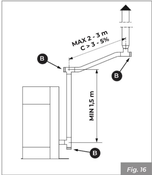
It is mandatory to create a first vertical section measuring at least 1.5 meters to guarantee correct expulsion of the flue gases.
It is advisable to make a maximum of 3 direction changes, in addition to that resulting from the rear connection of the appliance to the chimney, using 45 - 90° bends or Tee fittings (Fig. 16).
Always use a Tee fitting with inspection cap at each horizontal and vertical change of the flue gas route (Fig. 16).
The horizontal sections must have a maximum length of 2-3 m with an upward slope of 3-5% (Fig. 16).
Anchor the pipes with suitable collars to the wall.
The flue gas fitting MUST NOT BE connected:
- to a chimney used by other generators (boilers, stoves, fireplaces, etc. ...);
- to air extraction systems (hoods, vents etc. ...) even if "ducted".
It is forbidden to install shut-off and draught valves.
text_image
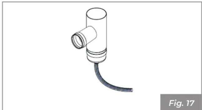
MAX 2 - 3 m C > 3 - 5% MIN 1,5 m Fig. 16On the first vertical tee, at the flue gas outlet of the appliance, a pipe must be connected at the bottom to drain any condensate that may form in the chimney (Fig. 17).
natural_image
Technical illustration of a pipe fitting with a coiled cable, labeled Fig. 17 (no text or symbols on the diagram itself)6.6 Roof exhaust with traditional fireplace
The chimney for the evacuation of flue gases must be made by qualified personnel in compliance with standards UNI 10683- EN 1856-1-2- EN 1857-EN 1443- EN 13384-1-3- EN 12391-1 both in terms of the dimensions and the materials used in its construction.
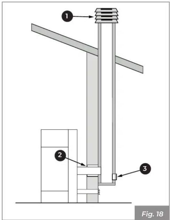
The evacuation of flue gases via a traditional chimney (Fig. 18) can be done as long as you are sure of the state of maintenance of the chimney. In the case of an old chimney, it is advisable to renew it using ducting.
The flue gas exhaust must be on the roof.
text_image
① ② ③ Fig. 181) Wind-proof cowl
2) Seal
3) Inspect

If the chimney has a larger section, it must be "intubated" with a suitably insulated steel pipe (with diameter suitable for the route) (Fig. 19).
Make sure that the connection to the brickwork chimney is properly sealed.

In case of pipes that pass through wooden roofs or walls, it is recommended to use special certified ducting kits commonly available on the market.
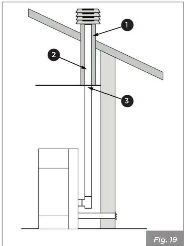
text_image
1 2 3 Fig. 191) Non-combustible material
2) Steel piping
3) Closing panel
7 INSTALLATION
7.1 General considerations
In the following paragraphs some indications are provided to be respected in order to obtain the maximum performance from the purchased product.

The following indications are how- ever subject to compliance with any possible national, regional and mu- nicipal laws and regulations in force in the country where the appliance is installed.
7.2 Levelling of the appliance
The appliance must be levelled with the help of a spirit level, by regulating the adjustable feet (Fig. 20).
A = Spirit level.
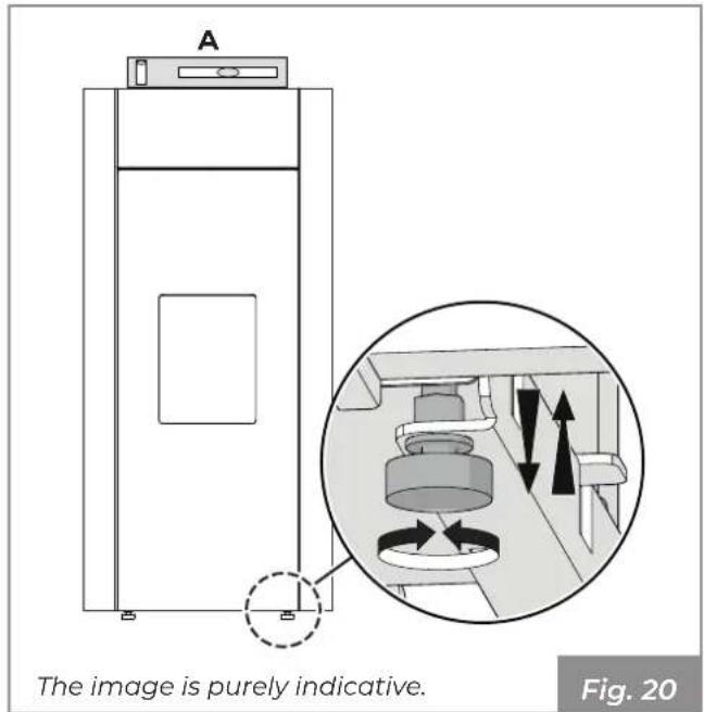
text_image
A The image is purely indicative. Fig. 207.3 Electrical connection
Simply connect the appliance to the electrical system using the supplied plug (Fig. 21).
The electrical connection (plug) must be easily accessible after appliance installation as well.

If the power supply cable is damaged it must be replaced by the technical assistance service or a qualified technician in order to prevent any risk.
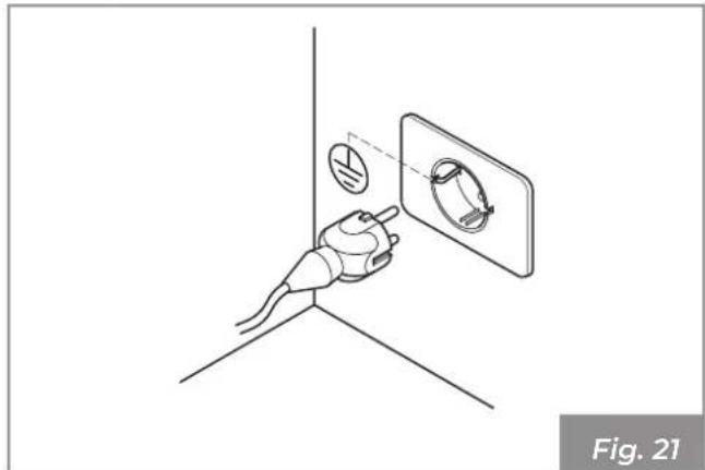
natural_image
Diagram of a hand holding a device near a wall-mounted screen, with no visible text or symbols
The system must be equipped with an earth connection and a differential switch in compliance with the laws in force.

The flue gas evacuation duct must be equipped with its own earth connection.
7.4 Fuel optimisation
Excellent fuel depends on different factors (type of installation, operating and maintenance conditions, type of pellets, etc.)
Upon first ignition, the stove can be regulated for optimum combustion performance. Generally speaking, if at the end of combustion, there is a lot of residue in the burn pot, you should change the combustion configuration (by increasing the value) until you find the best solution.
Please refer to the submenu [14] "Combustion" of the use and operation manual.
Depending on the type of installation it is necessary to set up the ideal configuration for correct operation.
8.1 Configuration 1 - Room sensor
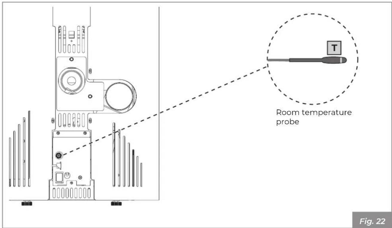
text_image
Room temperature probe Fig. 22
Configuration 1 is the default configuration for this appliance. In this case it is not necessary to make any changes.
The appliance leaves the factory with the room probe positioned on the rear panel (Fig. 22).
It is possible to place the room probe in another place to detect the desired room temperature.
Set configuration 1 to switch the appliance on and off either manually or according to a program.
The appliance modulates the power according to the room temperature read by the room probe placed on the stove itself.

You can set the "Eco-mode" function to have the appliance switch off or on again according to the room temperature set.
The antifreeze function can also be set in this configuration.

It is important to check that the appliance is set to Configuration 1.
This configuration can also be used to switch the appliance on and off manually or in a programmed way (with the Timer function active).
9 FIRST IGNITION
9.2 First start up
9.1 Pellet loading
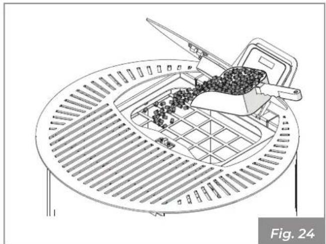
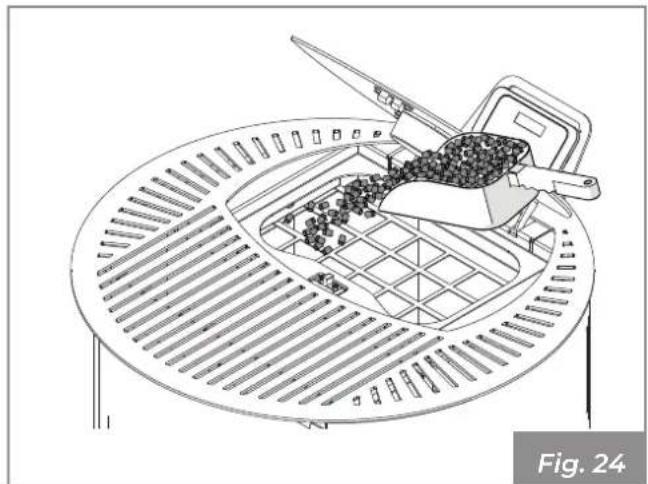
- Open the pellet loading hatch.
Connect the appliance to the mains, operate the power switch on the back of the appliance by turning it to "I".
If the connection is correct, the appliance emits a series of intermittent noises and the display lights up.
- Load the pellets.
See the display manual.
- Close the hatch.
10 MAINTENANCE
Cleaning can be carried out by the user.
Maintenance operations must be performed by an authorised technical assistance centre.
Before performing any maintenance operation, take the following precautions:
- Ensure that all appliance parts are cold.
- Make sure that the ashes are completely extinguished.
- Use personal protective equipment provided for by Directive 89/391/EEC.
- Make sure that the general line switch is turned off.
- Make sure that the power supply cannot be accidentally reactivated. Remove the plug from the wall socket.
• Always use appropriate equipment for maintenance. - Once maintenance or repair operations have been completed, before putting the appliance back into service, reinstall all the safety guards and reactivate all the safety devices.
10.1 Maintenance of the smoke system
To be carried out at least once a year, or every 4000 kg of pellets burned.
If there are horizontal sections, it is necessary to check and remove any deposits of ash and soot before they obstruct the passage of fumes.
In the event of failure to clean or inadequate cleaning the appliance may have operating problems including:
- bad combustion;
- blackening of the glass;
- blockage of the burn pot with accumulation of ash and pellets;
- deposit of ash and excessive deposits on the exchanger with consequent poor performance.
10.2 Appliance maintenance
To be carried out at least once a year, or every time the appliance signals maintenance request.
During the maintenance operation, the technician must:
- clean the flue gas transit area thoroughly and completely;
- check the condition and tightness of all the seals;
- check the condition of all internal components and make sure they are clean;
- make sure the flue gas outlet connection is sealed and clean;
- remove any deposits of pellet residues in the tank;
- check that there are no pellets or pellet residues in the appliance installation space;
- check the correct operation of the appliance;
- reset any warnings or alarms.
10.3 Ordinary maintenance cleaning program
10.3.1 Ordinary cleaning (User)
| EVERY TIME THE APPLIANCE IS TURNED ON | EVERY WEEK | |
| Burn pot (Fig. 26) X | ||
| Ash drawer/compartment (Fig. 27) X | ||
| Glass (Fig. 28) X | ||
| Fan grille X |
10.3.2 Ordinary maintenance (certified technical service centre)
| 1 YEAR (*) | |
| Door and burn pot seals X | |
| Smoke collector (Fig. 29) X | |
| Door safety (Fig. 30) X | |
| Flue gas system ("10.5.3 Maintenance of the smoke system" on page 64) | X |
| Device ("10.5.4 Appliance maintenance" on page 65) X |
(*) At least once a year or every 4000 kg of pellets burned.
10.4 Ordinary cleaning
10.4.1 Cleaning the inside of the firebox
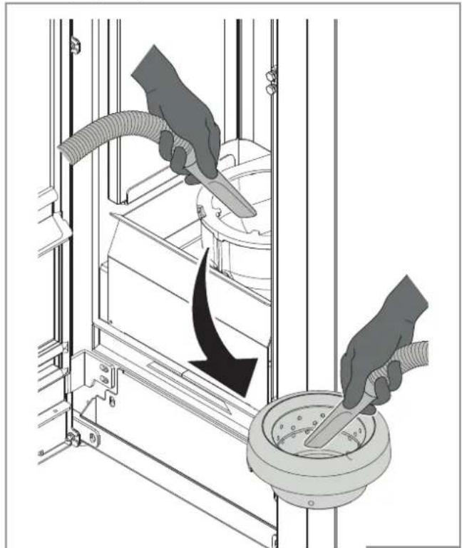
Daily or before each ignition, it is necessary to check that the burn pot is clean to ensure the free flow of combustion air from the holes of the burn pot itself.
Vacuum the ash accumulated in the burn pot (Fig. 26).

Remove the ash from the combustion chamber as the salts present cause corrosion of the metal. In addition, the ash could block the passage of air, varying the development of the flame which, if it approaches the glass, would increase corrosion.
After cleaning the burn pot, remove it from its housing and clean the space where it is contained (Fig. 26).
natural_image
Illustration of hands using a tool to clean or install a mechanical component, with no visible text or symbols.The image is purely indicative
Fig. 26
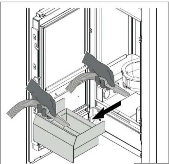
If necessary, remove the ash drawer and empty it, making sure to remove any residue in the compartment where it is contained (Fig. 27).

Using an ash vacuum can simplify the cleaning operations
natural_image
Technical illustration of hands installing or maintaining a flexible hose component inside a mechanical assembly (no text or symbols)The image is purely indicative
Fig. 27
10.4.2 Cleaning the glass
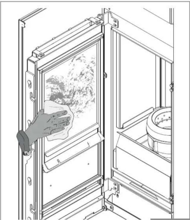
This is done with a damp cloth or damp paper towel passed through the ash (Fig. 28).
Rub until the glass is clean.
Do not clean the glass while the stove is on and do not use abrasive sponges.

Do not use solvents, acids or detergents, liquid detergents or aggressive products.
natural_image
Technical line drawing of a door with a hand cleaning a window, showing material and components (no text or symbols)The image is purely indicative
Fig. 28
10.5 Ordinary maintenance
10.5.1 Maintenance of flue manifold
After cleaning the burn pot, remove it from its housing and clean the space where it is contained.
Remove the ash drawer and, using a special ash vacuum, remove any residues in the compartment that contains it. Use a flexible brush to clean the exchanger pipes in the combustion chamber (Fig. 29).
Remove any residues that fall in the flue manifold using an ash vacuum.

natural_image
Technical line drawing of an internal mechanical device with visible wiring and components, no text or symbols present.10.5.2 Door safety
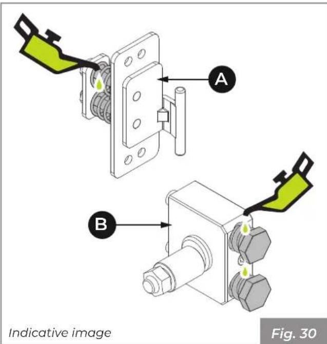
In order to guarantee the correct and safe operation of the fire box door, it is necessary to lubricate the springs of the closing mechanism, which may be located at the hinges (A) or at the door closing latch (B).
text_image
A B Indicative image Fig. 3010.5.3 Maintenance of the smoke system
If there are horizontal sections, it is necessary to check and remove any deposits of ash and soot before they obstruct the passage of fumes.
The incrustations inside the flue affect the optimum forced draught. When they reach a thickness of 5-6 mm, with high temperatures and sparks, they can ignite with easily imaginable consequences both for the flue and for the house.
In the event of failure to clean or inadequate cleaning the appliance may have operating problems including:
- bad combustion;
- blackening of the glass;
- blockage of the burn pot with accumulation of ash and pellets;
- deposit of ash and excessive deposits on the exchanger with consequent poor performance.
10.5.4 Appliance maintenance
To be carried out at least once a year, or every time the appliance signals maintenance request.
During the maintenance operation, the technician must:
- clean the flue gas transit area thoroughly and completely;
- check the condition and tightness of all the seals;
- check the condition of all internal components and make sure they are clean;
- make sure the flue gas outlet connection is sealed and clean;
- remove any deposits of pellet residues in the tank;
- check that there are no pellets or pellet residues in the appliance installation space;
- check the correct operation of the appliance;
- reset any warnings or alarms.
11 DEMOLITION AND DISPOSAL
The demolition and disposal of the appliance are the sole liability and responsibility of the owner who must act in compliance with the laws in force in their country regarding safety, respect and protection of the environment.
Disposal can be entrusted to a third party, provided only companies authorised for the recovery and elimination of the materials in question are used.

Always follow the regulations in force in the Country where the appliance is in operation for the disposal of materials and possibly for the disposal notification.

All disassembly operations for demolition must take place with the appliance stopped and without the power supply.
- Remove all the electrical equipment.
- Separate the accumulators in the electronics boards.
- Scrap the structure of the appliance using authorised companies.

Leaving the appliance in accessible areas is a serious danger to people and animals.
The differentiated disposal of the product makes it possible to avoid potentially negative consequences on the environment and health, and also allows recycling of the materials making up the product in order to achieve significant energy and resource savings.
Any liability for damage to people and animals always falls on the owner. Upon demolition, the EC marking, this manual and other documents relating to this appliance must be destroyed.
The crossed-out wheelie bin symbol that appears on the label of the appliance indicates that, at the end of its useful life, the product must be disposed of separately from other waste.
Pursuant to art.13 of Italian Legislative Decree no. 151 of 25 July 2005 implementing the Directive 2002/96/EC of 23 February 2003 on Waste Electrical and Electronic Equipment relating to the measures and procedures designed to prevent the production of waste electrical and electronic equipment, called WEEE, promoting the reuse, recycling and other forms of recovery so as to reduce the quantity to be disposed of and improving the intervention of the parties involved in the life cycle of such products.
natural_image
Simple line drawing of a trash bin with crossed lines indicating no waste or restriction (no text or symbols)
INHALTSVERZEICHNIS

4 DAS PRODUKT KENNEN 77
natural_image
Pile of cylindrical brown granules or pellets, no text or symbols visible4 DAS PRODUKT KENNEN
4.1 Beschreibung
MELITA
text_image
Technical diagram of a device with numbered components for identificationNINA
text_image
Technical diagram of a device with numbered components for identificationAbb. 3
text_image
Diagram of a server rack with numbered components for identificationAbb. 4
natural_image
Technical line drawing of a vertical cabinet or enclosure with height dimension labeled 113159 (no text or symbols beyond the label)
natural_image
Pure architectural floor plan lines without any text, numbers, or symbols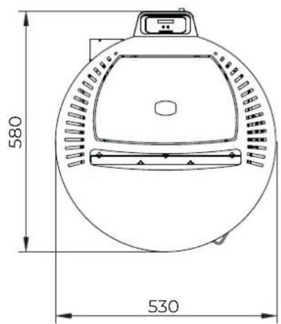
text_image
580 530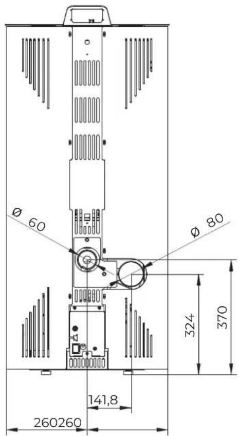
text_image
Ø 60 Ø 80 324 370 141,8 260260natural_image
Pure architectural floor plan lines without any text, numbers, or symbols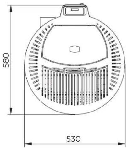
text_image
580 530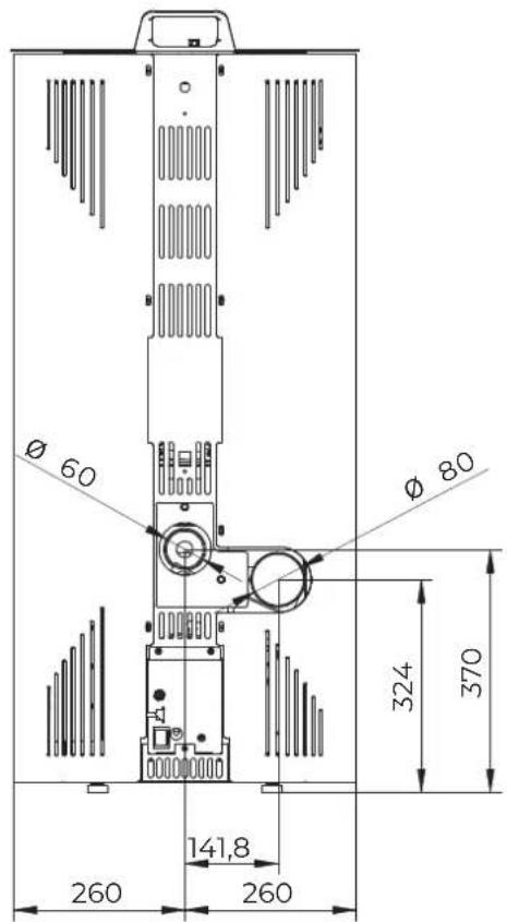
text_image
Ø 60 Ø 80 324 370 141,8 260 260natural_image
Technical illustration of a cylindrical industrial device with internal components and directional arrows, showing assembly steps (no text or symbols)5.1 Transport

6.3 Installationsort
natural_image
Technical line drawing of a pipe fitting with a coiled cable (no text or symbols)natural_image
Hand holding a device near a wall-mounted screen, with no visible text or symbols
natural_image
Diagram of a kitchen appliance with a cutting tool inserted, showing internal grid structure and ventilation slots (no text or symbols)natural_image
Diagram of a food preparation setup with a griddle, basket, and tool (no text or symbols)natural_image
Technical line drawing of a mechanical device with internal components and airflow indicators (no text or symbols)natural_image
Symbol of a trash bin crossed out by two diagonal lines (no text or numbers present)
INDEX

5 MANUTENTION ET TRANSPORT 115
5.1 Transport 115
6 PRÉPARATION DU LIEU D'INSTALLATION 116
natural_image
Technical line drawing of a server rack with labeled component A, showing internal structure and mounting points (no text or symbols beyond label)natural_image
Pile of cylindrical wooden sticks, labeled as Fig. 2 (no text on sticks)text_image
Technical diagram of a device with numbered components for identificationNINA
text_image
Technical diagram of a mechanical device with numbered components for identificationFig. 3
text_image
Diagram of a server rack with numbered components for identificationFig. 4
natural_image
Technical line drawing of a vertical cylindrical device with internal components and a top-mounted unit, showing dimension lines (no text or symbols)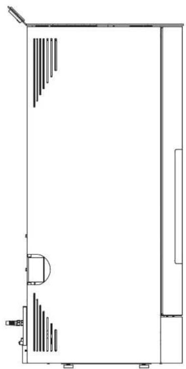
natural_image
Pure architectural floor plan lines without any text, numbers, or symbols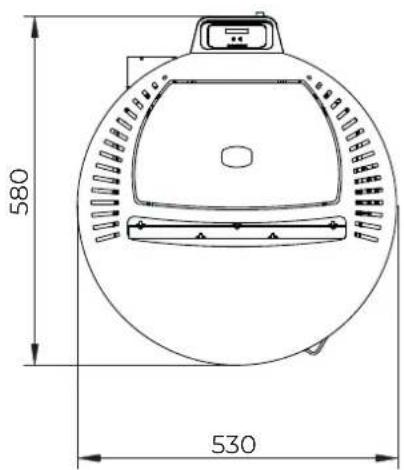
text_image
580 530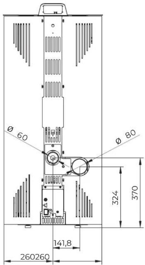
text_image
Ø 60 Ø 80 324 370 141,8 260260natural_image
Technical line drawing of a vertical cylindrical device with internal components and a top-mounted unit (no text or symbols)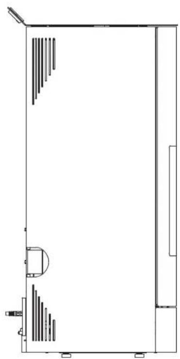
natural_image
Pure architectural floor plan lines without any text, numbers, or symbols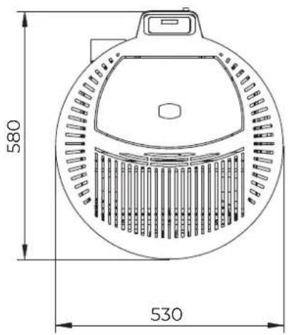
text_image
580 530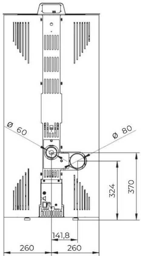
text_image
Ø 60 Ø 80 324 370 141,8 260 2605 MANUTENTION ET TRANSPORT
natural_image
Technical illustration of a cylindrical industrial device with internal components and directional arrows, no text or symbols present.5.1 Transport

natural_image
Technical diagram of a cylindrical device mounted on a base plate, with a 10 mm height dimension indicated (no text or symbols beyond labels)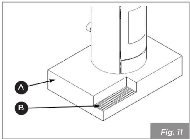
text_image
A B Fig. 116 PRÉPARATION DU LIEU D'INSTALLATION
natural_image
Technical line drawing of a pipe fitting with a coiled cable, labeled Fig. 17 (no text or symbols on the diagram itself)natural_image
Hand holding a device near a wall-mounted screen, with no visible text or symbols
natural_image
Diagram of a kitchen appliance with a gridded sink and a knife inserted, showing a black arrow indicating rotation (no text or symbols)natural_image
Diagram of a food preparation setup with a tray, griddle, and bowl containing granular material (no text or symbols)- Refermer la porte.

natural_image
Technical line drawing of an internal mechanical device with visible components and airflow path (no text or symbols)natural_image
Symbol of a trash bin crossed with a diagonal line and a horizontal bar below (no text or labels)ÍNDICE

2017/2102/UE: Directiva RoHS
2014/53/UE: Directiva RED (Radio Equipment Directive)
REGLAMENTO (UE) N. 305/2011 (CPR)
REGLAMENTO (UE) 2015/1185 (ECODESIGN)
natural_image
Diagram of a cylindrical device with labeled component A, showing internal structure and mounting points (no text or symbols beyond label)natural_image
Pile of cylindrical wooden sticks, labeled as Fig. 2 (no text on sticks)4 CONOCER EL PRODUCTO
4.1 Descripción
MELITA
text_image
Technical diagram of a device with numbered components for identificationNINA
text_image
Technical diagram of a device with numbered components for identificationFig. 3
text_image
Diagram of a server rack with numbered components for identificationFig. 4
natural_image
Technical line drawing of a vertical cylindrical device with internal components and a top-mounted unit, showing height dimension 113159 (no text or symbols beyond measurement label)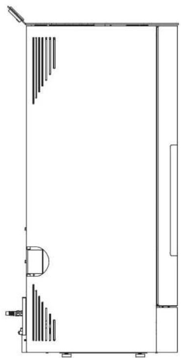
natural_image
Pure architectural floor plan lines without any text, numbers, or symbols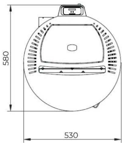
text_image
580 530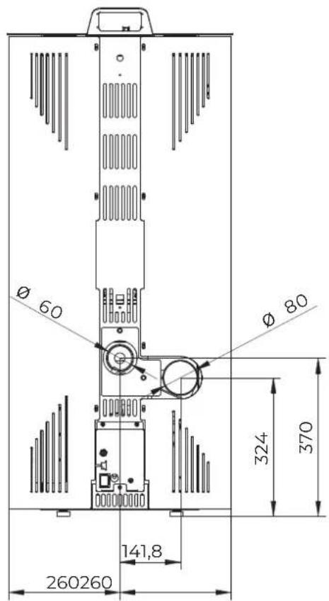
text_image
Ø 60 Ø 80 324 370 141,8 260260∅ 60 entrada aire comburente
∅ 80 salida humos
Dimensiones en mm
Fig. 5
NINA
natural_image
Technical line drawing of a vertical cylindrical device with internal components and a top-mounted unit (no text or symbols)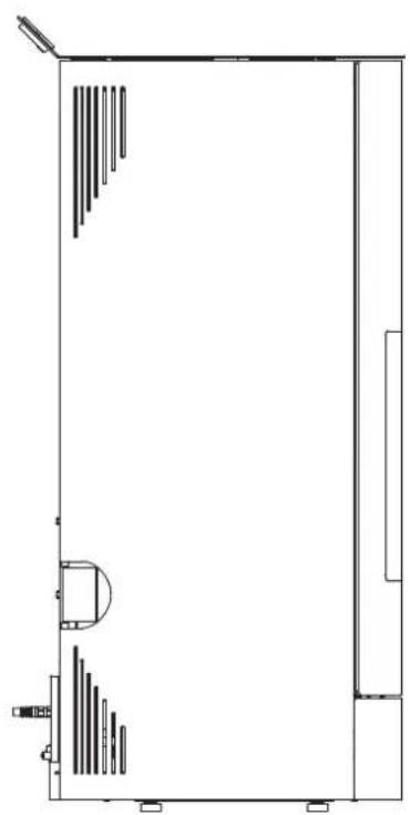
natural_image
Pure architectural floor plan lines without any text, numbers, or symbols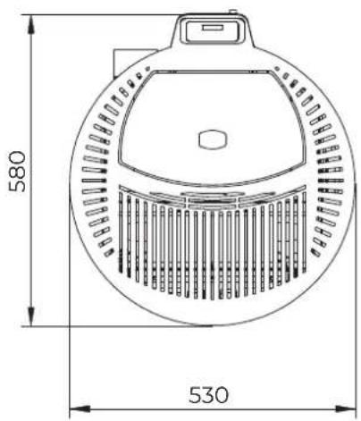
text_image
580 530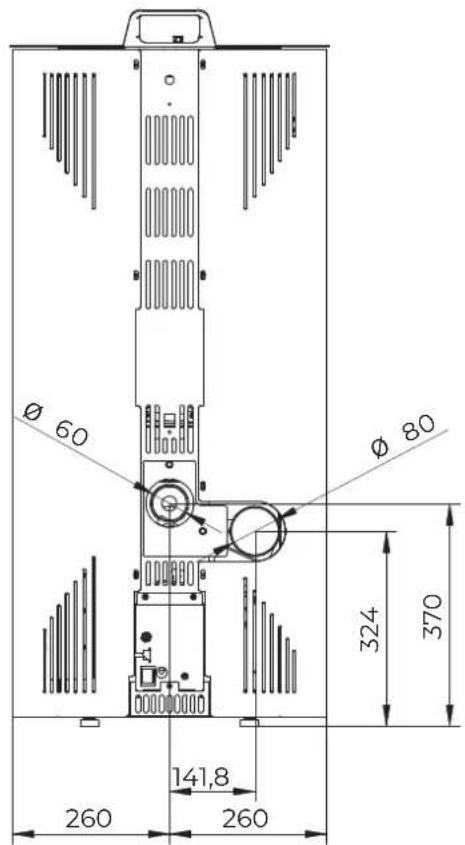
text_image
Ø 60 Ø 80 324 370 141,8 260 260∅ 60 entrada aire comburente
∅ 80 salida humos
Dimensiones en mm
Fig. 6
natural_image
Technical illustration of a cylindrical device with internal components and directional arrows, showing assembly or maintenance (no text or symbols)5.1 Transporte

natural_image
Technical diagram of a cylindrical device mounted on a base plate, with dimension annotation (10 mm) and labeled point A, no readable text or symbols beyond labels.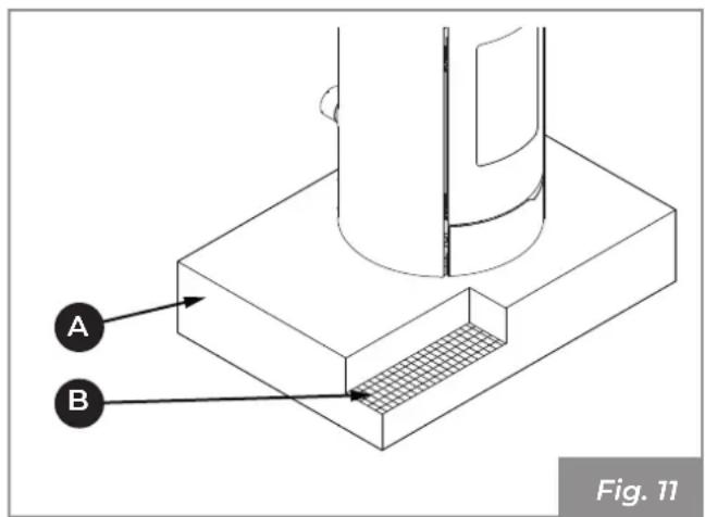
text_image
A B Fig. 11Pi = Pared inflamable
natural_image
Technical illustration of a pipe fitting with a coiled cable, labeled Fig. 17 (no text or symbols on the diagram itself)natural_image
Diagram of a hand holding a device near a wall-mounted screen, with no visible text or symbols
natural_image
Diagram of a kitchen appliance with a cutting tool inserted into a gridded tray (no text or symbols)- Cargar los pellets.
natural_image
Diagram of a food preparation setup with a griddle, basket, and knife (no text or symbols)- Cerrar la puerta.

natural_image
Illustration of hands using a tool to clean or install a mechanical component, with no visible text or symbols.natural_image
Technical illustration of hands installing or maintaining a flexible hose component inside a technical enclosure (no text or symbols visible)natural_image
Technical line drawing of a door with a hand cleaning a window, showing internal components and no text or symbols.natural_image
Technical line drawing of an industrial machine interior with visible wiring and components (no text or symbols)natural_image
Symbol of a trash bin crossed with a diagonal line and a horizontal bar below (no text or labels)PALAZZETTI
IL CALORE CHE PIACE ALLA NATURA
Palazzetti Lelio s.p.a.
Via Roveredo, 103
cap 33080 - Porcia (PN) - ITALY
Internet: www.palazzetti.it
Palazzetti reserves the right to change its products at any time and without notice in order to improve them without compromising their essential characteristics.