
MS755 - Pump Maruyama - Free user manual and instructions
Find the device manual for free MS755 Maruyama in PDF.

| Product Type | Piston pump (self-propelled sprayer) |
| Brand | Maruyama |
| Model | MS755 |
| Dimensions (L × W × H) | 551 × 312 × 417 mm |
| Weight (dry) | 20 kg |
| Rated speed (max) | 950 min⁻¹ |
| Water inlet flow rate (max) | 67 L/min |
| Maximum pressure | 5.0 MPa |
| Specified power (max) | 6.7 kW |
| Lubricant | SAE 10W-30 or SAE 30 non-detergent |
| Lubricant volume | 1.15 L |
| V-belt pulley | 229 mm (B-2) |
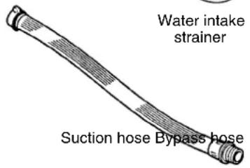
| Water inlet hose | 25 × 3.6 m (diameter × length) |
| Bypass hose | 19 × 3.6 m (diameter × length) |
| Water inlet strainer | 30 mesh |
| Cylinder material | MAC ceramic (long-lasting treatment) |
| Piston packing | Chemical-resistant rubber |
| Main uses | Spraying agrochemicals, herbicides, watering, cleaning |
| Safety precautions | Wear protective equipment, avoid flammable products, follow chemical manufacturer's instructions |
| Regular maintenance | Drain every 100 h (first at 50 h), check seals and hoses |
| Warranty | Does not cover modifications or unspecified uses |
Frequently Asked Questions - MS755 Maruyama
User questions about MS755 Maruyama
0 question about this device. Answer the ones you know or ask your own.
Ask a new question about this device
Download the instructions for your Pump in PDF format for free! Find your manual MS755 - Maruyama and take your electronic device back in hand. On this page are published all the documents necessary for the use of your device. MS755 by Maruyama.
USER MANUAL MS755 Maruyama
natural_image
Technical line drawing of a mechanical pump assembly (no text or symbols)Instruction Manual Manual de instrucciones Mode d'emploi
Thank you very much for buying this product.
This instruction manual describes how to use and maintain this product correctly.
Before getting started, please read this instruction manual carefully for a full understanding of the product.
Utilize this manual so that this product can function at its best performance longer.
After you read this manual, be sure to keep it at hand to carefully to check for any matter that you do not understand. Please note that the product may be partially different from the contents of the manual because we are always trying to offer better products.
If you have please contact your MARUYAMA Service dealer.
- Keep the instruction manual at hand.
- If you lose this manual, please obtain a replacement from MARUYAMA Service dealer.
- Do not modify this product, because doing so may create unsafe conditions which may be harmful or dangerous.
Purpose of use
This product is intended for the application of properly mixed agricultural and pest control chemicals. Please note that we are not liable for any accident caused by the use deviating from the range of the use purpose or any accident resulting from modification or disassembly without permission.
Precautions
This manual denotes handling precautions that are critical as described below.

DANGER
Personal death or serious injury will result if the warning is not followed.

WARNING
Personal death or serious injury may result if the warning is not followed.

CAUTION
Personal injury may result if the warning is not followed.
CAUTION
Machine damages may result if the warning is not followed.
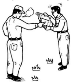
When letting another person run this product
Tell him/her how to run this product in advance and explain each warning label with [!] (Safety precaution mark) attached to the machine. To avoid any misunderstanding, tell him/her to read the instruction manual and precautions on safe work carefully and learn the handling method while checking the machine before getting started.
Particularly, explain the prohibited matters in detail.
As if you were using it!
natural_image
Two workers in uniform exchanging a large object, with grass falling below (no text or symbols)1. For Safe Operation 2
Precautions Before Getting Started 2
Precautions on Use (Chemical) 4
(Preparation for Operation) 5
(During Operation) 6
Precautions on Setup....7
Precautions on Setup/Post-use Precautions 9
2. Part Names and Operating Parts 10
Part Names....10
Checking Standard Accessories, Functions of Standard Accessories and
Operating Parts, and Warning Labels ⚠⋯11
3. How to Handle and Operate ....12
Preparation and Check – Spraying....12
Preparation and Check – Spraying – Stop 13
4. Cleaning, Maintenance, and Storage 15
Cleaning, Maintenance, and Storage 16
Troubleshooting and Actions for Power Sprayer 17
5. Servicing 19
After-sales Servicing 19
Changing the Direction of the Bypass Port 19
Machine Modification 19
6. Specifications 20
Table of Specifications 20
1. For Safe Operation
Precautions Before Getting Started
Before getting started, be sure to check and read the precautions on labels attached to the machine to learn the safe and correct handling method.
Precautions on Safety
Described here are just some examples. Do not forget that the operation is always accompanied by danger, to avoid any potential injury or harm.
These people are prohibited from spraying:
• People who are unable to perform normal operation due to fatigue, illness, effects of drugs, etc.
• People under the influence of alcohol
- Pregnant women
• Injured people and those who are easily affected by agrichemicals
• Young people (below 15 of age)
• People not familiar with the proper use of this product
Wear the clothes suitable for operation.
The operator must wear the clothes fitting his/her body.
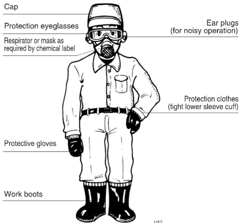
WARNING
Check, maintain, all safety equipment so that they will function as intended.
Just In Case
Handling of Agrichemicals
WARNING
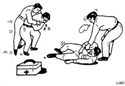
Consult the chemical manufacturer's label and MSDS for all required safety equipment, application instructions, first aid instructions and other precautions and safety warnings. Follow all chemical manufacturer's label and MSDS instruction. If you have any questions, contact the chemical manufacturer for advise prior to use of chemicals.
If you do not know the first-aid action!
natural_image
Illustration of two individuals performing CPR on a patient lying on the ground, with a first aid kit nearby (no text or symbols)Check the method of emergency call.
Handling of Chemical
WARNING
(1) Read the instruction manual of the chemicals carefully. Read the labels for the chemicals and fertilizer to be used carefully to become familiar with how to use them and precautions on use.
(2) Wear the clothes that prevent exposure to the conditioner.
(3) Prepare the necessary volume of conditioner.
(4) Prepare and place the conditioner at the spraying location. Check the direction of wind and spray at the location so environmental contamination will not occur.
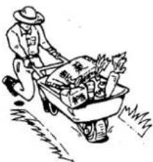
(5) Do not prepare on the machine or in the tank in advance of transportation. The spilt conditioner may result in environmental contamination.
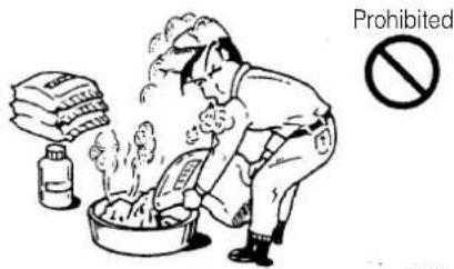
(6) Do not store or transport the conditioner along with any drink or food. When transporting, be careful not to break the container.
(7) Make a spraying plan. Prepare the conditioner not to leave any remainder.
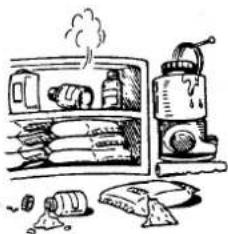
(8) Put the remaining conditioner in a fully closed container or bag that lets anyone identify the content. Isolate from any other materials and store the container or bag so that any unauthorized person cannot take it. Never store the conditioner in a container for drinks or food.
(9) Dispose the empty bag, can, and bottle according to the instruction manual of the conditioner or to the instruction by the local government.
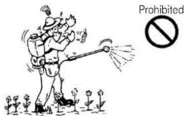
DANGER
- Do not hold the spraying hose. You may be exposed to agrichemicals. Because of the loose nozzle head.
WARNING
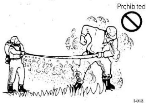
- Do not use any highly combustible agrichemical because fire or combustion may occur.
CAUTION
- If the volume sprayed per unit area or the type of conditioner is incorrect, hazardous spills may be caused.
- Do not leave the conditioner in the conditioner tank for a long time because this may affect the machine.
Perform the operation in a timely manner.
(1) Check the direction of wind and the situation surrounding the field. If wind is strong, the conditioner may drift into undesired areas. Therefore, please avoid the operation.
(2) Avoid the high-temperature times of day.
(3) Do not perform the operation if you are tired or sick.
(4) Do not enter the field immediately after spraying.
Be sure to read the manual!
1-008
Wear proper clothes.
1-009
Do not put the chemical(s) together with food.
natural_image
Cartoon illustration of a person pushing a wheelbarrow loaded with vegetables and grass (no text or symbols)Prohibited

1-010
Separate and store the chemical(s) in good order.
natural_image
Illustration of a kitchen appliance with a steaming refrigerator, a washing machine, and scattered food items (no text or symbols)Prohibited

1-011
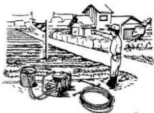
Check the direction of wind and surrounding area.
natural_image
Illustration of a person standing near industrial equipment and a flag, with houses in the background (no text or symbols)1-020
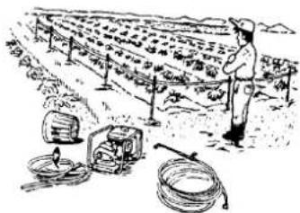
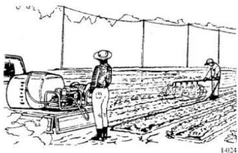
Do not enter immediately after spraying.
natural_image
Illustration of a person standing in a farm with irrigation equipment and a water pump (no text or symbols)1-021
Precautions on Use (Inspection, Maintenance and transportation)
(1) When transporting sprayer on a truck, take the proper action so that the machine will not fall.
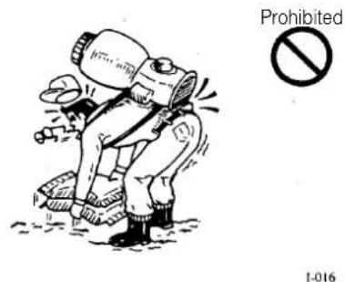
(2) When loading/unloading a heavy material, do not take an unreasonable stance nor perform one-man operation.
(3) Refill the fuel after the engine cools down. Do not smoke while refueling. Avoid static discharge when refueling. Tighten the lid on the fuel tank snualy. Remove any spilled fuel completely.
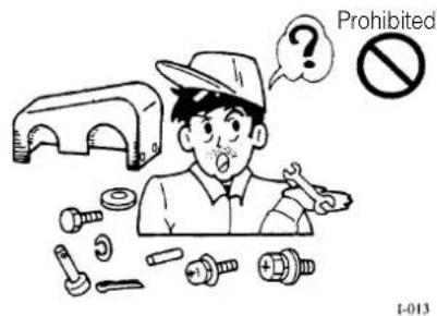
(4) Check for loosened bolts/nuts on each part and slipped-away or damaged setting pins.
(5) After covers for rotary parts, etc. are removed for maintenance, etc., re-attach all of them correctly.
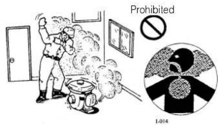
(6) Do not start the engine near combustible materials or at a poorly ventilated or narrow location. Do not operate indoors.
(7) For electrical wiring, oils, water, and fire are strictly prohibited.
Fire prohibited

Attach the safety cover accurately!
Be careful of ventilation and combustibles!
Points in Operation
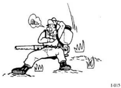
(1) Avoid fatigue by taking proper breaks.
(2) Always keep in mind that the working machine containing the conditioner is a heavy material.
(3) Pay attention to the clothes, field conditions, and direction of wind to avoid exposure to agrichemicals and environmental contamination. The direction in which agrichemicals flow may be dangerous.
(4) For cooperative operation, define and check accurate signs among all members.
(5) Refuel without letting fuel spill out after the engine is stopped and cooled down.
(6) During operation, do not allow any unauthorized person to come into the work area being sprayed.
(7) Depending of the agent to be sprayed, static electricity can be avoided by using a ball chain (optional).
(8) Check the packing and tighten the lid on the chemical tank so that the chemical will not come out.
(9) Do not direct the spray nozzle toward any person.
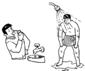
(10) Before any break, rinse your mouth out and wash your hands and face with soap and water.
(11) If you feel ill while or during spraying, treatment by a medical doctor is immediately needed. Seek medical attention immediately.
Have a rest properly.
natural_image
Cartoon illustration of a firefighter running with a baton, no text or symbols presentUnreasonable work prohibited!
Pay attention to the field and environment!

Determine signs for cooperative work!
natural_image
Illustration of two workers operating machinery in a field, no text or symbols presentPoints in Handling This Machine
Applications
○Spraying chemicals for crops from the fields of rice, crops from general vegetable fields, fruit trees, mulberry, and trees
○Spraying pesticide solutions or insecticides for cattle houses, chicken houses, and city sanitation
○Spraying liquid herbicides ○Spraying water to crops from general vegetable fields or fields of rice
○Washing cattle houses, chicken houses, agricultural crops, and agricultural instruments
○Washing wall surfaces, etc. of building structures and protecting electric feeder lines from salt damages

CAUTION
Do not use strong acid, strong alkali, chemical solvents, or hot water. This may cause damage to your sprayer or spray pump.

WARNING
- When setting up this product with a motor, please contact your MARUYAMA service dealer.
- When driving this product using a V pulley or V belt, be sure to attach a cover over the rotary part so that it cannot be easily touched during check.(Keep the cover being attached for operation and check. If the cover cannot be installed, special considerations are required e.g. be sure to provide a fence around the working machine.)
- Be sure to "stop" this machine before check or adjustment.

CAUTION
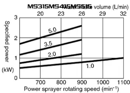
- Choose pulleys and engine speeds within the ranges of the specified rotating speed, pressure, and water volume.
If these ranges are exceeded during use, damages of the power sprayer or accidents may be caused. - The rated output of the motor must be at or above the specified power of the power sprayer. Otherwise, its performance be less than advertised.
- Be sure to set up in such a way that the oil gauge on the power sprayer can be easily checked.
CAUTION
- To fasten this machine use bolts with proper sizes and strength. Install the machine securely. If installation of the power sprayer or motor is unstable, vibration may occur and the power sprayer may be adversely affected.
- Select the proper-size V pulley or V belt complying with the specified power.
- Use the size of the V pulley shaft hole or key groove matching the shaft.
Do not use any shaky V pulley hole or key groove because accidents may be caused by detrimental vibration,
- The shaft end must slightly retract from the pulley surface. Tighten the bolt accurately via the washer. Use the V pulley set screw as necessary.
- Install the V pulley of the motor and the V pulley of the power sprayer on a straight line. If the V belt is not set straight when viewed down, an unreasonable force is applied and the V belt may be damaged or slip away.
- The V belt must not be too tight or too loose. If it is too tight, the engine or pump bearings may be damaged. If it is too loose, belt damages or slip-away may be caused.
- When using two or more V belts, use the same type and size.
- When replacing V belts, replace all at the same time.
Piping

DANGER
- Use the same pipe type and size for the hose and nozzle to be connected. When connecting, be sure to check the packings and connect accurately.
If the pipe size or type is inadequate, the packing is lost or damaged, or the threads is loose, you may be exposed to the chemical. Also, you may be exposed to the chemical because the packing comes out or is damaged if the fittings are over-tightened. Tighten the screw adequately. - Before preparing the conditioner, be sure to check for leaks with fresh water.
(Water intake)
- The standard suction tube diameter is the diameter of the pump suction port. If the suction hose has elbows or valves, etc., use one-pipe size larger suction tube diameter.
CAUTION
If the suction tube diameter is smaller than required, performance degradation or failures may be caused.
- Suction pump head must be 3 meters or less.
(Spraying)
- Select spraying hose rated at or above the pump pressure.
(Hose)
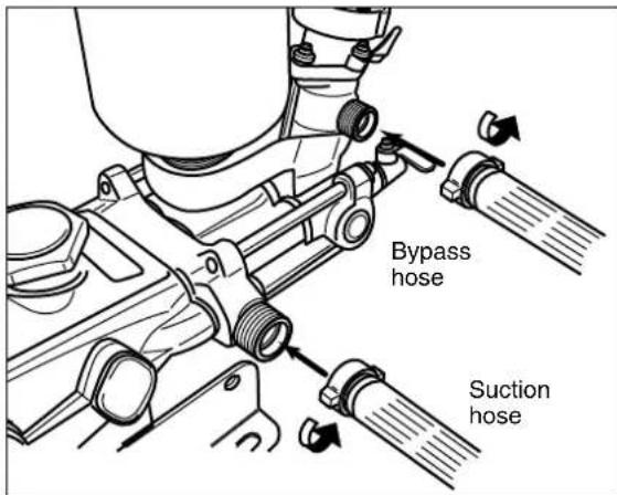
- Put the suction hose and bypass hose in the tank accurately and fasten them with clamps, etc. securely.
- When connecting the hose, be sure to check any seals and threads for tightness.

WARNING
Connect the bypass hose only to the bypass port. If the bypass port is fully closed by connecting a valve, the machine may be damaged and personal injury may occur. Therefore, never connect a valve to the bypass port or hose.
(Nozzle)
- Select a nozzle that flows approximately 30% of the bypass volume.

DANGER
- If proper nozzles (proper to performance of the pump), the standard fittings are removed, or the nozzle is handled unreasonably, the original performance cannot be exercised and troubles or, depending on the case, personal injury or damages may be caused.
CAUTION
- Do not point the nozzle toward people because exposure to the chemical may occur.
Points on Engine Operation

DANGER
- The fuel is combustible. Do not put fire close to the operating location.
- Be sure to stop and cool down the engine before fuel refilling. Wipe off the spilt fuel completely.
- When refilling fuel or performing maintenance, do not smoke or put lit items close to the machine.
- After this machine is refilled with fuel, separate the gas can used to refueling at least 3 meters then start the engine.
- Do not refill the fuel exceeding the standard volume, give strong vibration, nor tilt the machine.

WARNING
- The exhaust gas from the engine is harmful. Do not run the engine indoors because carbon monoxide poisoning may occur. Be careful not to inhale the engines exhaust gas.

CAUTION
- The engine is hot while it is running and immediately after it is stopped. Burn may occur if the muffler or cylinder fin is touched.
- A high voltage is delivered to the spark plug while the engine is running. Never touch the spark plug and plug cord because it is dangerous.
CAUTION
Strictly follow the above instructions and read the instruction manual of the engine carefully. Refer to any additional requirements described by your engine manufacturer.
Post-use Precautions
(1) Spray the applicable chemical or fertilizer so that it will not remain in the conditioner tank.
(2) Remove the conditioner from the machine completely. Rust generation or failures may occur.
(3) Remove the fuel before long term storage.
(4) Rinse your mouth out and wash your body immediately after spraying chemicals.
(5) Fully clean the protectors used for the operation and wash spraying chemicals.
(6) If any part is damaged, repair it before storage. In this case, use the genuine parts designated by MARUYAMA for parts and consumables.
(7) Store the machine at a dry location avoiding dust adhesion.
Clean after work!
natural_image
Illustration showing a person washing a faucet while another person swings in shower (no text or symbols)1-019
2. Part Names and Operating Parts
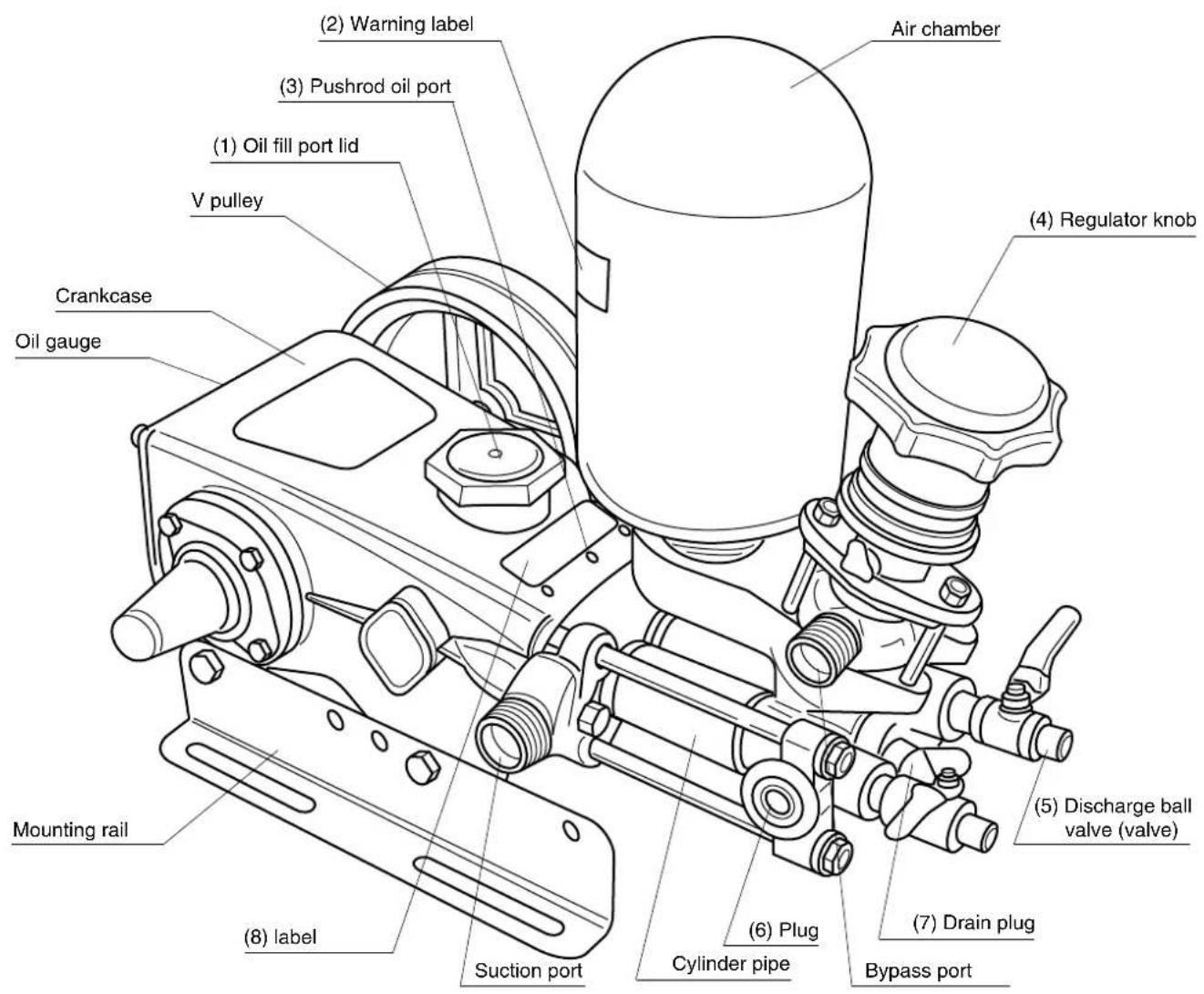
Part Names
Part Names
Checking Standard Accessories
After the package is opened, make sure that all accessories are provided first. If any accessory is missing or broken, please contact MARUYAMA service dealer immediately. Sizes and quantities of accessories are listed in the Table of Specifications on Page 20.
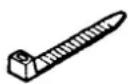
Standard Accessories

natural_image
Simple line drawing of an open book with a grid on the front page (no text or symbols)Instruction manual
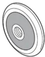
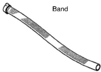
natural_image
Illustration of a curved, segmented object labeled 'Band' (no other text or symbols)Product Features
- Since the chemical solution always flows in one direction, the water intake mechanism is a reasonable one.
- The cylinder is durable because it is treated with the MAC process (ceramic).
- The piston packing uses a special rubber and it is resistant to chemicals.
Functions of Operating Parts/Warning Label
(1) Oil refill port lid:
Before starting operation, open this lid and be sure to refill the gasoline engine oil (SAE 10W-30 or equivalent).
(2) Warning label
• Always remove dirt and must so that contents will be clearly legible.
- If the warning label is damaged, replace is with a new one.
- If the part with a warning label is replaced, be sure to attach the label to the same position on the new label.
(3) Pushrod oil port:
Before starting, refill about 3 to 5 drops of oil (SAE 10W-30 or equivalent).
(4) Regulator knob:
Dial for pressure adjustment.
- Turning clockwise increases the pressure.
- Turning counterclockwise decreases the pressure.
(5) Discharge ball valve:
Used to connect the spraying hose. If the lever on the valve is turned by 90 degrees, the valve is "opened".
(6) Plug:
Remove this plug to use to supply water.
(7) Drain plug:
Loosen this plug to drain water. Water in the pump can be removed.
(8) Label:
Indicates the serial number.
3. How to Handle and Operate
Preparation and Check – Spraying

natural_image
Mechanical assembly diagram showing a tool interacting with a motor and a circular cross-section (no text or symbols)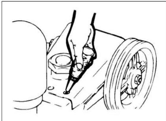
natural_image
Technical line drawing of a mechanical assembly with pulleys and a shaft (no text or symbols)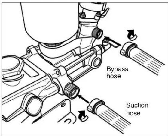
CAUTION
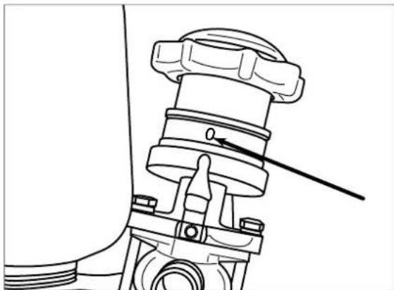
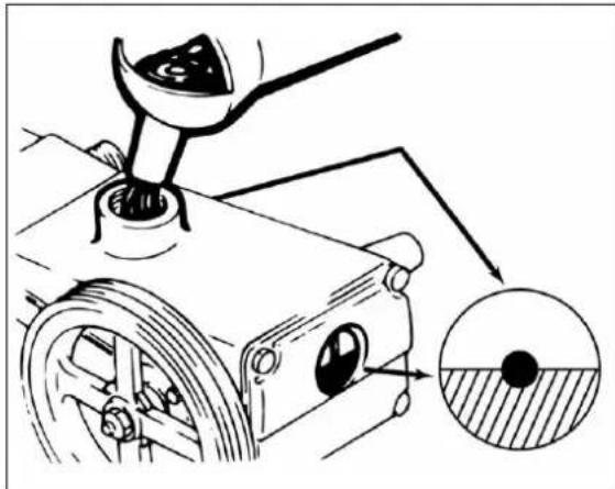
This power sprayer does not contain oil. Before use, be sure to supply oil.
- Fill with the oil (SAE 10W-30 or equivalent) to the red circle on the center of the pump rear oil gauge or to the red circle on the center of the pump side oil gauge.
- Refill about 3 to 5 drops of oil (SAE 10W-30 or equivalent) to three holes (oil refill port) on the front of the crankcase.

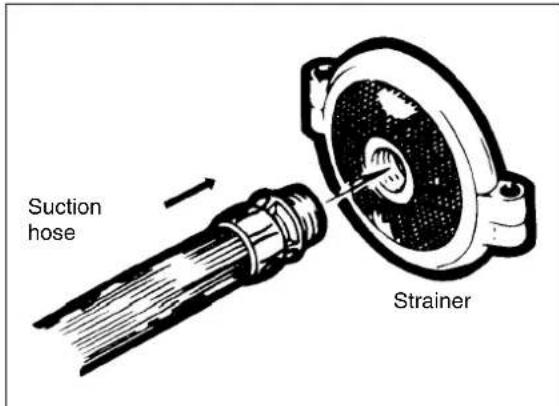
CAUTION
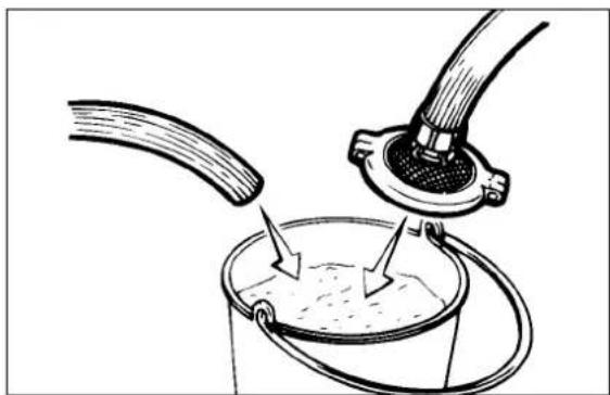
Before attaching the suction hose and bypass hose, check the packing. Particularly for the suction hose, vibration and insufficient water intake on this machine may be caused, resulting in the reduced pump life.
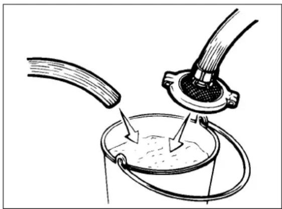
- Attach the strainer as a standard accessory. (If a non-standard part is being used, please contact MARUYAMA service dealer.)
natural_image
Illustration of a bucket being inserted into a container with a hose, showing fluid flow direction (no text or symbols)- When starting, perform test run with fresh water to make sure that the power sprayer is not faulty.

CAUTION
If the power sprayer is faulty, stop it immediately. See Troubleshooting and Actions for Power Sprayer on Pages 18 and 19.
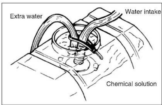
- When putting the hose in the chemical tank, set the water intake pump head within 3 meters.

CAUTION
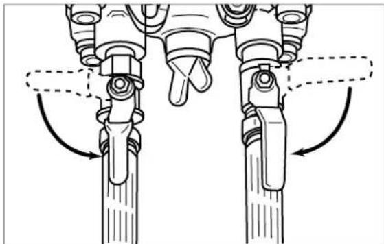
Moving of the water intake hose and extra water hose is dangerous, so fasten them with the attached band securely.
• Make sure that the strainer is securely in the water source.
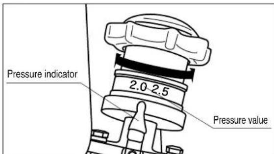
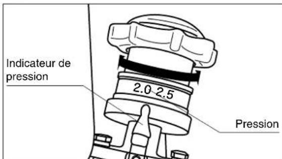
- As shown in the figure, move the pressure control valve handle up to the "Start" position.
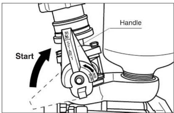
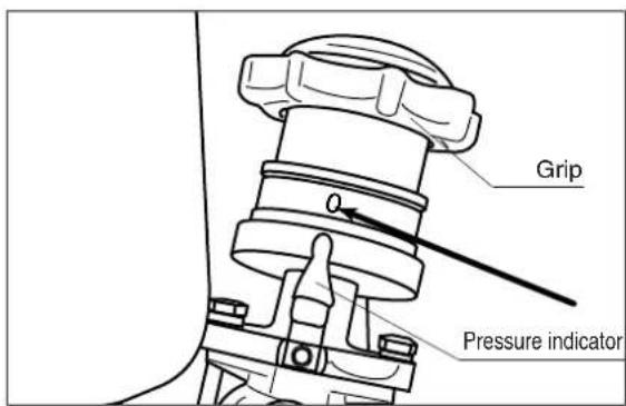
- Align the "0" scale on the grip with the pressure indicator position.
CAUTION
Note that starting in the pressurized state may damage the piston packing because water intake cannot be performed and idling occurs.
- Close the discharge ball valve.
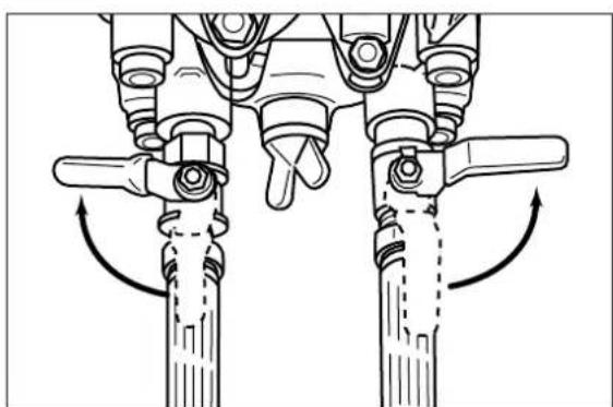
natural_image
Mechanical assembly diagram showing two vertical components with rotational arrows indicating motion (no text or symbols)
CAUTION
If water intake is started without the valve closed, the conditioner may suddenly come out of the valve or nozzle may move fast. Be sure to close the valve.
natural_image
Technical line drawing of a mechanical component with internal fan structure (no text or symbols)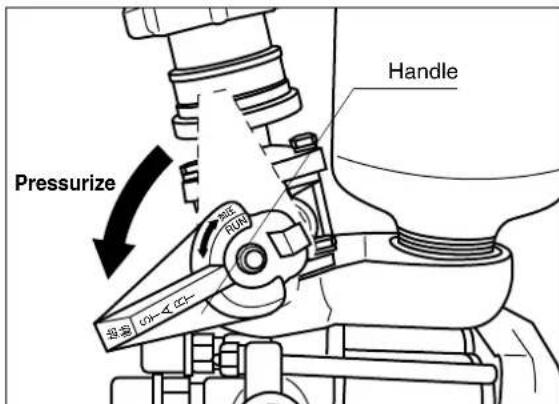
natural_image
Technical line drawing of mechanical components with no visible text or symbols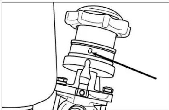
natural_image
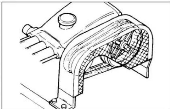
Technical line drawing of a mechanical assembly with no visible text or symbols- At the start and during operation, be sure to keep the belt cover attached.

WARNING
Since the rotary part may result in injury to personnel, be sure to attach the belt cover. If the belt cover cannot be attached, be sure to take special considerations e.g. provide a fence around the working machine.
- Rotate the pressure control valve handle to the "Pressurize" position.
CAUTION
- Rotate the pressure control valve handle fully. If the handle is in a midway and operation is started, the internal seat will be damaged.
- Make sure that water intake is in progress. If water intake is not performed (idling is kept) for at least one minute after the start, the piston packing will be damaged. Again, see Troubleshooting and Actions on Pages 17 and 18 and repeat the operation.

CAUTION
If the pressure is suddenly increased during two-person operation, a strong reaction force is given to the spray apparatus and it is dangerous. Open the valve after a sign is given in advance from spray operator.
Stop
- When stopping the pump, return the grip to "0", and the handle to the "Start" position. A compression spring is used for pressure adjustment. If a positive pressure remains in the hose, the pressurized liquid may come out when removing the pipe.
4. Cleaning, Maintenance, and Storage
natural_image
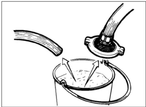
Diagram of a pipe being inserted into a bucket with a hose inserted, showing fluid flow direction (no text or labels)• After the operation, remove any fluid, drain the chemical solution remaining in the tank, then perform cleaning. Future problems with pump start can be prevented by normal regular cleaning.
CAUTION
For disposal of water after washing this machine, special care must be take so that chemical disasters will not occur same as the conditioner.
For the chemical handling method, read the instruction manual of the chemical carefully.
- Remove the nozzle from the hose, lift the water intake strainer from water, and run this machine at a low speed with the valve opened to drain water (Grip: "0", Handle: "Start").
natural_image
Diagram showing a pipe being inserted into a bucket with arrows indicating flow direction (no text or labels)CAUTION
Idling must be less than one minute for machine protection.
natural_image
Technical line drawing of a mechanical valve assembly with no visible text or symbols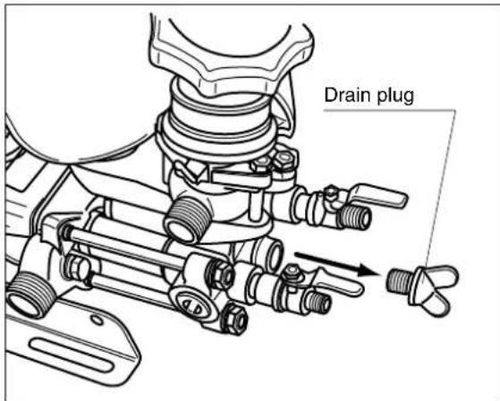

natural_image
Mechanical assembly diagram showing a lever pressing a component with a magnified inset showing a circular cross-section (no text or symbols)- If the water intake hose and extra water hose are left connected, the packing may be damaged and leaks may occur. Be sure to remove and store them.
- Store the regulator control spring with no load applied. To maintain the correct pressure indication, return the grip to "0", and the handle to the "Start" position.
- To prevent damages due to freezing in winter season, remove water completely before storage. Specifically, loosen the drain plug shown in the figure, drain water from the inside of the machine, and perform cleaning, maintenance, and storage.

CAUTION
Remove oil after oil cools down.
- Before replacing oil, make sure that this machine has stopped.
- For the first time replacement, replace oil after 50 hours have elapsed. Then, replace every 100 hours. Since oil degrades, replace oil at least once a year (SAE 10W-30 or equivalent) even if the 50 or 100 hours mark has not passed.
- “Troubleshooting and Actions for Power Sprayer” lists conditions that may occur and the actions to be taken. Should any failure occur, see the list and take the proper action. If you do not know the cause or have any question, please contact your MARUYAMA service dealer.
- Model
- Serial No.
- Failure description (what resulted in what how by doing what)
Detail these matters.
For Ⓞ, ask your MARUYAMA service dealer for adjustment or repair.

WARNING
Do not remove the cap on the top of the pressure control valve grip and adjust the screw. A pressure higher than specified may occur, the machine may be damaged, and personal injury may occur. Therefore, never take this action.
| State | Cause Action | |
| (1)No suctionor low suction | Transmission | Belt slip Adjust/replace______ |
| To the water intake port | Suction clogged with dust / dirt Clean______Suction hose damaged/bent Repair/replaceWater intake connection packing failure ____ Repair/replaceConnection error ____ Connect correctlyToo long water intake hose Replace______Too large water intake pump head–Decrease depth | |
| Water intake and pressurizing part (cylinder) | Water intake valve/discharge valve clogged with dust or stuck— CleanWater intake valve/discharge valve assembly error— Assemble correctlyWater intake valve/discharge valve damaged or worn out — Correct/replaceDischarge valve spring broken Replace______Piston packing damaged Replace______O-ring damaged Replace______Seal packing damaged Replace______ | |
| Pressure control | Pressure control valve handle in the pressurizing state — Move the handle to the start positionPressure control stuck in position—— Disassemble/clean | |
| (2)Pressure does not increase | Water intake and pressurizing part | Insufficient water intake volume See (1)— |
| Pressure control | Pressure control valve ball/ball seat damaged— ReplacePressure control valve rod error Adjust/replacePressure control valve spring cylinder error — Repair/replacePressure control valve spring damaged/degraded — Replace | |
| (3)Pressuredecreases ifthe dischargevalve isopened | Nozzle | Nozzle worn out Replace____Excessive nozzle spray volume____Replace with a proper nozzle |
| Power sprayer | Low water intake volume See (1)____ | |
| Hose | Too long spray hose ____ Set the proper lengthToo thin spray hose ____ Set the proper thicknessWater leak from hose connection Repair/replace | |
| (4) Spraying hose vibration | Air chamber filled with water ____ Open suction line to allow air in(idling within 1 minute)Poor pressure control valve motion ____ Disassemble/adjustWater intake/pressurizing line error ____ Disassemble/adjust(clogging, looseness)Nozzle clogged Clean____ | |
| (5) Noise | V pulley fastening bolt loosened Retighten/replaceConnection rod bolt, etc. loosened RetightenBearing broken Replace____Pressure control valve assembly error AdjustAir intake Check____ | |
| (6) Liquid leak/oil leak | O-ring damaged Replace____Seal packing damaged Replace____Oil seal damaged Replace____Tightening/assembly error ____ Disassemble/adjust | |
After-sale Servicing
- If any trouble is found during check at the start or during use, perform the proper maintenance immediately. Please contact your MARUYAMA Service dealer.
- Trouble description
○Model
○Serial No.
○Failure description
What resulted in what how by doing what.
Describe the details.
- To use this product safely, correct operation and periodic maintenance are required. Please request your MARUYAMA Service dealer for check and maintenance.
Changing the direction of the extra water port
- To change the direction of the bypass port, a new handle is required. Please contact MARUYAMA Service dealer.
- Do not attach any device or valve to the bypass port or hose. Pump damage will occur.
Machine Modification

WARNING
Do not modify the machine because it is dangerous. Machine modification or use not specified by the instruction manual may not be covered by the guarantee.
Table of Specifications
| Name | MS315 | MS415 | MS515 | MS615 | MS655 | MS755 | ||
| Basic dimensions (mm):Length x Width x Height | 415×242×298 | 415×242×361 | 449×271×359 | 510×312×397 | 510×312×417 | 551×312×417 | ||
| Mass (dry) (kg) | 10.5 | 11 | 14.5 | 19 | 19 | 20 | ||
| Performance Accessories | Rotating speed (mln-1) | Maximum | 900 | 1100 | 900 | 850 | 1000 | 950 |
| Water supply | 1100 | 1500 | 1200 | 1100 | 1200 | 1050 | ||
| Water intake volume (L/min) | Maximum | 26 | 32 | 37 | 47 | 56 | 67 | |
| Water supply | 32 | 41 | 50 | 61 | 63 | 73 | ||
| Pressure (MPa) | Maximum | 5.0 | 5.0 | 4.0 | 5.0 | 5.0 | 5.0 | |
| Water supply | 1.0 | 1.0 | 1.5 | 1.5 | 1.5 | 1.5 | ||
| Specified power (kW) | Maximum | 2.6 | 3.3 | 2.9 | 4.7 | 5.5 | 6.7 | |
| Water supply | 1.0 | 1.3 | 2.0 | 2.6 | 2.6 | 2.9 | ||
| Spray valve | G1/4 , G3/8 | G3/8×2 | ||||||
| Type of lubricant | SAE10W-30 or SAE30 Non-Detergent | |||||||
| Lubricant volume(L) | 0.6 1.15 | |||||||
| V pulley(mm) | 152 (A-2) | 178 (A-2) 229 (B-2) | ||||||
| Instruction manual | 1 | |||||||
| Water intake hose | 19×3m | 25×3.6m | ||||||
| Water intake strainer | 30 mesh | |||||||
| Extra water hose | 13×3m | 19×3.6m | ||||||
| Band | 350mm | |||||||
line
| Power sprayer rotating speed (min⁻¹) | MS315MS40MS615 volume (L/min) | Specified power (kW) | | ----------------------------------- | ------------------------------ | -------------------- | | 700 | 2.0 | 1.0 | | 800 | 2.5 | 1.2 | | 900 | 3.0 | 1.5 | | 1000 | 3.5 | 1.8 | | 1100 | 4.0 | 2.0 |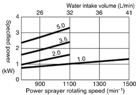
line
| Power sprayer rotating speed (min⁻¹) | Water intake volume (L/min) | Specified power (kW) | | ----------------------------------- | -------------------------- | -------------------- | | 900 | 26 | 1.0 | | 1100 | 32 | 1.5 | | 1300 | 36 | 2.0 | | 1500 | 41 | 3.5 |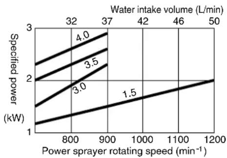
line
| Power sprayer rotating speed (min⁻¹) | Water intake volume (L/min) | Specified power (kW) | | ----------------------------------- | -------------------------- | -------------------- | | 800 | 4.0 | 2.0 | | 900 | 3.5 | 2.5 | | 1000 | 3.0 | 3.0 | | 1100 | 2.5 | 3.5 | | 1200 | 2.0 | 4.0 |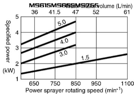
line
| Power sprayer rotating speed (min⁻¹) | Specified power (kW) | | ----------------------------------- | -------------------- | | 650 | 2.0 | | 750 | 3.0 | | 850 | 4.0 | | 950 | 5.0 | | 1100 | 6.0 |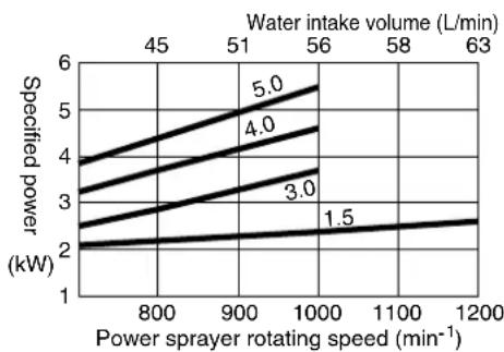
line
| Power sprayer rotating speed (min⁻¹) | Water intake volume (L/min) | Specified power (kW) | | ----------------------------------- | --------------------------- | -------------------- | | 800 | 45 | 2.0 | | 900 | 51 | 2.5 | | 1000 | 56 | 3.0 | | 1100 | 58 | 2.5 | | 1200 | 63 | 2.5 |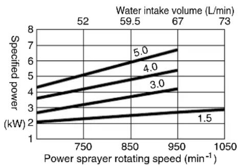
line
| Power sprayer rotating speed (min⁻¹) | Water intake volume (L/min) | Specified power (kW) | | ----------------------------------- | --------------------------- | -------------------- | | 750 | 52 | 4.0 | | 850 | 59.5 | 6.0 | | 950 | 67 | 7.0 | | 1050 | 73 | 7.0 |* The unit in the graph is MPa
natural_image
Two workers in uniform exchanging items, one standing and one kneeling, with crown symbols visible (no text or symbols present)natural_image
Illustration of two individuals performing CPR on a man lying on the ground, with a first aid kit nearby (no text or symbols)natural_image
Illustration of a person standing near a rural field with hoses and houses (no text or symbols)natural_image
Illustration of a person standing in a farm with water pumps and equipment (no text or symbols)1.021
natural_image
Cartoon illustration of a firefighter in action, shouting with a speech bubble (no text or symbols)natural_image
Illustration of two workers operating machinery in a field, no text or symbols presentnatural_image
Illustration showing a person drinking from a faucet while another person showered with a showerhead (no text or symbols)1-019
natural_image
Simple line drawing of an open book with a grid pattern on the cover (no text or symbols)natural_image
Simple line drawing of a curved, elongated object with no text or symbolsnatural_image
Mechanical assembly diagram showing a tool interacting with a vehicle wheel and a magnified circular detail (no text or symbols)PRECAUCIÓN
Este bomba de piston no contiene aceite. Antes de usarlo, suminístrele aceite.
natural_image
Technical line drawing of a mechanical assembly with pulleys and a shaft (no text or symbols)natural_image
Diagram showing a bucket being inserted into a container with a hose inserted (no text or symbols present)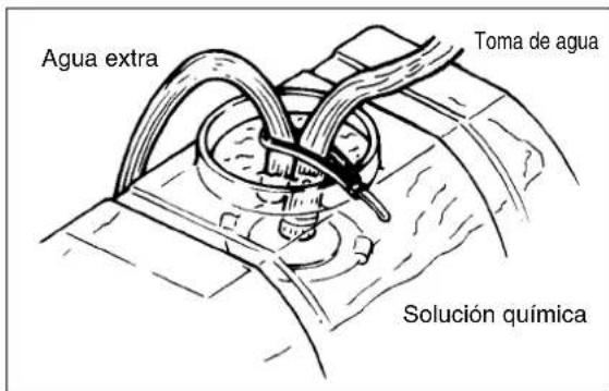
natural_image
Mechanical assembly diagram showing two vertical components with rotational arrows indicating motion (no text or symbols)natural_image
Technical line drawing of a mechanical component with internal fan structure (no text or symbols)natural_image
Mechanical assembly diagram showing two vertical components with curved arrows indicating motion or force direction (no text or symbols)
PRECAUCIÓN
natural_image
Technical line drawing of a mechanical component with no visible text or symbolsParada
natural_image
Diagram of a mechanical device pouring liquid into a bucket with a cable inserted (no text or symbols)natural_image
Illustration of a medical procedure showing a tube inserted into a bucket with arrows indicating flow direction (no text or symbols)natural_image
Technical line drawing of a mechanical valve assembly with no visible text or symbolsnatural_image
Mechanical assembly diagram showing a tool interacting with a motor and a circular component (no text or symbols)
PRECAUCIÓN
natural_image
Two workers in uniform exchanging a baby on a surface, with small crown fragments nearby (no text or symbols)natural_image
Illustration of two individuals performing CPR on a patient lying on the ground, with a first aid kit nearby (no text or symbols)natural_image
Illustration of a person standing near equipment and a fence in an open field (no text or symbols visible)1-020
natural_image
Illustration of a person standing in a field with equipment and pipes, no visible text or symbols1-021
natural_image
Cartoon illustration of a firefighter running with a baton and smoke, no text or symbols present1-015
natural_image
Cartoon illustration of a person struggling with a large cylindrical object, no text or symbols present
natural_image
Illustration of two workers operating machinery in a field, no text or symbols present1-024
natural_image
Illustration of a person washing hands with a showerhead, and another person drinking from a basin (no text or symbols)Accessoires standards
natural_image
Simple line drawing of an open book with a grid on the front page (no text or symbols)Mode d'emploi
natural_image
Simple line drawing of a curved, elongated object with no text or symbolsnatural_image
Mechanical assembly diagram showing a tool interacting with a motor and a circular component (no text or symbols)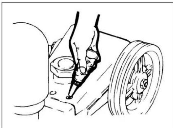
natural_image
Technical line drawing of a mechanical assembly with pulleys and a wheel (no text or symbols)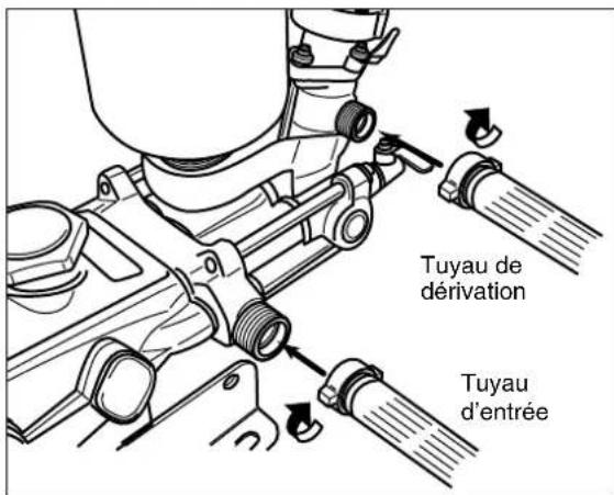
natural_image
Illustration of a bucket being inserted into a container with a hose, showing fluid flow direction (no text or symbols)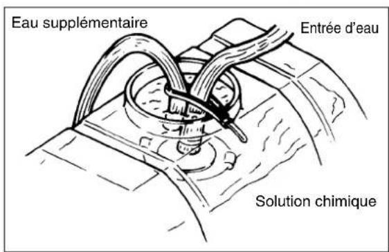
natural_image
Mechanical assembly diagram showing two vertical components with rotational arrows indicating motion (no text or symbols)natural_image
Technical line drawing of a mechanical component with internal fan structure (no text or symbols)
natural_image
Technical line drawing of mechanical components with no visible text or symbols
natural_image
Technical line drawing of a mechanical assembly with no visible text or symbolsnatural_image
Diagram of a pipe being inserted into a bucket with a hose inserted, showing fluid flow direction (no text or labels)natural_image
Diagram showing a pipe being inserted into a bucket with arrows indicating flow direction (no text or labels)ATTENTION
natural_image
Technical line drawing of a mechanical valve assembly (no text or symbols)
natural_image
Mechanical assembly diagram showing a lever and wheel mechanism with a magnified circular detail (no text or symbols)- Instruction Manual Manual de instrucciones Mode d'emploi
- Thank you very much for buying this product.
- This instruction manual describes how to use and maintain this product correctly.
- Purpose of use
- Precautions
- DANGER
- WARNING
- CAUTION
- When letting another person run this product
- For Safe Operation 2
- Part Names and Operating Parts 10
- How to Handle and Operate ....12
- Cleaning, Maintenance, and Storage 15
- Servicing 19
- Specifications 20
- For Safe Operation
- Precautions Before Getting Started
- Precautions on Safety
- These people are prohibited from spraying:
- Wear the clothes suitable for operation.
- Just In Case
- Handling of Agrichemicals
- Handling of Chemical
- Perform the operation in a timely manner.
- Precautions on Use (Inspection, Maintenance and transportation)
- Points in Operation
- Points in Handling This Machine
- Applications
- Piping
- (Water intake)
- (Spraying)
- (Hose)
- (Nozzle)
- Points on Engine Operation
- Post-use Precautions
- Part Names and Operating Parts
- Part Names
- Checking Standard Accessories
- Standard Accessories
- Product Features
- Functions of Operating Parts/Warning Label
- How to Handle and Operate
- Preparation and Check – Spraying
- This power sprayer does not contain oil. Before use, be sure to supply oil.
- Stop
- Cleaning, Maintenance, and Storage
- Remove oil after oil cools down.
- After-sale Servicing
- Changing the direction of the extra water port
- Machine Modification
- PRECAUCIÓN
- Este bomba de piston no contiene aceite. Antes de usarlo, suminístrele aceite.
- Parada
- Accessoires standards
- ATTENTION
Brand : Maruyama
Model : MS755
Category : Pump