
CE003G - Sander MAKITA - Free user manual and instructions
Find the device manual for free CE003G MAKITA in PDF.

| Product type | Cordless diamond saw (disc cutter) |
| Brand | Makita |
| Model | CE003G |
| Disc diameter | 230 mm |
| Max. disc thickness | 3.0 mm |
| Max. cutting depth | 88 mm |
| Rated speed | 6600 min⁻¹ |
| Rated voltage | 36 V - 40 V DC max. |
| Max. water supply pressure | 5 bars |
| Total length | 603 mm |
| Net weight (with battery) | 6.4 - 7.4 kg |
| Protection rating | IPX4 |
| Sound pressure level | 105 dB(A) |
| Sound power level | 116 dB(A) |
| Vibration (concrete cutting, left hand) | 3.0 m/s² (uncertainty K=1.5) |
| Vibration (concrete cutting, right hand) | 2.5 m/s² (uncertainty K=1.5) |
| Compatible batteries | BL4040, BL4040F, BL4050F, BL4080F |
| Compatible chargers | DC40RA, DC40RB, DC40RC, DC40WA |
| Portable power source | PDC1200, PDC1500 |
| Main functions | Electric brake, constant speed control, active reaction detection, accidental restart prevention, overload, overheating and deep discharge protection |
| Applications | Cutting metals with abrasive disc and masonry with diamond disc |
| Maintenance and cleaning | Regularly clean the disc cover, lamp lens and air vents |
| Spare parts and repairability | Discs, synchronous belt, flanges, batteries, chargers; repairs by authorized Makita service center |
| Safety | Protective cover, trigger with safety button, insulated handle, electric brake |
Frequently Asked Questions - CE003G MAKITA
User questions about CE003G MAKITA
0 question about this device. Answer the ones you know or ask your own.
Ask a new question about this device
Download the instructions for your Sander in PDF format for free! Find your manual CE003G - MAKITA and take your electronic device back in hand. On this page are published all the documents necessary for the use of your device. CE003G by MAKITA.
USER MANUAL CE003G MAKITA
natural_image
Technical line drawing of two mechanical components with circular and rectangular parts (no text or symbols)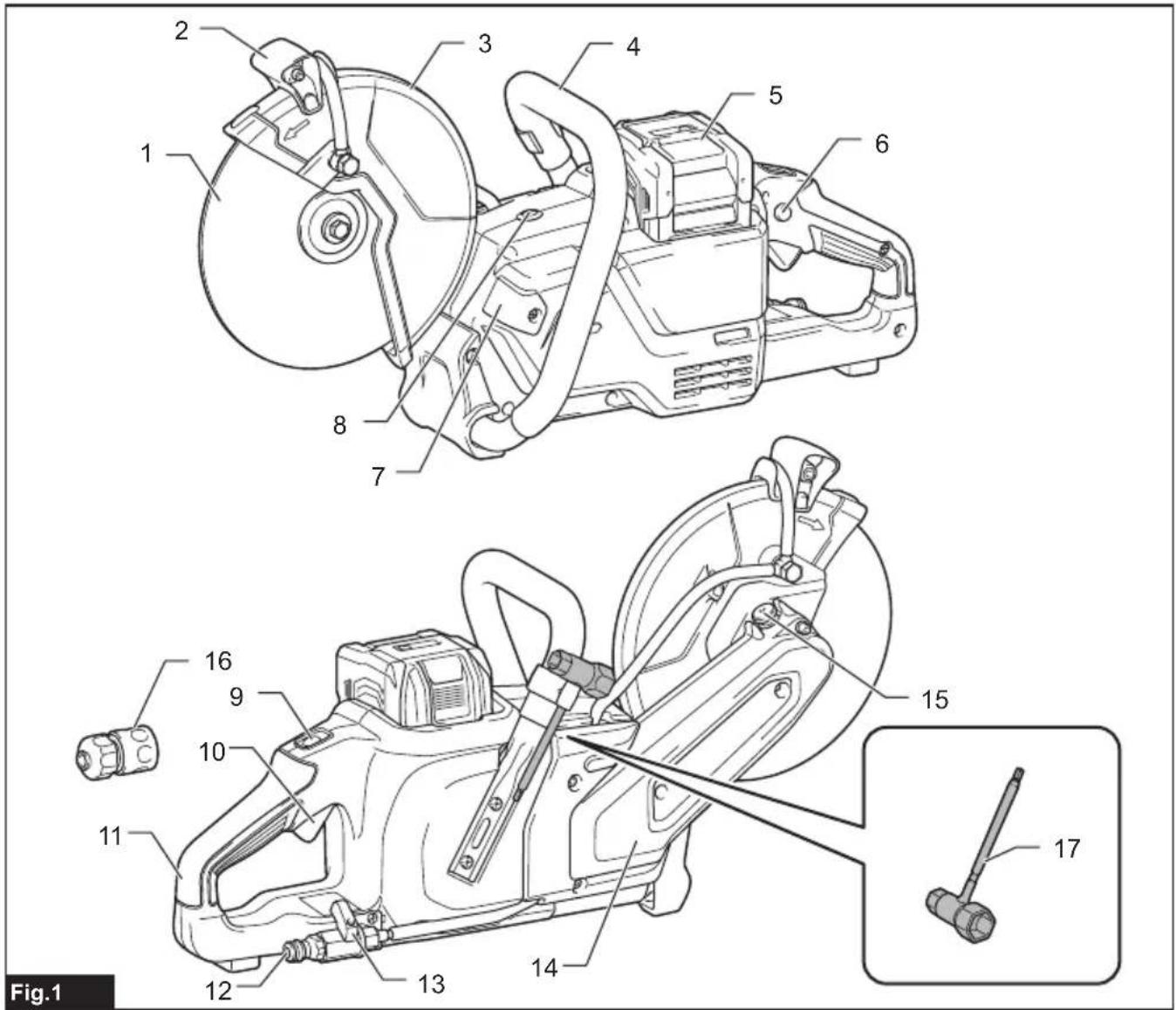

natural_image
Two technical diagrams showing a worker operating a cutting machine and another assembling a mechanical device, with no visible text or symbols.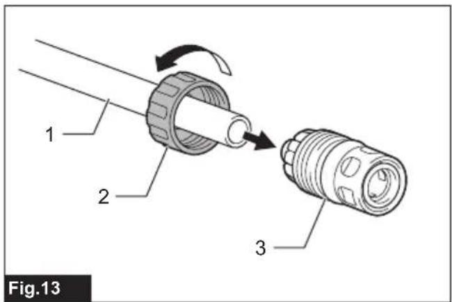
natural_image
Technical diagram of a mechanical component with directional arrows indicating flow or movement (no text or symbols)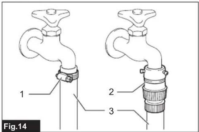
natural_image
Line drawing of hands operating a mechanical device with a tool, labeled Fig.18 (no text or symbols on the diagram itself)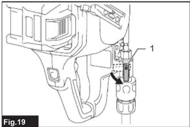
natural_image
Technical illustration of a mechanical device with no visible text or symbols, showing two views: top shows a cutting tool and bottom shows a cutting tool with a warning symbol (no text on the diagram itself)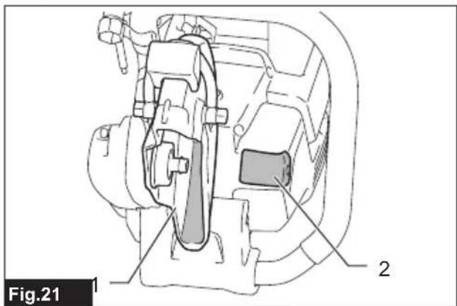
SPECIFICATIONS
| Model: CE003G CE004G | ||
| Wheel diameter 230 mm 305 mm | ||
| Max. wheel thickness 3.0 mm 5.0 mm | ||
| Max. cutting depth 88 mm 121 mm | ||
| Rated speed 6,600 min | -1 | 5,000 min^-1 |
| Rated voltage D.C. 36 V - 40 V max | ||
| Max. permitted pressure of feed-water 5 bars | ||
| Overall length 603 mm 663 mm | ||
| Net weight 6.4 - 7.4 kg 6.7 - 7.7 kg | ||
| Protection degree IPX4 | ||
• Due to our continuing program of research and development, the specifications herein are subject to change without notice.
• Specifications may differ from country to country.
- The weight may differ depending on the attachment(s), including the battery cartridge. The lightest and heaviest combinations, according to EPTA-Procedure 01/2014, are shown in the table.
Applicable battery cartridge and charger
| Battery cartridge | BL4040 / BL4040F* / BL4050F* / BL4080F* * : Recommended battery |
| Charger | DC40RA / DC40RB / DC40RC / DC40WA |
• Some of the battery cartridges and chargers listed above may not be available depending on your region of residence.
⚠ WARNING: Only use the battery cartridges and chargers listed above. Use of any other battery cartridges and chargers may cause injury and/or fire.
Recommended cord connected power source
| Portable power pack | PDC1200 / PDC1500 |
• The cord connected power source(s) listed above may not be available depending on your region of residence.
• Before using the cord connected power source, read instruction and cautionary markings on them.
Intended use
The tool is intended for cutting in metal materials with an abrasive cut-off wheel and also masonry materials with a diamond wheel.
Noise
The typical A-weighted noise level determined according to EN60745-2-22:
| Model | Sound pressure level (LpA) : (dB(A)) | Sound power level (LwA) : (dB(A)) | Uncertainty (K) : (dB(A)) |
| CE003G | 105 | 116 | 3 |
| CE004G | 99 | 110 | 3 |
NOTE: The declared noise emission value(s) has been measured in accordance with a standard test method and may be used for comparing one tool with another.
NOTE: The declared noise emission value(s) may also be used in a preliminary assessment of exposure.
WARNING: Wear ear protection.
⚠ WARNING: The noise emission during actual use of the power tool can differ from the declared value(s) depending on the ways in which the tool is used especially what kind of workpiece is processed.
WARNING: Be sure to identify safety measures to protect the operator that are based on an estimation of exposure in the actual conditions of use (taking account of all parts of the operating cycle such as the times when the tool is switched off and when it is running idle in addition to the trigger time).
Vibration
Work mode: concrete cutting
| Model Left hand Right hand Applicable | standard | ||||
| a_h,w(m/s^2) | Uncertainty K (m/s^2) | ||||
| CE003G 3.0 1.5 2.5 1.5 | EN60745-2-22 | ||||
| CE004G 3.8 1.5 2.5 1.5 | EN60745-2-22 | ||||
NOTE: The declared vibration total value(s) has been measured in accordance with a standard test method and may be used for comparing one tool with another.
NOTE: The declared vibration total value(s) may also be used in a preliminary assessment of exposure.
⚠ WARNING: The vibration emission during actual use of the power tool can differ from the declared value(s) depending on the ways in which the tool is used especially what kind of workpiece is processed.
WARNING: Be sure to identify safety measures to protect the operator that are based on an estimation of exposure in the actual conditions of use (taking account of all parts of the operating cycle such as the times when the tool is switched off and when it is running idle in addition to the trigger time).
Declarations of Conformity
For European countries only
The Declarations of conformity are included in Annex A to this instruction manual.
SAFETY WARNINGS
General power tool safety warnings
⚠ WARNING Read all safety warnings, instructions, illustrations and specifications provided with this power tool. Failure to follow all instructions listed below may result in electric shock, fire and/or serious injury.
Save all warnings and instructions for future reference.
The term "power tool" in the warnings refers to your mains-operated (corded) power tool or battery-operated (cordless) power tool.
Cordless cutter safety warnings
- The guard provided with the tool must be securely attached to the power tool and positioned for maximum safety, so the least amount of wheel is exposed towards the operator. Position yourself and bystanders away from the plane of the rotating wheel. The guard helps to protect operator from broken wheel fragments and accidental contact with wheel.
-
Use only bonded reinforced or diamond cut-off wheels for your power tool. Just because an accessory can be attached to your power tool, it does not assure safe operation.
-
The rated speed of the accessory must be at least equal to the maximum speed marked on the power tool. Accessories running faster than their rated speed can break and fly apart.
- Wheels must be used only for recommended applications. For example: do not grind with the side of cut-off wheel. Abrasive cut-off wheels are intended for peripheral grinding, side forces applied to these wheels may cause them to shatter.
- Always use undamaged wheel flanges that are of correct diameter for your selected wheel. Proper wheel flanges support the wheel thus reducing the possibility of wheel breakage.
- Do not use worn down reinforced wheels from larger power tools. Wheels intended for a larger power tool are not suitable for the higher speed of a smaller tool and may burst.
- The outside diameter and the thickness of your accessory must be within the capacity rating of your power tool. Incorrectly sized accessories cannot be adequately guarded or controlled.
- The arbour size of wheels and flanges must properly fit the spindle of the power tool. Wheels and flanges with arbour holes that do not match the mounting hardware of the power tool will run out of balance, vibrate excessively and may cause loss of control.
-
Do not use damaged wheels. Before each use, inspect the wheels for chips and cracks. If power tool or wheel is dropped, inspect for damage or install an undamaged wheel. After inspecting and installing the wheel, position yourself and bystanders away from the plane of the rotating wheel and run the power tool at maximum no load speed for one minute. Damaged wheels will normally break apart during this test time.
-
Wear personal protective equipment. Depending on application, use face shield, safety goggles or safety glasses. As appropriate, wear dust mask, hearing protectors, gloves and shop apron capable of stopping small abrasive or workpiece fragments. The eye protection must be capable of stopping flying debris generated by various operations. The dust mask or respirator must be capable of filtrating particles generated by your operation. Prolonged exposure to high intensity noise may cause hearing loss.
- Keep bystanders a safe distance away from work area. Anyone entering the work area must wear personal protective equipment. Fragments of workpiece or of a broken wheel may fly away and cause injury beyond immediate area of operation.
- Hold the power tool by insulated gripping surfaces only, when performing an operation where the cutting accessory may contact hidden wiring. Cutting accessory contacting a "live" wire may make exposed metal parts of the power tool "live" and could give the operator an electric shock.
- Never lay the power tool down until the accessory has come to a complete stop. The spinning wheel may grab the surface and pull the power tool out of your control.
- Do not run the power tool while carrying it at your side. Accidental contact with the spinning accessory could snag your clothing, pulling the accessory into your body.
- Regularly clean the power tool's air vents. The motor's fan will draw the dust inside the housing and excessive accumulation of powdered metal may cause electrical hazards.
- Do not operate the power tool near flammable materials. Sparks could ignite these materials.
Kickback and related warnings
Kickback is a sudden reaction to a pinched or snagged rotating wheel. Pinching or snagging causes rapid stalling of the rotating wheel which in turn causes the uncontrolled power tool to be forced in the direction opposite of the wheel's rotation at the point of the binding.
For example, if an abrasive wheel is snagged or pinched by the workpiece, the edge of the wheel that is entering into the pinch point can dig into the surface of the material causing the wheel to climb out or kick out. The wheel may either jump toward or away from the operator, depending on direction of the wheel's movement at the point of pinching. Abrasive wheels may also break under these conditions. Kickback is the result of power tool misuse and/or incorrect operating procedures or conditions and can be avoided by taking proper precautions as given below.
- Maintain a firm grip on the power tool and position your body and arm to allow you to resist kickback forces. Always use auxiliary handle, if provided, for maximum control over kickback or torque reaction during start-up. The operator can control torque reactions or kickback forces, if proper precautions are taken.
- Never place your hand near the rotating accessory. Accessory may kickback over your hand.
-
Do not position your body in line with the rotating wheel. Kickback will propel the tool in direction opposite to the wheel's movement at the point of snagging.
-
Use special care when working corners, sharp edges etc. Avoid bouncing and snagging the accessory. Corners, sharp edges or bouncing have a tendency to snag the rotating accessory and cause loss of control or kickback.
- Do not attach a saw chain, woodcarving blade, segmented diamond wheel with a peripheral gap greater than 10 mm or toothed saw blade. Such blades create frequent kickback and loss of control.
- Do not "jam" the wheel or apply excessive pressure. Do not attempt to make an excessive depth of cut. Overstressing the wheel increases the loading and susceptibility to twisting or binding of the wheel in the cut and the possibility of kickback or wheel breakage.
- When wheel is binding or when interrupting a cut for any reason, switch off the power tool and hold the power tool motionless until the wheel comes to a complete stop. Never attempt to remove the wheel from the cut while the wheel is in motion otherwise kickback may occur. Investigate and take corrective action to eliminate the cause of wheel binding.
- Do not restart the cutting operation in the workpiece. Let the wheel reach full speed and carefully re-enter the cut. The wheel may bind, walk up or kickback if the power tool is restarted in the workpiece.
- Support panels or any oversized workpiece to minimize the risk of wheel pinching and kick-back. Large workpieces tend to sag under their own weight. Supports must be placed under the workpiece near the line of cut and near the edge of the workpiece on both sides of the wheel.
- Use extra caution when making a "pocket cut" into existing walls or other blind areas. The protruding wheel may cut gas or water pipes, electrical wiring or objects that can cause kickback.
Additional Safety Warnings:
- Before using a segmented diamond wheel, make sure that the diamond wheel has the peripheral gap between segments of 10 mm or less, only with a negative rake angle.
- Never attempt to cut with the tool held upside down in a vise. This can lead to serious accidents, because it is extremely dangerous.
- Some material contains chemicals which may be toxic. Take caution to prevent dust inhalation and skin contact. Follow material supplier safety data.
- Store wheels as per manufacturer recommendations. Improper storage may damage the wheels.
- Always use the wheel suitable for your work and the material to be cut.
- Examine the material to be cut before cutting. If the material contains explosive or flammable substances, it may cause an explosion or fire.
- Do not switch on the tool if a foreign object is jammed between the guard and the wheel. In this case, uninstall the battery cartridge and remove the foreign object.
- Use clamps or similar to support the workpiece whenever possible.
- Always wear hearing protection during operation.
- Do not cut wood materials with this tool.
-
The outside diameter and the thickness of the wheel must be within the capacity rating of your power tool. Incorrectly sized wheels cannot be adequately guarded or controlled.
-
When operating the power tool, maintain a firm grip with both hands on the power tool and position your body and arm to allow you to resist kickback forces.
- Keep your hands or face away from the rotating wheel.
- Adjust the wheel cover to a position suitable for your work.
- When you use the tool on muddy ground, wet slope, or slippery place, pay attention to your footing.
- Do not submerge the tool into a puddle.
- Do not leave the tool unattended outdoors in the rain.
- Do not replace the battery in the rain.
- When storing the tool, avoid direct sunlight and rain, and store it in a place where it does not get hot or humid.
SAVE THESE INSTRUCTIONS.
WARNING: DO NOT let comfort or familiarity with product (gained from repeated use) replace strict adherence to safety rules for the subject product. MISUSE or failure to follow the safety rules stated in this instruction manual may cause serious personal injury.
Important safety instructions for battery cartridge
- Before using battery cartridge, read all instructions and cautionary markings on (1) battery charger, (2) battery, and (3) product using battery.
- Do not disassemble or tamper with the battery cartridge. It may result in a fire, excessive heat, or explosion.
- If operating time has become excessively shorter, stop operating immediately. It may result in a risk of overheating, possible burns and even an explosion.
-
If electrolyte gets into your eyes, rinse them out with clear water and seek medical attention right away. It may result in loss of your eyesight.
-
Do not short the battery cartridge:
(1) Do not touch the terminals with any conductive material.
(2) Avoid storing battery cartridge in a container with other metal objects such as nails, coins, etc.
(3) Do not expose battery cartridge to water or rain.
A battery short can cause a large current flow, overheating, possible burns and even a breakdown.
-
Do not store and use the tool and battery cartridge in locations where the temperature may reach or exceed 50 °C (122 °F).
-
Do not incinerate the battery cartridge even if it is severely damaged or is completely worn out. The battery cartridge can explode in a fire.
-
Do not nail, cut, crush, throw, drop the battery cartridge, or hit against a hard object to the battery cartridge. Such conduct may result in a fire, excessive heat, or explosion.
-
Do not use a damaged battery.
-
The contained lithium-ion batteries are subject to the Dangerous Goods Legislation requirements. For commercial transports e.g. by third parties, forwarding agents, special requirement on packaging and labeling must be observed.
For preparation of the item being shipped, consulting an expert for hazardous material is required. Please also observe possibly more detailed national regulations.
Tape or mask off open contacts and pack up the battery in such a manner that it cannot move around in the packaging. -
When disposing the battery cartridge, remove it from the tool and dispose of it in a safe place. Follow your local regulations relating to disposal of battery.
-
Use the batteries only with the products specified by Makita. Installing the batteries to non-compliant products may result in a fire, excessive heat, explosion, or leak of electrolyte.
-
If the tool is not used for a long period of time, the battery must be removed from the tool.
-
During and after use, the battery cartridge may take on heat which can cause burns or low temperature burns. Pay attention to the handling of hot battery cartridges.
-
Do not touch the terminal of the tool immediately after use as it may get hot enough to cause burns.
-
Do not allow chips, dust, or soil stuck into the terminals, holes, and grooves of the battery cartridge. It may cause heating, catching fire, burst and malfunction of the tool or battery cartridge, resulting in burns or personal injury.
-
Unless the tool supports the use near high-voltage electrical power lines, do not use the battery cartridge near high-voltage electrical power lines. It may result in a malfunction or breakdown of the tool or battery cartridge.
-
Keep the battery away from children.
SAVE THESE INSTRUCTIONS.
CAUTION: Only use genuine Makita batteries. Use of non-genuine Makita batteries, or batteries that have been altered, may result in the battery bursting causing fires, personal injury and damage. It will also void the Makita warranty for the Makita tool and charger.
Tips for maintaining maximum battery life
- Charge the battery cartridge before completely discharged. Always stop tool operation and charge the battery cartridge when you notice less tool power.
- Never recharge a fully charged battery cartridge. Overcharging shortens the battery service life.
- Charge the battery cartridge with room temperature at 10 °C - 40 °C ( 50 °F - 104 °F ). Let a hot battery cartridge cool down before charging it.
- When not using the battery cartridge, remove it from the tool or the charger.
- Charge the battery cartridge if you do not use it for a long period (more than six months).
PARTS DESCRIPTION
▶ Fig.1
| 1 Abrasive cut-off wheel / diamond wheel | 2 | Wheel cover grip | 3 | Wheel guard | 4 | Grip |
| 5 Battery cartridge | 6 | Lock-off button | 7 | Lamp | 8 | Overload indicator |
| 9 Lamp button | 10 | Switch trigger | 11 | Handle | 12 | Water inlet |
| 13 Cock | 14 | Cover (for synchro-belt) | 15 | Shaft lock button | 16 | Coupling sleeve |
| 17 Box wrench (hex wrench-shaped handle tip) |
FUNCTIONAL DESCRIPTION
⚠️CAUTION: Always be sure that the tool is switched off and the battery cartridge is removed before adjusting or checking function on the tool.
Installing or removing the battery cartridge
⚠️CAUTION: Always switch off the tool before installing or removing the battery cartridge.
⚠️CAUTION: Hold the tool and the battery cartridge firmly when installing or removing the battery cartridge. Failure to hold the tool and the battery cartridge firmly may cause them to slip out of your hands and result in damage to the tool and battery cartridge and personal injury.
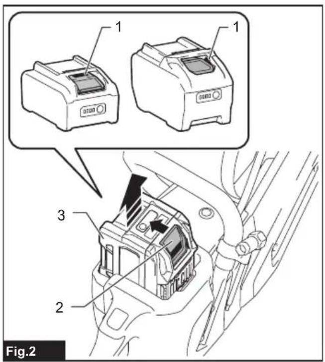
To install the battery cartridge, align the tongue on the battery cartridge with the groove in the housing and slip it into place. Insert it all the way until it locks in place with a little click. If you can see the red indicator as shown in the figure, it is not locked completely.
To remove the battery cartridge, lift the battery cartridge while pushing the button on the front of the cartridge.
▶ Fig.2: 1. Red indicator 2. Button 3. Battery cartridge
⚠️CAUTION: Always install the battery cartridge fully until the red indicator cannot be seen. If not fully installed, it may accidentally fall out of the tool, causing injury to you or someone around you.
⚠️CAUTION: Do not install the battery cartridge forcibly. If the cartridge does not slide in easily, it is not being inserted correctly.
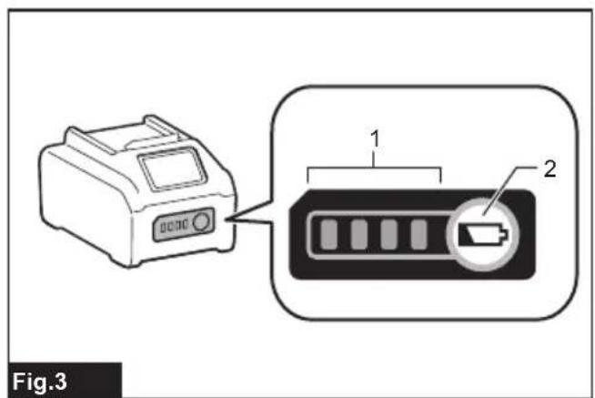
Indicating the remaining battery capacity
Press the check button on the battery cartridge to indicate the remaining battery capacity. The indicator lamps light up for a few seconds.
▶ Fig.3: 1. Indicator lamps 2. Check button
| Indicator lamps | Remaining capacity | ||
| Lighted | Off | Blinking | |
| 75% to 100% | |||
| 50% to 75% | |||
| 25% to 50% | |||
| 0% to 25% | |||
| Charge the battery. | |||
| The battery may have malfunctioned. | |||
NOTE: Depending on the conditions of use and the ambient temperature, the indication may differ slightly from the actual capacity.
NOTE: The first (far left) indicator lamp will blink when the battery protection system works.
Tool / battery protection system
The tool is equipped with a tool/battery protection system. This system automatically cuts off power to the motor to extend tool and battery life. The tool will automatically stop during operation if the tool or battery is placed under one of the following conditions.
Overload protection
When the tool/battery is operated in a manner that causes it to draw an abnormally high current, the tool automatically stops. In this situation, turn the tool off and stop the application that caused the tool to become overloaded. Then turn the tool on to restart.
Overheat protection
When the tool/battery is overheated, the tool stops automatically, and the lamp blinks. In this situation, let the tool cool down before turning the tool on again.
Overdischarge protection
When the battery capacity becomes low, the tool stops automatically, and the indicator lamp of battery cartridge blinks. If the tool does not operate even when the switches are operated, remove the batteries from the tool and charge the batteries.
Protections against other causes
Protection system is also designed for other causes that could damage the tool and allows the tool to stop automatically. Take all the following steps to clear the causes, when the tool has been brought to a temporary halt or stop in operation.
- Turn the tool off, and then turn it on again to restart.
- Charge the battery(ies) or replace it/them with recharged battery(ies).
- Let the tool and battery(ies) cool down.
If no improvement can be found by restoring protection system, then contact your local Makita Service Center.
NOTICE: If the tool stops due to a cause not described above, refer to the section for troubleshooting.
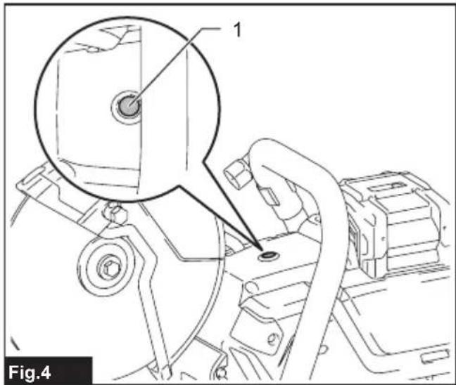
Overload alert
If the tool is operated with excessive load, the overload indicator will blink in red. In this situation, reduce the load on the tool. Then, the indicator stops blinking.
▶ Fig.4: 1. Overload indicator
Switch action
⚠ WARNING: Before installing the battery cartridge into the tool, always check to see that the switch trigger actuates properly and returns to the "OFF" position when released.
WARNING: NEVER defeat the lock-off button by taping down or some other means. A switch with a negated lock-off button may result in unintentional operation and serious personal injury.
WARNING: NEVER use the tool if it runs when you simply pull the switch trigger without pressing the lock-off button. A switch in need of repair may result in unintentional operation and serious personal injury. Return tool to a Makita service center for proper repairs BEFORE further usage.
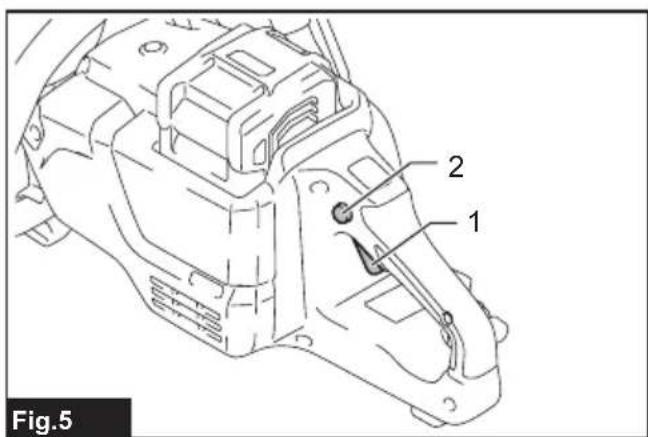
To prevent the switch trigger from being accidentally pulled, a lock-off button is provided. To start the tool, depress the lock-off button and pull the switch trigger. Release the switch trigger to stop.
▶ Fig.5: 1. Switch trigger 2. Lock-off button
NOTICE: Do not pull the switch trigger hard without pressing in the lock-off button. This can cause switch breakage.
Lighting the lamp
⚠️ CAUTION: Do not look into the light or look directly at the light source.
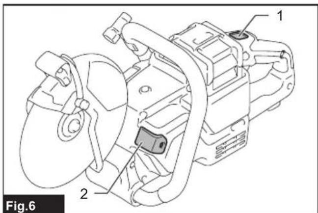
To turn on the lamp, press the lamp button. To turn off the lamp, press the lamp button again.
▶ Fig.6: 1. Lamp button 2. Lamp
NOTE: The lamp will automatically turn off if there is no operation with the tool for one minute.
Adjusting the wheel cover
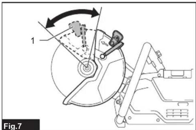
Hold the wheel cover grip and adjust the position of the wheel cover so it is suitable for your work.
▶ Fig.7: 1. Wheel cover grip
Electronic function
The tool is equipped with following electronic function for easy operation.
Electric brake
This tool is equipped with an electric brake. If the tool consistently fails to quickly stop after the switch trigger is released, have the tool serviced at a Makita service center.
Active Feedback sensing Technology
The tool electronically detects situations where the wheel or accessory may be at risk to be bound. In the situation, the tool is automatically shut off to prevent further rotation of the spindle (it does not prevent kick-back).
To restart the tool, switch off the tool first, remove the cause of the sudden drop in the rotation speed, and then turn the tool on again.
Constant speed control
The speed control function provides the constant rotation speed regardless of load conditions.
Accidental re-start preventive function
The tool does not start when the battery is installed while the switch is set to ON. To start the tool, turn off the switch, and turn it on again.
ASSEMBLY
⚠️CAUTION: Always be sure that the tool is switched off and the battery cartridge is removed before carrying out any work on the tool.
Installing or removing the abrasive cut-off wheel / diamond wheel
⚠️CAUTION: Use only the Makita wrench to install or remove the wheel.
⚠️CAUTION: When installing the wheel, be sure to tighten the bolt securely.
⚠️CAUTION: Do not press the shaft lock button when the wheel is rotating.
NOTICE: Do not use wheels that are severely damaged, worn, or whose expiration date has passed. Malfunction, abnormal noise, or breakage may occur.
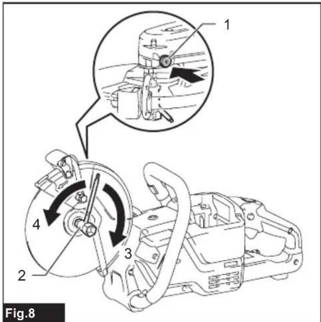
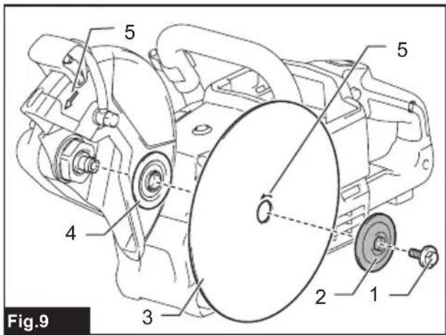
To remove the wheel, press the shaft lock button and rotate the wheel until the wheel cannot revolve. While the shaft lock is fully locked, turn the hex bolt counterclockwise using the box wrench. Then remove the hex bolt, outer flange and wheel.
▶ Fig.8: 1. Shaft lock button 2. Box wrench 3. Tighten 4. Loosen
▶ Fig.9: 1. Hex bolt 2. Outer flange (black) 3. Abrasive cut-off wheel / diamond wheel 4. Inner flange (silver) 5. Arrow (rotation direction of the wheel)
To install the wheel, follow the removal procedure in reverse. BE SURE TO TIGHTEN THE HEX BOLT SECURELY.
CAUTION: Always install the wheel so that the arrow on it points in the same direction as the arrow on the wheel guard. Otherwise, the wheel rotates in reverse, which may cause personal injury.
⚠️CAUTION: Only use a wheel that is marked with a speed equal to or higher than the speed marked on the tool.
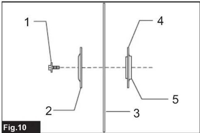
NOTE: If an inner flange is removed by chance, install the inner flange so that taller protrusion faces the tool side as shown in the figure.
CE003G (for the abrasive cut-off wheel / diamond wheel)
▶ Fig.10: 1. Hex bolt 2. Outer flange 46 (black) 3. Abrasive cut-off wheel / diamond wheel 4. Inner flange 46 (silver) 5. Protrusion (taller)
CE004G (for the diamond wheel)
▶ Fig.11: 1. Hex bolt 2. Flange 50 (black) 3. Ring
4. Diamond wheel
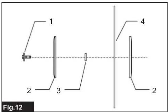
CE004G (for the abrasive cut-off wheel)
▶ Fig.12: 1. Hex bolt 2. Flange 80 (black) 3. Ring
4. Abrasive cut-off wheel
Connecting to water supply
- Prepare a water hose.
- Remove the nut on the coupling sleeve and pass the water hose through the nut. Insert the end of the hose into the coupling sleeve and then tighten the nut.
▶ Fig.13: 1. Water hose 2. Nut of the coupling sleeve 3. Coupling sleeve
- Connect the water hose to the water supply.
When connecting to a water faucet, use a suitable fitting such as hose band or water tap joint.
▶ Fig.14: 1. Hose band 2. Water tap joint 3. Water hose
NOTE: The fitting depends on the shape of the faucet to which you connect. Prepare a suitable commercially-bought fitting.
NOTE: If you use a water tap joint, prepare another coupling sleeve and attach it to the other end of the hose.
NOTE: When using a water pump, follow the instructions of your water pump to connect the water hose.
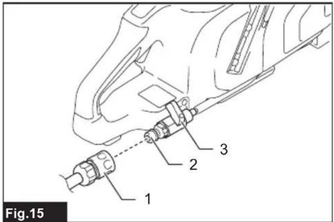
- Push the coupling sleeve into the water inlet until it locks with a click.
▶ Fig.15: 1. Coupling sleeve 2. Water inlet 3. Cock
NOTICE: Keep the cock closed until you start the cutting operation with water feeding. For how to feed water, refer to the section for the operation.
OPERATION
CAUTION: Be sure to hold the workpiece firmly down on a stable bench or table during operation.
CAUTION: Do not twist or force the tool in the cut, or else the motor may be overloaded or the workpiece may break.
CAUTION: Do not touch the wheel or workpiece immediately after operation, as they may become hot and may cause burns.
Cutting
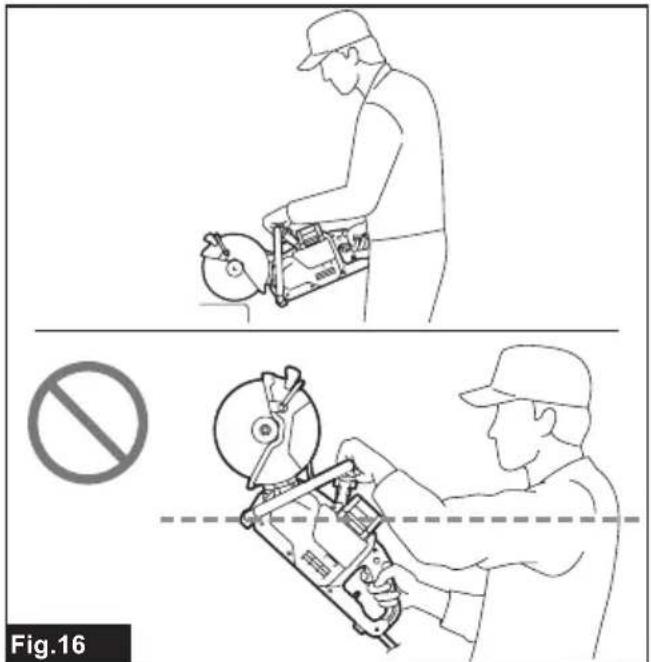
CAUTION: During operation, do not bring the tool higher than your shoulder height.
▶ Fig.16
Hold the tool firmly. Grasp the handle with your right hand and the grip with your left hand. To prevent electric shock by accidental cutting of an electric cable, always hold the grip by the designated portion as shown in the figure.
▶ Fig.17: 1. Part to hold
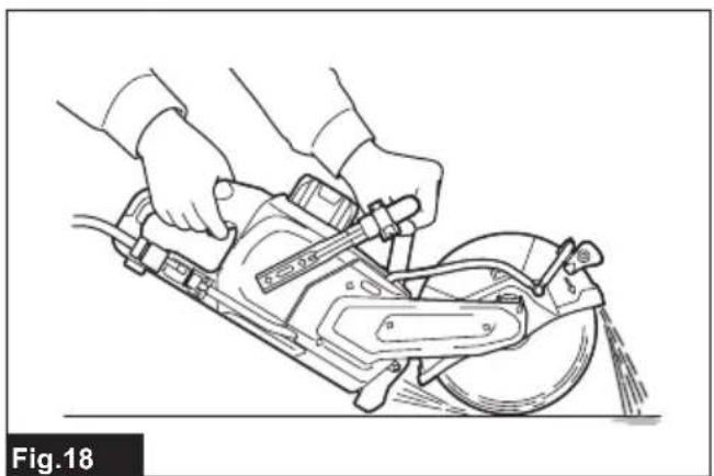
Move the tool over the workpiece surface, keeping it flat and advancing smoothly until the cutting is completed. Keep your cutting line straight and your speed of advance uniform.
▶ Fig.18
NOTE: When the battery cartridge temperature is low, the tool may not work to its full capacity. At this time, for example, use the tool for a light-duty cut for a while until the battery cartridge warms up as high as room temperature. Then, the tool can work to its full capacity.
NOTE: If the cutting action of the diamond wheel begins to diminish, dress the cutting edge of the wheel using an old discarded coarse grit bench grinder wheel or concrete block. Dress by pressing lightly on the outer edge of the diamond wheel.
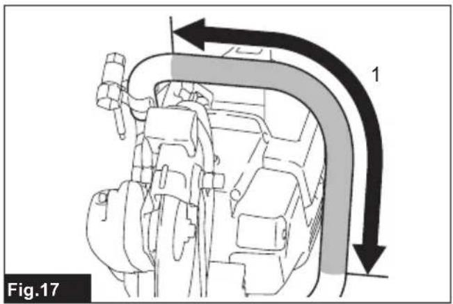
When feeding water during cutting
CAUTION: When using a wet-type diamond wheel, always feed water during cutting.
Connect the tool to the water supply and turn the cock in the direction of the arrow as illustrated. Adjust the position of the cock to obtain a gentle flow of water.
▶ Fig.19: 1. Cock
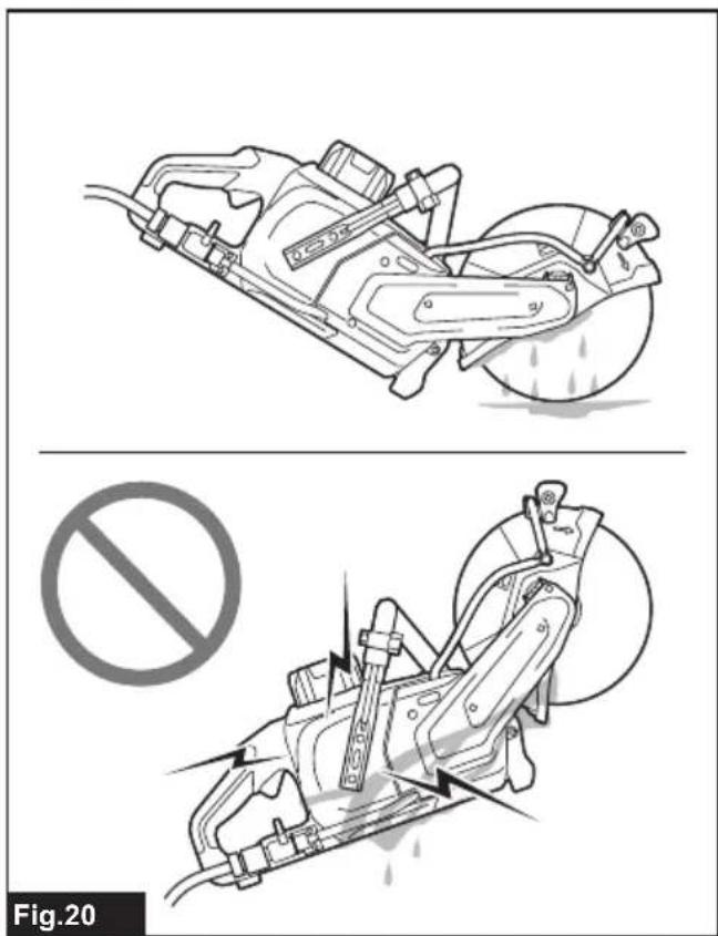
⚠️CAUTION: When feeding water, always keep the tool head lower than the tool body to prevent water entering into the tool mechanism. Failure to do so may cause electric shock.
▶ Fig.20
MAINTENANCE
⚠️CAUTION: Always be sure that the tool is switched off and the battery cartridge is removed before attempting to perform inspection or maintenance.
NOTICE: Never use gasoline, benzine, thinner, alcohol or the like. Discoloration, deformation or cracks may result.
To maintain product SAFETY and RELIABILITY, repairs, any other maintenance or adjustment should be performed by Makita Authorized or Factory Service Centers, always using Makita replacement parts.
Cleaning the tool
After each use, remove the battery cartridge and the wheel and then clean dust, dirt or metal chips accumulated inside the wheel guard. Clean the tool body by wiping off dust, dirt with a dry cloth or one dipped in soapy water and wrung out. Use a dry cloth to wipe the dirt off the lens of the lamp. Be careful not to scratch the lens of lamp, or it may lower the illumination.
▶ Fig.21: 1. Wheel guard 2. Lens of the lamp
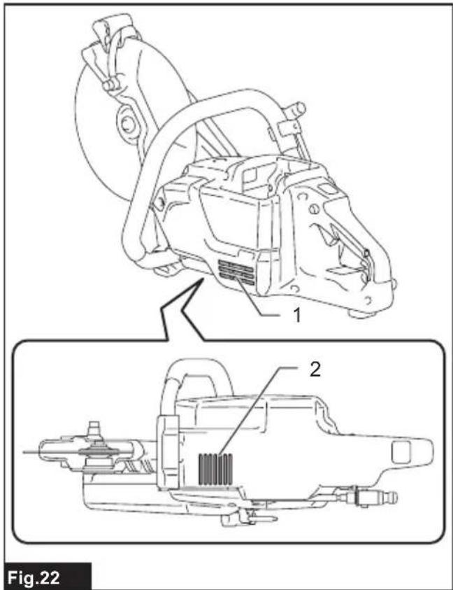
Cleaning the air vent
Regularly clean the tool's air vents or whenever the vents start to become obstructed.
▶ Fig.22: 1. Inhalation vent 2. Exhaust vent
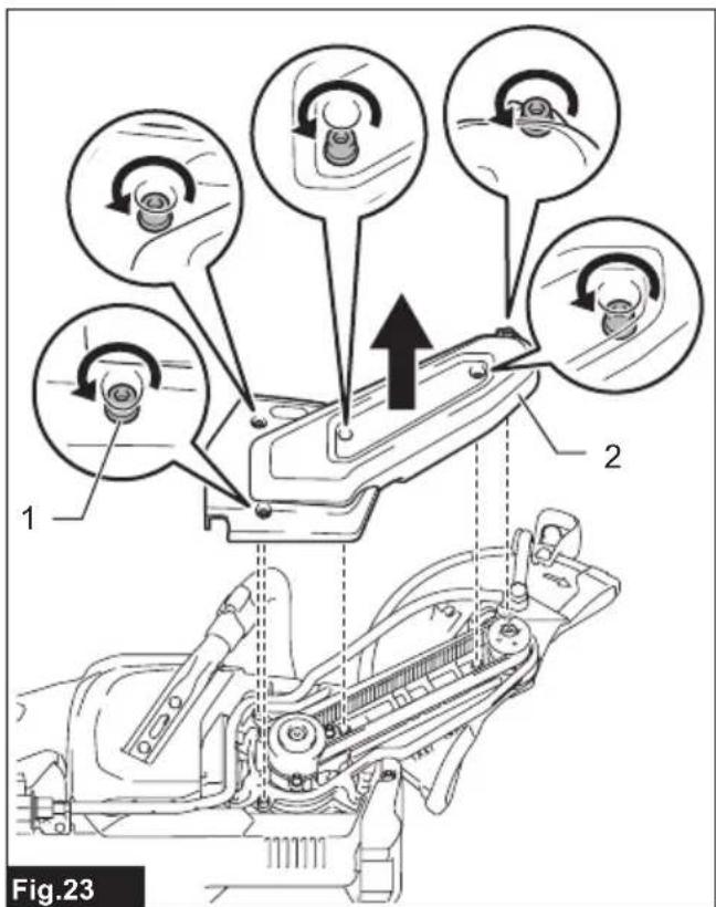
Changing the synchro-belt
- Remove the battery cartridge and the wheel.
- Loosen the hex socket bolts using box wrench handle and then remove the cover.
▶ Fig.23: 1. Hex socket bolt 2. Cover
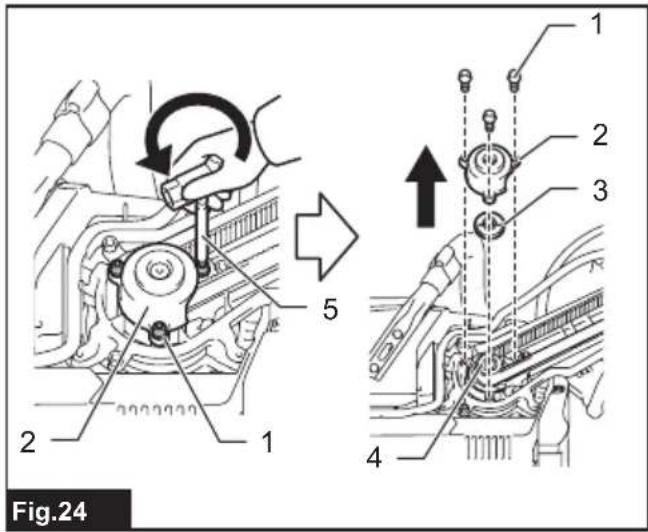
- Turn the hex socket bolts on the cover of pulley (driving) counterclockwise using box wrench handle and then remove the cover and the plate on the pully.
▶ Fig.24: 1. Hex socket bolt 2. Cover 3. Plate 4. Pulley (driving) 5. Box wrench (hex wrench-shaped handle tip)
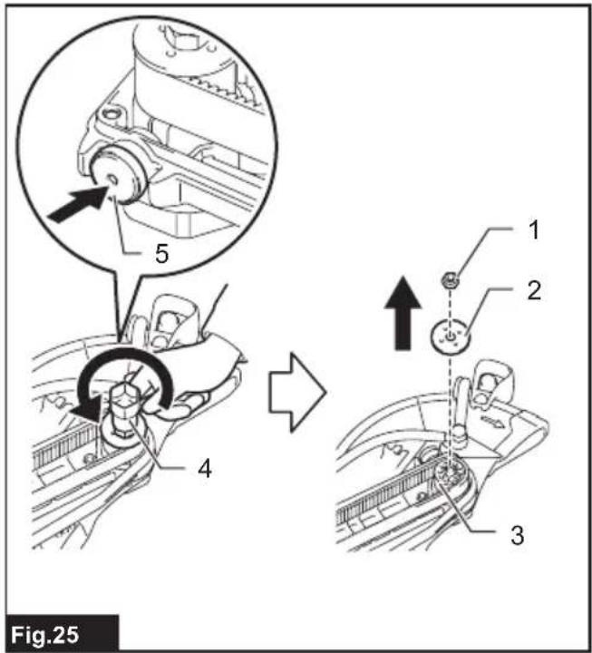
- Push in the shaft lock button and hold it to lock the pulley (driven), turn the nut on the pulley (driven) counterclockwise using the box wrench, and then remove the nut and the plate on the pully.
▶ Fig.25: 1. Nut 2. Plate 3. Pulley (driven) 4. Box wrench 5. Shaft lock button
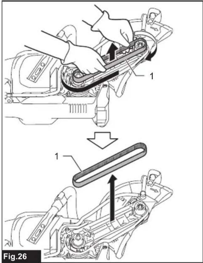
- Move the synchro-belt around the pulleys to the right while pulling up until the synchro-belt comes off.
▶ Fig.26: 1. Synchro-belt
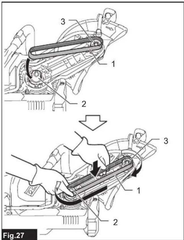
- Hook the new synchro-belt on the teeth of the pulley (driven), with the teeth of the belt facing inside. Put the other end of the synchro-belt onto the pulley (driving) so that it is partially hooked on the teeth of the pulley. After that, move the synchro-belt around the pulleys to the right. The synchro-belt will get on the track as you turn.
▶ Fig.27: 1. Synchro-belt 2. Pulley (driving) 3. Pulley (driven)
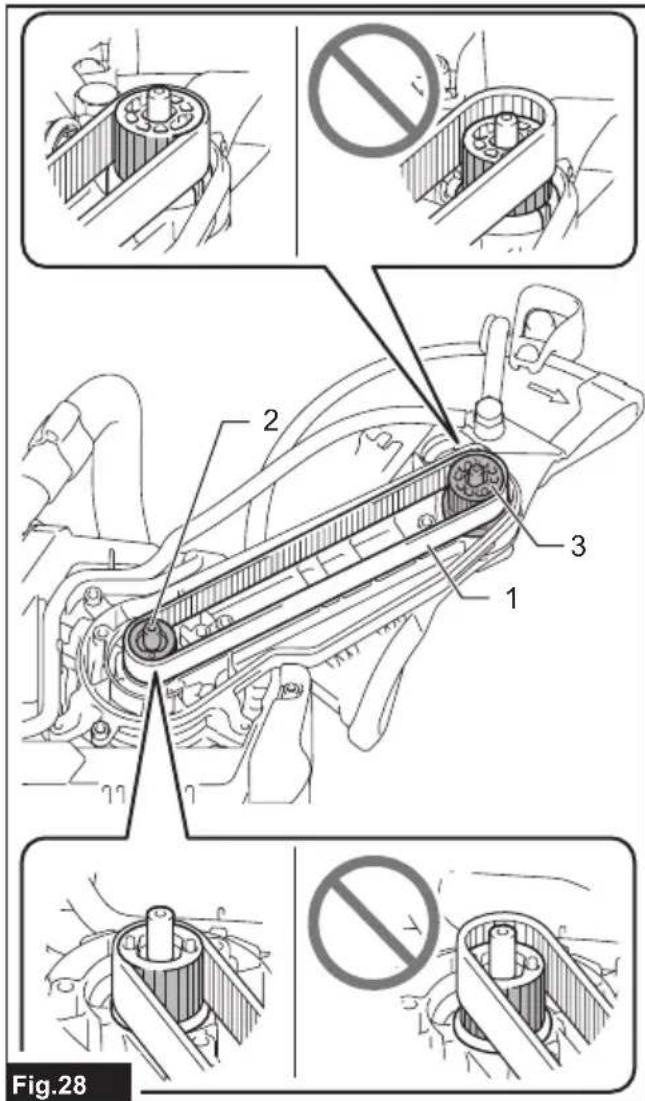
- Make sure that all the teeth on the internal circle of the synchro-belt fit into the teeth on the pulleys. Move the synchro-belt around the pulleys and check for any abnormal noise or vibration.
▶ Fig.28: 1. Synchro-belt 2. Pulley (driving) 3. Pulley (driven)
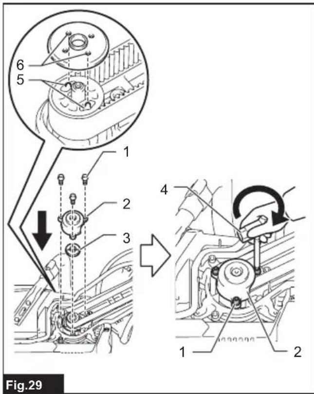
- Align the pins on the pulley (driving) and the holes in the plate firmly, then put the cover on and tighten the hex socket bolts using box wrench handle.
▶ Fig.29: 1. Hex socket bolt 2. Cover 3. Plate 4. Box wrench (hex wrench-shaped handle tip) 5. Pins on the pulley 6. Holes in the plate
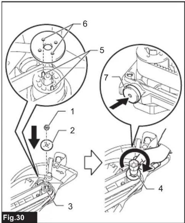
- Align the pins on the pulley (driven) and the holes in the plate firmly, then push in the shaft lock button and hold it to lock the pulley (driven), and tighten the nut using the box wrench.
▶ Fig.30: 1. Nut 2. Plate 3. Pulley (driven) 4. Box wrench 5. Pins on the pulley 6. Holes in the plate 7. Shaft lock button
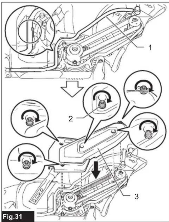
- Place the cover onto the tool and tighten the hex socket bolts using the box wrench handle.
▶ Fig.31: 1. Tube 2. Hex socket bolt 3. Cover
NOTICE: Make sure that the tube for water feed is in the positions as shown in the figure before attaching the cover.
- Install the battery.
- Operate the tool with no load and check that there is no abnormal noise, abnormal vibration, or heat generation.
TROUBLESHOOTING
Before asking for repairs, conduct your own inspection first. If you find a problem that is not explained in the manual, do not attempt to dismantle the tool. Instead, ask Makita Authorized Service Centers, always using Makita replacement parts for repairs.
| State of abnormality Probable cause | (malfunction) Remedy | |
| Motor does not run. Battery cartridge is | not installed. Install the battery cartridge. | |
| Battery problem (under voltage) Recharge the battery. If recharging is not effective, replace the battery cartridge. | ||
| The drive system does not work correctly. | Ask your local authorized service center for repair. | |
| Motor stops running after a little use. | Battery's charge level is low. | Recharge the battery. If recharging is not effective, replace the battery cartridge. |
| Overheating. Stop using of tool to allow it to cool down. | ||
| The wheel rotation does not accelerate properly even after running the tool without load for 20 seconds. | Battery is installed improperly. Install the battery cartridge as described in this manual. | |
| Battery power is dropping. Recharge the battery cartridge. If recharging is not effective, replace the battery cartridge. | ||
| The synchro-belt is slipping. Replace the synchro-belt with new one. | ||
| The drive system does not work correctly. | Ask your local authorized service center for repair. | |
| Wheel does not rotate: → stop the machine immediately! | The synchro-belt is slipping. Replace the synchro-belt with new one. | |
| Foreign object is jammed between the guard and the wheel. | Uninstall the battery cartridge and then remove the foreign object. | |
| The drive system does not work correctly. | Ask your local authorized service center for repair. | |
| Abnormal vibration: → stop the machine immediately! | Improper attachment of the wheel. Install the wheel as instructed in this manual. Tighten the bolt to secure the wheel firmly. | |
| The drive system does not work correctly. | Ask your local authorized service center for repair. | |
| Cutting tool and motor cannot stop: → Remove the battery cartridge immediately! | Electric or electronic malfunction. Remove the battery cartridge and ask your local authorized service center for repair. | |
| Poor cutting performance It is time to replace the wheel. Replace the wheel with new one. | ||
| Water leaks from the inlet. | Water is leaking from the O-ring part. | Ask your local authorized service center for repair. |
OPTIONAL ACCESSORIES
⚠️CAUTION: These accessories or attachments are recommended for use with your Makita tool specified in this manual. The use of any other accessories or attachments might present a risk of injury to persons. Only use accessory or attachment for its stated purpose.
If you need any assistance for more details regarding these accessories, ask your local Makita Service Center.
• Abrasive cut-off wheel
- Diamond wheel
- Synchro-belt
- Coupling sleeve
• Makita genuine battery and charger
NOTE: Some items in the list may be included in the tool package as standard accessories. They may differ from country to country.
SPÉCIFICATIONS
⚠ WAARSCHUWING: Draag gehoorbescherming.
VEILIGHEIDSWAAR- SCHUWINGEN
▶ Fig.6: 1. Lampknop 2. Lamp