
BTS250C - Lighting BeamZ - Free user manual and instructions
Find the device manual for free BTS250C BeamZ in PDF.

User questions about BTS250C BeamZ
0 question about this device. Answer the ones you know or ask your own.
Ask a new question about this device
Download the instructions for your Lighting in PDF format for free! Find your manual BTS250C - BeamZ and take your electronic device back in hand. On this page are published all the documents necessary for the use of your device. BTS250C by BeamZ.
USER MANUAL BTS250C BeamZ
SAFETY INSTRUCTIONS....3
UNPACKING INSTRUCTION 4
POWERSUPPLY 4
RIGGING 4
DMX512 CONTROL 5
RDM CONTROL 5
LENS TUBE 6
MANUAL SHUTTERS ADJUSTMENT 6
COLOUR FILTERS 6
CLEANING....6
REPLACING THE FUSE....6
TROUBLE SHOOTING 7
NEDERLANDS
VEILIGHEIDSINSTRUCTIES 8
UITPAKKEN....9
AANSLUITSPANNING 9
RIGGING 9
DMX BEDIENING....10
RDM BEDIENING....10
LENS BUIS 11
HANDMATIGE MESSEN STELLEN 11
KLEURENFILTERS....11
VERVANGEN ZEKERING....11
REINIGEN 11
PROBLEMEN OPLOSSEN 12
DEUTSCH
WARNING! Before carrying out any operations with the unit, carefully read this instruction manual and keep it with care for future reference. It contains important information about the installation, usage and maintenance of the unit.
• Unpack and check carefully that there is no transportation damage before using the unit
- Please read these instructions carefully and follow the instructions.
- Observe all safety warnings. Never remove safety warnings or other information from the equipment.
- Be sure that no ventilation slots are blocked; otherwise the unit will overheated.
CAUTION: Before connecting the equipment to the power outlet, first verify that the mains voltage and frequency match the values specified on the equipment. If the equipment has a voltage selection switch, connect the equipment to the power outlet only if the equipment values and the mains power values match. If the included power cord or power adapter does not fit in your wall outlet, contact your electrician.
• After connecting the unit, check all cables in order to prevent damage or accidents, e.g., due to tripping hazards.
• Make sure that the power cord is never crimped or damaged. Check the device and the power cord from time to time.
- Always disconnect power from the mains, when device is not used or before cleaning! Only handle the power cord by the plug. Never pull out the plug by tugging the power cord.
• Unplug the power cord and power adapter from the power outlet if there is a risk of a lightning strike or before extended periods of disuse.
- Do not switch the unit on and off in short intervals.
- Do not connect the unit to a dimmerpack.
• Install the unit in a well ventilated place.
- Never place any material over the lens.
• Always allow free air space of at least 50 cm around the unit for ventilation.
• Make sure that the area below the installation place is blocked when rigging, derigging or servicing the fixture.
- For mounting height >100 cm, always fix the fixture with an appropriate safety-rope. Fix the safety-rope at the correct fixation points only. The safety-rope must never be fixed at the transport handles!
- Never look directly at the light beam. Please note that fast changes in lighting, e.g. flashing light, may trigger epileptic seizures in photosensitive persons or persons with epilepsy.
- This unit is not designed for permanent operation. Consistent operation breaks will ensure that the device will serve you for a long time without defects.

CAUTION: If the power cord of the device is equipped with an earthing contact, then it must be connected to an outlet with a protective ground. Never deactivate the protective ground of a power cord.
• Make sure that the unit is not exposed to extreme heat, moisture or dust.
- Clean the unit using a dry cloth.
- Do not touch the fixture bare-handed during its operation (housing becomes very hot). Allow the fixture to cool for at least 5 minutes before handling.
- This unit is designed exclusively for indoor use, do not use this equipment in the immediate vicinity of fluid (does not apply to special outdoor equipment - in this case, observe the special instructions noted below). Do not expose this unit to flammable materials, fluids or gases.
- If the unit has been exposed to drastic temperature fluctuation (e.g. after transportation), do not switch it on immediately. The arising condensation water might damage your unit. Leave the unit switched off until it has reached room temperature.
- Never attempt to bypass the thermostatic switch or fuses.
- Do not dismantle or modify the unit.
- For replacement use fuses/bulb of same type and rating only.
• Repairs, servicing and electric connection must be carried out by a qualified technician.
- The ambient temperature must always be between -5^ and +45^ .
- If this unit is operated in any other way, than the one described in this manual, the product may suffer damages and the warranty becomes void.
- Plastic bags must be kept out of reach of children.
- Unit must be installed out of the reach of children. Never leave the unit running unattended.

This symbol on the product or on its packaging indicates that this product shall not be treated as household waste. Instead it shall be handed over to the applicable collection point for the recycling of electrical and electronic equipment.
By ensuring this product is disposed of correctly, you will help prevent potential negative consequences for the environment and human health, which could otherwise be caused by inappropriate waste handling of this product. The recycling of materials will help to conserve natural resources. For more detailed information about recycling of this product, please contact your local Civic Office, your household waste disposal service or the shop where you purchased the product.
UNPACKING INSTRUCTION
CAUTION! Immediately upon receiving the product, carefully unpack the carton, check the contents to ensure that all parts are present, and have been received in good condition. Notify the shipper immediately and retain packing material for inspection if any parts appear damage from shipping or the package itself shows signs of mishandling. Save the package and all packing materials. In the event that the product must be returned to the factory, it is important that the product be returned in the original factory box and packing.
If the device has been exposed to drastic temperature fluctuation (e.g. after transportation), do not switch it on immediately. The arising condensation water might damage your device. Leave the device switched off until it has reached room temperature.
POWERSUPPLY
On the label on the backside of the product is indicated on this type of power supply must be connected. Check that the mains voltage corresponds to this, all other voltages than specified, the light effect can be irreparably damaged. The product must also be directly connected to the mains and may be used. No dimmer or adjustable power supply.

Always connect the device to a protected circuit (circuit breaker or fuse). Make sure the device has an appropriate electrical ground to avoid the risk of electrocution or fire.
RIGGING
The fixture may be set up on a stable and even surface. By means of the fixing facilities of the baseplate, the unit can also be mounted upside down to a truss, see below picture. For fixing, certified clamps with correct save working load are required. According to the figure, the quick lock bolts of the omega brackets are placed into the openings provided in the base plate and turned clockwise until they lock (to the stop). The mounting place must be of sufficient stability and be able to support a weight of 10 times of the unit's weight. Secure the fixture with a safety cable so that it cannot fall down.
When carrying out any installation, always comply European and national guidelines concerning rigging, truss and all other safety issues. Always let the installation checked out by an authorized dealer!
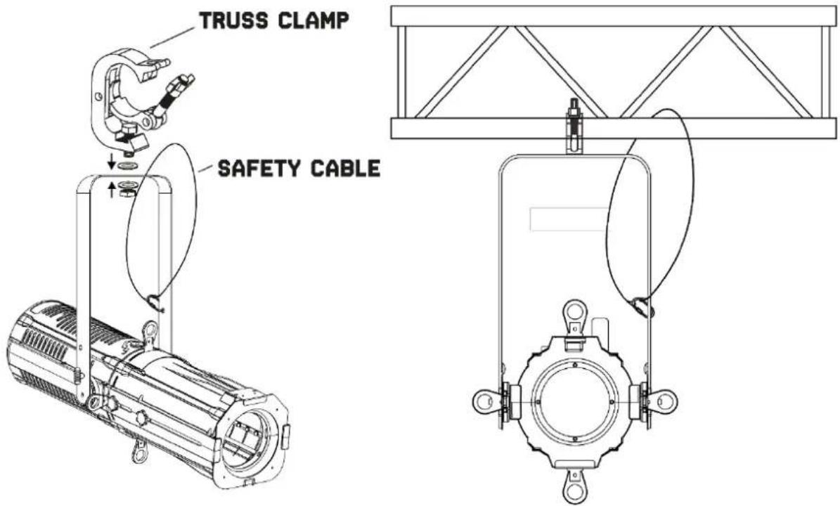
text_image
TRUSS CLAMP SAFETY CABLEDMX512 CONTROL
If you are using a standard DMX controller, you can connect the DMX output of the controller directly to the DMX input of the first fixture in a DMX chain. Always connect the output of one unit with the input of the next fixture until all fixtures are connected.
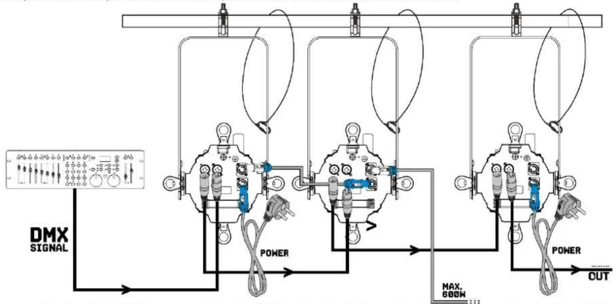
flowchart
graph TD
    A["DMX SIGNAL"] --> B["Power"]
    B --> C["OUT"]
    D["MAX. 600N"] --> E["Power"]
    E --> F["OUT"]
    style A fill:#f9f,stroke:#333
    style B fill:#ccf,stroke:#333
    style C fill:#cfc,stroke:#333
    style D fill:#fcc,stroke:#333
    style E fill:#cff,stroke:#333
    style F fill:#ffc,stroke:#333

Caution: At the last fixture, you must close the DMX line with a terminating resistor. Take an XLR connector and solder a 120 Ohm resistor between signal (-) and signal (+) and connect it to the DMX output of the last fixture in the line.
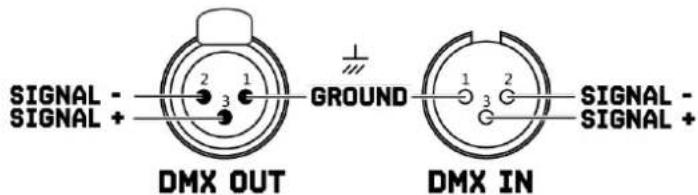
text_image
SIGNAL - SIGNAL + DMX OUT GROUND DMX IN SIGNAL - SIGNAL + Ground
text_image
1 2 3 120 OHM TERMINATORRDM CONTROL
The BTS250C can communicate using RDM (Remote Device Management) via DMX512. RDM is a bi-directional communication protocol for use in DMX512 control systems, it is the open standard for DMX512 configuration and status monitoring.
The RDM protocol allows data packets to be inserted into a DMX512 line without affecting the existing non-RDM equipment. The system allows a controller or special RDM controller to send and receive commands from specific fixtures.
The RDM function allows you, for example to remotely set the DMX start address of your fixtures. This is especially useful when the fixture is installed in an inaccessible location. Each BTS250C has an RDM UID (unique identification number).

Caution: Before using the fixture, enable the RDM function via "Advanced settings" in the menu. See below picture.
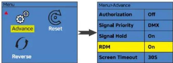
flowchart
graph LR
    A["Menu"] --> B["Advance"]
    A --> C["Reset"]
    A --> D["Reverse"]
    E["Menu>Advance"] --> F["Authorization"]
    E --> G["Signal Priority"]
    E --> H["Signal Hold"]
    E --> I["RDM"]
    E --> J["Screen Timeout"]
    E --> K["Off"]
    E --> L["DMX"]
    E --> M["On"]
    E --> N["On"]
    E --> O["30S"]
LENS TUBE
To remove and install the BTS profile lens tubes:
Step 1: Loosen (but do not remove) lens tube knobs (A).
Step2: Slide lens tube little to left or right.
Step3: Lift lens tube assembly up and away from light source.
Step4: To install perform process in reverse.
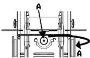
text_image
A AThe BTS profile tube has a manual zoom and focus system which allows you to easily make small focus adjustments using a gear-based knob on side of the lens tube.
- To zoom in, loosen the thumb wheel bolts (B) on the sides of the lens barrel slightly and slide lens in or out of the tube. Tighten the thumbwheel bolts again to hold the zoom setting.
- To focus in, loosen the thumb wheel bolts (C) on the sides of the lens barrel slightly and slide lens in or out of the tube. Tighten the thumbwheel bolts again to hold the zoom setting.

Caution: Ensure the lens tube locking catch is fully fixed and safety cable is attached before putting fixture into use.
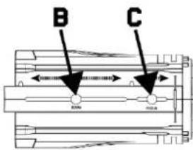
text_image
B C 300mm 400mmMANUAL SHUTTERS ADJUSTMENT
This fixture has 4 manually operated shutters for adjusting the beam.
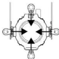
natural_image
Pure mechanical diagram showing a symmetrical cross-shaped component with mounting holes and arrows indicating direction (no text or symbols)COLOUR FILTERS
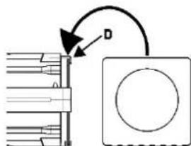
Using the colour filter frame you can add colour correction or diffusion filters to the front of the fixture. Push the securing clip (D) to one side to release it. Ensure the securing clip (D) clicked back into place to prevent the colour filter frame from falling out.
natural_image
Pure mechanical diagram showing a rotating shaft and a square component with a circular hole, without any text or symbols.
Caution: Ensure the filter holder securing clip is fully fixed and safety cable is attached before putting fixture into use.
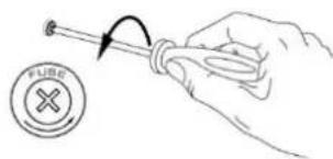
REPLACING THE FUSE
If the fuse is defective, replace the fuse with a fuse of the same type and value. Before replacing the fuse, unplug mains lead.
text_image
FUBEProcedure:
Step 1: Open the fuse holder on the rear panel with a fitting screwdriver.
Step 2: Remove the old fuse from the fuse holder.
Step 3: Install the new fuse in the fuse holder.
Step 4: Replace the fuse holder in the housing.
CLEANING
The buildup of dust, dirt and other airborne particles will reduce the fixture's light output. It will also prevent the fixture from cooling correctly, and this will reduce the fixture's lifetime. The rate of dirt buildup will vary depending on environmental factors such as airborne dust, use of smoke machines, airflow from ventilation systems, etc. The fixture's cooling fans will accelerate buildup, and any smoke particles that are present in the atmosphere will increase the tendency for dirt to clog.
To get the best performance and lifetime from the fixture, inspect it regularly and clean it as soon as you see signs of dirt buildup.
Assess the operating environment each time you begin to use the fixture. In dusty or smoky conditions, inspect the fixture after a few hours and check it frequently the fixture may attract dirt faster than you expect. Draw up a cleaning schedule that will make sure that dirt is removed before it can build up.
Use the following guidelines:
- Disconnect the fixture from power and allow it to cool completely before cleaning.
- Do not use solvents, abrasives or any other aggressive product to clean the fixture.
- Vacuum or use low-pressure compressed air to remove dust and loose particles from surfaces and air vents. Prevent the blades of cooling fans from turning before you aim a vacuum or air jet at the fan, or you may spin the fan too fast and damage it.
- Clean glass components by wiping gently with a soft, clean, lint-free cloth moistened with a weak detergent solution. Put the solution on the cloth and not on the surface to be cleaned. Avoid rubbing glass surfaces.
- Dry the fixture with a soft, clean, lint-free cloth or low-pressure compressed air before reapplying power.
TROUBLE SHOOTING
The checklist below may help you troubleshoot in the unlikely event that a problem occurs while using the product:
| Symptom | Possible cause | Suggested action |
| No light from fixture. | No power to fixture.Shutters are all pushed in and blocking the light.Fuse blown or internal fault. | Check that power is turned on.Check cables and connections.Pull out the 4 shutter blades.Replace mean fuse or contact Beamz support or Beamz authorized service partner. Do not remove base or yoke covers. Do not attempt to replace a fuse or carry out any repairs or service that are not described in this User Manual unless you have both authorization from Beamz support or Beamz authorized service partner. |
| Fixture resets correctly but does not respond (or does not respond correctly) to the controller. | The controller is not connected.Bad DMX-line.DMX-line has no end resistance.Incorrect fixture addressing.A fixture is defective and is disturbing data transmission on the DMX-line.Pin 2 and 3 are reversed in XLR connection. | Connect controller.Inspect connections and cables. Correct poor connections. Repair or replace damaged cables.Insert DMX terminator plug in DMX output socket of last fixture on DMX-line.Check fixture address and DMX mode settings.Unplug DMX IN and OUT connectors and connect them directly together to bypass one fixture at a time until normal operation is regained. Have defective fixture serviced by an authorized technician.Inspect connections and cables. Install a phase-reversing cable between the fixtures or swap pin 2 and 3 in the fixture, that behaves erratically. |
| Error after fixture reset. | Effect requires mechanical adjustment. | Check fixture's software version and error messages for more information. Contact Beamz support or Beamz authorized service partner. |
| Light output cuts out intermittently. | Fixture too hot.LEDs damagedThe power supply settings do not match local AC voltage and frequency. | Allow fixture to cool. Reduce ambient temperature. Ensure free airflow around fixture. Clean fixture if necessary.Disconnect fixture and contact Beamz support or Beamz authorized service partner.Disconnect fixture. Check settings and correct if necessary. |
VEILIGHEIDSINSTRUCTIES

text_image
B C 20mm 40mm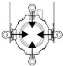
natural_image
Pure mechanical diagram showing a symmetrical cross-shaped component with four directional arrows, no text or symbols present.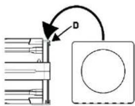
natural_image
Pure mechanical diagram showing a rotating shaft and circular component without any text or symbolsPROBLEMEN OPLOSSEN
text_image
Technical diagram showing mechanical assembly with labeled components and rotation arrowSICHERUNGWECHSEL
natural_image
Hand holding a screwdriver with a circular button labeled 'FUBE' and an arrow indicating rotation (no text or symbols on the diagram itself)Vorgehensweise:
natural_image
Pure mechanical diagram showing a symmetrical cross-shaped component with directional arrows, no text or symbols present.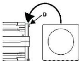
text_image
Technical diagram showing a mechanical assembly with labeled component D and directional arrowCAMBIANDO EL FUSIBLE
text_image
Diagram showing a hand holding a tool with an arrow indicating rotation, next to a circular icon with a cross symbol.Procedimiento:
natural_image
Pure mechanical diagram showing a symmetrical cross-shaped component with four directional arrows, no text or symbols present.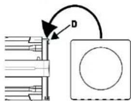
natural_image
Pure mechanical diagram showing a rotating shaft and a square component with a circular hole, no text or symbols present.REPLACEMENT DU FUSIBLE
natural_image
Pure mechanical diagram showing a symmetrical cross-shaped component with directional arrows, no text or symbols present.
text_image
Technical diagram showing a mechanical assembly with labeled component D and directional arrowWYMIANA BEZPIECZNIKA
| Menu | Description | |||
| DMX Addr | d001-d512 | DMX address setting | ||
| Mode | DMX | 1/4/6/10 Ch | DMX channel mode | |
| Auto | Program | 001-005 | Preset programs | |
| Speed | 001-009 | Programs speed | ||
| Manual | Red | 000-255 | Dimmer 0-100% | |
| Green | 000-255 | |||
| Blue | 000-255 | |||
| White | 000-255 | |||
| Strobe | 000-255 | Strobe, slow to fast | ||
| Dimmer | Curve | 0.3-3.0 | Dimmer curves adjustment | |
| Mode | Standard | Select dimmer curve | ||
| Stage | ||||
| TV | ||||
| Architecture | ||||
| Theatre | ||||
| Custom | Fade in (150ms~2230ms) | |||
| Fade out (150ms~2230ms) | ||||
| Advance | Authorization | On / Off | Advanced settings for Beamz support only. | |
| Signal priority | DMX | Signal priority setting | ||
| Signal hold | On / Off | Run if signal cut | ||
| RDM | On / Off | RDM function on / off | ||
| Screen Timeout | 30sec. | Display shut off time | ||
| Never | ||||
| Screen brightness | 10-100% | Display brightness | ||
| Reset | Yes / No | System reset | ||
| Reverse | Yes / No | Display reverse 180° | ||
DMX CHANNELS
1 Channel
| Channel | Function | Value | Description |
| 1 | Dimmer | 000-255 | Intensity 0-100% |
4 Channel
| Channel | Function | Value | Description |
| 1 | Red | 000-255 | Intensity 0-100% |
| 2 | Green | 000-255 | Intensity 0-100% |
| 3 | Blue | 000-255 | Intensity 0-100% |
| 4 | White | 000-255 | Intensity 0-100% |
6 Channel
| Channel | Function | Value | Description |
| 1 | Dimmer | 000-255 | Intensity 0-100% |
| 2 | Strobe | 000-255 | No function |
| 0005-255 | Strobe, slow to fast | ||
| 3 | Red | 000-255 | Intensity 0-100% |
| 4 | Green | 000-255 | Intensity 0-100% |
| 5 | Blue | 000-255 | Intensity 0-100% |
| 6 | White | 000-255 | Intensity 0-100% |
10 Channel
| Channel | Function | Value | Description |
| 1 | Dimmer | 000-255 | Intensity 0-100% |
| 2 | Strobe | 000-255 | No function |
| 0005-255 | Strobe, slow to fast | ||
| 3 | Red | 000-255 | Intensity 0-100% |
| 4 | Green | 000-255 | Intensity 0-100% |
| 5 | Blue | 000-255 | Intensity 0-100% |
| 6 | White | 000-255 | Intensity 0-100% |
| 7 | Colour temperature | 000-004 | No function |
| 005-040 | 2800K | ||
| 041-076 | 3089K | ||
| 077-112 | 3200K | ||
| 113-148 | 4200K | ||
| 149-184 | 5600K | ||
| 185-220 | 7600K | ||
| 221-255 | 8000K | ||
| 8 | Colour fading | 000-004 | No function |
| 005-255 | Colour fading | ||
| 9 | Colour macro | 000-004 | No function |
| 005-130 | Colour jump, slow to fast | ||
| 131-255 | Colour fading, slow to fast | ||
| 10 | Dimmer mode | 000-005 | No function |
| 006-047 | Standard mode | ||
| 048-089 | Stage mode | ||
| 090-131 | TV mode | ||
| 132-173 | Architecture mode | ||
| 174-215 | Theatre mode | ||
| 216-255 | Custom mode |
TECHNICAL SPECIFICATIONS
Rated voltage : 100-240VAC, 50-60Hz, 2.1-1.0A
LED : 250Watt
LED Colour : Red, Green, Blue, White
Colour temperature : 2800K - 8000K
Beam angle :18-36°
Illuminance : 61.077lx
Flash rate :1-19Hz
DMX channels :1,4,6 and 10
Function : DMX, RDM and manual
Dimensions per unit : 745 x 294 x 294mm
Weight (per unit) : 9.1 kg
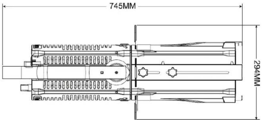
text_image
745MM 294MM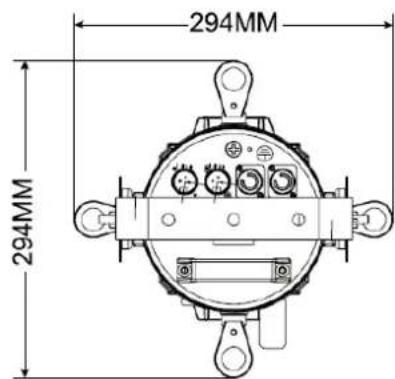
text_image
294MM 294MMDesign and product specifications are subject to change without prior notice.
European Union
Tronios B.V..
7602KR Almelo, The Netherlands
2014/35/EU
2014/30/EU
2011/65/EC

United Kingdom
Tronios Ltd.,
130 Harley Street,
London W1G 7JU, United Kingdom
S.I. 2016:1101
S.I. 2016:1091
S.I. 2012:3032

BEAMZ
offers a wide range of high performance lighting equipment and related accessories for the rental, entertainment and architectural lighting markets. BeamZ Pro stands for performance, innovation and value pricing!


