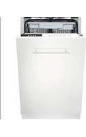
DWVFI18 - Dishwasher Porter & Charles - Free user manual and instructions
Find the device manual for free DWVFI18 Porter & Charles in PDF.


| Product Type | Dishwasher |
| Brand | Porter & Charles |
| Model | DWVFI18 |
| Capacity | 10 place settings |
| Dimensions (W x D x H) | 450 mm x 570 mm x 824-874 mm (adjustable height) |
| Weight | Approximately 40 kg |
| Electrical Supply | 120 V, 60 Hz, 12 A, dedicated 15 A circuit |
| Total Power | 1400 W |
| Heating Power | 1100 W |
| Water Pressure Range | 43.5 - 145 psi (0.3 - 10 bars) |
| Installation Type | Built-in (fully integrated) |
| Adjustable Height | Yes, via front and rear feet |
| Water Connection | Hot water, braided hose or 3/4 in copper pipe |
| Drain Hose | Minimum height of 28 in (710 mm) |
| Vapor Protection | Protection sheet provided to install under countertop |
| Cabinet Mounting | Mounting brackets provided |
| Custom Door | Compatible, max weight 7 kg |
| Warranty | 2 years from date of purchase |
| After-Sales Service | Call 1-866-699-4973 (Canada) |
Frequently Asked Questions - DWVFI18 Porter & Charles
User questions about DWVFI18 Porter & Charles
0 question about this device. Answer the ones you know or ask your own.
Ask a new question about this device
Download the instructions for your Dishwasher in PDF format for free! Find your manual DWVFI18 - Porter & Charles and take your electronic device back in hand. On this page are published all the documents necessary for the use of your device. DWVFI18 by Porter & Charles.
USER MANUAL DWVFI18 Porter & Charles
Top Control Fully Integrated 18"

natural_image
Illustration of green bamboo stalks with leaves, no text or symbols presentTo prevent accidents, which could cause serious injury or death, as well as machine damage read these instructions before installation and / or use.
Contents
1. IMPORTANT SAFETY INSTRUCTIONS 1
2. TOOLS WHICH MAY BE NEEDED 4
3. MATERIALS WHICH MAY BE NEEDED 4
4. MATERIALS SUPPLIED 5
4.1 PARTS SUPPLIED 5
4.2 MANUAL BAG 5
4.3 DISHWASHER PARTS BAG 1 5
4.4 DISHWASHER PARTS BAG 2 5
4.5 DISHWASHER PARTS BAG 3 5
4.6 DISHWASHER PARTS BAG 4 5
4.7 DISHWASHER PARTS BAG 5 5
5. DISHWASHER SPECIFICATIONS 6
5.1 TECHNICAL FEATURES 6
6. ENCLOSURE PREPARATION 7
6.1 ELECTRICAL PREPARATION 7
6.2 PREPARATION FOR INSTALLING MOUNTING BRACKETS 7
6.3 ADJUSTING HEIGHT 8
6.4 PREPARING THE WATER CONNECTION 9
6.5 STEAM PROTECTION FOIL 10
7. PLACEMENT OF DISHWASHER INTO THE OPENING 11
7.1 DRAIN HOSE CONNECTION, WATER SUPPLY & ELECTRICAL CONNECTIONS 11
7.2 ADJUSTING THE MOVABLE TOE KICK 14
7.3 INSTALLING THE OUTER DOOR 15
8. INSTALLER CHECKLIST 18
9. FINAL INSTRUCTIONS 18
10. SELF HELP HINTS: 18
INTRODUCTION
When using the dishwasher, carefully follow precautions in this instruction manual, especially the safety instructions. These are provided in order to save you, your time and effort and help to ensure optimum dishwasher performance. Be sure to observe all listed warnings and cautions. Look particularly for the icons with exclamation marks inside. The information icon will also provide important references.
WARNING:
Indicates a potentially hazardous situation which, if not avoided, could result in death or serious injury.
CAUTION:
Indicates a potentially hazardous situation which, if not avoided, may result in injury. It may also be used to alert against unsafe practices.
Notice:
Indicates a potentially hazardous situation which, if not avoided, may result in damage to the dishwasher, the table-ware, the equipment or the environment.
1. IMPORTANT SAFETY INSTRUCTIONS
In addition to these instructions, the dishwasher shall be installed:
* In accordance with all local codes or, in absence of a local code,
* In the United States, with the National Electric Code,
* In Canada, with the Canadian Electric Code C22.1-latest edition/Provincial and Municipal codes and/or local codes.
i Notice
Read these installation instructions completely before installing and follow them carefully. Save these installation instructions and pass them on to any future user.
WARNING
When installing the dishwasher, follow basic precautions, including the following:
- The dishwasher could only be converted from cord-connected to permanently connected by an authorized service representative. (If needed contact your dealer to schedule an authorized service agent for conversion with an appropriate conversion kit)
• Installation and repair should be performed by a qualified installer. Work by unqualified persons could be dangerous and may void the warranty.
Notice
The dishwasher should be installed by an insured licensed plumber, contractor or trained installer. Installation performed by persons other than this could result in improper installation and property damage.
- Do not operate the appliance if damaged, malfunctioning, partially disassembled or if it has missing or broken parts.
- Also follow the safety instructions of the user manual.
• To reduce the risk of electric shock, fire, or injury to persons, the installer must ensure that the dishwasher is completely enclosed at the time of installation. - Only connect the dishwasher to the power supply when all installation and plumbing work is complete
- If the dishwasher is installed in a location that experiences freezing temperatures (e.g. in a vacation home, cabin, etc.), you must drain all the water from the dishwasher's interior. Water system ruptures that occur as a result of freezing are not covered by warranty
- Dishwasher must be secured to adjacent cabinetry using the brackets provided. Failure to do this may cause damage to property or bodily injury
Connect to a properly rated, protected and sized power supply circuit to avoid electrical overload. The dishwasher is designed for an electrical supply of 120 V (volts), 60 Hz (hertz), AC, connected to a dishwasher-dedicated, properly grounded electrical circuit with a fuse or breakers rated for 15 amperes. Electrical supply conductors shall be a minimum of # 16 AWG copper wire rated at 75 °C (167 °F) or higher. These requirements must be met to prevent injury and machine damage. Consult a qualified electrician if in doubt.
- Do not use any extension cord or portable outlet device to connect the dishwasher to a power supply.
-
Ensure that any plastic wrappings, bags, small pieces etc. are disposed of safely and kept out of the reach of children. Danger of suffocation!
-
Remove the door to the washing compartment when removing an old dishwasher from service or discarding it. Ensure that the appliance presents no danger to children while being stored for disposal.
- Old appliances may contain materials that can be recycled. Please contact your local recycling authority about the possibility of recycling these materials.
Notice
- The dishwasher drain hose must be installed with a drain loop at least 28" (710mm) off the cabinet floor; otherwise the dishwasher may not drain properly.
- This dishwasher is intended for residential use only, and should not be used in commercial establishments.
- New installation - If the dishwasher is a new installation, most of the work must be done before the dishwasher is moved into place.
- Replacement - If the dishwasher is replacing another dishwasher, check the existing dishwasher connections for compatibility with the new dishwasher, and replace parts as necessary.
2. TOOLS WHICH MAY BE NEEDED
natural_image
Yellow and black wrench tool with adjustable handle (no text or symbols)Pipe Wrench
natural_image
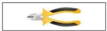
Pliers with yellow and black handles (no text or symbols visible)Wire Cutter

natural_image
Yellow electric drill bit with trigger, isolated on white background (no text or symbols)Drill
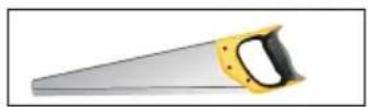
Hole Saw
natural_image
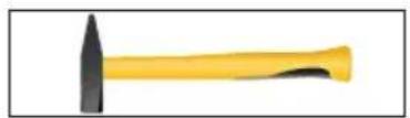
Yellow and black tool with a hammerhead, isolated on white background (no text or symbols)Hammer
natural_image
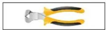
Close-up of a pair of yellow-handled pliers with metallic handles (no text or symbols visible)Wire Stripper
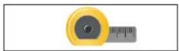
Tape Measure
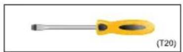
natural_image
Yellow screwdriver with a black handle, labeled (T20) in the corner (no other text or symbols)Torx Screwdriver
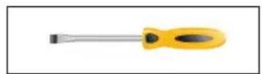
natural_image
Yellow screwdriver with black head and metallic shaft (no text or symbols)Phillips Screwdriver
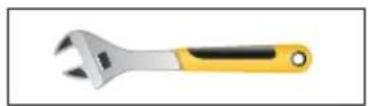
Adjustable Wrench
natural_image
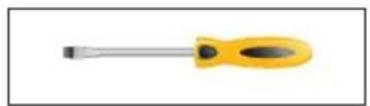
Yellow screwdriver with black head and metallic shaft (no text or symbols)Slot Screwdriver
natural_image
Illustration of a pair of scissors with gold blades (no text or symbols)Scissors
natural_image
Yellow horizontal scale with three green circular markers at the ends (no text or symbols)Level
natural_image
Yellow paintbrush with black bristles on a plain white background (no text or symbols)Brush
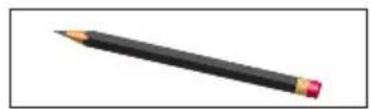
natural_image
Black pencil with eraser on white background (no text or symbols)Pencil
3. MATERIALS WHICH MAY BE NEEDED
(Additional materials may be required to comply with local codes)
Hot Water Supply Line - Minimum 3/4" O.D. copper tubing or metal braided dishwasher supply line.
UL listed conduit connector or strain relief.
Teflon tape or other pipe thread compound to seal plumbing connections.
Shut-off valve and fittings appropriate for hot water supply line (copper tubing/compression fitting, or braided hose).
Silicone
Glue
4. MATERIALS SUPPLIED
4.1 PARTS SUPPLIED
a.

b.
C.

d.

e.

f.

g.

h.

j.

k.
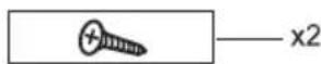
L

m.

n.
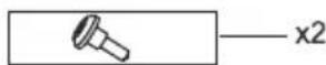
o.
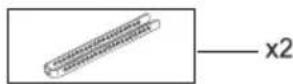
p.
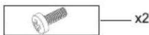
r.
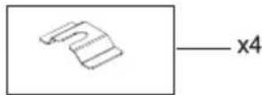
s.
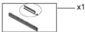
t
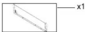
v.
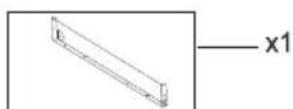
y.
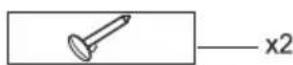
Z.
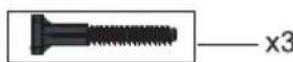
The parts required for positioning the dishwasher are in plastic bags. Check that all of the following parts are contained in plastic bags.
4.2 MANUAL BAG
The dishwasher comes with a manual bag containing: User manual, Installation manual and
4.3 DISHWASHER PARTS BAG 1
This dishwasher bag comes with the following parts:
a. Test Strip (model depending)
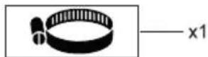
b. Hose Clamp
4.4 DISHWASHER PARTS BAG 2
Mounted planc.
d. Steam Protection Foil
e. Side Trim Strips (Left)
f. Side Trim Strips (Right)
g. Wooden Door Fixing Strips
h. Hole Covers
4.5 DISHWASHER PARTS BAG 3
j. Screws ∅ 5/32" x 53/32" (∅ 4mm x 42,5mm)
k. Screws ∅ 5/32" x 19/32" (∅ 4mm x 15mm)
I. Mounting Bracket Left
mMounting Bracket Right
n.Screws ∅ 5/32" x 27/32" (∅ 4mm x 21,5mm)
4.6 DISHWASHER PARTS BAG 4
(MODEL DEPENDING)
o. Toe Kick Bracket
p. Screws ∅ 5/32" x 7/32" (∅ 4mm x 6mm)
r. Plinth Fixing Metal
s.Adjustable Plinth
t. Adjustable Plinth Metal (130mm) (model depending)
v.Adjustable Plinth Metal (80mm) (model depending)
y. Plinth Locking
4.7 DISHWASHER PARTS BAG 5
(MODEL DEPENDING)
z. Long Legs
5. DISHWASHER SPECIFICATIONS
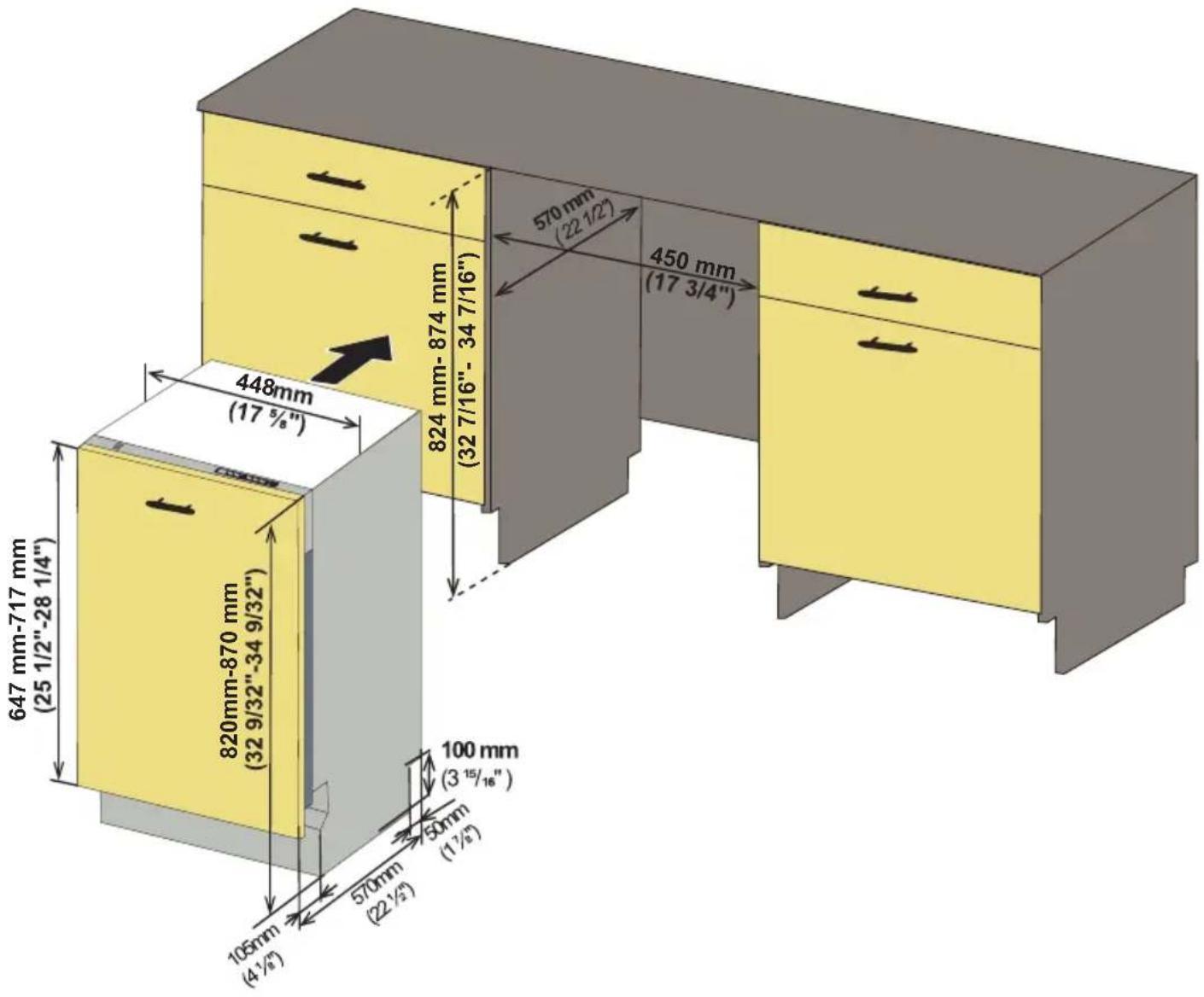
5.1 TECHNICAL FEATURES
| Load capacity 10 place settings | |
| Permissible water pressure 43.5 - 145 psi (0.3 - 10 bars) | |
| Electrical connection | 120 V (volts), 12 A (amps), 60Hz (hertz) |
| Total power 1400 W (watts) | |
| Heater power 1100 W (watts) | |
Notice :
Because we continually strive to improve our products, we may change our specifications and design without prior notice.
This device corresponds to the following directives:
UL 749 Household Dishwasher directive.
6. ENCLOSURE PREPARATION
6.1 ELECTRICAL PREPARATION
WARNING
The dishwasher is designed for an electrical supply of 120 V, 60 Hz, AC, connected to a dishwasher-dedicated, properly grounded electrical circuit with a fuse or breaker rated for 15 amperes.
6.2 PREPARATION FOR INSTALLING MOUNTING BRACKETS

WARNING
The mounting brackets in the plastic bag should be used when the dishwasher is installed in the cabinetry. Use of any parts other than mounting brackets may result in damage to property or bodily injury.

Notice
There shall be an opening through the partition between the compartments that is large enough for the attachment plug to pass through. the longest dimension of the opening shall not be more than 38.1 mm (1.5 inch)
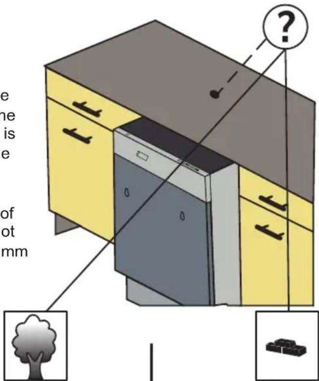

Notice
The edges of the cabinetry, if the partition is wood, be smooth and rounded, or, if the partition is metal, be covered with an edge protector and care shall be exercised, when the appliance is installed or removed, to reduce the likelihood of damage to the power supply cord.

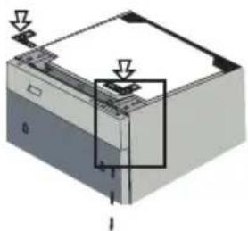
If material of countertop board is wooden etc.;
natural_image
3D diagram of a mechanical or electronic component with arrows indicating direction (no text or symbols)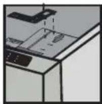
natural_image
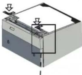
Pure technical diagram of a mechanical assembly without any text, numbers, or symbolsIf material of countertop board is ceramic etc.;
natural_image
3D diagram of a mechanical or electronic component with arrows indicating direction (no text or symbols)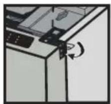
natural_image
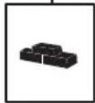
Diagram of a kitchen appliance with a door handle and a scroll wheel (no text or symbols)Place the two mounting brackets into the top corners of the dishwasher.
If necessary (according to counter top board material), bend sides of mounting brackets.
6.3 ADJUSTING HEIGHT
CAUTION
First Step: Before the dishwasher is placed in the cabinetry, the front feet are closed until the end and the dishwasher is placed in the cabinetry.
Second Step: Adjust the forefoot level with a slot screwdriver to stabilize the dishwasher and raise it to the enclosure height.
Third Step: Adjust the rear foot level with a philips screwdriver to balance and raise the dishwasher to the enclosure height.
Notice
- Make sure the dishwasher is level and notice dishwasher can be placed with a small clearance under the counter top.
-For front feet; turning the feet in the direction of the black arrows with the slot screwdriver allows the dishwasher to move downwards.
-For rear feet; Turning the philips screwdriver in the direction of the black arrows will take the dishwasher feet down.
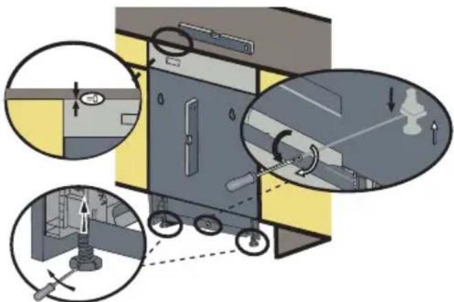
If the height of the enclosure is 32 9/32" to 34 9/32" (820mm-870mm) use short supports as shown in the figure.
ops.(+50) H= 32 9/32" - 34 9/32" (820mm-870mm)
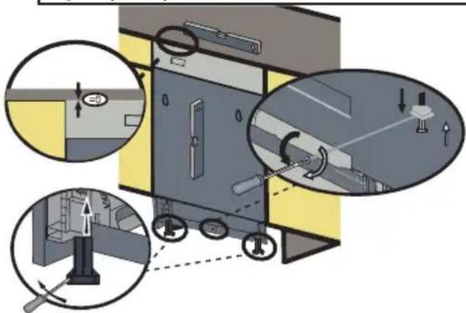
If the height of the enclosure is above 34 9/32" (870mm) use long supports as shown in the figure.
6.4 WATER SUPPLY CONNECTION
Water supply may be connected to the dishwasher in one of two ways:
- With metal braided hose.
- With copper tubing
BRAIDED HOSE/COPPER TUBING
After connections are made turn on the water supply to check for leaks.

CAUTION
Cold water supply line: Use minimum 3/4" O.D. copper tubing or metal braided dishwasher supply line.
Water Inlet valve of dishwasher has 3/4"-11.5NH inlet coupling thread dimension according to ASME B1.20.7-1991.
When buying water inlet hose for your dishwasher, please choose the thread dimension of the inlet hose as compatible with indicated water inlet valve inlet coupling thread dimension (3/4"-11.5NH) of your dishwasher.
- Temperatures required for soldering and sweating will damage the dishwasher's water inlet valve so if any such operation is needed, keep the heat source min. 77/8" (200mm) away from the dishwasher's water inlet valve.
- There should not be any sharp bends in the water line that may restrict the water flow.
- Teflon tape or pipe tread compound must be used for sealing the connection. Before connecting the copper water supply line to the dishwasher, flush it with hot water to clear any foreign material.
natural_image
Pure electrical circuit lines without any symbols6.5 STEAM PROTECTION FOIL
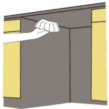
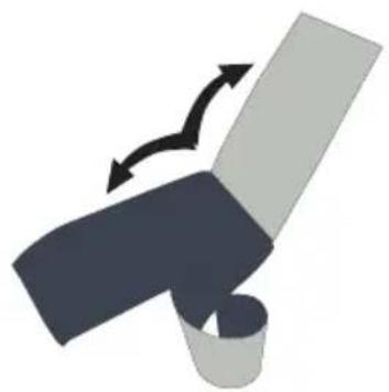
Steam will be output when the dishwasher door is opened during the operation of the dishwasher and after completion of the working cycle. In order to prevent the resulting steam from collecting and damaging at the underside of the counter top, use a steam protection foil included in the plastic bag.
natural_image
Illustration of a hand cleaning a cabinet with yellow panels (no text or symbols)6.5.1 FITTING THE PROTECTION FOIL
Clean the surface with a damp cloth before applying steam protection to the underside of the counter top.
natural_image
Diagram showing a mechanical or robotic arm with directional arrows indicating motion (no text or symbols)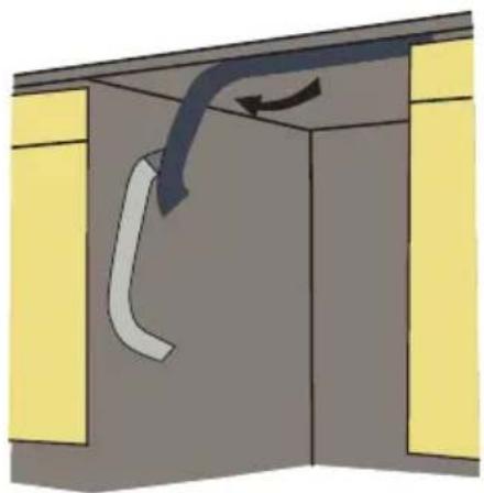
natural_image
Diagram of a cabinet interior with a curved duct and airflow direction arrow (no text or symbols)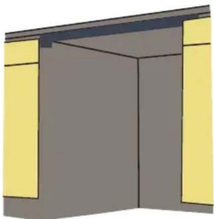
natural_image
Simple 3D illustration of a room with yellow walls and a central doorway (no text or symbols)CAUTION
Steam protection foil must be applied where the steam escapes when door is first opened. Failure to install the steam protection foil during installation can lead to damage to the cabinets and countertop.
7. PLACEMENT OF DISHWASHER INTO THE OPENING
Now place the dishwasher into the opening and get ready to connect all hoses and electrical connections.
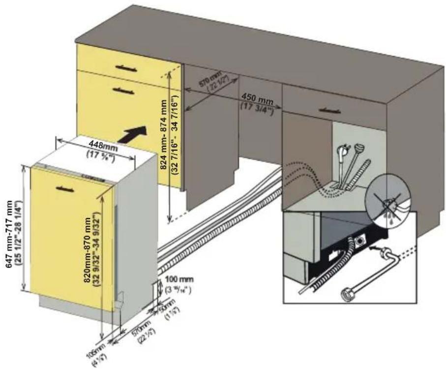

CAUTION
Make sure all hoses are pulled through the side opening of the cabinet, no hoses are kinked and all slack is taken out as shown in the figure.
7.1 DRAIN HOSE CONNECTION, WATER SUPPLY & ELECTRICAL CONNECTIONS
7.1.1 DRAIN HOSE CONNECTION
- Check the parts on the sink to which the drain hose will be connected.
- There are several ways to insert the drain hose into the drain hose connector of the sink, as shown in the following figures. You must connect the drain hose in accordance with the water pipe installation regulations in your region.
| Garbage disposal With an air gap Without an air gap | ||
| Air gap Hose clamp Drain hose Hose clamp | ||
A. Without disposal
| Garbage disposal With an air gap Without an air gap | ||
| Air gap Hose clamp Drain hose Hose clamp | ||
B. With disposal
- Check the size of the sink's drain hose connector. If needed, cut the drain hose so it's end fits onto the sink connector (5/8 in., 3/4 in. or 1 in. - as shown in C below). If the end of the drain hose does not fit onto the drain hose connector of the sink, use an adaptor purchasable at a plumbing/hardware supply store.
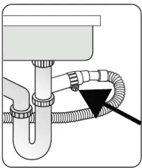
- Slide a hose clamp over the end of the drain hose. Attach the drain hose to the sink connector, slide the hose clamp to the end of the hose, and then tighten the hose clamp. Note: You must use a hose clamp. Failure to do so may cause water leakage.
- If there is no air gap, make sure to hang. the middle of the drain hose well above the sink cabinet base to prevent back flow (see Figure E below).
- When drilling a hole for the drain hose on the cabinet wall, take caution not to damage the drain hose by sharp edges of the hole. On wooden walls, use sanding to soften the edges. On metal walls, use insulation tape or duct tape to cover the sharp edges around the hole.
- Take caution not to damage the drain hose when installing the dishwasher on the floor, wall, or cabinet.
To prevent leaks or drainage problems, make sure the drain hose is not damaged, kinked, or twisted.
-
Do not cut the wrinkled area of the drain hose to fit the size. When arranging the drain hose, take caution not to contact on sharp edges of the cabinet or under-sink.
-
Be careful when cutting off the end of the drain hose as there is a risk of injury.
Clean around the sink's drain connection so that it does not damage the hose. Check for any foreign items in the drain hose and remove them. - When arranging the drain hose, make sure the drain hose is not cut, torn, or broken by any sharp edges of the floor, the product itself, or the cabinet. A damaged drain hose causes a leak.
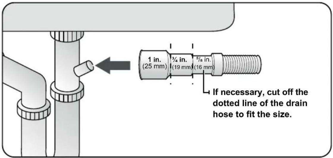
C
natural_image
Diagram of a plumbing sink with coiled tubing and a black arrow indicating a component (no text or symbols)Use hose clamp shown in Figure 4. for drain hose assembly to the sink.
D
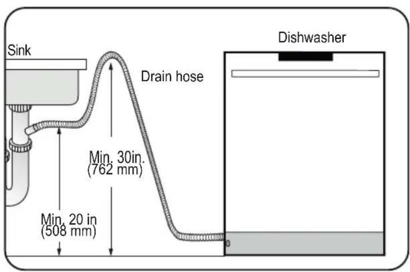
E
7.2 ADJUSTING THE MOVABLE TOE KICK (MODEL DEPENDING)
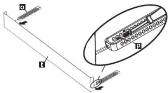
Now that you have successfully installed the dishwasher, you need to attach the toe kick to the dishwasher. The two piece toe kick can be adjusted to the height and depth needed for your kitchen. 1. A. If the height is 32.9/32" to 34.9/32"
-
A. If the height is 32 9/32" to 34 9/32" (820mm-870mm) and use short supports; adjustable plinth metal with 80 mm length (v), toe kick brackets(o) are installed. Mounting is done using Screws ∅ 5/32" x 7/32" (∅ 4mm x 6mm) with a Philips Screwdriver. B. A. If the height is above 34 9/32" (870mm) and use short supports; adjustable plinth metal with 130 mm length (v), toe kick brackets(o) are installed. Mounting is done using Screws ∅ 5/32" x 7/32" (∅ 4mm x 6mm) with a Philips Screwdriver.
-
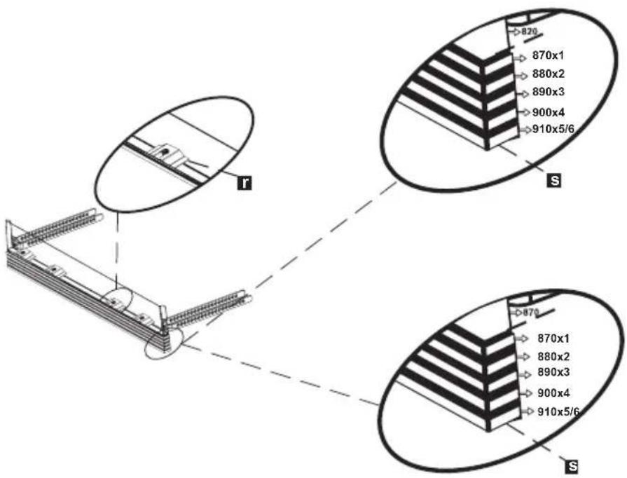
The adjustable plinth number is determined according to the required distance and assembled to each other.
- As shown in the Figure, the cylindrical feet of the adjustable plinth are attached to the plinth fixing metal parts and shifted through the cavity of the part.
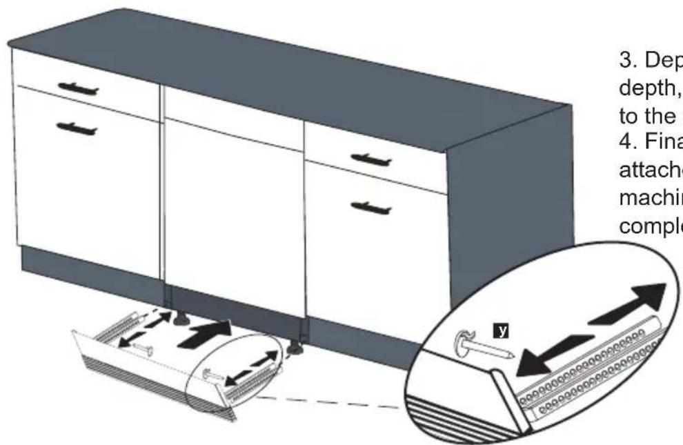
- Depending on the desired depth, plinth locking(y) is attached to the toe kick bracket(o).
- Finally, Toe kick brackets(o) are attached to the gaps under the machine and the installation is completed.
7.5 INSTALLING THE OUTER DOOR (MODEL DEPENDING)
As shown in Figure A, you must measure the height and depth of the cabinetry to determine the dimensions of the outer door.
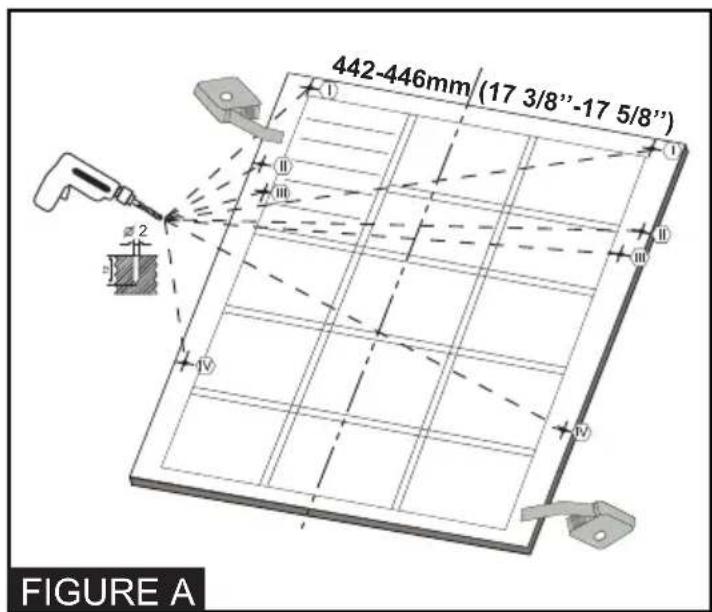
- The mounting plan in the plastic bag is fixed to the inside of the Dishwasher door.
While fixing the mounting plan, ensure that the plan is adhered to the inside of the door. When the fastening is complete, the mounted plan must remain straight on the outer door.
- As shown in Figure A, the screw hole is opened to the outer door from the points marked on the mounted plan. Diameter of Drilling Bit: 5/64" (2 mm) Depth of Drilling Bit: 15/32" (12 mm)
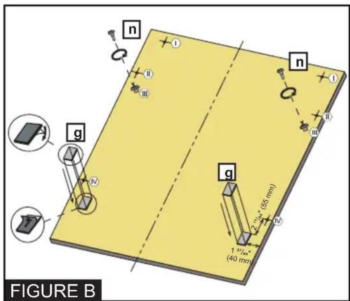
3- As shown in Figure B, Screws ∅ 5/32" x 27/32" (∅ 4mm x 21,5mm) is installed in positions III.
4- As shown in Figure B, Wooden Door Fixing Strips are installed in positions shown in the figure.
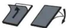
Before attaching Wooden Door Fixing Strips, white papers on both sides are taken from the surface.
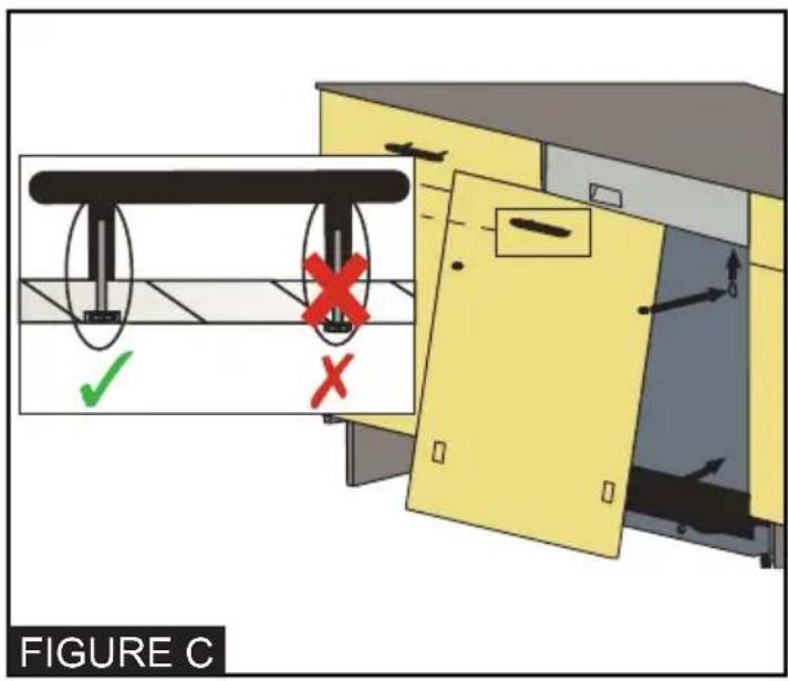
5- Before mounting the wooden door on the dishwasher, mount the handle on the wooden door as in figure C.
6- The screws located on the wooden door are fitted with the dishwasher corresponding to the discharges located on the door outer sheet and are assembled as shown in Figure D.
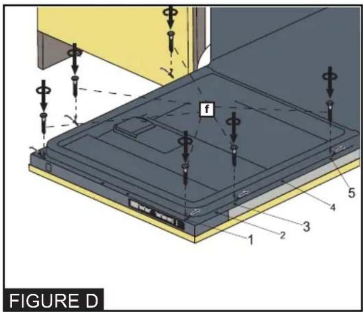
7- As shown in Figure D, Screws ∅ 5/32" x 53/32" (∅ 4mm x 42,5mm) are installed in positions I,III and V.
Notice
Before mounting the Screws ∅ 5/32" x 53/32" (∅ 4mm x 42,5mm); Screws in positions I,III and V must be removed.
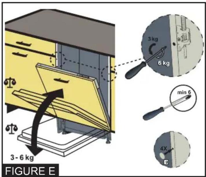
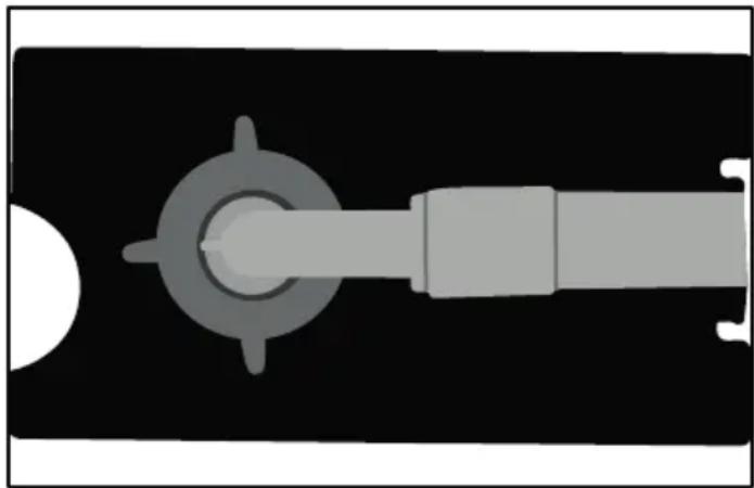
8- According to the weight of the assembled wooden door, the balancing must be provided by the mechanism shown in Figure E. - If the wooden door is falling down, the mechanism must be turned in the direction of the white arrow with a philips screwdriver. - If the wooden door is lifted upwards, the mechanism must be turned in the direction of the black arrow with a philips screwdriver.
i Notice
Minimum Philips Screwdriver Diameter is 15/64" (6 mm) for this application.
9- After providing the door balance, hole covers are glued to the empty holes and the holes are closed.
Notice
Maximum weight of custom panel must not exceed 7 kg.
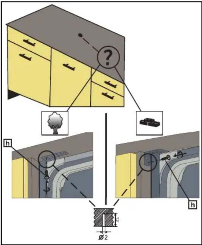
10- Mounting brackets previously fixed to the dishwasher are also fixed in the cabinetry with Screws ∅ 5/32" x 19/32" (∅ 4mm x 15mm).
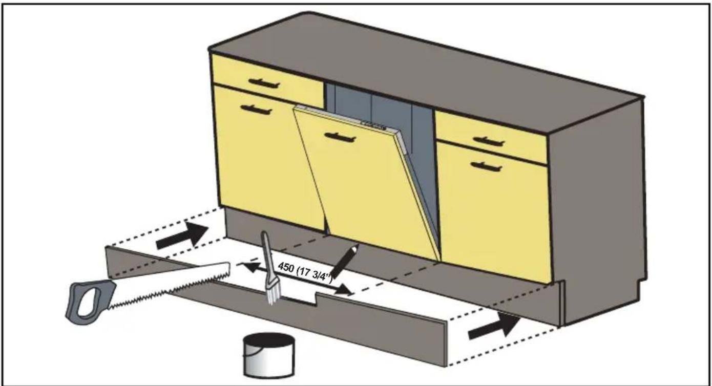
- Check whether the bottom of the door hits the toe kick of the kitchen cabinet.
- If the door hits the toe kick cut the necessary section out of the toe kick.
- Apply silicon or sealant to the cut edge of the kitchen cabinet toe kick or paint so it does not absorb moisture.
8. INSTALLER CHECKLIST
Your installer must have completed and checked the following:
- The dishwasher is square and level.
- The dishwasher is fastened securely to the cabinetry.
- The dishwasher door opens and closes freely. The dishwasher door must close without hitting any cabinetry or counter top.
- The inlet water supply is turned on and checked for leaks.
- The drain hose has been connected and checked for leaks. There must be no kinks or obstructions in the drain hose.
- The drain hose must be installed with a 28" (710mm) high drain loop for drain hook-ups without any air removed.
- If you connect the water drain hose to a trap spigot under the sink, remove the plastic membrane. If you do not remove the entire membrane, remaining food can cause a blockage in the drain hose spigot. Ensure a hose clamp is used to secure the hose to the spigot.
- The spray arms are free and rotate freely.
- The rinse cycle has been run.
- The water level will be below the filter screen after the end of the wash program. It is normal to find some water in the drain filter area.
9. FINAL INSTRUCTIONS
- Press the On/Off button to turn the dishwasher on.
- Power indicator light comes on.
- Use the Program Select button to choose a washing program.
- Start the program with the Start/Pause/Cancel button.
- Run the dishwasher through one complete cycle. When the wash cycle is completed, use the On/Off button to turn the dishwasher off.
Notice :
If the dishwasher does not operate properly, refer to the self help hints.
10. SELF HELP HINTS:
The screen does not come on:
- Check to make sure the breaker to the dishwasher is in the on position.
- Check to make sure that the Supply cord is plugged in.
No Water is coming into the dishwasher:
- Check to make sure the water shut-off is in the ON position.
Water does not drain:
- Make sure drain hose is not kinked or comes out of air gap next to the sink.
- Remove drain hose from disposal making sure plug is removed.
Notice :
- If your dishwasher is not operating properly after following these steps: Contact your dealer to schedule an authorized service agent to inspect your new dishwasher for any function related failure.
- The manufacturer warranty does not cover installation, conversion or customer education service visits.

You will find the model and serial number information on the label located on the right-hand side of the inner door of your dishwasher, as shown above.
Notice :
Please make a copy of your invoice and keep it with this manual and register your dishwasher on-line.
Porter&Charles products are designed and built to the highest standards.
We expect your appliances to provide many years of trouble free enjoyment. In the event of an appliance requiring attention, each appliance is covered by a 2 year warranty from the date of purchase.
Refer to warranty policy for complete terms and conditions.
Coverage is for costs of parts and labour for appliances in capital cities & metropolitan areas. We reserve the right to charge directly for handling expenses outside the metropolitan region.
Porter&Charles products are supported by a national service support system.
Call our customer service department for attention.
Please retain your invoice to quote should you require service assistance. This will identify your product for our priority service back-up. Please attach your invoice to this manual for easy future reference. To register your purchase, you can either complete the section below to mail or fax, or register online at www.porterandcharles.ca/pc-warranty/

871 Cranberry Court
Oakville, ON L6L 6J7
Canada.
Toll: 1-866-699-4973
Tel: 905-829-8389
Fax: 905-829-8409
Email: info@ela.ca
For Service & Parts:
EURO-PARTS
1-866-722-2262
-cut along line
Important: Please record details of your purchase below and mail or e-mail to Porter&Charles
Name: ____ Tel No ____
Address:
City : ____ Prov/State: ____ Postal Code/ZIP: ____
Where purchased: ____ Purchase date: ____
Items purchased:
Serial No's: :

natural_image
Illustration of green bamboo stalks with leaves, no text or symbols presentLave-vaisselle
natural_image
Illustration of green bamboo stalks with leaves, no text or symbols present
AVERTISSEMENT :
natural_image
Illustration of a kitchen appliance with a large oven and a question mark, no text or symbols presentnatural_image
3D diagram of a mechanical assembly with mounting holes and internal components (no text or symbols)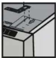
natural_image
Diagram of a printer or printer with a paper plane and a ruler, showing no text or symbols.natural_image
3D diagram of a mechanical assembly with arrows indicating force or movement (no text or symbols)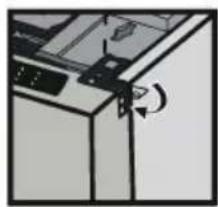
natural_image
Diagram of a mechanical device with a rotating arrow indicating rotation (no text or symbols)
nstructions
natural_image
Pure electrical circuit lines without any symbolsnatural_image
Illustration of a hand cleaning a cabinet with green walls and yellow panels (no text or symbols)6.5.1 MONTAGE DE LA FEUILLE DE PROTECTION
natural_image
Illustration of a mechanical or robotic arm with directional arrows indicating motion (no text or symbols)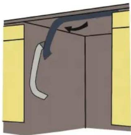
natural_image
Diagram of a cabinet interior with yellow doors and a curved pipe, no text or symbols present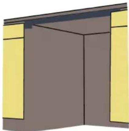
natural_image
Simple 3D illustration of a room with green walls and yellow doors, no text or symbols presentATTENTION
natural_image
Diagram of a plumbing sink with tubing and a black arrow indicating a cable or component (no text or symbols)natural_image
Illustration of a cabinet with drawers and a door, showing airflow direction (no text or symbols)natural_image
Illustration of green bamboo stalks with leaves, no text or symbols present

- Contents
- IMPORTANT SAFETY INSTRUCTIONS 1
- TOOLS WHICH MAY BE NEEDED 4
- MATERIALS WHICH MAY BE NEEDED 4
- MATERIALS SUPPLIED 5
- DISHWASHER SPECIFICATIONS 6
- TECHNICAL FEATURES 6
- ENCLOSURE PREPARATION 7
- PLACEMENT OF DISHWASHER INTO THE OPENING 11
- INSTALLER CHECKLIST 18
- FINAL INSTRUCTIONS 18
- SELF HELP HINTS: 18
- INTRODUCTION
- WARNING:
- CAUTION:
- Notice:
- IMPORTANT SAFETY INSTRUCTIONS
- i Notice
- WARNING
- Notice
- TOOLS WHICH MAY BE NEEDED
- MATERIALS WHICH MAY BE NEEDED
- MATERIALS SUPPLIED
- PARTS SUPPLIED
- MANUAL BAG
- DISHWASHER PARTS BAG 1
- DISHWASHER PARTS BAG 2
- DISHWASHER PARTS BAG 3
- DISHWASHER PARTS BAG 4
- DISHWASHER PARTS BAG 5
- DISHWASHER SPECIFICATIONS
- TECHNICAL FEATURES
- Notice :
- ENCLOSURE PREPARATION
- ELECTRICAL PREPARATION
- PREPARATION FOR INSTALLING MOUNTING BRACKETS
- ADJUSTING HEIGHT
- CAUTION
- WATER SUPPLY CONNECTION
- BRAIDED HOSE/COPPER TUBING
- STEAM PROTECTION FOIL
- FITTING THE PROTECTION FOIL
- PLACEMENT OF DISHWASHER INTO THE OPENING
- DRAIN HOSE CONNECTION, WATER SUPPLY & ELECTRICAL CONNECTIONS
- DRAIN HOSE CONNECTION
- ADJUSTING THE MOVABLE TOE KICK (MODEL DEPENDING)
- INSTALLING THE OUTER DOOR (MODEL DEPENDING)
- INSTALLER CHECKLIST
- FINAL INSTRUCTIONS
- SELF HELP HINTS:
- Lave-vaisselle
- AVERTISSEMENT :
- MONTAGE DE LA FEUILLE DE PROTECTION
- ATTENTION
Brand : Porter & Charles
Model : DWVFI18
Category : Dishwasher