RUBIN 1 - Garden greenhouse EINHELL - Free user manual and instructions
Find the device manual for free RUBIN 1 EINHELL in PDF.

| Product type | Aluminum garden greenhouse with ribbed panels |
| Brand | Einhell |
| Model | RUBIN 1 |
| Number of panels available | 3, 4, 5, 6 or 7 panels |
| Dimensions (depending on model) | Overall length: 224 cm (3 panels) to 508 cm (7 panels); Width: 259 cm for all; Estimated height: approximately 2 m |
| Estimated weight | Approximately 100 to 150 kg depending on size |
| Main material | Anodized aluminum profiles, ribbed polycarbonate panels |
| Door type | Single or double depending on configuration |
| Windows | Provided on the roof (specific frames) |
| Foundation required | Yes, in concrete/masonry or steel (option) |
| Electrical supply | None (passive greenhouse, no integrated lighting or heating) |
| Main functions | Plant protection from weather, creation of a microclimate for sheltered cultivation |
| Maintenance and cleaning | Check and tighten screws every 3 months; clean panels with a soft cloth; remove snow from roof in winter |
| Safety | Two-person assembly recommended; wear gloves when handling aluminum; do not use fire inside; storm anchoring advised in windy areas |
| Spare parts and repairability | Spare parts available (references provided in manual); steel foundation available as accessory |
| Warranty | 2 years against manufacturing defects |
| General information | Multilingual manual available online; modular assembly; domestic use |
Frequently Asked Questions - RUBIN 1 EINHELL
User questions about RUBIN 1 EINHELL
0 question about this device. Answer the ones you know or ask your own.
Ask a new question about this device
Download the instructions for your Garden greenhouse in PDF format for free! Find your manual RUBIN 1 - EINHELL and take your electronic device back in hand. On this page are published all the documents necessary for the use of your device. RUBIN 1 by EINHELL.
USER MANUAL RUBIN 1 EINHELL
natural_image
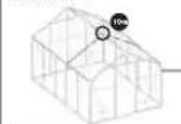
Isometric wireframe structure of a two-story building frame (no text or symbols)Illustration: Greenhouse with 5 panels / Figure: Serre à 5 pans / Afbeelding: serre met 5 velden Bild: Växthus med fem fält / Figura: serra a 5 pannelli / Obrázek: Skleník 5 polí / Obrázok: Skleník s 5 pol'ami
GB Assembly Instructions Part 1: Aluminum profiles page 3
F Instructions de montage, partie 1: Profils en aluminium page 13
NL Montage-instructies deel 1: aluminiumprofielen pagina 23
⑤ Monteringsanvisningar del 1: Aluminiumprofiler sida 33
I Istruzioni per il montaggio Parte 1: Profilati in alluminio pagina 43
© Montážní návod část 1: Hliníkové profily strana 53
SK Návod na montáž časť 1: Hliníkové profily strana 63


Assembly and safety information / list of tools
Dear customer,
Thank you for choosing an Einhell product. We hope that you enjoy using your greenhouse. This aluminum greenhouse is a product which has been designed with the greatest of care. Not only does it feature extremely sturdy profiles, but its compact and modular design allows you to assemble it in next to no time.
These assembly instructions are split into two parts – „Aluminum Profiles“ and „Plastic Web Panels“. Before you set up the greenhouse, please take the time to carefully read through both parts of these assembly instructions to avoid damaging the equipment or setting it up incorrectly. Once you have finished setting up the greenhouse, please keep the instructions safe for future reference.
Aluminum profiles:
The individual article numbers are stamped into the relevant aluminum profiles. Please check the stamped numbers before assembling individual profiles.
Please ensure that all packaging materials are recycled through the appropriate channels.
Important safety instructions for installation
•We recommend that the installation should be performed by 2 persons.
•To prevent the risk of accidents, please keep children at a safe distance while installing the greenhouse.
•Always wear protective gloves during installation of the aluminum profiles. This will protect your hands against the risk of being cut or trapped.
- Once you have fully assembled the greenhouse, retighten all of the nuts and bolts with an open-ended spanner or a ring spanner.
Note
The manufacturer cannot be held liable for damages due to storm, wind, water or snow loads. No guarantee is offered in terms of compensation for consequential damage or financial losses. We reserve the right to make changes to the product as part of our process of continuous technical improvement. This may result in minor differences in the descriptions and/or illustrations.
If any component damage is evident then the affected components should be replaced with genuine replacement parts. A complete list of individual replacement parts can be found in part 2 of the assembly instructions.
List of tools List of tools
You will require the following tools for assembly and installation:


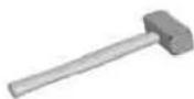
Socket wrench RubbflambletOpen-endedRplipser
size 7
size 10
screwdriver
(size 2-3)
screwdriver
(size 2-3)
Allen key
(size 4)
or ring spanner
(size 10 / 13)
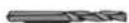
∅ 2.0 mm drill bit
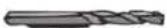

Drill or cordless screwdriver

or folding rule
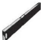
Spirit level Tape measure Safety stepladder

ScissorsMasonry drill

Please note:
All bags of components for installation and assembly contain spare nuts and bolts.
When assembling the greenhouse, make sure that the profiles are all perfectly square. Check the horizontal and vertical positions of the profiles with a spirit level. Make sure that all profiles are assembled in their defined end positions, pushed together as far as they will go.

Notes on the assembly instructions:
In the assembly instructions, the 5-panel model (2 panels + 3 panels) serves as a reference model. The overview diagrams all show this model. The other greenhouses are only different to this model in terms of the number of side panels. If you have purchased one of the other models, please refer to the relevant assembly instructions for your greenhouse.
Information on use / base / base diagram
Information on use of the greenhouse
- All bolts, screws and nuts should be checked every three months and retightened if required.
• After a storm or high winds please check all bolts, screws and nuts and ensure that the plastic web panels are correctly seated.
• In the event of a storm or heavy winds please close the doors and windows of your greenhouse. - Suitable storm anchoring (not included) should be used to additionally secure the greenhouse in areas particularly prone to storms.
- At temperatures below freezing (0 °C), never strike the plastic web panels with hard objects.
- Snow should be cleared from the roof of the greenhouse on a regular basis to prevent dangerous snow loads from building up. A 10 cm layer of snow or a 2 cm layer of ice can already be dangerous.
•The roof of your greenhouse is not designed to be walked on. - Never use any naked flames or similar in the greenhouse. Only use approved heating equipment.
•Always make sure that you comply with the local building regulations in your area.
Base
Please note: The greenhouse does not have a separate base profile. You can erect your greenhouse on a previously prepared brickwork or concrete base (see base diagram), or you can assemble it on a steel base (available as an optional accessory).

Important
If you do not want to erect your greenhouse on a masonry or concrete baseplate, ensure that your greenhouse is built on level, sturdy ground. Check levelness using a water level!
Concrete / brickwork base
It is very important for correct assembly of the greenhouse that the right angles in the base are all perfectly square. The base must be dead level, with perfectly square corners. Please use a spirit level to check. Please note: the base should be deep enough to be frostproof.
Base diagram
Concrete or brickwork base
Greenhouse La (cm) Li (cm) Ba (cm) Bi (cm) T (cm) H (cm)
3 panels 224 204 259 239 10 Frost-proof depth (30)
4 panels 295 275 259 239 10 Frost-proof depth (30)
5 panels 366 346 259 239 10 Frost-proof depth (30)
6 panels 437 417 259 239 10 Frost-proof depth (30)
7 panels 508 488 259 239 10 Frost-proof depth (30)
The base must be at least 10 cm wide (T) with a height (as required) of (h). The base must be dead level, with perfectly square corners.
Packing list - aluminum profiles
The aluminum profiles for your greenhouse are shipped in several packages.
3 panels
Aluminum profiles
| Package no. | Contents |
| 36.505.30 | Aluminum profiles -front wall with single door |
| 36.505.32 | Aluminum profiles - rear wall |
| 36.505.34 | Aluminum profiles - 3 panels |
4 panels with single door
Aluminum profiles
Package no. Contents
| 36.505.30 | Aluminum profiles -front wall with single door |
| 36.505.32 | Aluminum profiles - rear wall |
| 36.505.33 | Aluminum profiles - 2 panels |
| 36.505.33 | Aluminum profiles - 2 panels |
| 36.505.35 | Set of connecting elements |
4 panels with double door
Aluminum profiles
| Package no. | Contents |
| 36.505.31 | Aluminum profiles -front wall with double door |
| 36.505.32 | Aluminum profiles - rear wall |
| 36.505.33 | Aluminum profiles - 2 panels |
| 36.505.33 | Aluminum profiles - 2 panels |
| 36.505.35 | Set of connecting elements |
5 panels with single door
Aluminum profiles
Package no. Contents
| 36.505.30 | Aluminum profiles -front wall with single door |
| 36.505.32 | Aluminum profiles - rear wall |
| 36.505.33 | Aluminum profiles - 2 panels |
| 36.505.34 | Aluminum profiles - 3 panels |
| 36.505.35 | Set of connecting elements |
5 panels with double door
Aluminum profiles
| Package no. | Contents |
| 36.505.31 | Aluminum profiles -front wall with double door |
| 36.505.32 | Aluminum profiles - rear wall |
| 36.505.33 | Aluminum profiles - 2 panels |
| 36.505.34 | Aluminum profiles - 3 panels |
| 36.505.35 | Set of connecting elements |
6 panels
Aluminum profiles
Package no. Contents
| 36.505.31 | Aluminum profiles -front wall with double door |
| 36.505.32 | Aluminum profiles - rear wall |
| 36.505.34 | Aluminum profiles - 3 panels |
| 36.505.34 | Aluminum profiles - 3 panels |
| 36.505.35 | Set of connecting elements |
7 panels
Aluminum profiles
| Package no. | Contents |
| 36.505.31 | Aluminum profiles - front wall with double door |
| 36.505.32 | Aluminum profiles - rear wall |
| 36.505.33 | Aluminum profiles - 2 panels |
| 36.505.33 | Aluminum profiles - 2 panels |
| 36.505.34 | Aluminum profiles - 3 panels |
| 36.505.35 | Set of connecting elements |
| 36.505.35 | Set of connecting elements |
Notes on the assembly steps
To assemble the greenhouse, please follow the sequence of steps and the illustrations shown in the German assembly instructions. This accompanying booklet contains all of the important assembly information and any other important text in your language. The examples below show how the individual assembly steps and illustrations are laid out in the German instructions.
Overview
The right-hand text column contains an overview for each assembly step. The parts used in a given step are shown slightly darker to highlight them, and circles are used to indicate areas for which there is a detail drawing. In part these symbols are also used for assembly previews and reference diagrams for checking.
Assembly step
List of parts
At the start of each assembly step you will see a table containing a list of the parts required for this step. The table is divided into six columns: Article no., item no., picture, article description, size or length, quantity required. From step 12 on, varying quantities of different parts are required according to the greenhouse model purchased. In these tables, the quantity specifications are split into 5 columns (for greenhouse models with 3 to 7 panels). Use the stamped-on article number, the picture and the length/size information to identify the relevant parts.
Assembly note
From step 12 onwards, some of the steps need to be repeated different numbers of times. This depends on the greenhouse model purchased (3 panels to 7 panels). Please repeat these steps the appropriate number of times for your model.
Profile views
The detail drawings often include additional profile views for ease of understanding.
Tools
The tools required in a particular step are shown here.
Repetitions
This field shows the number of repetitions if the processes in the detail drawings need to be carried out several times.
bar
| Category | Value | |---|---| | Fruit | 1 | | Sugar | 1 | | Vegetable | 1 | | Vegetable | 1 | | Vegetable | 1 | | Vegetable | 1 | | Vegetable | 1 | | Vegetable | 1 | | Vegetable | 1 | | Vegetable | 1 | | Vegetable | 1 | | Vegetable | 1 | | Vegetable | 1 | | Vegetable | 1 | | Vegetable | 1 | | Vegetable | 1 | | Vegetable | 1 | | Vegetable | 1 | | Vegetable | 1 |
Übersichte

Hinweis:
The following pages contain the accompanying texts in your language. They are sorted according to the page numbers (German instructions) and by assembly step to make it easier to follow the corresponding texts in the German instructions.
Installation notes:
Page 7
Installation of the front wall assembly
1 Pre-assembly of the floor profile
Important note: For ease of handling, the front and rear walls should be assembled flat on the ground.
Bottom illustration: Assembly preview of the front wall with single door
Page 8
Top illustration: Front wall with double door
1/a: Slide the guide rails of the two floor profiles each into one connecting part up to the corresponding cutouts (see illustration.). Please refer to the relevant assembly instructions for your greenhouse for the exact position.
Page 9
1/c: Attach the floor gusset plate to the floor profile using an additional bolt. Make sure that this bolt is inserted on the left on the gusset plate mounted on the left and on the right on the gusset plate mounted on the right (see assembly preview details A and B).
Page 11
1/g: Make sure that the floor corner connectors are flush with the floor profile as shown in Fig. 1/g.
Page 12
② Assembly of the corner profiles
Page 13
Bottom illustration: Reference diagram (floor profile with corner profiles): Internal view
Page 14
3 Pre-assembly of the gable profiles
Top parts list: Front wall with single door
Bottom parts list: Front wall with double door
Important note: This step is repeated later on during assembly of the rear wall (see „Assembly of the rear wall assembly“). Please make sure that the rear wall is assembled in the same way as the front wall. Use the corresponding components (parts list: front wall with double door) and follow the corresponding steps.
Bottom illustration: Front wall with single door
Assembly preview / reference diagram (gable profiles): Internal view
Observe the correct positions for the bolts.
Page 15
Top illustration: Front wall with double door Assembly preview / reference diagram (gable profiles): Internal view
Observe the correct positions for the bolts.
Fig. 3/a: Front wall with single door
Fig. 3/b: Front wall with double door
Page 16
Important note: Make sure that the assembly panels are aligned in the way shown in the diagrams 3/c and 3/d. The assembly panels are not properly aligned until the ridge and the rain guttering are installed in a subsequent step.
Page 17
Important note: Make sure that the two (front wall with single door) or three (front wall with double door) pre-assembled bolts in the middle face inward. Please check the corresponding reference diagrams on the pages beforehand if you are unsure.
Page 18
Inspection page for the front wall with single door
Before progressing to step 4, please use the diagram below to check that all of the bolts required for the next step have been installed.
Illustration: Internal view – front wall with single door
Page 19
Inspection sheet for the front wall with double door
Before progressing to step 4, please use the diagram below to check that all of the bolts required for the next step have been installed.
Illustration: Internal view – front wall with double door
Page 20
4 Assembly of the gable profiles on the corner profiles
Page 21
5 Assembly of the crossmember
Important note: If you have purchased a greenhouse with a single door then assemble the crossmember as described in the steps 5/a and 5/b. For a greenhouse with a double door, follow steps 5/c and 5/d to assemble the crossmember.
Figs. 5/a + 5/b: Front wall with single door
Fig. 5/a: Make sure that the crossmember is installed symmetrically.
Page 22
Figs. 5/c + 5/d: Front wall with double door
Fig. 5/c: Make sure that the crossmember is installed symmetrically.
Page 23
6 Assembly of the roof strut
Page 24
7 Assembly of the door struts on a greenhouse with a single door
If you have purchased a greenhouse with a double door, skip step 7 and continue with step 8 „Assembly of the door struts on a greenhouse with a double door“.
7/a: Install two bolts at one end of each of the two door hinges, with one bolt around 60 cm and the other around 5 cm from the edge. At the other end attach one bolt around 30 cm and another around 5 cm from the edge.
Page 25
7/c: Slide the four pre-assembled hinge blades into the guide rail of one of the door hinges. Make sure that you screw down the hinge blades as shown in Fig. 7/d.
Page 26
7/e: Two countersunk screws (item 3) are loosely screwed into the two door strikers with M4 hexagon nuts (item 4).
Page 28
7/h: Working from the outside, position the door hinge between the floor profile and the crossmember and secure it at the top using the pre-assembled hexagon bolt. Make sure that the hinges face towards the middle.
Important note: The door hinge with the hinges is inserted on the left (viewed from the inside), the door
hinge with the striker plates on the right. Please refer to the reference diagram on the next page.
Page 29
Reference diagram - internal view
Illustration: Left-hand profile: door hinge with hinges Right-hand profile: door hinge with striker plates
Note: The cutouts on the floor profile and the crossmember marked with an X in the reference diagram stay free. Make sure that the door profile with the hinges and the door profile with the striker plates are inserted as shown in the reference diagram (internal view!).
Page 30
8 Assembly of the door struts on a greenhouse with a double door
If you have purchased a greenhouse with a single door, skip step 8 and continue with step 9 „Assembly of the wind bracing and struts“.
8/a: Install three bolts at one end of each of the two door hinges, with one bolt around 60 cm, one bolt around 30 cm and the other around 5 cm from the edge. At the other end attach one bolt around 30 cm and another around 5 cm from the edge.
Page 31
8/c + 8/d: Slide four pre-assembled hinge blades into the guide rail of one of the door hinges (see Fig. 8/c). Three hinge blades are attached to the second door hinge. Make sure that you screw down the hinge blades as shown in Fig, 8/d, so that the door can be subsequently inserted with the matching counterparts.
Page 32
8/e: Make sure that the hinges face towards the middle.
Important note: The door hinge with the four pre-assembled hinges is inserted on the left (viewed from the inside), the door hinge with the three hinges on the right. Please refer to the reference diagram on page 24 of the German assembly instructions.
Page 34
Reference diagram - internal view
Note: The cutouts on the floor profile and the crossmember marked with an X in the reference diagram stay free. Make sure that you insert the door profiles with the hinges as shown in the reference diagram (internal view!).
Page 35
9 Assembly of the wind bracing and struts
Top parts list: Front wall with single door
Bottom parts list: Front wall with double door
Note: Make sure that the struts are installed horizontally. If necessary, use a spirit level to check.
Page 36
Fig. 9/c: Front wall with single door
Page 37
Fig. 9/c: Front wall with double door
9/d: Install the two bottom struts so that the angled wind bracing fits in front of the one strut and behind the other (see reference diagram on the next page).
Page 38
Reference diagram (Fig. - Front wall with single door)
Note: Make sure that the struts are installed horizontally. If necessary, use a spirit level to check. Carefully tighten the bolts on the wind bracing and the struts. This provides the necessary stability for the front wall.
Page 39
Installation of the rear wall assembly
Repeat steps 1 to 6.
Please note: In step 1 „Pre-assembly of the floor profile“, use the floor gusset plate (art. no. 84.620.21) in place of the mounting bracket, short (art. no. 84.631.51) Working from the outside, attach the gusset plate to the floor profile at the two upper holes using two hexagon bolts and nuts.
After step 6 in the assembly go straight to step 10.
10 Assembly of the struts (rear wall)
Page 40
10/c: Make sure that the strut with the three pre-assembled bolts is inserted in the middle.
Page 42
Reference diagram (internal view)
Note: The cutouts on the floor profile and the crossmember marked with an X in the reference diagram stay free. Make sure that the strut with just three pre-assembled bolts is inserted in the middle! Check the distances between the bolts.
Page 43
11 Installation of the wind bracing and struts on the rear wall
Note: Make sure that the struts are installed horizontally. If necessary, use a spirit level to check.
Page 45
11/d + 11/e: Install the two bottom struts (DT) (602 mm) in such a way that the angled wind bracing fits in front of the one strut and behind the other (see Fig. 11/e).
Page 46
Note: Make sure that the struts are installed horizontally. If necessary, use a spirit level to check. Carefully tighten the bolts on the wind bracing and the struts. This provides the necessary stability for the front wall.
Page 47
12 Pre-assembly of the side floor profile
Middle illustration: Assembly preview of a greenhouse with 3 panels
Bottom illustration: Assembly preview of a greenhouse with 4 panels
Page 48
Top illustration: Assembly preview of a greenhouse with 5 panels
Middle illustration: Assembly preview of a greenhouse with 6 panels
Bottom illustration: Assembly preview of a greenhouse with 7 panels
Page 49
Important note: If you have purchased a 3-panel greenhouse, skip steps 12/a and 12/b and continue with assembly step 12/c.
Page 50
Important note: If you have purchased a steel base (optional accessory) for your 3-panel greenhouse, then you will need to install additional bolts on the floor profile. If you are not using a steel base, please skip step 12/c and continue with assembly step 12/d.
Fig. 12/c: Floor profile for a greenhouse with 3 panels
12/c: Slide three bolts into each floor profile guide rail of the 3-panel greenhouse (slide the bolts to the middle – see assembly preview). This will be needed
later on to attach it to the steel base (optional accessory). If you are not using a steel base then you do not need to fit these bolts.
12/d: Slide one bolt into each pre-assembled floor profile guide rail (bolt should be approx. 10 cm from the edge – see assembly preview).
Page 51

Pre-assembly of the rain guttering
Important note for 3-panel greenhouses: If you have purchased a 3-panel greenhouse, skip step 13 and continue with assembly step 15. No pre-assembly of the rain guttering is required on 3-panel greenhouses.
Bottom illustration: Assembly preview of a greenhouse with 4 panels
Page 52
Top illustration: Assembly preview of a greenhouse with 5 panels
Middle illustration: Assembly preview of a greenhouse with 6 panels
Bottom illustration: Assembly preview of a greenhouse with 7 panels
Page 55

Pre-assembly of the ridge
Important note for 3-panel greenhouses: If you have purchased a 3-panel greenhouse, skip step 14 and continue with assembly step 15. No pre-assembly of the ridge profile is required on 3-panel greenhouses.
Middle illustration: Assembly preview of a greenhouse with 4 panels
Bottom illustration: Assembly preview of a greenhouse with 5 panels
Page 56
Top illustration: Assembly preview of a greenhouse with 6 panels
Middle illustration: Assembly preview of a greenhouse with 7 panels
14/a: Slide the bolt with the fluted side first into the designated opening of the ridge profile.
Page 58

Assembly of the floor profile on the front and rear walls
15/a: Slide the floor profile which was already pre-assembled in step 12 (side) into the corner cover on the corner profile.
Important note: If you have purchased a 5-panel house, the side profiles must be assembled in such a way that the two shorter profiles (1414 mm) face the front wall.
Page 59

Assembly of the rain guttering profile on the front and rear walls
16/a: Slide the rain guttering profile as far as it will go onto the front or rear wall. It may be necessary to realign the corner and gable profiles to allow the rain guttering to be inserted with a perfect fit. To do this you will need to loosen the bolts on the assembly panel.
Important note: If you have purchased a 5-panel house, the rain guttering profiles must be assembled in such a way that the two shorter profiles (1414 mm) face the front wall.
Page 60

Assembly of the ridge profile on the front and rear walls
17/a: Slide the ridge as far as it will go onto the front or rear wall. It may be necessary to realign the gable profiles to allow the rain guttering to be inserted with a perfect fit. To do this you will need to loosen the bolts on the assembly panel.
Important note: If you have purchased a 5-panel house, the ridge profiles must be assembled in such a way that the shorter profile (1414 mm) faces the front wall.
Page 61

Assembly of the side struts
18/a: On the side struts, install one bolt approx. 5 cm from both the top and bottom edge. Please check the exact quantity required for your particular greenhouse model.
18/b: On the remaining side struts, install one bolt approx. 5 cm from the bottom edge. Two bolts are installed at the top, one approx. 10 cm, the other approx. 5 cm from the edge.
Page 62
18/c: Assemble the side struts with the four pre-assembled bolts (see step 18/b) on the gusset plates on the floor profile and the rain guttering.
Page 64

Assembly of the roof struts
Note: The side struts (roof) are inserted in the next step. Please make sure that you refer to the relevant
reference diagrams for your greenhouse and compare the pre-assembly steps (steps 19/a to 19/d) with these illustrations before you insert the struts. The roof struts with the bolts which have been pre-assembled in the middle (see Fig. 19/b and 19/d) will be required later on for assembly of the window crossmember and the window. The illustrations below show at which points the windows are inserted in your greenhouse.
Bottom illustration: Reference diagram for the roof: 3-panel greenhouse
Key:
- Position of the pre-assembled bolts
- 1 bolt
Page 65
Top illustration: Reference diagram for the roof: 4-panel greenhouse
Bottom illustration: Reference diagram for the roof: 5-panel greenhouse
Key:
- Position of the pre-assembled bolts
-1 bolt
-2 bolts - Position of the already assembled gusset plates on the ridge and the rain guttering
Page 66
Top illustration: Reference diagram for the roof: 6-panel greenhouse
Bottom illustration: Reference diagram for the roof: 7-panel greenhouse
Key:
- Position of the pre-assembled bolts
- 1 bolt
- 2 bolts
- Position of the already assembled gusset plates on the ridge and the rain guttering
Page 67
19/a: Please make sure you follow the assembly instructions and refer to the reference diagram for your particular greenhouse.
Page 69
19/e: First attach the side struts already assembled in steps 19/c and 19/d to the gusset plates (side). Insert the struts from the outside between the ridge and the rain guttering.
Page 71

Assembly of the window rabbet profile
Page 72
20/b: Insert the window rabbit profile from inside between the side struts (roof) with the bolts already pre-assembled in the middle (see reference diagrams in step 19). Make sure that the cutouts for the bolts face downward (see Fig. 20/c).
Page 73

Assembly of the gusset plates
Important note: If you have purchased a 3-panel greenhouse, skip step 21 and continue with assembly step 22.
21/a: Attach the gusset plates at an angle of 120^ to the struts on which the bolts have been pre-assembled.
Page 74
21/b: To finish with, attach a gusset plate at an angle of 120^ to the roof struts on which the bolts have been pre-assembled.
Page 75

Assembly of the side wind bracing
Note: During assembly of the side wind bracing, please make sure that you insert these wind bracing elements as described in the relevant assembly previews / reference diagrams (side).
Bottom illustration: Assembly preview / reference diagram (side): 3-panel greenhouse
Page 76
Top illustration: Assembly preview / reference diagram (side): 4-panel greenhouse
Bottom illustration: Assembly preview / reference diagram (side): 5-panel greenhouse
Page 77
Top illustration: Assembly preview / reference diagram (side): 6-panel greenhouse
Bottom illustration: Assembly preview / reference diagram (side): 7-panel greenhouse
Page 79

Assembly of the roof wind bracing
Note: During assembly of the roof wind bracing, please make sure that you insert the wind bracing elements as described in the relevant assembly previews / reference diagrams (roof). This is essential for providing the required stability for the greenhouse.
The delivery package for the 3-panel, 5-panel and 6-panel greenhouse contain more wind bracing elements than you will need for assembly.
Bottom illustration: Assembly preview / reference diagram (roof): 3-panel greenhouse
Page 80
Top illustration: Assembly preview / reference diagram (roof): 4-panel greenhouse
Bottom illustration: Assembly preview / reference diagram (roof): 5-panel greenhouse
Page 81
Top illustration: Assembly preview / reference diagram (roof): 6-panel greenhouse
Bottom illustration: Assembly preview / reference diagram (roof): 7-panel greenhouse
Important note: Please note that on a 7-panel greenhouse no wind bracing is inserted between the two middle segments.
Page 83
Installation of the base assembly
Important note: Before proceeding to part 2 of the assembly instructions, you will need to position your greenhouse in its final position and attach it to its base (concrete, brickwork or steel base). Later on it will no longer be possible to move the greenhouse. If you are positioning your greenhouse on a concrete / brickwork base, continue with this assembly step. If you have purchased the steel base (not included as part of the standard delivery package), then install it as described in the assembly instructions for the steel base.
Anchoring on a concrete / brickwork base
The following additional installation materials are required for anchoring the greenhouse on a concrete or brickwork base (not included in the delivery package):
- Anchor fittings / dowels
- Hexagon-head wood screws
- Washers
You will require 1 each of these items for every floor corner connector and 2 each for every floor gusset plate and the mounting bracket.
Please note: Use anchor fittings / dowels which are suitable for a concrete / brickwork base. Holes need to be pre-drilled in the base for the anchor fittings / dowels.
To mark the holes, position the greenhouse on the base and mark the positions of the holes for the mounting brackets.
Page 86
Optional accessories (not included in the delivery package)
Art. no. 36.405.90: Anchoring set BD4 (4 x ground anchors)
Art. no. 36.405.91: Anchoring set BD6 (6 x ground anchors)
Note: The anchoring set is used to secure the greenhouse or the steel base in the ground. Please refer to the overviews below for information about the number of anchoring sets required for your particular greenhouse. The positions at which the individual ground anchors are secured are marked with circles. In order to fix the exact positions of the ground anchors, position the greenhouse in its final position. Then mark the positions where the ground anchors will be installed.
Middle illustration: View from above, 3-panel greenhouseAnchor sets required: 2 x sets BD4 (art. no. 36.405.90)
Bottom illustration: View from above, 4-panel greenhouseAnchor sets required: 1 x set BD4 (art. no. 36.405.90) + 1 x set BD6 (art. no. 36.405.91)
Page 87
Top illustration: View from above, 5-panel greenhouseAnchor sets required: 1 x set BD4 (art. no. 36.405.90) + 1 x set BD6 (art. no. 36.405.91)
Middle illustration: View from above, 6-panel greenhouseAnchor sets required: 1 x set BD4 (art. no. 36.405.90) + 1 x set BD6 (art. no. 36.405.91)
Bottom illustration: View from above, 7-panel greenhouseAnchor sets required: 1 x set BD4 (art. no. 36.405.90) + 1 x set BD6 (art. no. 36.405.91)

bar
| Category | Value | |---|---| | Fruit | 1 | | Sugar | 1 | | Vegetable | 1 | | Vegetable | 1 | | Vegetable | 1 | | Vegetable | 1 | | Vegetable | 1 | | Vegetable | 1 | | Vegetable | 1 | | Vegetable | 1 | | Vegetable | 1 | | Vegetable | 1 | | Vegetable | 1 | | Vegetable | 1 | | Vegetable | 1 | | Vegetable | 1 | | Vegetable | 1 | | Vegetable | 1 | | Vegetable | 1 |

Übersichts

Hinweis:
bar
| Category | Value | |---|---| | Fruit | 1 | | Sugar | 1 | | Vegetable | 1 | | Vegetable | 1 | | Vegetable | 1 | | Vegetable | 1 | | Vegetable | 1 | | Vegetable | 1 | | Vegetable | 1 | | Vegetable | 1 | | Vegetable | 1 | | Vegetable | 1 | | Vegetable | 1 | | Vegetable | 1 | | Vegetable | 1 | | Vegetable | 1 | | Vegetable | 1 | | Vegetable | 1 | | Vegetable | 1 |

Übersichte

Hinweis:
bar
| Category | Value | |---|---| | Fruit | 1 | | Sugar | 1 | | Vegetable | 1 | | Vegetable | 1 | | Vegetable | 1 | | Vegetable | 1 | | Vegetable | 1 | | Vegetable | 1 | | Vegetable | 1 | | Vegetable | 1 | | Vegetable | 1 | | Vegetable | 1 | | Vegetable | 1 | | Vegetable | 1 | | Vegetable | 1 | | Vegetable | 1 | | Vegetable | 1 | | Vegetable | 1 | | Vegetable | 1 |

Übersichts
Hinweis:
bar
| Category | Value | |---|---| | Fruit | 1 | | Sugar | 1 | | Vegetable | 1 | | Vegetable | 1 | | Vegetable | 1 | | Vegetable | 1 | | Vegetable | 1 | | Vegetable | 1 | | Vegetable | 1 | | Vegetable | 1 | | Vegetable | 1 | | Vegetable | 1 | | Vegetable | 1 | | Vegetable | 1 | | Vegetable | 1 | | Vegetable | 1 | | Vegetable | 1 | | Vegetable | 1 | | Vegetable | 1 |

Übersichte

Hinweis:
bar
| Category | Value | |---|---| | Fruit | 1 | | Sugar | 1 | | Vegetable | 1 | | Vegetable | 1 | | Vegetable | 1 | | Vegetable | 1 | | Vegetable | 1 | | Vegetable | 1 | | Vegetable | 1 | | Vegetable | 1 | | Vegetable | 1 | | Vegetable | 1 | | Vegetable | 1 | | Vegetable | 1 | | Vegetable | 1 | | Vegetable | 1 | | Vegetable | 1 | | Vegetable | 1 | | Vegetable | 1 |

Übersichte

Hinweis:
Unit 5 Morpeth Wharf
Twelve Quays
Birkenhead, Wirral
CH 41 1NG
Tel. 0151 6491500, Fax 0151 6491501
F METLAND
Z.I. Des Renardières
Rue des Vignes
F-77250 Ecuelles
Tel. 01 64316211; Fax 01 64316201
mail: sav@metland.fr
NL Einhell Benelux
B Veldsteen 44
NL-4815 PK Breda
Tel. 076 5986470, Fax 076 5986478
E Comercial Einhell, S.A.
Travesia Villa Ester, 9 B
Poligono Industrial El Nogal
E-28119 Algete-Madrid
© Einhell Portugal Lda.
Apartado 2100
Technical & Commercial Company
12, Papastratou & Asklipiou Str.
GR 18545 Piräus
Tel 0210 4136155, Fax 0210 4137692
RUS Bermas, Moscow
Altufyevskoe shosse, 2A
RUS-127273 Moscow
Tel. 095 5401750 (central office)
Tel. 095 9033761 (Repair center Moscow)
Tel. 812 2240544 (Repair center St. Petersburg)
LTDirbita
Lv Metalo str. 23
LT-02190 Vilnius
Tel 05 2395769, Fax 05 2395770
ESTAS Baltoil
Roiu alev
Haaslava vald
EE-62102 Tartu
Tel 07 301 700, Fax 07 301 701
IR Alborz Abzar Co. Ltd.
No. 111, Bastan Passage, Imam Khomeini Ave.
IR-11146 Teheran
Tel 021 6716072, Fax 021 6727177
Bih Einhell BiH d.o.o.
Poslovni Centar 96
BA-72250 Vitez
Tel 030 717250, Fax 030 717255
ZA Eurasia Industrial and Automotive Supply
3, Bessemer Str.
Duncanville
ZA-Vereeniging 1939
Tel 016 455 571 2, Fax 016 455 571 6
BY Svyaz Prominvest Ltd.
207-11, Skariny av.
BY-220023 Minsk
Tel 017 2642777, Fax 017 2642591
scqWoby House
Brace Ribnikara 55
SCG-21000 Novi Sad
Tel 021 4722216, Fax 021 4722217
EH 08/2005 - Ver. 05
GB WARRANTY CERTIFICATE
The product described in these instructions comes with a 2-year warranty covering defects. This 2-year warranty period begins with the passing of risk or when the customer receives the product.
For warranty claims to be accepted, the product has to receive the correct maintenance and be put to the proper use as described in the operating instructions.
Your statutory rights of warranty are naturally unaffected during these 2 years.
This warranty applies in Germany, or in the respective country of the manufacturer's main regional sales partner, as a supplement to local regulations. Please note the details for contacting the customer service center responsible for your region or the service address listed below.
F GARANTIE
GB Technical changes subject to change