by Fluid Signature R90W - Rowing Machine TUNTURI - Free user manual and instructions
Find the device manual for free by Fluid Signature R90W TUNTURI in PDF.

User questions about by Fluid Signature R90W TUNTURI
0 question about this device. Answer the ones you know or ask your own.
Ask a new question about this device
Download the instructions for your Rowing Machine in PDF format for free! Find your manual by Fluid Signature R90W - TUNTURI and take your electronic device back in hand. On this page are published all the documents necessary for the use of your device. by Fluid Signature R90W by TUNTURI.
USER MANUAL by Fluid Signature R90W TUNTURI
natural_image
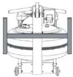
Technical line drawing of a mechanical machine with no visible text or symbolsFeaturing Patented Adjustable
Fluid Resistance Technology
www.fluid-eu.com
English
Introduction....2
Safety....3
Assembly 5
Rower Box 1 & 2 Contents....6
Assembly Instructions....7
Operation Instructions....10
Bluetooth Auto-Adjust Monitor....13
Calibration Procedure ....13
Monitor and APP Connectivity....14
Bluetooth Heart Rate Pairing 14
Detaching the Rower Belt 14
Reattaching the Rower Belt....15
Maintenance....16
Troubleshooting....16
Storage Support Bracket Instructions ....17
International Warranty 18
Deutsch
Einführung....19
Sicherheit....20
Aufbau....22
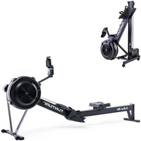
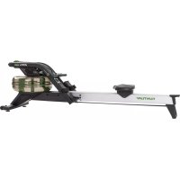
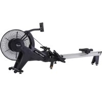
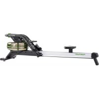
Congratulations on your purchase of the Rower.
FLUID is proud to present the Rower as home use product featuring patented Adjustable Fluid Resistance.
Our unique combination of precision steel and solid wood frames incorporate only the highest quality American Ash which is collected using the latest technology in sustainable harvesting from renewable plantations.
Note that slight variations of colour are normal and part of Mother nature's artistry. The wood grain patterns and subtle hues of each Rower makes every unit highly individual and designed to compliment any environment.
Follow all instructions carefully for correct assembly, Tank filling, Water Treatment, service and safety.
Access to our world-wide distributor and service network is available at www.fluid-eu.com
Check contents of Box 1 and 2 to ensure all parts are present and correct prior to assembly.
Training With the Rower
- As with any piece of fitness equipment, consult a physician before beginning your Rower exercise program.
- Follow instructions provided in this manual for correct foot position and basic rowing techniques.
- For more detailed rowing techniques, please refer to our international website at www.fluid-eu.com
Safety Information
- Before using this product, it is essential to read this ENTIRE operation manual and ALL instructions. The Rower is intended for use solely in the manner described in this manual.
• UNDERSTANDING EACH AND EVERY WARNING TO THE FULLEST IS IMPORTANT - As with any piece of fitness equipment, consult a physician before beginning your Rower exercise program.
- Please be aware that any fitness regime, before being undertaken, is best preceded by a physical checkup from a certified physician.
• Injuries to health may result from incorrect or excessive training. - Stop the machine immediately if any signs of excessive wearing is present on the Belts, Pulleys and Bungee cords. Do not use unit until said parts are repaired or replaced.
- Do not allow children unattended access to the machine.
- The Rower can stand vertically for storage. When doing so, please follow the instructions given in the manual.
- If any of the adjustment devices are left projecting, they could interfere with the user's movement.
- Do not store in freezing conditions with water in the Tank as it can expand and crack the components.
Proper Usage
- Do not use any equipment in any way other than designed or intended by the manufacturer. It is imperative that FLUID equipment is used properly to avoid injury.
- Injuries may result if exercising improperly or excessively. It is recommended that all individuals consult a physician prior to commencing an exercise program. If at any time during exercise you feel faint, dizzy or experience pain, STOP EXERCISING and consult your physician.
- Keep body parts (hands, feet, hair, etc.), clothing and jewelry away from moving parts to avoid injury.
- Follow instructions provided in this manual for correct foot position and basic rowing techniques.
- For more detailed rowing techniques, please refer to our International website www.fluid-eu.com
Inspection
- DO NOT use or permit use of any equipment that is damaged and/or has worn or broken parts. For all Tunturi New Fitness BVequipment use only replacement parts supplied by FLUID.
- Cables and Belts pose an extreme liability if used when frayed. Always replace any cable or Belt at first sign of wear (consult FLUID if uncertain).
- EQUIPMENT MAINTENANCE - Preventative maintenance is the key to smooth operating equipment as well as to keep your liability to a minimum. Equipment needs to be inspected at regular intervals.
- Ensure that any person(s) making adjustments or performing maintenance or repair of any kind is qualified to do so.
- DO NOT ATTEMPT TO USE OR REPAIR ANY ACCESSORY APPROVED FOR USE WITH THE FLUID BVEQUIPMENT WHICH APPEARS TO BE DAMAGED OR WORN.
- Check all Belts, pulleys and bungee cords regularly for signs of wear, and replace if needed.
- Check regularly and follow all instructions for maintenance as specified in this manual.
- Replace immediately any defective parts and do not operate unit until all repairs are complete.
Operating Warnings
- Keep children away from the equipment. Parents or others supervising children must provide close supervision of children if the equipment is used in the presence of children.
- Do not allow users to wear loose fitting clothing or jewelry while using equipment. It is also recommended to have users secure long hair back and up to avoid contact with moving parts.
- All bystanders must stay clear of all users, moving parts and attached accessories and components while machine is in operation.
- WARNING Do not insert fingers into Tank!
- CAUTION After rowing exercise, please allow the unit to sit for 5 minutes before standing it up for storage.
- CAUTION Do not fill past the calibration mark as indicated on the Tank level sticker or water spillage can occur.
- WARNING Never operate this Rower without feet properly secured in Footstraps, or without the sliding portion of the Slider Footplate locked into position!

CAUTION
- Keep hands and fingers away from moving parts, as indicated in this manual.
- The Rower can stand vertically for storage. Make sure a secure location is chosen, such as the corner of a room or against a wall on an even, secure surface.
- It is recommended not to expose the machine to the direct sunlight. It may cause accelerated aging of the plastic material, reduce the life of the tank shell and even lead to deformation and rupture.

NOTE
If the storage area is not level, an additional fixture is required (sold separately) to keep the Rower stable with vertical storage position.
Product Specifications
Product Class: HC
raking System: Speed Independent
Product Net Weight: 31.84kg (70.18lb)
Product Gross Weight: 37.79kg (83.29lb)
Minimum Safe Operating Surface Area: 333cm (131.09") × 172cm (67.71")
Dimensions: 2130mm (83.86") Length x 520mm (20.47") Width x 560mm (22.04") Height
Maximum User Weight: 150kg (330lb)
Compact Footprint: 2130 x 520mm or upright 560 x 540mm
Installation
- Place on a stable, flat surface in a horizontal position during use for maximum stability.
- Check all Belts, pulleys and bungee cords regularly for signs of wear, and replace if needed.
- Check regularly and follow all instructions for maintenance as specified in this manual.
- Replace immediately any defective parts and do not operate unit until all repairs are complete.
Product Highlights
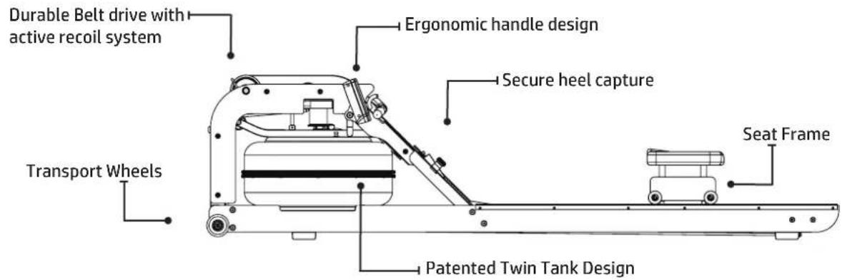
text_image
Durable Belt drive with active recoil system Transport Wheels Ergonomic handle design Secure heel capture Seat Frame Patented Twin Tank DesignLive Area and Training Area
The live area shall be not less than 60cm (23.62") greater than the training area in the directions from which the equipment is accessed. The live area must also include the area for emergency dismount.
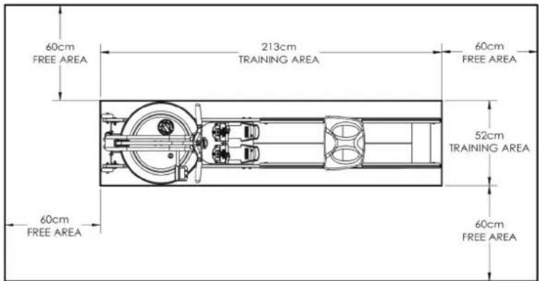
text_image
60cm FREE AREA 213cm TRAINING AREA 60cm FREE AREA 52cm TRAINING AREA 60cm FREE AREA 60cm FREE AREANote: Rower is not suitable for therapeutic purposes.

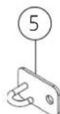
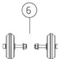
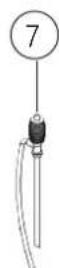
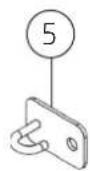
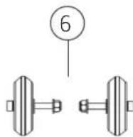
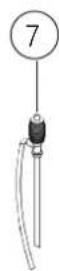
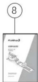
Rower Box 1 & 2 Contents
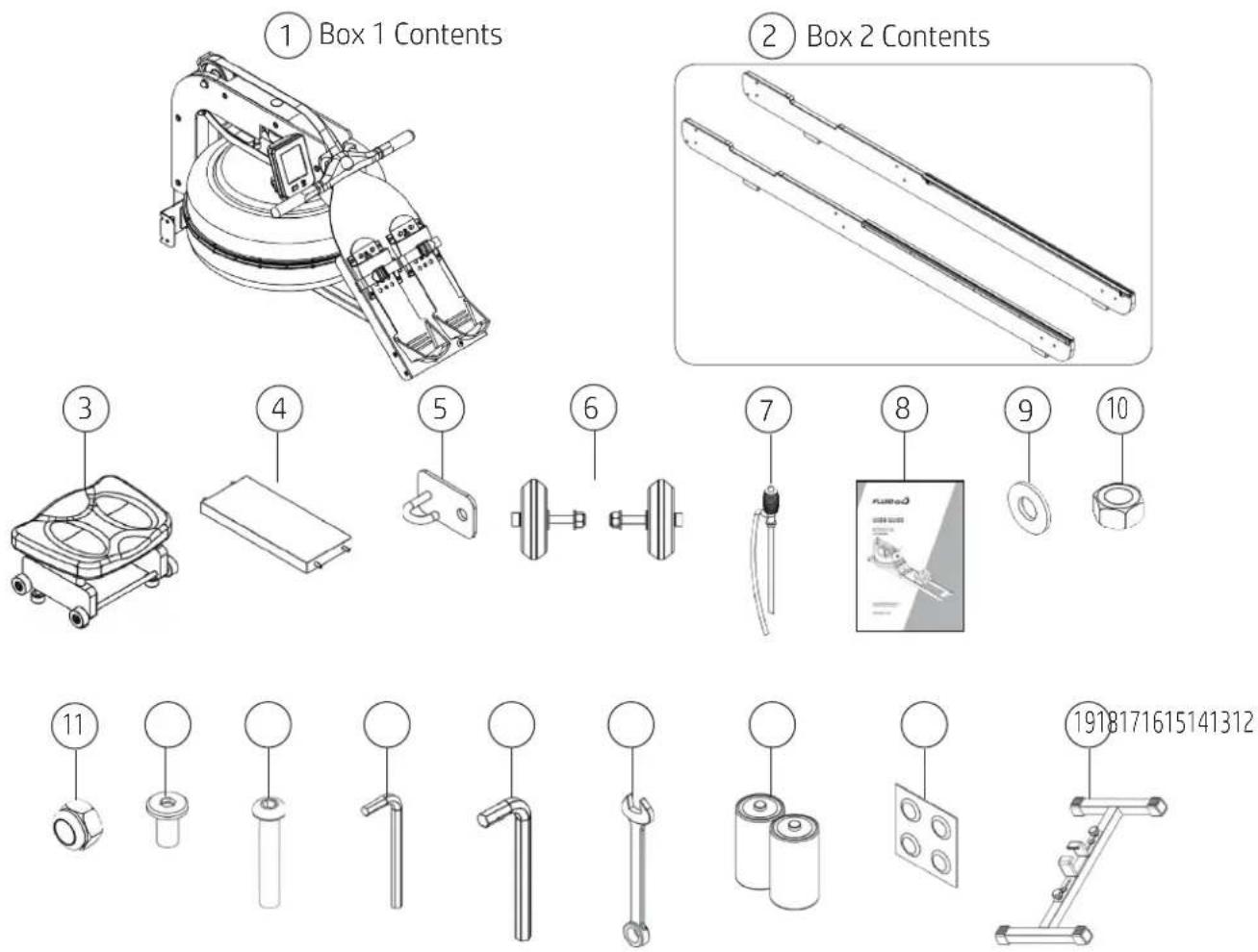
text_image
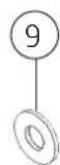
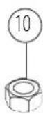
① Box 1 Contents ② Box 2 Contents ③ ④ ⑤ ⑥ ⑦ ⑧ ⑨ ⑩ ⑪ ⑫ ⑬ ⑭ ⑮ ⑯ ⑰ ⑱ ⑲ ⑳ ㉑ ㉒ ㉓ ㉔ ㉕ ㉖ ㉗ ㉘ ㉙ ㉚ ㉛ ㉜ ㉝ ㉞ ㉟ ㉳ ㉴ ㉵ ㉜ ㉝ ㉞ ㉟ ㉞ ㉟ ㉞ ㉞| Item Qty. Description Item Qty. Description | ||||||
 in Fi in Fi     | 1 | Bunge  2ok M 2ok M t t  | ||||
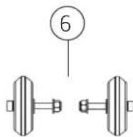
| 2 | 2 | Left / Right Side Rail | 6 | 2 | Transport Wheel Assembly | |
| 3 1 | Rower | Seat | 7 | 1 | Siphon | |
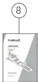
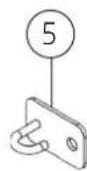
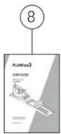
| 4 1 | Rear Brace | 8 | 1 | User Guide | ||
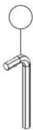
| Hardware KIT | ||||||
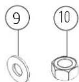
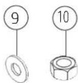
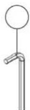
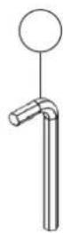
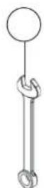
| 9 | 16 | M8 Washer | 14 | 1 | 5mm Allen Key | |
| 10 | 8 | M8 Standard Nut | 15 | 1 | 6mm Allen Key | |
| 11 | 8 | M8 Nyloc Nut | 16 | 1 | 13mm Spanner | |
| 12 | 4 | M6x15mm Bolt | 17 | 2 | D Cell Battery | |
| 13 | 8 | M8x45mm Bolt | 18 | 4 | Water Treatment Tablet | |
| Optional Equipment (Not Included) | ||||||
| 19 | 1 | Storage Support Bracket | 21 | 1 | Touch Heart Rate Handle | |
| 20 | 1 | Elevate Kit | 22 | 1 | Smart Phone Holder | |

Hardware KIT
| 9 | 16 | M8 Washer | 14 | 1 | 5mm Allen Key |
| 10 | 8 | M8 Standard Nut | 15 | 1 | 6mm Allen Key |
| 11 | 8 | M8 Nyloc Nut | 16 | 1 | 13mm Spanner |
| 12 | 4 | M6x15mm Bolt | 17 | 2 | D Cell Battery |
| 13 | 8 | M8x45mm Bolt | 18 | 4 | Water Treatment Tablet |
Optional Equipment (Not Included)
| 19 | 1 | Storage Support Bracket | 21 | 1 | Touch Heart Rate Handle |
| 20 | 1 | Elevate Kit | 22 | 1 | Smart Phone Holder |
STEP 1
Installing the Rear Brace and Transport Wheel Assembly to the Side Rails
REQUIRED
Side Rail Left / Right [2]
Rear Brace [4]
Bungee Hook Mount [5]
Transport Wheel Assembly [6]
4x M6x15mm Bolts [12]
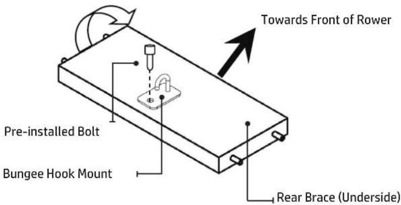
A) Start with the Rear Brace and on the underside you will find a Pre-installed bolt. From the Hardware Kit, take the Bungee Hook Mount and install it onto the Rear Brace as shown. Note the orientation of the Brace and Hook must be correct in order to hold the end of the Bungee Shock Cord as depicted by the arrow in the illustration, which points toward the front of Rower.

WARNING
Rotate Rear Brace to correct orientation before assembly onto Side Rails

NOTE
Transport Wheels must be mounted on the outside of Side Rails as shown below. Do not over tighten the Transport Wheel Axle as it may inhibit Transport Wheel rotation.
text_image
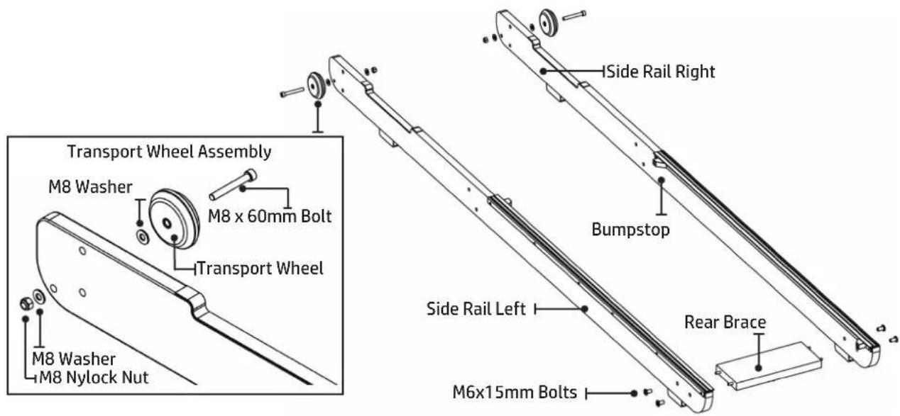
Towards Front of Rower Pre-installed Bolt Bungee Hook Mount Rear Brace (Underside)B) Next, connect the Side Rail Left and Side Rail Right[2] using 4x M6x15mm Bolts[12] and Rear Brace[4]. DO NOT TIGHTEN.
Tip: Bumpstops facing inside of rail for correct assembly orientation.
C) Once the Rear Brace and Side Rails are assembled, mount the Transport Wheel Assembly[6] onto the Left/Right Side Rails[2]. Note: One Washer on outside and one Washer on the inside of the side rail.
text_image
Transport Wheel Assembly M8 Washer M8 x 60mm Bolt Transport Wheel M8 Washer M8 Nylock Nut Side Rail Right Bumpstop Side Rail Left Rear Brace M6x15mm BoltsSTEP 2
Mounting Rower Seat and Upper Main Frame
REQUIRED
Left / Right Side Rail [2]
Rower Seat [3]
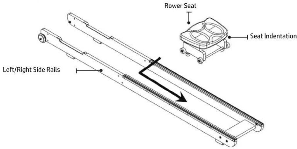
To Install the Rower Seat, spread the Left/Right Side Rails[2] slightly and drop the Rower Seat[3] into the track.
Note: Seat Indentation must face rearward.
text_image
Rower Seat Seat Indentation Left/Right Side RailsSTEP 3
Mounting Rower Seat and Upper Main Frame
REQUIRED
Main Frame [1]
Side Rails Assembly [2]
16x M8 Washers [9]
8x M8 Standard Nuts [10]
8x M8 Nyloc Nuts [11]
8x M8x45mm Bolts [13]
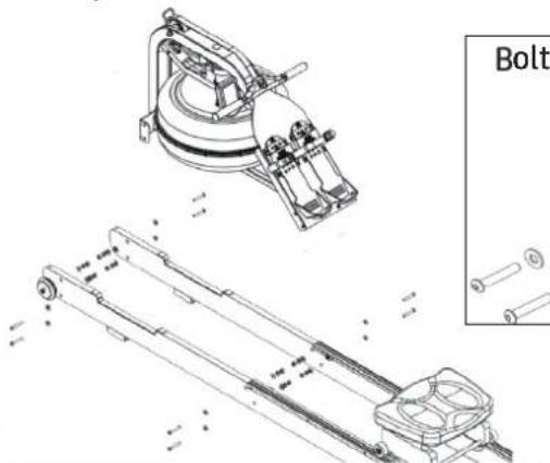
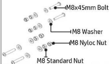
Next, install the Main Frame[1] onto the Side Rail Assembly[2] as shown. You will need 8x M8x45mm Bolts[13], 16x M8 Washers[9], 8x M8 Standard Nuts[10] and 8x M8 Nyloc Nuts[11].
Secure the front Lower Bracket first, then the Footboard but DO NOT TIGHTEN. You may find that the Lower Bracket Bolts can be difficult to access. You can tighten these bolts completely once the Rower is standing in the vertical position so for the moment, simply align and loosely thread lower Bolts/Nuts.

CAUTION
Nyloc Nuts must be outside the standard Nut and Washer to properly secure assembly.

NOTE
Clean Wheels and tracks weekly with a soft dry cloth in order to decrease the rate of wear on both Wheels and track.
natural_image
Technical line drawing of a mechanical assembly with exploded and assembled views, no text or symbols presentBolt Assembly Close Up
text_image
M8x45mm Bolt M8 Washer M8 Nyloc Nut M8 Standard Nut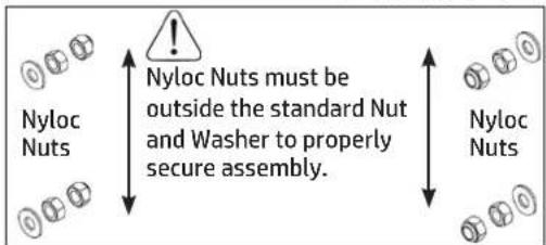
text_image
Nyloc Nuts must be outside the standard Nut and Washer to properly secure assembly. Nyloc Nuts Nyloc NutsSTEP 4
Attach Bungee Code And Completing the Rower Assembly

text_image
Tighten Frame Bolts securely once Rower is standing.Pull Bungee Cord and Hook Bungee End onto the Bungee Hook Mount[5] as shown.

Do not cut Bungee tie wrap before Bungee cord is attached to rear of Rower as shown here.
Once the Bungee Cord is attached to the Rear Brace, tighten the Bolts holding the Footboard, the Main Frame to Side Rail Bolts as they are easier to access from the vertical position.
Lower the Rower back to the Horizontal position and test for proper bungee recoil.
Check Seat Rollers/Runners for dirt or debris before sitting on the Rower Seat. Small objects captured between the Seat Rollers and Runners can damage the Wheels or running surface. Check Runners for debris prior to each use and clean regularly.
Note: The Rower Frame Bolts require periodic checking for tightness. Do this at the end of the first month of use and again after every 12 months.
Choose a suitable location when standing the product for storage.
The Rower Frame can be polished with any high grade furniture polish to further highlight the rich luster of the wood finish.
Install supplied 2x D Cell Battery and check Monitor function. Details regarding can be found in the Monitor section of this manual.
Choose a flat, level surface on which to use your Rower, to avoid rocking and potential premature wear.

Operation Instructions
Adjustable Resistance (AR) Tank
The adjustable resistance (AR) Tank, developed and patented by Tunturi New Fitness BV. offers a true multi-level experience. Water is moved between the "storage" and "active" chambers of the AR Tank. Your new rowing ergometer can adapt - at the turn of a dial - to the resistance preferred by each user.
Getting Started
To achieve minimum resistance, select "1" on the Tank adjuster. It takes 10 strokes to fill the central (storage) tank, leaving a minimal amount of water in the outer (active) tank. This process is always required if minimum resistance is desired. Row hard at a steady pace (20 to 25 strokes per minute [SPM]) and put some effort into the stroke, ensuring that good form is maintained. You can make adjustments to the resistance level while you row. Your AR Tank will adapt almost instantly to increases in resistance but will take up to 10 strokes to reduce the effort required, as the central (storage) Tank fills up.
Developing Your Routine
Once you have found a level that gives you the exercise required, changes can be made to SPM and to stroke intensity to further vary your energy input. Interval training is used by most Rowers, where a period of low intensity is combined with short intervals of high intensity. Your FLUID rowing ergometer allows for changes 'on the fly', to achieve multi-level resistance profiles during a single workout. For more information on exercise routines, please visit our website at www.fluid-eu.com
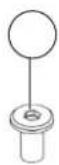
Tank Filling and Water Treatment Procedures
REQUIRED
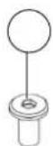
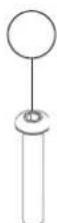
Siphon [7]
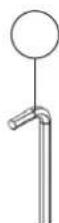
![TUNTURI by Fluid Signature R90W - Siphon [7] - 1](/content/2026/04/698005/images/6becd16a2d1012bcd5e8b261df2a3167c976d1401109279d94d65ff19095a5c9.jpg)
CAUTION
Resistance adjuster must be set to LEVEL 5 to allow for accurate filling capacity.

WARNING
Do not overfill the tank beyond the maximum indicated level of 17 liters. Refer to the Tank Level decal on the lower side of the tank.

NOTE
In areas where tap water quality is known to be poor, FLUID recommends the use of distilled water.
A) Remove Tank Plug from the top of the Tank.
B) Place a large bucket of water next to the Rower. Position the Siphon[7] with rigid hose in the bucket, and flexible hose in the Tank.
NOTE: Make sure small breather valve on siphon is closed before filling.
C) Squeeze siphon to begin filling. Important: Do not overfill Tank.
D) When full, open the valve on the top of the Siphon to allow excess water to escape.
E) Once filling is completed follow the water treatment schedule below, then replace the Tank Plug.

text_image
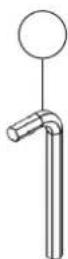
Siphon Tank Plug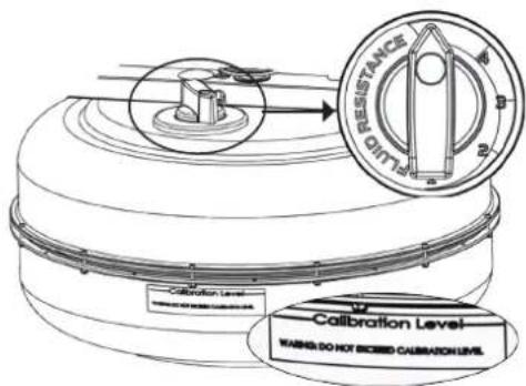
text_image
DRESSANCE DRESSANCE DRESSANCE DRESSANCE DRESSANCE DRESSANCE DRESSANCE DRESSANCE DRESSANCE DRESSANCE DRESSANCE DRESSANCE DRESSANCE DRESSANCE DRESSANCE DRESSANCE DRESSANCE DRESSANCE DRESSANCE DRESSANCE DRESSANCE DRESSANCE DRESSANCE DRESSANCE DRESSANCE DRESSANCELevel 1: This setting keeps a portion of the water in reserve creating light resistance.
Level 5: This setting allows the maximum amount of water to reach the flywheel for heaviest resistance.
Removing/Changing Tank Water
text_image
FLUID RESISTANCE 2 3 4 5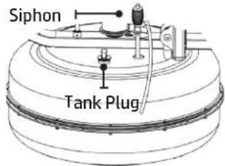
text_image
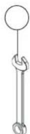
Siphon Tank PlugA) Set Adjuster Knob to "1"
B) Row at least ten strokes to fill the storage reservoir as completely as possible.
C) Remove Tank Plug.
D) Insert rigid end of siphon into the Tank, and flexible hose into a large bucket.
E) Drain Tank (approx. 40% of water will remain) and then refill following directions for Tank filling as described in the Tank Filling section of this manual.
NOTE:
- The valve on top of the siphon must be closed to allow proper drainage.
- Water treatment will preclude the need to change tank water if the treatment schedule is maintained.
- Additional Water Treatment Tablet is required only when discoloration appears in the water.
- Exposure to full sunlight reduces the life of the Water Treatment Tablets. Storing the Rower away from direct sunlight will extend the time between water treatments.
- Approximately 40% of tank water will remain. It is not possible to completely drain the A/R tank without disassembly.
NOTE: For simple, fast and efficient filling and/or drainage of the Tank, we have a battery operated pump (rechargeable via USB) available as an option. We recommend this to any commercial facility, with multiple units, that has a need to drain and refill Tanks from time to time. To purchase, contact your nearest Tunturi New Fitness BVdistributor or go to our website on www.fluid-eu.com for details.

CAUTION
It is strongly recommended that a drop cloth be used under the Tank whenever the Tank Plug is opened for water treatment.
Initial Water Treatment
Add One Water Treatment Tablet per full Tank. DO NOT, UNDER ANY CIRCUMSTANCE, USE A WATER TREATMENT TABLET OTHER THAN THOSE SUPPLIED WITH YOUR UNIT.
Your unit purchase includes 4xWater Treatment Tablets, which is sufficient for several years of use. The amount of time between water treatments can vary greatly depending on your unit's location and exposure to sunlight. Typically you can expect to treat your Tank water every 12-24 months. If water becomes discolored or shows signs of algae / bacterial growth simply add one Water Treatment Tablet. To purchase additional Water Treatment Tablets, please consult your nearest regional dealer/distributor or check our website at www.fluid-eu.com
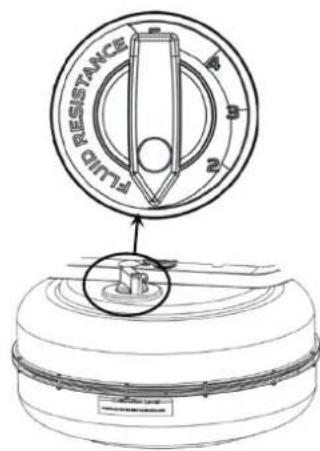
How to Adjust Resistance
Select your preferred Fluid Resistance.
NOTE: The Monitor level will automatically reflect the Fluid Resistance selected at the Tank.
When adjusting resistance level, allow two strokes to feel an increase and ten strokes to feel a decrease.


MINIMUM MAXIMUM
Start Rowing
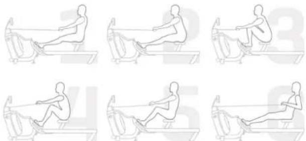
There are six phases to completing a rowing stroke
-
Sit with straight legs and back, leaning forward slightly at the hips with arms out straight and hands level with the lower ribs. Swing back.
-
Legs and back straight, leaning slightly forward from the hips, arms out in front. Lean and slide forward.
Note: Hands should now be around your knees, keeping legs straight.
- Legs come forward, aiming to get the shins vertical. Back is still straight, and posture leaning slightly forward with arms still out front. Now drive hard, this is the CATCH.
- Knees partially straightened so seat is now at mid-point of travel, back and arms still straight. Maintain the stroke.
- Knees are nearly straight, back is still straight but now leaning slightly back from the hips. Arms straight. Now squeeze through.
- Legs now fully extended. Back straight and leaning slightly back, now pull with the arms so they are close to the chest, forearms horizontal and elbows close in to the rib cage. This is the FINISH.
For more information on correct rowing technique and workout tips visit our website
www.fluid-eu.com
CAUTION: Always consult a doctor before beginning an exercise program. Stop immediately if you feel faint or dizzy.
CAUTION: Do not row to one side.
Adjust Footplates
The Footplate Slider accommodates most foot sizes, and is designed to keep your feet securely in place as you row. The feet should be positioned so that the foot strap covers the section of the foot naturally bend as row. (e.g. The board of the foot)
TO ADJUST:
Lift the top of the Footplate from the mounting pegs and slide vertically between 1-6 to suit your foot length. Secure by hooking the Footplate back onto the mounting pegs and pushing down firmly to lock it into position. Place feet on the foot plates and tighten the Footstraps to ensure your feet sit firmly against the heel captures.
Note: The heel capture should bend to allow your foot to pivot naturally as you row.
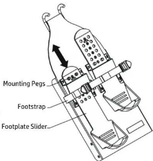
text_image
Mounting Pegs Footstrap Footplate SliderWARNING: Never operate this Rower without feet properly secured in Footstraps, or without the sliding portion of the Footplate Slider locked into position!

Bluetooth Auto-Adjust Monitor
Auto Start: Commence exercise to activate.
Reset all values: Press and hold RESET button for 3 seconds.
Auto Power Down: Over 5 minutes. All values revert to zero after restart.
text_image
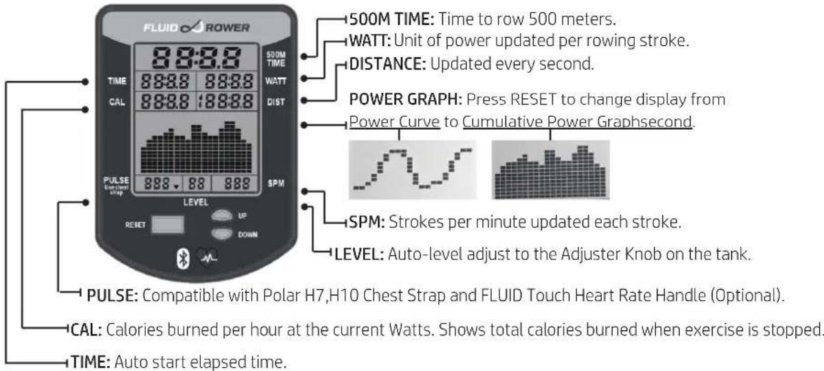
FLUID ROWER 500M TIME: Time to row 500 meters. WATT: Unit of power updated per rowing stroke. DISTANCE: Updated every second. POWER GRAPH: Press RESET to change display from Power Curve to Cumulative Power Graphsecond. SPM: Strokes per minute updated each stroke. LEVEL: Auto-level adjust to the Adjuster Knob on the tank. PULSE: Compatible with Polar H7,H10 Chest Strap and FLUID Touch Heart Rate Handle (Optional). CAL: Calories burned per hour at the current Watts. Shows total calories burned when exercise is stopped. TIME: Auto start elapsed time.WATT: Measures peak power in watts, calculating the strength and acceleration provided to accurately measure a user's power.
TRAINING DATA: Data gathered from each workout is displayed in a power curve and cumulative power graph, enabling real-time comparisons for effective progressive training.
AUTO ADJUST LEVEL: Built in potentiometer automatically adjusts the monitor's resistance level according to the position of the Adjuster Knob on the tank.
BLUETOOTH CONNECTIVITY: Each Rower is fitted with the most advanced Monitor technology, enabling Bluetooth connectivity with any compatible smart device. Designed to integrate with rowing and fitness apps, the Monitor will assist with effective training progression, capturing and comparing data for the competitive individual. Including FLUID Rowing APP available via FLUID Website. It is compatible with 3rd party APP and Software Update via Bluetooth.
NOTE: Heart Rate Chest Strap and Touch Heart Rate Handle is sold separately.
BATTERY WARNING: To prevent batteries from leaking, remove them from the Monitor if you plan on not using the equipment for more than 30 days.
WARNING: Heart rate monitoring systems may be inaccurate, Over exercising may result in serious injury or death. If you feel faint stop exercising immediately and seek professional medical advice.

Calibration Procedure
1) Press and hold Reset and Down for 5 seconds. Display will show "Level 1" Turn the Tank Handle to Level 1. Press Reset. Display will now show Level 2. Level 1 Calibration is complete.
2) Turn the Tank Handle to Level 2. Press Reset. Display will now show Level 3. Level 2 Calibration is complete.
3) Repeat for 3,4,5. Level 5 Press Reset. Calibration is complete.
(1)
flowchart
graph LR
    A["FLUID ROWER"] --> B["RESISTANCE"]
    B --> C["FLUID ROWER"]
    C --> D["RESISTANCE"]
    D --> E["FLUID ROWER"]

Monitor and APP Connectivity
text_image
FLUID CONNECT FLUID CONNECT- Download the "Fluid Connect" App on the [App store] or [Google Play].
- While the Monitor is ON, the Bluetooth will start scanning to link to the Phone/Pad.
- Turn on the FLUID CONNECT app in you phone.
- Push any work out icon, the APP will search the available Monitor near by.
- Choose the Monitor that you wish to link.
- After the Monitor link to the APP, the display of the Monitor will only show BT on the screen.

Bluetooth Heart Rate Pairing
NOTE: Heart Rate Chest Strap and Touch Heart Rate Handle is sold separately.
text_image
FLUID ROWER 0:00:00 TIME 0:00 0 CAL 0 0 PULSE 10.5 0 LEVEL RESET UP DOWN Heart RateThe Monitor will automatically pair with the nearest Bluetooth heart rate device.
When pairing is complete, the Monitor will begin to display the heart rate.

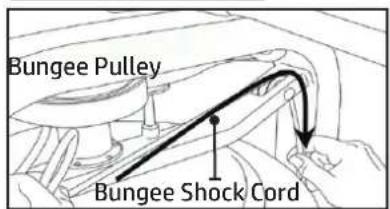
Detaching the Rower Belt
- To detach Belt, simply pull beyond the range of the normal rowing stroke until the Belt detaches from the Belt bungee pulley.
Tip: You'll hear the Velcro separating just before the Belt detaches.
text_image
Inner Clip Bungee Hook- Unhook the Bungee Shock Cord from the Rear Brace. Then, push out the Inner Clip from the Bungee Hook. Pull the Bungee through the Inner Clip until free. This will allow for the Bungee Shock Cord to be threaded completely out of the Main Frame and up to the Belt Bungee Pulley where it will be re-attached once the Rower Belt is in the proper position.
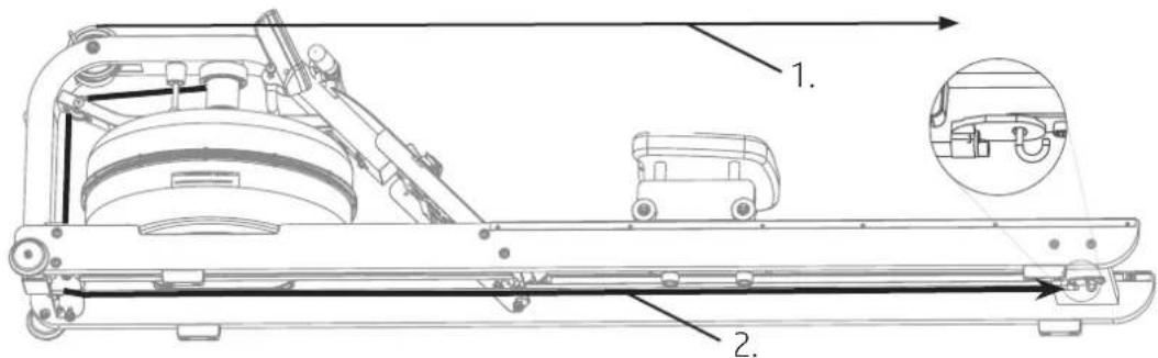
text_image
Technical diagram of a mechanical assembly with labeled parts and an inset detail view showing internal components.STEP 1
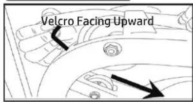
text_image
Velcro Facing UpwardBegin reattaching the Rower Belt by threading around the Rower Belt Pulley with the Velcro side facing upward as illustrated.
STEP 2
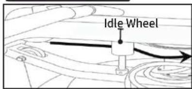
text_image
Idle WheelNext, thread the Belt around the Idle Wheel as shown. Once around the Idle Wheel, attach the Rower Belt to the Belt/Bungee Pulley. There is an obvious "lip" at the attachment point.
STEP 3
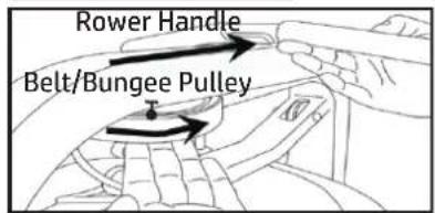
text_image
Rower Handle Belt/Bungee PulleyWind the Rower Belt onto the Belt/Bungee Pulley until the Rower Handle is as it's furthest forward position.
STEP 4
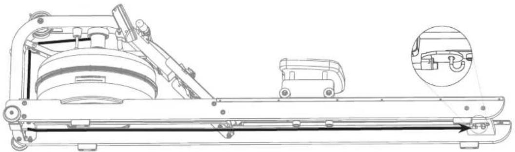
text_image
Bungee Pulley Bungee Shock CordRethread the Bungee Shock Cord (on opposite side of the Idle Wheel) back through the Bungee Pulleys and tie off at the Attachment Point.
STEP 5
Reattaching the Rower Belt
Recoil tension will decrease over time as the Bungee Shock Cord stretches. To increase recoil tension, simply push the Inner Clip out of the Bungee Hook from behind, pull the required amount of Bungee through the Inner Clip and replace the Inner Clip into the Bungee Hook as shown below.
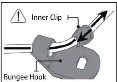
text_image
Inner Clip Bungee HookHint: Before reattaching the Inner Clip/Bungee Hook, tie a slip knot under slight tension at the Lower Bungee Pulley. This will keep the Bungee under tension while reassembling the Bungee Hook.
natural_image
Technical line drawing of a mechanical assembly with a zoomed-in inset showing a component detail (no text or symbols present)All preventive maintenance activities must be performed on a regular basis. Performing routine preventive maintenance actions can aid in providing safe, trouble-free operation of all Tunturi New Fitness BVequipment.
Tunturi New Fitness BVis not responsible for performing regular inspection and maintenance actions for your machines. Instruct all personnel in equipment inspection and maintenance actions and also in accident reporting and recording.

CAUTION Wipe and clean the Tank, Rails, and the Seat Wheels with clean water.
Do not use any chemical cleaner.
| Item | Time Frame Instructions | |
| Seat Rails and Wheels | Weekly Wipe down Side Rails | and Seat Wheels with lint free cloth. |
| Frame Weekly Wipe down | n Frame with lint free cloth. | |
| Tank Shell Weekly | Only use water and a clean cloth to wipe the Tank Shell.Do NOT use any chemical cleaner to wipe the Tank Shell | |
| Tank and Water Treatment | 12 months to 2 years | Follow instructions as specified in the “Water Treatment Procedure” section of this manual. |
| Bungee Cord | Check every hundred hours for correct tension and for signs of wear. | The Bungee Cord should last for many years. If a Bungee Cord change is required, please contact your local service representative or go online atwww.fluid-eu.comfor further details. |
| Rowing Belt | Check every hundred hours for correct tension and for signs of wear. | The Rowing Belt should provide many years of trouble free use.If a Rowing Belt change is required, please contact your local service representative or go online at www.fluid-eu.com for further details. |

Troubleshooting
| Fault Probable Cause Solution | ||
| Water changes color or becomes cloudy. | Rower is in direct sunlight or has not had water treatment. Local tap water is of poor quality. | Change Rower location to reduce direct exposure to sunlight. Add Water Treatment or change Tank water as directed in the Water Treatment section of this manual. Consider using distilled water to refill Tank. |
| Rower Belt slipping off Belt/ Bungee Pulley. | Bungee not under enough tension. Recoil not strong enough. | Tighten Bungee Cord following the instructions in "Reattaching the Rower Belt" section of this manual at "Step 5". |
| Inconsistent readings on the Monitor for 500meter split time and SPM (strokes per minute). | Sensor gap Faulty Sensor Sensor has moved out of position Wiring harness | Use the battery cover of the Monitor as a "Gap Tool" to check the gap between Sensor Head and Magnetic Ring, or see if the Sensor Head has moved out of position. Please contact your nearest FLUID customer service center for details. |
| The Monitor does not illuminate after battery installation. | Batteries installed incorrectly or need replacing. | Replace/reinstall batteries in correct position and try again. If the LCD screen fails to illuminate, try rotating the batteries slightly in the Monitor. If this fails, contact your local service center. |
| The Monitor screen illuminates, but does not register when rowing. | Loose or failed connection. Sensor gap too wide | Check that the Monitor lead is connected properly. If it is connected then contact your local service center. Check Sensor gap. |
| The Monitor LEVEL is not synchronized with the Tank LEVEL. | Monitor LEVEL needs to be recalibrated. | Please refer to "Calibration Procedure" page 13 of this manual. |

Install the Z Bracket onto the Storage Base.
Note: Do not tighten the Knob and the Bolt.
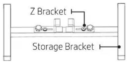
text_image
Z Bracket Storage BracketSTEP 2
Install the Bracket onto the Rower as shown.
natural_image
Technical line drawing of a mechanical assembly with no visible text or symbolsSTEP 3
Tighten the Z Bracket Knob to fix to the Rower.
Note: Ensure the Z Bracket is Under the middle crossbar secure
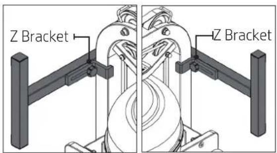
text_image
Z Bracket Z BracketSTEP 4
Stand the Rower up vertically with the main frame on the floor. Using the 8mm Allen Wrench tighten the Bolts.
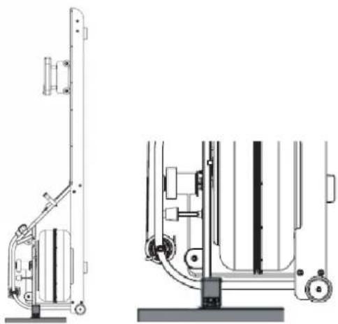
natural_image
Technical line drawing of a vertical mechanical device with side and top views (no text or symbols)HOME USE
Tunturi New Fitness BV Limited warrants that the R90W Rower, purchased from an authorized agent and in its undamaged original packaging, is free from defects in materials and workmanship. Tunturi New Fitness BV Limited or its agent will, at their discretion, repair or replace parts that become defective within the warranty period, subject to the specific inclusions and exclusions below.
Main Frame – 5 Year Limited Warranty
Tunturi New Fitness BV will repair or replace the Metal Main Frame of the Rower should it fail due to any defect in materials or workmanship within 5 years of the original purchase. Warranty does not apply to frame coating.
Polycarbonate Tank & Seals – 5 Year Limited Warranty
Tunturi New Fitness BV will repair or replace the polycarbonate Tank or seals should they fail due to any defect in materials or workmanship within 5 years of the original purchase.
Mechanical Components (of a non-wearing nature) - 2 Year Limited Warranty
Tunturi New Fitness BV will repair or replace any mechanical component should it fail due to any defect in materials or workmanship within 2 years of the original purchase.
Specific Inclusions
Seat Frame
Seat Rails
Shaft and Impeller Assembly
All Other Components (of a wearing nature) – 2 Year Limited Warranty
Tunturi New Fitness BV will repair or replace any component should it fail due to any defect in materials or workmanship within 2 year of the original purchase.
Specific Inclusions
Bungee Recoil Cord
Hand Grips & Footstraps
Polyester Rowing Belt
Seat and Seat Runners
All Pulleys, Rollers & Bearings
All rubber components
Monitor & Speed Sensor (excluding replaceable batteries)
Footplates (pivoting & sliding)
General Exclusions
Damage to the finish of any part of the machine
Damage due to neglect, abuse, incorrect assembly or use of the machine
Any charges for freight or customs clearance associated with the return or dispatch of parts
Any damage to or loss of goods during transport of any kind
Any labour cost associated with a warranty claim
General Conditions
- The serial number of the machine must be correctly registered with Tunturi New Fitness BV or one of its appointed distributors
• Tunturi New Fitness BV reserve the right to examine any part where replacement is claimed under warranty
• Warranty period applies only to the original purchaser from the date of purchase and is not transferable - The product must be returned to your place of purchase in original packaging with transportation, insurance and associated charges paid for by you and risk of loss or damage assumed by you
- Tunturi New Fitness BV makes no other warranties except as stated here and expressly disclaims all warranties not stated in this warranty. Neither Tunturi New Fitness BV nor its associates shall be responsible for incidental or consequential damages
- Manufacturer's warranty automatically commences upon sale of the product to end user or upon the expiration of one (1) year from month of manufacture, whichever occurs first
natural_image
Technical line drawing of a mechanical device with hoses and components (no text or symbols)
natural_image
Technical line drawing of two elongated metal brackets with mounting holes (no text or symbols)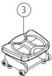
natural_image
Isometric line drawing of a mechanical device with labeled part (3), no text or symbols present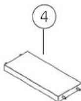

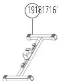
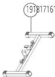
text_image
191817161SCHRITT 1
8 x M8 Stoppmutter [11]
8 x M8x45mm-Schraube [13]

CAUTION
Removing/Changing Tank Water

text_image
FLUID RESISTANCE 2 3 4 5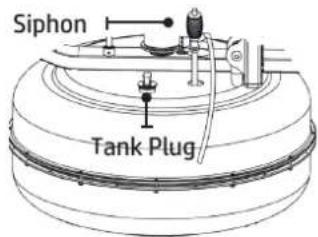
text_image
Siphon Tank Plugtext_image
Technical diagram of a mechanical assembly with labeled parts and an inset showing a close-up detail of the component.SCHRITT 1

text_image
Idle Wheeltext_image
Rower Handle Belt/Bungee Pulleynatural_image
Technical line drawing of a mechanical device with no visible text or symbols
Wartung
Storage Support Bracket Instructions
A Storage Support Bracket Kit for upright storage can be purchased separately.
SCHRITT 1
natural_image
Technical line drawing of a mechanical assembly with no visible text or symbolsSCHRITT 3
natural_image
Technical line drawing of a vertical mechanical device with side and top views (no text or symbols)HEIMGEBRAUCH
natural_image
Technical line drawing of a mechanical device with hoses and components (no text or symbols)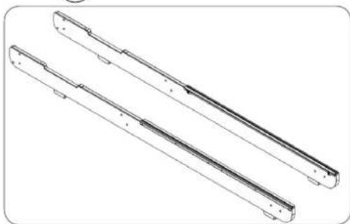
natural_image
Technical line drawing of two elongated metal brackets with mounting holes (no text or symbols)
natural_image
Technical line drawing of a mechanical device with labeled part (3), no readable text or symbols present.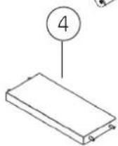


text_image
191817161STAP 1
text_image
Technical diagram of a mechanical assembly with labeled parts and an inset showing a close-up detail of the component.
natural_image
Technical line drawing of a mechanical assembly with no visible text or symbolsnatural_image
Technical line drawing of a mechanical assembly with no visible text or symbolsSTAP 3
natural_image
Technical line drawing of a mechanical device with front and side views (no text or symbols)
Internationale garantie
THUISGEBRUIK
natural_image
Technical line drawing of a mechanical device with no visible text or symbols
natural_image
Technical line drawing of two elongated metal brackets with mounting holes (no text or symbols)
natural_image
Technical line drawing of a mechanical device with labeled part (3), no readable text or symbols present.


text_image
191817161ÉTAPE 1
text_image
FLUSTRANCE QUALITY Calibration Level WARNING DO HOT BOSSED CAUSESION LEVEL Calibration Level WARNING DO HOT BOSSED CAUSESION LEVELtext_image
Mounting Pegs Footstrap Footplate Slider
text_image
Technical diagram of a mechanical assembly with labeled parts and an inset showing a close-up detail of the component.
natural_image
Technical line drawing of a mechanical assembly with a zoomed-in detail view (no text or symbols)natural_image
Technical line drawing of a mechanical assembly with no visible text or symbolsÉTAPE 3
natural_image
Technical line drawing of a vertical mechanical device with side and top views (no text or symbols)USAGE DOMESTIQUE
For customer support please visit
fluid-eu.com
TAIWAN
T: +886 3 478 3306
764 Chung Shan South Rd
Yangmei Taoyuan
Taiwan R.O.C.