STM405 - Wardrobe RYOBI - Free user manual and instructions
Find the device manual for free STM405 RYOBI in PDF.

| Type de produit | Storage cabinet |
| Marque | RYOBI |
| Modèle | STM405 |
| Capacité de poids maximale (montée sur rail mural LINK) | 54.4 kg (120 lbs) |
| Capacité de poids maximale (montée directement sur montants) | 90.7 kg (200 lbs) |
| Capacité de l'étagère intérieure | 27.2 kg (60 lbs) |
| Capacité du panneau inférieur (montage mural) | 63.5 kg (140 lbs) |
| Nombre de portes | 2 |
| Nombre d'étagères intérieures | 1 |
| Méthodes d'installation | On LINK wall track or directly on studs/concrete |
| Fixations incluses | M5 bolts (22), M5 nuts (22), M4 bolts (4), M4 nuts (4), mounting screws (4) |
| Accessoires inclus | Bumpers (2), shelf brackets (4), user manual |
| Utilisation prévue | Support for tools and products |
| Entretien | Keep dry, clean, free of oil or grease |
| Sécurité | Do not exceed the indicated loads; install on a solid structural support; do not use as a seat or ladder |
| Garantie | Limited lifetime warranty |
| Service client | 1-800-525-2579 or www.ryobitools.com |
Frequently Asked Questions - STM405 RYOBI
User questions about STM405 RYOBI
0 question about this device. Answer the ones you know or ask your own.
Ask a new question about this device
Download the instructions for your Wardrobe in PDF format for free! Find your manual STM405 - RYOBI and take your electronic device back in hand. On this page are published all the documents necessary for the use of your device. STM405 by RYOBI.
USER MANUAL STM405 RYOBI
EN MEXICO:
natural_image
Line drawing of a YOBI LNTX industrial control cabinet with no visible text or symbols on the main bodyTABLE OF CONTENTS
************************
■ General Safety Warnings ......2
■ Symbols.... 2-3
■ Features....3
■ Assembly 4-6
■ Installation 6-8
■ Parts Ordering and Service....Back page

WARNING:
To reduce the risk of injury, the user must read and understand the operator's manual before using this product.
SAVE THIS MANUAL FOR FUTURE REFERENCE
TABLE DES MATIÈRES
**********************************************************************
Read all safety warnings and all instructions. Failure to follow the warnings and instructions may result in electric shock, fire and/or serious injury.
READ ALL INSTRUCTIONS
- Know your product. Read operator's manual carefully. Learn its applications and limitations, as well as the specific potential hazards related to this product. Following this rule will reduce the risk of serious personal injury.
■ The maximum weight of all the items placed on this cabinet must not exceed 120 lbs. when mounted to the LINK wall rail and 200 lbs. when mounted directly to the wall studs. Evenly distribute the load when storing items.
■ Do not exceed the maximum weight capacity for the shelves.
This is a cabinet. Do not use for any other purpose than supporting tools or products. Do not use as a seat, ladder, or standing platform.
- Keep the area around the cabinet clean and well lit. Cluttered or dark areas invite accidents.
■ Mount the cabinet in a dry, indoor place protected from wet conditions.
- Keep cabinet dry, clean, and free from oil and grease.
- Do not use the cabinet if it is damaged or broken. A damaged or broken cabinet may not mount securely and/or it might not provide adequate support for the items stored on it.
■ When servicing this product, use only identical replacement parts. Use of unauthorized parts may create a risk of injury.
■ Mount the cabinets to sound structural supports. NEVER mount the cabinets to drywall or plaster without the mounting fastener going into a structural support. ALWAYS use concrete anchors when installing cabinets into concrete, brick, or other masonry. Failure to properly mount the cabinet could result in a falling hazard that can cause death or serious personal injury.
■ Mount the cabinet on smooth and flat surfaces capable of bearing the weight of cabinet and the items stored on it.
■ Use extra care when mounting the unit. Keep proper footing and balance at all times.
■ Ensure the cabinet is securely mounted. Make sure it does not rock, slide, or move before storing products or tools.
■ Always wear eye protection with side shields marked to comply with ANSI Z87.1 during installation. Following this rule will reduce the risk of serious personal injury.
■ Do not allow children or untrained individuals to use this cabinet.
■ Always get help when lifting, moving, and mounting the cabinet. When lifting, hold the cabinet close to your body. Bend your knees so you can lift with your legs, not your back.
■ SAVE THESE INSTRUCTIONS. Refer to them frequently and use them to instruct other users. If you loan someone this product, also loan these instructions.
SYMBOLS
| The following signal words and meanings are intended to explain the levels of risk associated with this product. SYMBOL SIGNAL MEANING | ||
 | DANGER: | Indicates a hazardous situation, which, if not avoided, will result in death or serious injury. |
 | WARNING: | Indicates a hazardous situation, which, if not avoided, could result in death or serious injury. |
 | CAUTION: | Indicates a hazardous situation, that, if not avoided, may result in minor or moderate injury. |
| NOTICE: | (Without Safety Alert Symbol) Indicates information considered important, but not related to a potential injury (e.g. messages relating to property damage). | |
SYMBOLS
| Some of the following symbols may be used on this product. Please study them and learn their meaning. Proper interpretation of these symbols will allow you to operate the product better and safer. SYMBOL NAME DESIGNATION/EXPLANATION | ||
 | Safety Alert Indicates | a potential personal injury hazard. |
 | Read Operator's Manual | To reduce the risk of injury, user must read and understand operator's manual before using this product. |
 | Eye Protection | Always wear eye protection with side shields marked to comply with ANSI Z87.1. |
FEATURES
PRODUCT SPECIFICATIONS
See Figure 1.
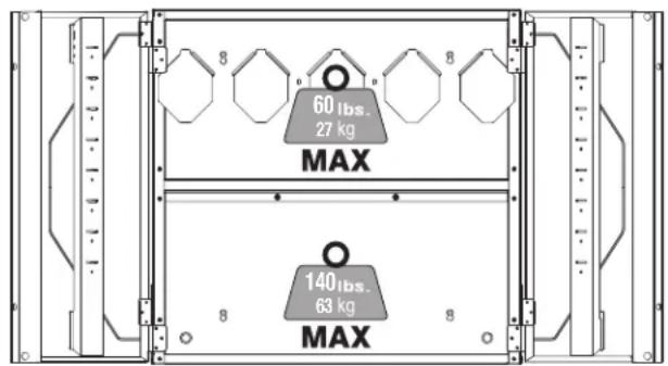
Maximum Weight Capacity
LINK wall rail mounted configuration
Interior shelf....60 lbs
Bottom panel....60 lbs
Stud mounted configuration
Interior shelf....60 lbs
Bottom panel....140 lbs
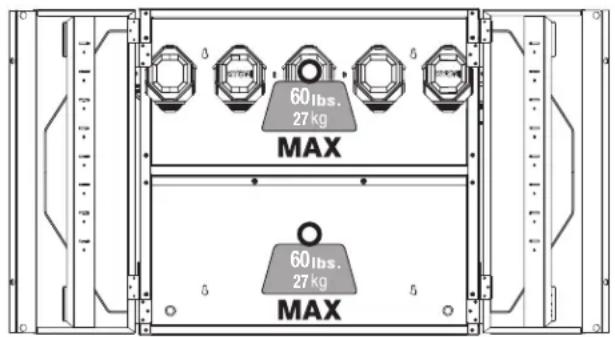
LINK WALL RAIL MOUNTED
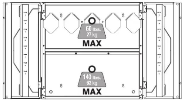
STUD MOUNTED
Fig. 1
ASSEMBLY
UNPACKING
This product requires assembly.
■ Carefully remove the product and any accessories from the box. Make sure that all items listed in the packing list are included.

WARNING:
Do not use this product if any parts on the Packing List are already assembled to your product when you unpack it. Parts on this list are not assembled to the product by the manufacturer and require customer installation. Use of a product that may have been improperly assembled could result in serious personal injury.
■ Inspect the product carefully to make sure no breakage or damage occurred during shipping.
■ Do not discard the packing material until you have carefully inspected and satisfactorily operated the product.
■ If any parts are damaged or missing, please call 1-800-525-2579 for assistance.
PACKING LIST
Top Panel Bumpers (2)
Bottom Panel M5 Bolts (22, 2 additional)
Side Panels (2) M5 Nuts (22, 2 additional)
Back Panels (2) M4 Bolts (4, 2 additional)
Doors (2) M4 Nuts (4, 2 additional)
Interior Shelf Mounting Screws (4)
Shelf Clips (4) Operator's Manual

WARNING:
If any parts are damaged or missing do not operate this product until the parts are replaced. Use of this product with damaged or missing parts could result in serious personal injury.

WARNING:
Do not attempt to modify this product or create accessories not recommended for use with this product. Any such alteration or modification is misuse and could result in a hazardous condition leading to possible serious personal injury.
ASSEMBLING THE CABINET
See Figures 2 - 9.
■ Align holes in top panel and upper back panel as shown in Figure 2.
NOTE: Octagonal bends should face inward toward the interior of the cabinet.
■ Insert M5 bolts (2) through the two centered back holes of the panels as shown in Figure 2. Secure with M5 nuts (2).
NOTE: M5 bolts and nuts should only be used to secure the side and back facing panels of the cabinet. M4 bolts and nuts should only be used to secure the front facing corners of the cabinet.
■ Align holes in top panel and right side panel as shown in Figure 3.
NOTE: Side panel tabs fit around outside of top panel. The upper back panel edges will fit inside the side panel.
■ Insert M5 bolts (4) through the side hole and back holes of the panels as shown in Figure 3. Secure with M5 nuts (4).
■ Repeat steps above to attach the left side panel.
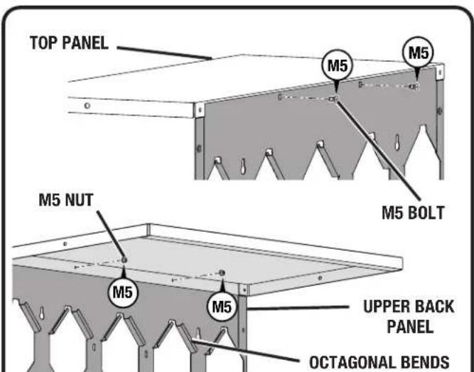
Fig. 2
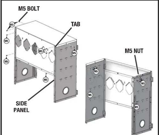
Fig. 3
ASSEMBLY
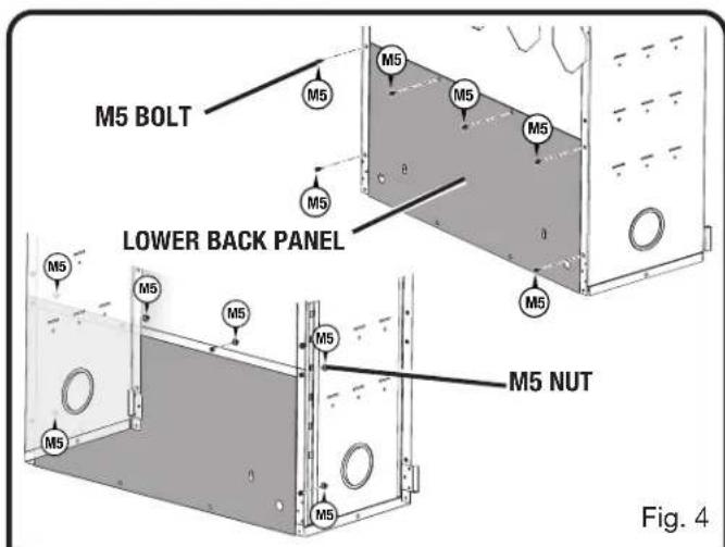
■ Slide lower back panel up between side panels until top edge moves behind lip of upper back panel as shown in Figure 4.
NOTE: The lip of the upper back panel should be on the interior side of the cabinet.
■ Insert M5 bolts (6) through the back holes of the panels as shown in Figure 4. Secure with M5 nuts (6).
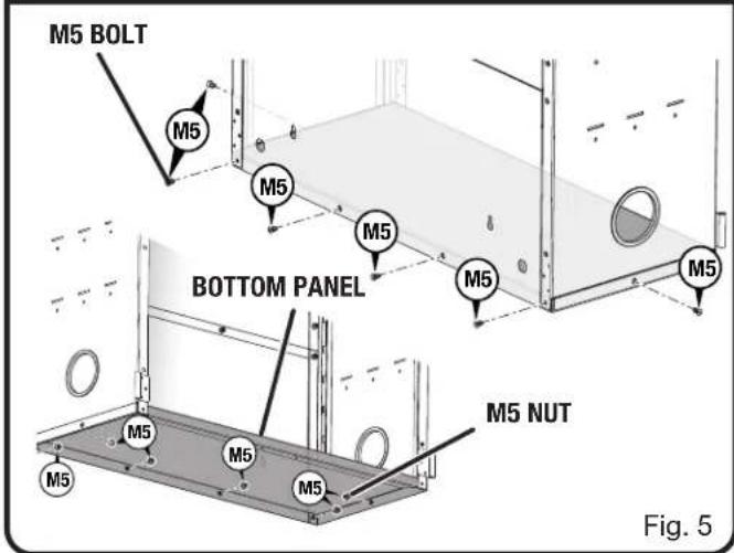
■ Align holes in bottom panel with holes in lower back and side panels as shown in Figure 5.
NOTE: The flat surface of the bottom panel should face upward, toward the interior of the cabinet.
■ Insert M5 bolts (6) through the side holes and back holes of the bottom panel as shown in Figure 5. Secure with M5 nuts (6).
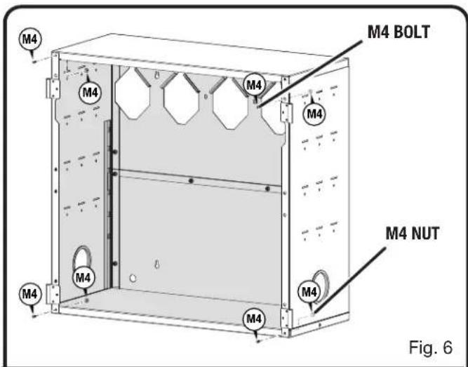
■ Insert M4 bolts (4) through the front facing corner holes of the cabinet as shown in Figure 6. Secure with M4 nuts (4).
NOTE: M5 bolts and nuts should only be used to secure the side and back facing panels of the cabinet. M4 bolts and nuts should only be used to secure the front facing corners of the cabinet.
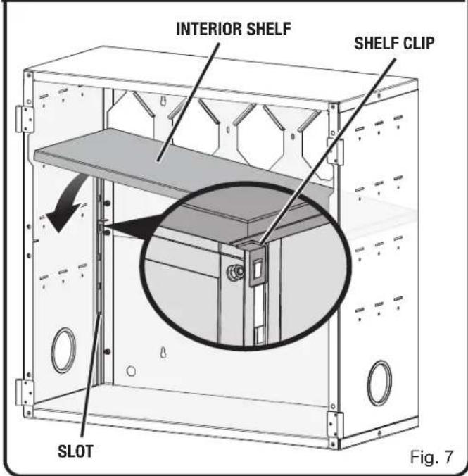
■ Insert shelf clips (4) into slots in the interior of the cabinet as shown in Figure 7. Make sure shelf clips are all on the same level.
■ Insert interior shelf into cabinet by tilting shelf diagonally and placing onto shelf clips.
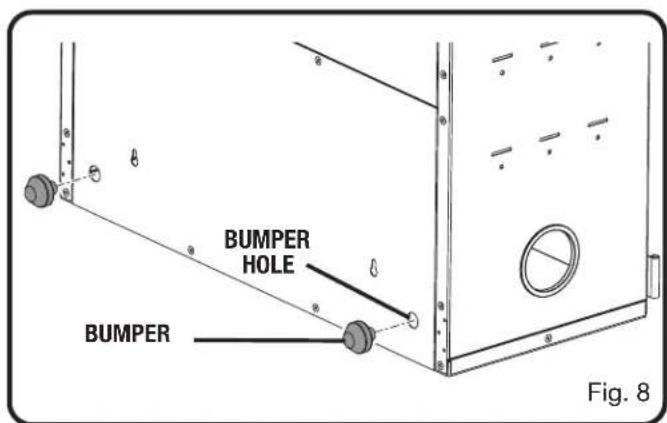
If mounting onto a wall rail, insert bumpers (2) into round holes on the bottom back panel of the cabinet as shown in Figure 8.
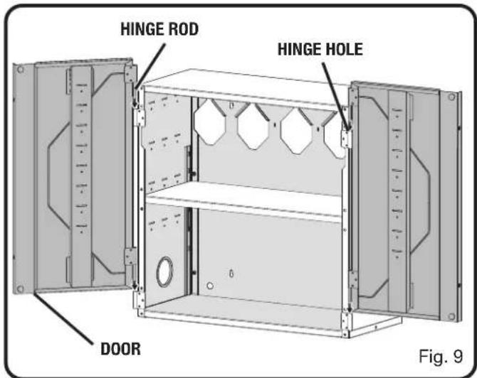
■ Install cabinet doors by inserting hinge rod through the hinge hole as shown in Figure 9.
NOTE: For ease of installation, doors can be installed after mounting cabinet onto LINK wall rail or wall stud. See Installation section.
ASSEMBLY
INSTALLATION

WARNING:
To reduce the risk of injury, do not attempt to use this product until you have read thoroughly and understand completely this operator's manual and the operator's manual for any power tools used.
TOOLS NEEDED (NOT INCLUDED)
For mounting onto LINK wall rail:
Phillips Screwdriver, #10 Screws (optional)
For mounting onto wall studs or concrete:
Drill, Hammer, Level, Pencil, Phillips Screwdriver, Concrete Anchors (if mounting onto concrete)
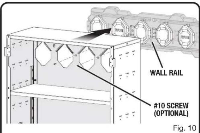
MOUNTING THE CABINET ONTO LINK WALL RAIL
See Figure 10.

WARNING:
Only install screws into sound structural supports (such as studs and concrete) in areas where no electrical wires, utility cables, pipes, or other obstructions are located. Failure to follow these instructions can result in death, electrical shock, or other serious personal injury.

WARNING:
Do not lift the product without help. Hold it close to your body. Keep your knees bent and lift with your legs, not your back. Ignoring these precautions can result in back injury.
■ Mount the wall rail as described in the rail's Operator's Manual.
■ Insert bumpers (2) into holes on the bottom back panel of the cabinet if not already installed.
■ For ease of installation, remove doors from cabinet before mounting onto LINK wall rail.
■ With the help of at least one other person, carefully lift the cabinet and position the cabinet onto five of the raised octagonal patterns on the wall rail.
NOTE: Cabinet cannot be installed over two parallel rails.
■ IMPORTANT! To ensure the cabinet is seated properly, check that the holes through the back wall of the cabinet are lined up with the corresponding holes in the LINK wall rail.
If desired, insert #10 screws (not included) into these holes in the back wall of the cabinet and into the holes in the LINK wall rail for extra support.
■ Install cabinet doors by inserting hinge rod through the hinge hole.
To unmount the cabinet:
■ Remove all of the items stored in the cabinet.
■ Remove the #10 screws (if installed) from the cabinet.
■ With the help of at least one other person, carefully pull the cabinet away from the wall rail.
INSTALLATION
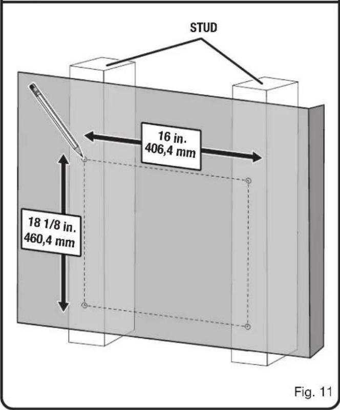
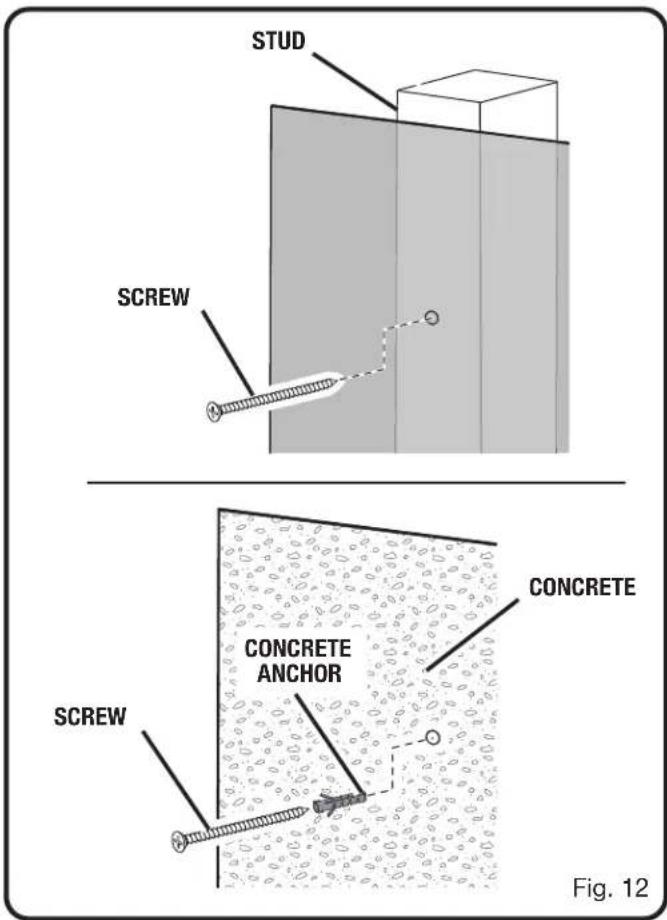
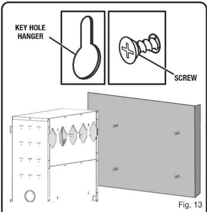
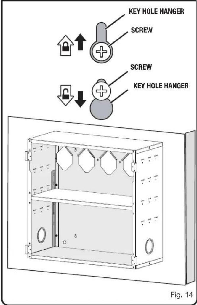
MOUNTING THE CABINET ONTO THE WALL STUDS OR CONCRETE
See Figures 11 - 14.

WARNING:
Only install screws and anchors into sound structural supports (such as studs and concrete) in areas where no electrical wires, utility cables, pipes, or other obstructions are located. Failure to follow these instructions can result in death, electrical shock, or other serious personal injury.

WARNING:
Do not lift the product without help. Hold it close to your body. Keep your knees bent and lift with your legs, not your back. Ignoring these precautions can result in back injury.
- Locate the wooden studs behind your wall.
■ Using a pencil and a level, mark four screw holes. The top two screw holes should be 16 in. apart on studs. The bottom screw holes should be 18 1/8 in. below the top screws.
■ Using an AC or DC drill make four pilot holes slightly smaller than the screws.
■ Using a Phillips screwdriver install the screws through each of the pilot holes. Leave the head of the screw approximately 1/4 in. off the wall.
NOTE: Use screws and concrete anchors (not included) when installing the cabinet into concrete. Use your fingers to press the anchor into the pilot hole. Tap the head of the anchor lightly with the hammer until it is flush with the wall. Then install the screws.
■ For ease of installation, remove doors from cabinet before mounting onto wall studs.
■ With the help of at least one other person, carefully lift the cabinet and align the keyholes on the back with the screws in the walls.
■ Place the wide portion of each keyhole over the head of each screw.
■ To lock the cabinet in place, slide the cabinet down until the screws are inside the narrow portions of each keyhole.
■ Tighten screws until snug.
NOTE: Check cabinet installation by verifying it is level, plumb, and secure to the wall.
■ Install cabinet doors by inserting hinge rod through the hinge hole.
To unmount the cabinet:
■ Remove all of the items stored on the cabinet.
■ With the help of at least one other person, carefully lift the cabinet until the screws are inside the wide portions of each keyhole and remove the cabinet from the wall.
INSTALLATION
AVERTISSEMENTS DE SÉCURITÉ GÉNÉRALES

AVERTISSEMENT :
MONTÉE SUR RAIL MURAL LINK
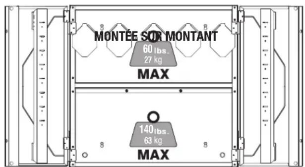
Fig. 1
ASSEMBLAGE
DÉBALLAGE
Estante interior 27,2 kg (60 lbs)
Panel inferior 27,2 kg (60 lbs)
MONTAJE EN RIEL DE PARED LINK
MONTAJE EN MONTANTES
Fig. 1
ARMADO
DESEMPAQUETADO
Panel superior Topes (2)
Panel inferior Pernos M5 (22, 2 adicional)
Paneles lateral (2) Tuercas M5 (22, 2 adicional)
Paneles trasero (2) Pernos M4 (4, 2 adicional)
Puertas (2) Tuercas M4 (4, 2 adicional)
To request service, purchase replacement parts,
locate an Authorized Service Center or obtain Customer or Technical Support:
Visit www.ryobitools.com or call 1-800-525-2579
If any parts or accessories are damaged or missing, do not return this product to the store.
Call 1-800-525-2579 for immediate service.
Please obtain your model and serial number from the product data plate.
This product is covered under a Limited Lifetime Warranty. Proof of purchase is required.
MODEL NUMBER* ____ SERIAL NUMBER ____
*Model number on product may have additional letters at the end. These letters designate
manufacturing information and should be provided when calling for service.
RYOBI is a trademark of Ryobi Limited and is used pursuant to a license granted by Ryobi Limited.