
RMX001 - Cement mixer RYOBI - Free user manual and instructions
Find the device manual for free RMX001 RYOBI in PDF.

| Product Type | Cement Mixer |
| Brand | RYOBI |
| Model | RMX001 |
| Use | Mixing stucco, cement, mortar, aggregates |
| Motor | 1/2 HP, 120 V~, 60 Hz, 5.3 A |
| No-Load Speed | 25 rpm |
| Drum Size | 0.14 m³ (5 ft³) |
| Max. Fill Capacity | 122.5 kg (270 lb) / 0.07 m³ (2.5 ft³) |
| Mixing Paddles | 2 paddles (558.8 mm long) |
| Wheel Type | Heavy-duty rubber wheels |
| Weight | Approx. 68 kg (150 lb) (estimate) |
| Power Supply | 120 V~, 60 Hz, AC only |
| Protection | Circuit breaker with reset button |
| Grounding | Plug with grounding pin, mandatory use |
| Cord Length | Not specified |
| Switch | On/Off at rear of motor |
| Drum Rotation | 360° pivot around frame |
| Opening Adjustment | Adjustable height via locking handle |
| Drum Material | Heavy-duty steel |
| Maintenance | Clean with water after use; lubrication not required |
| Warranty | 3 years (limited) |
| Support | 1-800-525-2579 (United States) |
Frequently Asked Questions - RMX001 RYOBI
User questions about RMX001 RYOBI
0 question about this device. Answer the ones you know or ask your own.
Ask a new question about this device
Download the instructions for your Cement mixer in PDF format for free! Find your manual RMX001 - RYOBI and take your electronic device back in hand. On this page are published all the documents necessary for the use of your device. RMX001 by RYOBI.
USER MANUAL RMX001 RYOBI
natural_image
Line drawing of a mechanical device with wheels and a circular housing (no text or symbols)
REGISTER YOUR TOOLS
http://register.ryobitools.com
1-800-525-2579
TABLE OF CONTENTS
**********************************************************************
■ General Power Tool Safety Warnings....2-3
■ Concrete Mixer Safety Instructions .... 3-4
■ Symbols....5
■ Electrical....6-7
■ Features....8
■ Tools Needed ....9
■ Loose Parts List....9
■ Assembly 10-13
■ Operation.... 14-18
■ Maintenance....18
■ Troubleshooting ....19
■ Parts Ordering / Service.....Back Page

WARNING: To reduce the
risk of injury, the user must read and understand the operator's manual before using this product.
SAVE THIS MANUAL FOR FUTURE REFERENCE
TABLE DES MATIÈRES
**********************************************************************
Read all safety warnings, instructions, illustrations, and specifications provided with this power tool. Failure to follow all instructions listed below may result in electric shock, fire and/or serious injury.
Save all warnings and instructions for future reference.
The term “power tool” in the warnings refers to your mains-operated (corded) power tool or battery-operated (cordless) power tool.
WORK AREA SAFETY
- Keep work area clean and well lit. Cluttered or dark areas invite accidents.
- Do not operate power tools in explosive atmospheres, such as in the presence of flammable liquids, gases, or dust. Power tools create sparks which may ignite the dust or fumes.
- Keep children and bystanders away while operating a power tool. Distractions can cause you to lose control.
ELECTRICAL SAFETY
■ Power tool plugs must match the outlet. Never modify the plug in any way. Do not use any adapter plugs with earthed (grounded) power tools. Unmodified plugs and matching outlets will reduce risk of electric shock.
■ Avoid body contact with earthed or grounded surfaces, such as pipes, radiators, ranges and refrigerators. There is an increased risk of electric shock if your body is earthed or grounded.
■ Do not expose power tools to rain or wet conditions. Water entering a power tool will increase the risk of electric shock.
- Do not abuse the cord. Never use the cord for carrying, pulling or unplugging the power tool. Keep cord away from heat, oil, sharp edges or moving parts. Damaged or entangled cords increase the risk of electric shock.
■ When operating a power tool outdoors, use an extension cord suitable for outdoor use. Use of a cord suitable for outdoor use reduces the risk of electric shock.
If operating a power tool in a damp location is unavoidable, use a ground fault circuit interrupter (GFCI) protected supply. Use of a GFCI reduces the risk of electric shock.
PERSONAL SAFETY
■ Stay alert, watch what you are doing and use common sense when operating a power tool. Do not use a power tool while you are tired or under the influence of drugs, alcohol or medication. A moment of inattention while operating power tools may result in serious personal injury.
■ Use personal protective equipment. Always wear eye protection. Protective equipment such as dust mask, non-skid safety shoes, hard hat, or hearing protection used for appropriate conditions will reduce personal injuries.
■ Prevent unintentional starting. Ensure the switch is in the off-position before connecting to power source and/or battery pack, picking up or carrying the tool. Carrying power tools with your finger on the switch or energising power tools that have the switch on invites accidents.
■ Do not overreach. Keep proper footing and balance at all times. This enables better control of the power tool in unexpected situations.
■ Dress properly. Do not wear loose clothing or jewelry. Keep your hair and clothing away from moving parts. Loose clothes, jewelry, or long hair can be caught in moving parts.
■ Do not let familiarity gained from frequent use of tools allow you to become complacent and ignore tool safety principles. A careless action can cause severe injury within a fraction of a second.
■ Do not wear loose clothing or jewelry. Contain long hair. Loose clothes, jewelry, or long hair can be drawn into air vents.
- Do not force the power tool. Use the correct power tool for your application. The correct power tool will do the job better and safer at the rate for which it was designed.
- Do not use the power tool if the switch does not turn it on and off. Any power tool that cannot be controlled with the switch is dangerous and must be repaired.
■ Disconnect the plug from the power source and/or remove the battery pack, if detachable, from the
POWER TOOL USE AND CARE
GENERAL POWER TOOL SAFETY WARNINGS
power tool before making any adjustments, changing accessories, or storing power tools. Such preventive safety measures reduce the risk of starting the power tool accidentally.
■ Store idle power tools out of the reach of children and do not allow persons unfamiliar with the power tool or these instructions to operate the power tool. Power tools are dangerous in the hands of untrained users.
- Maintain power tools and accessories. Check for misalignment or binding of moving parts, breakage of parts and any other condition that may affect the power tool's operation. If damaged, have the power tool repaired before use. Many accidents are caused by poorly maintained power tools.
■ Use the power tool, accessories and tool bits etc. in accordance with these instructions, taking into account the working conditions and the work to be performed. Use of the power tool for operations different from those intended could result in a hazardous situation.
- Keep handles and grasping surfaces dry, clean and free from oil and grease. Slippery handles and grasping surfaces do not allow for safe handling and control of the tool in unexpected situations.
SERVICE
■ Have your power tool serviced by a qualified repair person using only identical replacement parts. This will ensure that the safety of the power tool is maintained.
CONCRETE MIXER SAFETY INSTRUCTIONS
- Know your power tool. Read operator's manual carefully. Learn its applications and limitations, as well as the specific potential hazards related to this tool. Following this rule will reduce the risk of electric shock, fire, or serious injury.
■ Always wear eye protection with side shields marked to comply with ANSI Z87.1. Failure to do so could result in materials being thrown into your eyes, resulting in possible serious injury.
■ Protect your lungs. Wear a face or dust mask if the operation is dusty. Following this rule will reduce the risk of serious personal injury. - Keep the cord away from the working area. The cord may be entangled by the drum.
■ To reduce the risk of electrical shock, do not put the mixer in water or other liquid. Do not place or store appliance where it can fall or be pulled into water.
■ Never stand on the tool. Serious injury could occur if the tool is tipped or if you accidentally contact any moving parts.
■ Do not contact moving parts. - Do not reach into the drum with your hands or insert any other objects including trowels and shovels into it while mixing. Contact with the tines or substances inside the drum may lead to serious personal injury.
■ Do not use this tool to mix flammable or explosive materials. Fire or explosion can cause severe burns or death.
■ Do not mix food. Power tools and their accessories are not designed for processing food.
■ Follow the instructions and warnings for the material to be mixed. Material to be mixed may be harmful.
■ Only use attachments recommended or sold by the manufacturer.
■ Always get help if you need to lift the tool. When lifting, hold the tool close to your body. Bend your knees so you can lift with your legs, not your back.
■ When moving the tool or adjusting the positon of the drum, hold the tool with both hands at the intended handles. Loss of control can cause personal injury.
■ Before moving the tool, empty the drum and disconnect the power supply.
- Put the tool on a firm level surface where there is plenty of room to make adjustments and properly operate the tool.
■ Make sure all adjustments are secure and the work area is clear of tools and other obstructions before operating the tool.
CONCRETE MIXER SAFETY INSTRUCTIONS
■ Turn on the motor prior to filling the concrete mixer. Following this rule will help substances mix evenly, prevent motor damage, and help extend the life of the tool.
Always keep the drum's opening in view when filling or emptying the tool. Certain mixing substances can harden quickly and could cause property damage or personal injury if spilled.
■ Do not exceed the batch capacity of this tool. Overfilling the drum could damage the motor.
■ Inspect tool cords periodically and, if damaged, have repaired at your nearest authorized service center. Constantly stay aware of cord location. Following this rule will reduce the risk of electric shock or fire.
- Check damaged parts. Before further use of the tool, a guard or other part that is damaged should be carefully checked to determine that it will operate properly and perform its intended function. Check for alignment of moving parts, binding of moving parts, breakage of parts, mounting, and any other conditions that may affect its operation. A guard or other part that is damaged should be properly repaired or replaced by an authorized service center. Following this rule will reduce the risk of shock, fire or serious injury.
■ Make sure your extension cord is in good condition. When using an extension cord, be sure to use one
heavy enough to carry the current your product will draw. A wire gauge size (A.W.G.) of at least 14 is recommended for an extension cord 50 feet or less in length. A cord exceeding 100 feet is not recommended. If in doubt, use the next heavier gauge. The smaller the gauge number, the heavier the cord. An undersized cord will cause a drop in line voltage resulting in loss of power and overheating.
If the power supply cord is damaged, it must be replaced only by the manufacturer or by an authorized service center to avoid risk.
■ Never leave tool running unattended. Unplug tool when leaving work area or when tool is out of your line of sight.
■ Empty and clean the drum prior to transporting the tool away from the work area or storing the tool for long periods of time.
■ Clean and dry the tool after each use.
■ Dispose of concrete, rinse water, and other substances in areas designated for that purpose. Local, state or federal laws may prohibit disposal of these materials in storm drains, roadsides, landfills or other locations. Consult your local waste authority for information regarding available disposal options.
■ This product is not designed to be towed behind a vehicle.
SYMBOLS
| The following signal words and meanings are intended to explain the levels of risk associated with this product. | ||
| SYMBOL | SIGNAL | MEANING |
 | DANGER: | Indicates a hazardous situation, which, if not avoided, will result in death or serious injury. |
 | WARNING: | Indicates a hazardous situation, which, if not avoided, could result in death or serious injury. |
 | CAUTION: | Indicates a hazardous situation, that, if not avoided, may result in minor or moderate injury. |
| NOTICE: | (Without Safety Alert Symbol) Indicates information considered important, but not related to a potential injury (e.g. messages relating to property damage). | |
| Some of the following symbols may be used on this product. Please study them and learn their meaning. Proper interpretation of these symbols will allow you to operate the product better and safer. SYMBOL NAME DESIGNATION/EXPLANATION | ||
 | Safety Alert Indicates a potential | personal injury hazard. |
 | Read Operator's Manual | To reduce the risk of injury, user must read and understand operator's manual before using this product. |
 | Eye and Breathing Protection | Always wear eye protection with side shields marked to comply with ANSI Z87.1 along with breathing protection when operating this equipment. |
 | Wet Conditions Alert Do not expose to rain or use in damp locations. | |
 | Entanglement Hazard | Risk of loose clothing, long hair, and body parts being drawn into spinning drum. |
 | Pinch Point Always watch for potential areas where pinching could occur. | |
 | Electrocution Failure to properly ground can result in electrocution. | |
| V Volts Voltage | ||
| A Amperes Current | ||
| Hz Hertz Frequency (cycles per second) | ||
| min Minutes Time | ||
| ~ | Alternating Current | Type of current |
| no | No Load Speed | Rotational speed, at no load |
| .../min | Per Minute | Revolutions, strokes, surface speed, orbits etc., per minute |
ELECTRICAL
EXTENSION CORDS
Use only 3-wire extension cords that have 3-prong grounding plugs and 3-pole receptacles that accept the tool's plug. When using a power tool at a considerable distance from the power source, use an extension cord heavy enough to carry the current that the tool will draw. An undersized extension cord will cause a drop in line voltage, resulting in a loss of power and causing the motor to overheat. Use the chart provided below to determine the minimum wire size required in an extension cord. Only round jacketed cords listed by Underwriter's Laboratories (UL) should be used.
**Ampere rating (on tool data plate)
0-2.0 2.1-3.4 3.5-5.0 5.1-7.0 7.1-12.0 12.1-16.0
Cord Length Wire Size (A.W.G.)
| 25' | 16 | 16 | 16 | 16 | 14 | |
| 50' | 16 | 16 | 16 | 14 | 14 | |
| 100' | 16 | 16 | 14 | 12 | 10 | — |
**Used on 12 gauge - 20 amp circuit.
NOTE: AWG = American Wire Gauge
Always use an extension cord that is designed for outside use. This is indicated by the letters "W-A" or "W" on the cord's jacket.
Before using an extension cord, inspect it for loose or exposed wires and cut or worn insulation.
Use only extension cords that are intended for outdoor use. These extension cords are identified by a marking “Acceptable for use with outdoor appliances; store indoors while not in use”. Use only extension cords having an electrical rating not less than the rating of the product. Do not use damaged extension cords. Examine extension cord before using and replace if damaged. Do not abuse extension cords and do not yank on any cord to disconnect. Keep cord away from heat and sharp edges. Always disconnect the extension cord from the receptacle before disconnecting the product from the extension cord.

WARNING:
Keep the extension cord clear of the working area. Position the cord so that it will not come in contact with the drum or mixing materials while you are using the mixer. Failure to do so can result in serious personal injury.

WARNING:
Check extension cords before each use. If damaged replace immediately. Never use tool with a damaged cord since touching the damaged area could cause electrical shock resulting in serious injury.
ELECTRICAL CONNECTION
This tool is powered by a precision built electric motor. It should be connected to a power supply that is 120 V, AC only (normal household current), 60 Hz. Do not operate this tool on direct current (DC). A substantial voltage drop will cause a loss of power and the motor will overheat. If the tool does not operate when plugged into an outlet, double check the power supply.
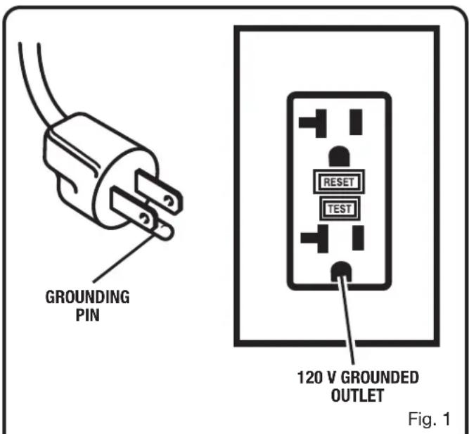
GROUNDING INSTRUCTIONS
See Figure 1.
This product must be grounded. In the event of a malfunction or breakdown, grounding provides a path of least resistance for electric current to reduce the risk of electric shock. This tool is equipped with an electric cord having an equipment-grounding conductor and a grounding plug. The plug must be plugged into a matching outlet that is properly installed and grounded in accordance with all local codes and ordinances.
Do not modify the plug provided. If it will not fit the outlet, have the proper outlet installed by a qualified electrician.

WARNING:
Improper installation of the grounding plug is able to result in a risk of electric shock. When repair or replacement of the cord is required, do not connect the grounding wire to either flat blade terminal. The wire with insulation having an outer surface that is green with or without yellow stripes is the grounding wire.
Check with a qualified electrician or service personnel if the grounding instructions are not completely understood, or if in doubt as to whether the tool is properly grounded.
Repair or replace a damaged or worn cord immediately.
ELECTRICAL
This product is for use on a nominal 120 volt circuit and has a grounding plug similar to the plug illustrated in Figure 1. Only connect the product to an outlet having the same configuration as the plug. Do not use an adapter with this product.
Ground Fault Circuit Interrupter (GFCI) protection should be provided on the circuit(s) or outlet(s) to be used for the tool. Outlets are available having built-in GFCI protection and may be used for this measure of safety.
If the tool is used with an extension cord, ensure the connection of the tool's power cord and the extension cord are not on the ground. Auxiliary devices should always be plugged into the wall outlet and not at the connection of an extension cord and the power tools' power cord.
If a protected outlet is not available, do not use the tool until an outlet can be changed or auxiliary protection can be obtained. These auxiliary protection devices are available at your local retailer.
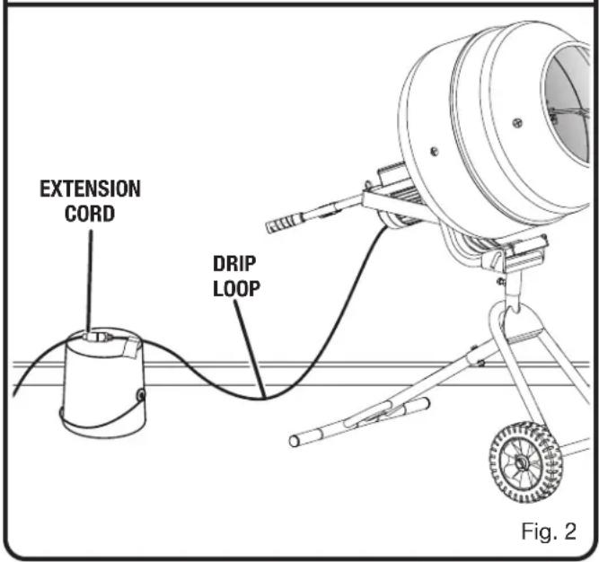
To avoid the possibility of the tool plug or outlet getting wet, position mixer to one side of a wall-mounted outlet to prevent water from dripping onto the outlet or plug. The operator should arrange a “drip loop” in the cord connecting the mixer to the outlet. The “drip loop” is that part of the cord below the level of the outlet or the connector if an extension cord is used, to prevent water traveling along the cord and coming in contact with the outlet.
If the plug or outlet does get wet, DO NOT unplug the cord. Disconnect the fuse or circuit breaker that supplies power to the tool then unplug and examine for the presence of water in the outlet.

WARNING:
To reduce the risk of electrocution, keep all connections dry and off the ground. Do not touch the plug with wet hands.
FEATURES
PRODUCT SPECIFICATIONS
Drum Size....5 cu. ft
Maximum Batch Capacity....270 lbs. (2.5 cu. ft)
Motor....1/2 HP
Rating 120 V\~, 60 Hz, AC only, 5.3 Amps
No Load Speed 25 r/min (RPM)
Mixing Tines .......Two (22 in. long)
KNOW YOUR CONCRETE MIXER
See Figure 3.
The safe use of this product requires an understanding of the information on the tool and in this operator's manual as well as a knowledge of the project you are attempting. Before use of this product, familiarize yourself with all operating features and safety rules.
DRUM - The heavy duty steel drum can be pivoted up or down depending on your application. It is 5 cu. ft. and spins at 25 rpm.
HANDLES - The mixer has convenient handles located on left and right side for adjusting the angle of the drum as well as moving the mixer.
MIXING TINES - The mixing tines are designed to mix thick and heavy materials.
MOTOR - This machine has a strong motor with sufficient power to mix up 270 lbs. of cement.
NOTICE:
Do not exceed the batch capacity of this tool. Overfilling the drum could damage the motor.
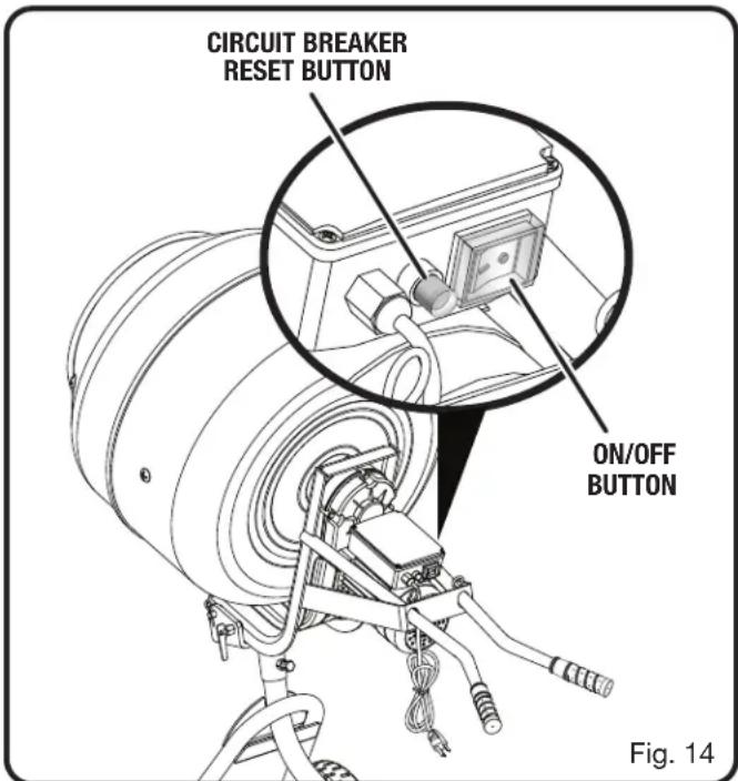
ON/OFF SWITCH - There is an easy access switch located on the rear of the motor assembly for turning the tool on and off.
RUGGED WHEELS - The durable plastic wheels allow you to move the product across smooth and rough surfaces.
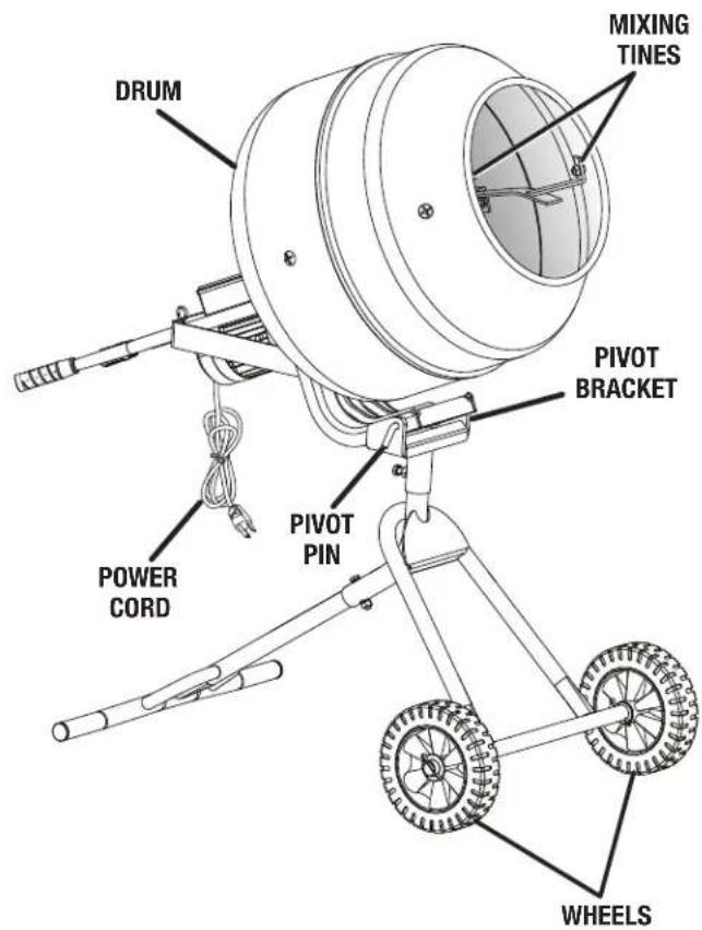
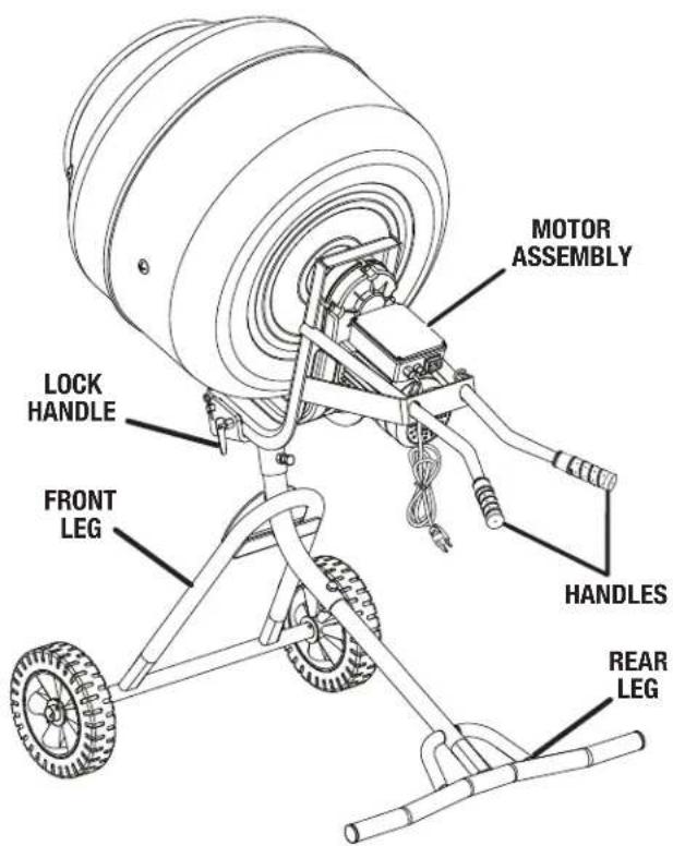
Fig. 3
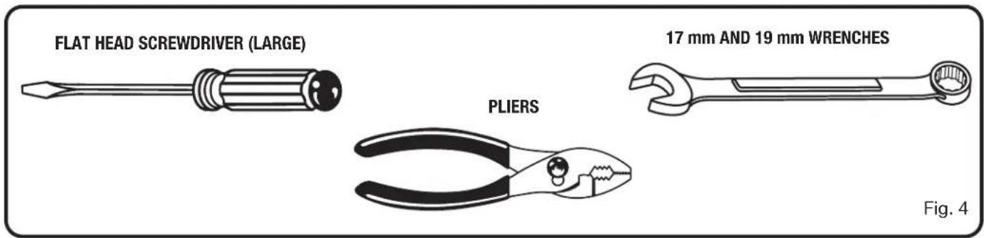
TOOLS NEEDED
The following tools (not included or drawn to scale) are needed for assembly:
LOOSE PARTS
Some of the Loose Parts shown below are stored in the drum. Parts not drawn to scale:
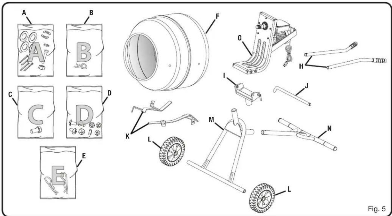
A - Plastic Bag (A)
Washer (Large) 4
Cotter Pin....4
Bolt (10 mm)....1
Arc Washer....2
Lock Washer ....1
Nut (10 mm)....1
B - Plastic Bag (B)
Hitch Pin (Small)....1
C - Plastic Bag (C)
Bolt (17 mm)....1
D - Plastic Bag (D)
Nut (12 mm)....4
Bolt (Phillips Hd.)....4
E - Plastic Bag (E)
Hitch Pin (Large)....2
F - Drum....1
G - Motor Assembly ....1
H - Handle 2
I - Pivot Bracket....1
J - Pivot Pin ....1
K - Mixing Tine 2
L - Wheel....2
M- Front leg ....1
N - Rear Leg....1
ASSEMBLY
UNPACKING
This product requires assembly.
- Carefully lift mixer from the carton and place it on a level work surface.
NOTE: This tool is heavy. To avoid back injury, keep your knees bent and lift with your legs, not your back, and get help when needed.

WARNING:
Do not use this product if any parts on the Loose Parts List are already assembled to your product when you unpack it. Parts on this list are not assembled to the product by the manufacturer and require customer installation. Use of a product that may have been improperly assembled could result in serious personal injury.
■ Inspect the tool carefully to make sure no breakage or damage occurred during shipping.
■ Do not discard the packing material until you have carefully inspected the tool, identified all loose parts, and satisfactorily operated the tool.
■ If any parts are damaged or missing, please call 1-800-525-2579 for assistance.

WARNING:
If any parts are damaged or missing, do not operate this tool until the parts are replaced. Use of this with damaged or missing parts could result in serious personal injury.

WARNING:
Do not attempt to modify this tool or create accessories not recommended for use with this tool. Any such alteration or modification is misuse and could result in a hazardous condition leading to possible serious personal injury.

WARNING:
Do not connect to power supply until assembly is complete. Failure to comply could result in accidental starting and possible serious personal injury.

WARNING:
Do not lift the mixer without help. Hold it close to your body. Keep your knees bent and lift with your legs, not your back. Ignoring these precautions can result in back injury.
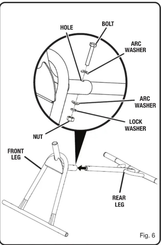
ASSEMBLING THE FRAME
See Figures 6-7.
■ Locate the following parts: Front Leg .... 1 Rear Leg .... 1
Pivot Bracket .... 1 Bolt (17 mm) in plastic bag (C) .... 1
Bolt (10 mm) in plastic bag (A)....1 Nut (10 mm) in plastic bag (A)....1
Arc Washers in plastic bag (A)....2
Lock Washer in plastic bag (A)....1
■ Slide the rear leg into the front leg as shown.
■ Align the holes in the legs.
■ Insert 10 mm bolt through arc washer and holes in the legs.
■ Install arc washer, lock washer, and nut onto bolt. Tighten securely.
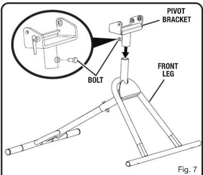
ASSEMBLY
■ Slide the pivot bracket onto the top of the front leg.
■ Install 17 mm bolt through the hole in the pivot bracket and tighten to prevent it from rotating.
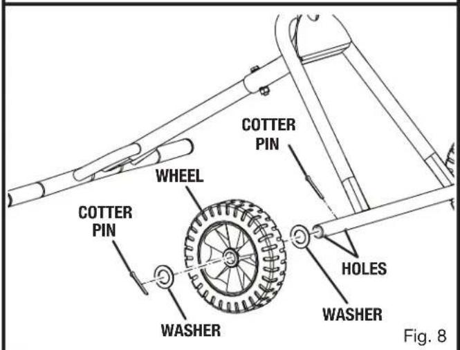
INSTALLING THE WHEELS
See Figure 8.
- Locate the following parts: Wheel 2
Cotter Pin in plastic bag (A) 4
Washer (Large) in plastic bag (A)....4
■ Raise the front leg and position props beneath it for support.
- Locate the two holes on the left end of the front leg.
■ Install a cotter pin into the hole closest to the center of the front leg.
■ Slide a washer, a wheel, and a second washer onto the front leg until it contacts the cotter pin.
■ Install a cotter pin into the second hole.
■ Using pliers, bend the ends of the cotter pins to secure the wheel in place.
■ Repeat the process on the other side to install second wheel.
INSTALLING THE MOTOR ASSEMBLY
See Figures 9 - 10.

WARNING:
Be careful to avoid pinching your fingers or hands when installing the motor assembly onto the pivot bracket.
- Locate the following parts:
Motor Assembly....1
Hitch Pin (Small) in plastic bag (B)....1
Pivot Pin ....1
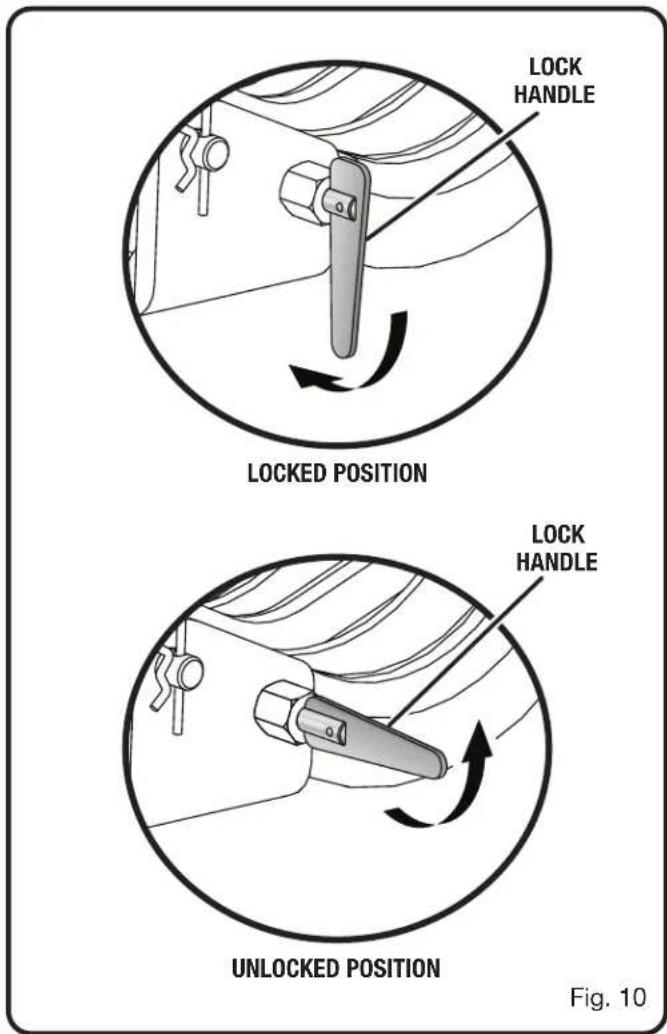
■ Pull the lock handle away from the pivot bracket and place it in the unlocked position.
■ With the help of a second person, hold the motor assembly above the pivot bracket.
NOTE: One side of the motor assembly has two holes and the other has one. The side with two holes should be on the same side as the lock handle as shown in figure 9.
■ Align the holes on the motor assembly with the hole and lock handle on the pivot bracket.
■ Lower the motor assembly into place.
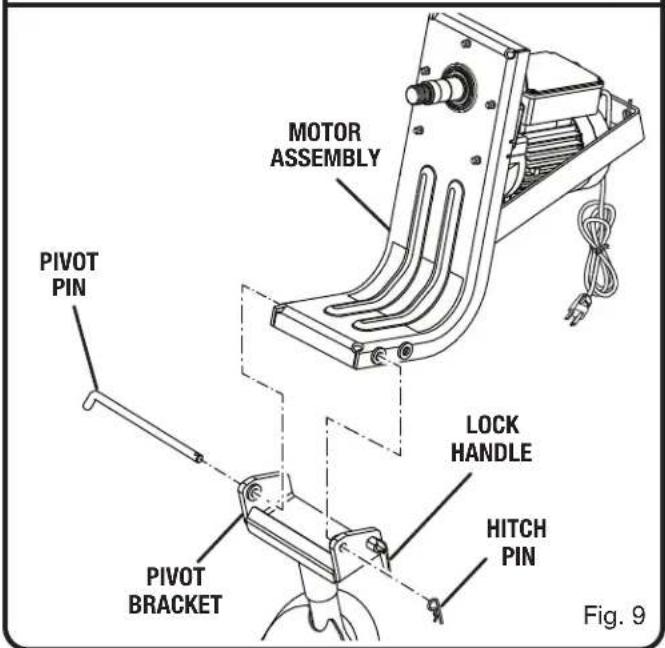
ASSEMBLY
■ Pull the lock handle away from the pivot bracket and place it in the locked position.
■ Slowly release the lock handle and allow it to enter the hole in the motor assembly that is closest to the motor.
■ Insert the pivot pin through the holes in the pivot bracket and the motor assembly and secure it with the hitch pin.
ATTACHING THE HANDLES
See Figure 11.
- Locate the following parts:
Handle ....2
Hitch Pin (Large) in plastic bag (E).....2
■ Slide a handle through one of the openings at the rear of the motor assembly and onto the bracket at the front of the assembly.
NOTE: Position the handle so the notches in the handle slide onto the notches on the bracket.
■ Install a hitch pin into the hole in the handle to secure it in place. Press down firmly on the hitch pin and make certain it is secure.
■ Repeat the process to secure the second handle.

ASSEMBLY
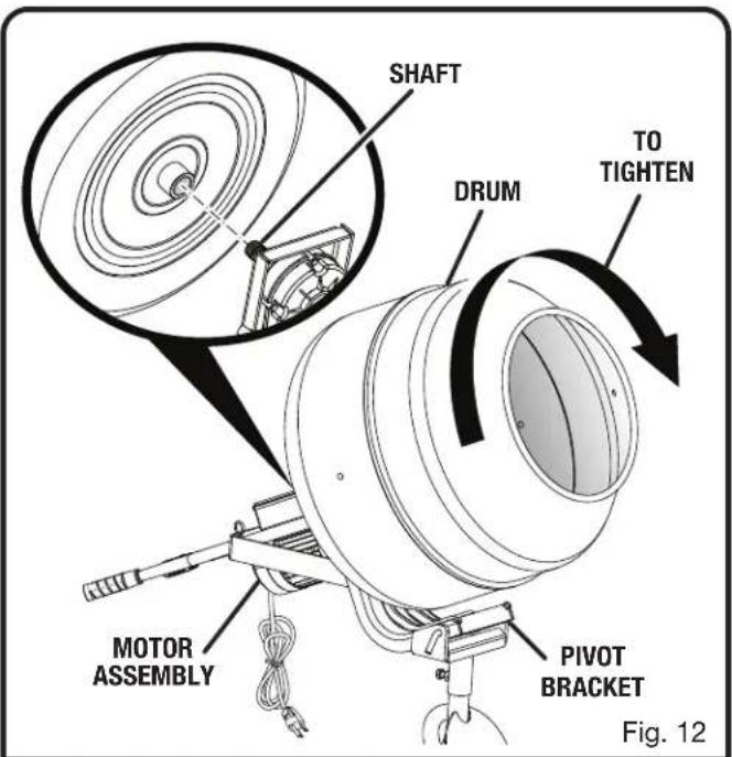
SECURING THE DRUM
See Figure 12.

CAUTION:
Double check all setups. Make sure that the legs, pivot bracket, wheels, motor assembly, and handles are installed correctly prior to installing the drum.
■ Locate the drum.
■ Tighten the bolt at the rear of the pivot bracket to prevent the drum from rotating.
■ With the help of a second person, place the drum onto the motor shaft.
NOTE: The drum is heavy. To avoid back injury, lift with your legs, not your back, and get help when needed.
■ Screw the drum onto the motor shaft by turning it clockwise. Tighten securely.
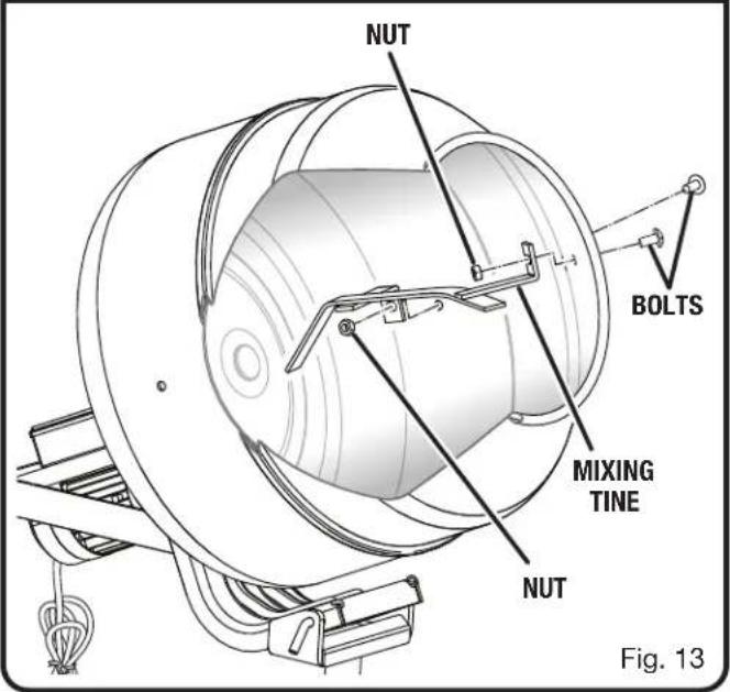
INSTALLING THE MIXING TINES
See Figure 13.
- Locate the following parts: Mixing Tine .... 2
Nut (12 mm) in plastic bag (D) 4
Bolt (Phillips Hd.) in plastic bag (D).... 4
■ Place the mixing tines into the drum with the angled ends pointing toward the inside of the drum.
■ Align the holes in the tines with the holes in the drum.
■ Install nuts and bolts as shown. Tighten securely.
OPERATION

DANGER:
Risk of explosion. Do not use this tool to mix flammable or explosive materials. Fire or explosion can cause severe burns or death.

WARNING:
Do not allow familiarity with products to make you careless. Remember that a careless fraction of a second is sufficient to inflict severe injury.

WARNING:
Always wear eye protection with side shields marked to comply with ANSI Z87.1 when operating this equipment. Failure to do so could result in objects being thrown into your eyes, resulting in possible serious injury.

WARNING:
Do not use any attachments or accessories not recommended by the manufacturer of this product. The use of attachments or accessories not recommended can result in serious personal injury.

WARNING:
Use safety equipment. Protect your eyes, skin, and lungs while filling, mixing, and emptying the mixer. Failure to do so may cause serious personal injury.

WARNING:
Do not reach into the drum with your hands or insert any other objects including trowels and shovels into it while mixing. Contact with the tines or substances inside the drum may lead to serious personal injury.
NOTICE:
Before each use, inspect the entire product for damaged, missing, or loose parts such as screws, nuts, bolts, caps, etc. Tighten securely all fasteners and caps and do not operate this product until all missing or damaged parts are replaced. Please contact customer service or a qualified service center for assistance.
APPLICATIONS
You may use this tool for the purposes listed below:
■ Mixing stucco, cement, mortar, aggregates (i.e. sand, gravel, etc.), and other materials.
The on/off switch on the back of the motor assembly is used to turn the mixer on and off. When the mixer is turned on, the drum will spin. When the mixer is turned off, the drum will stop.
OVERLOAD PROTECTION
See Figure 14.
When the mixer is overloaded or the motor is overheated for any reason, the circuit breaker will trip and the mixer will automatically shut off. Before resuming operation, allow the motor to cool. After the motor is cool, press the circuit breaker reset button and turn the motor on to continue mixing. If the mixer still does not resume operation, unplug the tool and empty some or all of the batch load. Do not force the mixer.
NOTICE:
Routinely make a visual inspection of the mixer and the material being mixed. Do not let materials dry and harden inside the drum or on any part of the product. Failure to follow this warning could result in property damage or malfunction of the product.
NOTICE:
Use caution when working with fast hardening material such as quick set concrete. A few minutes of inactivity may be sufficient to allow the material to set. Setting times vary; refer to the material manufacturer's instructions.
OPERATION
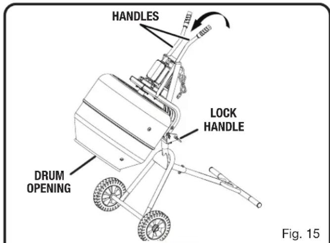
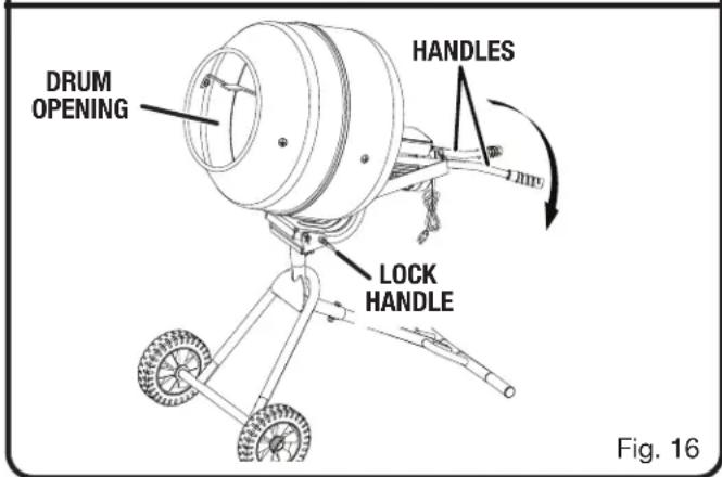
RAISING AND LOWERING THE DRUM OPENING
See Figures 15 - 16.

WARNING:
When changing the drum angle, keep hands and cords away from pinch points. Failure to heed this warning could result in fingers being pinched or cords being damaged.
To lower the drum opening:
■ Pull the lock handle away from the pivot bracket and place it in the unlocked position.
■ Lift the handles up to lower the drum opening.
NOTE: The drum opening should be in this position when emptying and cleaning the mixer.
To raise the drum opening:
■ Press down on the handles to raise the drum opening.
NOTE: The drum opening should be in this position when adding and mixing materials.
■ To lock the drum in this position, pull the lock handle away from the pivot bracket, place it in the locked position, and allow it to enter the hole in the motor assembly.
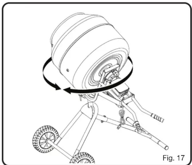
ROTATING THE DRUM
See Figure 17.
To rotate the drum:
■ Turn the mixer off.
■ Loosen the bolt on the back of the pivot bracket.
■ Firmly grasp the handles and move the drum to the left or right.
NOTE: The drum can be rotated 360 degrees around the frame (front and rear leg).
■ Tighten the bolt at the rear of the pivot bracket to prevent the drum from rotating.
MOVING THE MIXER

WARNING:
To reduce the risk of accidental starting, property damage, and/or serious personal injury always unplug the mixer and empty the drum prior to moving the mixer.
■ Empty the drum.
■ Unplug the mixer.
NOTE: Wrap the cord to prevent it from dangling and becoming a tripping hazard.
■ Press down on the handles to raise the drum opening.
■ Lock the drum in place.
■ Tighten the bolt at the rear of the pivot bracket to prevent the drum from rotating.
■ Tilt the machine away from you until it balances on the wheels, then roll the machine to the desired location. Do not tilt forward or sideways when moving.
NOTICE:
Do not overtilt! Use caution when moving the mixer across thresholds and uneven terrain.
natural_image
Technical line drawing of a mechanical device with rotating components and wheels (no text or symbols)OPERATION
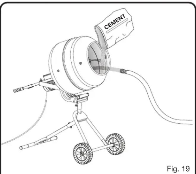
ADDING/MIXING MATERIALS
See Figures 18 - 19.

WARNING:
To reduce the risk of a tipping hazard, operate the mixer on a flat, stable surface. Operating the mixer on slopes or uneven surfaces increases the risk of tipping accidents that can result in severe injury. For your safety, always ensure the mixer is stable before and after turning on the motor and never operate the mixer on a surface with an incline greater than 5^ .

WARNING:
Keep hands away from the drum while it is spinning. Hands and other body parts can be drawn into the drum while it is spinning, resulting in serious personal injury.

WARNING:
Never leave the concrete mixer running unattended. Unplug mixer and empty the drum when leaving work area or when mixer is out of your line of sight.

WARNING:
Mix and prepare materials according to the material manufacturer's instructions.
NOTICE:
Routinely make a visual inspection of the mixer and the material being mixed. Do not let materials dry and harden inside the drum or on any part of the product. Failure to follow this warning could result in property damage or malfunction of the product.
NOTICE:
Use caution when working with fast hardening material such as quick set concrete. A few minutes of inactivity may be sufficient to allow the material to set. Setting times vary, refer to the material manufacturer's instructions.
NOTICE:
Do not exceed the batch capacity of this tool. Overfilling the drum could damage the motor.
■ Move the mixer to the work area and ensure it is on a flat, level surface.
NOTE: To increase stability and reduce the risk of a tipping hazard, do not operate the mixer on slopes or uneven surfaces.
■ Press down on the handles to raise the drum opening.
■ Lock the drum in place.
- Plug the mixer into a power source.
■ Turn the mixer on and let the drum spin.
NOTE: To protect the motor and ensure that materials mix evenly, turn the motor on prior to filling the mixer.
NOTICE:
Always keep the drum's opening in view when filling or emptying the concrete mixer. Certain mixing substances can harden quickly and could cause property damage or personal injury if spilled.
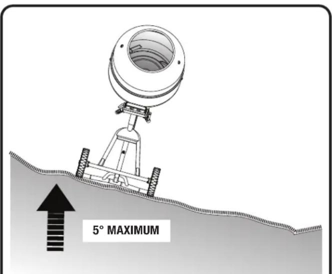
Fig. 18
OPERATION
- Carefully pour dry and wet mixing material into the drum. Refer to material manufacturer's instructions for details. Mixing times may vary.
NOTE: The mixer has a batch capacity of 270 lbs. (2.5 cu. ft). Do not overload the tool.
■ When mixing is complete empty the drum, turn off the motor, and clean the mixer as described later.
EMPTYING THE DRUM
See Figure 20.

WARNING:
Keep hands away from the drum while it is spinning. Hands and other body parts can be drawn into the drum while it is spinning, resulting in serious personal injury.
NOTICE:
Use caution when working with fast hardening material such as quick set concrete. A few minutes of inactivity may be sufficient to allow the material to set. Setting times vary, refer to the material manufacturer's instructions.
NOTICE:
Routinely make a visual inspection of the mixer and the material being mixed. Do not let materials dry and harden inside the drum or on any part of the product. Failure to follow this warning could result in property damage or malfunction of the product.
■ Add and mix materials as described in the previous section.
■ Turn the mixer off.
■ Loosen the bolt on the back of the pivot bracket.
■ Carefully rotate the drum until it is pointing away from the frame (front and rear leg) and towards the work area.
■ Tighten the bolt at the rear of the pivot bracket to prevent the drum from rotating.
NOTICE:
Always keep the drum's opening in view when filling or emptying the concrete mixer. Certain mixing substances can harden quickly and could cause property damage or personal injury if spilled.
■ Unlock the drum.
■ Slowly lift the handles up to lower the drum opening.
■ Once the drum is empty or the job is complete, raise the drum opening and lock the drum in place.
■ Clean the mixer as described later.
natural_image
Technical line drawing of a cement-based mechanical device with wheels and a labeled component (no text or symbols beyond label)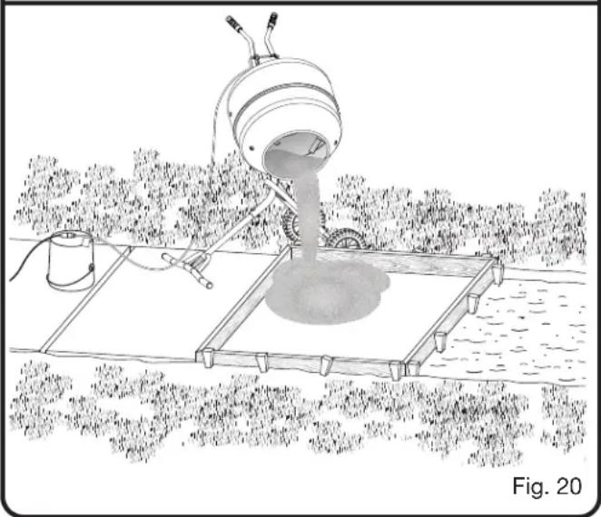
natural_image
Illustration of a bucket pouring liquid into a container on a floating platform, surrounded by trees (no text or symbols)OPERATION
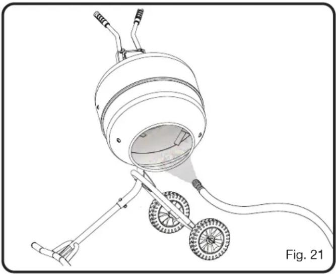
CLEANING THE DRUM
See Figure 21.
■ Unplug the mixer.
■ Empty the drum.
■ Unlock the drum.
■ Lift the handles up to lower the drum opening.
■ Using a garden hose, spray clean water into the drum and rinse away any remaining material

WARNING:
To reduce the risk of electric shock, do not direct water at or allow water to enter the motor assembly.
■ Dispose of concrete, rinse water, and other substances in areas designated for that purpose. Local, state or federal laws may prohibit disposal of these materials in storm drains, roadsides, landfills, or other locations. Consult your local waste authority for information regarding available disposal options.
■ Clean the exterior of the unit using a cloth and warm water.
NOTE: If necessary, clean the motor assembly with a dry cloth. Do not allow water to enter the motor assembly.
■ Dry the unit completely and store for later use.
natural_image
Line drawing of a mechanical device with wheels and a spray gun, labeled Fig. 21 (no text or symbols on the diagram itself)MAINTENANCE

WARNING:
When servicing, use only authorized replacement parts. Use of any other parts can create a hazard or cause product damage.
NOTICE:
Periodically, inspect the entire product for damaged, missing, or loose parts such as screws, nuts, bolts, caps, etc. Tighten securely all fasteners and caps and do not operate this product until all missing or damaged parts are replaced. Please contact customer service or a qualified service center for assistance.
GENERAL MAINTENANCE
Avoid using solvents when cleaning plastic parts. Most plastics are susceptible to damage from various types of commercial solvents and may be damaged by their use. Use clean cloths to remove dirt, dust, oil, grease, etc.

WARNING:
Do not at any time let brake fluids, gasoline, petroleum-based products, penetrating oils, etc., come in contact with plastic parts. Chemicals can damage, weaken, or destroy plastic which can result in serious personal injury.
LUBRICATION
All of the bearings in this product are lubricated with a sufficient amount of high grade lubricant for the life of the unit under normal operating conditions. Therefore, no further bearing lubrication is required.
TROUBLESHOOTING
PROBLEM POSSIBLE CAUSE SOLUTION
| Mixer won’t start. Power supply not connected. On/off switch is in the off position. Motor overloaded and circuit breaker is tripped. | Connect to power supply. Put on/off switch in on position. Allow motor to cool, press the circuit breaker reset button and put on/off switch in on position. NOTE: If the mixer still does not start, unplug the tool and empty some or all of the batch load. Do not force the mixer. |
| Mixer stops during operation. Power supply is disconnected. Motor overloaded and circuit breaker is tripped. | Reconnect power supply. Allow motor to cool, press the circuit breaker reset button and put on/off switch in on position. NOTE: If the mixer still does not start, unplug the tool and empty some or all of the batch load. Do not force the mixer. |
| Excessive noise or vibration while drum is spinning. | Pivot pin and/or lock handle is not secure Stop the motor and fully insert the pivot pin and/or lock handle to lock the drum in place. |
| Drum lowers unexpectedly during operation, | Pivot pin and/or lock handle is not secure. Stop the motor and fully insert the pivot pin and/or lock handle to lock the drum in place. |
AVERTISSEMENTS DE SÉCURITÉ RELATIVES AUX OUTILS ÉLECTRIQUES

AVERTISSEMENT:
FIXATION DES POIGNÉES
Voir la figure 11.
natural_image
Technical line drawing of a mechanical device with wheels and a rotating wheel (no text or symbols)UTILISATION
Fig. 18
UTILISATION
natural_image
Line drawing of a CIMENT instrument with wheels and a handle, labeled Fig. 19 (no text or symbols on the device itself)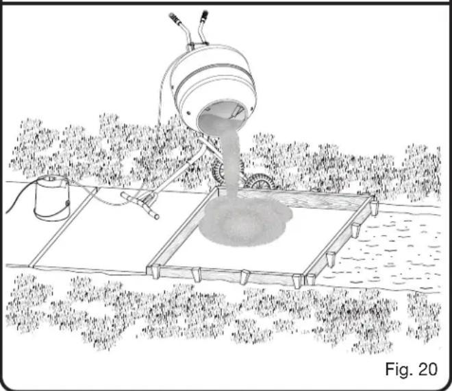
natural_image
Illustration of a mechanical device pouring liquid into a floating platform over water, with no visible text or symbols.UTILISATION
NETTOYAGE DU TAMBOUR
Voir la figure 21.
natural_image
Line drawing of a mechanical device with wheels and spray gun, labeled as Fig. 21 (no text or symbols on the diagram itself)ENTRETIEN

AVERTISSEMENT :
PROBLÈME CAUSE POSSIBLE SOLUTION
0-2,0 2,1-3,4 3,5-5,0 5,1-7,0 7,1-12,0 12,1-16,0
| Longitud del cordón (A.W.G.) | Calibre conductores | |||||
| 25' | 16 | 16 | 16 | 16 | 14 | 14 |
| 50' | 16 | 16 | 16 | 14 | 14 | 12 |
| 100' | 16 | 16 | 14 | 12 | 10 | — |
natural_image
Technical line drawing of a mechanical device with rotating components and wheels (no text or symbols)FUNCIONAMIENTO
AVISO:
Fig. 18
FUNCIONAMIENTO
natural_image
Technical line drawing of a cementing machine with wheels and a labeled component (no text or symbols beyond label)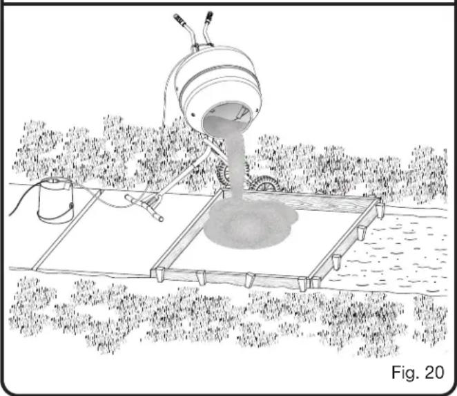
natural_image
Illustration of a water spray machine spraying water onto a floating platform in a field (no text or symbols)FUNCIONAMIENTO
CÓMO LIMPIAR EL TAMBOR
Vea la figura 21.
natural_image
Technical line drawing of a mechanical device with wheels and spray gun, labeled Fig. 21 (no text or symbols on the diagram itself)MANTENIMIENTO

ADVERTENCIA:
To request service, purchase replacement parts,
locate an Authorized Service Center or obtain Customer or Technical Support:
Visit www.ryobitools.com or call 1-800-525-2579
If any parts or accessories are damaged or missing, do not return this product to the store.
Call 1-800-525-2579 for immediate service.
Please obtain your model and serial number from the product data plate.
This product is covered under a 3-year limited Warranty. Proof of purchase is required.
MODEL NUMBER* ____ SERIAL NUMBER ____
*Model number on product may have additional letters at the end. These letters designate manufacturing information and should be provided when calling for service.
RYOBI is a registered trademark of Ryobi Limited and is used pursuant to a license granted by Ryobi Limited.