P611 - Plane RYOBI - Free user manual and instructions
Find the device manual for free P611 RYOBI in PDF.

| Product Type | Cordless Electric Planer |
| Brand | RYOBI |
| Model | P611 |
| Power | Lithium-ion battery (18 V One+) |
| No-load Speed | 11,000 rpm |
| Max Planing Width | 83 mm (3-1/4 in) |
| Max Planing Depth | 1.6 mm (1/16 in) |
| Max Rabbeting Depth | 12.7 mm (1/2 in) |
| Main Functions | Planing, chamfering, rabbet cutting |
| Dust Extraction Connection | 32 mm (1-1/4 in) port for vacuum |
| Dust Bag | Included, directional discharge (right/left) |
| Safety Stand | Automatic pivoting, protects blades at rest |
| Blade Maintenance | Reversible blades (2 sides); replace as a pair (ref. 039821001057) |
| Replacement Belt | Ref. 039821001042 |
| Safety | Eye protection required; remove battery before adjustments |
| Dimensions (approx.) | 300 x 150 x 150 mm |
| Weight (approx.) | 2.5 kg (without battery) |
Frequently Asked Questions - P611 RYOBI
User questions about P611 RYOBI
0 question about this device. Answer the ones you know or ask your own.
Ask a new question about this device
Download the instructions for your Plane in PDF format for free! Find your manual P611 - RYOBI and take your electronic device back in hand. On this page are published all the documents necessary for the use of your device. P611 by RYOBI.
USER MANUAL P611 RYOBI
INCLUDES: Planer, Dust Bag, Edge Guide, Blade Wrench, Tool Bag, Operator's Manual
TABLE OF CONTENTS
****************************************************************************************
■ General Power Tool Safety
Warnings....2-3
■ Planer Safety Warnings....3
■ Symbols......4
■ Features....5
■ Assembly....5
■ Operation....5-7
■ Maintenance......8-9
■ Accessories....9
■ Illustrations ....11-13
■ Parts Ordering / Service ..... Back Page

WARNING: To reduce the
risk of injury, the user must read and understand the operator's manual before using this product.
SAVE THIS MANUAL FOR
FUTURE REFERENCE
Read all safety warnings and all instructions. Failure to follow the warnings and instructions may result in electric shock, fire and/or serious injury.
Save all warnings and instructions for future reference. The term “power tool” in the warnings refers to your mains-operated (corded) power tool or battery-operated (cordless) power tool.
WORK AREA SAFETY
- Keep work area clean and well lit. Cluttered or dark areas invite accidents.
■ Do not operate power tools in explosive atmospheres, such as in the presence of flammable liquids, gases or dust. Power tools create sparks which may ignite the dust or fumes. - Keep children and bystanders away while operating a power tool. Distractions can cause you to lose control.
ELECTRICAL SAFETY
■ Power tool plugs must match the outlet. Never modify the plug in any way. Do not use any adapter plugs with earthed (grounded) power tools. Unmodified plugs and matching outlets will reduce risk of electric shock.
■ Avoid body contact with earthed or grounded surfaces such as pipes, radiators, ranges and refrigerators. There is an increased risk of electric shock if your body is earthed or grounded.
■ Do not expose power tools to rain or wet conditions. Water entering a power tool will increase the risk of electric shock.
- Do not abuse the cord. Never use the cord for carrying, pulling or unplugging the power tool. Keep cord away from heat, oil, sharp edges or moving parts. Damaged or entangled cords increase the risk of electric shock.
■ When operating a power tool outdoors, use an extension cord suitable for outdoor use. Use of a cord suitable for outdoor use reduces the risk of electric shock.
If operating a power tool in a damp location is unavoidable, use a ground fault circuit interrupter (GFCI) protected supply. Use of a GFCI reduces the risk of electric shock.
Use this product only with batteries and chargers listed in tool/appliance/battery pack/charger correlation supplement 987000-432.
PERSONAL SAFETY
■ Stay alert, watch what you are doing and use common sense when operating a power tool. Do not use a power tool while you are tired or under the influence of drugs, alcohol or medication. A moment of inattention while operating power tools may result in serious personal injury.
■ Use personal protective equipment. Always wear eye protection. Protective equipment such as dust mask, non-skid safety shoes, hard hat, or hearing protection used for appropriate conditions will reduce personal injuries.
■ Prevent unintentional starting. Ensure the switch is in the off-position before connecting to power source and/or battery pack, picking up or carrying the tool. Carrying power tools with your finger on the switch or energising power tools that have the switch on invites accidents.
■ Remove any adjusting key or wrench before turning the power tool on. A wrench or a key left attached to a rotating part of the power tool may result in personal injury.
- Do not overreach. Keep proper footing and balance at all times. This enables better control of the power tool in unexpected situations.
■ Dress properly. Do not wear loose clothing or jewellery. Keep your hair, clothing and gloves away from moving parts. Loose clothes, jewellery or long hair can be caught in moving parts.
If devices are provided for the connection of dust extraction and collection facilities, ensure these are connected and properly used. Use of dust collection can reduce dust-related hazards.
■ Do not wear loose clothing or jewelry. Contain long hair. Loose clothes, jewelry, or long hair can be drawn into air vents.
- Do not use on a ladder or unstable support. Stable footing on a solid surface enables better control of the power tool in unexpected situations.
POWER TOOL USE AND CARE
- Do not force the power tool. Use the correct power tool for your application. The correct power tool will do the job better and safer at the rate for which it was designed.
- Do not use the power tool if the switch does not turn it on and off. Any power tool that cannot be controlled with the switch is dangerous and must be repaired.
■ Disconnect the plug from the power source and/or the battery pack from the power tool before making any adjustments, changing accessories, or storing power tools. Such preventive safety measures reduce the risk of starting the power tool accidentally.
■ Store idle power tools out of the reach of children and do not allow persons unfamiliar with the power tool or these instructions to operate the power tool. Power tools are dangerous in the hands of untrained users. - Maintain power tools. Check for misalignment or binding of moving parts, breakage of parts and any other condition that may affect the power tool's operation. If damaged, have the power tool repaired before use. Many accidents are caused by poorly maintained power tools.
GENERAL POWER TOOL SAFETY WARNINGS
- Keep cutting tools sharp and clean. Properly maintained cutting tools with sharp cutting edges are less likely to bind and are easier to control.
■ Use the power tool, accessories and tool bits etc. in accordance with these instructions, taking into account the working conditions and the work to be performed. Use of the power tool for operations different from those intended could result in a hazardous situation.
BATTERY TOOL USE AND CARE
■ Recharge only with the charger specified by the manufacturer. A charger that is suitable for one type of battery pack may create a risk of fire when used with another battery pack.
■ Use power tools only with specifically designated battery packs. Use of any other battery packs may create a risk of injury and fire.
■ When battery pack is not in use, keep it away from other metal objects, like paper clips, coins, keys, nails,
screws or other small metal objects, that can make a connection from one terminal to another. Shorting the battery terminals together may cause burns or a fire.
■ Under abusive conditions, liquid may be ejected from the battery; avoid contact. If contact accidentally occurs, flush with water. If liquid contacts eyes, additionally seek medical help. Liquid ejected from the battery may cause irritation or burns.
SERVICE
■ Have your power tool serviced by a qualified repair person using only identical replacement parts. This will ensure that the safety of the power tool is maintained.
■ When servicing a power tool, use only identical replacement parts. Follow instructions in the Maintenance section of this manual. Use of unauthorized parts or failure to follow Maintenance instructions may create a risk of shock or injury.
PLANER SAFETY WARNINGS
■ Wait for the cutter to stop before setting the tool down. An exposed rotating cutter may engage the surface leading to possible loss of control and serious injury.
■ Use clamps or another practical way to secure and support the workpiece to a stable platform. Holding the work by hand or against the body leaves it unstable and may lead to loss of control.
■ Hold the power tool by insulated gripping surfaces only.
- Know your power tool. Read operator's manual carefully. Learn its applications and limitations, as well as the specific potential hazards related to this power tool. Following this rule will reduce the risk of electric shock, fire, or serious injury.
■ Always wear eye protection with side shields marked to comply with ANSI Z87.1. Following this rule will reduce the risk of serious personal injury.
■ Protect your lungs. Wear a face or dust mask if the operation is dusty. Following this rule will reduce the risk of serious personal injury.
■ Protect your hearing. Wear hearing protection during extended periods of operation. Following this rule will reduce the risk of serious personal injury.
■ Battery tools do not have to be plugged into an electrical outlet; therefore, they are always in operating condition. Be aware of possible hazards when not using your battery tool or when changing accessories. Following this rule will reduce the risk of electric shock, fire, or serious personal injury.
- Do not place battery tools or their batteries near fire or heat. This will reduce the risk of explosion and possibly injury.
- Do not crush, drop or damage battery pack. Do not use a battery pack or charger that has been dropped or received a sharp blow. A damaged battery is subject to explosion. Properly dispose of a dropped or damaged battery immediately.
■ Batteries can explode in the presence of a source of ignition, such as a pilot light. To reduce the risk of serious personal injury, never use any cordless product in the presence of open flame. An exploded battery can propel debris and chemicals. If exposed, flush with water immediately. - Do not charge battery tool in a damp or wet location. Do not use, store, or charge battery packs or products in locations where the temperature is less than 50°F or more than 100°F. Do not store outside or in vehicles.
■ Under extreme usage or temperature conditions, battery leakage may occur. If liquid comes in contact with your skin, wash immediately with soap and water. If liquid gets into your eyes, flush them with clean water for at least 10 minutes, then seek immediate medical attention. Following this rule will reduce the risk of serious personal injury.
■ Save these instructions. Refer to them frequently and use them to instruct others who may use this tool. If you loan someone this tool, loan them these instructions also.
SYMBOLS
| The following signal words and meanings are intended to explain the levels of risk associated with this product. | ||
| SYMBOL | SIGNAL | MEANING |
 | DANGER: | Indicates a hazardous situation, which, if not avoided, will result in death or serious injury. |
 | WARNING: | Indicates a hazardous situation, which, if not avoided, could result in death or serious injury. |
 | CAUTION: | Indicates a hazardous situation, that, if not avoided, may result in minor or moderate injury. |
| NOTICE: | (Without Safety Alert Symbol) Indicates information considered important, but not related to a potential injury (e.g. messages relating to property damage). | |
| Some of the following symbols may be used on this product. Please study them and learn their meaning. Proper interpretation of these symbols will allow you to operate the product better and safer. SYMBOL NAME DESIGNATION/EXPLANATION | ||
 | Safety Alert Indicates a potential | personal injury hazard. |
 | Read Operator's Manual | To reduce the risk of injury, user must read and understand operator's manual before using this product. |
 | Eye Protection | Always wear eye protection with side shields marked to comply with ANSI Z87.1. |
 | Wet Conditions Alert Do not expose to rain or use in damp locations. | |
 | No Hands Symbol | Failure to keep your hands away from the blade will result in serious personal injury. |
 | Recycle Symbol | This product uses lithium-ion (Li-ion) batteries. Local, state or federal laws may prohibit disposal of batteries in ordinary trash. Consult your local waste authority for information regarding available recycling and/or disposal options. |
| V Volts Voltage | ||
| Hz Hertz Frequency (cycles per second) | ||
| min Minutes Time | ||
| == | Direct Current Type or a characteristic of current | |
| n0 | No Load Speed Rotational speed, at no load | |
| .../min Per Minute Revolutions, strokes, surface speed, orbits etc., per minute | ||
FEATURES
PRODUCT SPECIFICATIONS
No Load Speed 11,000/min.
Maximum Planing Width 3-1/4 in.
Maximum Planing Depth....1/16 in.
Maximum Rabbet Depth 1/2 in.
ASSEMBLY

WARNING:
Do not use this product if it is not completely assembled or if any parts appear to be missing or damaged. Use of a product that is not properly and completely assembled or with damaged or missing parts could result in serious personal injury.

WARNING:
Do not attempt to modify this product or create accessories or attachments not recommended for use with this product. Any such alteration or modification is misuse and could result in a hazardous condition leading to possible serious personal injury.
If any parts are damaged or missing, please call 1-800-525-2579 for assistance.
OPERATION

WARNING:
Do not allow familiarity with tools to make you careless. Remember that a careless fraction of a second is sufficient to inflict serious injury.
■ Planing the edge of a piece of lumber
■ Making rabbet cuts in wood
■ Chamfering sharp edges of lumber
ADJUSTING THE EXHAUST DIRECTION
See Figure 1, page 11.

WARNING:
Always remove battery pack from the tool when you are assembling parts, making adjustments, cleaning, or when not in use. Removing battery pack will prevent accidental starting that could cause serious personal injury.

WARNING:
Collected dust from planing surface coatings such as polyurethanes, linseed oil, etc., can self-ignite in the planer dust bag or elsewhere and cause fire. To reduce the risk of fire, always empty the dust bag frequently while planing. NEVER store or leave a planer without totally emptying its dust bag. Also follow the recommendations of the coatings manufacturers.

WARNING:
Always wear eye protection with side shields marked to comply with ANSI Z87.1. Failure to do so could result in objects being thrown into your eyes resulting in possible serious injury.
Change the direction of the exhaust to either the right or left to control the direction of debris when working in confined areas.

WARNING:
Do not use any attachments or accessories not recommended by the manufacturer of this product. The use of attachments or accessories not recommended can result in serious personal injury.
To adjust the exhaust direction and dust bag:
■ Remove the battery pack.
■ To adjust exhaust to the right: Move the exhaust direction lever so the arrow points right (the handle will point left). Install the dust bag on the right exhaust port.
■ To adjust exhaust to the left: Move the exhaust direction lever so the arrow points left (the handle will point right). Install the dust bag on the left exhaust port.
NOTE: Check that the dust bag is attached to the same port selected by the exhaust direction lever.
APPLICATIONS
You may use this tool for the purposes listed below:
■ Planing the edge of a wooden door or shelf
OPERATION
ATTACHING THE DUST BAG
See Figure 2, page 11.
■ Remove the battery pack.
■ Slide the collar of the dust bag onto the exhaust port.
NOTE: To remove the dust bag, pull it straight out of the exhaust port.
NOTICE:
The dust bag fills quickly. Empty it often to prevent damage to the product.
ATTACHING THE PLANER TO A VACUUM
See Figure 3, page 11.
The chip collection system of the planer has a 1-1/4 in. port for inserting a vacuum hose.
■ Remove the battery pack.
■ Remove the dust bag.
■ Attach a vacuum hose to the left or right chip exhaust.
■ Set exhaust direction lever to the selected exhaust port.
■ Connect the vacuum to a power supply.
■ Turn vacuum on before starting cut.

WARNING:
When the tool is not connected to vacuum, always re-install the dust bag back onto the tool. Failure to do so could cause dust or foreign objects to be thrown into your face or eyes, which could result in possible serious injury.
INSTALLING/REMOVING BATTERY PACK
See Figure 4, page 12.
■ Lock the switch trigger.
- Insert the battery pack into the product as shown.
■ Make sure the latches on each side of the battery pack snap into place and the battery pack is secured in the product before beginning operation.
■ Depress the latches to remove the battery pack.
For complete charging instructions, see the operator's manuals for your battery pack and charger.
STARTING/STOPPING THE PLANER
See Figure 5, page 12.
■ To start the planer: Push the lock-off button from either side, and then depress the switch trigger.
■ To stop the planer: Release the switch trigger.
KICKSTAND
See Figure 6, page 12.
The planer has been equipped with an automatic pivoting kickstand that will prevent the blades from contacting the workbench when not in use. As you begin the planing operation, the kickstand will automatically retract as it passes over the edge of the workpiece. When setting the planer down on the workbench, the kickstand will automatically pivot down to prevent the blade from making any contact.

WARNING:
Make sure the kickstand operates freely at all times and that the area surrounding the kickstand is clear of debris. Failure to do so could result in serious personal injury.
PLANING DEPTH
See Figure 7, page 12.
When you begin planing a rough piece of material, the planer will only remove the high spots at first. Successive passes will remove more and more material. By removing no more than 1/64 in. with each pass, you will achieve the smoothest finish, even from the roughest workpiece.
Always begin by making test cuts in scrap wood to make sure that the planer is removing the desired amount of wood.
To set the planing depth:
■ Remove the battery pack.
■ Turn the depth adjustment knob clockwise to set the desired depth of cut. The maximum depth of cut is 1/16 in.
NOTE: Use only detented depth settings. Attempting cuts with the depth of cut settings between the detented positions can result in uneven cuts.
NOTE: To protect the blades during storage, transporting, etc., turn the depth adjustment knob counterclockwise to P on the depth of cut scale to park the blade.

WARNING:
Always clamp the workpiece securely before making a cut. Work moving during a cut could result in loss of control of the planer and cause serious injury.
■ Clamp the work securely.
■ Be sure the material to be planed is free of nails, staples, or screws.
■ Support the work so that the operation is on your side.
NOTICE:
Planing too fast results in a poor finish and increases chip build-up in the chip exhaust. Chip build-up restricts air flow and can cause motor overheating.
OPERATION

WARNING:
Do not attempt to clear a blocked chip exhaust until the blades stop and you have disconnected the product from the power source. Failure to heed this warning can result in serious personal injury.
PLANING
See Figure 8, page 12.
■ Clamp the work securely.
■ Adjust the planing depth. Refer to Planing Depth earlier in this manual.
- Hold the depth adjustment knob with one hand and the handle with your other hand.

WARNING:
Always use two hands on the tool for any operation; this assures that you maintain control and avoid risk of serious personal injury. Always properly support and clamp the work so that both hands are free to control the planer. Never operate the tool overhead or inverted from the proper operating position; serious personal injury may result.
■ Place the front shoe on the edge of work to be planed.
NOTE: Make sure the blades are not touching the work.
■ Apply pressure to the depth adjustment knob so that the front shoe is completely flat on the work.
■ Start the planer and let the motor reach maximum speed.
- Hold the planer firmly and push it forward into the work, using a slow, steady motion.
■ Plane slowly and empty the dust bag often.
■ Apply downward pressure toward the rear handle as you reach the end of the planed cut. This helps keep the rear section of the planer base in contact with the work and prevents the front of the planer from gouging the cut.

WARNING:
Be careful to avoid hitting nails or staples during plan-ing operation; this action could nick, crack, or damage blades.
NOTE: We suggest that you always keep an extra set of blades on hand. As soon as the blades in the planer show signs of becoming dull, replace them. The blades are reversible and can be reversed until both sides become dull.
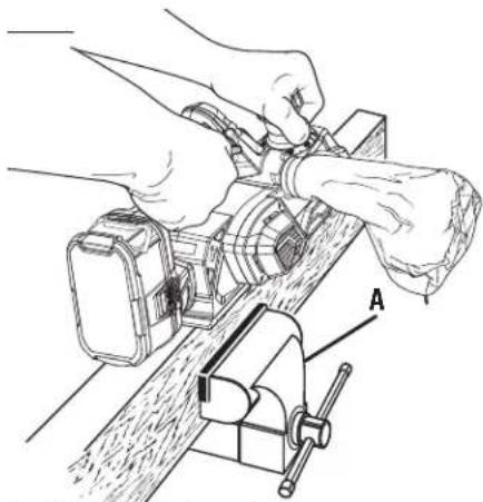
CHAMFERING
See Figure 9, page 12.
The planer is designed with a chamfering groove in the front shoe to chamfer corners of boards as shown. Before making a cut on good lumber, practice cutting on scrap lumber to determine the amount to be removed.
■ Clamp the work securely.
■ Hold the depth adjustment knob with one hand and the handle with your other hand.
■ Place the chamfering groove on the surface to be cut.
■ Start the planer and let the motor reach maximum speed.
- Hold the planer firmly and push it forward into the work, using a slow, steady motion.
■ Apply downward pressure to keep the planer flat at the beginning and the end of the work surface.
PLANING EDGES AND MAKING RABBET CUTS
The planer comes with an adjustable edge guide for precision edge planing and rabbit cutting. Attach the edge guide to either side of the planer for planing edges and attach the edge guide to the left side for making rabbit cuts.
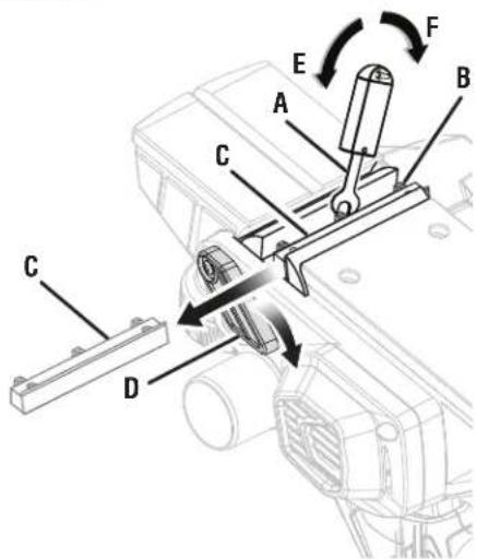
ATTACHING THE EDGE GUIDE FOR PLANING EDGES
See Figure 10, page 12.
■ Remove the battery pack.
■ Attach the bracket to the desired side of the planer and tighten the knob bolt securely.
■ Attach the edge guide to the bracket using the knob nut and the carriage head bolt.
■ Tighten the knob nut securely.
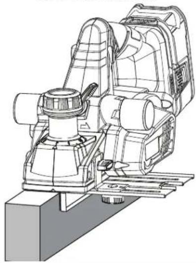
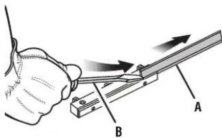
PLANING EDGES
See Figure 11, page 13.
Follow the directions in the Planing section earlier in this manual. Hold the edge guide firmly against the edge of the work surface.
ATTACHING THE EDGE GUIDE FOR MAKING RABBET CUTS
See Figure 10, page 12.
■ Remove the battery pack.
■ Attach the bracket to the left side of the planer and tighten the knob bolt securely.
■ Attach the edge guide loosely to the bracket using the knob nut and the carriage head bolt (do not tighten).
■ Adjust the edge guide to the desired width for the rabbet cut.
■ Tighten the knob nut securely.
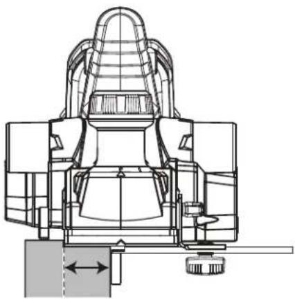
TO MAKE RABBET CUTS
See Figure 12, page 13.
Follow the directions in the Planing section earlier in this manual. Rest the edge guide firmly against the edge of the work surface.
The depth of the rabbit is determined by the depth of the cut and the number of passes made along the work surface. The maximum depth of the rabbit cut is 1/2 in. and has to be cut in 1/16 in. passes or less to reach the desired depth. The width of the rabbit cut is adjustable by moving the edge guide.
MAINTENANCE

WARNING:
When servicing, use only identical replacement parts. Use of any other parts may create a hazard or cause product damage.

WARNING:
Always wear eye protection with side shields marked to comply with ANSI Z87.1. Failure to do so could result in objects being thrown into your eyes resulting in possible serious injury.
GENERAL MAINTENANCE
Avoid using solvents when cleaning plastic parts. Most plastics are susceptible to damage from various types of commercial solvents and may be damaged by their use. Use clean cloths to remove dirt, dust, oil, grease, etc.

WARNING:
Do not at any time let brake fluids, gasoline, petroleum-based products, penetrating oils, etc., come in contact with plastic parts. Chemicals can damage, weaken or destroy plastic which may result in serious personal injury.
Electric tools used on fiberglass material, wallboard, spackling compounds, or plaster are subject to accelerated wear and possible premature failure because the fiberglass chips and grindings are highly abrasive to bearings, brushes, commutators, etc. Consequently, we do not recommend using this tool for extended work on these types of materials. However, if you do work with any of these materials, it is extremely important to clean the tool using compressed air.
LUBRICATION
All of the bearings in this tool are lubricated with a sufficient amount of high grade lubricant for the life of the unit under normal operating conditions. Therefore, no further lubrication is required.
CLEANING THE EXHAUST PORT AND EMPTYING THE DUST BAG
See Figure 13, page 13.
After using the planer for an extended period of time or when planing wet or green lumber, chips may build-up in the exhaust port and require cleaning. Chip build-up restricts air flow and causes the motor to overheat. Clean the exhaust port and empty the dust bag regularly.
■ Remove the battery pack.
■ Remove the dust bag from the exhaust port.
■ Clean the chip or dust build-up from the exhaust port of the planer with a small piece of wood. Do not use your hands or fingers.
■ Empty all debris from the dust bag and ensure that the collar is free of debris.
■ Replace the dust bag.
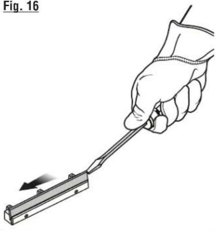
REPLACING BLADES
See Figures 14 - 16, page 13.
The planer blades are reversible. When one edge becomes dull, the blade can be reversed so that the other side can be used.
Always replace or reverse blades in pairs. Do not attempt to sharpen blades. If the blades in the planer show signs of becoming dull, chipped, or damaged in any way, replace them.
When replacing the blades, use recommended replacement blade only, RYOBI part number 039821001057.

WARNING:
Always wear heavy leather gloves and use caution when loosening blade screws and handling and/or changing blades. Blades are sharp and can cause serous personal injury.
■ Remove the battery pack.
- Secure the planer in an upside-down position.
■ Loosen the three screws securing the blade on the blade holder by turning counterclockwise with the provided blade wrench.
NOTE: Do not over-loosen the screws. If screws are too loose, alignment of the new blade will not be accurate.
NOTE: Before removing the old blades, take notice of the direction of cut as well as how the tapered edge of the old blades are oriented. The tapered edge of the new blades must be in the same orientation as the original blades, with the tapered edge on the same side as the screw heads and the flat edge facing the cutter block.
■ Depress the spring-loaded blade guard.
■ Push the blade holder out of the cutter block assembly using the tip of a screwdriver.
■ Remove the old blade from the blade holder by sliding the blade out using the tip of a screwdriver.
NOTE: If blade cannot be easily pushed out of blade holder after loosening blade securing screws, use a block of wood to break the blade loose from the blade holder with a short sharp blow. Then push the blade with a screwdriver to remove. If necessary, tap the block of wood sharply with a small hammer to break the blade loose.
■ Clean any sawdust or wood chips from around the blade area.
■ Slide the new blade into the slot of the blade holder.
■ Use a screwdriver to push the blade into the blade holder until it is centered into position.
■ Depress the spring-loaded blade guard.
MAINTENANCE
■ Insert the blade holder into the cutter block assembly.
■ Retighten the three blade securing screws using the blade wrench.
■ Repeat the above procedure to change the other blade.
REPLACING THE BELT
See Figures 17 - 18, page 13.
When replacing the belt, use the recommended replacement belt only, RYOBI part number 039821001042.
■ Remove the battery pack.
■ Remove belt cover screws.
■ Remove the belt cover.
■ Force the old belt from the small pulley by turning in the direction shown. As you turn the belt, pull and work it off the small pulley until it has been completely removed from both pulleys.
■ Install the new belt over the small pulley, being sure to align the grooves. As you turn the belt, push and work it onto the large pulley until it is in place.
■ Replace the belt cover.
■ Install belt cover screws and tighten securely.
NOTE: Do not overtighten the screws.
ACCESSORIES
Look for these accessories where you purchased this product or call 1-800-525-2579.
Planer Blades 039821001057
Belt 039821001042
NOTE: ILLUSTRATIONS START ON PAGE 11 AFTER FRENCH AND SPANISH LANGUAGE SECTIONS.
NOTES
AVERTISSEMENTS DE SÉCURITÉ GÉNÉRALES RELATIVES AUX OUTILS ÉLECTRIQUES

AVERTISSEMENT
REPLACEMENT DES LAMES
A - Lock-off button (bouton de verrouillage, botón del seguro de apagado)
B - Rear handle (poignée arrière, mango posterior)
C - Switch trigger (gâchette, gatillo delG interruptor)
D - Kickstand (béquille, soporte protector)
E - Exhaust ports (orifices d'échappement, escape de salidas de desechos)
F - Depth adjustment knob/front handle (bouton de réglage de profondeur / poignée avant, perilla de ajuste de profundidad / mango delantero)
G - Blade wrench (clé à lame, llave de las cuchillas)
H - Exhaust direction lever (réglage d'orientation d'évacuation, perilla de dirección del escape)
I - Edge guide/rabbet guide (guide de chant / guide de feuillure, guía para cepillado y rebajado de cantos)
J - Dust bag (sac à poussière, saco captapolvo)
K - Depth of cut scale (échelle de profondeur de coupe, escala de profundidad de corte)
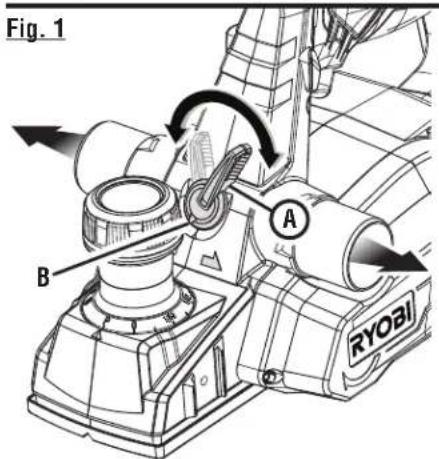
A - Exhaust direction lever (réglage d'orientation d'évacuation, perilla de dirección del escape)
B - Directional arrow (flèche de direction, flecha direccional)
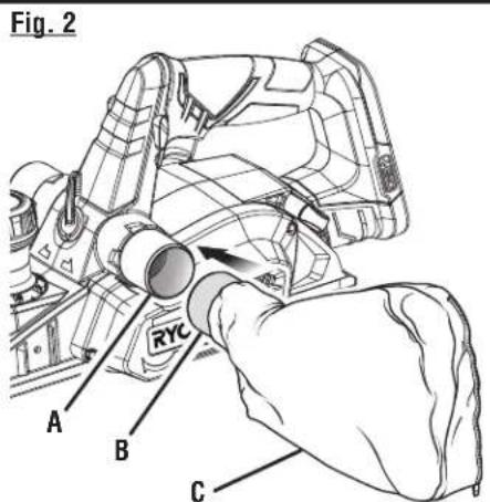
A - Exhaust port (orifice d'évacuation, escape de salida de desechos)
B - Collar (collier, collar)
C - Dust bag (sac à poussière, saco captapolvo)
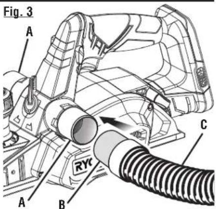
A - Exhaust ports (orifices d'évacuation, escape de salidas de desechos)
B - Collar (collier, collar)
C - Vac hose (tuyau d'aspirateur, manguera de la aspiradora)
Fig. 4
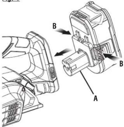
A - Battery pack (bloc-pile, paquete de batería)
B - Latch (loquet, pestillo)
Fig. 5
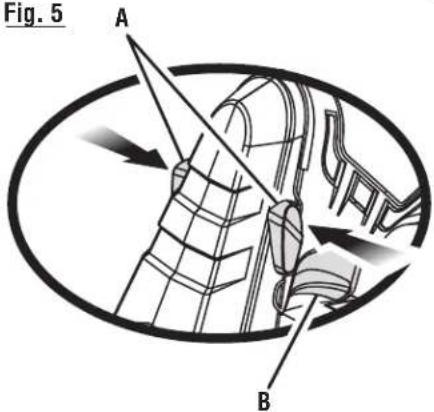
A - Lock-off button (bouton de verrouillage, botón del seguro de apagado)
B - Switch trigger (gâchette, gatillo del interruptor)
Fig. 6 Fig. 8
THE KICKSTAND PIVOTS DOWN WHEN
THE PLANER IS NOT IN USE
LA BÉQUILLE PIVOTE VERS LE BAS
LORSQUE LA RABOTEUSE N'EST PAS EN
FONCTIONNEMENT
EL SOPORTE PROTECTOR SE VOLTEA
HACIA ABAJO CUANDO NO ESTÁ
UTILIZÁNDOSE EL CEPILLO
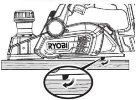
THE KICKSTAND RETRACTS WHEN
THE PLANER IS IN USE
LA BÉQUILLE SE RÉTRACTE
LORSQUE LA RABOTEUSE
EST EN FONCTIONNEMENT
EL SOPORTE PROTECTOR SE
RETRAE CUANDO ESTÁ
UTILIZÁNDOSE EL CEPILLO
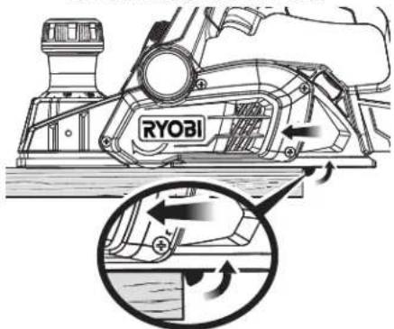
Fig. 7
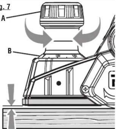
A - Depth adjustment knob (bouton de réglage de profondeur, perilla de ajuste de profundidad)
B - Depth of cut scale (échelle de réglage de la profundeur, escala de profundidad de corte)
natural_image
Illustration of hands operating a lathe machine with a vise, labeled 'A' (no text or symbols beyond label)A - Clamp (bride, abrazadera)
Fig. 9 CHAMFERING CORNERS
CHANFREINER LE BORD DES COINS
ACHAFLANAR LOS ESQUINAS
DE LAS TABLAS
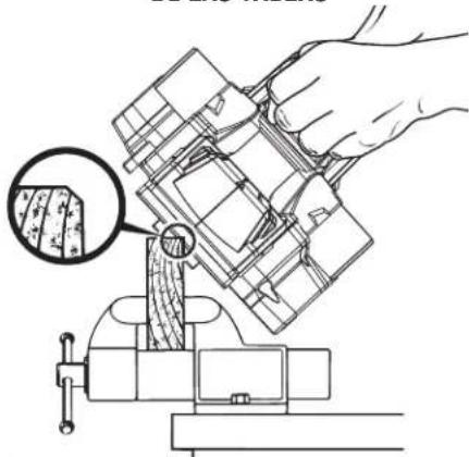
natural_image
Line drawing of a hand using a tool to adjust or install a mechanical component, with a magnified inset showing a textured surface detail (no text or symbols present)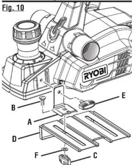
A - Bracket (support, soporte)
B - Carriage head bolt (boulon traversant, perno de cuello cuadrado)
C - Knob nut (écrou à bouton, tuerca de la perilla)
D - Edge guide (guide, guía)
E - Knob bolt (boulon à bouton, tornillo de la perilla)
F - Washer (rondelle, arandela)
Fig. 11
PLANING EDGES
RABOTAGE DE CHANTS
CEPILLADO DE CANTOS
natural_image
Technical line drawing of a surveying instrument with no visible text or symbolsFig. 12
MAKING RABBET CUTS
FEUILLURES
REBAJADO DE CANTOS
natural_image
Technical line drawing of a mechanical assembly (no text or symbols)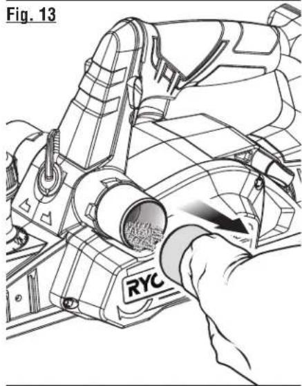
natural_image
Technical line drawing of a mechanical device with a hand operating the tool (no text or symbols present)Fig. 14
A - Blade wrench (clé à lame, llave de las cuchillas)
B - Screw (vis, tornillo)
C - Blade holder (support de lame, portacuchillas)
D - Spring-loaded blade guard (le protège-lame à ressort, la protección de la hoja cargada a resorte)
E - Loosen (desserrer, para aflojar)
F - Tighten (serrer, apriete)
Fig. 15
A - Blade (lame, cuchilla)
B - Screwdriver (tournevis, destornillador)
Fig. 16
natural_image
Illustration of a hand holding a tool with an arrow indicating direction (no text or symbols)Fig. 17
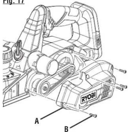
A - Belt cover (carter de courroie, cubierta de la correa)
B - Screw (vis, tornillo)
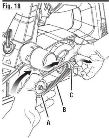
A - Large pulley (grande poulie, polea grande)
B - Belt (courroie, correa)
C - Small pulley (petite poulie, polea pequeña)
To request service, purchase replacement parts, locate an Authorized Service Center and obtain Customer or Technical Support: Visit www.ryobitools.com or call 1-800-525-2579 If any parts or accessories are damaged or missing, do not return this product to the store. Call 1-800-525-2579 for immediate service.
Please obtain your model and serial number from the product data plate. This product is covered under a 3-year limited Warranty. Proof of purchase is required.
MODEL NUMBER ____ SERIAL NUMBER ____
RYOBI is a registered trademark of Ryobi Limited and is used pursuant to a license granted by Ryobi Limited.