
Sani 400 Mirror Wifi - Heating Eurom - Free user manual and instructions
Find the device manual for free Sani 400 Mirror Wifi Eurom in PDF.

| Product type | Smart heating mirror wall radiator |
| Model | Sani Mirror 400 Wi-Fi |
| Brand | Eurom |
| Power | 400 W |
| Power supply | 220-240 V ~ 50 Hz |
| Dimensions (W x H x D) | 50 x 70 x 5 cm |
| Weight | 8.2 kg |
| Protection rating | IP24 |
| Protection class | Class I |
| Installation zone (bathroom) | Zone 3 only |
| Connectivity | Wi-Fi 2.4 GHz and Bluetooth |
| App | Eurom Smart (iOS/Android) |
| Functions | Adjustable thermostat (0-37 °C), countdown timer (0-24 h), weekly programming via app |
| Display | LED screen with Wi-Fi and temperature indicators |
| Material | Tempered glass panel |
| Mounting | Wall-mounted, fixed |
| Safety distance | 50 cm ceiling, 20 cm side walls, 10 cm floor, 50 cm front |
| Overheat protection | Yes, automatic shutdown |
| Open window detection | Yes |
| Maintenance | Clean with a soft, damp cloth, do not immerse |
| Warranty | 60 months |
| Country of manufacture | Netherlands |
Frequently Asked Questions - Sani 400 Mirror Wifi Eurom
User questions about Sani 400 Mirror Wifi Eurom
0 question about this device. Answer the ones you know or ask your own.
Ask a new question about this device
Download the instructions for your Heating in PDF format for free! Find your manual Sani 400 Mirror Wifi - Eurom and take your electronic device back in hand. On this page are published all the documents necessary for the use of your device. Sani 400 Mirror Wifi by Eurom.
USER MANUAL Sani 400 Mirror Wifi Eurom
natural_image
Blank white image with no visible content, text, or symbolsModel: Product code:
Sani Mirror 400 Wi-Fi 350418
Sani Mirror 400 Wi-Fi (Swiss plug) 350425
Sani Mirror 600 Wi-Fi 350432
Sani Mirror 600 Wi-Fi (Swiss plug) 350449
Figuur 4.
Figuur 7.

Figuur 8.
Figuur 9.
Installatie

WAARSCHUWING
Figuur 10.
Werking

WAARSCHUWING
Figuur 11.
De afteltimer instellen
Figuur 12.
Slimme timer
natural_image
Symbol of a recycling symbol: a crossed-out trash bin and a solid recycling triangle (no text or labels)Please read and understand these safety instructions. Incorrect use can cause injury and will void EUROM's warranty.

WARNING
- The heater must not be used if the glass panels are damaged.
- Plastic bags can be dangerous. To avoid danger of suffocation, keep this bag away from babies and children.

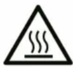
CAUTION
Some parts of this product can become very hot and cause burns. Particular attention has to be given where children and vulnerable people are present.
WARNING
In order to avoid overheating, do not cover the heater.
- Children of less than 3 years should be kept away unless continuously supervised.
- Children aged from 3 years and less than 8 years shall only switch on/off the appliance provided that it has been placed or installed in its intended normal operating position and they have been given supervision or instruction concerning use of the appliance in a safe way and understand the hazards involved. Children aged from 3 years and less than 8 years shall not plug in, regulate and clean the appliance or perform user maintenance.
- This appliance can be used by children aged from 8 years and above and persons with reduced physical, sensory or mental capabilities or lack of experience and knowledge if they have been given supervision or instruction concerning use of the appliance in a safe way and understand the hazards involved. Children shall not play with appliance. Cleaning and user maintenance shall not be done by children without supervision.
- Heater must not be located immediately below a socket-outlet.
- If the supply cord is damaged, it must be replaced by manufacturer, its service agent or similarly qualified persons in order to avoid a hazard.
- Heater is to be installed so that switches and other controls cannot be touched by a person in the bath or shower.
The device is equipped with an overheating protection, which switches it off automatically in case of internal overheating. Switch the device off, unplug the power plug, remove the source of overheating, let it cool down and use as normal. Do not use the device if the source of overheating cannot be traced or if the problem persists, but always contact your supplier.
This device is not suitable for use by persons with a physical, sensory or mental disability, or lack of experience and knowledge (including children). Keep the device out of reach of children, unqualified persons and pets. Never leave the device unattended while it is in operation.
Placement in bathroom
This device is safe to use in the bathroom when the device is mounted:
- in zone 3 of a toilet room or bathroom with a bath, shower with screen or shower without screen, see Figure 13;
• in a fixed position;
•out of reach for operation by a person in a bath or shower.
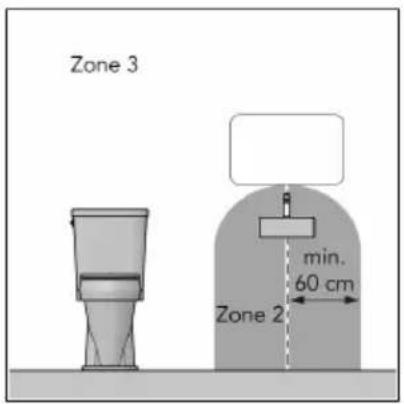
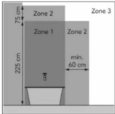
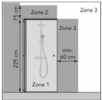
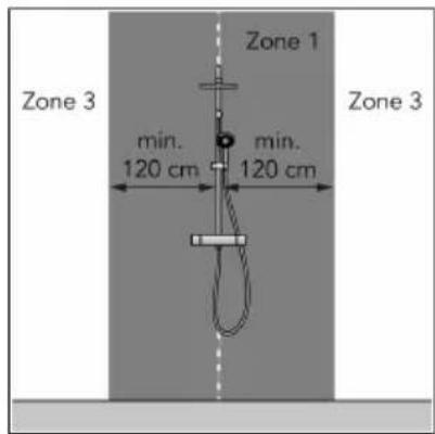
Figure 13.
General safety instructions

WARNING
- Prevent splashing water on or in the device.
- Do not immerse any part of the device in water or other liquids.
- Never insert fingers or other objects into the openings of the device.
- Do not expose the device to strong vibrations or mechanical stress.
WARNING
The device becomes very hot during use. Do not touch the device during use or within five minutes after use.

CAUTION
Do not cover the device during usage or after use while the device is still hot. To reduce the risk of fire, keep textiles, curtains, tent canvasses and other flammable material at a minimum distance of 1 meter from the device.
Safety during operation
WARNING
Do not use the device:
• outdoors or in a small space (< 7 m ^3 );
- lying, leaning or standing;
- if any parts are dirty or wet;
•near large objects, like behind a door, under a shelf or near a cupboard;
•near a water source in zone 1 and zone 2, like a bath, shower or swimming pool;
- near or in a dusty and dirty environment, like a construction site;
•near flammable materials, liquids or fumes, e.g. in a shed, stable or green house;
•near other heat sources and open fire;
•near, under or facing a socket outlet;
- with an appliance that automatically switches the device on, such as a timer, dimmer or any other device.
If the device, the electric cable or plug shows damage or is malfunctioning, immediately take the appliance out of use and disconnect the power supply.

Warranty
EUROM offers a 60-month warranty on this device from the date of purchase. The warranty does not cover wear and tear from normal use. The warranty expires if a defect is the result of unintentional or careless use of the device. The manufacturer, importer and supplier are not liable for incorrect connections.
Introduction
Thank you for choosing this EUROM device. You have purchased a quality device that you will enjoy for many years. Using this device with respect and care will reduce the risk of personal injury or material damage.

CAUTION
It is important to read and understand this instruction manual before assembling, installing and using the device.
This manual describes the correct and safe use of this device. Keep this manual for future reference. The manual is an essential part of the device and must be given to the new owner upon resale or exchange. This manual has been compiled with the utmost care. Nevertheless, we reserve the right to improve and adjust this manual at any time. The images used may differ.
The following symbols and terms are used in this manual to alert the reader to safety issues and important information:

WARNING
Indicates a hazardous situation which, if the safety instructions are not followed, can lead to injuries to the operator or bystanders, light and/or moderate damage to the product or to the environment.

CAUTION
Indicates a hazardous situation which, if the safety instructions are not followed, can lead to light and/or moderate damage to the product or to the environment.
Identification
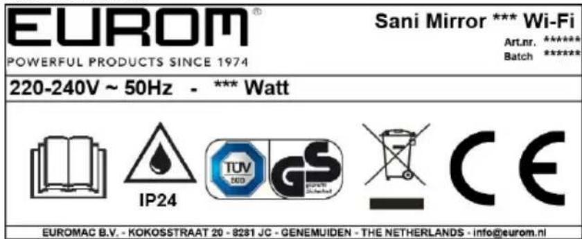
Figure 14.
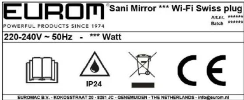
Figure 15.
Specifications
| Type Sani Mirror 400 Wi-Fi Sani Mirror 600 Wi-Fi | |
| Product size: 5 x 50 x 70 cm 5 x 80 x 60 cm | |
| Weight: 8.2 kg 11.2 kg | |
| Voltage: 220 - 240V~ / 50Hz 220 - 240V~ / 50Hz | |
| Power: 400W 600W | |
| Protection rating: IP24 IP24 | |
| Protective class: Class I Class I |
Hereby, Euromac b.v. declares this product is in compliance with Directive 2014/53/EU.
The full text of the EU declaration of conformity is available at the following internet address: www.eurom.nl/declaration-of-conformity.
•Wi-Fi and Bluetooth Frequency Band: 2.4 \~ 2.4835GHz
• Maximum radio-frequency power transmitted in this frequency band(s):
°Wi-Fi: 17.5dBm
- Bluetooth: 6.5dBm
Description
The Sani Mirror Wi-Fi is an easy-to-use electric bathroom heater for use in zone 3 of the bathroom (see Placement in bathroom). The Sani Mirror Wi-Fi can be used with the Eurom Smart App.
Unboxing
- Main device
- ON/OFF switch
- Control panel and LED display
- Power plug

Figure 16.
Control panel and display
- Wi-Fi indication
- Timer button
- Square bracket
- Minus button
- Plus button
- Temperature indication
The LED-screen will extinguish automatically after ± 15 seconds, the square brackets remain visible. Touch the device between the square brackets (Figure 17, pos. 3) to light it up again.
![6 20°C 5 [+] 4 -] 3 2 Time 1 Wi-Fi](/content/2026/04/696240/images/ddb798fd1e9073ec0af9dbe1a1bf0bf88af0af181b4c873f3efd623dd5fa3542.jpg)
Figure 17.
Transport and storage
- Clean the device before storing it.
- Transport the device in an upright position.
- Store the device in an upright position, in its original packaging, in a cool, dry and dust-free area.
Installation
The device is packed in one box. Remove all packaging material and check that the device is not damaged. Do not use the device if it is damaged, but always contact your supplier. Keep the packaging for safe storage and transport.
Wall mounting

WARNING
The wall used for mounting must be made from non-flammable material and should be able to withstand a minimum temperature of 125^ C.

CAUTION
Make sure to use suitable fastening materials, depending on the surface. Never block the space between the device and the wall.
- Place the device on a non-flammable and solid wall.
-
Place the device with a minimum distance (Figure 18) of:
-
50 cm from the ceiling;
- 20 cm from the side walls;
- 10 cm from the floor;
-
50 cm clearance on the front side.
-
Do not mount the device:
-
immediately below a socket outlet;
• on a ceiling or roof.
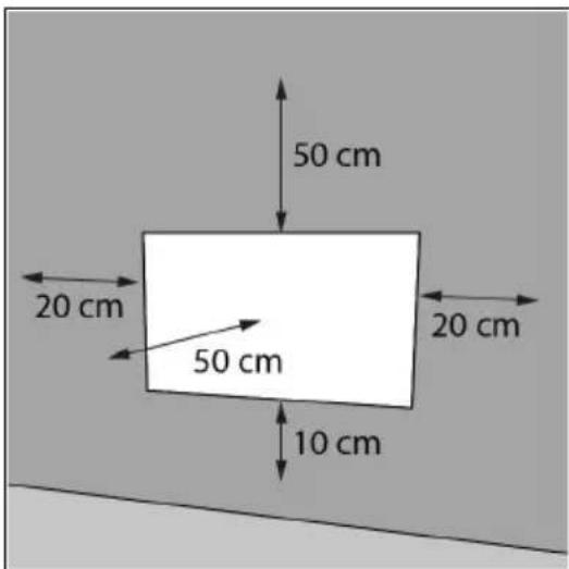
Figure 18.
- Place the wall bracket (Figure 19, pos. 1) against the wall and mark the five holes.
- Drill five holes at the marked spots.
- Place plugs (Figure 19, pos. 3).
- Screw and tighten the wall bracket to the wall with five large screws (Figure 19, pos. 2) using a Phillips screwdriver (Figure 19, pos. 4).
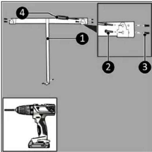
Figure 19.
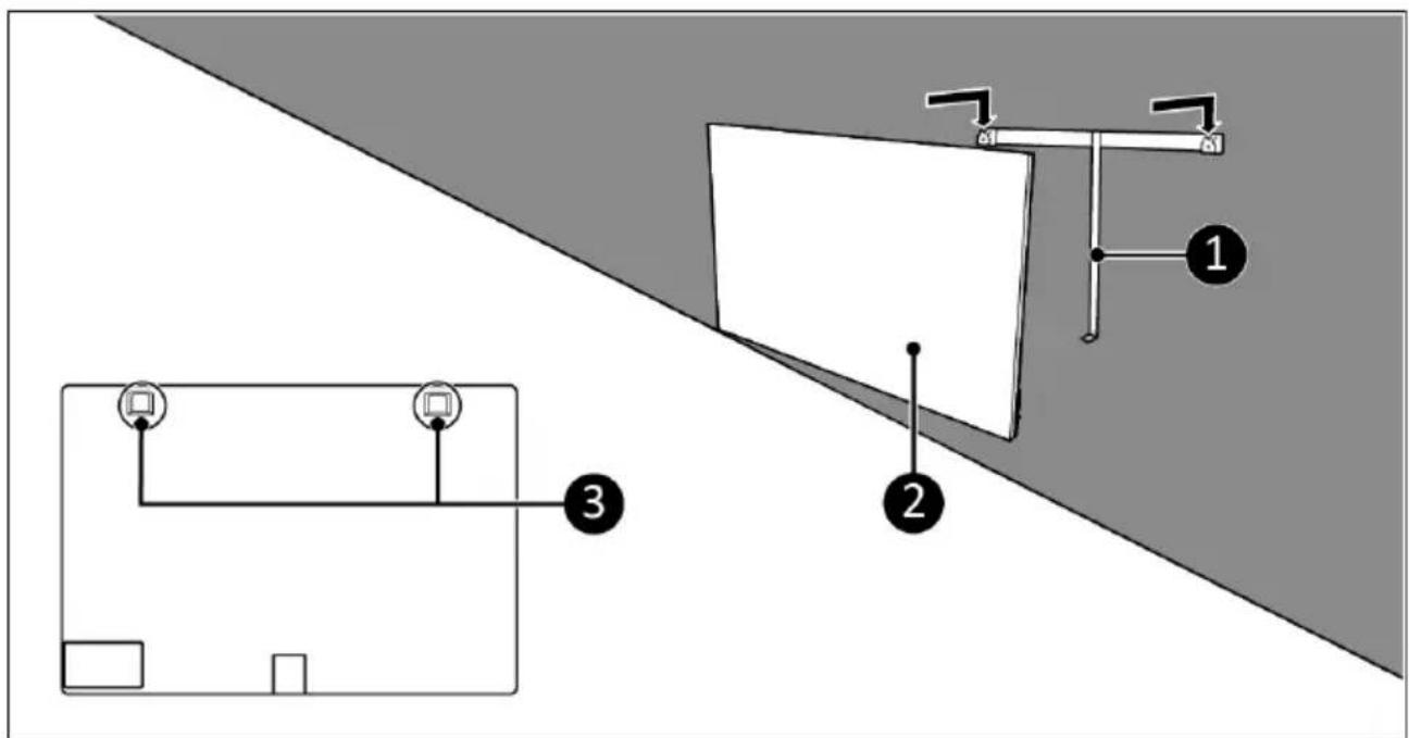
Figure 20.
- Place the device brackets (Figure 20, pos. 3) over the wall bracket (Figure 20, pos. 1).
- Slide the device (Figure 20, pos. 2) into the openings of the wall bracket.
- Screw and tighten the device (Figure 21, pos. 1) with a small screw (Figure 21, pos. 3) to the wall bracket using a Phillips screwdriver (Figure 21, pos. 2).
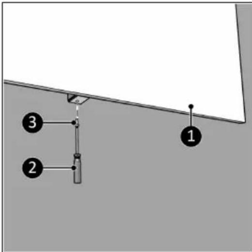
Figure 21.
Installation

WARNING
- Do not put the power plug into the wall socket before the device is mounted or placed correctly.
- Do not use an extension cable; this can cause overheating and fire. If using an extension cable is unavoidable, make sure it is undamaged and earthed. Use an extension cable with a minimum power of 800 Watt. Always unwind the extension cable completely to prevent overheating.

CAUTION
Make sure that the main voltage is the same as indicated on the identification label of the device. All electrical connections must stay dry under all circumstances.
- Make sure the device is correctly mounted.
- Make sure the ON/OFF switch is in the OFF position (Figure 22, pos. 2).
- Place the power plug (Figure 22, pos. 1) into an earthed wall socket that is easily accessible. Use an earthed wall socket with a minimum power of 800 Watt.
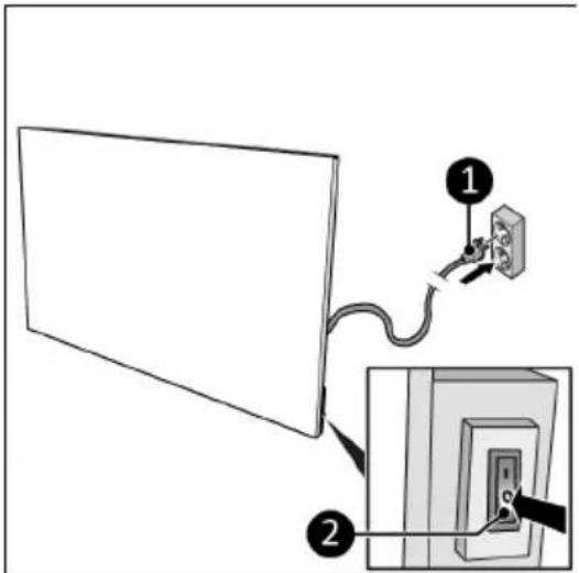
Figure 22.
Operation

WARNING
Before every use, make sure that:
•you operate the device with dry hands;
•the device is clean and dry;
•the device is not damaged;
•the device is not covered or blocked;
•the device is securely mounted.

CAUTION
When the device is turned on or off, it may emit a sound. This is the material expanding and shrinking during heating and cooling down.
- Set the ON/OFF switch to the ON position (Figure 23, pos. 1).
- The control panel and display (Figure 23, pos. 2) will light up.
- Press the Plus or Minus button to set the desired temperature, from 0 °C to 37 °C. The device starts heating when the set temperature is higher then the ambient temperature.
- The display will first show the set temperature for 3 seconds followed by the ambient temperature.
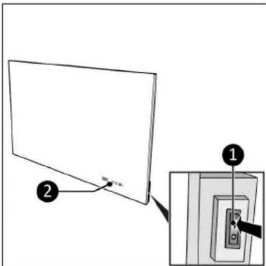
Figure 23.
Set the countdown timer
- Press the Timer button once or multiple times to set the countdown timer, from 00 to 24 in whole hours.
Eurom Smart App

CAUTION
It is recommended to switch on Bluetooth on your smart phone when connecting your Eurom device for the first time. Doing so will make connecting quicker and easier.
The device can be operated using an app on a smartphone or tablet. The Eurom Smart App can be used to:
- switch the device on and off;
•regulate the temperature.
The app can also be used to set twenty on and off timer settings daily, on the weekly timer.
- Open the Eurom Smart App manual with the QR code (Figure 24) or go to www.eurom.nl/nl/manuals.
- Complete the steps in the Eurom Smart App manual.
°When the device is connected with Wi-Fi, the Wi-Fi symbol appears on the screen.
°If the Wi-Fi symbol is blinking there is no connection.
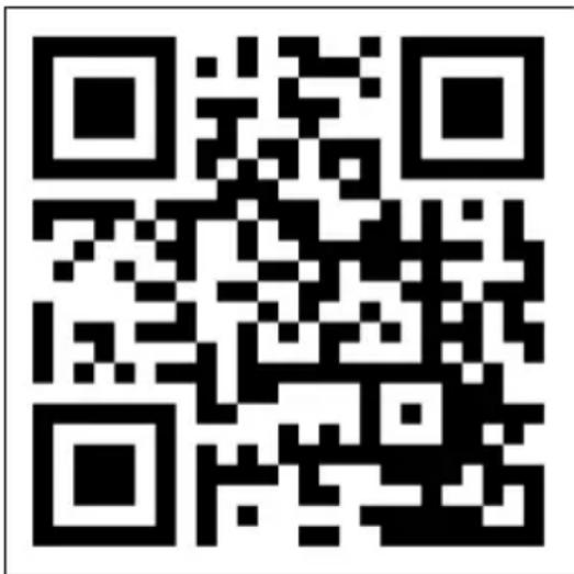
Figure 24.
Smart Timer
- Create a schedule with days and times in the Eurom Smart App. Timer settings set in the app:
°will be stored on the device;
◦will not be visible on the device;
°will remain available if Wi-Fi disconnects;
•will remain available if the device is switched off or unplugged;
°can only be removed via the app.
- Check the data in the app regularly.
Reset Wi-Fi connection
- Press and hold the Timer button until a beep sounds. Existing connections will be deleted. The Wi-Fi symbol will start blinking and a new connection can be made.
Switch off Wi-Fi connection
- Press and hold the Minus button until a beep sounds. The Wi-Fi is switched off and the Wi-Fi symbol will disappear from the screen.
- Press and hold the Minus button until a beep sounds. The Wi-Fi is switched on and the Wi-Fi symbol will appear on the screen.
After operation

CAUTION
Do not use the power cable to unplug or carry the device. Do not wind the power cable too tightly or in sharp corners. Do not wrap the power cable around the device.
- Make sure the ON/OFF switch is in the OFF position.
- Disconnect the power plug from the power outlet.
- Let the device cool down before touching it.
- Wind the power cable.
Maintenance

WARNING
Do not perform any repairs or modifications to this device.
Maintenance and repairs must be carried out by a EUROM authorized professional. If the electric cable and/or electric plug is damaged, it should be replaced by the manufacturer or its service employee or persons with similar qualifications to prevent risks.
Cleaning
WARNING
The device becomes very hot. Make sure the device is turned off, unplugged and completely cooled down.

CAUTION
Do not use:
- scouring pads;
- hard brushes;
- flammable, aggressive or chemical cleaning products.
Prevent water from entering the device. Do not immerse any part of the device in water or other liquids.
It is recommended to clean the device after each use and prior to storage.
- Wipe the device with a damp, clean, soft, lint-free cloth or a soft brush.
- Let the device dry completely prior to use and storage.
This marking indicates that this product should not be disposed of with other household waste throughout the EU. To prevent possible harm to the environment or human health from uncontrolled waste disposal, recycle it responsibly to promote the sustainable reuse of material resources. To return your used device, please use the return and collection systems or contact the retailer where the product was purchased. They can take this product for environmentally safe recycling.
Attachments
| Information requirements for electric local space heaters | |||||
| Model identifier: Sani Mirror 400 Wi-Fi | |||||
| Item Symbol Value Unit Item | Unit | ||||
| Heat output Type of heat output/room temperature control (select one) | |||||
| Nominal heat output Pnom 0.400 kW single stage heat output and no room temperature control | no | ||||
| Minimum heat output (indicative) | Pmin 0.00 kW two or more manual stages, no room temperature control | no | |||
| Maximum continuous heat output | Pmax,c 0.400 kW with mechanic thermostat room temperature control | no | |||
| Power consumption with electronic room temperature control no | |||||
| In off mode | Po | 0.00 | W | electronic room temperature control plus day timer | no |
| In standby mode | Psm | N.A. | W | electronic room temperature control plus week timer | yes |
| In idle mode | Pidle | 0.73 | W | Other control options (multiple selections possible) | |
| In network standby | Pnsm | 0.73 | W | room temperature control, with presence detection | no |
| Standby mode with display of information or status | no | room temperature control, with open window detection | yes | ||
| Seasonal space heating energy efficiency in active mode | ηS,on 94.0 % | distance | control option yes | ||
| adaptive start control | no | ||||
| working time limitation | yes | ||||
| black bulb sensor | no | ||||
| self-learning functionality | no | ||||
| control accuracy | no | ||||
| Contact details | Eurom - Kokosstraat 20 - 8281 JC - Genemuiden - The Netherlands | ||||
| Model identifier: Sani Mirror 600 Wi-Fi | |||||
| Item Symbol Value Unit Item | Unit | ||||
| Heat output Type of heat output/room temperature control (select one) | |||||
| Nominal heat output Pnom 0.600 kW single stage heat output and no room temperature control no | |||||
| Minimum heat output (indicative) | Pmin 0.00 kW two or more m manual stages, no room temperature control no | ||||
| Maximum continuous heat output | Pmax,c 0.6s00 kW with mech anic thermostat room temperature control no | ||||
| Power consumption with electronic room temperature control no | |||||
| In off mode | Po | 0.00 | W | electronic room temperature control plus day timer | no |
| In standby mode | Psm | N.A. | W | electronic room temperature control plus week timer | yes |
| In idle mode | Pidle | 0.73 | W | Other control options (multiple selections possible) | |
| In network standby | Pnsm | 0.73 | W | room temperature control, with presence detection | no |
| Standby mode with display of information or status | no | room temperature control, with open window detection | yes | ||
| Seasonal space heating energy efficiency in active mode | ηS,on 94.0 % | distance | control option yes | ||
| adaptive start control | no | ||||
| working time limitation | yes | ||||
| black bulb sensor | no | ||||
| self-learning functionality | no | ||||
| control accuracy | no | ||||
| Contact details | Eurom - Kokosstraat 20 - 8281 JC - Genemuiden - The Netherlands | ||||
Abbildung 28.
Abbildung 31.

Abbildung 32.
Abbildung 33.
Installation

WARNUNG
Abbildung 34.
Betrieb

WARNUNG
Abbildung 35.
Abbildung 36.
Intelligenter Timer
Figure 40.
Figure 43.

Figure 44.
Figure 45.
Installation

AVERTISSEMENT
Figure 46.
Utilisation

AVERTISSEMENT
Figure 47.
Figure 48.
Minuterie intelligente
natural_image
Symbolic image of a recycling bin with a crossed-out line and a solid recycling triangle (no text or labels)Figur 52.
Figur 55.

Figur 56.
Figur 57.
Installation

WARNING
Figur 58.
Drift

WARNING
Figur 59.
Figur 60.
Smart timer
Figur 64.
Kontrolpanel og display
- Indikator for Wi-Fi
- Timerknap
- Firkantede parenteser
- Minusknap
- Plusknap
- Indikator for temperatur
Figur 67.

Figur 68.
Figur 69.
Installation

ADVARSEL
Figur 70.
Betjening

ADVARSEL
Figur 71.
Figur 72.
Smart Timer
natural_image
Symbolic image of a recycling bin with crossed lines and a recycling symbol (no text or labels)Obrázek 76.
Obrázek 79.

Obrázek 80.
Obrázek 81.
Instalace

VAROVÁNÍ
Obrázek 82.
Provoz

VAROVÁNÍ
Obrázek 83.
Obrázek 84.
Chytrý časovač
natural_image
Symbolic representation of a recycling machine with no text or labelsObrázok 88.
Obrázok 91.

Obrázok 92.
Obrázok 93.
Inštalácia

UPOZORNENIE
Obrázok 94.
Prevádzka

UPOZORNENIE
Obrázok 95.
Obrázok 96.
natural_image
Symbol of recycling with a trash bin and recycling symbol (no text or labels)Figura 100.
Figura 103.

Figura 104.
Figura 105.
Instalare

AVERTISMENT
Figura 106.
Functionare

AVERTISMENT
Figura 107.
Figura 108.
Temporizator intelligent
natural_image
Symbol of recycling (no text or numbers present)
- Installatie
- WAARSCHUWING
- Werking
- De afteltimer instellen
- Slimme timer
- WARNING
- CAUTION
- Placement in bathroom
- General safety instructions
- Safety during operation
- Warranty
- Introduction
- Description
- Unboxing
- Control panel and display
- Transport and storage
- Installation
- Wall mounting
- Operation
- Set the countdown timer
- Eurom Smart App
- Smart Timer
- Reset Wi-Fi connection
- Switch off Wi-Fi connection
- After operation
- Maintenance
- Cleaning
- Abbildung 32.
- WARNUNG
- Betrieb
- Intelligenter Timer
- AVERTISSEMENT
- Utilisation
- Minuterie intelligente
- Drift
- Kontrolpanel og display
- ADVARSEL
- Betjening
- Obrázek 80.
- Instalace
- VAROVÁNÍ
- Provoz
- Chytrý časovač
- Obrázok 92.
- Inštalácia
- UPOZORNENIE
- Prevádzka
- Instalare
- AVERTISMENT
- Functionare
- Temporizator intelligent
Brand : Eurom
Model : Sani 400 Mirror Wifi
Category : Heating