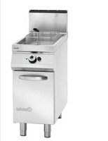
2959961 - Deep fryer BARTSCHER - Free user manual and instructions
Find the device manual for free 2959961 BARTSCHER in PDF.


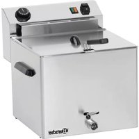
| Product type | Professional gas fryer |
| Brand | Bartscher |
| Model | 2959961 |
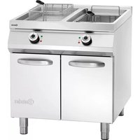
| Number of vats | 1 vat (standard version, also available in 2-vat version) |
| Material | Stainless steel |
| Power supply | Single-phase 230 V / 50 Hz (integrated disconnector) |
| Gas type | Natural gas or propane (adaptable according to nameplate) |
| Ignition | Piezoelectric |
| Temperature range | Adjustable up to approx. 180 °C (recommended frying temperature 160-180 °C) |
| Safety devices | Thermocouple (gas cut-off if flame goes out), safety thermostat (cut-off in case of overheating), gas shut-off valve |
| Included accessories | Lid, frying basket, oil tank, extractor extension, extractor cover, extractor grid |
| Cleaning and maintenance | Daily cleaning of surfaces and vat; drain oil after each use; do not clean with water jet |
| Intended use | Frying food products in professional catering establishments |
| Installation | Minimum distance of 5 cm from wall; adjustable feet height; gas connection by certified technician |
| Spare parts | Burner nozzles, flame nozzles, solenoid valve, thermocouple, safety thermostat, baskets, vats |
| Repairability | Work to be carried out by qualified personnel only; use of original spare parts |
Frequently Asked Questions - 2959961 BARTSCHER
User questions about 2959961 BARTSCHER
0 question about this device. Answer the ones you know or ask your own.
Ask a new question about this device
Download the instructions for your Deep fryer in PDF format for free! Find your manual 2959961 - BARTSCHER and take your electronic device back in hand. On this page are published all the documents necessary for the use of your device. 2959961 by BARTSCHER.
USER MANUAL 2959961 BARTSCHER
- TABLE OF CONTENTS 1
- INDEX 2
- SAFETY 3
- GENERAL INFORMATION AND WARNINGS 4
4.1. General guidelines 4
4.2. Description of the appliance 4
4.3. Protection devices 5
4.4. Replacement of components 5
4.5. Rating plate 6
4.6. Elements and accessories 6
- USE AND OPERATION 7
5.1.Description of the controls 7
5.2. Burner ignition 7
5.3. Filling and emptying containers 8
5.4. Guidelines on how to use the appliance 9
6.CLEANING AND MAINTENANCE 9
6.1. Guidelines on cleaning and maintenance 9
6.2. Proper maintenance 9
6.3. Cleaning the container 10
- TROUBLESHOOTING 10
- INSTALLATION 11
8.1. Packaging and unpacking 11
8.2. Installation (service technician) 11
8.3. Installation of the smoke extractor (Service technician) 12
8.4. Gas connection (Service technician) 12
8.5. Electrical connection (Service technician) 12
8.6. Extraction of fumes 13
8.7. Installation of the appliance in a line 13
8.8. Gas supply (Service technician) 13
8.9. Inspection (Service technician) 14
- SETTINGS 14
9.1. Setting of the gas solenoid valve (Service technician) 14
9.2. Replacement of the burner nozzle (Service technician) 15
9.3. Replacement of the flame nozzle (Service technician) 15
10.APPLIANCE DISPOSAL 16
ATTACHMENTS I
2. INDEX
A
APPLIANCE DISPOSAL 16
B
Burner ignition 7
C
Cleaning the container 10
D
Description of the appliance 4
Description of the controls 7
E
Electrical connection 12
Elements and accessories 6
Extraction of fumes 13
G
Gas connection 12
Gas supply 13
General guidelines 4
Guidelines on cleaning and maintenance 9
Guidelines on how to use the appliance 9
1
Inspection 14
Installation 11
Installation of the appliance in a line 13
Installation of the smoke extractor 12
P
Packaging 11
Proper maintenance 9
Protection devices 5
R
Rating plate 6
Replacement of components 5
Replacement of the burner nozzle 15
Replacement of the flame nozzle 15
S
SAFETY 3
Setting of the gas solenoid valve 14
T
TROUBLESHOOTING 10
U
Unpacking 11
3. SAFETY

Read carefully the guidelines and instructions in the instruction manuals. Are you use the appliance.
The instruction manual contains general information on how to safely use and maintain the appliance.
Retain the manual for future reference.
The manufacturer took extra care when designing and manufacturing to prevent any safety or health hazard to the personnel operating the appliance.
Please read carefully the guidelines in the instruction manual and instructions placed directly onto the appliance. Above all, observe all the safety instructions.
Do not intervene in or remove the protective devices installed in the appliance. Noncompliance may lead to severe safety and health hazard against people. We recommend to perform a few tests to know the layout and main functions of the control panel, particularly those to switch the appliance on and off.
The appliance is intended only for the use it has been designed for and any other use is considered as the use not in compliance with the intended use.
The manufacturer is not liable for material damage or damage to person caused by misapplication or incorrect application of the appliance.
Any maintenance work that requires special technical licence or special skills may be performed by qualified personnel only.
To provide hygiene and protect foods from dirt, all the elements that have direct or indirect contact with the foods and all border areas must be thoroughly cleaned. Use only the cleaning agents intended for use in contact with food and avoid using flammable agents or harmful to health.
After each use of the appliance make sure that all the heating elements and control elements have been switched off and the cable unplugged.
In case of prolonged interval in using the appliance disconnect all power supply cables and thoroughly clean the inside and outside elements of the appliance.
To avoid a risk of fire, check that the oil level is not below the minimum level marked in the container.
The oil change is recommended when its colour is dark or when the smoke occurs in the temperature 160^ - 180^ . The frequently used oil has low ignition temperature.
Remember that the food that is too moist, or the load that is too high may cause the oil to boil unexpectedly.
Use the oils or oil mixtures that are intended for use in deep fryers.
Pay extra attention to the floor around the appliance that may be slippery.
You must not clean the appliance with the direct stream of water.
4. GENERAL INFORMATION AND WARNINGS
4.1. General guidelines
The manual has been edited by the manufacturer to provide the authorized personnel with the information necessary to work with the appliance. We recommend the intended readers to read the manual carefully and comply with the information. By reading the information contained in the manual, hazards against people health and safety may be prevented.
Retain the manual in an easily available place throughout the time of use of the appliance to have access and refer to the required information at any time.
Special symbols, described below, have been used to stress important information or draw attention to essential data:
Caution - warning

Indicate important safety
instructions. You should acquire the proper conduct to prevent hazard against people health and safety or not to cause any damage.
Important

Indicate essentials technical data that cannot ignore.
4.2. Description of the appliance
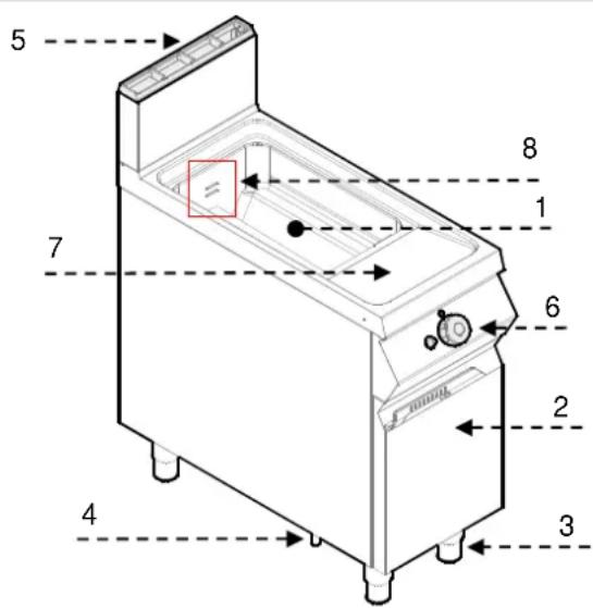
The appliance defined as the deep fryer has been designed and manufactured with the intended use to fry food in commercial food outlets. There is one or two-container option available depending on the need.
1) Container
2) Door
3) Height adjustable feet
4) Gas connection
5) Extractor: Fume extraction.
6) Oil temperature range
7) Burner ignition: Piezo igniter
8) Minimum and maximum oil levels in the container.
4.3. Protection devices

The appliance is equipped with the protection system. The arrangement of protection devices is presented on the drawing.
A. Safety thermocouple: it blocks the gas supply if the flame goes out.
B. Safety thermocouple: it blocks the gas supply in case of overheating.
C. Gas supply valve: to open and close the gas line.

Check daily that the protection devices are used correctly and operational.
If the safety thermocouple is released, the initial work interval of the appliance must be set again in the same position.
- Allow the oil to cool to min. 40^
- Open the door (D).
- Press the safety thermocouple button (B) to activate the gas supply again.
- Close the door (D).
When using the deep fat fryer with two containers, in order to detect the working thermostat, check which burner is working and select the button of the appropriate thermostat.

Do not store any objects inside the frame.
4.4. Replacement of components

Before exchange of the component switch, the existing protection devices.
First of all, switch off the gas valve and prevent access to the appliance, which in the case of activation may lead to unexpected situations endangering the safety and health of people.
If necessary, exchange the used components to the original spare parts.
We are not liable for personal injury or damage to the components that arise due to application of other spare parts than original or intervention into the appliance without the manufacturer's consent that may have altered the safety requirements.
4.5. Rating plate
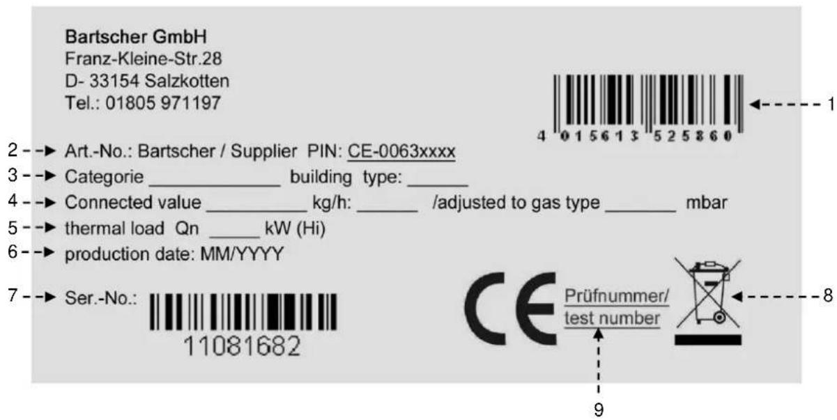
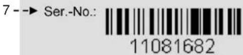
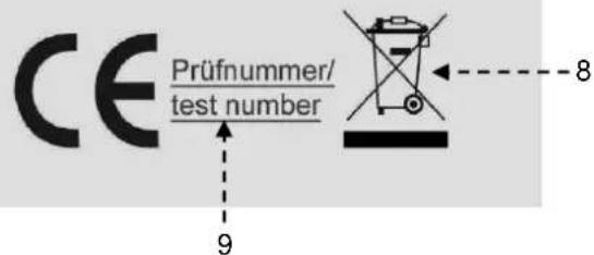
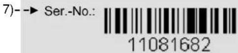
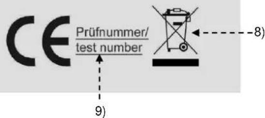
The Rating plate indicated in the drawing is mounted directly onto the appliance. There are all guidelines and information on the plate required for safe use.
1) EAN number
2) Code no./ Model no. / CE certificate no.
3) Category of appliance / type of design
4) Connected value / gas consumption / adjusted to gas type
5) Thermal load
6) Production date
7) Series no.
8) WEEE symbol
9) CE Declaration of Conformity
4.6. Elements and accessories
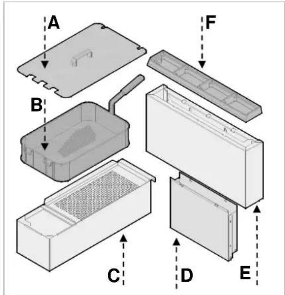
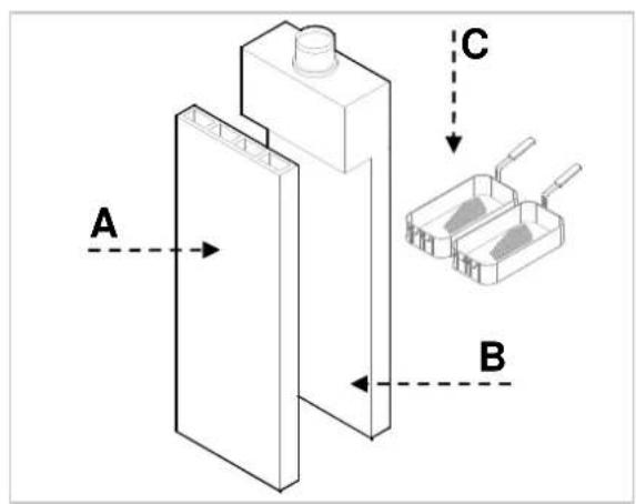
The appliance is delivered with the following elements:
A. Cover
B. Basket
C. Oil container
D. Extractor extension
E. Extractor cover
F. Extractor Grill
On order, we can provide the following accessories:
A. High extractor, B11 type
B. High extractor, B11 type with flow protection
C. Basket construction kit
D. Gas connection set
5. USE AND OPERATION
5.1. Description of the controls.
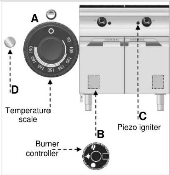
The elements controlling the essential functions are located on the control panel of the appliance.
A) Temperature controller: it regulates the gas supply and changes the oil temperature.
B) Burner controller: it switches the main burner off, including its flames.
C) Piezo igniter: for igniting the ignition flame of the burner.
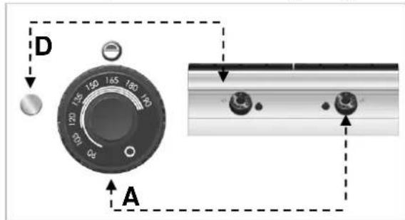
D) Temperature indicator light: until the light is on, the oil has not reached the required temperature. When the oil reaches the required temperature the indicator light goes off.
5.2. Burner ignition
ON
A) Open the gas valve
B) Open the door:
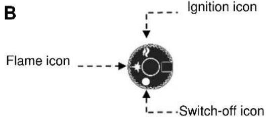
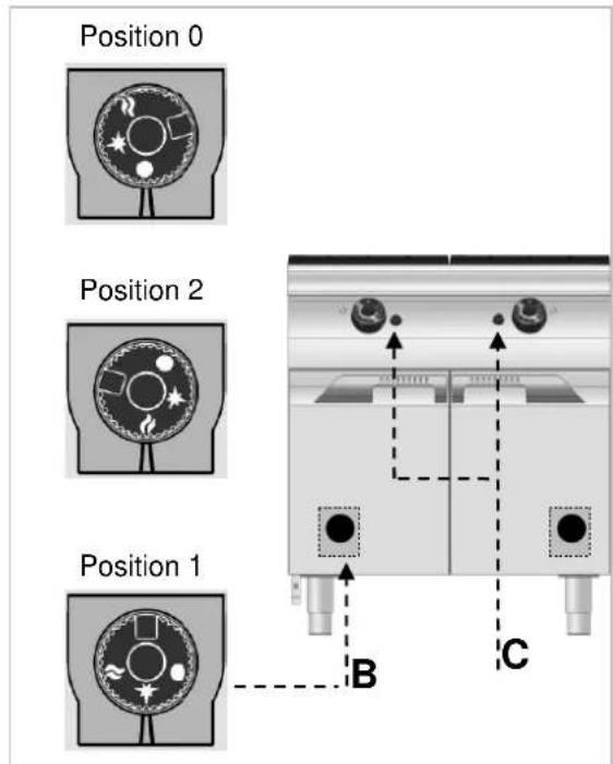
C) Select the controller B and in order to ignite the ignition flame turn it left (position 1): at the same time press the button C to ignite the ignition flame.
D) Hold the controller B for ca. 10 seconds in order to heat up the thermocouple; then release the controller.
E) Activate the controller B for opening the burner gas supply and turn it left (position 2).
F) Close the door.
G) Rotate the controller A in order to set the desired oil temperature.
H) When the oil reaches the required temperature the indicator light D goes off.
OFF
A) In order to switch the burner off, turn the controller A left and set in 0 position; an ignition flame continues burning.
B) Open the door:
C) Activate the controller B for closing the burner gas supply and turn it right (position 0).
D) Close the door.
E) Close the gas valve.
F) Turn on the switch-off to disconnect from the electrical supply.
5.3. Filling and emptying containers

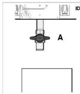
Before filling up the container check that a wet valve A is closed.

Avoid using the appliance with the er filled up with the oil below the marked m level.
We advise against the use of the appliance with the container filled up with the oil above the marked maximum level.

Do not ignite the burner when there is no one container: this may permanently damage appliance.
Do not heat the appliance with the closed cover.
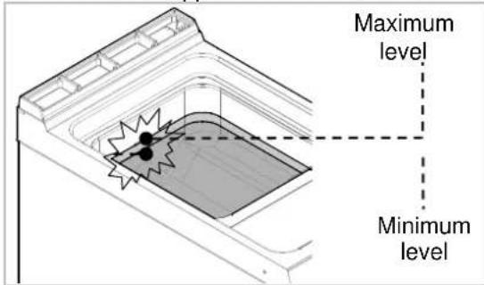
Before emptying the container, leave the device to cool off for 10 -15 minutes to ensure that the oil is cold.
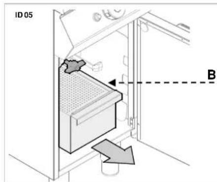
When draining the container follow the instructions below:
A. Open the door
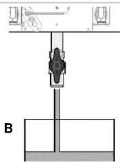
B. Check that the oil container (B) is placed correctly under the outlet valve
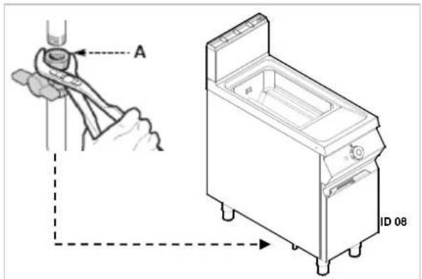
C. Open the outlet valve (A)
D. Pull out the oil drip basin (B).
E. Close the door.
ID 05
OPEN valve
CLOSED valve
Dispose the oil in accordance with the regulations applicable at the place of use of the appliance.
5.4. Guidelines on how to use the appliance
Turn on the automatic switch-off to disconnect from the mains.
- Close the gas valve;
- Thoroughly clean the appliance and adjacent surfaces;
- Apply the Vaseline oil on the stainless steel surfaces.
- Perform all maintenance works;
- When finished using the appliance, always empty the container.

Always empty the containers after use.
To ensure the correct use of the appliance, follow the guidelines below:
Use exclusively the accessories provided by the manufacturer;
Use the frying baskets in the correct way;
Before filling up the container, check that the outlet valve is closed;
Make sure that the oil level is not below the minimum level marked in the container;
Before immersing the basket, check that the oil has reached the set temperature.
Slowly immerse the basket to avoid excessive foam formation.
Frequently filter the oil.
During the short breaks lower the temperature to reduce the oil consumption and slow down ageing the oil.
We recommend the change of oil when its colour is darker or when at the temperature 160^ - 180^ the smoke is forming. The old oil has a low ignition temperature.
Remember that the foods that are too moist or the load that is too high may cause the oil to boil unexpectedly.

Never use the appliance without the container. It may cause total damage to the appliance.
When heating up the deep fryer, always remove the lid.
6. CLEANING AND MAINTENANCE
6.1. Guidelines on cleaning and maintenance

Before you start maintenance works, turn
on all the mounted protective devices. First of all, close the gas valve and prevent access to the
appliance, which in the case of activation may lead to unexpected situations endangering the safety and health of people.
6.2. Proper maintenance
Proper maintenance includes daily cleaning of all components which have contact with food products, and regular maintenance of the burner, nozzle and exhaust pipes.
Careful maintenance ensures the best performance, longer life of the appliance and proper operation of the protective devices.
Never direct the water stream or high pressure jet towards the appliance.
To clean the stainless steel, do not use iron wool or iron brush as they may leave iron particles on the surface that form rust in result of oxidation. Use the wooden or plastic spatula, or soft cleaning sponge to remove the dried remains.
If the appliance is not used for a prolonged time, apply the Vaseline oil on all stainless steel parts and air the room regularly.

Do not use any clearing agents that
contain substances hazardous or harmful to health (solvents, petrol. etc.).
Regularly instruct the specialist personnel to perform the following maintenance works:
Installation pressure and tightness control;
Thermocouples functionality control;
Control of operation of the extractor and possible cleaning;
Control of safety thermostats.
6.3. Cleaning the container
Follow the guidelines.
- Turn off the appliance and leave to cool down.
- Empty the container (Chapter 5.3)
- Remove and clean the frying baskets and basket handles.
- Clean the container inside using the cleaning agent intended for contact with foods.
-
Rinse off with water and empty the container.
-
To remove the remaining cleaning agent the container can be sprinkled with a special agent or vinegar and water solution.
- Rinse off, empty and dry out the container. When finished using the appliance, clean the elements with a proper agent to solve the fat. We recommend to wash the accessories in the dishwasher.
7. TROUBLESHOOTING
Some of the failures can be repaired by the user, others require thorough specialist knowledge.
Such problems may be solved exclusively by the qualified personnel.
| Problem Cause Solution | ||
| Gas smell | The smell is sometimes released when extinguishing the flame. | Close the gas valve and air the room. |
| Ignition flame does not start. | The igniter does not work. | Check the operation of the igniter. Ignite the flame manually. Inform the customer services. |
| Air in the pipes in connection with the long downtime. | ||
| The flame still does not start. | The thermocouple is not hot enough. | Extend the ignition process. Check whether the safety thermocouple is released. |
| The ignition flame burns, but the igniter does not ignite the burner. | Check the working thermostat. If the flame still appears, inform the customer services. | |
| Yellow flame. | Contaminated burner or blocked extractor. | Inform the customer services. |
8. INSTALLATION
8.1. Packaging and unpacking
During unloading and when installing the appliance follow the information from the manufacturer placed directly on the packaging and in this manual.
To lift and transport the product plan to use a fork lift or stacker, and pay attention to even weight distribution to avoid a risk of tilting of the packaging (avoid excessive incline!).

When using the lifting equipment pay.
on to the mains cable, water supply and
age pipes and feet position.
The packaging consists of the carton packaging and wooden pallet. There are symbols printed on the carton packaging that according to the international agreements inform about the regulations to follow when loading and unloading, transporting and storing the appliance.

THIS SIDE UP

FRAGILE

KEEP DRY
8.2. Installation (service technician)
All the stages of the installation must be carefully planned.
The location should be equipped with all supply connections and production waste outlet. The location should also be properly lit and comply with all hygiene and sanitary requirements according to the binding regulations.
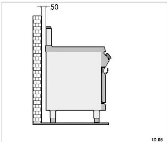
The appliance should be installed leaving the space of at least 5cm to the wall, if this wall is not resistant to the temperature of at least 150^
Locate the appliance in the horizontal position by adjusting the single feet.

To ensure the correct operation of the device, the appliance must be installed and used in the thoroughly ventilated room only.
Internal installation of the gas supply and the rooms in which the appliance is housed, must comply with the local regulations applicable in the country in which the appliance is used (Regulation of 12 June 96 and UNI-CIG 87/23).
When collecting the goods check if the packaging is complete and has not been damaged during transport.
Any damage should be immediately reported to the shipping company.
Unpack the appliance as soon as possible to check if the appliance is not damaged.
Do not use a sharp object to cut the carton box. It may damage the stainless steel inside the box.
Remove the carton packaging from bottom to top.
When unpacked check if the appliance is according to the order.
In case of any difference inform the sales agent immediately.

Do not store the packaging materials
(nylon bags, polystyrene foam, clips ...) in the reach of children!
Remove the protective PVC layer from the out and inner surfaces. If possible, do not use any metal tools.
In order to ensure the proper gas burning in the igniters, the required volume of air, that is ca. 2 cubic meters per hour for every kW of installed power, must be supplied.
8.3. Installation of the smoke extractor (Service technician)
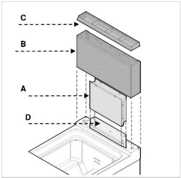
The appliance is supplied with the extractor extension (A) with the cover (B), extractor grill (C) and fixing screws.
Installation is performed as presented on the figure.
Connect the extension (A) with the end of the extractor (D).
Set the cover (B) on the basin level.
Using the screws, connect the cover (B) with the extension (A) in the upper part.
Place the extractor grill (C).
8.4. Gas connection (Service technician)
A gas connection must be performed in compliance with the applicable regulations.
Before connecting the appliance, check the technical data, type of gas, working pressure and flow rate which are provided on the rating plate.
The installation is performed by connecting the connection pipe of the appliance with a pipe of the gas distribution network. A shut-off valve must be installed on the connection to shut the gas supply off if necessary.
If there are significant pressure differences in the gas supply installation, it is recommended to install a pressure regulator.
After the installation, check the gas connection for tightness.

When looking for gas leaks do not use them.
8.5. Electrical connection (Service technician)
Connect the switch-off to the power cord of the appliance, as shown in the figure and on the wiring diagram (see Appendix). Use the H05RN-F cable.
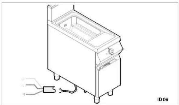
8.6. Extraction of fumes
Installation of the type "A" appliances does not envisage connection to the fume exhaust system, but to the appropriate extraction hood which discharges the fumes to outside.
Installation under the extraction hood (A)
Place the appliance under the extraction hood (1) and attach to the appliance connection a pipe of the size as shown on the figures.
The end of the fume extraction pipe should be located at least 1.8m above the floor.

The appliance's gas supply should be related to the exhaust system: Blocking of the must shut the gas supply off.

The fan must switch on automatically. The gas valve is open.
8.7. Installation of the appliance in a line
To fix the appliance in a line (neighbouring) follow the steps:
Dismantle the control panel, and remove the cast iron frame from the chimney if necessary.
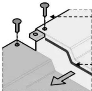
Apply the sealing tape (A) onto the joining sides.
Place the appliances next to each other and in a horizontal position (by adjusting the feet).
Connect the appliances with the joining elements.
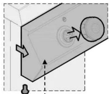
B
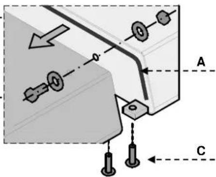
C
8.8. Gas supply (Service technician)
The appliance has been checked by the manufacturer for the type of gas shown on the rating plate. If a different type of gas is used, follow these guidelines.
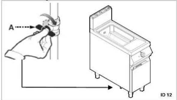
- Close the gas valve (A)
- Replace the burner nozzle (see relevant chapter)
- Replace the nozzle of the ignition flame (see relevant chapter)
- Set a minimum value on the burner gas valve (see relevant chapter)
- If necessary, check the air supply.
- Remove the sticker from the rating plate and apply a new sticker which includes the used gas type (item 13 of the rating plate).
8.9. Inspection (Service technician)
Before starting the appliance the installation check-up should be run to evaluate the working conditions of every single component and recognize any errors.
It is recommended to run the following check-ups:
-
Open the gas valve and check the tightness of connections;
-
Check whether the igniter starts and burns properly.
- Check and adjust, if necessary, the gas pressure and flow rate in Max and Min positions (see chapter)
- Check whether the safety thermostat operates properly.
- Check for gas leakages.
9. SETTINGS

Before setting the appliance, first of all
switch on all the protection devices. In particular deactivate the gas valve and prevent access to
the appliance, which in the case of activation may lead to unexpected situations endangering the safety and health of people.
9.1. Setting of the gas solenoid valve (Service technician)
These settings are required only if the connected type of gas differs from the checked gas, after connecting to the gas supply. Before performing this setting, check whether the gas pressure is compliant with the value of nominal pressure (see table).
Follow the guidelines.
- Close the gas valve.
- Open the door:
- Loosen the screw of pressure connection "OUT" (A) and switch the manometer on.
- Loosen the nut (B).
- Open the gas valve
- Ignite the burner and set the screw B in a position in which the monometer displays the pressure listed in the table (see appendix). Make sure the flame is stable. After the setting tighten the screw.
- Switch the burner off, remove the manometer and set the initial status.
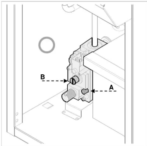
9.2. Replacement of the burner nozzle (Service technician)
Follow the guidelines.
Close the gas valve;
Open the nut (A)
Replace the nozzle (B) with a nozzle intended for the used gas (see appendix).
Finally, set the appliance to the initial status.
Close the door.

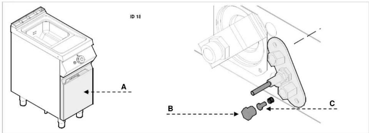
9.3. Replacement of the flame nozzle (Service technician)
Follow the guidelines.
Close the gas valve;
Open the nut (A)
An ignition flame is assigned to the burner.
Loosen the nut (B).Remove the nozzle C and replace it with a nozzle intended for the used gas (see table).
Retighten the nut and set the appliance to the initial status.
Close the door.
10. APPLIANCE DISPOSAL
The appliance is marked in conformity with the European Directive 2002/96/EG WASTE ELECTRICAL AND ELECTRONIC EQUIPMENT (WEEE).

By disposing the appliance in accordance
with the regulations the user contributes towards prevention of adverse effects on environment and health.
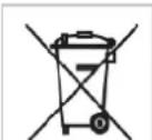
The symbol on the product or attached manual indicates that the product cannot be considered as ordinary household waste and should be transferred to a special collection point
for electrical and electronic appliances for recycling.
Local waste management regulations should be observed.
Further information on procedure, reusing and recycling of the product is available in local offices, waste management unit or with the product sales agent.
1. SOMMAIRE
- SOMMAIRE 1
- INDEX 2
- SECURITE 3
- RÉGLES ET AVERTISSEMENTS GÉNÉRAUX 4
4- - Connected value kg/h: /adjusted to gas type mbar
5-→ thermal load Qn kW (Hi)
6- production date: MM/YYYY
- LIMPEZA E MANUTENÇA 9
6. LIMPEZA E MANUTENÇA
4)- Connected value kg/h: /adjusted to gas type mbar
5)-→ thermal load Qn kW (Hi)
6)- production date: MM/YYYY

- INDEX
- A
- B
- C
- D
- E
- G
- 1
- P
- R
- S
- T
- U
- SAFETY
- Read carefully the guidelines and instructions in the instruction manuals. Are you use the appliance.
- GENERAL INFORMATION AND WARNINGS
- General guidelines
- Caution - warning
- Important
- Description of the appliance
- Protection devices
- Replacement of components
- Rating plate
- Elements and accessories
- USE AND OPERATION
- Description of the controls.
- Burner ignition
- ON
- OFF
- Filling and emptying containers
- Guidelines on how to use the appliance
- CLEANING AND MAINTENANCE
- Guidelines on cleaning and maintenance
- Proper maintenance
- Cleaning the container
- TROUBLESHOOTING
- INSTALLATION
- Packaging and unpacking
- Installation (service technician)
- Installation of the smoke extractor (Service technician)
- Gas connection (Service technician)
- Electrical connection (Service technician)
- Extraction of fumes
- Installation under the extraction hood (A)
- Installation of the appliance in a line
- Gas supply (Service technician)
- Inspection (Service technician)
- SETTINGS
- Setting of the gas solenoid valve (Service technician)
- Replacement of the burner nozzle (Service technician)
- Replacement of the flame nozzle (Service technician)
- APPLIANCE DISPOSAL
- SOMMAIRE
- LIMPEZA E MANUTENÇA
Brand : BARTSCHER
Model : 2959961
Category : Deep fryer