
M18 2623-21 - Plane MILWAUKEE - Free user manual and instructions
Find the device manual for free M18 2623-21 MILWAUKEE in PDF.

| Brand | Milwaukee |
| Model | M18 2623-21 |
| Type | Cordless Planer |
| Voltage | 18 V DC |
| Battery type | M18™ |
| No-load speed | 0 - 14,000 rpm |
| Max planing depth | 2 mm |
| Max rebate depth | 10.7 mm |
| Max planing width | 82 mm |
| Operating temperature | -18°C to 50°C |
| Chamfer capacity | Up to 45° |
| Power supply | M18 lithium-ion battery |
| Recommended charger | M18™ charger |
| Functions | Planing, rebating, chamfering |
| Dust extraction system | Yes, with dust bag or vacuum |
| Edge guide | Included, adjustable in width and angle |
| Blade replacement | Double-edged reversible blades, tungsten carbide |
| Safety | Trigger lock, protective stand |
| Warranty | 5 years (except exceptions) |
| Included accessories | Hex key, edge guide |
Frequently Asked Questions - M18 2623-21 MILWAUKEE
User questions about M18 2623-21 MILWAUKEE
0 question about this device. Answer the ones you know or ask your own.
Ask a new question about this device
Download the instructions for your Plane in PDF format for free! Find your manual M18 2623-21 - MILWAUKEE and take your electronic device back in hand. On this page are published all the documents necessary for the use of your device. M18 2623-21 by MILWAUKEE.
USER MANUAL M18 2623-21 MILWAUKEE
natural_image
Line drawing of a Milwaukee industrial machine with control knob and rotary dial (no text or symbols on the device itself)Cat. No. / No de cat.
2623-20
M18™ 3-1/4" PLANER
RABOTEUSE DE 82 mm (3-1/4") M18™
CEPILLO M18™ DE 82 mm (3-1/4")

WARNING To reduce the risk of injury, user must read and understand operator's manual.
⚠ WARNING Read all safety warnings, instructions, illustrations and specifica-
tions provided with this power tool. Failure to follow all instructions listed below may result in electric shock, fire and/or serious injury. Save all warnings and instructions for future reference. The term "power tool" in the warnings refers to your mains-operated (corded) power tool or battery-operated (cordless) power tool.
WORK AREA SAFETY
- Keep work area clean and well lit. Cluttered or dark areas invite accidents.
- Do not operate power tools in explosive atmospheres, such as in the presence of flammable liquids, gases or dust. Power tools create sparks which may ignite the dust or fumes.
- Keep children and bystanders away while operating a power tool. Distractions can cause you to lose control
ELECTRICAL SAFETY
- Power tool plugs must match the outlet. Never modify the plug in any way. Do not use any adapter plugs with earthed (grounded) power tools. Unmodified plugs and matching outlets will reduce risk of electric shock.
- Avoid body contact with earthed or grounded surfaces, such as pipes, radiators, ranges and refrigerators. There is an increased risk of electric shock if your body is earthed or grounded.
- Do not expose power tools to rain or wet conditions. Water entering a power tool will increase the risk of electric shock.
- Do not abuse the cord. Never use the cord for carrying, pulling or unplugging the power tool. Keep cord away from heat, oil, sharp edges or moving parts. Damaged or entangled cords increase the risk of electric shock.
- When operating a power tool outdoors, use an extension cord suitable for outdoor use. Use of a cord suitable for outdoor use reduces the risk of electric shock.
- If operating a power tool in a damp location is unavoidable, use a ground fault circuit interrupter (GFCI) protected supply. Use of an GFCI reduces the risk of electric shock.
PERSONAL SAFETY
- Stay alert, watch what you are doing and use common sense when operating a power tool. Do not use a power tool while you are tired or under the influence of drugs, alcohol or medication. A moment of inattention while operating power tools may result in serious personal injury.
- Use personal protective equipment. Always wear eye protection. Protective equipment such as a dust mask, non-skid safety shoes, hard hat or hearing protection used for appropriate conditions will reduce personal injuries.
- Prevent unintentional starting. Ensure the switch is in the off-position before connecting to power source and/or battery pack, picking up or carrying the tool. Carrying power tools with your finger on the switch or energizing power tools that have the switch on invites accidents.
-
Remove any adjusting key or wrench before turning the power tool on. A wrench or a key left attached to a rotating part of the power tool may result in personal injury.
-
Do not overreach. Keep proper footing and balance at all times. This enables better control of the power tool in unexpected situations.
- Dress properly. Do not wear loose clothing or jewelry. Keep your hair and clothing away from moving parts. Loose clothes, jewelry or long hair can be caught in moving parts.
- If devices are provided for the connection of dust extraction and collection facilities, ensure these are connected and properly used. Use of dust collection can reduce dust-related hazards.
- Do not let familiarity gained from frequent use of tools allow you to become complacent and ignore tool safety principles. A careless action can cause severe injury within a fraction of a second.
POWER TOOL USE AND CARE
- Do not force the power tool. Use the correct power tool for your application. The correct power tool will do the job better and safer at the rate for which git was designed.
- Do not use the power tool if the switch does not turn it on and off. Any power tool that cannot be controlled with the switch is dangerous and must be repaired.
- Disconnect the plug from the power source and/or remove the battery pack, if detachable, from the power tool before making any adjustments, changing accessories, or storing power tools. Such preventive safety measures reduce the risk of starting the power tool accidentally.
- Store idle power tools out of the reach of children and do not allow persons unfamiliar with the power tool or these instructions to operate the power tool. Power tools are dangerous in the hands of untrained users.
- Maintain power tools and accessories. Check for misalignment or binding of moving parts, breakage of parts and any other condition that may affect the power tool's operation. If damaged, have the power tool repaired before use. Many accidents are caused by poorly maintained power tools.
- Keep cutting tools sharp and clean. Properly maintained cutting tools with sharp cutting edges are less likely to bind and are easier to control.
- Use the power tool, accessories and tool bits etc. in accordance with these instructions, taking into account the working conditions and the work to be performed. Use of the power tool for operations different from those intended could result in a hazardous situation.
- Keep handles and grasping surfaces dry, clean and free from oil and grease. Slippery handles and grasping surfaces do not allow for safe handling and control of the tool in unexpected situations.
BATTERY TOOL USE AND CARE
- Recharge only with the charger specified by the manufacturer. A charger that is suitable for one type of battery pack may create a risk of fire when used with another battery pack.
- Use power tools only with specifically designated battery packs. Use of any other battery packs may create a risk of injury and fire.
-
When battery pack is not in use, keep it away from other metal objects, like paper clips, coins, keys, nails, screws or other small metal objects, that can make a connection from one terminal to another. Shorting the battery terminals together may cause burns or a fire.
-
Under abusive conditions, liquid may be ejected from the battery; avoid contact. If contact accidentally occurs, flush with water. If liquid contacts eyes, additionally seek medical help. Liquid ejected from the battery may cause irritation or burns.
- Do not use a battery pack or tool that is damaged or modified. Damaged or modified batteries may exhibit unpredictable behavior resulting in fire, explosion or risk of injury.
- Do not expose a battery pack or tool to fire or excessive temperature. Exposure to fire or temperature above 265^ (130°C) may cause explosion.
- Follow all charging instructions and do not charge the battery pack or tool outside the temperature range specified in the instructions. Charging improperly or at temperatures outside the specified range may damage the battery and increase the risk of fire.
SERVICE
- Have your power tool serviced by a qualified repair person using only identical replacement parts. This will ensure that the safety of the power tool is maintained
- Never service damaged battery packs. Service of battery packs should only be performed by the manufacturer or authorized service providers.
SPECIFIC SAFETY RULES FOR PLANER
Planer safety warnings:
- Wait for the cutter to stop before setting the tool down. An exposed rotating cutter may engage the surface leading to possible loss of control and serious injury.
- Use clamps or another practical way to secure and support the workpiece to a stable platform. Holding the work by your hand or against the body leaves it unstable and may lead to loss of control.
- Inspect and remove nails from the workpiece before cutting. Nails will damage the tool and could result in fragments of nail or blade being thrown toward the operator.
- Use only sharp, properly paired planer blades. Always change blades in pairs. Dull or improperly paired blades may cause binding, gouging, or loss of control, causing injury.
- Keep hands and body away from blades. Hold tool securely with both hands. Contact with blade will result in serious injury.
- Blades are sharp. Use care when changing or adjusting blades.
- Before use, ensure blade bolts are tight and blades are properly aligned. Run the tool to check for vibration or "wobble" that could indicate improperly installed blades.
- Keep hands and fingers away from dust chute. Turn off tool and remove battery pack before clearing jams.
- Maintain labels and nameplates. These carry important information. If unreadable or missing, contact a MILWAUKEE service facility for a free replacement.
• AWARNING Some dust created by power sanding, sawing, grinding, drilling, and other construction activities contains chemicals known to cause cancer, birth defects or other reproductive harm. Some examples of these chemicals are:
- lead from lead-based paint
• crystalline silica from bricks and cement and other masonry products, and
• arsenic and chromium from chemically-treated lumber.
Your risk from these exposures varies, depending on how often you do this type of work. To reduce your exposure to these chemicals: work in a well ventilated area, and work with approved safety equipment, such as those dust masks that are specially designed to filter out microscopic particles.
SYMBOLOGY

Direct Current
n_0 No Load Revolutions per Minute (RPM)

UL Listing for Canada and U.S.
SPECIFICATIONS
Cat. No. 2623-20
Volts.... 18 DC
Battery Type ....M18™
Charger Type....M18™
Recommended Ambient
Operating Temperature ....0°F to 125°F
No Load RPM 0 - 14,000
Max Planing Depth 5/64"
Max Rabbeting Depth 27/64"
Max Planing Width....3-1/4"
FUNCTIONAL DESCRIPTION
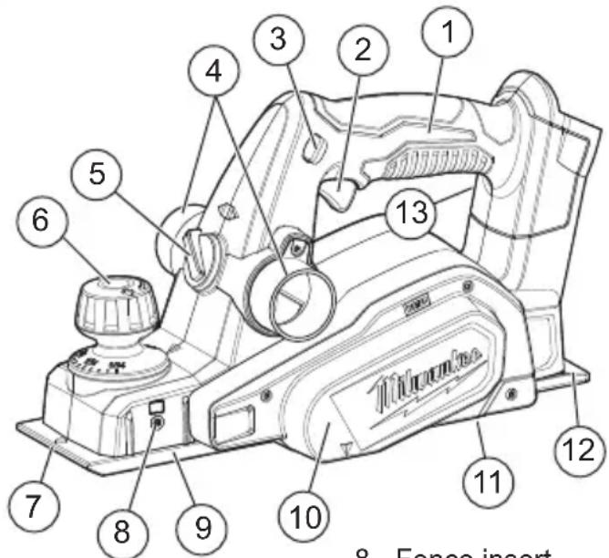
- Handle
- Trigger
- Trigger lock-off
- Exhaust ports
- Exhaust selector
- Depth knob (grasping surface)
-
Chamfer groove
-
Fence insert (both sides of tool)
- Front shoe
- Drive belt guard
- Kickstand (not shown)
- Rear shoe
- Wrench storage (not shown)
ASSEMBLY
WARNING
Recharge only with the charger specified for the battery. For spe-ng instructions, read the operator's lied with your charger and battery.
Removing/Inserting the Battery
To remove the battery, push in the release buttons and pull the battery pack away from the tool.
WARNING
Always remove battery pack before changing or removing accessories.
To insert the battery, slide the pack into the body of the tool. Make sure it latches securely into place.
WARNING
Only use accessories specifically recommended for this tool. Others dous.
To reduce the risk of injury, wear safety goggles or glasses with side shields.
Dust from surface coatings such as polyurethanes, linseed oil, etc., can self-ignite. To reduce the risk of fire, empty the dust bag when it becomes about half-full and never store or leave a planer without totally emptying its dust bag. Also follow the recommendations of the coatings manufacturers.
Dust Collection
Switch the exhaust selector to the left or right, depending on your job. Use the accessory dust bag (Cat. No. 42-16-2623) or a connected, running vacuum when using the planer to keep the workplace cleaner. Install the dust bag or a vacuum hose (1-1/2" diam.) by twisting onto the selected exhaust port. Always empty and clean the dust bag thoroughly when it becomes about half-full and upon completion of a job.
WARNING
Blades are sharp and fragile. Handle with care. Laceration and/the blade can occur.
Installing/Replacing Blades
The planer blades have two cutting edges, and may be reversed when one of the cutting edges becomes dull or chipped. Do not sharpen planer blades. Always change/reverse blades in pairs. Use only 3-1/4", tungsten-carbide or carbide, double-edged (reversible) planer blades.
WARNING
Always change/reverse blades in pairs. Unpaired blades can cause vibration, loss of control, and lowerance.
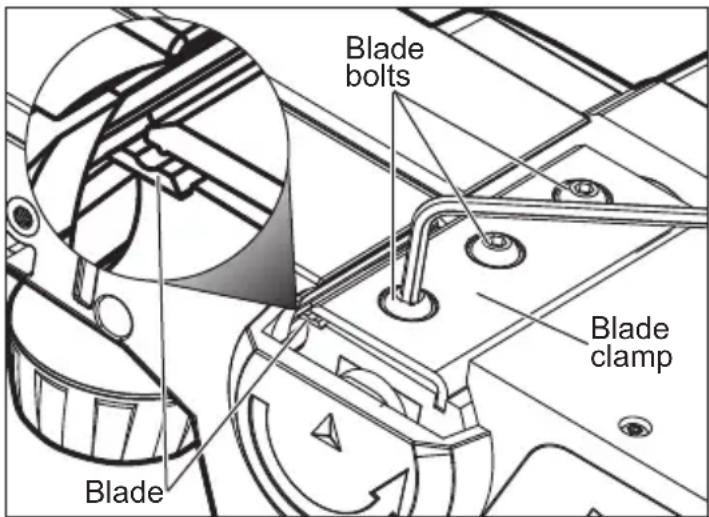
To remove blades:
- Remove battery pack.
- Clean dust and debris from the blade drum.
- Using the 1/8" hex wrench provided, loosen (do not remove) the three blade bolts.
- Using a scrap piece of wood, slide the old blade out of the blade clamp.
NOTE: If the blade is difficult to remove, clean the blade and blade clamp with alcohol, mineral spirits, or lacquer thinner.
- Rotate blade drum and repeat for other blade.
To install blades:
-
Reverse blades or use new blades.
-
Align the grove on the top of the blade with the ridge of the blade clamp and carefully slide the blade onto the drum.
- Center the blade lengthwise - it will overhang the blade clamp slightly on both sides.
- Using a block of wood, push the blade back towards the blade clamp so that the inner side of the blade is pressed against the step on the drum. This will ensure proper alignment and reduce tool vibration.
- Tighten all three blade bolts securely.
- Rotate blade drum and repeat for other blade.
- Once installed, rotate the blade drum to ensure the blade does not contact the shoe or housing, and that the blades are both installed straight.
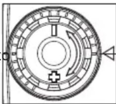
Adjusting the Depth of Cut
- Remove battery pack.
- Determine the amount of material to be removed during each pass of the planer. Take int account the moisture and hardness of the workpiece, as well as the desired feed rate.
- Each detent is 1/256" (0.1 mm). Turn the knob clockwise to increase the depth of cut, counterclockwise to decrease the depth of cut. Do not change the depth of cut while planing.
- Make a test cut. If the planer moves easily through the workpiece, increase the depth of cut. If the planer seems to strain, decrease the depth of cut.
Installing the guide fence
Use the guide fence for additional stability when cutting workpieces up to 3-1/4" wide, and when beveling at up to a 45° angle.
- Remove battery pack
- Screw the guide fence into the left or right fence insert.
- Using the thumb screws, adjust the width and bevel according to the job.
Closing the Kickstand
The kickstand is provided to protect the blade when the tool is set down. It is pushed up automatically during a normal planing operation. To close the kickstand manually, push closed and slide to the side.
natural_image
Pure mechanical diagram of a circular component with internal arrows and cross symbol (no text or labels)
natural_image
Pure mechanical diagram of a circular component with internal arrows and cross symbol (no text or labels)OPERATION
AWARNING Always remove battery pack before changing or removing accessories. Only use accessories specifically recommended for this tool. Others may be hazardous. To reduce the risk of injury, always wear safety goggles or glasses with side shields.
Operation
- Remove battery pack.
- Check blades. Replace if necessary.
- Install guide fence, if desired.
- Turn the exhaust selector to the desired side. Install dust bag or vacuum on appropriate side of tool, if desired.
- Clamp work securely.
- Insert battery pack.
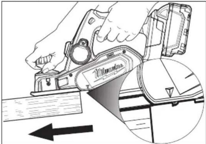
- Securely grasp the tool by the handle and the depth adjustment knob.
- Line up the front of the tool with the workpiece. WITHOUT contacting the drum to the workpiece, press down on the trigger lock-off and pull the trigger. Wait for the tool to come to full speed before beginning to avoid overloading and damaging the tool.
natural_image
Line drawing of a hand using a power tool to cut a component, with an inset showing the blade and arrow (no text or symbols)-
Keeping the front shoe flush with the workpiece, use gentle pressure to guide the planer. All pressure should be on the front shoe when starting the cut. Transfer downward pressure to the rear shoe as it contacts the workpiece.
-
For best results, push planer through the workpiece at an even rate. Do not push too fast as it will strain the motor and could damage the blades. Do not pull the planer backward over the workp
natural_image
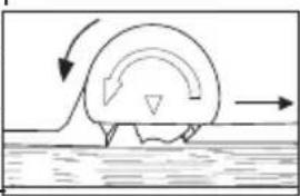
Simple line drawing of a boat creating a wake over water, with no text or symbols present.Slow feed + shallow depth of cut = smooth finish Faster feed + deep depth of cut = rough finish
- When finished with the pass, lift the planer away from the workpiece. Wait for the blade to come to a complete stop before setting down.
- Continue using progressive cuts until near the desired depth. Set the adjustment knob to a very shallow depth for the final passes. This will ensure a smooth finish.
-
Empty and clean the dust bag thoroughly when it becomes about half-full and upon completion of a job.
-
If chute becomes clogged, remove battery pack and clear all dust and debris. WARNING! Keep hands and fingers away from dust chute. Turn off tool and remove battery pack before clearing jams.
Types of Cuts
Rabbeting, Shiplapping
Rabbeting, or shiplapping, is a type of step cut achieved by making repetitive passes. Use the guide fence to ensure a straight cut.
- Align the blade edge with the cutting line and secure the guide fence against the side of the workpiece.
- Keep the edge of the fence against the workpiece as the planer is moved through the workpiece.
- Repeat until the desired depth is reached. Maximum rabbeting depth is 27/64".
natural_image
Technical line drawing of a Pilimber industrial machine with mounting base and control panel (no text or symbols)
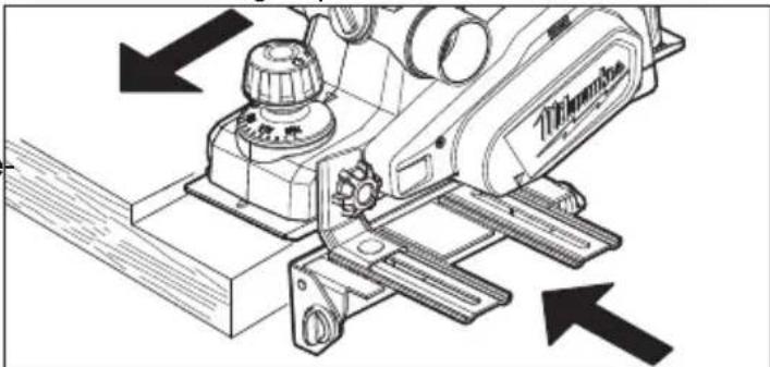
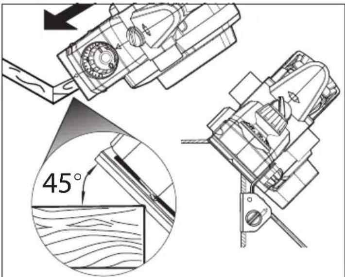
Chamfering
Chamfering is a type of angle cut. Use the guide fence to ensure the same angle is cut during each repetitive pass.
- Align the chamfer groove in the front shoe with the edge of the workpiece at the desired angle.
- Secure the guide fence against the side of the workpiece, using the bevel thumb screws.
- Keep the edge of the fence against the workpiece as the planer is moved through the workpiece.
- Repeat until the desired chamfer is reached.
MAINTENANCE
WARNING
To reduce the risk of injury, always unplug the charger and remove the battery pack from the charger or tool before performing any maintenance. Never disassemble the tool, battery pack or charger. Contact a MILWAUKEE service facility for ALL repairs.
Maintaining Tool
Keep your tool, battery pack and charger in good repair by adopting a regular maintenance program. Inspect your tool for issues such as undue noise, misalignment or binding of moving parts, breakage of parts, or any other condition that may affect the tool operation. Return the tool, battery pack, and charger to a MILWAUKEE service facility for repair. After six months to one year, depending on use, return the tool, battery pack and charger to a MILWAUKEE service facility for inspection.
If the tool does not start or operate at full power with a fully charged battery pack, clean the contacts on the battery pack. If the tool still does not work properly, return the tool, charger and battery pack, to a MILWAUKEE service facility for repairs.
WARNING
To reduce the risk of personal injury and damage, never immerse your tool, battery pack or charger in liquid or allow a liquid to flow inside them.
Cleaning
Clean dust and debris from vents. Keep handles clean, dry and free of oil or grease. Use only mild soap and a damp cloth to clean, since certain cleaning agents and solvents are harmful to plastics and other insulated parts. Some of these include gasoline, turpentine, lacquer thinner, paint thinner, chlorinated cleaning solvents, ammonia and household detergents containing ammonia. Never use flammable or combustible solvents around tools.
Repairs
For repairs, return the tool, battery pack and charger to the nearest service center.
ACCESSORIES
WARNING
Use only recommended accessories. Others may be hazardous.
For a complete listing of accessories, go online to www.milwaukeeetool.com or contact a distributor.
SERVICE - UNITED STATES
1-800-SAWDUST (1.800.729.3878)
Monday-Friday, 7:00 AM - 6:30 PM CST
or visit www.milwaukeetool.com
Contact Corporate After Sales Service Technical Support with technical, service/repair, or warranty questions.
Email: metproductsupport@milwaukeeetool.com
Become a Heavy Duty Club Member at www.milwaukeeetool.com to receive important notifications regarding your tool purchases.
SERVICE - CANADA
Milwaukee Tool (Canada) Ltd 1.800.268.4015
Monday-Friday, 7:00 AM - 4:30 PM CST or visit www.milwaukeeetool.ca
LIMITED WARRANTY USA & CANADA
Every MILWAUKEE power tool* (see exceptions below) is warranted to the original purchaser only to be free from defects in material and workmanship. Subject to certain exceptions, MILWAUKEE will repair or replace any part on an electric power tool which, after examination, is determined by MILWAUKEE to be defective in material or workmanship for a period of five (5) years** after the date of purchase unless otherwise noted. Return of the power tool to a MILWAUKEE factory Service Center location or MILWAUKEE Authorized Service Station, freight prepaid and insured, is required. A copy of the proof of purchase should be included with the return product. This warranty does not apply to damage that MILWAUKEE determines to be from repairs made or attempted by anyone other than MILWAUKEE authorized personnel, misuse, alterations, abuse, normal wear and tear, lack of maintenance, or accidents.
Normal Wear: Many power tools need periodic parts replacement and service to achieve best performance. This warranty does not cover repair when normal use has exhausted the life of a part including, but not limited to, chucks, brushes, cords, saw shoes, blade clamps, o-rings, seals, bumpers, driver blades, pistons, strikers, lifters, and bumper cover washers.
*This warranty does not cover Air Nailers & Staplers; Airless Paint Sprayer; Cordless Battery Packs; Gasoline Driven Portable Power Generators; Hand Tools; Hoist – Electric, Lever & Hand Chain; M12™ Heated Gear; Reconditioned Product; and Test & Measurement Products. There are separate and distinct warranties available for these products.
**The warranty period for Job Site Radios, M12™ Power Port, M18™ Power Source, Jobsite Fan and Trade Titan™ Industrial Work Carts is one (1) year from the date of purchase. The warranty period for the Drain Cleaning Cables and AIRSNAKE™ Drain Cleaning Air Gun Accessories is two (2) years from the date of purchase. The warranty period for the M18™ Compact Heat Gun, 8 Gallon Dust Extractor, M18™ Framing Nailers, M18 FUEL™ 1/2" Ext. Anvil Controlled Torque Impact Wrench w/ ONE-KEY™, and the M18 FUEL™ 1" High Torque Impact Wrench w/ ONE-KEY™ is three (3) years from the date of purchase. The warranty period for the LED in the LED Work Light and the LED Upgrade Bulb for the Work Light is the lifetime of the product subject to the limitations above. If during normal use the LED or LED Bulb fails, the part will be replaced free of charge.
Warranty Registration is not necessary to obtain the applicable warranty on a MILWAUKEE power tool product. The manufacturing date of the product will be used to determine the warranty period if no proof of purchase is provided at the time warranty service is requested. ACCEPTANCE OF THE EXCLUSIVE REPAIR AND REPLACEMENT REMEDIES DESCRIBED HEREIN IS A CONDITION OF THE CONTRACT FOR THE PURCHASE OF EVERY MILWAUKEE PRODUCT. IF YOU DO NOT AGREE TO THIS CONDITION, YOU SHOULD NOT PURCHASE THE PRODUCT. IN NO EVENT SHALL MILWAUKEE BE LIABLE FOR ANY INCIDENTAL, SPECIAL, CONSEQUENTIAL OR PUNITIVE DAMAGES, OR FOR ANY COSTS, ATTORNEY FEES, EXPENSES, LOSSES OR DELAYS ALLEGED TO BE AS A CONSEQUENCE OF ANY DAMAGE TO, FAILURE OF, OR DEFECT IN ANY PRODUCT INCLUDING, BUT NOT LIMITED TO, ANY CLAIMS FOR LOSS OF PROFITS. SOME STATES DO NOT ALLOW THE EXCLUSION OR LIMITATION OF INCIDENTAL OR CONSEQUENTIAL DAMAGES, SO THE ABOVE LIMITATION OR EXCLUSION MAY NOT APPLY TO YOU. THIS WARRANTY IS EXCLUSIVE AND IN LIEU OF ALL OTHER EXPRESS WARRANTIES, WRITTEN OR ORAL. TO THE EXTENT PERMITTED BY LAW, MILWAUKEE DISCLAIMS ANY IMPLIED WARRANTIES, INCLUDING WITHOUT LIMITATION ANY IMPLIED WARRANTY OF MERCHANTABILITY OR FITNESS FOR A PARTICULAR USE OR PURPOSE; TO THE EXTENT SUCH DISCLAIMER IS NOT PERMITTED BY LAW, SUCH IMPLIED WARRANTIES ARE LIMITED TO THE DURATION OF THE APPLICABLE EXPRESS WARRANTY AS DESCRIBED ABOVE. SOME STATES DO NOT ALLOW LIMITATIONS ON HOW LONG AN IMPLIED WARRANTY LASTS, SO THE ABOVE LIMITATION MAY NOT APPLY TO YOU, THIS WARRANTY GIVES YOU SPECIFIC LEGAL RIGHTS, AND YOU MAY ALSO HAVE OTHER RIGHTS WHICH VARY FROM STATE TO STATE.
This warranty applies to product sold in the U.S.A. and Canada only. Please consult the 'Service Center Search' in the Parts & Service section of MILWAUKEE's website www.milwaukeeetool.com or call 1.800.SAWDUST (1.800.729.3878) to locate your nearest service facility for warranty and non-warranty service on a Milwaukee electric power tool.
LIMITED WARRANTY - MEXICO, CENTRAL AMERICA & CARIBBEÁN
TECHTRONIC INDUSTRIES' warranty is for 5 years since the original purchase date.
This warranty card covers any defect in material and workmanship on this Product.
To make this warranty valid, present this warranty card, sealed/stamped by the distributor or store where you purchased the product, to the Authorized Service Center (ASC). Or, if this card has not been sealed/stamped, present the original proof of purchase to the ASC. Call 55 4160-3547 to find the nearest ASC, for service, parts, accessories or components.
Procedure to make this warranty valid
Take the product to the ASC, along with the warranty card sealed/ stamped by the distributor or store where you purchased the product, and any faulty piece or component will be replaced without cost for you. We will cover all freight costs relative with this warranty process.
Exceptions
This warranty is not valid in the following situations
a) When the product is used in a different manner from the end-user guide or instruction manual.
b) When the conditions of use are not normal
c) When the product was modified or repaired by people not authorized by TECHTRONIC INDUSTRIES.
Note: If cord set is damaged, it should be replaced by an Authorized Service Center to avoid electric risks.
SERVICE AND ATTENTION CENTER
Call to 55 4160-3547
IMPORTED AND COMMERCIALIZED BY
TECHTRONIC INDUSTRIES MEXICO, S.A. DE C.V.
Miguel de Cervantes Saavedra No.301 Piso 5, Torre Norte
natural_image
Pure mechanical component diagram with no text, numbers, or symbolsnatural_image
Illustration of a hand using a power tool to cut a mechanical component, with an inset showing the cutting edge (no text or symbols present)natural_image
Diagram of a curved object partially submerged in water with directional arrows indicating flow or movement (no text or symbols)natural_image
Technical line drawing of a mechanical device with directional arrows indicating assembly or movement (no text or symbols present)
Chanfreinage
Milwaukee Tool (Canada) Ltd 1.800.268.4015
Monday-Friday, 7:00 AM - 4:30 PM CST
www.milwaukeetool.ca
GARANTIE LIMITÉE- AUX ÉTATS-UNIS ET AU CANADA
natural_image
Technical diagram of a circular mechanical component with internal components and directional arrows (no text or labels)natural_image
Illustration of a hand using a Pilma tool to cut a mechanical part, with an inset showing the cutting edge (no text or symbols)natural_image
Simple line drawing of a curved object partially submerged in water with directional arrows indicating flow (no text or symbols)natural_image
Technical line drawing of a machine component with directional arrows indicating assembly or movement (no text or symbols present)
Achaflanado
Lunes a Viernes (9am a 6pm)

- ⚠ WARNING Read all safety warnings, instructions, illustrations and specifica-
- WORK AREA SAFETY
- ELECTRICAL SAFETY
- PERSONAL SAFETY
- POWER TOOL USE AND CARE
- BATTERY TOOL USE AND CARE
- SERVICE
- SPECIFIC SAFETY RULES FOR PLANER
- Planer safety warnings:
- SYMBOLOGY
- SPECIFICATIONS
- FUNCTIONAL DESCRIPTION
- ASSEMBLY
- WARNING
- Removing/Inserting the Battery
- Dust Collection
- Installing/Replacing Blades
- To remove blades:
- To install blades:
- Adjusting the Depth of Cut
- Installing the guide fence
- Closing the Kickstand
- OPERATION
- Types of Cuts
- Rabbeting, Shiplapping
- Chamfering
- MAINTENANCE
- Maintaining Tool
- Cleaning
- Repairs
- ACCESSORIES
- SERVICE - UNITED STATES
- 1-800-SAWDUST (1.800.729.3878)
- SERVICE - CANADA
- Milwaukee Tool (Canada) Ltd 1.800.268.4015
- LIMITED WARRANTY USA & CANADA
- LIMITED WARRANTY - MEXICO, CENTRAL AMERICA & CARIBBEÁN
- Procedure to make this warranty valid
- Exceptions
- Chanfreinage
- GARANTIE LIMITÉE- AUX ÉTATS-UNIS ET AU CANADA
- Achaflanado
Brand : MILWAUKEE
Model : M18 2623-21
Category : Plane