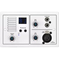
ARM-880WP1 - Audio/video converter Monacor - Free user manual and instructions
Find the device manual for free ARM-880WP1 Monacor in PDF.


User questions about ARM-880WP1 Monacor
0 question about this device. Answer the ones you know or ask your own.
Ask a new question about this device
Download the instructions for your Audio/video converter in PDF format for free! Find your manual ARM-880WP1 - Monacor and take your electronic device back in hand. On this page are published all the documents necessary for the use of your device. ARM-880WP1 by Monacor.
USER MANUAL ARM-880WP1 Monacor
Audiosignal-Matrix-Router Audio Signal Matrix Router
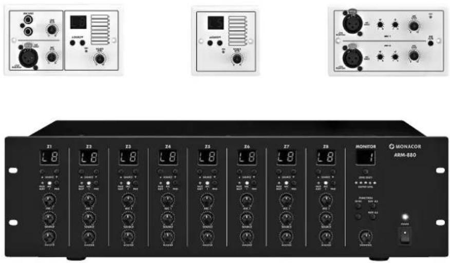
natural_image
Black desktop computer with a microphone and two adjacent devices (no visible text or symbols)ARM-880
LINE: 20 Hz-20 kHz, ±3 dB
MIC:....80 Hz-18 kHz, ±3 dB
MIC 1: .....300mV/660Ω
PAGING MIC 1 + 2: . . .500mV/10kΩ
LINE 1-4:....0,2-2 V/47 kΩ
LINE 5-8: .....350mV
MIC 5-8:....5mV
Please read these instructions carefully prior to operation and keep them for later reference. All operating elements and connections described can be found on the fold-out page 3.
Connection of the matrix router requires adequate technical knowledge in audio technology and is to be made by experts only; in addition, they should also make the basic settings (chapters 4 and 5).
Operation of the matrix router (chapter 6) is easy, even for adults without any expert knowledge. However, in case of any queries, please contact your installer or retailer.
Contents
1 Operating Elements and Connections 10
1.1 Front panel ..... 10
1.2 Rear panel 10
1.3 Accessories....11
1.3.1 ARM-880RC and ARM-880RCE ..... 11
1.3.2 ARM-880WP1 and ARM-880WP2 ..... 11
1.3.3 ARM-880WP3 11
2 Safety Notes 11
3 Applications....12
4 Setting Up and Connecting the Matrix Router 12
4.1 Audio units with line output ..... 12
4.2 Microphones 12
4.3 Alarm inputs ..... 12
4.4 Audio signal for all zones ..... 12
4.5 Wall modules ..... 12
4.6 Power amplifier or active system ..... 12
4.7 Extension of the system to up to 32 zones . 12
4.8 Power supply and emergency power supply 13
5 Basic Settings 13
6 Operation....14
6.1 Matrix router ARM-880 ..... 14
6.1.1 Selecting the signal sources for the zones 14
6.1.2 Announcements via MIC1 ..... 14
6.1.3 Monitoring the zones via the speaker . . 14
6.2 Zone paging microphone ARM-880RC . . 14
6.3 Wall modules ..... 14
6.3.1 ARM-880WP1 and ARM-880WP2 . . . . 14
6.3.2 ARM-880WP3 14
7 Specifications 15
1 Operating Elements and Connections
1.1 Front panel
1 POWER switch
2 Power LED
For each of the eight PA zones separate LEDs and operating elements are available which allow different configuration of the zones:
3 Display to indicate the signal source selected with the buttons SOURCE (9): L1 - L8 = signals of the inputs LINE 1 - 4 (34) and LINE / MIC 5 - 8 (36)
L = signal of the additional input (22) or of the wall module connected (ARM-880WP1, ARM-880WP3)
OF = none of these signals is selected (OFF)
4 LED MIC 1: lights up when a microphone connected to the jack MICROPHONE 1 (40) takes priority over other signal sources (automatic talkover); switchable with the button PRIORITY (10)
5 LED PAGE BUSY: lights up when an announcement is made via the zone paging microphone ARM-880RC connected
6 Mixing control MIC 1 for the level of a microphone connected to the jack MICROPHONE 1 (40)
7 Mixing control SOURCE for the level of the signal source selected with the buttons SOURCE (9)
8 Control MASTER for the overall volume of the zone
9 Buttons SOURCE for selection of the signal source (item 3) After selection, press the button ENTER (14) within 10 seconds to confirm.
10 Button PRIORITY to give priority to a microphone connected to the jack MICROPHONE 1 (40) over other signal sources (automatic talkover); with the priority function activated, the LED MIC 1 (4) lights up
The adjustments for monitoring the PA zones via the integrated speaker are made in the operating panel MONITOR, in addition to other features:
11 Display to indicate the zone selected with the button ZONE SELECT (12)
12 Button ZONE SELECT to select the zone to be monitored After selection, press the button ENTER (14) within 10 seconds to confirm.
13 Level LEDs for the output signal of the selected zone
14 Button ENTER to confirm a selection with the buttons SOURCE (9), ZONE SELECT (12) or BGM ALL (17)
15 Button ESC to interrupt a selection started with the buttons SOURCE (9), ZONE SELECT (12) or BGM ALL (17) (to stop the flashing of the displays and to switch back to the previous adjustment)
16 Volume control MONITOR for the integrated speaker
17 Button BGM ALL to select the same signal source for all zones
After selection, press the button ENTER (14) within 10 seconds to confirm.
18 Button PAGE ALL to give priority to a microphone connected to the jack MICROPHONE 1 (40) over other signal sources for all zones
1.2 Rear panel
For easier handling when connecting, the green screw terminals (19, 22, 29, 30, 36) can be removed from their plug-in connections.
19 Output for the audio signal of the respective PA zone for connection to a power amplifier
20 Tone controls for the respective zone
21 Connection for a wall module (ARM-880WP...)
22 Additional input for an audio signal (line level) which only arrives at the corresponding zone
23 Control GAIN for adapting the zone output level to the input sensitivity of the connected amplifier or to adjust the maximum admissible zone volume
24 Control PAGE to adjust the volume in each zone for the signals of the connected zone paging microphones [jacks PAGING MIC 1 and 2 (38)]
25 Button REMOTE WALL CTRL Button pressed: The signal source for the zone can only be selected via a connected wall module Button not pressed: The signal source can only be selected at the matrix router.
26 Level control for the audio signal of the additional input (22) and for the audio signal of a wall module connected to the jack (21)
27 Mains jack for connection to a socket (230 V/ 50 Hz) via the supplied mains cable The support for the mains fuse is located below the mains jack. Only replace a blown fuse by one of the same type.
28 DIP switches to define the master unit and the slave units when several units ARM-880 are interconnected to obtain additional PA zones ( chapter 4.7)
IMPORTANT! At the master unit or when one ARM-880 only is used in the system, the switch MASTER must be in the lower position ON and all other switches in the upper position. Otherwise the signals of the inputs LINE 1 – 4 (34) and LINE / MIC 5 – 8 (36) are not routed to the zone outputs (19).
29 (Fire) alarm inputs If the contact for one zone is connected to the contact "G", a (fire) alarm signal sounds in the zone and the indication "AL" flashes on the display (3). The alarm volume can be adjusted with the control TONE OUTPUT (31).
30 Terminal strip EMERGENCY Contacts BATT SUPPLY + and – for a 24 V emergency power supply
Contacts COMMON and ALERT connected: the alarm signal is converted into a pulsating signal sound
Contacts COMMON and EVAC connected: the alarm signal is converted into a rising siren signal
Contacts EMC IN and GND for an (emergency) signal taking priority over other signals: As soon as a signal is present at these contacts, it will be routed to all zones. Other signals will be interrupted and the indication "AL" will flash on the displays (3). The signal volume can be adjusted with the control EMC INPUT (32).
31 Control TONE OUTPUT for the volume of the alarm signal
32 Control EMC INPUT for the volume of the signal at the contact EMC IN of the terminal EMERGENCY (30)
33 D-Sub connections (DC-37) to interconnect several units ARM-880 to obtain additional PA zones (max. 32), chapter 4.7
34 Stereo inputs LINE 1 - 4 for connection of audio units with line output (e. g. radio, MP3 / CD player, tape deck)
35 Control GAIN for input level matching of the inputs LINE 1 - 4
36 Audio inputs LINE / MIC 5 - 8 for connection of audio units with line output or for connection of microphones
37 Selector switch for the inputs LINE / MIC 5-8
LINE = for an audio unit with line output MIC = for a microphone
PHANTOM = for a microphone requiring a phantom power (46 V)
38 RJ45 jacks PAGING MIC 1 and 2 for con nection of two zone paging micro-phones ARM-880RC
39 Control GAIN for the sensitivity of the inputs PAGING MIC 1 and 2 (38)
40 Jack MICROPHONE 1 for a microphone The microphone signal can be heard in all zones: to be adjusted with the controls MIC 1 (6)
41 Control GAIN for the sensitivity of the input MICROPHONE 1 (40)
42 Tone controls HF (high frequencies) and LF (low frequencies) for the microphone connected to the jack (40)
1.3 Accessories
The units of the figures 2 to 6 are available as accessories and are not supplied with the matrix router ARM-880.
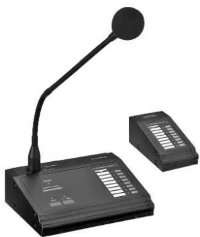
1.3.1 ARM-880RC and ARM-880RCE
Zone paging microphone and extension module
43 Switch CHIME
2-TONE = 2-tone chime when pressing the button TALK (52)
OFF = no chime
4-TONE = 4-tone chime
44 Control CHIME for the chime volume
45 Control MIC for the microphone volume
46 Jack CONNECT TO ARM-880 for connection of the microphone to the jack PAGING MIC 1 or 2 (38)
47 Jack 24V= for connection of the power supply unit provided
48 POWER switch
49 Connection cable for a possible extension module ARM-880RCE (Chapter 4.7)
50 DIP switches to address the extension module
Switch 1 to ON for module 1
Switch 2 to ON for module 2
Switch 3 to ON for module 3
51 Jack MIC to insert the supplied gooseneck microphone
52 Button TALK
53 Button ALL CALL for announcements in all zones
54 Indication for the output level
55 POWER LED
56 Removable label to mark the zones
57 Buttons with indicating LED to activate the zones intended for the announcement
58 Connection plug for the next extension module
1.3.2 ARM-880WP1 and ARM-880WP2
Wall modules for remote control of a zone, ARM-880WP1 in addition to the remote feed-in of audio signals
59 RCA jacks LINE INPUT for feed-in of a line signal which arrives at the corresponding zone only
60 XLR jack MIC INPUT for connection of a microphone* whose signals can only be heard in the corresponding zone
61 Control LINE LEVEL for the volume of an audio unit connected to the jacks LINE INPUT (59)
62 Control MIC LEVEL for the volume of a microphone connected to the jack MIC INPUT (60)
63 Display to indicate the signal source selected with the buttons SOURCE (64) (also see item 3)
64 Buttons SOURCE to select the signal source
65 Power LED ON
66 Control SOURCE LEVEL for the zone volume Adjust the corresponding control MASTER (8) at the ARM-880 to the maximum admissible zone volume.
1.3.3 ARM-880WP3
Wall module for feeding the signals of two microphones to one zone
67 XLR jacks to connect two microphones*
68 Tone controls HF (high frequencies) and LF (low frequencies) for the microphones connected
69 Volume control for the microphones connected
70 Button LINE MUTE: to mute the signal source selected at the ARM-880 so that only the microphone signals of the wall module can be heard
71 Power LED ON
2 Safety Notes
The unit corresponds to all relevant directives of the EU and is therefore marked with €€
WARNING

The unit is supplied with hazardous mains voltage. Leave servicing to skilled personnel only. Inexpert handling or modification of the unit may cause an electric shock hazard.
- The unit is suitable for indoor use only. Protect it against dripping water and splash water, high air humidity and heat (admissible ambient temperature range 0 – 40 °C).
- Do not place any vessels filled with liquid, e. g. drinking glasses, on the unit.
- Do not set the unit into operation, and immediately disconnect the mains plug from the mains socket if
-
there is visible damage to the unit or to the mains cable,
-
a defect might have occurred after a drop or similar accident,
-
malfunctions occur.
The unit must in any case be repaired by skilled personnel.
- Never pull the mains cable to disconnect the mains plug from the mains socket, always seize the plug.
- For cleaning only use a dry, soft cloth, never use chemicals or water.
- No guarantee claims for the unit and no liability for any resulting personal damage or material damage will be accepted if the unit is used for other purposes than originally intended, if it is not correctly connected or operated, or not repaired in an expert way.

If the unit is to be put out of operation definitively, take it to a local recycling plant for a disposal which is not harmful to the environment.
*Caution! Do not connect any microphone with unbalanced output. It may be damaged because a 15 V phantom power is always present at the jacks.
3 Applications
The ARM-880 is an audio signal matrix router which allows to route eight different audio sources (microphones, MP3 / CD player, tuner, PC, etc.) to eight PA zones as desired. By interconnecting four ARM-880 units the system can be extended to 32 zones. A power amplifier for the speakers is required for each zone.
Numerous connections are available for further functions:
- 2 inputs for the zone paging microphones ARM-880RC which allow to make announcements only to certain zones or to all zones
- 1 connection for each zone for a wall module ARM-880WP... for remote control of the zone and /or for feeding an audio signal to the zone
- 1 additional input for each zone for an audio signal routed to the corresponding zone only
- 1 microphone input whose signal can be routed to all zones, with priority function to be activated
- 1 input, e. g. for an emergency signal that is routed to all zones and interrupts other signals
- 1 alarm input for each zone to trigger an alarm signal in the zone
- Connections for a 24 V emergency power supply unit
4 Setting Up and Connecting the Matrix Router
The ARM-880 is designed for insertion into a rack for units with a width of 482 mm (19"), but it can also be used as a table-top unit. For installation into a rack 3 RS (rack spaces) = 133 mm are required.
Prior to connecting units or changing existing connections switch off the matrix router and the units to be connected. All connections should only be made by qualified personnel.
For easier handling when connecting, the green screw terminals (19, 22, 29, 30, 36) can be removed from their plug-in connections.
4.1 Audio units with line output
To be able to route signals of audio units with line output (e. g. radio, MP3 / CD player, tape deck, PC) to the PA zones as desired, use the inputs LINE 1 – 4 (34) and LINE/ MIC 5 – 8 (36). RCA jacks are available for the inputs LINE 1 – 4 and screw terminals for the inputs LINE / MIC 5 – 8. When connecting an audio unit to the screw terminals, set the corresponding switch (37) to position LINE.
For routing the signals of an audio unit exclusively to a certain zone, the additional screw terminal input (22) can also be used which is available for each zone.
The screw terminals are designed for balanced signals. For an unbalanced connection feed the signal to the contact + and connect the contacts - and GND to the signal ground.
4.2 Microphones
When connecting several microphones, these microphones may receive a different priority, i. e. an announcement made via a microphone of high priority may automatically interrupt an announcement made via a microphone of lower priority.
Highest priority is given to the zone paging microphones ARM-880RC which allow to make announcements in certain zones only or in all zones. Two zone paging microphones may be connected to the jacks PAGING MIC 1 and 2 (38). For this purpose, a network cable (e.g. Cat 5 cable) with RJ45 plugs is required. For power supply connect the power supply unit provided to the jack 24 V= (47) and to a mains socket (230V/50Hz).
Medium priority is given to a microphone connected to the jack MICROPHONE 1 (40). The microphone signal can be routed into the zones and volume-adjusted by the controls MIC 1 (6). For priority of this microphone signal over the signals of the inputs LINE 1 – 4 (34) and LINE / MIC 5 – 8 (36), after switching on the matrix router, press the buttons PRIORITY (10) of the corresponding zones. The function can also be activated and deactivated together for all zones with the button PAGE ALL (18).
Note: The priority adjustment is not stored when switching off the matrix router and must be made again, if required, after switching on the matrix router again.
Lowest priority is given to microphones connected to the screw terminals of the inputs LINE/MIC 5–8(36).
The screw terminals are designed for balanced signals. For an unbalanced connection feed the signal to the contact + and connect the contacts - and GND to the signal ground.
If the microphone requires a phantom power (46 V), set the corresponding switch (37) to position PHANTOM. For microphones which do not require any phantom power, set the switch to position MIC.
4.3 Alarm inputs
For each zone, a contact (1 – 8) for alarm triggering is available at the screw terminal FIRE ALARM (29). If this contact is connected to the contact "G" via a corresponding switch, a (fire) alarm signal sounds in the zone and the indication "AL" flashes on the display (3). If the wall module ARM-880WP1 or ARM-880WP2 is connected, "Er" is indicated there. Adjust the alarm volume for all zones with the control TONE OUTPUT (31). The alarm signal has highest priority and interrupts all other signals in the zone.
Instead of the fire alarm signal a pulsating signal sound or a rising siren signal may sound. Connect the contacts ALERT and COMMON of the terminal EMERGENCY (30) for a pulsating signal sound or the contacts EVAC and COMMON for a rising siren signal.
4.4 Audio signal for all zones
If an (emergency) signal with line level is to be routed to all zones, feed the signal to the contacts EMC IN and GND of the terminal EMERGENCY (30). As soon as the signal is present at these contacts, it will be routed to all zones. Other signals will be interrupted and the indication "AL" will flash on the displays (3). The signal volume for all zones can be adjusted with the control EMC INPUT (32).
4.5 Wall modules
Each PA zone can be remote-controlled by connection of the wall module ARM-880WP1 or ARM-880WP2. For remote feed-in of an audio signal into a zone the wall module ARM-880WP1 or ARM-880WP3 can be used.
Connect the RJ45 jack "Net Interface" on the rear side of the module via a network cable (e. g. Cat 5 cable) with RJ45 plugs to the jack REMOTE WALL CTRL (21) of the corresponding zone. The power supply of the wall modules is made via the matrix router. However, for cable lengths exceeding 50 m use a power supply unit (= 24 V, current rating of 500 mA) to be connected to the contacts 24 V- and GND of the screw terminal on the rear side of the module.
Press down the button REMOTE WALL CTRL (25) for zones a wall module is connected to. Otherwise the zone cannot be remote-controlled with the module. For models ARM-880WP1 and ARM-880WP2, "OF" will be indicated on the display (63).
4.6 Power amplifier or active system
A balanced output signal for each zone is present at the screw terminals OUTPUT (19). In each case connect the input of a power amplifier for the speakers to this terminal. If the amplifier is provided with an unbalanced input only, connect it to the contacts + (signal) and GND (ground) only. Alternatively, active speaker systems may be connected to the zone outputs.
4.7 Extension of the system to up to 32 zones
If eight PA zones are not sufficient, the system can be extended to 16, 24 or 32 zones by using up to three further matrix routers ARM-880.
Note: Thus, the number of inputs capable of routing is not increased. Only the signals of the inputs LINE 1 – 4 (34) and LINE / MIC 5 – 8 (36) of the master unit can be routed as desired to all zones available. However, the additional inputs (22) for each zone and the alarm inputs (29) at each ARM-880 can be used. A wall module may be connected to each further zone.
1) Connect the terminal EXTENSION LINK OUT (33) of the master unit (at which all signals to be distributed as desired are present) to the terminal EXTENSION LINK IN of an additional matrix router ARM-880 (= slave unit) via the supplied cable.
2) The DIP switch MASTER (28) at the master unit must be set to the lower position ON. All other DIP switches must be in the upper position.
3) Set the DIP switch SLAVE 1 at the (first) slave unit to the lower position ON. All other DIP switches must be in the upper position.
4) A second slave unit may be connected to the first in the same way and a third to the second slave unit. Set the DIP switch SLAVE 2 at the second slave unit and the DIP switch SLAVE 3 at the third slave unit to the lower position. All other DIP switches must be in the upper position.
5) If the zone paging microphones ARM-880RC are used in the system, these microphones have to be completed with the extension module ARM-880RCE for each slave unit so that also the additional zones can individually be selected. Connect the cable (49) of the zone paging microphone to the jack on the lower side of the extension module. If re quired, connect the plug (58) of the extension module to the next extension module.
Address each extension module with its DIP switches (50):
| Module | For the zones | Set DIP switch No. x to position ON |
| 1 | 9-161 | |
| 2 | 17-242 | |
| 3 | 25-323 |
4.8 Power supply and emergency power supply
Finally connect the supplied mains cable to the mains jack (27) first and then to a socket (230 V/50 Hz).
For continuous operation of the matrix router in case of mains failure, connect a 24 V emergency power supply unit (e. g. PA-24ESP from MONACOR) to the contacts BATT SUPPLY + and - of the screw terminal EMERGENCY (30).
5 Basic Settings
Make the following basic settings at the matrix router for setting it into operation. Do not yet switch on the unit for the time being.
1) The DIP switches (28) must be set as follows:
| Unit | For the zones | Set switch DIP ... to position ON |
| master unit | 1 - 8 | MASTER |
| slave unit 1 | 9-16 | SLAVE 1 |
| slave unit 2 | 17-24 | SLAVE 2 |
| slave unit 3 | 25-32 | SLAVE 3 |
Notes: The switches must be actuated with the unit switched off. When the unit is switched on, there is no change of function. If the master unit is set in the wrong way, the signals of the inputs LINE 1 - 4 (34) and LINE / MIC 5 - 8 (36) cannot be routed to the zone outputs (19).
2) Press down the button REMOTE WALL CTRL (25) of the zones to which a wall module is connected.
3) Set the sliding switches (37) of the inputs LINE / MIC 5 - 8 to the corresponding position:
LINE = for an audio unit with line output
MIC = for a microphone
PHANTOM = for a microphone requiring a phantom power (46 V)
The next steps merely serve as an aid, however, other ways of proceeding are possible as well.
4) Set all controls (20, 23, 24, 26, 31, 32, 35, 39, 41, 42) on the rear side to mid-position, however, turn the controls GAIN of the inputs which are not used to the left stop to position “—”.
5) For the time being, set the controls MIC 1 (6) and SOURCE (7) of each zone to mid-position and the control MASTER (8) to position "0".
6) First switch on the audio sources connected and the matrix router, then the power amplifiers or active speaker systems connected to the zone outputs (19).
7) In each zone select the input of the inputs 1–8 to be heard at highest volume: Press the button SOURCE ▲ or ▼ (9) repeatedly until the display (3) shows the number of the input (L1 ... L8). Then confirm the selection with the button ENTER (14) within 10 seconds. Adjust the desired volume with the control MASTER (8) and with the volume control of the power amplifier or the active speaker system.
Note: Select the signal input of the zones to which the wall module ARM-880WP1 or ARM-880WP2 is connected with the button BGM ALL (17) or directly at the module with the buttons SOURCE (64).
8) The controls GAIN (35) of the inputs LINE 1 - 4 allow to adapt the input sensitivity to the output level of the units connected and to equalize differences in volume occurring when switching over the inputs.
9) The controls GAIN (23) allow to adapt the output level to the input sensitivity of the connected power amplifier or active speaker system for each zone. However, the controls also allow to limit the output level so that an excessive volume cannot be adjusted by mistake with the controls MASTER.
10) Adjust the sound separately for each zone with the controls (20). The control HF is intended for the high frequencies and the control LF for the low frequencies.
11) If a microphone has been connected to the jack MICROPHONE 1 (40), make an announcement via this microphone. Adjust the input sensitivity with the control GAIN (41) and the desired volume for the announcements with the controls MIC 1 (6) separately for each zone. The sound for the announcements can be adjusted with the controls LF and HF (42).
12) If a zone paging microphone ARM-880RC is connected;
a) Set the controls CHIME (44) and MIC (45) at the microphone to mid-position for the time being.
b) Select with the switch CHIME (43) if a chime is to sound prior to an announcement when pressing the button TALK (52), and if so, which type:
2-TONE = 2-tone chime
OFF = no chime
4-TONE = 4-tone chime
c) Press the button ALL CALL (53) so that an announcement can be heard in all zones.
d) Keep the button TALK pressed, possibly wait for a chime and make an announcement via the microphone. Adjust the volume of the announcement separately for each zone with the controls PAGE (24) at the matrix router.
e) If required, change the volume ratio of chime and announcement with the controls CHIME (44) and MIC (45).
f) If two zone paging microphones have been connected, adjust the volume ratio of the microphones with the controls GAIN (39).
g) To mark the zone buttons (57), a label (56) is provided which can be removed and replaced, if required. The same label is also available at the extension modules ARM-880RCE.
13) Feed an audio signal to the wall module ( chapter 6.3) or to the additional input of the zones where the wall module ARM-880WP1 or ARM-880WP3 is connected or the additional audio input (22) is used. In each case select the input with the buttons SOURCE (9, 64) (shown on the display by an "L") and adjust the volume with the control REM. SOURCE ... GAIN (26).
14) If the alarm inputs of the screw terminal FIRE ALARM (29) are used, trigger an alarm for each zone (bridge the contact for one zone and the contact G). Adjust the volume of the alarm signal for all zones of a matrix router with the control TONE OUTPUT (31).
15) When the input EMC IN of the terminal EMERGENCY (30) is used, feed an (emergency) signal to the input and adjust the volume for all zones with the control EMC INPUT (32).
6 Operation
6.1 Matrix router ARM-880
Switch on the unit with the POWER switch (1). The power indication (2) lights up. The zone displays (3) show the selected signal source for each zone. The monitor display (11) shows the zone selected for monitoring via the integrated speaker.
6.1.1 Selecting the signal sources for the zones
For the zones to which the wall module ARM-880WP1 or ARM-880WP2 is connected, the signal source can only directly be selected with the buttons SOURCE (64) at the module. The corresponding buttons SOURCE (9) at the matrix router have no function.
1) Press the button SOURCE ▲ or ▼ (9) repeatedly or keep it pressed to select the signal source. The display (3) shows the source:
$$ \begin{array}{l} \text { L 1 - L 8 } = \text { signals of the inputs LINE 1 - 4 } \ \text {(34) and LINE / MIC 5 - 8 (36)} \end{array} $$
$$ \begin{array}{l} \text { L } = \text { signal of the additional input(22) } \ \text { or of the wall module connected(ARM- } \ \text { 880WP1,ARM - 880WP3) } \end{array} $$
$$ \begin{array}{l} \text { OF } = \text { none of these signals has been } \ \text { selected(OFF) } \end{array} $$
2) After the selection the number on the display flashes for 10 seconds. Press the button ENTER (14) during this time to confirm the selection. Otherwise the previous selection is kept. A procedure of selection can be stopped at any time with the button ESC (15).
3) For selection of the same signal for all zones (even those to which a wall module is connected), this can be made conveniently with the button BGM ALL (17). After selection press the button ENTER.
4) If required, readjust the volume of the selected signal source separately for each zone with the control SOURCE.
5) Adjust the overall volume of the mixed signal of signal source and announcements via MIC 1 (Chapter 6.1.4) separately for each zone with the control MASTER (16).
Hint: When the signals of the inputs 1 - 8 cannot be heard in any zone, check the position of the DIP switches (28) [ chapter 5, step 1].
6.1.2 Announcements via MIC 1
If a microphone has been connected to the jack MICROPHONE 1 (40), announcements for certain zones or for all zones can be made via this microphone.
1) Adjust the volume for the announcements separately in each zone with the control MIC 1 (6). Set the controls of the zones to "0" where the announcements are not to be heard.
2) The microphone signal can be added to the signal source selected for each zone or it can interrupt the signal of the source (automatic talkover). Press the button PRIORITY (10) for the zones where the signal of the source is to be interrupted for an announcement. The LED MIC 1 (4)
lights up. Press the button PAGE ALL (18) to activate the automatic talkover function for all zones.
Note: After switching the matrix router off and on again, the automatic talkover function is deactivated. If required, reactivate the function.
6.1.3 Monitoring the zones via the speaker
To check the zones or to select a signal source for one zone, each of the eight zones can be monitored via the integrated speaker. This speaker exactly reproduces the signals presently heard in the selected zone.
1) Press the button ZONE SELECT (12) repeatedly or keep it pressed to select the zone. The display (11) shows the zone number.
2) After selection, the number flashes on the display for 10 seconds. Press the button ENTER (14) during this time to confirm the selection. Otherwise the previous selection is maintained. A procedure of selection can be stopped at any time with the button ESC (15).
3) Adjust the monitoring volume with the control MONITOR (16). The LED chain OUTPUT LEVEL (13) shows the signal level of the selected zone output (19).
6.2 Zone paging microphone ARM-880RC
1) Switch on the microphone with the POWER switch (48). The POWER indication (55) lights up.
2) First select the PA zones in which the announcement is to be heard with the buttons SPEAKER ZONES (57), if necessary use the buttons of the extension modules ARM-880RCE. To select all zones, press the button ALL CALL (53). The selected zones are in each case indicated by an LED showing blue and can also be deselected with the corresponding button or the button ALL CALL.
If an announcement is made from a second zone paging microphone, the LEDs of the zones where the announcement can be heard show orange. Then these zones cannot be selected.
3) Keep the button TALK (52) pressed for an announcement, possibly wait for the chime, and then speak. If the LED of the button TALK flashes, no zone has been selected.
4) The microphone signal is shown by the LED chain OUTPUT LEVEL (54). The red LED should only shortly light up. If it lights up for a longer time, speak at a lower volume, increase the distance to the microphone or turn the control MIC (45) counter-clockwise accordingly.
If the volume of the announcement is too low, turn the control clockwise accordingly, speak at a higher volume or move closer to the microphone.
Note: The announcements from a zone paging microphone take priority over other signal sources and interrupt their signals in the selected zones. Only alarm signals take an even higher priority ( chapter 4.3).
6.3 Wall modules
6.3.1 ARM-880WP1 and ARM-880WP2
As soon as the matrix router is switched on, the power LED (65) of the module lights up and the display (63) shows the selected signal source:
L 1-L 8 = signals of the inputs LINE 1 - 4 (34) and LINE / MIC 5 - 8 (36)
L = signal of the additional input (22) or wall module (step 3)
OF = none of these signals is selected (OFF)
1) To switch on another signal source, press the button SOURCE ▲ or ▼ (64) repeatedly or keep it pressed.
2) Adjust the desired volume with the control SOURCE LEVEL (66). If the volume cannot be adjusted to a sufficiently higher volume, turn up the corresponding control SOURCE (7) and/or MASTER (8) at the matrix router accordingly.
3) A microphone* may be connected to the jack MIC INPUT (60) of the module ARM-880WP1 and a unit with line output to the RCA jacks LINE INPUT (59) to be able to hear their signals in the corresponding zone.
a) Use the button SOURCE ▲ or ▼ to switch the display indication to "L". Thus, the jacks LINE INPUT and MIC INPUT are selected.
b) Set the control SOURCE LEVEL to mid-position approximately and turn up the control LINE LEVEL (61) for the connected audio unit and/or the control MIC LEVEL (62) for the microphone so that the signals can be heard well. If an input is not connected, set the corresponding control to "0".
c) Adjust the definitive volume with the control SOURCE LEVEL.
6.3.2 ARM-880WP3
As soon as the matrix router is switched on, the power indication (71) at the module lights up.
1) Connect two microphones* to the jacks MIC INPUT (67) to be able to hear their signals in the corresponding zone.
2) Adjust the volume for the microphones with the controls MIC LEVEL (69). When a microphone input has not been connected, set the corresponding control to "0".
3) When a signal source has been selected at the matrix router for the corresponding zone, the microphone signals can be added to the signal source. The signal source can also be muted with the button LINE MUTE (70) so that only the microphone signals can be heard.
4) The sound can be adjusted separately for each microphone with the controls (68). The controls HF are intended for the high frequencies and the controls LF for the low frequencies.
* It is also possible to use microphones requiring a 15 V phantom power. However, no microphone with unbalanced connection must be used; it may be damaged by the present phantom power.
7 Specifications
ARM-880
Frequency range
LINE: 20 Hz-20 kHz, ±3 dB
MIC:....80 Hz-18 kHz, ±3 dB
Input sensitivity/
input impedance
MIC 1: .....300mV/660Ω
PAGING MIC 1 + 2: . . .500mV/10kΩ
LINE 1-4:....0.2-2 V/47 kΩ
LINE 5-8:....350mV
MIC 5-8:....5mV
Zone inputs (22): . . . .0.3–1.1 V/10 kΩ
EMC IN:....775mV/10kΩ
Phantom power: .....46V for MIC 5–8, to be switched individually
Tone control
Bass range: ....±10dB/100Hz
High range: ....±10dB/10kHz
Crosstalk: ....> 50 dB
THD: ....< 0.07 %
S/N ratio
MIC: ....>65 dB
LINE: > 85 dB
Zone outputs
Rated level: .....1.5V
Impedance: .....600Ω
Power supply
Mains operation: ....230V/50Hz
Power consumption: .30 VA max.
Emergency supply: . . . = 24V
Current consumption: 0.7 A
w/o wall modules
and zone paging
microphones
Ambient temperature: .0–40°C
Dimensions: 482×142×325mm , 3 RS
Weight: 6 kg
ARM-880RC
Phantom power for the
gooseneck microphone: 12 V
Chime: ....switchable 2-tone, 4-tone, off
LED indications: .....operation, output level, selected zones, Talk, All Call
Power supply: .....= 24 V, 65 mA via PSU provided, connected to 230 V/50 Hz
Ambient temperature: .0–40°C
Dimensions
w/o microphone: .....180 × 61 × 143 mm
Weight: 1.25 kg
ARM-880RCE
LED indications: .....selected zones
Power supply:....=24V, 10mA
via ARM-880RC
Ambient temperature: .0–40°C
Dimensions: 180 × 61 × 70 mm
Weight: 525g
ARM-880WP1
Input sensitivity
MIC: 10mV
LINE:....335mV
Phantom power: .....15 V for MIC INPUT
Output level: .....775 mV
THD: .... < 1 %
S/N ratio: ....> 65 dB
LED indications: .....selected signal
source, operation
Power supply: ..... = 24 V, 450 mA via
ARM-880 or for a cable length exceeding 50 m via PSU required additionally
Max. length of the
connection cable: .....1000 m
Ambient temperature: .0–40°C
Dimensions: 146 × 86 × 33 mm
Weight: 155g
ARM-880WP2
LED indications: .....selected signal
source, operation
Power supply: ..... = 24 V, 330 mA via
ARM-880 or for a cable length exceeding 50 m via PSU required additionally
Max. length of the
connection cable: .....1000 m
Ambient temperature: .0–40°C
Dimensions: 86 × 86 × 33 mm
Weight: 75g
ARM-880WP3
Input sensitivity: .....10 mV
Phantom power: .....15V
Output level: 775 mV
THD: ....< 1 %
S/N ratio: ....> 70 dB
LED indications: .....operation
Power supply: ..... = 24 V, 230 mA via
ARM-880 or for a cable length exceeding 50 m via PSU required additionally
Max. length of the
connection cable: .....1000 m
Ambient temperature: .0–40°C
Dimensions: 146 × 86 × 33 mm
Weight: 160g
Subject to technical modification.
LINE : .....20 Hz-20 kHz, ±3 dB
MIC : .....80 Hz-18 kHz, ±3 dB
Gong : .....commutable 2 sons, 4 sons, off
branchement:.....1000m
LINE: 20 Hz-20 kHz, ±3 dB
MIC:....80 Hz-18 kHz, ±3 dB
MIC 1: .....300mV/660Ω
PAGING MIC 1 + 2: . . .500mV/10kΩ
LINE 1-4:....0,2-2 V/47 kΩ
LINE 5-8: .....350mV
MIC 5-8:....5mV
Ingressi per zone (22): 0,3–1,1 V/10 kΩ
EMC IN:....775mV/10kΩ
Alimentazione
LÍNE: 20 Hz-20 kHz, ±3 dB
MIC:....80 Hz-18 kHz, ±3 dB
MIC 1: .....300mV/660Ω
PAGING MIC 1 + 2: . . .500mV/10kΩ
LINE 1-4:....0,2-2V/47kΩ
LINE 5-8:....350mV
MIC 5-8:....5mV
Entradas de zona (22): 0,3–1,1 V/10 kΩ
EMC IN: 775 mV/10 kΩ
Crosstalk: ....> 50 dB
THD: ....< 0,07 %
LINE: 20 Hz-20 kHz, ±3 dB
MIC:....80 Hz-18 kHz, ±3 dB
MIC 1: .....300mV/660Ω
PAGING MIC 1 + 2: . . .500mV/10kΩ
LINE 1-4:....0,2-2 V/47 kΩ
LINE 5-8:....350mV
MIC 5-8:....5mV