
GKS 7000 Professional - Saw BOSCH - Free user manual and instructions
Find the device manual for free GKS 7000 Professional BOSCH in PDF.

| Product type | Handheld circular saw |
| Brand | Bosch |
| Model | GKS 7000 Professional |
| Rated power input | 950 - 1100 W (depending on version) |
| No-load speed | 5200 min⁻¹ |
| Max. blade diameter | 190 mm |
| Min. blade diameter | 184 mm |
| Max. cutting depth at 0° | 65 mm (with 184 mm blade) / 68 mm (with 190 mm blade) |
| Max. cutting depth at 45° | 50 mm (with 184 mm blade) / 52 mm (with 190 mm blade) |
| Base plate dimensions | 271 x 152 mm |
| Weight (according to EPTA 01:2014) | 3.6 kg |
| Protection class | ☐/II (double insulation) |
| Rated voltage | 230 V |
| Blade bore | 19 mm or 20 mm (depending on version) |
| Safety guard | Pendulum guard |
| Spindle lock | Yes |
| Chip ejection | With dust extraction adapter (diameter 35 mm) |
| Parallel guide | Yes, adjustable |
| Bevel cut | Up to 45° |
| Additional handle | Yes, removable |
| Maintenance and cleaning | Clean the ventilation slots, guard, and blade regularly. Use compressed air or a brush. |
| Safety | Safety switch, protective guard, double insulation, quick stop |
| Spare parts and repairability | Bosch after-sales service: www.bosch-pt.com. Repairs by authorized center. |
| General information | Compliant with EU regulations. Do not use for ferrous metals. |
Frequently Asked Questions - GKS 7000 Professional BOSCH
User questions about GKS 7000 Professional BOSCH
0 question about this device. Answer the ones you know or ask your own.
Ask a new question about this device
Download the instructions for your Saw in PDF format for free! Find your manual GKS 7000 Professional - BOSCH and take your electronic device back in hand. On this page are published all the documents necessary for the use of your device. GKS 7000 Professional by BOSCH.
USER MANUAL GKS 7000 Professional BOSCH
natural_image
Technical illustration of a Bosch circular saw cutting into a workpiece (no text or symbols visible)
GKS 7000 Professional

BOSCH
en Original instructions
fr Notice originale
pt Manual original
zh 正本使用说明书
tw 原始使用说明書
ko시용 설명서 원본
English ...... page 6
Français ...... Page 14
natural_image
Close-up of a hand using a Bosch cutting tool on a workbench, with a ruler and labeled component (no text or symbols beyond labels)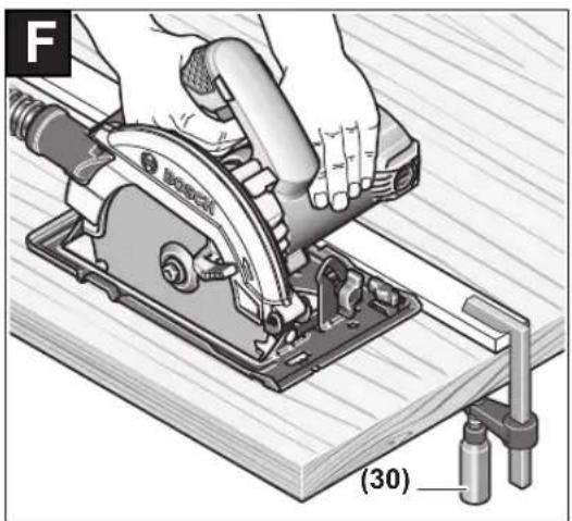
natural_image
Illustration of a hand using a Bosch cutting tool on a wooden workbench, with no visible text or symbols.Bosch Power Tools 1 609 92A 4BN | (19.09.2018)
English
Safety instructions
General Power Tool Safety Warnings
WARNING
Read all safety warnings, instructions, illustrations and specifica-
tions provided with this power tool. Failure to follow all instructions listed below may result in electric shock, fire and/or serious injury.
Save all warnings and instructions for future reference. The term "power tool" in the warnings refers to your mains-operated (corded) power tool or battery-operated (cordless) power tool.
Work area safety
▶ Keep work area clean and well lit. Cluttered or dark areas invite accidents.
▶ Do not operate power tools in explosive atmospheres, such as in the presence of flammable liquids, gases or dust. Power tools create sparks which may ignite the dust or fumes.
▶ Keep children and bystanders away while operating a power tool. Distractions can cause you to lose control.
Electrical safety
▶ Power tool plugs must match the outlet. Never modify the plug in any way. Do not use any adapter plugs with earthed (grounded) power tools. Unmodified plugs and matching outlets will reduce risk of electric shock.
▶ Avoid body contact with earthed or grounded surfaces, such as pipes, radiators, ranges and refrigerators. There is an increased risk of electric shock if your body is earthed or grounded.
▶ Do not expose power tools to rain or wet conditions. Water entering a power tool will increase the risk of electric shock.
▶ Do not abuse the cord. Never use the cord for carrying, pulling or unplugging the power tool. Keep cord away from heat, oil, sharp edges or moving parts.
Damaged or entangled cords increase the risk of electric shock.
▶ When operating a power tool outdoors, use an extension cord suitable for outdoor use. Use of a cord suitable for outdoor use reduces the risk of electric shock.
▶ If operating a power tool in a damp location is unavoidable, use a residual current device (RCD) protected supply. Use of an RCD reduces the risk of electric shock.
Personal safety
▶ Stay alert, watch what you are doing and use common sense when operating a power tool. Do not use a power tool while you are tired or under the influence of drugs, alcohol or medication. A moment of inatten-
tion while operating power tools may result in serious personal injury.
▶ Use personal protective equipment. Always wear eye protection. Protective equipment such as a dust mask, non-skid safety shoes, hard hat or hearing protection used for appropriate conditions will reduce personal injuries.
▶ Prevent unintentional starting. Ensure the switch is in the off-position before connecting to power source and/or battery pack, picking up or carrying the tool. Carrying power tools with your finger on the switch or energising power tools that have the switch on invites accidents.
Remove any adjusting key or wrench before turning the power tool on. A wrench or a key left attached to a rotating part of the power tool may result in personal injury.
▶ Do not overreach. Keep proper footing and balance at all times. This enables better control of the power tool in unexpected situations.
▶ Dress properly. Do not wear loose clothing or jewellery. Keep your hair and clothing away from moving parts. Loose clothes, jewellery or long hair can be caught in moving parts.
▶ If devices are provided for the connection of dust extraction and collection facilities, ensure these are connected and properly used. Use of dust collection can reduce dust-related hazards.
▶ Do not let familiarity gained from frequent use of tools allow you to become complacent and ignore tool safety principles. A careless action can cause severe injury within a fraction of a second.
Power tool use and care
▶ Do not force the power tool. Use the correct power tool for your application. The correct power tool will do the job better and safer at the rate for which it was designed.
▶ Do not use the power tool if the switch does not turn it on and off. Any power tool that cannot be controlled with the switch is dangerous and must be repaired.
▶ Disconnect the plug from the power source and/or remove the battery pack, if detachable, from the power tool before making any adjustments, changing accessories, or storing power tools. Such preventive safety measures reduce the risk of starting the power tool accidentally.
▶ Store idle power tools out of the reach of children and do not allow persons unfamiliar with the power tool or these instructions to operate the power tool. Power tools are dangerous in the hands of untrained users.
- Maintain power tools and accessories. Check for misalignment or binding of moving parts, breakage of parts and any other condition that may affect the power tool's operation. If damaged, have the power tool repaired before use. Many accidents are caused by poorly maintained power tools.
▶ Keep cutting tools sharp and clean. Properly maintained cutting tools with sharp cutting edges are less likely to bind and are easier to control.
▶ Use the power tool, accessories and tool bits etc. in accordance with these instructions, taking into account the working conditions and the work to be performed. Use of the power tool for operations different from those intended could result in a hazardous situation.
▶ Keep handles and grasping surfaces dry, clean and free from oil and grease. Slippery handles and grasping surfaces do not allow for safe handling and control of the tool in unexpected situations.
Service
▶ Have your power tool serviced by a qualified repair person using only identical replacement parts. This will ensure that the safety of the power tool is maintained.
Safety instructions for circular saws
Cutting procedures
▶ HANGER: Keep hands away from cutting area and the blade. Keep your second hand on auxiliary handle, or motor housing. If both hands are holding the saw, they cannot be cut by the blade.
▶ Do not reach underneath the workpiece. The guard cannot protect you from the blade below the workpiece.
▶ Adjust the cutting depth to the thickness of the workpiece. Less than a full tooth of the blade teeth should be visible below the workpiece.
▶ Never hold the workpiece in your hands or across your leg while cutting. Secure the workpiece to a stable platform. It is important to support the work properly to minimise body exposure, blade binding, or loss of control.
▶ Hold the power tool by insulated gripping surfaces, when performing an operation where the cutting tool may contact hidden wiring or its own cord. Contact with a "live" wire will also make exposed metal parts of the power tool "live" and could give the operator an electric shock.
When ripping always use a rip fence or straight edge guide. This improves the accuracy of cut and reduces the chance of blade binding.
▶ Always use blades with correct size and shape (diamond versus round) of arbour holes. Blades that do not match the mounting hardware of the saw will run off-centre, causing loss of control.
▶ Never use damaged or incorrect blade washers or bolt. The blade washers and bolt were specially designed for your saw, for optimum performance and safety of operation.
Kickback causes and related warnings
- kickback is a sudden reaction to a pinched, jammed or mis-aligned saw blade, causing an uncontrolled saw to lift up and out of the workpiece toward the operator;
- when the blade is pinched or jammed tightly by the kerf closing down, the blade stalls and the motor reaction drives the unit rapidly back toward the operator;
- if the blade becomes twisted or misaligned in the cut, the teeth at the back edge of the blade can dig into the top surface of the wood causing the blade to climb out of the kerf and jump back toward the operator.
Kickback is the result of saw misuse and/or incorrect operating procedures or conditions and can be avoided by taking proper precautions as given below.
Maintain a firm grip with both hands on the saw and position your arms to resist kickback forces. Position your body to either side of the blade, but not in line with the blade. Kickback could cause the saw to jump backwards, but kickback forces can be controlled by the operator, if proper precautions are taken.
When blade is binding, or when interrupting a cut for any reason, release the trigger and hold the saw motionless in the material until the blade comes to a complete stop. Never attempt to remove the saw from the work or pull the saw backward while the blade is in motion or kickback may occur. Investigate and take corrective actions to eliminate the cause of blade binding.
When restarting a saw in the workpiece, centre the saw blade in the kerf so that the saw teeth are not engaged into the material. If a saw blade binds, it may walk up or kickback from the workpiece as the saw is restarted.
▶ Support large panels to minimise the risk of blade pinching and kickback. Large panels tend to sag under their own weight. Supports must be placed under the panel on both sides, near the line of cut and near the edge of the panel.
▶ Do not use dull or damaged blades. Unsharpened or improperly set blades produce narrow kerf causing excessive friction, blade binding and kickback.
▶ Blade depth and bevel adjusting locking levers must be tight and secure before making the cut. If blade adjustment shifts while cutting, it may cause binding and kickback.
▶ Use extra caution when sawing into existing walls or other blind areas. The protruding blade may cut objects that can cause kickback.
Lower guard function
▶ Check the lower guard for proper closing before each use. Do not operate the saw if the lower guard does not move freely and close instantly. Never clamp or tie the lower guard into the open position. If the saw is accidentally dropped, the lower guard may be bent. Raise the lower guard with the retracting handle and make sure it moves freely and does not touch the blade or any other part, in all angles and depths of cut.
▶ Check the operation of the lower guard spring. If the guard and the spring are not operating properly, they must be serviced before use. Lower guard may operate
8 | English
sluggishly due to damaged parts, gummy deposits, or a build-up of debris.
The lower guard may be retracted manually only for special cuts such as "plunge cuts" and "compound cuts". Raise the lower guard by the retracting handle and as soon as the blade enters the material, the lower guard must be released. For all other sawing, the lower guard should operate automatically.
▶ Always observe that the lower guard is covering the blade before placing the saw down on bench or floor. An unprotected, coasting blade will cause the saw to walk backwards, cutting whatever is in its path. Be aware of the time it takes for the blade to stop after switch is released.
Additional safety warnings
▶ Do not allow the chip ejector to come into contact with your hands. You may be injured by rotating parts.
▶ Do not use the saw above the level of your head. Doing so will mean you have inadequate control of the power tool.
▶ Use suitable detectors to determine if utility lines are hidden in the work area or call the local utility company for assistance. Contact with electric lines can lead to fire and electric shock. Damaging a gas line can lead to explosion. Penetrating a water line causes property damage or may cause an electric shock.
▶ Do not operate the power tool when stationary. It is not suitable for operation with a saw table.
When performing plunge cuts which are not right-angled, secure the guide plate of the saw so that it will not shift sideways. In the event of a sideways shift, the saw blade may become jammed, which could lead to kick-back.
▶ Do not use HSS saw blades. Such saw blades can easily break.
▶ Do not saw any ferrous metals. Hot chips may ignite the dust extractor.
Products sold in GB only:
Your product is fitted with an BS 1363/A approved electric plug with internal fuse (ASTA approved to BS 1362).
If the plug is not suitable for your socket outlets, it should be cut off and an appropriate plug fitted in its place by an authorised customer service agent. The replacement plug should have the same fuse rating as the original plug.
The severed plug must be disposed of to avoid a possible shock hazard and should never be inserted into a mains socket elsewhere.
▶ Always wait until the power tool has come to a complete stop before placing it down. The application tool can jam and cause you to lose control of the power tool.
▶ Hold the power tool firmly with both hands and make sure you have a stable footing. The power tool can be more securely guided with both hands.
Product Description and Specifications

Read all the safety and general instructions. Failure to observe the safety and general instructions may result in electric shock, fire and/or serious injury.
Please observe the illustrations at the beginning of this operating manual.
Intended use
The power tool is intended for making straight cuts in wood with and against the grain and mitre cuts in wood while resting firmly against the workpiece.
The power tool must not be used to cut ferrous metals.
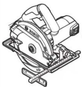
Product features
The numbering of the product features refers to the diagram of the power tool on the graphics page.
(1) On/off switch
(2) Lock-off switch for on/off switch (3 601 F76 04./3 601 F76 0B.)
(2) Lock-on button for on/off switch (3 601 F76 0F./3 601 F76 0K./3 601 F76 0L.)
(3) Spindle lock button
(4) Scale for mitre angles
(5) Wing bolt for mitre angle preselection
(6) Wing bolt for parallel guide
(7) Cut mark 45°
(8) Cut mark 0°
(9) Parallel guide
(10) Retracting blade guard
(11) Base plate
(12) Adjusting lever for retracting blade guard
(13) Chip ejector
(14) Protective guard
(15) Handle (insulated gripping surface)
(16) Motor housing (insulated gripping surface)
(17) Hex key (18) Clamping bolt with washer
(19) Clamping flange
(20) Circular saw blade ^4
(21) Mounting flange
(22) Saw spindle (23) Auxiliary handle (insulated gripping surface) ^A)
(24) Auxiliary handle holder ^A)
(25) Locking screw for auxiliary handle holder ^A
(26) Dust extraction adapter ^4
(27) Fastening screw for dust extraction adapter ^A)
(28) Clamping lever for cutting depth preselection
(29) Cutting depth scale
(30) Pair of screw clamps ^B)
A) Accessories shown or described are not included with the product as standard. You can find the complete selection of accessories in our accessories range.
B) Commercially available (not included in the scope of delivery)
Technical data
| Hand-held circular saw GKS 7000 GKS 7000 GKS 7000 | ||||
| Article number | 3 601 F76 0K1 | 3 601 F76 04. | 3 601 F76 0B0 | |
| 3 601 F76 0B. | ||||
| 3 601 F76 0F. | ||||
| 3 601 F76 0K. | ||||
| 3 601 F76 0L. | ||||
| Rated power input W 950 1100 1100 | ||||
| No-load speed rpm 5200 5200 5200 | ||||
| Max. cutting depth with 184 mm saw blade diameter | ||||
| - at a 0° mitre angle mm 65 65 65 | ||||
| - at a 45° mitre angle mm 50 50 50 | ||||
| Spindle lock ●●● | ||||
| Max. cutting depth with 190 mm saw blade diameter | ||||
| - at a 0° mitre angle mm 68 68 68 | ||||
| - at a 45° mitre angle mm 52 52 52 | ||||
| Base plate dimensions mm 271 x 152 271 x 152 271 x 152 | ||||
| Max. saw blade diameter mm 190 190 190 | ||||
| Min. saw blade diameter | mm 184 184 184 | |||
| Max. base blade thickness | mm | 2.0 | 2.0 | 2.0 |
| Locating bore | mm 20 20 19 | |||
| Weight according to EPTA-Procedure 01:2014 | kg | 3.6 | 3.6 | 3.6 |
| Protection class | ☐/II | ☐/II | ☐/II | |
The specifications apply to a rated voltage [U] of 230 V. These specifications may vary at different voltages and in country-specific models.
Fitting
▶ Only use saw blades the maximum permitted speed of which is higher than the no-load speed of the power tool.
Inserting/changing the circular saw blade
▶ Pull the plug out of the socket before carrying out any work on the power tool.
▶ Wear protective gloves when fitting the saw blade. Danger of injury when touching the saw blade.
▶ Only use saw blades that match the specifications given in this operating manual and on the power tool.
The permitted speed of the application tool must be at least equal to the maximum speed marked on the power tool. If accessories run faster than their rated speed, they may break and fly off.
▶ Do not use abrasive wheels as the application tool under any circumstances.
Selecting the saw blade
You will find an overview of recommended saw blades at the end of these operating instructions.
Removing the saw blade (see figure A)
To change tools, we recommend that you place the power tool down on the front side of the motor housing.
- Press and hold the spindle lock button (3).
▶ Do not press the spindle lock button (3) while the saw spindle is moving. The power tool may become damaged if this happens. - Use the hex key (17) to undo the clamping bolt (18) in rotational direction ①.
- Swing the retracting blade guard (10) back and hold on to it firmly.
10 | English
- Remove the clamping flange (19) and the saw blade (20) from the saw spindle (22).
Fitting the saw blade (see figure A)
To change tools, we recommend that you place the power tool down on the front side of the motor housing.
- Clean the saw blade (20) and all the clamping elements to be fitted.
- Swing the retracting blade guard (10) back and hold on to it firmly.
- Place the saw blade (20) on the mounting flange (21). The cutting direction of the teeth (direction of the arrow on the saw blade) must match the rotational direction of the arrow on the protective guard (10).
- Attach the clamping flange (19) and screw in the clamping bolt in rotational direction ②. Ensure that the mounting flange (21) and clamping flange (19) are installed in the correct position.
- Press and hold the spindle lock button (3).
- Use the hex key (17) to tighten the clamping bolt in rotational direction ②. The tightening torque should be 6–9 Nm, which corresponds to hand-tight plus ¼ turn.
Fitting the auxiliary handle (see figure B)
Fasten the auxiliary handle holder (24) to the protective guard (14) using the locking screw (25).
Secure the auxiliary handle (23) to the auxiliary handle holder (24) using screws.
Dust/chip extraction
The dust from materials such as lead paint, some types of wood, minerals and metal can be harmful to human health. Touching or breathing in this dust can trigger allergic reactions and/or cause respiratory illnesses in the user or in people in the near vicinity.
Certain dusts, such as oak or beech dust, are classified as carcinogenic, especially in conjunction with wood treatment additives (chromate, wood preservative). Materials containing asbestos may only be machined by specialists.
- Use a dust extraction system that is suitable for the material wherever possible.
- Provide good ventilation at the workplace.
- It is advisable to wear a P2 filter class breathing mask.
The regulations on the material being machined that apply in the country of use must be observed.
▶ Avoid dust accumulation at the workplace. Dust can easily ignite.
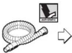
Fitting the dust extraction adapter (see figure C)
Push the dust extraction adapter (26) onto the chip ejector (13) until it clicks into place. Then secure the dust extraction adapter (26) in place with the screw (27).
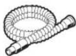
A dust extraction hose with a diameter of 35 mm can be connected to the dust extraction adapter (26).
The dust extraction adapter must only be fitted if an external dust extraction system is connected. Otherwise the extraction duct can become clogged.
▶ No dust bags should be connected to the dust extraction adapter. Otherwise the extraction system can become clogged.
To ensure optimum extraction, the dust extraction adapter (26) must be cleaned regularly.
External dust extraction
Connect the dust extraction hose to a dust extractor (accessory). You will find an overview of connecting to various dust extractors at the end of these operating instructions.
The power tool can be directly connected to the socket of a Bosch all-purpose dust extractor with remote starter. This dust extractor is started up automatically when the power tool is switched on.
The dust extractor must be suitable for the material being worked.
When extracting dry dust that is especially detrimental to health or carcinogenic, use a special dust extractor.
Operation
Operating modes
▶ Pull the plug out of the socket before carrying out any work on the power tool.
Setting the cutting depth (see figure D)
Adapt the cutting depth to the thickness of the workpiece. A space of less than the height of one full tooth should be visible under the workpiece.
Loosen the clamping lever (28). For a smaller cutting depth, pull the saw away from the base plate (11); for a larger cutting depth, push the saw towards the base plate (11). Adjust the desired cutting depth at the cutting-depth scale. Retighten the clamping lever (28).
If you are unable to fully adjust the cutting depth after loosening the clamping lever (28), pull the clamping lever (28) away from the saw and swivel it downwards. Loosen the clamping lever (28) again. Repeat this process until the required cutting depth can be set.
If you are unable to adequately fix the cutting depth after tightening the clamping lever (28), pull the clamping lever (28) away from the saw and swivel it upwards. Loosen the clamping lever (28) again. Repeat this process until the cutting depth is fixed.
Adjusting the mitre angle
Loosen the wing bolt (5). Swivel the saw to the side. Set the required mitre angle on the scale (4). Retighten the wing bolt (5).
Note: When making mitre cuts, the cutting depth is less than the value shown on the cutting depth scale (29).
Cut marks
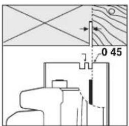
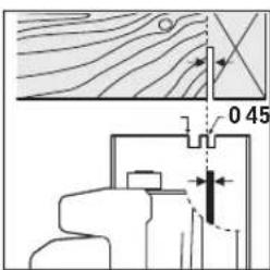
The 0^ cut mark (8) indicates the position of the saw blade when making a right-angled cut. The 45^ cut mark (7) indicates the position of the saw blade when making a 45^ cut.
For a precise cut, place the circular saw against the workpiece as shown in the figure. We recommend making a test cut.
Start-up
Pay attention to the mains voltage. The voltage of the power source must match the voltage specified on the rating plate of the power tool. Power tools marked with 230 V can also be operated with 220 V.
▶ Products that are only sold in AUS and NZ: Use a residual current device (RCD) with a nominal residual current of 30 mA or less.
Switching on/off
(3 601 F76 04./3 601 F76 0B.)
To start the power tool, first press the lock-off switch (2), then press and hold the on/off switch (1).
To switch off the power tool, release the on/off switch (1).
Note: For safety reasons, the on/off switch (1) cannot be locked; it must remain pressed during the entire operation.
Switching on/off
(3 601 F76 0F./3 601 F76 0K./3 601 F76 0L.)
▶ Make sure that you are able to press the On/Off switch without releasing the handle.
To start the power tool, press and hold the on/off switch (1).
Press the lock-on button (2) to lock the on/off switch (1) in this position.
To switch off the power tool, release the on/off switch (1); or, if the switch is locked with the lock-on button (2), briefly press the on/off switch (1) and then release it.
Practical advice
▶ Pull the plug out of the socket before carrying out any work on the power tool.
Protect saw blades against shock and impact.
Guide the power tool evenly, pushing it gently in the cutting direction. Applying too much pressure to the power tool when moving it in the cutting direction significantly reduces the service life of the application tools and can damage the power tool.
The sawing performance and the quality of the cut essentially depend on the condition and the tooth shape of the saw blade. This is why you should only use sharp saw blades that are suitable for the material being machined.
Sawing wood
Choosing the right saw blade depends on the wood type, wood quality and whether cuts with or against the grain are required.
Making cuts in spruce with the grain produces long, spiral-shaped chips.
Beech and oak dust is especially detrimental to health.
Therefore, work only with dust extraction.
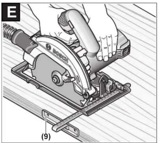
Sawing with a parallel guide (see figure E)
The parallel guide (9) allows you to make precise cuts along the edge of a workpiece and cut strips with the same dimensions.
Loosen the wing bolt (6) and slide the scale of the parallel guide (9) through the guide in the base plate (11). Adjust the desired cutting width as a scale value at the corresponding (8) or (7) cut mark, see the section "Cut marks".
Retighten the wing bolt (6).
Sawing with an auxiliary guide (see figure F)
For working on large workpieces or for cutting straight edges, you can securely fasten a board or rail to the workpiece as an auxiliary guide. The circular saw can be guided along the path of this auxiliary guide with the base plate.
Maintenance and Servicing
Maintenance and cleaning
▶ Pull the plug out of the socket before carrying out any work on the power tool.
▶ To ensure safe and efficient operation, always keep the power tool and the ventilation slots clean.
The retracting blade guard must always be able to move freely and retract automatically. It is therefore important to keep the area around the retracting blade guard clean at all times. Remove dust and chips by blowing out with compressed air or using a brush.
Non-coated saw blades can be protected against corrosion using a thin layer of acid-free oil. Remove the oil again before sawing as failure to do so will stain the wood.
Resin or glue residue on the saw blade has a detrimental effect on the quality of the cut. You should therefore clean saw blades straight after use.
In order to avoid safety hazards, if the power supply cord needs to be replaced, this must be done by Bosch or by a customer service centre that is authorised to repair Bosch power tools.
After-sales Service and Advice on Using Products
Our after-sales service can answer questions concerning product maintenance and repair, as well as spare parts. You can find exploded drawings and information on spare parts
12 | English
at: www.bosch-pt.com
The Bosch product use advice team will be happy to help you with any questions about our products and their accessories.
www.powertool-portal.de, the internet portal for tradespeople and DIY enthusiasts.
In all correspondence and spare parts orders, please always include the 10-digit article number given on the type plate of the product.
Cambodia
Robert Bosch (Cambodia) Co., Ltd
Unit 8BC, GT Tower, 08th Floor, Street 169,
Czechoslovakia Blvd, Sangkat Veal Vong
Khan 7 Makara, Phnom Penh
VATTIN: 100 169 511
Tel.: +855 23 900 685
Tel.: +855 23 900 660
www.bosch.com.kh
People's Republic of China
China Mainland
Bosch Power Tool (China) Co. Ltd.
Bosch Service Center
567, Bin Kang Road
Bin Kang District
Hangzhou, Zhejiang Province
China 310052
Tel.: (0571) 8887 5566 / 5588
Fax: (0571) 8887 6688 x 5566# / 5588#
E-mail: bsc.hz@cn.bosch.com
www.bosch-pt.com.cn
HK and Macau Special Administrative Regions
Robert Bosch Co. Ltd.
21st Floor, 625 King's Road
North Point, Hong Kong
Customer Service Hotline: +852 2101 0235
Fax: +852 2590 9762
E-mail: info@hk.bosch.com
www.bosch-pt.com.hk
India
Bosch Service Center
69, Habibullah Road, (next to PSBB School), T. Nagar
Chennai-600077
Phone: (044) 64561816
Bosch Service Center Rishyamook
85A, Panchkuin Road
New Delhi-110001
Phone: (011) 43166190
Bosch Service Center 79,
Crystal Bldg., Dr. Annie Besant Road, Worli
Mumbai-400018
Phone: (022) 39569936 / (022) 39569959 /
(022) 39569967 / (022) 24952071
Indonesia
PT Robert Bosch
Palma Tower 10th Floor
Jalan RA Kartini II-S Kaveling 6
Pondok Pinang, Kebayoran Lama
Robert Bosch Middle East FZE – Pakistan Liaison Office
2nd Floor Plaza # 10, CCA Block, DHA Phase 5
Lahore, 54810
Phone: +92(303)4444311
E-mail: Faisal.Khan@bosch.com
Philippines
Robert Bosch, Inc.
28th Floor Fort Legend Towers,
3rd Avenue corner 31st Street,
Fort Bonifacio, Global City,
1634 Taguig City
Tel.: (632) 8703871
Fax: (632) 8703870
www.bosch-pt.com.ph
Singapore
Powerwell Service Centre Ptd Ltd
Bosch Authorised Service Centre (Power Tools)
4012 Ang Mo Kio Ave 10, #01-02 TECHplace
Singapore 569628
Tel.: 6452 1770
Fax: 6452 1760
E-mail: ask@powerwellsc.com
www.powerwellsc.com
www.bosch-pt.com.sg
Thailand
Robert Bosch Ltd.
Liberty Square Building
No. 287, 11 Floor
Silom Road, Bangrak
Bangkok 10500
Tel.: 02 6393111
Fax: 02 2384783
Robert Bosch Ltd., P. O. Box 2054
Bangkok 10501
www.bosch.co.th
Bosch Service – Training Centre
La Salle Tower Ground Floor Unit No.2
10/11 La Salle Moo 16
Srinakharin Road
Bangkaew, Bang Plee
Samutprakarn 10540
Tel.:027587555
Fax: 02 7587525
Vietnam
Branch of Bosch Vietnam Co., Ltd in HCMC
14th floor, Deutsches Haus, 33 Le Duan
Ben Nghe Ward, District 1, Ho Chi Minh City
Tel.: (028) 6258 3690
Fax: (028) 6258 3692 - 6258 3694
Hotline: (028) 6250 8555
E-mail: tuvankhachhang-pt@vn.bosch.com
www.bosch-pt.com.vn
Armenia, Azerbaijan, Georgia, Kyrgyzstan, Mongolia,
Tajikistan, Turkmenistan, Uzbekistan
TOO "Robert Bosch" Power Tools, After Sales Service
Rayimbek Ave., 169/1
050050, Almaty, Kazakhstan
Service e-mail: service.pt.ka@bosch.com
Official website: www.bosch.com, www.bosch-pt.com
Bahrain
Hatem Al Juffali Technical Equipment Establishment.
Kingdom of Bahrain, Setra Highway, Al Aker Area
Phone:+966126971777-311
Fax: +97317704257
E-mail: h.berjas@eajb.com.sa
Egypt
Unimar
20 Markaz kadmat
El tagmoa EL Aoul - New Cairo
Phone:+20 2224 76091-95
Phone: +20 2224 78072-73
Fax:+20222478075
E-mail: adelzaki@unimaregypt.com
Iran
Robert Bosch Iran
3rd Floor, No 3, Maadiran Building
Aftab St., Khodami St., Vanak Sq.
Tehran 1994834571
Phone: +9821 86092057
Iraq
Sahba Technology Group
Al Muthana airport road
Baghdad
Phone: +9647901906953
Phone Dubai: +97143973851
E-mail: bosch@sahbatechnology.com
Jordan
Roots Arabia – Jordan
Nasser Bin Jameel street, Building 37 Al Rabiah
11194 Amman
Phone:+962 6 5545778
E-mail: bosch@rootsjordan.com
Kuwait
Al Qurain Automotive Trading Company
Shuwaikh Industrial Area, Block 1, Plot 16, Street 3rd
P.O. Box 164 - Safat 13002
Phone: 24810844
Fax: 24810879
E-mail: josephkr@aaalmutawa.com
Lebanon
Tehini Hana & Co. S.A.R.L.
P.O. Box 90-449
Jdeideh
Dora-Beirut
Phone: +9611255211
E-mail: service-pt@tehini-hana.com
Libya
El Naser for Workshop Tools
Swanee Road, Alfalah Area
Tripoli
Phone: +218 21 4811184
Oman
Malatan Trading & Contracting LLC
P.O. Box 131
Ruwi, 112 Sultanate of Oman
Phone: +968 99886794
E-mail: malatanpowertools@malatan.net
Qatar
International Construction Solutions W L L
P.O.Box 51,
Doha Phone: +974 40065458
Fax: +974 4453 8585
E-mail: csd@icsdoha.com
Saudi Arabia
Juffali Technical Equipment Co. (JTECO)
Kilo 14, Madinah Road, Al Bawadi District
Jeddah 21431
Phone: +966 2 6672222 Ext. 1528
Fax: +966 2 6676308
E-mail: roland@eajb.com.sa
Syria
Dallal Establishment for Power Tools
P.O. Box 1030
Aleppo
Phone: +963212116083
E-mail: rita.dallal@hotmail.com
United Arab Emirates
Central Motors & Equipment LLC, P.O. Box 1984
Al-Wahda Street – Old Sana Building
Sharjah
Phone: +971 6 593 2777
Fax: +971 6 533 2269
E-mail: powertools@centralmotors.ae
Yemen
Abualrejal Trading Corporation
Sana'a Zubiery St. Front to new Parliament Building
Phone: +967-1-202010
Fax: +967-1-279029
E-mail: tech-tools@abualrejal.com
Ethiopia
Forever plc
Kebele 2,754, BP 4806,
Addis Ababa
Phone: +251 111 560 600
E-mail: foreverplc@ethionet.et
Ghana
14 | Français
C.WOERMANN LTD.
Nsawam Road/Avenor Junction, P.O. Box 1779
Accra Phone: +233 302 225 141
Kenya
Robert Bosch East Africa Ltd
Mpaka Road P.O. Box 856
00606 Nairobi
Nigeria
Robert Bosch Nigeria Ltd.
52–54 Isaac John Street P.O. Box
GRA Ikeja - Lagos
Republic of South Africa
Customer service
Hotline: (011) 6519600
Gauteng - BSC Service Centre
35 Roper Street, New Centre
Johannesburg
Tel.: (011) 4939375
Fax: (011) 4930126
E-mail: bsctools@icon.co.za
KZN - BSC Service Centre
Unit E, Almar Centre
143 Crompton Street
Pinetown
Tel.: (031) 7012120
Fax: (031) 7012446
E-mail: bsc.dur@za.bosch.com
Western Cape - BSC Service Centre
Democracy Way, Prosperity Park
Milnerton
Tel.: (021) 5512577
Fax: (021) 5513223
E-mail: bsc@zsd.co.za
Bosch Headquarters
Midrand, Gauteng
Tel.: (011) 6519600
Fax: (011) 6519880
E-mail: rbsa-hq.pts@za.bosch.com
Tanzania
Diesel & Autoelectric Service Ltd.
117 Nyerere Rd., P.O. Box 70839
Vingunguti 12109, Dar Es Salaam
Phone: +255 222 861 793/794
Australia, New Zealand and Pacific Islands
Robert Bosch Australia Pty. Ltd.
Power Tools
Locked Bag 66
Clayton South VIC 3169
Customer Contact Center
Inside Australia:
Phone: (01300) 307044
Fax: (01300) 307045
Inside New Zealand:
Phone: (0800) 543353
Fax: (0800) 428570
Outside AU and NZ:
Phone: +61 3 95415555
www.bosch-pt.com.au
www.bosch-pt.co.nz
Disposal
The power tool, accessories and packaging should be recycled in an environmentally friendly manner.

Do not dispose of power tools along with household waste.
Français
Robert Bosch Morocco SARL
53, Rue Lieutenant Mahroud Mohamed
20300 Casablanca
E-Mail: sav.outillage@ma.bosch.com
Tunisie
Robert Bosch Tunisie SARL
Palma Tower 10th Floor
Jalan RA Kartini II-S Kaveling 6
Pondok Pinang, Kebayoran Lama
Đơn nguyên 8BC, GT Tower, Tâng 08,
Đường 169, Tiếp Khắc Blvd, Sangkat Veal Vong, Khan 7 Makara, Phnom Penh
VAT TIN: 100 169 511
Tel.: +855 23 900 685
Tel.: +855 23 900 660
www.bosch.com.kh
Sự thải bổ
+216 71 427 496/879: م forecasts
natural_image
Technical line drawing of a mechanical cutting tool with a circular cutter and base plate (no text or symbols)+

+
→
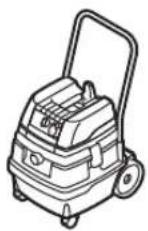
GAS 25
GAS 50
GAS 50 M
GAS 15 L
natural_image
Technical line drawing of a mechanical cutting tool with a circular cutter and base plate (no text or symbols)+

+
GAS 25
GAS 50
GAS 50 M
GAS 15 L
2 608 000 563
∅ 35 mm
3m 2607002163
5m 2607002164
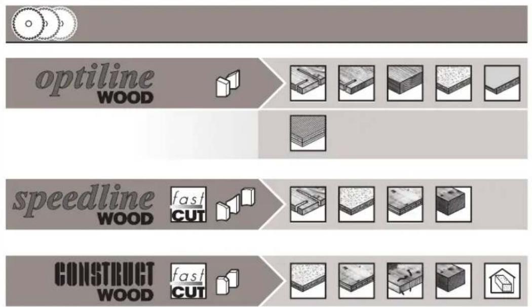
flowchart
graph LR
    A["optiline"] --> B["speedline"]
    B --> C["CONSTRUCT"]
    subgraph "optiline_WOOD"
        D["Wood Shape 1"]
        E["Wood Shape 2"]
        F["Wood Shape 3"]
    end
    subgraph "speedline_WOOD"        G["Fast Cut"]
        H["Fast Cut"]
    end
    subgraph "CONSTRUCT_WOOD"        I["Fast Cut"]
        J["Fast Cut"]
    end