SPEECH-500/GR - Powered lectern Monacor - Free user manual and instructions
Find the device manual for free SPEECH-500/GR Monacor in PDF.


User questions about SPEECH-500/GR Monacor
0 question about this device. Answer the ones you know or ask your own.
Ask a new question about this device
Download the instructions for your Powered lectern in PDF format for free! Find your manual SPEECH-500/GR - Monacor and take your electronic device back in hand. On this page are published all the documents necessary for the use of your device. SPEECH-500/GR by Monacor.
USER MANUAL SPEECH-500/GR Monacor
natural_image
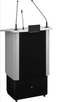
Exterior view of a modern office podium with black and white panels and two microphones (no text or symbols visible)SPEECH-500/GR
English ...... Page 8
Français ...... Page 12
text_image
UHF-PLL TX AF LEVEL SET OFF MAX.③ Sendemodul
AUDIO IN, Cinch: 400 mV
Lectern with Amplifier System
These instructions are intended for users without any special technical knowledge. Please read the instructions carefully prior to operation and keep them for later reference. All operating elements and connections described can be found on page 2.
1 Overview
1 Input MIC 1 (XLR jack) with 24 V phantom power to connect a microphone to input channel 1 [as an alternative to the jack (18) on the rear]
2 XLR jack to connect a gooseneck light to illuminate the reading surface
3 Screw to fasten the name plate of the person speaking
4 Input MIC 2 (XLR jack) with 24 V phantom power to connect a microphone to input channel 2 (as an alternative to the jack on the rear)
5 Reading surface with glass plate
6 Compartment for a laptop/tablet computer or for notes; the flap of the compartment can be locked in various positions
7 Switch for illumination of the compartment (2 brightness levels) and for an additional gooseneck light connected to the XLR jack (2)
8 Power strip
9 Rocker switch LIFT to adjust the height of the lectern
10 Transmitter module for wireless transmission of the mixed signal, e. g. to another amplifier system
11 Receiver module for two wireless microphones
12 Shelves; e. g. for lecture papers / notes and this in struction manual
13 POWER switch
14 Mains jack for connection to a socket (230 V/50 Hz) via the mains cable provided
15 Support for the mains fuse Always replace a blown fuse by one of the same type!
16 VOLUME control, for each input channel 1–4
The control for channel 3 is also used to adjust the volume of the wireless receiver.
17 The LED RF has no function.
18 Combined XLR / 6.3 mm jack to connect a microphone via an XLR plug or an audio source with line level via a two-pole 6.3 mm plug for each input channel 1 – 3
The XLR contacts of the input channels 1 and 2 are supplied with 24 V phantom power, e. g. for electret microphones.
19 Equalizer controls HIGH, MID an LOW for each channel 1–3
20RCA inputs AUDIO IN to connect an audio source with line level to input channel 4; when both jacks are connected (e.g. stereo signal from a CD player), the signals will create the sum (mono)
21 Output LINE OUT, REC (RCA jacks) to route the mixed signal, e. g. to a recorder or another amplifier system
22 LED LIMITER; will light up when the input level is too high and is reduced by the limiter
23 POWER LED
2 Safety Notes
The product corresponds to all relevant directives of the EU and is therefore marked with €€
WARNING

The product uses dangerous mains voltage. Leave servicing to skilled personnel. Inexpert handling may result in electric shock.
- The product is suitable for indoor use only. Protect it against dripping water, splash water and high air humidity. The admissible ambient temperature range is 0 – 40 °C.
-
Do not operate this product and immediately disconnect the mains plug from the socket
-
if the lectern or the mains cable is visibly damaged,
- if a defect might have occurred the after product was dropped or suffered a similar accident,
- if malfunctions occur.
Any repairs must be carried out by specialists.
- Never pull the mains cable to disconnect the mains plug from the socket, always seize the plug.
- For cleaning only use a dry, soft cloth; never use water or chemicals.
- No guarantee claims for the product and no liability for any resulting personal damage or material damage will be accepted if the product is not correctly used, if it is not securely set up or not expertly repaired.

If the product is to be put out of operation definitely, dispose of the product in accordance with local regulations.
3 Applications
The lectern SPEECH-500/GR consists of a high-quality 2-way speaker system, a mixing amplifier with four input channels and a receiver module for two wireless microphones. It is ideally suited to reproduce sound, e.g. for lectures, speeches, readings etc. The optional wireless microphones offer additional mobility (e.g. for passing round the microphones in the audience when questions arise).
In addition to three microphones, it will also be possible to connect other audio units (e.g. CD player for adding music). Via the jacks LINE OUT, REC, the output signal will be routed to a recorder or to another amplifier system. The lectern also offers a wireless transmitter for wireless transmission, for example, to another amplifier system.
The glass plate of the reading surface allows the person speaking to see a laptop / tablet computer or notes in the compartment underneath. The integrated illumination of the compartment underneath the glass plate offers two brightness levels. In addition, a gooseneck light can be connected to the lectern to illuminate the reading surface.
The height of the lectern is electrically adjustable. The lectern is equipped with four castors and can therefore be easily transported.
3.1 Wireless microphones and transmitters
The following units are available from MONACOR:
| Type | Model |
| Hand-held wireless microphone | TXA-800HT |
| Pocket transmitter with tie clip microphone and head-band microphone | TXA-800HSE |
| Transmitter with line level input for audio signals | TXA-800ST |
3.2 Conformity and approval
Herewith, MONACOR INTERNATIONAL declare that the product SPEECH-500/GR complies with the directive 2014 /53 / EU. The EU declaration of conformity is available on the Internet:
www.monacor.com
The product is generally approved for operation in EU and EFTA countries, it is licence-free and requires no registration.
4 Transport and Setting up
For transport, the lectern is equipped with four castors. The two rear castors are swivel castors with locking brakes. Thus, it will be easy to wheel it to the place of application. Set up the lectern is such a way that the speakers on its front will be directed towards the audience. Place the lectern and lock the brakes of its castors. A name plate is supplied with the lectern. If required, fasten the name plate of the person speaking to the front of the lectern using the screw (3).
5 Connections
Prior to connecting any units or to changing any existing connections, switch off the amplifier system and all units to be connected.
5.1 Microphones and audio unit
1) Connect a microphone (e. g. a suitable gooseneck microphone from the EMG...P series) to one of the XLR jacks (1 or 4) on the upper side of the lectern and adjust it to the person speaking. It will also be possible to equip both jacks with one microphone each. The jacks have a latching mechanism; to disconnect the plug, press the PUSH lever.
As an alternative, connect a microphone with XLR plug to the input jack (18) of the channels 1 and 2 on the rear of the lectern. Like the jacks on the upper side of the lectern, these microphone inputs will supply the phantom power (24 V) required by some microphones.
The input jack of channel 3 allows connection of another microphone with XLR plug.
2) To connect an audio source with line level (e. g. mixer, CD player), use the 6.3 mm jacks (18) of the input channels 1–3 (if the corresponding channel is not used by a microphone) or the RCA jacks AUDIO IN (20) of channel 4. When both RCA jacks are connected (e. g. stereo signal from a CD player), the signals will create the sum (mono).
Note: If you use any wireless microphones, their signals will be mixed to the input signal of channel 3.
5.2 Recorder or
additional amplifier system
The RCA jacks of the output LINE OUT, REC (21) allow connection of a recorder or another audio unit with line level input (e.g. an additional amplifier system for PA applications in large zones). The mixed signal of the audio sources will be available at these jacks.
In addition, wireless transmission of the output signal by means of the integrated transmitter module, for example, to another amplifier system with a corresponding wireless receiver will be possible (Chapter 6.2).
5.3 Gooseneck light
To illuminate the reading surface, connect a 12 V gooseneck light with a maximum power of 6 W (e. g. GNL-453XLR or GNL-304) to the XLR jack (2). The XLR jack has a latching mechanism. To remove the light, press the PUSH lever.
5.4 Power supply
Connect the power supply cable provided to the mains jack (14) and connect the mains plug to a socket (230 V/ 50 Hz).
A power strip (8) is provided to supply power to additional devices.
6 Operation
1) Before switching on, set the VOLUME controls (16) of all four input channels to "0" to prevent switching noise and to make sure that the volume is not too high.
2) Switch on the audio sources connected first, then switch on SPEECH-500/GR with the POWER switch (13). The POWER LED (23) will light up. If an additional amplifier system for PA applications has been connected to SPEECH-500/GR, switch on this amplifier system last.
After operation, switch off the units in reverse order:
-
the additional amplifier system
-
SPEECH-500/GR
-
the audio sources connected
3) Mix the signals of the input channels with the corresponding VOLUME controls (16) or fade them in and out as required. When using wireless microphones, also see chapter 6.1. Only adjust the volume to such a level that the sound reproduced will not be distorted.
If the LED LIMITER (22) lights up frequently, the input level is too high and should be reduced with the corresponding volume control.
CAUTION

Make sure to use an adequate volume level. Permanent high volumes may damage your hearing.
To prevent feedback howl, never direct the microphone towards the speaker and never place it too close to the speaker. Feedback may also occur when the volume is too high. In this case, reduce the microphone volume with the corresponding VOLUME control (16).
4) To optimize the sound for the channels 1–3, use the corresponding equalizer controls HIGH, MID and LOW (19). After modifying the sound, readjust the volume with the corresponding VOLUME control (16), if required.
6.1 Operation with wireless microphones
The lectern is equipped with a receiver module (11) for two wireless microphones / transmitters.
text_image
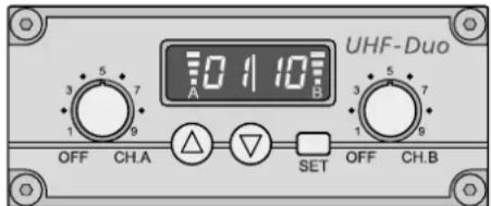
UHF-Duo 10 11 10 A B 3 5 7 1 9 OFF CH.A △ ▽ SET OFF CH.B② Wireless receiver module
Each receiver section (A and B) is equipped with a control to adjust the volume and to switch it on and off (fig. 2). The display is divided into two parts: left half for receiver section A, right half for receiver section B. When a receiver section has been switched on, the display will indicate the transmission channel. To briefly indicate the radio frequency, press the button (for section A) or (for section B).
6.1.1 Setting the transmission channels
Use the controls to switch on the receiver sections. Do not switch on the corresponding wireless microphones / transmitters for the time being.
6.1.1.1 Channel scan
Keep the buttons and simultaneously pressed for approx. 1 second until 5 n pears on the display. The scan will start: The receiver sections will be set to free channels without mutual interference. If no free channels are found, the channels set will be kept.
Note: The channel scan can also be started for one section only (button △ for section A or button ▽ for section B).
6.1.1.2 Manual channel selection
When both receiver sections A and B are switched on:
1) Keep the button SET pressed until the channel indication for receiver section A starts flashing on the display.
2) Select the channel for receiver section A with the button or and then confirm with the button SET.
3) The channel indication for receiver section B starts flashing on the display. Select the channel for receiver section B with the button or and then confirm with the button SET.
When only one receiver section A or B is switched on:
Keep the button SET pressed until the channel indication starts flashing on the display. Select the channel with the button or and then confirm with the button SET.
Notes:
- The receiver sections cannot be set to the same channel.
- If a channel is not confirmed within 10 seconds with the button SET, the setting mode will be exited and the channel previously set will be kept.
- If, with the transmitter switched off, the respective segment bar A or B on the display indicates reception, interference signals or signals from other transmitters are being received. In this case, use a different channel.
6.1.2 Adjusting the volume
Switch on the wireless microphones / transmitters and set one to the channel of receiver section A and the other to the channel of receiver section B. The respective segment bars on the display will then indicate the strength of the radio signals received. Use the controls to adjust the desired volume for each receiver section.
Adjust the total volume of the audio signals received with the VOLUME control (16) of input channel 3. If a microphone or another audio source has been connected to the input jack (18) of the third channel, the signals will be mixed.
Notes
- If you do not receive a signal from the wireless microphone, make sure that the microphone is transmitting on the correct frequency (channel) and check the battery of the microphone. Reduce the distance between the lectern and the microphone, if required.
- If reception is poor, turning or moving the lectern may improve it.
6.1.3 Setting the squelch
The squelch function will mute the respective receiver section when the level of the radio signal falls below the threshold value adjusted. Thus, interference signals will not cause noise when the transmitter is switched off or when its radio signal is poor: If the levels of the interference signals are below the threshold value, the receiver section will be muted. A high threshold value offers high interference resistance, but it will also reduce the transmission range.
1) Switch off the receiver sections A and B. Then keep the button SET pressed while switching on a receiver section. The display will indicate F or ,F with the number flashing.
2) Press the button SET to activate the squelch setting mode: 5 (for "Squelch") and the current value (flashing) will appear on the display.
3) Use the button or to set the value (level 7 = highest threshold value). Press the button SET to exit the squelch setting mode.
Note: The setting modes will be automatically exited after 5 seconds if no button is pressed. Any settings made will be saved.
6.2 Transmitter module
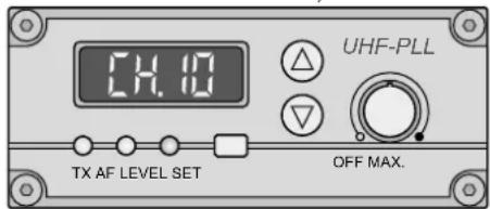
The transmitter module (10) is used for wireless transmission of the mixed signal to a receiver matched to the same radio frequency (e.g. pocket transmitter TXA-800R or receiver module of a portable amplifier system from series TXA-820 or TXA-1020).
text_image
UHF-PLL TX AF LEVEL SET OFF MAX.③ Transmitter module
To establish the transmission path, do not switch on the transmitter module for the time being; first, set the corresponding receiver to an interference-free transmission channel (D) instructions of the receiver).
6.2.1 Setting the transmission channel
1) Use the rotary control to switch on the transmitter module. The LED TX will light up.
2) Press the button SET: The channel indication on the display will start flashing.
3) As long as the channel indication keeps flashing (10 seconds), the button or can be used to select the channel.
Set the transmitter module to the channel of the receiver.
Important: If the transmitter module and the wireless receiver module of the lectern are used at the same time, set the modules to different channels; otherwise, there will be feedback.
4) Confirm the channel selected with the button SET (otherwise, the transmitter module will return to the set previously channel after 10 seconds).
To briefly indicate the radio frequency during operation, keep the buttons or pressed: The display will indicate the frequency instead of the channel while the arrow button is pressed.
6.2.2 Adjusting the transmission volume
Use the rotary control to adjust the desired volume of the signal transmitted.
The LEDs AF LEVEL will indicate the signal level at the input of the transmitter module. The red overload LED should only briefly light up for signal peaks. If the LED lights permanently, reduce the volume of the corresponding audio source(s) with the corresponding controls (16) to avoid distortion.
6.3 Illumination
To switch on the integrated illumination of the compartment (6) underneath the glass plate (5), set the switch (7) to position "I" or "II" according to the desired brightness level. This switch is also used for a gooseneck light connected to the XLR jack (2) to illuminate the reading surface.
6.4 Height adjustment of the lectern
With the integrated motor, the height of the lectern is easily adapted to the person speaking. To adjust the height, use the rocker switch LIFT (9) to increase or reduce the height.
The scale on the left next to ▶ LEVEL will indicate the current height of the lectern.
7 Specifications
Amplifier power
Rated power: 50W
Peak power: 100W
Speaker
Bass speaker: .... 0 30 cm (12")
Horn tweeter: 2.5 cm (1")
Frequency range: 50–20 000 Hz
Wireless receiver sections: ..... 2
Wireless transmitter sections: . . . 1
Transmitting power: .... ≤ 10 mW
Frequencies transmitted and received
| Channel Frequency Channel Frequency | ||
| 01 | 863.1 MHz 09 | 863.2 MHz |
| 02 864.1 MHz 10 864.2 MHz | ||
| 03 863.6 MHz 11 863.7 MHz | ||
| 04 864.6 MHz 12 864.7 MHz | ||
| 05 863.3 MHz 13 863.4 MHz | ||
| 06 864.3 MHz 14 864.4 MHz | ||
| 07 863.8 MHz 15 863.9 MHz | ||
| 08 864.8 MHz 16 864.9 MHz | ||
Wireless transmission range: . . . approx. 30 m
Input sensitivity
MIC 1, MIC 2
(XLR jacks, top): 24mV
Microphone input of channels 1–3
(XLR jacks, rear): 4.5mV
JACK-LINE, 6.3 mm jack: ..... 150 mV
AUDIO IN, RCA: 400 mV
Pin configuration of the microphone inputs, XLR
Channels 1 and 2:
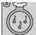
| 1 ground | |
| 2 | signal +, +24 V phantom power |
| 3 | signal -, +24 V phantom power |
| 1 ground | |
| 2 | signal +, +24 V phantom power |
| 3 | signal -, +24 V phantom power |
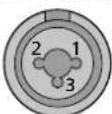
Channel 3:
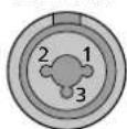
| 1 ground | |
| 2 | signal+ |
| 3 | signal- |
Pin configuration of the line inputs, 6.3 mm jack:
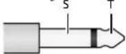
| S | ground |
| T | signal |
Output LINE OUT, REC:....320mV
Equalizer
LOW:....±12 dB at 60 Hz
MID:....±7dB at 1 kHz
HIGH:....±12dB at 15kHz
XLR jack for the gooseneck light:
| 1 ground | |
| 2 | +12V, 0.5A max. (6W) |
Power supply: 230V/50Hz
Power consumption: ..... 135VA max.
Ambient temperature:....0-40°C
Dimensions
Width: 800 mm
Height: 850-1250mm
Depth: 570 mm
Weight: 52 kg
Subject to technical modification.
text_image
14.10 UHF-PLL TX AF LEVEL SET OFF MAX.③ Module émetteur
(prises XLR dessus):.....24mV
Alimentation: 230V/50Hz
Consommation: 135VA max.