PDCF1NBWWW - Fridge GE - Free user manual and instructions
Find the device manual for free PDCF1NBWWW GE in PDF.

User questions about PDCF1NBWWW GE
0 question about this device. Answer the ones you know or ask your own.
Ask a new question about this device
Download the instructions for your Fridge in PDF format for free! Find your manual PDCF1NBWWW - GE and take your electronic device back in hand. On this page are published all the documents necessary for the use of your device. PDCF1NBWWW by GE.
USER MANUAL PDCF1NBWWW GE
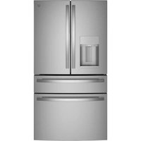
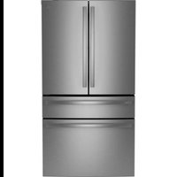
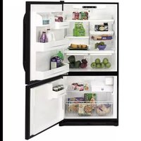
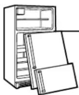
Bottom Freezer Refrigerators
Safety Instructions .....2, 3
Operating Instructions
Additional Features ....8
Automatic Icemaker .....11
Care and Cleaning .....12–13
Controls 4-5
Crispers and Pans .....9
Freezer....10
Replacing the Light Bulbs .....14
Shelves and Bins .....7, 8
Water Filter 6
Installation Instructions
Installing the Anti-Tip
Floor Bracket .....18-19
Installing the Refrigerator . . . 20–24
Installing the Water Line .....33-35
Preparing to Install the Refrigerator .....17
Removing and Replacing the
Freezer Drawer . . . . . . . . . . . . . . . . . . . . . . . . . . . . . . . . . . . . . . . . . . . . . 25, 26
Reversing the Door Swing (Single Door Refrigerator Models only) .....27–29
Removing and Replacing the Doors (Double Door Refrigerator Models only) ....30–32
Trim Kits and Decorator Panels ....15-16
Troubleshooting Tips .....36–40
Normal Operating Sounds .....36
Consumer Support
Consumer Support .....Back Cover
Performance Data Sheet .....47
Product Registration
for Canadian Customers .....43, 44
Product Registration
for U.S. Customers .....41, 42
State of California Water
Treatment Device Certificate .....48
Warranty for Canadian
Customers 46
Warranty for U.S. Customers .....45
Write the model and serial numbers here:
Model #
Serial #
Find these numbers on a label on the right side, near the top of the refrigerator compartment.
Owner's Manual and Installation Instructions
Models 21 and 25
natural_image
Close-up of a stylized white logo design with swirling patterns, no text or symbols visible.200D9366P001 49-60489-2 06-07 JR
IMPORTANT SAFETY INFORMATION. READ ALL INSTRUCTIONS BEFORE USING.
▲ WARNING!
Use this appliance only for its intended purpose as described in this Owner's Manual.

SAFETY PRECAUTIONS
When using electrical appliances, basic safety precautions should be followed, including the following:
This refrigerator must be properly installed and located in accordance with the Installation Instructions before it is used.
Do not allow children to climb, stand or hang on the shelves in the refrigerator. They could damage the refrigerator and seriously injure themselves.
Do not touch the cold surfaces in the freezer compartment when hands are damp or wet. Skin may stick to these extremely cold surfaces.
Do not store or use gasoline or other flammable vapors and liquids in the vicinity of this or any other appliance.
- Keep fingers out of the “pinch point” areas; clearances between the doors and between the doors and cabinet are necessarily small. Be careful closing doors when children are in the area.
In refrigerators with automatic icemakers, avoid contact with the moving parts of the ejector mechanism, or with the heating element that releases the cubes. Do not place fingers or hands on the automatic icemaking mechanism while the refrigerator is plugged in.
■ Unplug the refrigerator before cleaning and making repairs.
NOTE: We strongly recommend that any servicing be performed by a qualified individual.
Setting either or both controls to 0 (off) does not remove power to the light circuit.
Do not refreeze frozen foods which have thawed completely.
▲ DANGER! RISK OF CHILD ENTRAPMENT
PROPER DISPOSAL OF THE REFRIGERATOR
Child entrapment and suffocation are not problems of the past. Junked or abandoned refrigerators are still dangerous...even if they will sit for “just a few days.” If you are getting rid of your old refrigerator, please follow the instructions below to help prevent accidents.
Before You Throw Away Your Old Refrigerator or Freezer:
Take off the doors.
Leave the shelves in place so that children may not easily climb inside.
Refrigerants
All refrigeration products contain refrigerants, which under federal law must be removed prior to product disposal. If you are getting rid of an old refrigeration product, check with the company handling the disposal about what to do.
USE OF EXTENSION CORDS
Because of potential safety hazards under certain conditions, we strongly recommend against the use of an extension cord.
However, if you must use an extension cord, it is absolutely necessary that it be a UL-listed (in the United States) or a CSA certified (in Canada), 3-wire grounding type appliance extension cord having a grounding type plug and outlet and that the electrical rating of the cord be 15 amperes (minimum) and 120 volts.
⚠ WARNING!
HOW TO CONNECT ELECTRICITY
Do not, under any circumstances, cut or remove the third (ground) prong from the power cord. For personal safety, this appliance must be properly grounded.
The power cord of this appliance is equipped with a 3-prong (grounding) plug which mates with a standard 3-prong (grounding) wall outlet to minimize the possibility of electric shock hazard from this appliance.
Have the wall outlet and circuit checked by a qualified electrician to make sure the outlet is properly grounded.
Where a standard 2-prong wall outlet is encountered, it is your personal responsibility and obligation to have it replaced with a properly grounded 3-prong wall outlet.
The refrigerator should always be plugged into its own individual electrical outlet which has a voltage rating that matches the rating plate.
This provides the best performance and also prevents overloading house wiring circuits which could cause a fire hazard from overheated wires.
Never unplug your refrigerator by pulling on the power cord. Always grip plug firmly and pull straight out from the outlet.
Repair or replace immediately all power cords that have become frayed or otherwise damaged. Do not use a cord that shows cracks or abrasion damage along its length or at either end.
When moving the refrigerator away from the wall, be careful not to roll over or damage the power cord.

READ AND FOLLOW THIS SAFETY INFORMATION CAREFULLY.
SAVE THESE INSTRUCTIONS
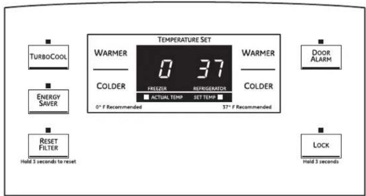
About the controls with temperature settings.

text_image
Energy Saver Door Alarm Warmer Colder Freezer 0 Refrigerator 37° 0° Recommended Temp 37° Colder Warmer Turbo Cool Water Filter Reset Hold 5 Secs(on some models)
text_image
TEMPERATURE SET TURBOCOOL WARMER 0 37 COLDER FREEZER REFRIGERATOR ACTUAL TEMP SET TEMP 0° F Recommended 37° F Recommended DOOR ALARM ENERGY SAVER RESET FILTER Hold 3 seconds to reset LOCK Hold 3 seconds(on some models)
NOTE: The refrigerator is shipped with protective film covering the temperature controls. If this film was not removed during installation, remove it now.
The temperature controls are preset in the factory at 37^ F for the refrigerator compartment and 0^ F for the freezer compartment. Allow 24 hours for the temperature to stabilize to the preset recommended settings.
The temperature controls can display both the SET temperature as well as the actual temperature in the refrigerator and freezer. The actual temperature may vary slightly from the SET temperature based on usage and operating environment.
Setting either or both controls to OFF stops cooling in both the freezer and refrigerator compartments, but does not shut off electrical power to the refrigerator.
Changing the Temperature
For Controls-on-the-Door Models:
To change the temperature, press and release the WARMER or COLDER pad. The ACTUAL TEMP light will come on and the display will show the actual temperature. To change the temperature, tap either the WARMER or COLDER pad until the desired temperature is displayed.
For Controls Inside the Refrigerator:
Opening the door displays the actual temperature. To change the temperature, press either the WARMER or COLDER touch pads until the desired temperature is displayed.
Once the desired temperature has been set, the temperature display will return to the actual refrigerator and freezer temperatures after 5 seconds. Several adjustments may be required.
Each time you adjust controls, allow 24 hours for the refrigerator to reach the temperature you have set.
To turn the cooling system off, tap the WARMER pad for either the refrigerator or the freezer until the display shows OFF. To turn the unit back on, press the COLDER pad for either the refrigerator or freezer. Then press the COLDER pad again and it will go to the preset points of 0°F for the freezer and 37°F for the refrigerator. Setting either or both controls to OFF stops cooling in both the freezer and refrigerator compartments, but does not shut off electrical power to the refrigerator.
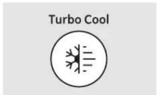
About TurboCool.™ (on some models) ge.com
text_image
Turbo Cool(on some models)
How it Works
TurboCool rapidly cools the refrigerator compartment in order to more quickly cool foods. Use TurboCool when adding a large amount of food to the refrigerator compartment, putting away foods after they have been sitting out at room temperature or when putting away warm leftovers. It can also be used if the refrigerator has been without power for an extended period.

(on some models)
Once activated, the compressor will turn on immediately and the fans will cycle on and off at high speed as needed for eight hours. The compressor will continue to run until the refrigerator compartment cools to approximately 34^ F ( 1^ C), then it will cycle on and off to maintain this setting. After 8 hours, or if TurboCool is pressed again, the refrigerator compartment will return to the original setting.
How to Use
Press TurboCool. The refrigerator temperature display will show bc
After TurboCool is complete, the refrigerator compartment will return to the original setting.
NOTES: The refrigerator temperature cannot be changed during TurboCool.
The freezer temperature is not affected during TurboCool.
When opening the refrigerator door during TurboCool, the fans will continue to run if they have cycled on.
text_image
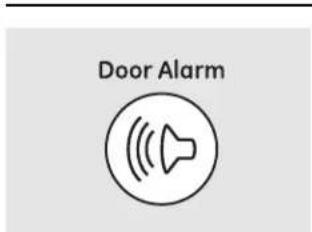
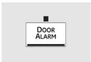
Door Alarm(on some models)
About Door Alarm (on some models)
The door alarm will sound if any door is open for more than 2 minutes. The beeping stops when you close the door.
text_image
DOOR ALARM(on some models)

(on some models)
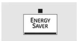
About Energy Saver (on some models)
This product is equipped with an Energy Saver feature. The refrigerator is shipped with the Energy Saver feature enabled.
Over time, moisture can form on the front surface of the refrigerator cabinet and cause rust. If moisture does appear on the front surface of the refrigerator cabinet, turn off the Energy Saver feature by pressing and releasing the ENERGY SAVER pad on the control panel.
text_image
ENERGY SAVER(on some models)
About the water filter. (on some models)
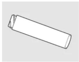
natural_image
Simple line drawing of a cylindrical object with a cut section, no text or symbols present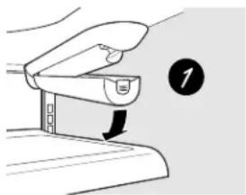
natural_image
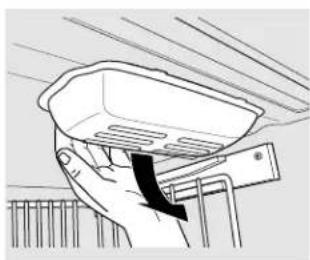
Illustration of a hand holding a device with a downward arrow, no text or symbols present
natural_image
Diagram of a hand gripping a device with a circular arrow and number 2 (no text or symbols on the diagram itself)
natural_image
Diagram of a hand gripping a device with a circular arrow and number 4, no text or symbols present
text_image
Water Filter Reset Hold 3 Secs(on some models)
text_image
RESET FILTER Hold 3 seconds to reset(on some models)
Water Filter Cartridge
The water filter cartridge is located in the back upper right corner of the refrigerator compartment.
When to Replace the Filter
There is a replacement indicator light for the water filter cartridge on the temperature display. This light will turn orange to tell you that you need to replace the filter soon. The filter cartridge should be replaced when the replacement indicator light turns red or if the flow of water to the dispenser or icemaker decreases.
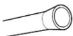
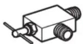
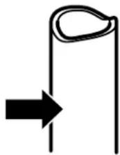
Installing the Filter Cartridge
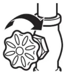
If you are replacing the cartridge, first remove the old one. Open the cartridge cover by pressing in on the tab at the front and pulling down.
2 Remove the cartridge by slowly rotating it counterclockwise. A small amount of water may drip down.
CAUTION: If air has been trapped in the system, the filter cartridge may be ejected as it is removed. Use caution when removing.
3 Remove the protective foil from the end of the cartridge.
4 Lining up the arrow on the cartridge and the cartridge holder, slowly rotate the cartridge clockwise until it stops. When the cartridge is properly installed, you will feel it "click" as it locks into place. The grip on the end of the cartridge should be positioned vertically. Do not overtighten.
5 Close the cartridge cover.
6 Run water from the dispenser for 3 minutes (about 1 12 gallons) to clear the system and prevent sputtering. See To Use the Dispenser section.
7 Press and hold the RESET WATER FILTER pad for 3 seconds.
NOTE: A newly-installed water filter cartridge may cause water to spurt from the dispenser.
Filter Bypass Plug
You must use the filter bypass plug when a replacement filter cartridge is not available. The icemaker will not operate without the filter or filter bypass plug.
Replacement Filters:
To order additional filter cartridges in the United States, visit our Website, ge.com, or call GE Parts and Accessories, 800.626.2002.
Filter Model GSWF
Customers in Canada should consult the yellow pages for the nearest Mabe Service Center.
About the shelves and bins. ge.com
Not all features are on all models.
Rearranging the Shelves
Shelves in the refrigerator compartment are adjustable.

text_image
Diagram showing two labeled arrows pointing to a rectangular object with a handle, likely illustrating a process or assembly.Some models have wire shelves that can be adjusted in the same manner.
Refrigerator Compartment
To remove:
1 Remove all items from the shelf.
② Tilt the shelf up at the front.
3 Lift the shelf up at the back and bring the shelf out.
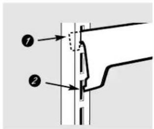
text_image
Technical diagram showing two labeled components (① and ②) with directional arrows indicating flow or movement.To replace:
7 While tilting the shelf up, insert the top hook at the back of the shelf in a slot on the track.
2 Lower the front of the shelf until the bottom of the shelf locks into place.
natural_image
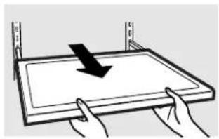
Simple line drawing of a rectangular object with hands extending into it, no text or symbols present.Spillproof Shelves (on some models)
Spillproof shelves have special edges to help prevent spills from dripping to lower shelves. To remove or replace the shelves, see Rearranging the Shelves.
natural_image
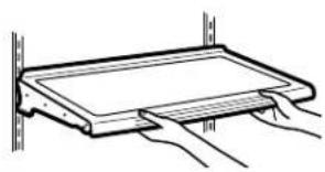
Illustration of hands holding a tray with a downward arrow, no text or symbols presentSlide-Out Spillproof Shelf (on some models)
The slide-out spillproof shelf allows you to reach items stored behind others. The special edges are designed to help prevent spills from dripping to lower shelves.
To remove:
1 Remove all items from shelf.
② Slide the shelf out until it stops.
3 Lift the front edge of the shelf until the central tabs are above the front bar.
4 Continue pulling the shelf forward until it can be removed.
To replace:
1 Place the rear shelf tabs just in front of the central notches on the shelf frame.
② Slide the shelf in until the central tabs are slightly behind the front bar.
3 Lower the shelf into place until it is horizontal and slide the shelf in.
Make sure that the shelf sits flat after reinstallation and doesn't move freely from side to side.
Make sure you push the shelves all the way in before you close the door.
About the shelves and bins.
natural_image
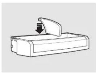
Line drawing of a rectangular device with an open lid and a downward arrow indicating a drop or compression (no text or symbols)Adjustable Bins on the Door
Adjustable bins can easily be carried from refrigerator to work area.
To remove: Lift bin straight up, then pull out.
To replace or relocate: Slide in the bin just above the molded door supports, and push down. The bin will lock in place.
The snugger helps prevent tipping, spilling or sliding of small items stored on the door shelf. Grip the finger hold near the rear of the snugger and move it to fit your needs.

natural_image
Simple line drawing of a rectangular device with a downward arrow indicating motion or force (no text or symbols)Non-Adjustable Bins on the Door
To remove: Lift the bin straight up, then pull out.
To replace: Engage the bin in the molded supports on the door and push down. It will lock in place.
About the additional features.
Not all features are on all models.

natural_image
Technical line drawing of a mechanical component with internal channels (no text or symbols)Non-Adjustable Beverage Rack
To remove: Lift the rack straight up, then pull out.
To replace: Engage the rack in the molded supports on the door and push down. It will lock in place.
About the crispers and pans. ge.com
Not all features are on all models.
natural_image
Line drawing of a cabinet or storage unit with no text or symbolsFruit and Vegetable Crisper
Excess water that may accumulate in the bottom of the drawers or under the drawers should be wiped dry.

natural_image
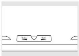
Pure technical line drawing of a symmetrical mechanical or architectural component with two rectangular cutouts and two circular holes (no text or symbols)Adjustable Humidity Crisper (on some models)
Slide the control all the way to the HIGH setting to provide high humidity recommended for most vegetables.
Slide the control all the way to the LOW setting to provide lower humidity levels recommended for most fruits.
text_image
Color RedAdjustable Temperature Deli Pan (on some models)
Slide the control all the way to the left for the coldest temperature.
natural_image
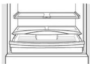
Line drawing of a multi-tiered storage unit or rack with no text or symbolsHow to Remove and Replace the Deli Pan
To remove:
7 Remove the fruit and vegetable drawers.
2 Pull the drawer out to the stop position.
To replace:
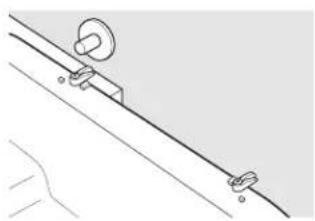
7 Make sure all four swing locks are in the unlock position.
2 Place the sides of the drawer into the drawer supports, making sure the swing locks fit on the drawer slots.
3 Lock all four swing locks by rotating them to the lock position.
natural_image
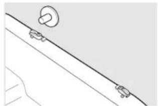
Simple line drawing of a diagonal line with two small car icons on one end, no text or symbols present.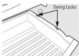
text_image
Swing Locks3 Lift the lid to access the 4 swing locks.
4 Rotate all four swing locks to the unlock position.
5 Lift the front of the drawer up and out.
4 Lower the lid and slide in the drawer.
⑤ Replace the fruit and vegetable drawers.
natural_image
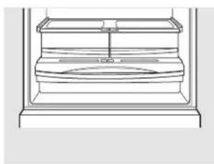
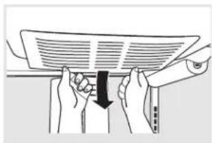
Pure technical line drawing of a mechanical assembly with no text or symbolsAbout the freezer.
Not all features are on all models.
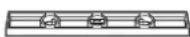
text_image
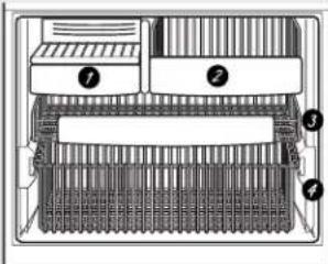
Technical diagram of a multi-chamber air vent system with labeled componentsAppearance and features may vary
Freezer Shelves and Baskets
① A shelf above the ice storage bin
② A half-width basket
3 A shallow full-width basket
4 A deep full-width basket
natural_image
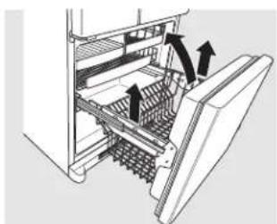
Diagram of a refrigerator interior showing internal compartments and a door handle (no text or symbols)Appearance may vary
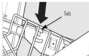
text_image
Tab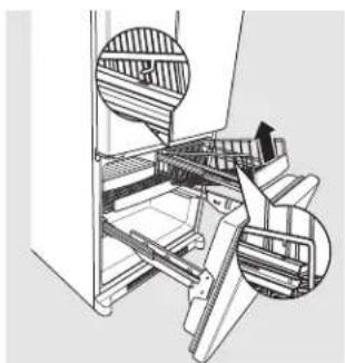
natural_image
Technical illustration of a mechanical assembly with internal components and a magnified inset showing layered structure (no text or symbols)Appearance may vary
natural_image
Diagram of a refrigerator interior showing drawer, shelves, and door (no text or symbols)Appearance may vary
Basket Removal
To remove the deep full-width basket on freezer drawer models:
⑦ Open the freezer drawer until it stops.
2 The freezer basket rests on the inside tabs on the drawer slides.
3 Lift the basket so that all 4 tabs are out of the slide bracket.
4 Tilt the basket and lift out of the drawer.
⑤ Make sure the plastic sleeves remain attached to the 4 tabs on the slide brackets.
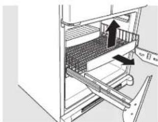
To remove the half-width basket:
⑦ Pull the basket out to the stop location.
2 Lift the basket up at the front to release it from the slides.
3 Lift the back up and out of the slide.
To remove the shallow full-width basket:
7 Pull the basket out to the stop location.
2 Lift the front up and over the stop location.
When replacing the deep full-width basket:
Tilt the basket back and lower it down into the drawer. Rotate the basket to a horizontal position and press it down into the 4 alignment tabs.
NOTE: Always be sure that all 4 basket tabs are engaged in the slide brackets before sliding back into the freezer.
When replacing the basket, make sure that the wire tabs and wire hooks on the sides of the basket go into the slots in the top of the upper basket slides.
NOTE: Always be sure to fully close this basket.
3 Lift the basket up and out.
A newly installed refrigerator may take 12 to 24 hours to begin making ice.
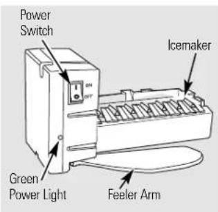
text_image
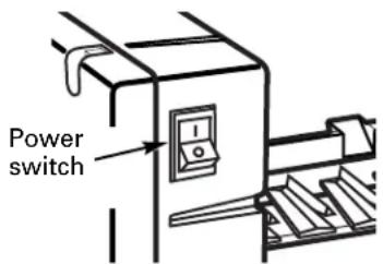
Power Switch Green Power Light Feeler Arm IcemakerAutomatic Icemaker (on some models)
The icemaker will produce seven cubes per cycle—approximately 100–130 cubes in a 24-hour period, depending on freezer compartment temperature, room temperature, number of door openings and other use conditions.
See below for how to access ice and reach the power switch.
If the refrigerator is operated before the water connection is made to the icemaker, set the power switch in the 0 (off) position.
When the refrigerator has been connected to the water supply, set the power switch to the I(on) position. The icemaker power light will turn green when the freezer light switch is pressed in or when the freezer door is closed.
The icemaker will fill with water when it cools to 15^ F ( -10^ C). A newly installed refrigerator may take 12 to 24 hours to begin making ice cubes.
You will hear a buzzing sound each time the icemaker fills with water.
Throw away the first few batches of ice to allow the water line to clear.
Be sure nothing interferes with the sweep of the feeler arm.
When the bin fills to the level of the feeler arm, the icemaker will stop producing ice. It is normal for several cubes to be joined together.
If ice is not used frequently, old ice cubes will become cloudy, taste stale and shrink.
NOTE: In homes with lower-than-average water pressure, you may hear the icemaker cycle multiple times when making one batch of ice.
NOTE: Set the power switch to the 0 (off) position if the water supply is shut off.
text_image
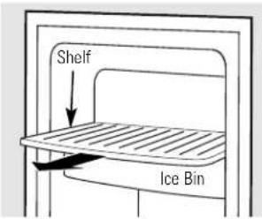
Shelf Ice BinTo reach the power switch.
Accessing Ice and Reaching the Power Switch
To reach the icemaker power switch, pull the shelf above the ice bin straight out. Always be sure to replace the shelf.
To access ice, simply pull the bin forward.
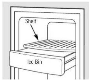
text_image
Shelf Ice BinTo access ice.
Icemaker Accessory Kit
If your refrigerator did not come already equipped with an automatic icemaker, an icemaker accessory kit is available at extra cost.
Check the back of the refrigerator for the specific icemaker kit needed for your model.
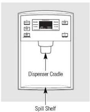
text_image
Dispenser Cradle Spill ShelfTo Use the Dispenser
Press the glass gently against the top of the dispenser cradle.
The spill shelf is not self-draining. To reduce water spotting, the shelf should be cleaned regularly.
Locking the Dispenser
Press the LOCK pad for 3 seconds to lock the dispenser and control panel. To unlock, press and hold the pad again for 3 seconds.
Door Alarm
If no water is dispensed when the refrigerator is first installed, there may be air in the water line system. To set the alarm, press the DOOR ALARM Press the dispenser arm for at least two minutes to pad. The indicator light will illuminate. remove trapped air from the water line and to fill this alarm will sound if either door is water system. To flush out impurities in the water open for more than 2 minutes. The line, throw away the first six glassfuls of water. beeping stops when you close the door.
Care and cleaning of the refrigerator.
Cleaning the Outside
The door handles and trim. Clean with a cloth dampened with soapy water. Dry with a soft cloth. Do not use wax on the door handles and trim.
Keep the outside clean. Wipe with a clean cloth lightly dampened with kitchen appliance wax or mild liquid dish detergent. Dry and polish with a clean, soft cloth.
Do not wipe the refrigerator with a soiled dish cloth or wet towel. These may leave a residue that can erode the paint. Do not use scouring pads, powdered cleaners, bleach or cleaners containing bleach because these products can scratch and weaken the paint finish.
The stainless steel panels and door handles.
Stainless steel (on some models) can be cleaned with a commercially available stainless steel cleaner. A spray-on stainless steel cleaner works best.
Do not use appliance wax or polish on the stainless steel.
Silver-plated plastic parts. Wash parts with soap or other mild detergents. Wipe clean with a sponge, damp cloth or paper towel.
Do not scrub with steel-wool pads or other abrasive cleaners.
Cleaning the Inside
To help prevent odors, leave an open box of baking soda in the refrigerator and freezer compartments.
Unplug the refrigerator before cleaning. If this is not practical, wring excess moisture out of sponge or cloth when cleaning around switches, lights or controls.
Use an appliance wax polish on the inside surface between the doors.
Use warm water and baking soda solution—about a tablespoon (15 ml) of baking soda to a quart (1 liter) of water. This both cleans and neutralizes odors. Rinse and wipe dry.
After cleaning the door gaskets, apply a thin layer of petroleum jelly to the door gaskets at the hinge side. This helps keep the gaskets from sticking and bending out of shape.
Avoid cleaning cold glass shelves with hot water because the extreme temperature difference may cause them to break. Handle glass shelves carefully. Bumping tempered glass can cause it to shatter.
Do not wash any plastic refrigerator parts in the dishwasher.
Silver-accented plastic parts. Wash parts with soapy water. Wipe clean with a sponge, damp cloth or paper towel.
Do not scrub with steel-wool pads or other abrasive cleaners.
Behind the Refrigerator
Be careful when moving the refrigerator away from the wall. All types of floor coverings can be damaged, particularly cushioned coverings and those with embossed surfaces.
Raise the leveling legs located at the bottom front of the refrigerator.
Pull the refrigerator straight out and return it to position by pushing it straight in.
Moving the refrigerator in a side direction may result in damage to the floor covering or refrigerator.
Lower the leveling legs until they touch the floor.
When pushing the refrigerator back, make sure you don't roll over the power cord or icemaker supply line (on some models) and ensure the anti-tip bracket is engaged (if equipped).
Preparing for Vacation
For long vacations or absences, remove food and unplug the refrigerator. Clean the interior with a baking soda solution of one tablespoon (15 ml) of baking soda to one quart (1 liter) of water. Leave the doors open.
Set the icemaker power switch to the 0 (off) position and shut off the water supply to the refrigerator.
If the temperature can drop below freezing, have a qualified servicer drain the water supply system (on some models) to prevent serious property damage due to flooding.
Preparing to Move
Secure all loose items such as base grille, shelves and drawers by taping them securely in place to prevent damage.
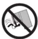
When using a hand truck to move the refrigerator, do not rest the front or back of the refrigerator against the hand truck. This could damage the refrigerator. Handle only from the sides of the refrigerator.
Be sure the refrigerator stays in an upright position during moving.
Replacing the light bulbs.
Turning the control to the 0 (off) position does not remove power to the light circuit.
natural_image
Illustration of hands holding a fan or tablet device with a downward arrow indicating compression (no text or symbols present)Refrigerator Lights
CAUTION: Light bulbs may be hot.
1 Unplug the refrigerator.
2 To remove the light shield, grasp the shield at the back and pull out to release the tabs at the back.
3 Rotate the shield down and then forward to release the tabs at the front of the shield.
4 After replacing with an appliance bulb of the same or lower wattage, replace the shield.
5 Plug the refrigerator back in.
NOTE: Appliance bulbs may be ordered from GE Parts and Accessories, 800.626.2002.
natural_image
Hand holding a kitchen appliance with a black arrow indicating force (no text or symbols)Appearance may vary
Freezer Light
CAUTION: Light bulbs may be hot.
① Unplug the refrigerator.
2 The bulb is located at the top of the freezer inside a light shield. To remove the shield, grasp the shield at the back and pull out to release the tabs at the back.
3 Rotate the shield down and then forward to release the tabs at the front of the shield.
4 After replacing with an appliance bulb of the same or lower wattage, replace the shield.
5 Plug the refrigerator back in.
Trim kits and decorator panels.
For panel required models
Read these instructions completely and carefully.

Before You Begin
Some models are equipped with trim kits that allow you to install door panels. You can order pre-cut black or white decorator panels from GE Parts and Accessories, 800.626.2002, or you can add wood panels to match your kitchen cabinets.
Panels less than 1/4" (6 mm) thick
When installing wood panels less than 1/4" (6 mm) thick, you need to create a filler panel, such as 1/8" cardboard, that will fit between the face of the door and the wood panel. If you are installing the pre-cut decorator panels, pre-cut filler panels are included in the kit. The combined thickness of the decorator or wood panel and the filler panel should be 11/32" (8.7 mm) with the panel itself being no larger than 1/4" (6 mm).
Panels 1/4" thick or less
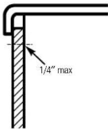
text_image
1/4" maxThe handle and the top and bottom trim stand in front of the surface of the door, which requires that the filler be smaller in length and width than the panel. Use the guidelines below and tape the filler onto the back of the panel.
Trim kits and decorator panels.
3/4" (19 mm) or Raised Panel
A raised panel design screwed or glued to a 1/4" (6 mm) thick backing, or a 3/4" (19 mm) routed board can be used. The raised portion of the panel must be fabricated to permit clearances of at least 2" (5.1 cm) from the handle side for fingertip clearance.
Panels thicker than 1/4" (6 mm), up to 3/4" (19 mm) max., will require that the outer 5/16" (8 mm) of panel perimeter be no thicker than 1/4" (6 mm).
Weight limitations for custom panels:
Fresh Food 10 lbs. (4.5 kg) max. for each door
Freezer Door 18 lbs. (8 kg) max.
Panels thicker than 1/4" (6 mm)

text_image
5/16" (8 mm) 1/4" (6 mm) max 3/4" (19 mm)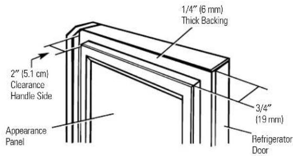
text_image
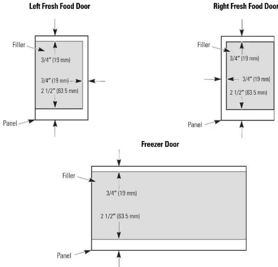
1/4" (6 mm) Thick Backing 2" (5.1 cm) Clearance Handle Side Appearance Panel 3/4" (19 mm) Refrigerator DoorDimensions for Custom Wood Panels
text_image
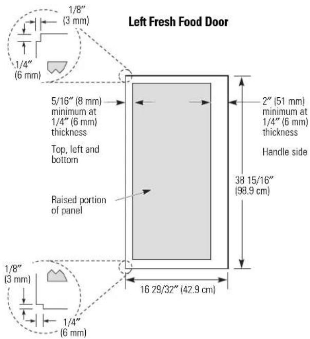
Left Fresh Food Door 1/8" (3 mm) 1/4" (6 mm) 5/16" (8 mm) minimum at 1/4" (6 mm) thickness Top, left and bottom Raised portion of panel 2" (51 mm) minimum at 1/4" (6 mm) thickness Handle side 38 15/16" (98.9 cm) 16 29/32" (42.9 cm) 1/8" (3 mm) 1/4" (6 mm)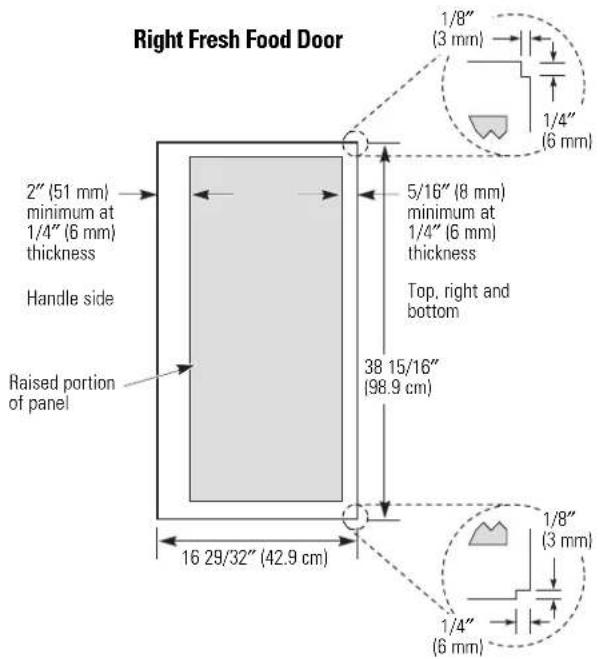
text_image
Right Fresh Food Door 2" (51 mm) minimum at 1/4" (6 mm) thickness Handle side Raised portion of panel 16 29/32" (42.9 cm) 5/16" (8 mm) minimum at 1/4" (6 mm) thickness Top, right and bottom 38 15/16" (98.9 cm) 1/8" (3 mm) 1/4" (6 mm) 1/8" (3 mm) 1/4" (6 mm)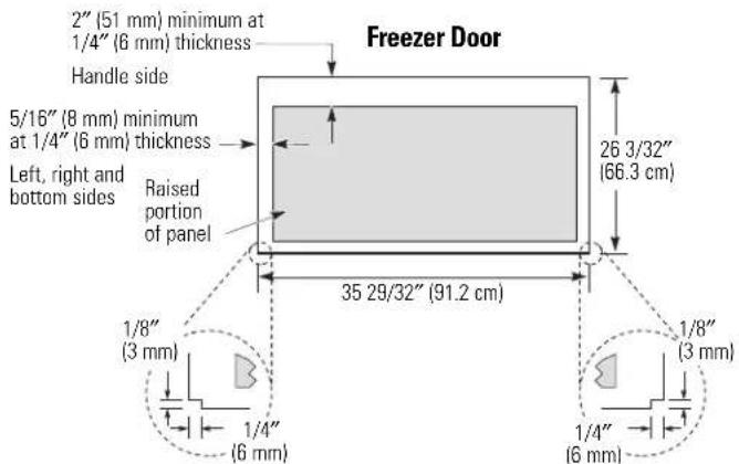
text_image
2" (51 mm) minimum at 1/4" (6 mm) thickness Handle side 5/16" (8 mm) minimum at 1/4" (6 mm) thickness Left, right and bottom sides Raised portion of panel Freezer Door 26 3/32" (66.3 cm) 35 29/32" (91.2 cm) 1/8" (3 mm) 1/4" (6 mm) 1/8" (3 mm) 1/4" (6 mm)Installation Instructions
Refrigerator
Models 21 and 25
Questions? Call 800.GE.CARES (800.432.2737) or Visit our Website at: ge.com In Canada, call 1.800.561.3344 or Visit our Website at: www.geappliances.ca
BEFORE YOU BEGIN
Read these instructions completely and carefully.
- IMPORTANT — Save these instructions for local inspector's use.
- IMPORTANT — Observe all governing codes and ordinances.
- Note to Installer – Be sure to leave these instructions with the Consumer.
- Note to Consumer – Keep these instructions for future reference.
- Skill level – Installation of this appliance requires basic mechanical skills.
- Completion time – Refrigerator Installation 20 minutes
Water Line Installation 30 minutes
Anti-Tip Bracket Installation 20 minutes - Proper installation is the responsibility of the installer.
- Product failure due to improper installation is not covered under the Warranty.
PREPARATION
MOVING THE REFRIGERATOR INDOORS
If the refrigerator will not fit through a doorway, the refrigerator door and freezer drawer can be removed.
- To remove the refrigerator door, see Step 1 in the Reversing the Door Swing section.
- To remove the freezer drawer, see the Removing the Freezer Drawer section.
WATER SUPPLY TO THE ICEMAKER AND DISPENSER (ON SOME MODELS)
If the refrigerator has an icemaker, it will have to be connected to a cold water line. A GE water supply kit (containing tubing, shutoff valve, fittings and instructions) is available at extra cost from your dealer, by visiting our Website at ge.com (in Canada at www.geappliances.ca) or from Parts and Accessories, 800.626.2002 (In Canada 1.888.261.3055).
MATERIALS YOU MAY NEED (not included)
Lag Bolts
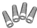
Anchor Sleeves
Drill Bit Appropriate for Anchors
For Anti-Tip Bracket Mounted on CONCRETE Floors Only
TOOLS YOU MAY NEED
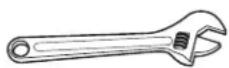
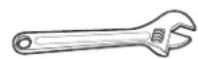
Adjustable Wrench
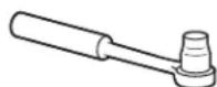
3/8" and 5/16" Socket Ratchet/Driver


1/4" Outer Diameter Compression Nut and Ferrule (sleeve) (icemaker models only)
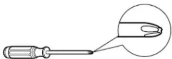
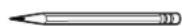
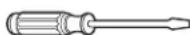
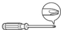
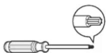
natural_image
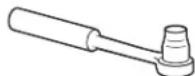
Line drawing of a screwdriver with a magnified close-up view of the tip (no text or symbols)Phillips Head Screwdriver
3/32", 1/8" and 1/4" Allen wrenches
1/8" Drill Bit and Electric or Hand Drill
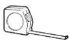
Tape measure
Pencil
1/4" Nut Driver
Wire Cutters
Level
INSTALLING THE ANTI-TIP FLOOR BRACKET (on 21 ft. models)
WARNING
Under certain circumstances, this refrigerator can tip forward.
Injury to persons can result.
Install Anti-Tip Bracket packed with this refrigerator.
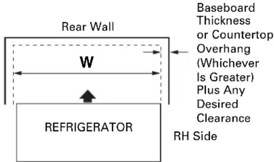
① MEASURE CABINET OPENING AVAILABLE VS. REFRIGERATOR WIDTH
Measure width of cabinet opening where refrigerator will be placed, W.
Be sure to account for any countertop overhang, baseboard thickness and any clearance desired. Width, W, should not be less than 36 inches. The refrigerator will be placed approximately in the middle of this opening.
text_image
Rear Wall W REFRIGERATOR Baseboard Thickness or Countertop Overhang (Whichever Is Greater) Plus Any Desired Clearance RH SideFront
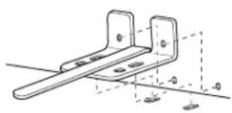
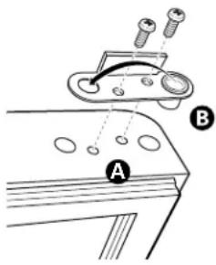
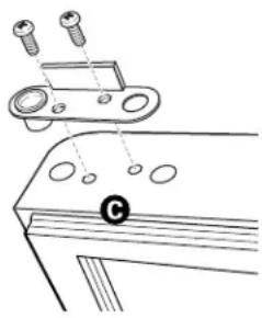
② LOCATING THE ANTI-TIP FLOOR BRACKET
A Place the anti-tip floor bracket locator template (included inside the anti-tip kit) onto the floor up against the rear wall, within W, and in line with the desired location of the RH side of the refrigerator (see Figure 1).
Figure 1 – Installation Overview
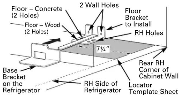
text_image
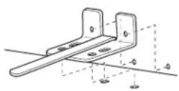
Floor - Concrete (2 Holes) Floor - Wood (2 Holes) 2 Wall Holes Floor Bracket to Install RH Holes 7¼" Rear RH Corner of Cabinet Wall Base Bracket on the Refrigerator RH Side of Refrigerator Locator Template SheetB Place the anti-tip floor bracket onto the locator template with its RH floor holes lined up with the floor holes indicated on the template sheet, approximately 714 " from the edge of the sheet or the RH side of the refrigerator.
C Hold down in position and use the anti-tip floor bracket as a template for marking the holes based upon your configuration and type of construction as shown in Step 3. Mark the hole locations with a pencil, nail or awl.
NOTE:
- It is REQUIRED to use at least 2 screws to mount the floor bracket (one on each side of the anti-tip floor bracket). Both must be into either the wall or the floor. Figure 2 indicates all the acceptable mounting configurations for screws. Identify the screw holes on the anti-tip floor bracket for your configuration.
② LOCATING THE ANTI-TIP FLOOR BRACKET (cont.)
Figure 2 – Acceptable Screw Placement Locations
Preferred Installation – Wood
Preferred Installation – Concrete
Minimum Acceptable #1 – Wall Plate Stud
Minimum Acceptable #2 – Wood Floor
Minimum Acceptable #3 – Concrete Floor
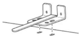
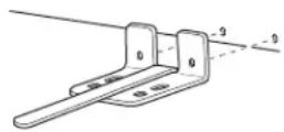
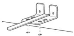
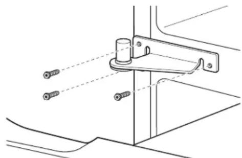
③ ANTI-TIP BRACKET INSTALLATION
A WOOD Wall and Floor Construction:
- Drill the appropriate number of 1/8" pilot holes in the center of each floor bracket hole being used (a nail or awl may be used if a drill is not available) AND remove the locator template from the floor.
- Mount the anti-tip floor bracket by fastening the 2, or preferably 4, #10-16 hex-head screws tightly into place as illustrated in Figure 3.
Figure 3 – Attachment to Wall and Floor
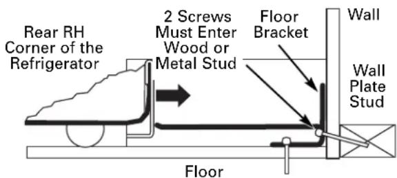
text_image
Rear RH Corner of the Refrigerator 2 Screws Must Enter Wood or Metal Stud Floor Bracket Wall Wall Plate Stud FloorB CONCRETE Wall and Floor Construction:
- Anchors required (not provided): 4 each 1/4'' x 1 1/2'' lag bolts 4 each 1/2'' O.D. sleeve anchors
- Drill the recommended size holes for the anchors into the concrete at the center of the holes marked in Step 2.
- Install the sleeve anchors into the drilled holes. Place the anti-tip floor bracket as indicated in Step 2. Remove the locator template from the floor.
• Install the lag bolts through the anti-tip floor bracket and tighten appropriately.
C WOOD Wall and TILE Floor Construction:
- For this special case, locate the 2 wall holes identified in Fig. 1. Drill an angled 1/8'' pilot hole (approx. as shown in Fig. 3) in the center of each hole.
- Mount the anti-tip floor bracket using the Minimum Acceptable Installation #1, as illustrated in Fig. 2.
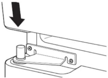
4 POSITIONING THE REFRIGERATOR TO ENGAGE THE ANTI-TIP FLOOR AND BASE BRACKETS
A Before pushing the refrigerator into the opening, plug the power cord into the receptacle and connect waterline (if equipped). Check for leaks.
B Locate the refrigerator's RH side and move back approximately in line with the RH side of the cabinet opening, W. This should position the anti-tip floor bracket to engage the anti-tip base bracket on the refrigerator.
C Gently roll the refrigerator back into the cabinet opening until it comes to a complete stop. Check to see if the refrigerator front lines up with the cabinet front face. If not, carefully rock the refrigerator forward and backward until engagement occurs and you notice that the refrigerator is fully pushed up against the rear wall.
☐ OPTIONAL: Adjust the rear (and front) wheel height settings to fully engage the rear anti-tip brackets, while also aligning the refrigerator front with the cabinet front face.
NOTE:
If you pull the refrigerator out and away from the wall for any reason, make sure the anti-tip floor bracket is engaged when the refrigerator is pushed back against the rear wall.
INSTALLING THE REFRIGERATOR
REFRIGERATOR LOCATION
- Do not install the refrigerator where the temperature will go below 60°F (16°C) because it will not run often enough to maintain proper temperatures.
- Do not install the refrigerator where the temperature will go above 100^ (37°C) because it will not perform properly.
• Install it on a floor strong enough to support it fully loaded.
CLEARANCES
Allow the following clearances for ease of installation, proper air circulation and plumbing and electrical connections.
Standard Depth Counter Depth Models Models
| Sides | 1/8" (3 mm) | 1/8" (3 mm) |
| Top | 1" (25 mm) | 1" (25 mm) |
| Back | 1" (25 mm) | 1/2" (13 mm) |
REMOVE TOP CAP (on some models)
- IMPORTANT NOTE: This refrigerator is 34-1/2" deep. Doors and passageways leading to the installation location must be at least 36" wide in order to leave the doors and handles attached to the refrigerator while transporting it into the installation location. If passageways are less than 36", the refrigerator doors and handles can easily be scratched and damaged. The top cap and doors can be removed to allow the refrigerator to be safely moved indoors. Start with Step A.
- If it is not necessary to remove doors, skip Step A. Leave tape and all packaging on doors until the refrigerator is in the final location.
- SKID REMOVAL: Tilt refrigerator to each side to remove skid.
- NOTE: Use a padded hand truck to move this refrigerator. Place the refrigerator on the hand truck with a side against the truck. We strongly recommend that TWO PEOPLE move and complete this installation.
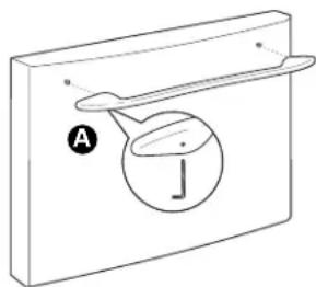
A Locate and remove the two Phillips head screws on the top of the refrigerator. Remove the two screws on each side at the rear of the top cap. Lift off and remove top cap.
B Remove the fresh-food door. Refer to Steps 1 through 3 of "Reversing the Door Swing" section.
C Remove the bottom freezer drawer. Refer to "Removing Freezer Drawer" section.
D Move refrigerator to the installation location.
REMOVE TOP CAP (cont.) (on some models)
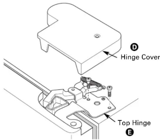
REINSTALL DOORS, DRAWERS AND TOP CAP
E Carefully lower the door onto the center hinge. Reinstall top hinge. NOTE: Ensure the door is properly aligned to the case top to avoid readjustment of the door during top cap reinstallation.
F Place cap over the top of the refrigerator. Reinstall the original screws in the top and back of the cap.
G Reinstall the bottom freezer drawer. Refer to "Replacing the Freezer Drawer" section.
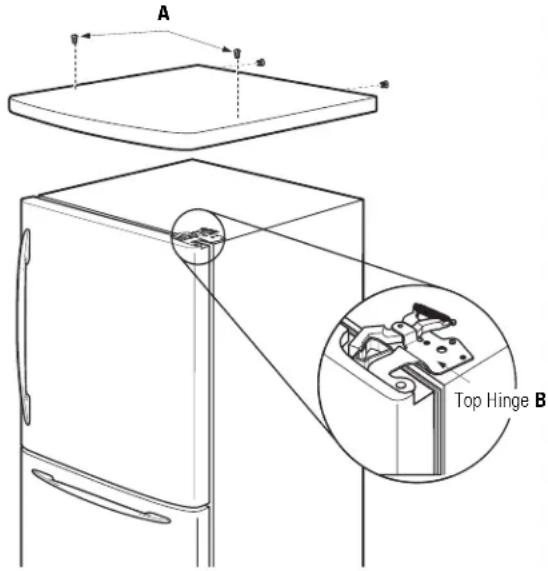
text_image
A Top Hinge B① CONNECTING THE REFRIGERATOR TO THE HOUSE WATER LINE
(icemaker and dispenser models)
A cold water supply is required for automatic icemaker operation. If there is not a cold water supply, you will need to provide one. See Installing the Water Line section.
NOTES:
- Before making the connection to the refrigerator, be sure the refrigerator power cord is not plugged into the wall outlet.
- If your refrigerator does not have a water filter, we recommend installing one if your water supply has sand or particles that could clog the screen of the refrigerator's water valve. Install it in the water line near the refrigerator. If using GE SmartConnect™ Refrigerator Tubing Kit, you will need an additional tube (WX08X10002) to connect the filter. Do not cut plastic tube to install filter.
① CONNECTING THE REFRIGERATOR TO THE HOUSE WATER LINE (cont.)
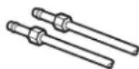
A If you are using copper tubing, place a compression nut and ferrule (sleeve) onto the end of the tubing coming from the house cold water supply.
If you are using the GE SmartConnect™ tubing, the nuts are already assembled to the tubing.
B If you are using copper tubing, insert the end of the tubing into the refrigerator connection, at the back of the refrigerator, as far as possible. While holding the tubing, tighten the fitting.
If you are using GE SmartConnect™ tubing, insert the molded end of the tubing into the refrigerator connection, at the back of the refrigerator, and tighten the compression nut until it is hand tight. Then tighten one additional turn with a wrench. Overtightening may cause leaks.
C Fasten the tubing into the clamp provided to hold it in position. You may need to pry open the clamp.
One of the illustrations below will look like the connection on your refrigerator.
Icemaker-Ready models
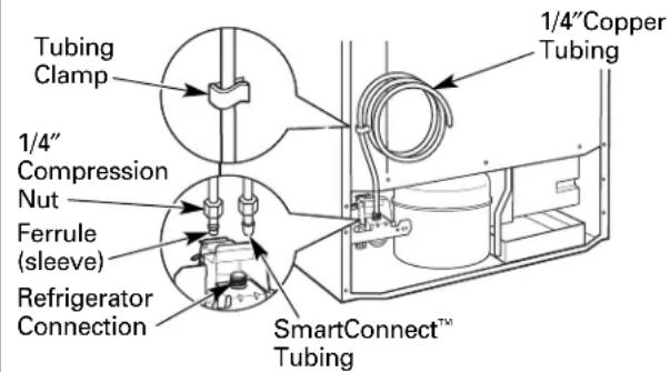
text_image
Tubing Clamp 1/4" Compression Nut Ferrule (sleeve) Refrigerator Connection 1/4"Copper Tubing SmartConnect™ TubingIcemaker-Installed Models
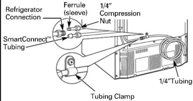
text_image
Refrigerator Connection Ferrule (sleeve) 1/4" Compression Nut SmartConnect™ Tubing 1/4"Tubing Tubing Clamp② TURN ON THE WATER SUPPLY (icemaker and dispenser models)
Turn the water on at the shutoff valve (house water supply) and check for any leaks.
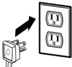
③ PLUG IN THE REFRIGERATOR
On models with an icemaker, before plugging in the refrigerator, make sure the icemaker power switch is set to the O (off) position.
text_image
Diagram showing a plug inserted into an electrical socket with two I/O switches, indicating internal resistance or power flow.See the grounding information attached to the power cord.
4 PUT THE REFRIGERATOR IN PLACE
Move the refrigerator to its final location. Make sure the back side of the refrigerator engages the anti-tip bracket properly. The anti-tip floor bracket should line up with the cutout in the back bottom of the refrigerator, and fit through the cutout when the refrigerator is pushed into position. (Refer to page 18, Step 2A for more information.)
Turn the front roller adjusting screws clockwise to raise the refrigerator, counterclockwise to lower it. Use a 3/8"hex wrench with extension, or an adjustable wrench.
natural_image
Mechanical assembly diagram showing components with arrows indicating motion (no text or labels)Roller adjusting screws
To adjust the rollers on 21' Counter Depth models:
These models also have rear adjustable rollers so you can align the refrigerator with your kitchen cabinets. Use a 3/8"hex wrench with extension to turn the screws for the rear rollers—clockwise to raise the refrigerator, counterclockwise to lower it.
INSTALLING THE REFRIGERATOR (cont.)
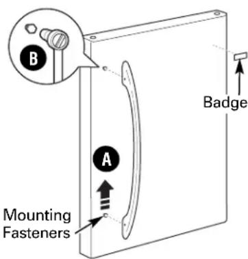
6 REMOVE THE FRESH FOOD DOOR HANDLE
(For placement in the installation location or reversal of the handles – on some models)
Stainless steel (on some models):
A REMOVING THE DOOR HANDLE: Loosen the set screws with the 3/32" Allen wrench and remove the handle. NOTE: For Double Door models follow the same procedure on the opposite door.
text_image
A B Mounting Fasteners Badge(appearance may vary)
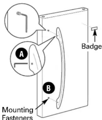
Plastic handle (on some models):
A REMOVING THE DOOR HANDLE: Depress the tab on the underside of the handle and slide the handle up and off of the mounting fasteners.
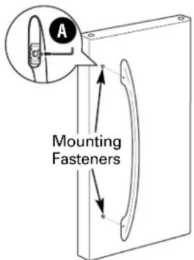
B REVERSING THE DOOR HANDLE (on some models):
- Remove the handle mounting fasteners with a 1/4"Allen wrench and transfer the handle mounting fasteners to the right side.
- Remove the logo badge.
- Remove and transfer the plug button to the left side of the fresh food door. NOTE: Use a flat plastic edge to prevent damaging the door. Remove any adhesive on the door with a mild detergent. Remove the paper covering on the adhesive backing on the logo badge prior to carefully attaching the badge to the door.
text_image
B A Mounting Fasteners Badge(appearance may vary)
⑦ REMOVE THE FREEZER DOOR HANDLE
Stainless steel and plastic handles:
A Loosen the set screws located on the underside of the handle with the 1/8"Allen wrench and remove the handle.
NOTE: If the handle mounting fasteners need to be tightened or removed use a 1/4"Allen wrench.
natural_image
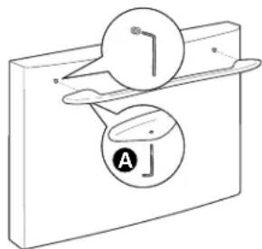
Simple line drawing of a mechanical component with a circular component and a labeled section (no text or symbols)8 ATTACH THE FRESH FOOD DOOR HANDLE
Stainless steel handle:
A Attach the handle to the handle mounting fasteners and tighten the set screws with a 3/32"Allen wrench.
NOTE: For Double Door models follow the same procedure on the opposite door.
text_image
Mounting Fasteners(appearance may vary)
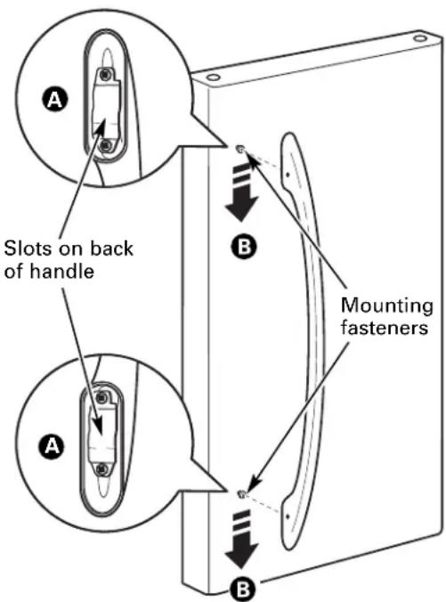
Plastic handle:
A Attach the handle to the handle mounting fasteners by aligning the slots with the handle mounting fasteners.
B Slide it down until it is firmly locked into position.
text_image
Slots on back of handle Mounting fasteners(appearance may vary)
⑨ ATTACH THE FREEZER DOOR HANDLE
Stainless steel and plastic handles:
Attach the handle firmly to the mounting fasteners and tighten the set screws on the bottom of the handle with a 1/8"Allen wrench.
text_image
A J(appearance may vary)
INSTALLING THE REFRIGERATOR (cont.)
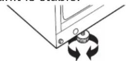
10 LEVEL THE REFRIGERATOR
The leveling legs have 2 purposes:
1) Leveling legs adjust so the refrigerator is firmly positioned on the floor and does not wobble.
2) Leveling legs serve as a stabilizing brake to hold the refrigerator securely in position during operation and cleaning. The leveling legs also prevent the refrigerator from tipping.
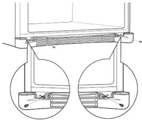
A Remove the grille by removing the two Phillips head screws.
natural_image
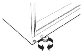
Technical line drawing of a mechanical assembly with two circular insets showing internal components (no text or symbols)B Turn the leveling legs clockwise to raise the refrigerator, counterclockwise to lower it.
natural_image
Pure technical diagram of a mechanical bracket with two circular arrows indicating rotation or force application (no text or symbols)CAUTION: To avoid possible personal injury or property damage, the leveling legs must be firmly touching the floor.
C Replace the base grille by inserting the two Phillips head screws.
11 SET THE CONTROLS
Set the controls to the recommended setting.
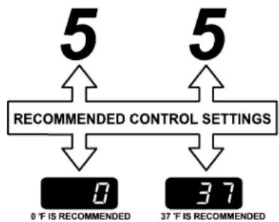
flowchart
graph TD
    A["5"] --> B["RECOMMENDED CONTROL SETTINGS"]
    C["5"] --> D["RECOMMENDED CONTROL SETTINGS"]
    B --> E["0"]
    D --> F["37"]
    E --> G["0 °F IS RECOMMENDED"]
    F --> H["37 °F IS RECOMMENDED"]
12 REMOVE PACKAGING START ICEMAKER
(icemaker models)
A) Remove all tape, foam and protective packing from shelves and drawers.
B) Remove the tie downs from the freezer baskets.
C) Place half width basket onto drawer slides. See About the freezer section for instructions.
Set the icemaker power switch to the I (on) position. The icemaker will not begin to operate until it reaches its operating temperature of 15^ F ( -9^ C) or below. It will then begin operation automatically. It will take 2–3 days to fill the ice bin.
text_image
Power switchNOTE:
In lower water pressure conditions, the water valve may turn on up to 3 times to deliver enough water to the icemaker.
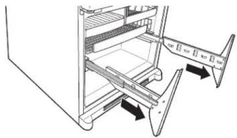
REMOVING THE FREEZER DRAWER (on some models)
The freezer drawer can be removed, if needed, to fit through tight areas.
Read these instructions completely and carefully.
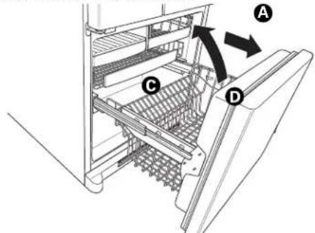
① REMOVE THE BASKET
A Open the freezer drawer until it stops.
B Cut the 2 wire ties off of the basket with wire cutters.
C The freezer basket rests inside 4 tabs on the freezer slides. Lift the basket up and out of the 4 tabs.
D Tilt the front up and lift the entire basket up and out of the drawer.
text_image
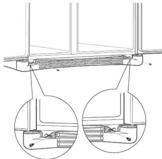
Technical diagram of a refrigerator interior with labeled parts A, B, and C, showing structural components and directional arrows.③ REMOVE THE BASE GRILLE (if needed)
If, after removing the freezer drawer and refrigerator door, the refrigerator will still not fit through a doorway, the base grille can be removed.
A Remove the base grille by removing the 2 Phillips head screws.
natural_image
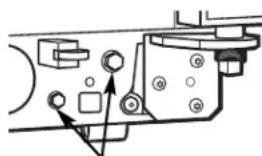
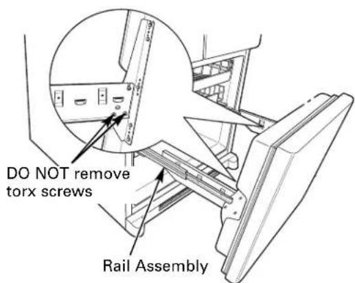
Technical line drawing of a mechanical assembly with two circular insets showing internal components (no text or symbols)② REMOVE THE DRAWER FRONT FROM THE SLIDES
A Remove the 10 hex head screws from the door and remove the door.
DO NOT remove the torx screws from the rail assemblies.
text_image
DO NOT remove torx screws Rail AssemblyB Set the drawer front on a non-scratching surface.
C Push the rail assemblies back into the cabinet.
REPLACING THE FREEZER DRAWER (on some models)
Two people may be required to complete this procedure.
① ATTACH AND SECURE THE DRAWER FRONT TO THE SLIDES
A Pull out the rail assemblies to the full length on each side of the cabinet.
natural_image
Technical line drawing of a refrigerator interior showing door frame and shelf arrangement (no text or symbols)B Drive the top screw into the door on each side until it is 1/2 way in.
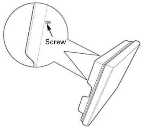
text_image
ScrewC Hang the drawer front onto open slots on the slides.
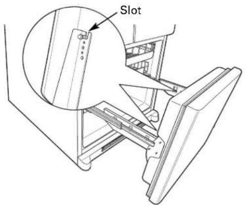
text_image
Slot① ATTACH AND SECURE THE DRAWER FRONT TO THE SLIDES (CONT.)
D Drive screws fully. (There are 10 screws.)
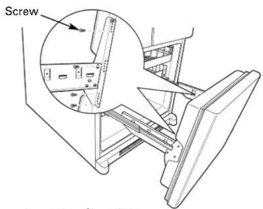
text_image
Screw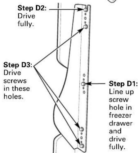
text_image
Step D2: Drive fully. Step D3: Drive screws in these holes. Step D1: Line up screw hole in freezer drawer and drive fully.② REPLACE THE FREEZER BASKET
Replace the lower freezer basket by lowering it into the frame.
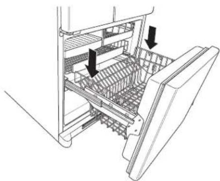
natural_image
Technical line drawing of a refrigerator interior showing internal compartments and structural ribs (no text or symbols)REVERSING THE DOOR SWING (Single Door Refrigerator Models only)
IMPORTANT NOTES
When reversing the door swing:
NOTE: Door swing is not reversible on stainless steel models.
- Read the instructions all the way through before starting.
- Parts are included in the door hinge kit.
- Handle parts carefully to avoid scratching paint.
- Set screws down by their related parts to avoid using them in the wrong places.
- Provide a non-scratching work surface for the doors.
IMPORTANT: Once you begin, do not move the cabinet until door-swing reversal is completed.
These instructions are for changing the hinges from the right side to the left side—if you ever want to change the hinges back to the right side, follow these same instructions and reverse all references to left and right.
- Once door swing is finalized, ensure the logo badge is properly aligned and permanently secured to the door by removing the adhesive cover on the back side.
NOTE: A replacement logo badge is included in the hinge kit.
Unplug the refrigerator from its electrical outlet.
Empty all door shelves, including the dairy compartment.
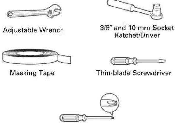
TOOLS YOU WILL NEED
Adjustable Wrench
5/16" Socket Ratchet/Driver
Masking Tape
Thin-blade Screwdriver
Phillips Screwdriver
Torx T-20 Driver
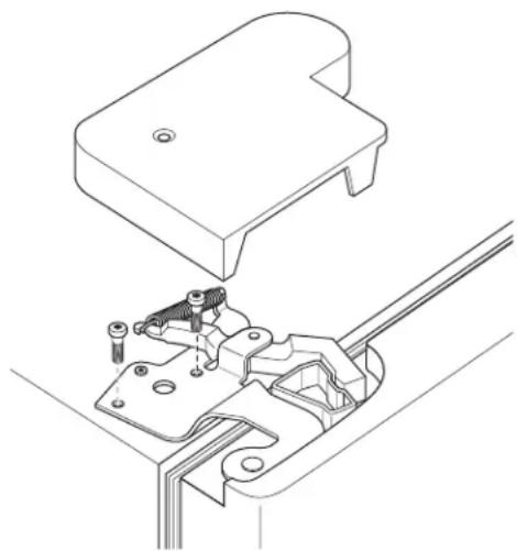
① REMOVE THE REFRIGERATOR DOOR
A Tape the door shut with masking tape.
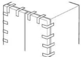
natural_image
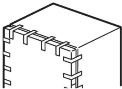
Isometric line drawing of a structural frame with vertical supports and diagonal braces (no text or symbols)B Remove the hinge cover on top of the refrigerator door by removing the Phillips head screws and pulling it up.
C Using a 5/16" socket ratchet/driver, remove the bolts securing the top hinge to the cabinet. Then lift the hinge straight up to free the hinge pin from the socket in the top of the door.

text_image
Hinge Cover Top Hinge B CD Remove the tape and tilt the door away from the cabinet. Lift the door off the center hinge pin. Ensure that the plastic hinge pin thimble remains on the hinge pin or inside door hinge pin hole located in the bottom of the door.
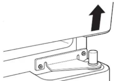
natural_image
Technical line drawing of a mechanical bracket with an upward arrow indicating motion (no text or symbols)E Set the door on a non-scratching surface with the inside up.
REVERSING THE DOOR SWING (cont.)
② REMOVE CENTER HINGE
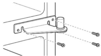
Using a 5/16"socket ratchet/driver, remove the bolts securing the center hinge to the cabinet. Set the hinge and bolts aside.
natural_image
Technical line drawing of a mechanical bracket with screws and a cylindrical component, no text or symbols present③ INSTALL CENTER HINGE
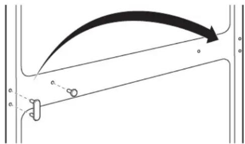
A Transfer the plug button and screw hole cover in the hinge holes on the left side to the right side.
text_image
Diagram showing a curved arrow and labeled points (a, b, c) with directional arrows and dashed lines, likely illustrating a physics or engineering concept.B Install the center hinge from the kit on the left side.
natural_image
Technical line drawing of a mechanical clamp or bracket assembly with screws, no text or symbols presentNOTE: A new hinge will be required for the left side (supplied in the door hinge kit).
4 TRANSFER REFRIGERATOR DOOR STOP
A Remove the door stop on right side of the bottom of the refrigerator door by removing the two screws.
B Move the plastic hinge hole thimble to the opposite hole.
C Install the door stop on the left side, making sure to line up the screw holes in the door stop with the holes in the bottom of the door.
text_image
Technical diagram showing a mechanical component with labeled parts A and B, including bolts and a curved handle.Bottom of Refrigerator Door (Right Side)
natural_image
Technical line drawing of a mechanical assembly with mounting holes and a labeled component (no text or symbols)Bottom of Refrigerator Door (Left Side)
5 TRANSFER REFRIGERATOR DOOR HANDLE TO RIGHT
Refer to Remove the Fresh Food Door Handle and Attach the Fresh Food Door Handle sections for instructions.
6 REHANG REFRIGERATOR DOOR
A Lower the refrigerator door onto the center hinge pin. Ensure that the plastic hinge pin thimble is on the center hinge pin or inside door hinge pin hole located in the bottom of the door.
natural_image
Mechanical assembly diagram showing a lever mechanism with a downward arrow (no text or symbols)B Insert the top hinge pin into the hinge hole on top of the refrigerator door. Make sure the door is aligned with the cabinet.
Attach the hinge to the top of the cabinet loosely with the bolts.
C Make sure the gasket on the door is flush against the cabinet and is not folded. Support the door on the handle side and make sure the door is straight and the gap between the doors is even across the front. While holding the door in place, tighten the top hinge bolts. Replace the hinge cover.
natural_image
Technical line drawing of a mechanical assembly with no visible text or symbols7 INSTALL THE LOGO BADGE
Remove the adhesive backing paper and align the pins on the back of the badge with the holes in the door. Apply pressure to the badge to ensure it sticks to the door.
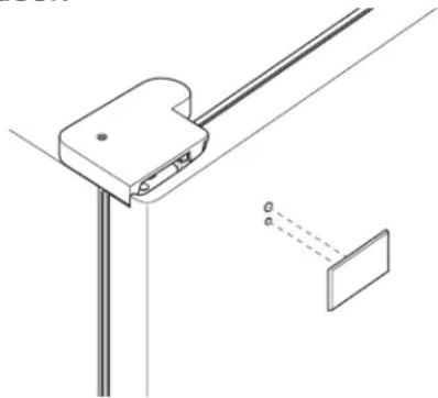
natural_image
Technical line drawing of a mechanical clamp or bracket assembly with a separate inset showing a dashed-line component (no text or symbols)REMOVING THE DOORS (Double Door Refrigerator Models only)
IMPORTANT NOTES
NOTE: Door swing is not reversible.
- Read the instructions all the way through before starting.
- Handle parts carefully to avoid scratching paint.
- Set screws down by their related parts to avoid using them in the wrong places.
- Provide a non-scratching work surface for the doors.
IMPORTANT: Once you begin, do not move the cabinet.
These instructions are for removing the doors.
Unplug the refrigerator from its electrical outlet.
Empty all door shelves, including the dairy compartment.
TOOLS YOU WILL NEED
Phillips Screwdriver
① REMOVE THE REFRIGERATOR DOORS
A Tape the doors shut with masking tape.
natural_image
Pure technical line drawing of a structural joint or connection detail (no text or symbols)(for water dispenser models)
B Start with right-hand door first: Remove the screw securing the center hinge cover, lift the hinge cover and place to the side on top of the refrigerator.
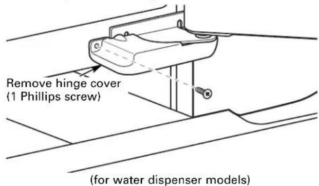
text_image
Remove hinge cover (1 Phillips screw) (for water dispenser models)C Remove water coupling and power coupling.

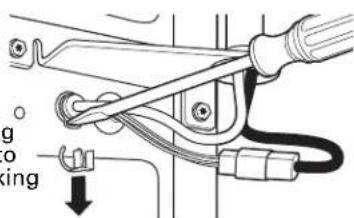
Water Coupling
Remove the metal spring clip. Use a screwdriver to push the red plastic locking clip down and off.
text_image
Technical diagram showing mechanical assembly with labeled parts and directional arrow indicating motion
Water Coupling
Push red collar and hold.
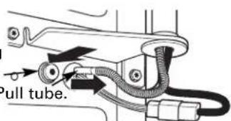
text_image
Pull tube.
Power Coupling
Black mark flush with collar assembly
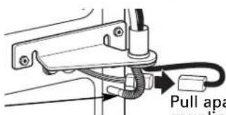
text_image
Pull apa couplingPull apart power coupling to disconnect
① REMOVE THE REFRIGERATOR DOORS (cont.)
☐ Remove the hinge cover on top of the refrigerator door by removing the Phillips head screws and pulling it up.
E Using a 5/16"socket ratchet/driver, remove the bolts securing the top hinge to the cabinet. Then lift the hinge straight up to free the hinge pin from the socket in the top of the door.
text_image
Hinge Cover Top Hinge EF Remove the tape and tilt the door away from the cabinet. Lift the door off the center hinge pin. Ensure that the plastic hinge pin thimble remains on the hinge pin or inside door hinge pin hole located in the bottom of the door.
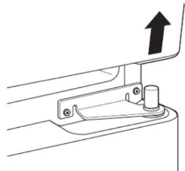
natural_image
Technical line drawing of a mechanical bracket with an upward arrow indicating motion (no text or symbols)G Set the door on a non-scratching surface with the inside up.
② REMOVE CENTER HINGE
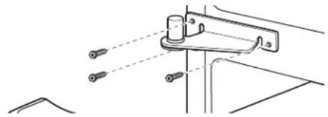
Using a 5/16"socket ratchet/driver, remove the bolts securing the center hinge to the cabinet. Set the hinge and bolts aside.

natural_image
Technical line drawing of a mechanical bracket with mounting holes and a cylindrical component (no text or symbols)③ REMOVE OPPOSITE DOOR
Follow the same procedure on the opposite door. There are no wires, water lines or center hinge covers on the opposite side.
4 REMOVE FREEZER DRAWER
Refer to the Removing the Freezer Drawer section for instructions.
REPLACING THE DOORS (Double Door Refrigerator Models only)
① INSTALL CENTER HINGE
Install the center hinge on each side.
natural_image
Technical line drawing of a mechanical clamp or bracket assembly with two screws (no text or symbols)② REHANG REFRIGERATOR DOORS
A Lower the refrigerator door onto the center hinge pin. Ensure that the plastic hinge pin thimble is on the center hinge pin or inside door hinge pin hole located in the bottom of the door.
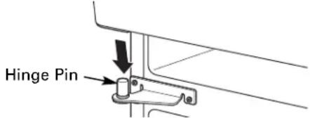
text_image
Hinge PinB Securely tape the door shut with masking tape or have a second person support the door.
C Route wires through bottom right hinge pin slot. Insert the top hinge pin into the hinge hole on top of the refrigerator door. Make sure the door is aligned with the cabinet and opposite door. Attach the hinge to the top of the cabinet loosely with the bolts.
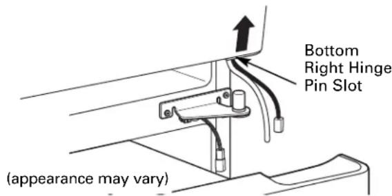
text_image
Bottom Right Hinge Pin Slot (apppearance may vary)D On right-hand doors, pass the wires and water line through the center hinge pin. Then connect the water line and 4-pin connector.
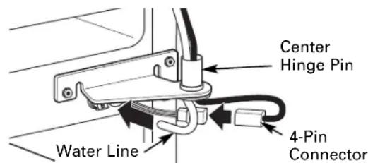
text_image
Water Line Center Hinge Pin 4-Pin Connector② REHANG REFRIGERATOR DOORS (CONT.)
E Make sure the gasket on the door is flush against the cabinet and is not folded. Make sure the door is straight and the gap between the doors is even across the front. While holding the aligned door in place, tighten the top hinge bolts. Replace the hinge cover and screw.
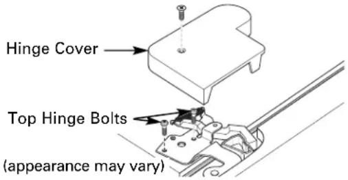
text_image
Hinge Cover Top Hinge Bolts (appearance may vary)③ REPLACE OPPOSITE DOOR
Follow the same procedure on the opposite door. There is no water line or hinge cover.
4 ALIGN DOUBLE DOORS
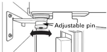
If the top of the doors are uneven, first try to raise the lowest door by turning the leveling leg on the same side as the door until the doors are even. If the unit rocks, re-adjust the leveling legs to the extent that the unit is stable.
If the doors remain uneven, turn the adjustable pin to raise, or lower, the left door to match the right door. Use a 1/4" Allen wrench to turn the pin.
text_image
Adjustable pin⑤ REPLACE FREEZER DRAWER
Refer to the Replacing the Freezer Drawer section for instructions.
INSTALLING THE WATER LINE (ICEMAKER MODELS)
BEFORE YOU BEGIN
Recommended copper water supply kits are WX8X2, WX8X3 or WX8X4, depending on the amount of tubing you need. Approved plastic water supply lines are GE SmartConnect™ Refrigerator Tubing (WX08X10006, WX08X10015 and WX08X10025).
When connecting your refrigerator to a GE Reverse Osmosis Water System, the only approved installation is with a GE RVKit. For other reverse osmosis water systems, follow the manufacturer's recommendations.
If the water supply to the refrigerator is from a Reverse Osmosis Water Filtration System AND the refrigerator also has a water filter, use the refrigerator's filter bypass plug. Using the refrigerator's water filtration cartridge in conjunction with the RO filter can result in hollow ice cubes.
This water line installation is not warranted by the refrigerator or icemaker manufacturer. Follow these instructions carefully to minimize the risk of expensive water damage.
Water hammer (water banging in the pipes) in house plumbing can cause damage to refrigerator parts and lead to water leakage or flooding. Call a qualified plumber to correct water hammer before installing the water supply line to the refrigerator.
To prevent burns and product damage, do not hook up the water line to the hot water line.
If you use your refrigerator before connecting the water line, make sure the icemaker power switch is in the O (off) position.
Do not install the icemaker tubing in areas where temperatures fall below freezing.
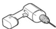
When using any electrical device (such as a power drill) during installation, be sure the device is double insulated or grounded in a manner to prevent the hazard of electric shock, or is battery powered.
All installations must be in accordance with local plumbing code requirements.
WHAT YOU WILL NEED
- Copper or GE SmartConnect™ Refrigerator Tubing kit, 1/4" outer diameter to connect the refrigerator to the water supply. If using copper, be sure both ends of the tubing are cut square.
To determine how much tubing you need: measure the distance from the water valve on the back of the refrigerator to the water supply pipe. Be sure there is sufficient extra tubing to allow the refrigerator to move out from the wall after installation.
GE SmartConnect™ Refrigerator Tubing Kits are available in the following lengths:
6'(1.8 m) - WX08X10006
15'(4.6 m) - WX08X10015
25'(7.6 m) - WX08X10025
INSTALLING THE WATER LINE (CONT.)
WHAT YOU WILL NEED (CONT.)
NOTE: The only GE approved plastic tubing is that supplied in GE SmartConnect™ Refrigerator Tubing kits. Do not use any other plastic water supply line because the line is under pressure at all times. Certain types of plastic will crack or rupture with age and cause water damage to your home.
- A GE water supply kit (containing tubing, shutoff valve and fittings listed below) is available at extra cost from your dealer or from Parts and Accessories, 800.626.2002 (in Canada 1.888.261.3055).
- A cold water supply. The water pressure must be between 20 and 120 p.s.i. (1.4–8.1 bar).
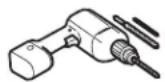
- Power drill.
- 1/2" or adjustable wrench.
- Straight and Phillips blade screwdriver.
- Two 1/4" outer diameter compression nuts and 2 ferrules (sleeves)—to connect the copper tubing to the shutoff valve and the refrigerator water valve. OR
- If you are using a GE SmartConnect™ Refrigerator Tubing kit, the necessary fittings are preassembled to the tubing.
- If your existing copper water line has a flared fitting at the end, you will need an adapter (available at plumbing supply stores) to connect the water line to the refrigerator OR you can cut off the flared fitting with a tube cutter and then use a compression fitting. Do not cut formed end from GE SmartConnect™ Refrigerator tubing.
- Shutoff valve to connect to the cold water line. The shutoff valve should have a water inlet with a minimum inside diameter of 5/32" at the point of connection to the COLD WATER LINE. Saddle-type shutoff valves are included in many water supply kits. Before purchasing, make sure a saddle-type valve complies with your local plumbing codes.
Install the shutoff valve on the nearest frequently used drinking water line.
① SHUT OFF THE MAIN WATER SUPPLY
Turn on the nearest faucet long enough to clear the line of water.
② CHOOSE THE VALVE LOCATION
Choose a location for the valve that is easily accessible. It is best to connect into the side of a vertical water pipe. When it is necessary to connect into a horizontal water pipe, make the connection to the top or side, rather than at the bottom, to avoid drawing off any sediment from the water pipe.
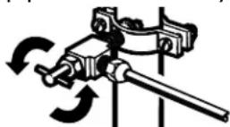
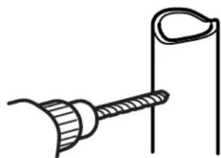
③ DRILL THE HOLE FOR THE VALVE
Drill a 1/4"hole in the water pipe (even if using a self-piercing valve), using a sharp bit. Remove any burrs resulting from drilling the hole in the pipe.
Take care not to allow water to drain into the drill.
Failure to drill a 1/4"hole may result in reduced ice production or smaller cubes.
natural_image
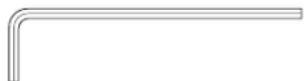
Simple line drawing of a tool or probe with a curved handle and vertical rod (no text or symbols)4 FASTEN THE SHUTOFF VALVE
Fasten the shutoff valve to the cold water pipe with the pipe clamp.
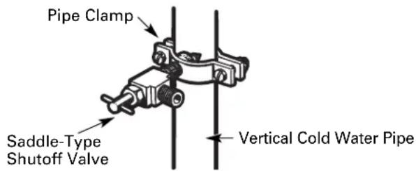
text_image
Pipe Clamp Saddle-Type Shutoff Valve Vertical Cold Water PipeNOTE: Commonwealth of Massachusetts Plumbing Codes 248CMR shall be adhered to. Saddle valves are illegal and use is not permitted in Massachusetts. Consult with your licensed plumber.
⑤ TIGHTEN THE PIPE CLAMP
Tighten the clamp screws until the sealing washer begins to swell.
NOTE: Do not overtighten or you may crush the tubing.
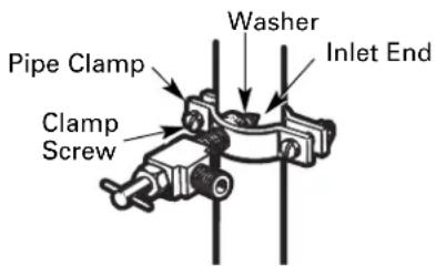
text_image
Pipe Clamp Clamp Screw Washer Inlet End6 ROUTE THE TUBING
Route the tubing between the cold water line and the refrigerator.
Route the tubing through a hole drilled in the wall or floor (behind the refrigerator or adjacent base cabinet) as close to the wall as possible.
7 CONNECT THE TUBING TO THE VALVE
Place the compression nut and ferrule (sleeve) for copper tubing onto the end of the tubing and connect it to the shutoff valve.
Make sure the tubing is fully inserted into the valve. Tighten the compression nut securely.
For plastic tubing from a GE SmartConnect™ Refrigerator Tubing kit, insert the molded end of the tubing into the shutoff valve and tighten compression nut until it is hand tight, then tighten one additional turn with a wrench.
Overtightening may cause leaks.
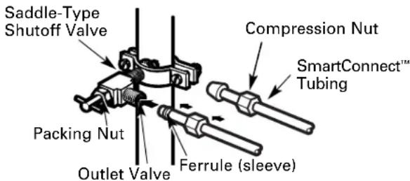
text_image
Saddle-Type Shutoff Valve Packing Nut Outlet Valve Compression Nut SmartConnect™ Tubing Ferrule (sleeve)NOTE: Commonwealth of Massachusetts Plumbing Codes 248CMR shall be adhered to. Saddle valves are illegal and use is not permitted in Massachusetts. Consult with your licensed plumber.
8 FLUSH OUT THE TUBING
Turn the main water supply on and flush out the tubing until the water is clear.
Shut the water off at the water valve after about one quart (1 liter) of water has been flushed through the tubing.
natural_image
Simple line drawing of a flower with a curved arrow, no text or symbols presentTo complete the installation of the refrigerator, go back to Step 1 in Installing the Refrigerator.
Normal operating sounds.

Newer refrigerators sound different from older refrigerators. Modern refrigerators have more features and use newer technology.
Do you hear what I hear? These sounds are normal.
HUMMM... WHOOSH...
The new high efficiency compressor may run faster and longer than your old refrigerator and you may hear a high-pitched hum or pulsating sound while it is operating.
You may hear a whooshing sound when the doors close. This is due to pressure equalizing within the refrigerator.
WHIR!

You may hear the fans spinning at high speeds. This happens when the refrigerator is first plugged in, when the doors are opened frequently or when a large amount of food is added to the refrigerator or freezer compartments. The fans are helping to maintain the correct temperatures.
The fans change speeds in order to provide optimal cooling and energy savings.
CLICKS, POPS, CRACKS and SNAPS
- You may hear cracking or popping sounds when the refrigerator is first plugged in. This happens as the refrigerator cools to the correct temperature.
The freezer control will click when starting or stopping the compressor.
■ Defrost timer snapping in and out of the defrost cycle.
■ Expansion and contraction of cooling coils during and after defrost can cause a cracking or popping sound.
On models with an icemaker, after an icemaking cycle, you may hear the ice cubes dropping into the ice bucket.
On models with a dispenser, during water dispense, you may hear the water lines move at initial dispense and after dispenser button is released.
WATER SOUNDS

The flow of refrigerant through the freezer cooling coils may make a gurgling noise like boiling water.
Water dropping on the defrost heater can cause a sizzling, popping or buzzing sound during the defrost cycle.
A water dripping noise may occur during the defrost cycle as ice melts from the evaporator and flows into the drain pan.
- Closing the door may cause a gurgling sound due to pressure equalization.

For additional information on normal icemaker operating sounds, see the About the automatic icemaker section.
Before you call for service...

Troubleshooting Tips Save time and money! Review the charts on the following pages first and you may not need to call for service.
Problem Possible Causes What To Do
| Refrigerator does not operate | Refrigerator in defrost cycle. | • Wait about 30 minutes for defrost cycle to end. |
| Control in 0 (off) position. | • Move the control to a temperature setting. | |
| Refrigerator is unplugged. | • Push the plug completely into the outlet. | |
| The fuse is blown/circuit breaker is tripped. | • Replace fuse or reset the breaker. | |
| Vibration or rattling (slight vibration is normal) | Leveling legs need adjusting. | • See Level the Refrigerator. |
| Problem Possible Causes What To Do | ||
| Motor operates for long periods or cycles is first on and off frequently. (Modern refrigerators with more storage space and a larger freezer require more operating time. They start and stop often to maintain even temperatures.) | Normal when refrigerator plugged in. cool down. | ·Wait 24 hours for the refrigerator to completely |
| Often occurs when large ·This is normal. amounts of food are placed in refrigerator. | ||
| Door left open. | ·Check to see if package is holding door open. | |
| Hot weather or frequent ·This is normal. door openings. | ||
| Temperature control set at the coldest setting. | ·See About the controls. | |
| TurboCool function has been activated. | ·This is normal when the TurboCool function is activated. See About TurboCool for more information. | |
| Refrigerator or freezer compartment too warm | Temperature controls not set cold enough. | ·See About the controls. |
| Warm weather or frequent door openings. | ·Set the temperature control one step colder. See About the controls. | |
| Door left open. | ·Check to see if package is holding door open. | |
| Frost or ice crystals on frozen food (frost within package is normal) | Door left open. | ·Check to see if package is holding door open. |
| Door openings too frequent or too long. | ||
| Frequent “buzzing” sound | Icemaker power switch is in the l(on) position, but the water supply to the refrigerator has not been connected. | ·Set the power switch to the 0(off) position. Keeping it in the l(on) position will damage the water valve. |
| Small or hollow cubes | Water filter clogged. | ·Replace filter cartridge with new cartridge or with plug. |
| Automatic icemaker (on some models) does not work | Icemaker power switch is not on. | ·Set the power switch to the l(on) position. The icemaker power light will turn green when the freezer light switch is pressed in or when the freezer door is closed. |
| Water supply turned off or not connected. | ·See Installing the water line. | |
| Freezer compartment too warm. | ·Wait 24 hours for the refrigerator to completely cool down. | |
| Piled up cubes in the storage bin cause the icemaker to shut off. | ·Level cubes by hand. | |
| Ice cubes stuck in icemaker. (Green power light on icemaker blinking.) | ·Turn off the icemaker, remove cubes and turn the icemaker back on. | |
| Icemaker light is not lit. | ·This is normal when the freezer door is open. The icemaker power light will turn green when the freezer light switch is pressed in or when the freezer door is closed. | |
Before you call for service...

Troubleshooting Tips
Problem Possible Causes What To Do
| Ice cubes have odor/taste to ice cubes. | Food transmitting odor/taste | ·Wrap foods well. |
| Interior of refrigerator needs cleaning. | ·See Care and cleaning. ·Keep an open box of baking soda in the refrigerator; replace every three months. | |
| Slow ice cube freezing | Door left open. | ·Check to see if package is holding door open. |
| Freezer control not set cold enough. | ·See About the controls. | |
| Refrigerator has odor | Foods transmitting odor to refrigerator. | ·Foods with strong odors should be tightly wrapped. ·Keep an open box of baking soda in the refrigerator; replace every three months. |
| Interior needs cleaning. | ·See Care and cleaning. | |
| Moisture forms on outside of refrigerator | Not unusual during periods of high humidity. | ·Wipe surface dry and reset the refrigerator control one setting colder. |
| Moisture collects inside (in humid weather, air carries moisture into refrigerator when doors are opened) | Too frequent or too long door openings. | |
| Refrigerator or freezer compartment light does not work | No power at outlet. | ·Replace fuse or reset the breaker. |
| Light bulb burned out or loose. | ·See Replacing the light bulbs. | |
| Door/drawer does not close by itself | Leveling legs need adjusting. | ·See Installing the Refrigerator. |
| Freezer door/drawer pops open when refrigerator door is closed | This is normal if, after popping open, the freezer door/drawer closed on its own. | ·This indicates that there is a good seal on the freezer door/drawer. If the freezer door/drawer does not automatically close after popping open, then see the Problem: Door/drawer does not close by itself, above. |
| Hot air from bottom of refrigerator | Normal air flow cooling motor. In the refrigeration process, it is normal that heat be expelled in the area under the refrigerator. Some floor coverings will discolor at these normal and safe temperatures. | |
| Food freezing in the refrigerator at the back of the refrigerator. | Food too close to the air vent | ·Move the food away from the air vent. |
| Refrigerator control is set too cold. | ·Move the refrigerator control to a warmer temperature setting one increment at a time. | |
| Orange glow in the freezer | Defrost heater is on. | ·This is normal. |
| Problem Possible Causes What To Do | ||
| Water has poor taste/odor used for a long time. replenished. | Water dispenser has not been replished. | Dispense water until all water in system is |
| Water in first glass is warm | Normal when refrigerator is first installed. | Wait 24 hours for the refrigerator to completely cool down. |
| Water dispenser has not been used for a long time. replenished. | Dispense water until all water is system is | |
| Water system has been drained. | Allow several hours for replenished supply to chill. | |
| Water dispenser does not work | Water supply line turned off or not connected. | See Installing the water line. |
| Water filter clogged. | Replace filter cartridge or remove filter and install plug. | |
| Air may be trapped in the water system. | Press the dispenser arm for at least 2 minutes. | |
| Water in reservoir is frozen because the controls are set too cold. | Set the refrigerator control to a warmer setting and wait 24 hours. If water does not dispense after 24 hours, call for service. | |
| Water spurting from dispenser | Newly-installed filter cartridge. | Run water from the dispenser for 3 minutes (about 112 gallons). |
| No water or ice cube production | Supply line or shutoff valve is clogged. | Call a plumber. |
| Water filter clogged. | Replace filter cartridge or remove filter and install plug. | |
| Filter cartridge not properly installed. | Remove and reinstall filter cartridge, being certain that it locks into place. The blade on the end of the cartridge should be positioned vertically. | |
| Water is leaking from dispenser | Glass not being held under the dispenser long enough after button is released. | Hold the glass underneath the dispenser for 2–3 seconds after releasing the dispenser button. Water may continue to dispense after the button is released. |
| Air may be present in the water line system, causing water to drip after being dispensed. | Dispense water for at least 2 minutes to remove air from system. | |
Before you call for service...

Troubleshooting Tips
| Problem Possible Causes What To Do | ||
| My display is showing bc | TurboCool function is activated. | • See About TurboCool for more information. |
| Water filter indicator light changed color | This is normal. | • See About the water filter for more information. |
| Water filter indicator light remains red even after replacing the water filter | Water filter indicator must be reset. | • Press and hold the RESET WATER FILTER pad for 3 seconds. See About the water filter for more information. |
| Water filter indicator light is not lit | This is normal. This light will turn orange to tell you that you need to replace the filter soon. The filter cartridge should be replaced when the replacement indicator light turns red. | • See About the water filter for more information. |
| Handle is loose / handle has a gap | Handle needs adjusting. | • See Attach the Fresh Food handle and Attach the Freezer handle sections for detailed instructions. |
| Refrigerator beeping | This is the door alarm. | • Close door. |
| Control setting is not lit | On some models, the light bulbs at the top of the refrigerator compartment light up the temperature control settings. | • If the control settings do not light up, check to see if the light bulbs are burned out, and replace if necessary. |
| Refrigerator doors are not even (on Double Door models only) | Doors need realigning. | • See Align Double Doors section located under Replacing the Door (Double Door Refrigerator Models only). |
GE Service Protection Plus™
GE, a name recognized worldwide for quality and dependability, offers you Service Protection Plus™—comprehensive protection on all your appliances—No Matter What Brand!
We'll Cover Any Appliance. Anywhere. Anytime.\*
Benefits Include:
- Backed by GE
- All brands covered
• Unlimited service calls - All parts and labor costs included
• No out-of-pocket expenses
• No hidden deductibles
• One 800 number to call
You will be completely satisfied with our service protection or you may request your money back on the remaining value of your contract. No questions asked. It's that simple.
Protect your refrigerator, dishwasher, washer and dryer, range, TV, VCR and much more—any brand! Plus there's no extra charge for emergency service and low monthly financing is available. Even icemaker coverage and food spoilage protection is offered. You can rest easy, knowing that all your valuable household products are protected against expensive repairs.
Place your confidence in GE and call us in the U.S. toll-free at 800.626.2224 for more information.
*All brands covered, up to 20 years old, in the continental U.S.

Cut here
Please place in envelope and mail to:
General Electric Company
Warranty Registration Department
P.O. Box 32150
Louisville, KY 40232-2150
Consumer Product Ownership Registration
Dear Customer:
Thank you for purchasing our product and thank you for placing your confidence in us.
We are proud to have you as a customer!
Follow these three steps to protect your new appliance investment:
1
Complete and mail your Consumer Product Ownership Registration today. Have the peace of mind of knowing we can contact you in the unlikely event of a safety modification.
2
After mailing the registration below, store this document in a safe place. It contains information you will need should you require service. Our service number is 800 GE CARES (800.432.2737).
3
Read your Owner's Manual carefully. It will help you operate your new appliance properly.
Model Number Serial Number

natural_image
Two identical horizontal lines with evenly spaced tick marks, no text or symbols presentImportant: If you did not get a registration card with your product, detach and return the form below to ensure that your product is registered, or register online at ge.com.
Consumer Product Ownership Registration

Model Number Serial Number

natural_image
Two identical horizontal lines with tick marks, no text or symbols present
text_image
First Name Mr. □ Ms. □ Mrs. □ Miss □ Last Name Street Address Apt. # F-mail Address* City State Zip Code Date Placed In Use Month Day Year Phone Number
GE Consumer & Industrial
Appliances
General Electric Company
Louisville, KY 40225
ge.com
* Please provide your e-mail address to receive, via e-mail, discounts, special offers and other important communications from GE Appliances (GEA).
Check here if you do not want to receive communications from GEA's carefully selected partners.
FAILURE TO COMPLETE AND RETURN THIS CARD DOES NOT DIMINISH YOUR
WARRANTY RIGHTS.
For information about GFA's privacy and data usage policy, go to gc.com and click on "Privacy Policy" or call 800.626.2224.
Please place in envelope and mail to:

For Canadian
Customers
CUT ALONG THIS LINE AND RETURN CARD—THANKS
| OWNERSHIP REGISTRATION CERTIFICATE - FICHE D'INSCRIPTION DU PROPRIÉTAIRE | |||||
| Please register your product to enable us to contact you in the remote event a safety notice is issued for this product and to allow for efficient communication under the terms of your warranty, should the need arise. | Veuillez enregistrer votre produit afin de nous permettre de communiquer avec vous si jamais un avis de sécurité concernant ce produit était émis et de communiquer facilement avec vous en vertu de votre garantie, si le besoin s'en fait sentir. | ||||
| REGISTER ON-LINE: www.geappliances.ca ENREGISTREMENT SUR INTERNET À: www.electromenagersge.ca | MAIL TO: P.O. BOX 1780, MISSISSAUGA POSTER À: ONTARIO, L4Y 4G1 | ||||
| ☐ MR./M ☐ MRS./MME.☐ MISS/MLLE. ☐ MS. | FIRST NAME/PRÉNOM | LAST NAME/NOM | |||
| STREET NO/N° RUE | STREET NAME/RUE | APT. NO / APP./RR# | |||
| CITY/VILLE | PROVINCE | POSTAL CODE/POSTAL | |||
| AREA CODE/IND. RÉG. | TELEPHONE | ||||
| DID YOU PURCHASE A SERVICE CONTRACT FOR THIS APPLIANCE? AVEZ-VOUS ACHETÉ UN CONTRAT DE SERVICE POUR CET APPAREIL? YES/OUI ☐ Y/A ☐ IF YES/SI OUI: EXPIRATION NO/NON ☐ D/J | |||||
| NAME OF SELLING DEALER/NOM DU MARCHAND | MODEL/MODÈLE | ||||
| INSTALLATION DATE/DATE D'INSTALLATION Y/A ☐ M ☐ D/J | CORRESPONDENCE ☐ ENGLISH CORRESPONDANCE ☐ FRANÇAIS | SERIAL/SÉRIE | |||
| ☐ I do not wish to receive any promotional offers regarding this product.☐ Je ne désire pas recevoir d'offres promotionnelles concernant ce produit. | |||||
Refrigerator Warranty. (For customers in the United States)
All warranty service provided by our Factory Service Centers, or an authorized Customer Care® technician. To schedule service, on-line, 24 hours a day, visit us at ge.com, or call 800.GE.CARES (800.432.2737). Please have serial number and model number available when calling for service.
Staple your receipt here. Proof of the original purchase date is needed to obtain service under the warranty.
For The Period Of: GE Will Replace:
GE and GE PROFILE MODELS:
| One YearFrom the date of the original purchase related service to replace the defective part. | Any part of the refrigerator which fails due to a defect in materials or workmanship.During this limited one-year warranty, GE will also provide, free of charge, all labor and |
| Thirty Days(Water filter, if included)From the original filter cartridge. | Any part of the water filter cartridge which fails due to a defect in materials or workmanship.During this limited thirty-day warranty, GE will also provide, free of charge, a replacement water |
| purchase date of the refrigerator |
GE PROFILE MODELS ONLY:
| Five Years(GE Profile models only)From the date of theoriginal purchase | Any part of the sealed refrigerating system (the compressor, condenser, evaporator and all connecting tubing) which fails due to a defect in materials or workmanship. During this limited five-year sealed refrigerating system warranty, GE will also provide, free of charge, all labor and related service to replace the defective part in the sealed refrigerating system. |
What GE Will Not Cover:
■ Service trips to your home to teach you how to use the product.
Improper installation, delivery or maintenance.
Failure of the product if it is abused, misused, or used for other than the intended purpose or used commercially.
Loss of food due to spoilage.
■ Replacement of house fuses or resetting of circuit breakers.
■ Damage caused after delivery.
Replacement of the water filter cartridge, if included, due to water pressure that is outside the specified operating range or due to excessive sediment in the water supply.
Replacement of the light bulbs, if included, or water filter cartridge, if included, other than as noted above.
■ Damage to the product caused by accident, fire, floods or acts of God.
■ Incidental or consequential damage caused by possible defects with this appliance.
■ Product not accessible to provide required service.
EXCLUSION OF IMPLIED WARRANTIES—Your sole and exclusive remedy is product repair as provided in this Limited Warranty. Any implied warranties, including the implied warranties of merchantability or fitness for a particular purpose, are limited to one year or the shortest period allowed by law.
This warranty is extended to the original purchaser and any succeeding owner for products purchased for home use within the USA. If the product is located in an area where service by a GE Authorized Servicer is not available, you may be responsible for a trip charge or you may be required to bring the product to an Authorized GE Service location for service. In Alaska, the warranty excludes the cost of shipping or service calls to your home.
Some states do not allow the exclusion or limitation of incidental or consequential damages. This warranty gives you specific legal rights, and you may also have other rights which vary from state to state. To know what your legal rights are, consult your local or state consumer affairs office or your state's Attorney General.
CUSTOMER WARRANTY
(for customers in Canada)
Your refrigerator is warranted to be free of defects in material and workmanship.
| What is covered How Long Warranted Parts Labour(From Date of Sale) Repair or Replaceat Mabe's Option | |||
| Compressor | GE Profile: Ten (10) YearsGE and All Other GE andAll Other GE and All OtherBrands: One (1) Year Brands: One (1) Year Brands: One | GE Profile: Ten (10) YearsGE and All Other GE and All OtherGE and All OtherBrands: One (1) Year Brands: One | GE Profile: Five (5) Years(1) Year |
| Sealed System (including evaporator, condenser tubing and refrigerant) | GE Profile: Five (5) YearsGE and All OtherBrands: One (1) Year Brands: One | GE Profile: Five (5) YearsGE and All OtherGE and All OtherBrands: One (1) Year Brands: One | GE Profile: Five (5) YearsGE and All Other(1) Year |
| All Other Parts | One (1) Year | One (1) Year One (1) | Year |
TERMS AND CONDITIONS:
This warranty applies only for single family domestic use in Canada when the Refrigerator has been properly installed according to the instructions supplied by Mabe and is connected to an adequate and proper utility service.
Damage due to abuse, accident, commercial use, and alteration or defacing of the serial plate cancels all obligations of this warranty.
Service during this warranty period must be performed by an Authorized Mabe Service Agent.
Neither Mabe nor the Dealer is liable for any claims or damages resulting from failure of the Refrigerator or from service delays beyond their reasonable control.
To obtain warranty service, purchaser must present the original Bill of Sale. Components repaired or replaced are warranted through the remainder of the original warranty period only.
This warranty is extended to the original purchaser and any succeeding owner for products purchased for home use within Canada. In home warranty service will be provided in areas where it is available and deemed reasonable by Mabe to provide.
This warranty is in addition to any statutory warranty.
WHAT IS NOT COVERED:
- Owner is responsible to pay for service calls related to product installation and/or teaching how to use the product.
- Damage to finish must be reported within 48 hours following the delivery of the appliance.
- Damage to finish after delivery.
- Improper installation—proper installation includes adequate air circulation to the refrigeration system, adequate electrical, plumbing and other connecting facilities.
- Replacement of house fuses or resetting of circuit breakers.
- Replacement of light bulbs.
- Damage to product caused by accident, fire, floods or acts of God.
- Loss of food due to spoilage.
- Proper use and care of product as listed in the owner's manual, proper setting of controls.
- Product not accessible to provide required service.
- WARRANTOR IS NOT RESPONSIBLE FOR CONSEQUENTIAL DAMAGES.
EXCLUSION OF IMPLIED WARRANTIES—Your sole and exclusive remedy is product repair as provided in this Limited Warranty. Any implied warranties, including the implied warranties of merchantability or fitness for a particular purpose, are limited to one year or the shortest period allowed by law.
IMPORTANT
Keep this warranty and your bill of sale as proof of original purchase and purchase date. Please have serial number and model number available when calling for service.
Mabe Service is available coast to coast. If further help is needed concerning this warranty, contact:
Manager, Consumer Relations
Mabe Canada Inc., Consumer Service
1 Factory Lane, Suite 310
Moncton, New Brunswick E1C 9M3
1.800.561.3344
Staple your receipt here.
Proof of the original purchase date is needed to obtain service under the warranty.
Performance Data Sheet SmartWater Filtration System GSWF Cartridge
This system has been tested according to NSF/ANSI 42/53 for reduction of the substances listed below. The concentration of the indicated substances in water entering the system was reduced to a concentration less than or equal to the permissible limit for water leaving the system, as specified in NSF/ANSI 42/53.*
(100% safety factors built in for unmetered usage)
| Standard No. 42: Aesthetic Effects | ||||||||
| Parameter USEPA | Influent Influent MCL Average | Challenge Effluage Concentration | ent % Reduction Min. Required Average Maximum Average | Minimum Reduction | ||||
| Chlorine | — | 1.845 mg/L | 2.0 mg/L ± 10% | < 0.05 mg/L | 0.05 mg/L | >97.29% | 96.43% | ≥ 50% |
| T & O | — | — | — | — | — | — | — | — |
| Particulate** | — | 143,333 #/mL | at least 10,000 particles/mL | 29.83 #/mL | 140 #/mL | 99.98% | 99.91% | ≥ 85% |
| Standard No. 53: Health Effects | ||||||||
| Parameter | USEPA MCL | Influent Average | Influent Challenge Concentration | Effluent | % Reduction | Min. Required Reduction | ||
| Average | Maximum | Average | Minimum | |||||
| Turbidity | 1 NTU*** | 10.3 NTU*** | 1±1 NTU*** | 0.106 NTU | 0.14 NTU | 98.97% | 98.61% | 0.5 NTU |
| Cysts | 99.95% Reduction | 200,000 #/L | Minimum 50,000 L | 0 | 0 > 99.99% | > 99.99% | > 99.95% | |
| I.cad at pH 6.5 | 0.015 mg/L | 0.15 mg/L | 0.15 mg/L±10% | < 0.001 mg/L | < 0.001 mg/L | > 99.33% | > 99.33% | 0.010 mg/L |
| I.cad at pH 8.5 | 0.015 mg/L | 0.14 mg/L | 0.15 mg/L±10% | 0.001 mg/L | 0.003 mg/L | > 99.29% | 97.86% | 0.010 mg/L |
| Lindane | 0.0002 mg/L | 0.0216 mg/L | 0.002 mg/L±10% | < 0.00002 mg/L | < 0.00002 mg/L | 99.07% | 98.75% | 0.0002 mg/L |
| Atrazine | 0.003 mg/L | 0.008 mg/L | 0.009 mg/L±10% | < 0.002 mg/L | < 0.002 mg/L | > 76.12% | > 66.67% | 0.003 mg/L |
* Tested using a flow rate of 0.5 gpm; pressure of 60 psig; pH of 7.5 ± 0.5; temp. of 68° ± 5°F (20° ± 3°C)
** Measurement in Particles/ml. Particles used were 0.5-1 microns
*** NTU=Nephelometric Turbidity units
Operating Specifications
■ Capacity: certified for up to 750 gallons (2,838 l); up to six months
■ Pressure requirement: 40–120 psi (2.8–8.2 bar)
■ Temperature: 33–100°F (0.6–38°C)
■ Flow rate: 0.5 gpm (1.9 lpm)
General Installation/Operation/Maintenance Requirements
■ Flush new cartridge at full flow for 3 minutes to purge out trapped air.
■ Replace cartridge when flow becomes too slow.
Special Notices
■ Installation instructions, parts and service availability, and standard warranty are included with the product when shipped.
This drinking water system must be maintained according to manufacturer's instructions, including replacement of filter cartridges.
■ Do not use with water that is microbiologically unsafe or of unknown quality without adequate disinfection before or after the system. Systems certified for cyst reduction may be used on disinfected water that may contain filterable cysts.
■ The contaminants or other substances removed or reduced by this water treatment system are not necessarily in your water.
■ Check for compliance with the state and local laws and regulations.
Note that while the testing was performed under standard laboratory conditions, actual performance may vary. Systems must be installed and operated in accordance with manufacturer's recommended procedures and guidelines.
System tested and certified by NSF International against Standard 42 for the reduction of chlorine, taste and odor, particulate Class I and Standard 53 for the reduction of cyst, lead, Lindane, Atrazine and turbidity.
Manufactured for: General Electric Company, Louisville, KY 40225

State of California
Department of Health Services
Water Treatment Device
Certificate Number
155903 -
Date Issued: April 28, 2003
Trademark/Model Designation
GE GSWF GSWF
Manufacturer: General Electric Consumer Products
Replacement Elements
The water treatment device(s) listed on this certificate have met the testing requirements pursuant to Section 116830 of the Health and Safety Code for the following health related contaminants:
Microbiological Contaminants and Turbidity
Cysts
Turbidity
Organic Contaminants
Atrazine
Lindane
2,4-D
Inorganic/Radiological Contaminants
Asbestos
Lead
750 galRated Service Capacity: 0.5 gRated Service Flow:
Conditions of Certification:
Do not use where water is microbiologically unsafe or with water of unknown quality, except that systems certified for cyst reduction may be used on disinfected waters that may contain filterable cysts.
anti-basculement .....66–67
Préparation 65
text_image
DOOR ALARMtext_image
Energy Savertext_image
ENERGY SAVERnatural_image
Simple line drawing of a cylindrical object with a cut section (no text or symbols)
natural_image
Illustration of a hand holding a device with a downward arrow, no text or symbols present
natural_image
Diagram of a hand gripping a device with a circular arrow and number 2 (no text or symbols on the diagram itself)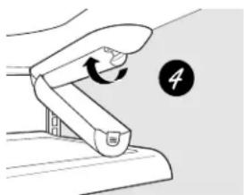
natural_image
Diagram of a hand gripping a device with a circular arrow and number 4 (no text or symbols on the device itself)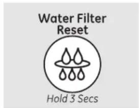
text_image
Water Filter Reset Hold 3 Secstext_image
RESET FILTER Hold 3 seconds to resetnatural_image
Diagram showing two hands pressing down on a rectangular object with arrows indicating motion (no text or symbols)text_image
Technical diagram showing two labeled components (① and ②) with directional arrows indicating flow or movement.Remise en place :
natural_image
Line drawing of hands holding a rectangular tray or shelf (no text or symbols)natural_image
Illustration of hands holding a rectangular object with a downward arrow, no text or symbols presentnatural_image
Line drawing of a rectangular device with an open lid and a downward arrow indicating a drop or compression (no text or symbols)natural_image
Simple line drawing of a rectangular device with a downward arrow indicating force or movement (no text or symbols)natural_image
Technical line drawing of a mechanical component with internal channels (no text or symbols)natural_image
Line drawing of a double-bay refrigerator with top and front panels (no text or symbols)natural_image
Pure diagram of a vehicle front view with two rectangular compartments and a circular component on the side (no text or symbols)text_image
Color Soilnatural_image
Line drawing of a two-tiered storage unit or rack with no text or symbolsnatural_image
Simple line drawing of a diagonal line with two circular components and a hanging hook (no text or symbols)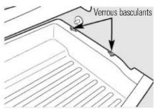
text_image
Verrous basculantstext_image
Technical diagram of a multi-tiered storage unit with numbered components, likely for industrial or warehouse inspection.natural_image
Diagram of a refrigerator interior showing internal structure with arrows indicating movement (no text or symbols)natural_image
Technical line drawing of a mechanical assembly with internal components and a highlighted section (no text or symbols)natural_image
Diagram of a refrigerator interior showing drawer, rack, and door mechanism (no text or labels)natural_image
Illustration of hands holding a document with a downward arrow indicating compression (no text or symbols present)natural_image
Hand holding a tray with a black arrow pointing to a container (no text or symbols visible)text_image
6 mm (1/4 po) maxCompartiment congélation max. 8 kg (18 lbs).
text_image
8 mm (5/16 po) 6 mm (1/4 po) max 19 mm (3/4 po)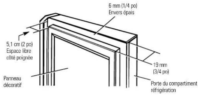
natural_image
Simple line drawing of a screwdriver with a magnified view of the tip (no text or symbols)Tournevis cruciforme
text_image
Diagram showing a power plug connected to two wall-mounted electrical outlets, with an arrow indicating direction.natural_image
Mechanical assembly diagram showing components like gears and springs (no text or labels)Vis de réglage
text_image
Logo A B stations montagetext_image
Technical diagram showing a mechanical assembly with labeled component A and a circular component with a diagonal line.8 FIXEZ LA POIGNÉE DE LA PORTE DU COMPARTIMENT ALIMENTS FRAIS
natural_image
Simple line drawing of a rectangular object with a circular inset showing a hammer and sickle (no text or symbols)natural_image
Technical line drawing of a mechanical assembly with two circular insets showing internal components (no text or symbols)natural_image
Pure mechanical diagram showing a bracket with two arrows indicating rotational motion (no text or symbols)text_image
Technical diagram of a refrigerator interior with labeled parts A, B, and C showing internal structure and directional arrows.② ENLEVEZ L'AVANT DU TIROIR DES GUIDES
natural_image
Technical line drawing of a structural component with two circular insets showing internal components (no text or symbols)natural_image
Technical line drawing of a refrigerator interior showing door, shelf, and drawer (no text or symbols)natural_image
Technical line drawing of a mechanical assembly with an inset showing a magnified view of internal components (no text or symbols)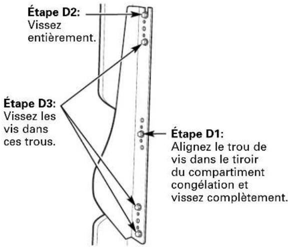
natural_image
Technical line drawing of a refrigerator interior showing internal compartments and doorways (no text or symbols)CHANGEMENT DU SENS D'OUVERTURE DES PORTES
natural_image
Pure technical line drawing of a structural connection detail (no text or symbols)natural_image
Technical line drawing of a mechanical assembly with an upward arrow indicating motion (no text or symbols)natural_image
Technical line drawing of a mechanical bracket with screws and a cylindrical component (no text or symbols)③ INSTALLATION DE LA CHARNIÈRE DU CENTRE
natural_image
Pure diagram of a curved arrow and hanging chain without any text, numbers, or symbolsnatural_image
Technical line drawing of a mechanical clamp or bracket assembly with mounting holes (no text or symbols)text_image
Diagram showing mechanical assembly with labeled parts A and B, including screws and holesnatural_image
Technical line drawing of a mechanical component with bolts and a labeled point (no text or symbols)natural_image
Technical line drawing of a mechanical bracket with a downward arrow indicating force or direction (no text or symbols)natural_image
Technical line drawing of a mechanical assembly with mounting bracket and clamping mechanism (no text or symbols)7 FIXEZ LE LOGO
natural_image
Technical line drawing of a mechanical clamp or bracket assembly with a separate inset showing a dashed-line component (no text or symbols)natural_image
Diagram of a screwdriver with a magnified view of the tip (no text or symbols)Tournevis cruciforme
① ENLÈVEMENT DES PORTES DU COMPARTIMENT RÉFRIGÉRATION
natural_image
Pure technical line drawing of a mechanical or architectural component with no text, numbers, or symbolstext_image
Technical diagram showing mechanical assembly with labeled components and a downward arrow indicating directionC2
Raccord d'eau
natural_image
Technical line drawing of a mechanical bracket with an upward arrow indicating motion (no text or symbols)natural_image
Technical line drawing of a mechanical bracket with mounting holes and a cylindrical component (no text or symbols)② ENLÈVEMENT DE LA PORTE OPPOSÉE
natural_image
Technical line drawing of a mechanical clamp or bracket assembly with two screws (no text or symbols)② RE-SUSPENSION DES PORTES DU COMPARTIMENT RÉFRIGÉRATION
natural_image
Technical diagram showing a mechanical assembly with arrows indicating force or movement (no text or symbols present)natural_image
Simple line drawing of a tool interacting with a curved object (no text or symbols)4 FIXEZ LE ROBINET D'ARRÊT
natural_image
Simple line drawing of a cylindrical object with a cut section, no text or symbols present
natural_image
Illustration of a hand holding a device with a downward arrow, no text or symbols present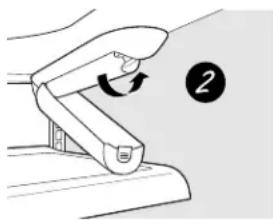
natural_image
Illustration of a hand gripping a device with a circular arrow and number 2 (no text or symbols on the device itself)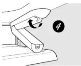
natural_image
Diagram of a hand gripping a device with a circular arrow and number 4, no text or symbols present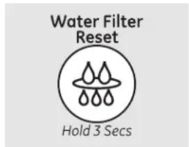
text_image
Water Filter Reset Hold 3 Secstext_image
RESET FILTER Hold 3 seconds to resettext_image
Diagram showing two labeled arrows pointing to a rectangular object with a base, likely illustrating a physical or engineering concept.text_image
Technical diagram showing two labeled components (① and ②) with directional arrows indicating flow or movement.Para reemplazarlo:
natural_image
Simple line drawing of a tray with hands holding it, no text or symbols presentnatural_image
Illustration of hands holding a rectangular object with a downward arrow, no text or symbols presentnatural_image
Line drawing of a printer with an open lid and arrow indicating compression (no text or symbols)natural_image
Simple line drawing of a rectangular device with a downward arrow indicating motion or force (no text or symbols)natural_image
Technical line drawing of a mechanical component with internal channels (no text or symbols)natural_image
Line drawing of a mechanical device with a base and top component (no text or symbols)natural_image
Pure technical line drawing of a symmetrical mechanical or architectural component with two rectangular cutouts and two circular features (no text or symbols)natural_image
Line drawing of a two-tiered storage unit or rack with no text or symbolsnatural_image
Simple line drawing of a cable with two hanging components (no text or symbols)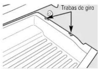
text_image
Trabas de gironatural_image
Pure technical line drawing of a mechanical or electrical component with no text, numbers, or symbolstext_image
Diagram of a multi-tiered storage or rack system with numbered components, likely for industrial or warehouse management.natural_image
Diagram of a refrigerator interior showing internal compartments and a window with arrows indicating movement (no text or symbols)natural_image
Technical line drawing of a mechanical assembly with two views of a device (no text or symbols)natural_image
Diagram of a refrigerator interior showing stairs and storage compartments (no text or symbols)natural_image
Illustration of hands holding a document with a downward arrow, no text or symbols presentLuces del refrigerador
natural_image
Hand holding a ceiling-mounted device with a black arrow indicating force or motion (no text or symbols visible)text_image
Relleno 3/4" (19 mm) 3/4" (19 mm) 2 1/2" (63,5 mm) Paneltext_image
Relleno 3/4" (19 mm) 3/4" (19 mm) 2 1/2" (63.5 mm) Panel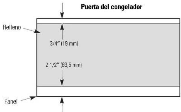
text_image
Puerta del congelador Relleno 3/4" (19 mm) 2 1/2" (63,5 mm) Paneltext_image
5/16" (8 mm) 1/4" (6 mm) max. 3/4" (19 mm)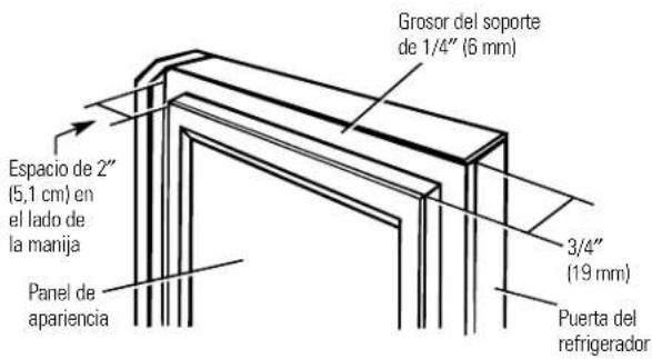
natural_image
Diagram of a screwdriver with a magnified view of the tip (no text or symbols)Destornillador Phillips
Llaves Allen de 3/32", 1/8"y 1/4"
text_image
Diagram showing a plug-in socket connected to two wall-mounted electrical outlets with I/O labelsnatural_image
Mechanical assembly diagram showing components and directional arrows (no text or labels)natural_image
Pure technical diagram of a mechanical assembly with two circular components and a bracket (no text or symbols)⑧ SUJETE LA MANIJA DE LA PUERTA DE ALIMENTOS FRESCOS
Manija de acero inoxidable:
natural_image
Simple line drawing of a rectangular box with a circular inset showing a letter 'J' and an 'A' label (no text or symbols beyond labels)natural_image
Technical line drawing of a mechanical assembly with two circular insets showing internal components (no text or symbols)natural_image
Pure technical diagram of a mechanical joint or bracket with no text, numbers, or symbolstext_image
InterruptorNOTA:
text_image
Technical diagram of a refrigerator interior with labeled parts A, B, C, D and directional arrows indicating movement or flow.natural_image
Technical line drawing of a structural component with two circular insets showing internal components (no text or symbols)natural_image
Technical line drawing of a refrigerator interior showing door, seat, and shelf (no text or symbols)natural_image
Technical line drawing of a refrigerator interior showing internal compartments and door handle (no text or symbols)CÓMO INVERTIR EL VAIVÉN DE LA PUERTA
natural_image
Isometric line drawing of a 3D rectangular block with vertical connectors (no text or symbols)natural_image
Pure mechanical assembly diagram showing a bracket with an upward arrow and mounting base (no text or symbols)natural_image
Technical line drawing of a mechanical assembly with mounting brackets and bolts (no text or symbols)③ INSTALE LA BISAGRA CENTRAL
natural_image
Pure mechanical diagram showing a curved arrow and linkage without any text, numbers, or symbolsnatural_image
Technical line drawing of a mechanical clamp or bracket assembly with screws, no text or symbols presenttext_image
Technical diagram showing a mechanical clamp or bracket assembly with labeled points A and Bnatural_image
Technical line drawing of a mechanical assembly with mounting holes and a labeled component (no text or symbols)natural_image
Mechanical component diagram showing a downward arrow and a cylindrical pin (no text or symbols)natural_image
Technical line drawing of a mechanical assembly with mounting bracket and clamping mechanism (no text or symbols)7 INSTALE LA INSIGNIA DEL LOGO
natural_image
Technical line drawing of a mechanical clamp or bracket assembly with a separate panel view (no text or symbols)CÓMO RETIRAR LAS PUERTAS
natural_image
Pure technical line drawing of a mechanical component with no text or symbolsnatural_image
Mechanical diagram showing a lever mechanism with a downward arrow indicating motion (no text or symbols present)C2
Conexión de agua
natural_image
Technical line drawing of a mechanical bracket with an upward arrow indicating force or direction (no text or symbols present)natural_image
Technical line drawing of a mechanical bracket with mounting holes and dashed alignment lines (no text or symbols)natural_image
Technical line drawing of a mechanical clamp or bracket assembly (no text or symbols)2 VUELVA A COLGAR LAS PUERTAS DEL REFRIGERADOR
natural_image
Pure mechanical diagram showing a bracket with two circular arrows indicating rotation or force direction (no text or symbols)natural_image
Simple line drawing of a tool with a curved handle and a pointed tip, no text or symbols present.natural_image
Simple line drawing of a flower with a curved arrow, no text or symbols presentHecho por General Electric, Appliance Park, Louisville, KY 40225
General Manager, Customer Relations
GE Appliances, Appliance Park
Louisville, KY 40225
Registre su electrodoméstico ge.com
Have a question or need assistance with your appliance? Try the GE Appliances Website 24 hours a day, any day of the year! For greater convenience and faster service, you can now download Owner's Manuals, order parts or even schedule service on-line. In Canada: www.geappliances.ca
Schedule Service
In the U.S.: ge.com
Expert GE repair service is only one step away from your door. Get on-line and schedule your service at your convenience 24 hours any day of the year! Or call 800.GE.CARES (800.432.2737) during normal business hours.
In Canada, call 1.800.561.3344
Real Life Design Studio
In the U.S.: ge.com
GE supports the Universal Design concept—products, services and environments that can be used by people of all ages, sizes and capabilities. We recognize the need to design for a wide range of physical and mental abilities and impairments. For details of GE's Universal Design applications, including kitchen design ideas for people with disabilities, check out our Website today. For the hearing impaired, please call 800.TDD.GEAC (800.833.4322).
In Canada, contact: Manager, Consumer Relations, Mabe Canada Inc.
Suite 310, 1 Factory Lane
Moncton, N.B. E1C 9M3
Extended Warranties
In the U.S.: ge.com
Purchase a GE extended warranty and learn about special discounts that are available while your warranty is still in effect. You can purchase it on-line anytime, or call 800.626.2224 during normal business hours. GE Consumer Home Services will still be there after your warranty expires. In Canada, call 1.888.261.2133
Parts and Accessories
In the U.S.: ge.com
Individuals qualified to service their own appliances can have parts or accessories sent directly to their homes (VISA, MasterCard and Discover cards are accepted). Order on-line today, 24 hours every day or by phone at 800.626.2002 during normal business hours.
Instructions contained in this manual cover procedures to be performed by any user. Other servicing generally should be referred to qualified service personnel. Caution must be exercised, since improper servicing may cause unsafe operation.
Customers in Canada should consult the yellow pages for the nearest Mabe service center, or call 1.888.261.3055.

Contact Us
In the U.S.: ge.com
If you are not satisfied with the service you receive from GE, contact us on our Website with all the details including your phone number, or write to: General Manager, Customer Relations
GE Appliances, Appliance Park
Louisville, KY 40225
In Canada: www.geappliances.ca, or write to:
Director, Consumer Relations, Mabe Canada Inc.
Suite 310, 1 Factory Lane
Moncton, N.B. E1C 9M3

Register Your Appliance
In the U.S.: ge.com
Register your new appliance on-line—at your convenience! Timely product registration will allow for enhanced communication and prompt service under the terms of your warranty, should the need arise. You may also mail in the pre-printed registration card included in the packing material. In Canada: www.geappliances.ca