PJD23BYWFS - Fridge GE - Free user manual and instructions
Find the device manual for free PJD23BYWFS GE in PDF.

User questions about PJD23BYWFS GE
0 question about this device. Answer the ones you know or ask your own.
Ask a new question about this device
Download the instructions for your Fridge in PDF format for free! Find your manual PJD23BYWFS - GE and take your electronic device back in hand. On this page are published all the documents necessary for the use of your device. PJD23BYWFS by GE.
USER MANUAL PJD23BYWFS GE
SAFETY INFORMATION ..... 3
OPERATING INSTRUCTIONS
Features....6
Controls 8
Sabbath Mode 8
Autofill^* 10
WiFi 11
Demand Response 12
Water Filter 13
Refrigerator Storage Options..... 14
Climate Zone 16
Convertible Drawer 16
Freezer 17
Automatic Icemaker 19
CARE AND CLEANING ..... 20
Replacing the Lights 21
INSTALLATION INSTRUCTIONS
Preparing to Install the
Refrigerator 22
Installing the Refrigerator ..... 2 6
Installing the Water Line ..... 3 8
TROUBLESHOOTING......41
Normal Operating Conditions ..... 41
Troubleshooting Tips 42
Truth or Myth 44
LIMITED WARRANTY ..... 4 6
CONSUMER SUPPORT
XWFE Water Filter Cartridge
Limited Warranty 47
Performance Data Sheet 48
Consumer Support 52
*Select Models Only
Write the model and serial numbers here:
Model # ____
Serial # ____
Find these numbers on a label on the left side, near the middle of the refrigerator compartment.
OWNER'S MANUAL & INSTALLATION INSTRUCTIONS
PGD, PGE, PJD, PJE, PAD and PHD
ENGLISH/FRANÇAIS/ ESPAÑOL
THANK YOU FOR MAKING GE APPLIANCES A PART OF YOUR HOME.
Whether you grew up with GE Appliances, or this is your first, we're happy to have you in the family.
We take pride in the craftsmanship, innovation and design that goes into every GE Appliances product, and we think you will too. Among other things, registration of your appliance ensures that we can deliver important product information and warranty details when you need them.
Register your GE appliance now online. Helpful websites and phone numbers are available in the Consumer Support section of this Owner's Manual. You may also mail in the pre-printed registration card included in the packing material.

GE APPLIANCES
IMPORTANT SAFETY INFORMATION READ ALL INSTRUCTIONS BEFORE USING THE APPLIANCE
WARNING
To reduce the risk of fire, explosion, electric shock, or injury when using your refrigerator, follow these basic safety precautions:
■ This refrigerator must be properly installed and located in accordance with the Installation Instructions before it is used.
■ Unplug the refrigerator before making repairs or cleaning.
NOTE: Power to the refrigerator cannot be disconnected by any setting on the control panel.
NOTE: Repairs must be performed by a qualified Service Professional.
■ Replace all parts and panels before operating.
■ Do not use an extension cord.
- Keep flammable materials and vapors away from the refrigerator.
■ Do not store explosive substances such as aerosol cans with a flammable propellant in this appliance.
■ To prevent suffocation and entrapment hazards to children, remove the refrigerator and freezer doors from any refrigerator before disposing of it or discontinuing its use.
■ To avoid serious injury or death, children should not stand on, or play in or with the appliance.
Children and persons with reduced physical, sensory or mental capabilities or lack of experience and knowledge can use this appliance only if they are supervised or have been given instructions on safe use and understand the hazards involved.
This appliance is intended to be used in household and similar applications such as: staff kitchen areas in shops, offices and other working environments; farm houses; by clients in hotels, motels, bed & breakfast and other residential environments; catering and similar non-retail applications.
■ Connect to potable water supply only. A cold water supply is required for automatic icemaker operation. The water pressure must be between 40 and 120 psi (275-827 kilopascals).
- Do not apply harsh cleaners to the refrigerator. Certain cleaners will damage plastic which may cause parts such as the door or door handles to detach unexpectedly. See the Care and Cleaning section in your Owner's Manual for detailed instructions.
CAUTION
To reduce the risk of injury when using your refrigerator, follow these basic safety precautions:
- Do not clean glass shelves or covers with warm water when they are cold. Glass shelves and covers may break if exposed to sudden temperature changes or impact, such as bumping or dropping. Tempered glass is designed to shatter into many small pieces if it breaks.
- Keep fingers out of the “pinch point” areas; clearances between the doors and between the doors and cabinet are necessarily small. Be careful closing doors when children are in the area.
■ Do not refreeze frozen foods which have thawed completely.
■ Do not touch the cold surfaces in the freezer compartment when hands are damp or wet, skin may stick to these extremely cold surfaces.
In freezers with automatic icemakers, avoid contact with the moving parts of the ejector mechanism, or with the heating element that releases the cubes. Do not place fingers or hands on the automatic ice making mechanism while the freezer is plugged in.
■ Use a sturdy glass when dispensing ice (on models with ice dispenser).
■ Install the AutoFill Pitcher fully in its base to prevent it from falling out when the refrigerator door is opened. The pitcher is heavy when full of water and could cause injury if it falls out or is dropped.
WARNING

RE OR EXPLOSION HAZARD
Keep flammable materials and vapors away from refrigerator. Failure to do so can result in fire, explosion, or death.
READ AND SAVE THESE INSTRUCTIONS
IMPORTANT SAFETY INFORMATION READ ALL INSTRUCTIONS BEFORE USING THE APPLIANCE
WARNING

RE OR EXPLOSION HAZARD Flammable Refrigerant
This appliance contains isobutane refrigerant, also known as R600a, a natural gas with high environmental compatibility. However, it is also combustible. Adhere to the warnings below to reduce the risk of injury or property damage.
■ When handling, installing and operating the appliance, care should be taken to avoid damage to the refrigerant tubing.
■ Service shall only be performed by authorized service personnel. Use only manufacturer-authorized service parts.
■ Dispose of refrigerator in accordance with Federal and Local Regulations. Flammable refrigerant and insulation material used require special disposal procedures. Contact your local authorities for the environmentally safe disposal of your refrigerator.
- Keep ventilation openings in the appliance enclosures or in the built-in structure clear of obstruction.
■ To remove frost, scrape with a plastic or wood spatula or scraper. Do not use an ice pick, metal, or sharp-edged instrument as it may puncture the freezer liner and then the flammable refrigerant tubing behind it.
■ Do not use electrical appliances inside the food storage compartment of the appliance.
■ Do not use any electrical device in defrosting your freezer.
WARNING
To reduce the risk associated with choking, do not allow children under 3 years of age to have parts during the installation of this product.
WARNING

OVER HAZARD
If an anti-tip floor bracket was included with your refrigerator, install it to prevent the refrigerator from tipping forward, which could result in death or serious injury. Read and follow the entire installation instructions for installing the anti-tip floor bracket packed with your refrigerator.
READ AND SAVE THESE INSTRUCTIONS
IMPORTANT SAFETY INFORMATION READ ALL INSTRUCTIONS BEFORE USING THE APPLIANCE
CONNECTING ELECTRICITY
WARNING

LECTRICAL SHOCK HAZARD
Plug into a grounded 3-prong outlet
Do not remove the ground prong
Do not use an adapter
Do not use an extension cord
Failure to follow these instructions can result in
death, fire, or electrical shock
Do not, under any circumstances, cut or remove the third (ground) prong from the power cord. For personal safety, this appliance must be properly grounded.
■ The power cord of this appliance is equipped with a 3-prong (grounding) plug which mates with a standard 3-prong (grounding) wall outlet to minimize the possibility of electric shock hazard from this appliance.
■ Have the wall outlet and circuit checked by a qualified electrician to make sure the outlet is properly grounded.
■ Where a standard 2-prong wall outlet is encountered, it is your personal responsibility and obligation to have it replaced with a properly grounded 3-prong wall outlet. Do not use an adapter.
■ The refrigerator should always be plugged into its own individual electrical outlet which has a voltage rating that matches the rating plate.
■ A 115 Volt AC, 60 Hz, 15- or 20-amp fused, grounded electrical supply is required. This provides the best performance and also prevents overloading house wiring circuits which could cause a fire hazard from overheated wires.
■ Never unplug your refrigerator by pulling on the power cord. Always grip plug firmly and pull straight out from the outlet.
- Immediately discontinue use of a damaged supply cord. If the supply cord is damaged, it must be replaced by a qualified service professional with an authorized service part from the manufacturer.
■ When moving the refrigerator away from the wall, be careful not to roll over or damage the power cord.
PROPER DISPOSAL OF YOUR OLD REFRIGERATOR
WARNING
SUFFOCATION AND ENTRAPMENT HAZARD
Failure to follow these disposal instructions can result in death or serious injury
IMPORTANT: Child entrapment and suffocation are not problems of the past. Junked or abandoned refrigerators are still dangerous even if they will sit for "just a few days." If you are getting rid of your old refrigerator, please follow the instructions below to help prevent accidents.
Before You Throw Away Your Old Appliance
■ Take off the fresh food and freezer doors.
■ Leave the shelves in place so that children may not easily climb inside.
REFRIGERANT AND FOAM DISPOSAL:
Dispose of or recycle your appliance in accordance with Federal and Local Regulations. Flammable refrigerant and insulation material used requires special disposal procedures. Contact your local authorities for the environmentally safe disposal or recycling of your refrigerator.
READ AND SAVE THESE INSTRUCTIONS
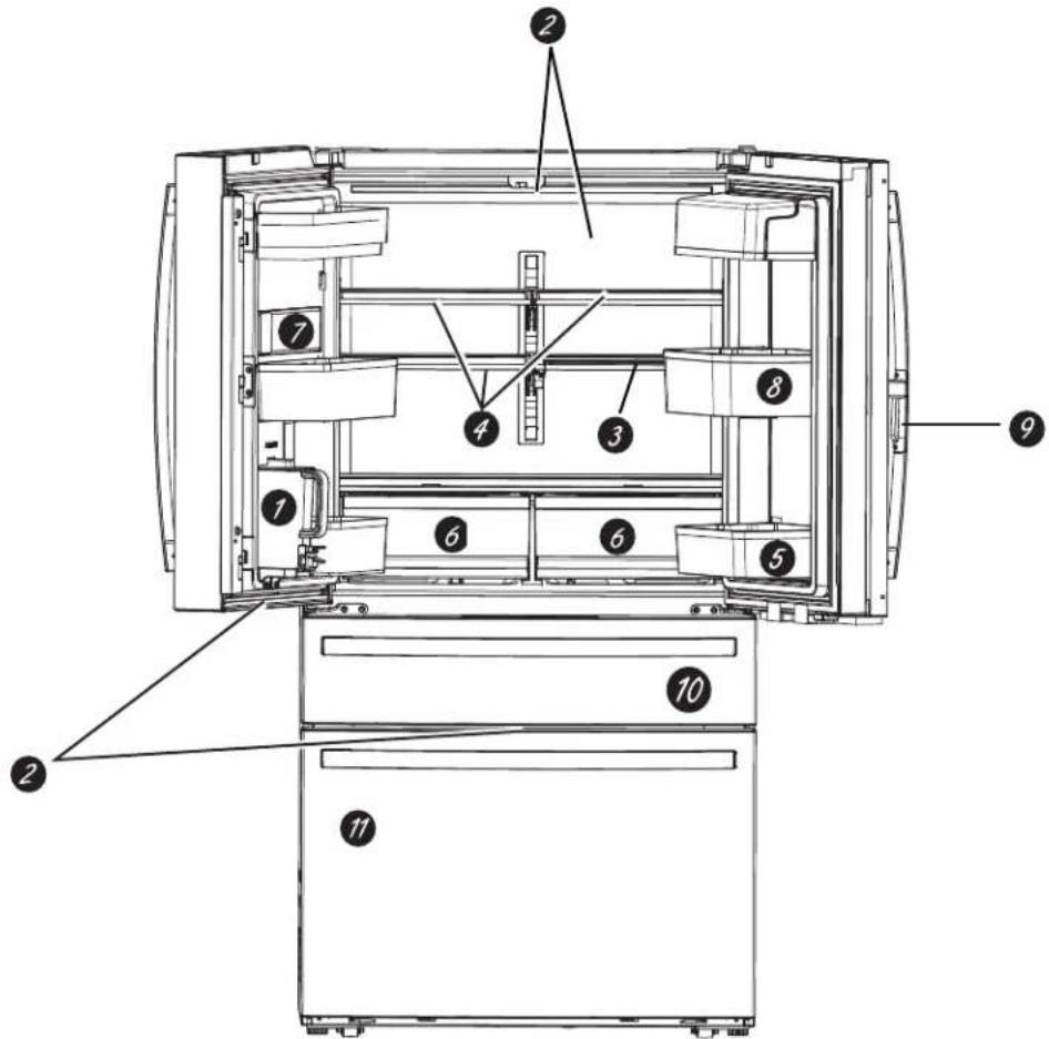
Features
Profile Models PGD, PGE, PJD and PJE
text_image
Technical diagram of a refrigerator internal structure with numbered components for identification1 Autofill Pitcher
Designed for hands-free refilling to provide constantly available chilled filtered water.
2 Showcase LED lighting
LED lighting is positioned throughout the interior to spotlight areas in the refrigerator. LEDs are located under the refrigerator door to light the convertible drawer, and LEDs are under the convertible drawer to light the freezer drawer.
3 QuickSpace™ shelf
Functions as a normal full-sized shelf when needed and easily slides back to store tall items below.
4 Spillproof shelves
Designed to capture your spills for easier clean up.
5 Removable door bin
Can be removed for those with a wall limiting the door opening.
6 Climate zone bin
Separate bins for produce storage.
7 Water filter
Filters water and ice. Certified to reduce chlorine-resistant cysts, lead, select pharmaceuticals, and more. For easy filter replacement instructions, see page 13.
8 Rotating Bin (on some models)
Can be rotated out for easy access.
9 Door in Door Latch (on some models)
Squeeze the latch on the underside of the handle to open the outer door.
10 Convertible drawer
Select the best temperature to store your food.
11 Icemaker
Ice storage in the upper left Freezer compartment drawer.
Profile Models PAD and PHD
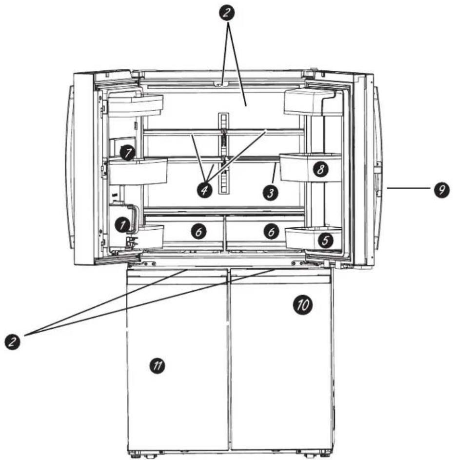
text_image
Technical diagram of a device with numbered components for identification and assembly reference.1 Autofill Pitcher
Designed for hands-free refilling to provide constantly available chilled filtered water.
2 Showcase LED lighting
LED lighting is positioned throughout the interior to spotlight areas in the refrigerator.
3QuickSpace™ shelf
Functions as a normal full-sized shelf when needed and easily slides back to store tall items below.
4 Spillproof shelves
Designed to capture your spills for easier clean up.
5 Removable door bin
Can be removed for those with a wall limiting the door opening.
6 Climate zone bin
Separate bins for produce storage.
7 Water filter
Filters water and ice. Certified to reduce chlorine-resistant cysts, lead, select pharmaceuticals, and more. For easy filter replacement instructions, see page 13.
8 Rotating Bin (on some models)
Can be rotated out for easy access.
9 Door in Door Latch (on some models)
Squeeze the latch on the underside of the handle to open the outer door.
10 Convertible Zone
Select the best temperature to store your food.
11 Icemaker
Ice storage in the upper left Freezer compartment drawer.
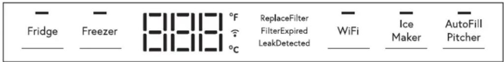
Controls
All Models
We are continuously updating our software. Please reference the full owner's manual online for the latest functionality at GEAppliances.com. In Canada, visit GEAppliances.ca.
The recommended temperature settings, preset from the factory, are 37^ F ( 3^ C) for the refrigerator and 0^ F (-18°C) for the freezer.
text_image
Fridge Freezer 81111 °F °C ReplaceFilter FilterExpired LeakDetected WiFi Ice Maker AutoFill PitcherNOTE: The refrigerator is shipped with protective film covering the temperature controls.
If this film was not removed during installation, remove it now.
The temperature controls are preset in the factory at 37^ F ( 3^ C) for the refrigerator compartment and 0^ F (-18°C) for the freezer compartment. Allow 24 hours for the temperature to stabilize to the preset recommended settings.
To Change the Refrigerator Temperature:
Press Fridge button to scroll through available temperature settings 34^ F ( 1^ C) to 42^ F ( 6^ C). Note the set temp will loop back to the lowest setting upon indexing the Fridge button at the highest setting.
Press Freezer button to scroll through available temperature settings -6^ ( -21^ ) to 5^ ( -15^ ). Note the set temp will loop back to the lowest setting upon indexing the Freezer button at the highest setting.
The cooling system can be turned off without shutting off electrical power to the refrigerator. Press Fridge,
Freezer and Ice Maker buttons for 3 seconds to toggle cooling system on/off. CS followed by OFF or ON will be displayed.
Control Settings
- Press Fridge and Ice Maker buttons for 3 seconds to toggle between Door Alarm On/Off.
- Press Ice Maker button to toggle icemaker on/off.
- Press WiFi button to turn WiFi on. Press and hold WiFi button for 3 seconds to turn WiFi off.
- Press AutoFill Pitcher button to toggle AutoFill Pitcher on/off.
Press Fridge or Freezer button to display temp then press and hold Freezer and Ice Maker buttons for 3 seconds to toggle between Celsius and Fahrenheit.
Volume Control:
Press and hold Freezer and AutoFill Pitcher buttons for 3 seconds to toggle sound level between "Hi", "Lo" and "Off".
Sabbath Mode:
Press and hold Freezer, Ice Maker and AutoFill Pitcher buttons for 3 seconds to toggle Sabbath Mode on/off.
Sabbath Mode OU (Orthodox Union) and CRC (Central Rabbinical Congress)
This refrigerator offers an OU and CRC Sabbath mode that complies with standards set forth by Orthodox Union, the Central Rabbinical Congress, and Halacha Tech, and is 100% certified to the highest halacha standards. In order to enable the OU and CRC Sabbath mode, a separate Shabbos Keeper for Refrigerators must be connected to the refrigerator. The Shabbos Keeper can be purchased from zmantechnologies.com or geappliances.com. The only way to enable the OU and CRC Sabbath mode is with the purchase of the Shabbos Keeper for Refrigerators. The Shabbos Keeper
connects to your refrigerator to automatically enable Shabbos compatible modes each week and before every holiday. The appropriate mode will automatically activate based on the Jewish calendar date for your location. When the Shabbos Keeper is properly connected to the refrigerator, the display will show "SA".

text_image
U CRC T POWERED BY: ZMAN TECHXWFE Filter Cartidge
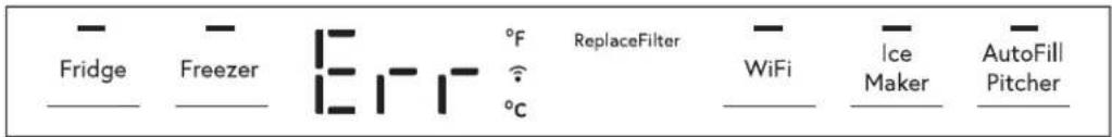
text_image
Fridge Freezer °C °F °C ReplaceFilter WiFi Ice Maker AutoFill PitcherTop Controls Display will illuminate as follows:
- Replace Filter when 10% life remains
- Leak Detected when water is detected at filter indicating a leak is present.
- Expired Filter when the filter has been in use for 6 months
- Err when no filter is present or the wrong filter is installed
For all conditions, the display will automatically reset when fault condition is corrected.
Model PGD, PGE, PJD and PJE Convertible Drawer
Temperature in the Convertible Drawer is selected by pressing the food item to be kept in the drawer.
Meat 29^ F ( -2^ C)
Beverages 33^ F ( 1^ C)
Snacks 37°F (3°C)
Wine 42^ F ( 6^ C)
The temperature setting is locked by default.
Button must be pressed for 3 seconds to unlock.
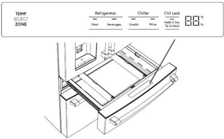
text_image
TEMP SELECT ZONE Refrigerator Meat Beverages Chiller Snacks Wine Ctrl Lock — Hold 3 Sec To Unlock 1.8 °F °CModel PAD and PHD Convertible Zone
The Convertible Zone control panel is in the top of the lower right-hand door and is used to adjust the temperature
of the convertible zone. Select your desired temperature for this convertible compartment.
Freezer 0^ F ( -18^ C)
Refrigerator 37°F (3°C)
Chiller 42°F (6°C)
The temperature setting is locked by default. Button must be pressed for 3 seconds to unlock.
The Warmer (+) and Cooler (-) buttons can be used to adjust the temperature of each setting.
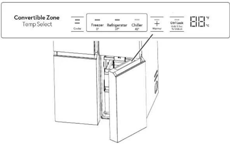
text_image
Convertible Zone Temp Select Cooler Freezer 0° Refrigerator 37° Chiller 42° + Warmer Ctrl Lock Hotel & Serv To Unlock 818 °F °CDispenser
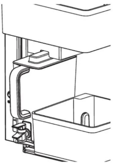
AutoFill Pitcher
Turn the AutoFill Pitcher feature on by pressing the AutoFill Pitcher button on the controls at the top of the fresh food compartment. The LED under the button indicates that the feature is on. Place the lid onto the pitcher so that it fits securely. Align the raised portion of the lid with the slot on the door and slide the pitcher into the door until it fully drops down into the pitcher tray.
The pitcher will automatically fill with water approximately 5 seconds after the door is closed. The pitcher will
not fill with water while the left hand FF door is open. The pitcher will turn off automatically after filling to approximately 60 ounces.
The pitcher is designed to minimize sloshing, but be careful not to open or close door with excessive force to avoid some water sloshing out of the pitcher spout.
The easiest method to remove the lid is to push up on the back overhanging edge of the lid near the handle.
To Clean the AutoFill Pitcher
The AutoFill pitcher and lid are dishwasher safe. The lid should be placed in the top rack only and the pitcher in the bottom rack of the dishwasher. Run on normal wash.
To maximize performance of your AutoFill pitcher, it is recommended that you rinse it thoroughly after washing to remove all soap residue.
If your AutoFill pitcher has been in contact with food that is likely to cause discoloration (e.g. tomato ketchup, mustard), clean your pitcher promptly. This is to avoid possible discoloration of your pitcher.
If you would like to order a secondary AutoFill pitcher go to www.geapplianceparts.com
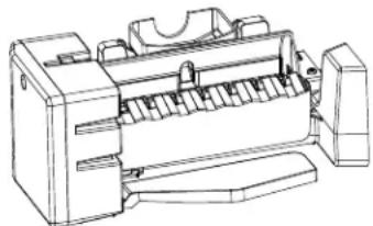
natural_image
Technical line drawing of a mechanical assembly with no visible text or symbolsWiFi (on some models) (for customers in the United States, its territories, and Canada)
If your refrigerator has a Connected Appliance Information label, then it can be connected to your WiFi network, allowing it to communicate with your mobile device for remote monitoring, control and notifications.
Please visit GEAppliances.com/connect to learn more about connected appliance features and learn what connected appliance apps work with your mobile device.
REGULATORY INFORMATION
FCC/IC Compliance Statement:
This device complies with Part 15 of the FCC Rules. Operation is subject to the following two conditions:
- This device may not cause harmful interference, and
-
This device must accept any interference received, including interference that may cause undesired operation.
This equipment has been tested and found to comply with the limits for a Class B digital device, pursuant to Part 15 of the FCC Rules. These limits are designed to provide reasonable protection against harmful interference in a residential installation. This equipment generates uses and can radiate radio frequency energy and, if not installed and used in accordance with the instructions, may cause harmful interference to radio communications. However, there is no guarantee that interference will not occur in a particular installation. If this equipment does cause harmful interference to radio or television reception, which can be determined by turning the equipment off and on, the user is encouraged to try to correct the interference by one or more of the following measures: -
Reorient or relocate the receiving antenna.
- Increase the separation between the equipment and receiver.
- Connect the equipment into an outlet on a circuit different from that to which the receiver is connected.
- Consult the dealer or an experienced radio/television technician for help.
Labelling: Changes or modifications to this unit not expressly approved by the manufacturer could void the user's authority to operate the equipment.
This Product has WiFi capability and requires Internet connectivity and a wireless router to enable interconnection with an Energy Management System, and/or with other external devices, systems or applications.
What is Demand Response?
Some utilities vary their electricity rates based on the time of day. Some utilities offer Demand Response programs to reduce energy usage during certain times of the day. Some utilities may do both things. This refrigerator has a Demand Response feature to help control energy usage.
Using Demand Response without a Utility Program
The Demand Response feature allows the user to shift high energy features, like defrost, for a 4-hour window. This window corresponds to the average peak energy usage. This feature is enabled or disabled with the SmartHQ ^™ and requires the SmartHQ ^™ to operate. It does not depend on the local utility, or whether it varies the electricity rates.
Demand Response with your Utility
If your utility has a compatible Demand Response program, and you are signed up with the utility, this refrigerator can modify its energy usage based on commands received from the utility. The SmartHQ™ can be used to override the Demand Response program, if desired. Please note that there are many different Demand Response programs, and many are not compatible with kitchen appliances. Please check with your local utility.
The demand response level is displayed in the mobile app. Delay appliance load mode (DAL) reduces power consumption by delaying defrost and ice production for 4 hours. Temporary appliance load reduction (TALR) reduces the power consumption by delaying defrost, ice production, and stopping cooling for 10 minutes.
Estimated energy consumption in Watt-hour(Wh) is reported in the mobile app.
Installing Demand Response
Install the SmartHQ™ per the instructions on the previous page. Select the Demand Response page, and choose from the available Demand Response options. The app provides more information on the operation of each Demand Response option.
Demand Response Communication Protocols
This refrigerator uses the following IETF open standard protocols for the WiFi communication. Consult the online user manual for the latest protocol updates:
■ https://mqtt.org/mqtt-specification/
■ http://docs.oasis-open.org/mqtt/mqtt/v3.1.1/os/mqtt-v3.1.1-os.html
GE Appliances API for demand response:
■ Write demand respond status (Inactive, DAL, and TALR)
■ Get demand response status (Inactive, DAL, TALR, or Delay Defrost)
■ Get estimated energy consumption in Watt-hour.
■ Get event for "Door Open"
■ Get event for "High temperature alert"
■ Write demand response (DAL or TALR) start time and duration time period.
■ Get demand response (DAL or TALR) start time and duration time period.
■ Delete demand response (DAL or TALR) schedule.
Water Filter Cartridge
The water filter cartridge is located in the left-hand refrigerator door behind the rectangular access panel.
When to Replace the Filter Cartridge
The Replace Filter message on the control panel will illuminate when the water filter cartridge needs to be replaced soon. The Filter Expired message will illuminate when the water filter cartridge needs to be replaced. The water filter can be replaced earlier if the flow of water to the dispenser or icemaker decreases.
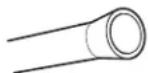
REMOVING THE FILTER
If you are replacing the filter, first remove the previous one by gently grasping the filter and slowly turning it to the left, about a 14 turn. The filter should automatically release itself when you have rotated it far enough to the left. A small amount of water may drip down.
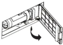
natural_image
Technical line drawing of a mechanical assembly with a rotating component (no text or symbols)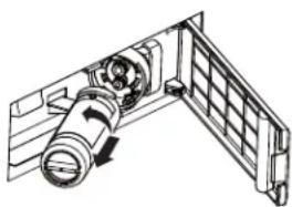
natural_image
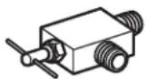
Technical line drawing of a mechanical component with no visible text or symbolsCAUTION
If air has been trapped in the system, the filter cartridge may be ejected as it is removed. Use caution when removing.
FILTER BYPASS PLUG
To reduce the risk of property damage due to water leakage, you MUST use the filter bypass plug when a replacement filter cartridge is not available. Some models do not come equipped with the filter bypass plug. To obtain a free bypass plug, call 800.GECARES and request WR17X33825 filter bypass plug. In Canada, call 800.561.3344. The dispenser and icemaker will not operate without either the filter or bypass plug installed. The bypass plug is installed in the same way as a filter cartridge.
INSTALLING THE FILTER IN A BOTTOM FREEZER REFRIGERATOR
- Open the filter cartridge housing by pulling the door open.
- Line up the ports on the filter with the ports on the filter cartridge holder, and gently insert the filter.
- Slowly turn the filter to the right until it stops. DO NOT OVERTIGHTEN. As you turn the filter, it will automatically adjust itself into position. The filter will move about a 14 turn or 90 degrees, until the filter cannot be turned, and the label faces outward.
- Slowly push the filter up into the clips.
- Close the filter cartridge housing by gently pushing the door closed until the tabs lock into place.
- Confirm that filter fault condition is no longer present on the controls display.
- Immediately after filter change, allow the pitcher to autofill and empty pitcher into sink four times. This will purge the new filter of normal black carbon dust that is discharged during the initial use.
Application Guidelines/Water Supply
| Service Flow 0.5 gpm (1.89 lpm) |
| Water Supply Potable Water |
| Water Pressure 25-120 psi (172-827 kPa) |
| Water Temperature 33°F-100°F (0.6°C-38°C) |
| Capacity 170 gallons (643.5 liters) |
Sign-up for TEXT REMINDERS by texting REPLACE to 70543.
WARNING
To reduce the risk associated with choking, do not allow children under 3 years of age to have access to small parts during the installation of this product. The disposable filter cartridge should be replaced every 6 months at the rated capacity, or sooner if a noticeable reduction in flow rate occurs.
For the maximum benefit of your filtration system, GE Appliances recommends the use of GE Appliances-branded filters only. Using GE Appliances-branded filters in GE Appliances refrigerators provides optimal performance and reliability. GE Appliances filters meet rigorous industry NSF standards for safety and quality that are important for products that are filtering your water. GE Appliances and Hotpoint has not qualified non-GE Appliances-branded filters for use in GE Appliances refrigerators and there is no assurance that non-GE Appliances-branded filters meet GE Appliances standards for quality, performance and reliability.
If you have questions, or to order additional filter cartridges, visit our website at gewaterfilters.com. or call GE Appliances Parts and Accessories, 877-959-8688.
Customers in Canada should consult the yellow pages for the nearest Camco Service Center.
Refrigerator Storage Options
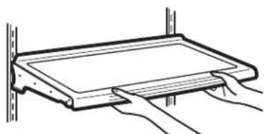
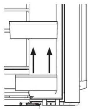
Rearranging the Shelves
Shelves in the refrigerator compartment are adjustable.
To remove:
1 Remove all items from the shelf.
2 Tilt the shelf up at the front.
3 Lift the shelf up at the back and bring the shelf out.
text_image
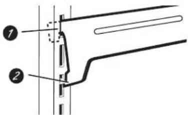
Diagram showing two labeled arrows pointing to a rectangular object with internal layers, possibly illustrating a mechanical or structural concept.To replace:
While tilting the shelf up, insert the top hook at the back of the shelf in a slot on the track.
2 Lower the front of the shelf until the bottom of the shelf locks into place.
text_image
Technical diagram showing two labeled components (1 and 2) of a mechanical or structural assembly with alignment lines and features.
natural_image
Technical line drawing of a rectangular enclosure or storage unit with internal compartments and supports (no text or symbols)Spillproof Shelves
Spillproof shelves have special edges to help prevent spills from dripping to lower shelves.
natural_image
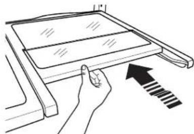
Line drawing of hands holding a rectangular object with a horizontal bar, mounted on a wall (no text or symbols)Quick Space Shelf
This shelf splits in half and slides under itself for storage of tall items on the shelf below.
This shelf can be removed and replaced or relocated (just like spillproof shelves).
NOTE: The back half of the Quick Space Shelf is not adjustable.
natural_image
Line drawing of a hand pressing down on a laptop screen with an arrow indicating motion (no text or symbols)Refrigerator Storage Options
Right Door Bins (on some models)
FIXED BINS can easily be carried from refrigerator to work area.
To remove: Lift bin straight up, then pull out.
ROTATING BIN:
To remove: Rotate bin outward then lift straight up. To remove Place hand under metal base and lift up.
To remove Metal Base: Place hand under metal base and lift up.
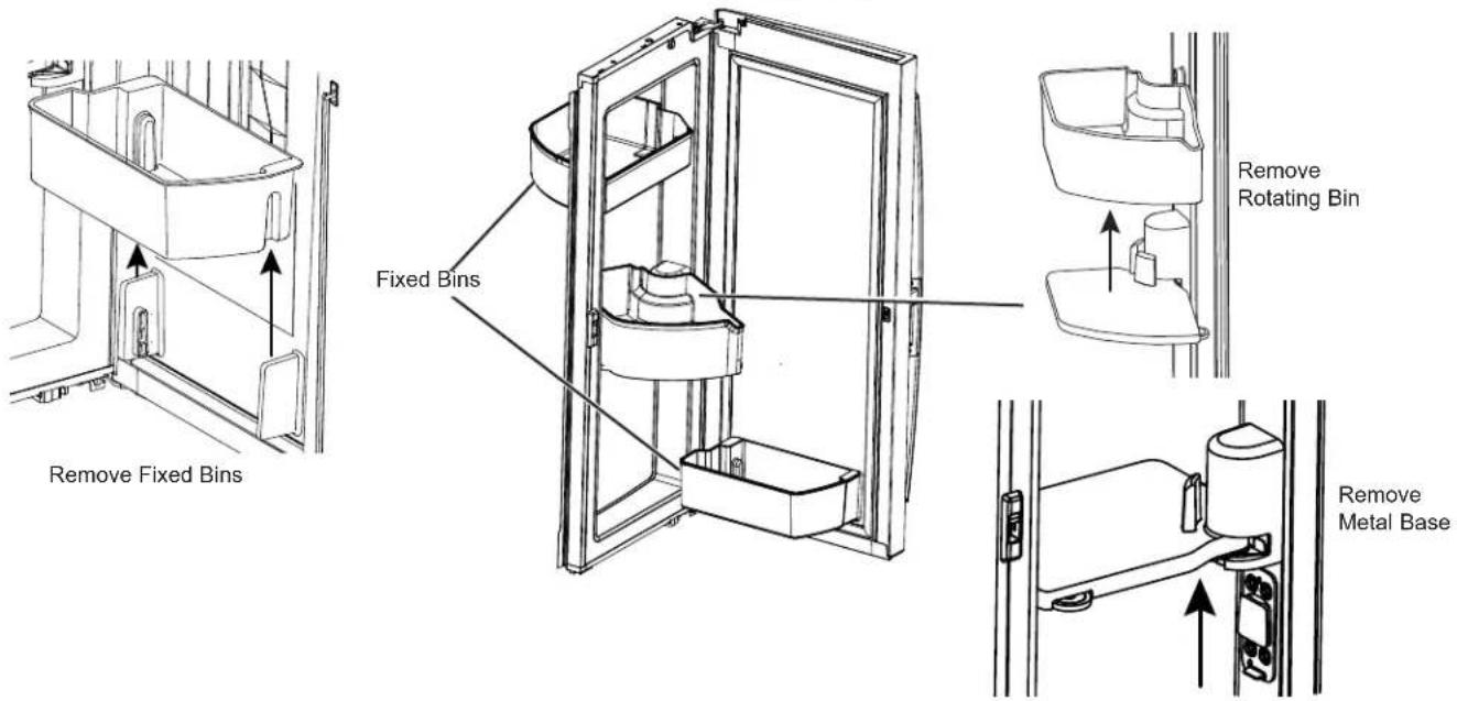
text_image
Remove Fixed Bins Fixed Bins Remove Rotating Bin Remove Metal BaseLeft Door Bins
FIXED BIN
To remove: Lift the bin straight up, then pull out.
The ice maker door bins are not interchangeable, note the location upon removal and replace the bin in its proper location.
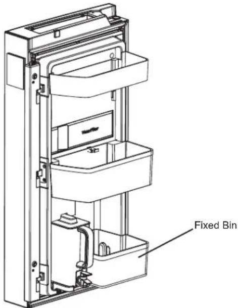
text_image
Fixed BinClimate Zone
Keep fruits and vegetables organized in separate compartments for easy access.
Excess water that may accumulate in the bottom of the drawers or under the drawers should be wiped dry.
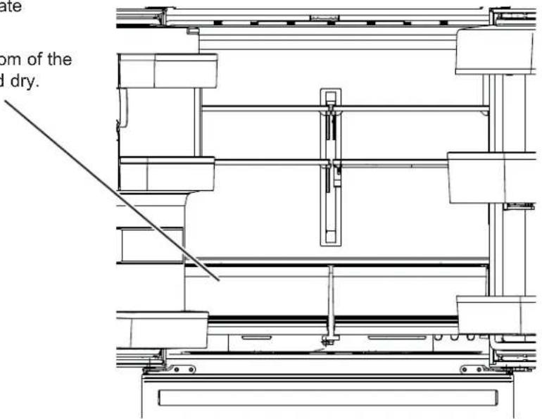
text_image
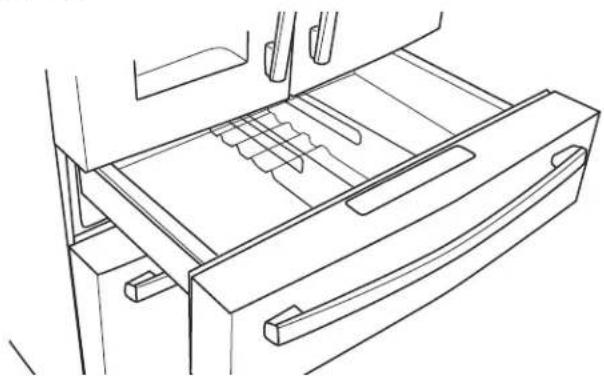
late dom of the l dry.Convertible Drawer
How to Remove and Replace Drawer Organizer
To remove:
- Pull the drawer out to the stop position.
- Slightly raise the organizer, then rotate to remove.
To replace:
- Place the back of the divider on the rear wall of the drawer.
- Rotate the organizer into the desired position.
natural_image
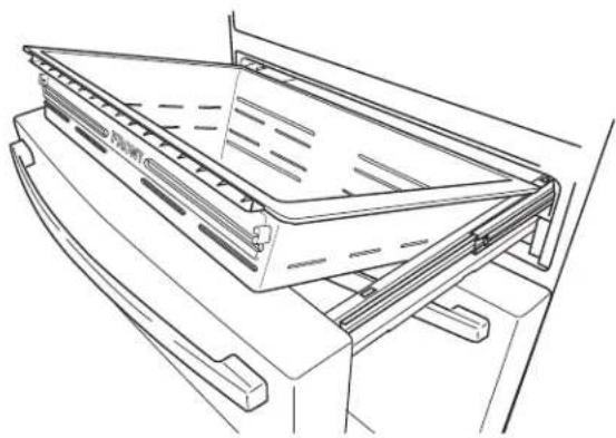
Line drawing of a refrigerator drawer with handle and drawer slot (no text or symbols)How to Remove and Replace Drawer
To remove:
- Pull the drawer out to the stop position.
- Remove the convertible drawer basket by lifting while rotating the basket upward.
To replace:
- Place drawer back in first and rotate drawer front down to seat on slide.
- Push the drawer in to closed position. Convertible drawer basket will be loose if re-installed backwards. Look for "FRONT" emboss to help with re-installation.
natural_image
Line drawing of a mechanical device with a sloped top and base (no text or symbols)Baskets, Drawers, and Bins
Freezer Basket and Drawer
1 Basket.
2 Drawer
3 Ice Bucket
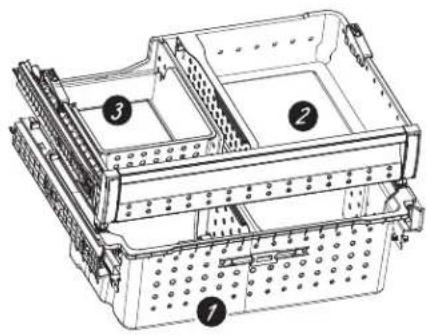
text_image
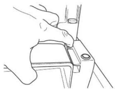
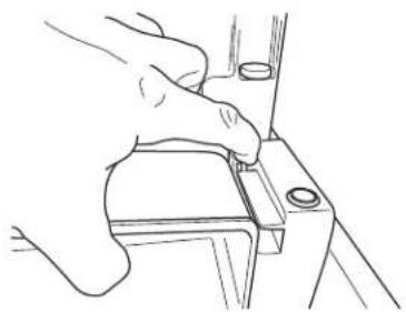
Technical diagram of a multi-level mechanical or electrical device with numbered components labeled 1, 2, and 3.Tilt-Out Bin in the Freezer
To remove:
Press the tab on the right side bracket to remove the freezer drawer bin.
To replace:
Slide bin into location until it locks into place.
natural_image
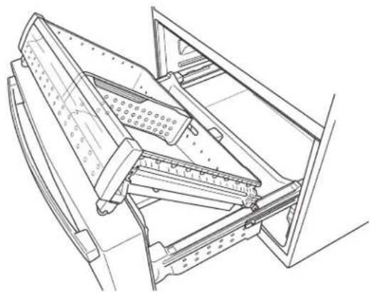
Line drawing of a hand adjusting a mechanical component (no text or symbols)Basket Removal
To remove:
- Pull the top freezer drawer basket forward until it is out of the track in the freezer compartment. Lift, while rotating the basket upward to remove.
- Press the tab on the right side bracket to remove the freezer door bin.
natural_image
Line drawing of a hand using a tool to adjust or install a mechanical component (no text or symbols)- Lift the bottom freezer drawer basket slightly back, then up and out of the drawer.
natural_image
Technical line drawing of a mechanical assembly with no visible text or symbolsTo replace, reverse removal steps.
Refrigerator Storage Options
BASKETS, SHELF, AND BINS - Model PAD and PHD Only
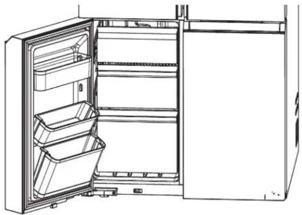
Freezer Door Bin
- Middle and bottom bins on the freezer door can be tilted out for easy access.
natural_image
Line drawing of an open refrigerator with three compartments and one door open (no text or symbols)Select Zone Baskets and Door Bins

natural_image
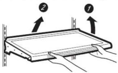
Line drawing of an open refrigerator with visible door, shelves, and ventilation slots (no text or symbols)Fresh Food Basket or Shelf Removal
To remove:
- Pull basket or shelf out all the way.
- Slightly lift front of basket or shelf and pull out.
To replace:
- Reverse the removal steps.
text_image
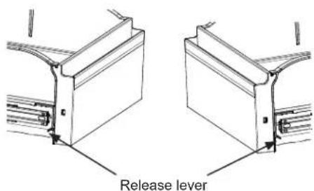
Release leverPHD Freezer or Convertible Zone Basket Removal
To remove:
- Pull the drawer forward to gain access to the side rails.
- Lift the drawer slightly upward with one hand while pushing the release lever back to release the drawer from one side rail.
- Repeat step 3 for the opposite side rail.
- Lift the drawer upward and forward to remove.
To replace:
- Pull both side rails completely forward
- Carefully set the drawer between and on top of the side rails
- Pull each side rail forward till you hear the rail click to engage with the drawer.
- Push the drawer in/out to ensure each rail is re-engaged.
A newly installed refrigerator may take 12 to 24 hours to begin making ice.
WARNING
Connect to potable water supply only.
A cold water supply is required for automatic icemaker operation. The water pressure must be between 40 and 120 psi (275-827 kilopascals).
Automatic Icemaker
The icemaker will produce seven cubes per cycle approximately 100–130 cubes in a 24-hour period, depending on freezer compartment temperature, room temperature, number of door openings and other use conditions.
The icemaker will fill with water when it cools to 15^ F ( -10^ C). A newly installed refrigerator may take 12 to 24 hours to begin making ice cubes.
If the refrigerator is operated before the water line connection is made to the unit or if the water supply to an operating refrigerator is turned off, make sure that the icemaker is turned off. Once the water has been connected to the refrigerator, the icemaker may be turned on using the controls.
You may hear a buzzing sound each time the icemaker fills with water.
Allow 1-2 days for the bucket to completely fill with ice.
Throw away the first few batches of ice to allow the water line to clear.
Be sure nothing interferes with the sweep of the feeler arm.
When the bin fills to the level of the feeler arm, the icemaker will stop producing ice. It is normal for several cubes to be joined together.
natural_image
Technical line drawing of a printer or printer with no visible text, numbers, or symbolsIf ice is not used
frequently, old ice cubes will become cloudy, taste stale and shrink.
NOTE: In homes with lower-than-average water pressure, you may hear the icemaker cycle multiple times when making one batch of ice.
CAUTION
To minimize the risk of personal injury,
avoid contact with the moving parts of the ejector mechanism, or with the heating element that releases the cubes. Do not place fingers or hands on the automatic ice making mechanism while the refrigerator is plugged in.
To turn the icemaker ON/OFF, press the Ice Maker button on the top control panel.
If ice is not used frequently, old ice cubes will become cloudy, taste stale, shrink and fuse together. If you do not plan to use ice frequently, you should empty the bucket regularly or turn off your icemaker by pressing the Ice Maker button on the top control panel.
Cleaning the Outside
FINGERPRINT RESISTANT STAINLESS STEEL*, BLACK STAINLESS, SLATE, DARK SLATE, PAINTED, GLASS - Outside surfaces, door handles, and trim
⚠️ DO NOT use Stainless Steel cleaners on the door surfaces. ⚠️
IMPORTANT: The use of incorrect products may damage the outer finish of Fingerprint Resistant Stainless and Black Stainless models. Please follow these instructions and use only the appropriate items below to clean your appliance surfaces.
- Clean interior/exterior surfaces with warm water, mild soap or detergent, and a soft or microfiber cloth to avoid damage.
- Wipe the appliance surface dry with a soft clean cloth or microfiber towel to avoid streaking or water spotting.
| DO USE DO NOT USE | |
| Soft, clean cloth or spongeMicrofiber cloth | Abrasive cloths, paper towels, scrubbing sponges (with or without soap), scouring or steel wool pads |
| Mild detergent mixed with warm water | Abrasive powders, liquids, or sprays Oven cleanersWindow sprays, ammonia, or bleach Alkaline cleanersCitrus or plant oil-based cleaners Stainless steel cleanersAcidic or vinegar-based cleaners |
*Easily wipe away smudges and fingerprints.
To Clean the AutoFill Pitcher
The AutoFill Pitcher and lid are dishwasher safe. The lid should be placed in the top rack only and the pitcher in the bottom rack of the dishwasher. Run on normal wash.
To maximize performance of your AutoFill pitcher, it is recommended that you rinse it thoroughly after washing to remove all soap residue.
If your AutoFill Pitcher has been in contact with food that is likely to cause discoloration (e.g. tomato ketchup, mustard), clean your pitcher promptly. This is to avoid possible discoloration of your pitcher.
If you would like to order a secondary AutoFill Pitcher go to www.geapplianceparts.com.
Care and Cleaning
Behind the Refrigerator
Be careful when moving the refrigerator away from the wall. All types of floor coverings can be damaged, particularly cushioned coverings and those with embossed surfaces.
Raise the leveling legs located at the bottom front of the refrigerator.
Pull the refrigerator straight out and return it to position by pushing it straight in. Moving the refrigerator in a side direction may result in damage to the floor covering or refrigerator.
Lower the leveling legs until they touch the floor.

ELECTRICAL SHOCK HAZARD
When pushing the refrigerator back, make sure you don't roll over the power cord or water supply line.
Shutting down and restarting your refrigerator for prolonged periods
For long vacations or absences, remove food and unplug the refrigerator. Clean the interior with a baking soda solution of one tablespoon (15 ml) of baking soda to one quart (1 liter) of water. Leave the doors open.
If the temperature can drop below freezing, have a qualified service technician drain the water supply system to prevent serious property damage due to flooding.
- Turn refrigerator off (see CONTROLS, page 8) or unplug the refrigerator.
- Empty ice bucket
- Turn water supply off
If you cut the water supply off, turn off the ice maker.
Upon returning from vacation:
- Replace the water filter.
- Throw away the first few batches of ice to allow the water line to clear.
Preparing to Move
Secure all loose items such as shelves and drawers by taping them securely in place to prevent damage.
When using a hand truck to move the refrigerator, do not rest the front or back of the refrigerator against the hand truck. This could damage the refrigerator.
Handle only from the sides of the refrigerator.
Be sure the refrigerator stays in an upright position during moving.
Replacing the Lights
Refrigerator Lights (LEDs)
Appearance may vary by model.
There is LED lighting in the refrigerator compartment, the bottom of the left-hand refrigerator door, and the bottom of the convertible drawer.
An authorized technician will need to replace the LED light.
If this assembly needs to be replaced, visit GEAppliances.com/service or call 800.GE.CARES. In Canada, visit GEAppliances.ca/service or call 800.561.3344.
Installation Instructions
Refrigerator
Questions? Call 800.GE.CARES (800.432.2737) or visit our Website at: GEAppliances.com
In Canada, call 1.800.561.3344 or visit our Website at: GEAppliances.ca
BEFORE YOU BEGIN
Read these instructions completely and carefully.
- IMPORTANT — Observe all governing codes and ordinances. Save these instructions for local inspector's use.
- Note to Installer – Be sure to leave these instructions with the Consumer.
- Note to Consumer – Keep these instructions for future reference.
- Skill level – Installation of this appliance requires basic mechanical skills.
- Completion time – Refrigerator Installation can vary Water Line Installation 30 minutes
- Proper installation is the responsibility of the installer.
- Product failure due to improper installation is not covered under the Warranty.
PREPARATION
MOVING THE REFRIGERATOR INDOORS
If the refrigerator will not fit through a doorway, the refrigerator doors and freezer drawer can be removed.
- To remove the refrigerator doors, see the Installing the Refrigerator section.
• To remove the freezer drawer, see the Removing the Freezer Drawer section.
WATER SUPPLY TO THE ICEMAKER AND DISPENSER
If the refrigerator has an ice maker, it will have to be connected to a cold water line. A GE Appliances water supply line kit (containing tubing, fittings and instructions) is available at extra cost from your dealer, by visiting our website at GEAppliances.com
(in Canada at GEAppliances.ca) or from Parts and Accessories, 888.959.8688
(in Canada 1.800.661.1616).
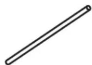
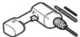
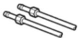
TOOLS YOU MAY NEED
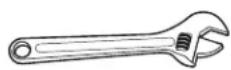
Adjustable Wrench
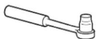
3/8" Socket Ratchet/Driver
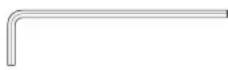
1/8", 3/32", 1/4" & 5/32"
Allen (Hex) Wrenches
Phillips-Head Screwdriver


1/4" Outer Diameter Compression Nut and Ferrule (sleeve)
Pencil
Level
1/8" Drill Bit and Electric or Hand Drill
Flat-Head Screwdriver
1/4" Nut Driver
Tape Measure
Torx T20, T25
DIMENSIONS PGD, PGE, PJD AND PJE
NOTE: It is recommended that the floor be protected with a plastic covering throughout the installation process.
NOTE: Not recommended for installation on carpeted flooring.
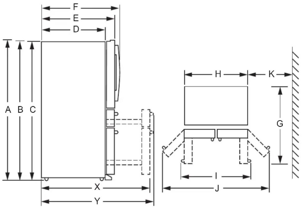
text_image
F E D A B C H K G X Y| Distance “From” to “To” | Full Depth Counter | Depth | ||
| Inches mm | Inches mm | |||
| Overall Height to Top of the Door (A) 70 1778 70 1778 | ||||
| Height to Top of Hinge Cover (B) | 69 3/4 | 1772 | 69 3/4 | 1772 |
| Height to Top of Case (C) | 68 5/8 | 1742 | 68 5/8 | 1742 |
| Case Depth without Door (D) | 29 7/16 | 747 | 24 7/16 | 620 |
| Case Depth with Door, less Door Handle (E) | 34 1/4 | 870 | 29 1/4 | 743 |
| Case Depth with Door and Handle (F) | 36 7/16 | 925 | 31 7/16 | 798 |
| Depth with Refrigerator Door Open 90° (G) | 48 3/8 | 1228 | 43 3/8 | 1101 |
| Width (H) | 35 5/8 | 905 | 35 5/8 | 905 |
| Width with Door Open 90°, with Handle (I) | 44 3/8 | 1127 | 44 3/8 | 1127 |
| Width with Doors Fully Open (J) | 60 3/8 | 1533 | 60 3/8 | 1533 |
| Min. Distance Between Case and Wall to Allow Doors to Fully Open (K) | 13 3/4 | 349 | 13 3/4 | 349 |
| Depth with Freezer Door Completely Open, without Handle (X) | 53 1/2 | 1360 46 | 1168 | |
| Depth with Freezer Door Completely Open, with Handle (Y) | 55 3/4 | 1415 | 48 1/6 | 1223 |
DIMENSIONS - PAD and PHD Models
NOTE: It is recommended that the floor be protected with a plastic covering throughout the installation process.
NOTE: Not recommended for installation on carpeted flooring.
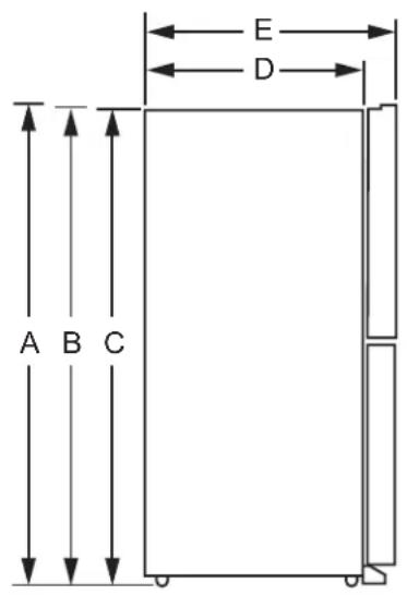
text_image
A B C E D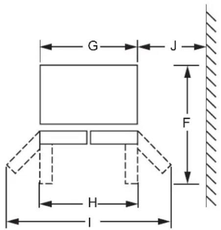
text_image
G J F H I| Description Full Depth Counter Depth | ||
| Overall Height to Top of the Door (A) 70" (1775 mm) 70" (1775 mm) | ||
| Height to Top of Hinge Cover (B) 69-13/16" (1772 mm) 69-13/16" (1772 mm) | ||
| Height to Top of Case (C) 68-13/16" (1772 mm) 68-13/16" (1772 mm) | ||
| Case Depth without Door (D) 29-3/4" (755 mm) | 24-3/4" (628 mm) | |
| Case Depth with Door (E) 34-1/4" (870 mm) 29-1/4" (743 mm) | ||
| Depth with Refrigerator Door Open 90° (F) 48-3/8" (1228 mm) 43-3/8" (1101 mm) | ||
| Width (G) 35-3/4" (908 mm) 35-3/4" (908 mm) | ||
| Width with Door Open 90° (H) | 44-7/8" (1140 mm) | 44-7/8" (1140 mm) |
| Width with Doors Fully Open (I) | 60-1/8" (1527 mm) | 60-1/8" (1527 mm) |
| Min. Distance Between Case and Wall to Allow Doors to Fully Open (J) | 13" (330 mm) | 13" (330 mm) |
MOVING THE REFRIGERATOR
- Using the chart below determine if the width of your passageway can accommodate the depth of the refrigerator. Ensure you have clearance to prevent damage to the refrigerator before safely moving it to the final location.
- If passageways are large enough to accommodate the refrigerator without removing the handles skip to Step 6. Leave tape, film and all packaging on doors until the refrigerator is in the final location.
- NOTE: Use a padded hand truck or moving straps to move this refrigerator. Place the refrigerator on the hand truck with a side against the truck. We strongly recommend that two people move and complete this installation.
| If your opening is less than the following dimensions, remove door parts in order until dimension is less than the opening. | ||
| PGD, PGE, PAD PJD, | PJE, PHD | |
| Fully Assembled 37-1/8' | (943 mm) 32-1/8" (816 mm) | |
| Remove Handles 34-9/16' | (878 mm) 29-9/16" (751 mm) | |
| Remove Doors 32-1/4" | (819 mm) 27-1/4" (692 mm) | |
| Remove Center Hinge 29 | 3/4" (755 mm) 24-3/4" | (628 mm) |
REFRIGERATOR LOCATION
■ Do not install the refrigerator where the temperature will go below 60^ F ( 16^ C) because it will not run often enough to maintain proper temperatures.
■ Do not install the refrigerator where the temperature will go above 100^ F ( 37^ C) because it will not perform properly.
■ Do not install the refrigerator in a location exposed to water (rain, etc.) or direct sunlight.
■ Install it on a floor strong enough to support it fully loaded.
CLEARANCES
Allow the following clearances for ease of installation, proper air circulation and plumbing and electrical connections. Sides 1/8" (3 mm)
Top 1" (25 mm) Cabinet/Hinge Cover Back 2" (50 mm)
REMOVING THE REFRIGERATOR DOORS
■ IMPORTANT NOTE: This refrigerator is 37-1/8" (943 mm) deep (refer to chart on previous page). Doors and passageways leading to the installation location must be at least 37-1/8" (943 mm) wide in order to leave the doors and handles attached to the refrigerator while transporting it into the installation location. If passageways are less than 37-1/8" (943 mm), the refrigerator doors and handles can easily be scratched and damaged. The top cap and doors can be removed to allow the refrigerator to be safely moved indoors. If passageways are less than 34-9/16" (878 mm), start with Step 1.
■ If it is not necessary to remove doors, skip to Step 11. Leave tape and all packaging on doors until the refrigerator is in the final location.
■ NOTE: Use a padded hand truck to move this refrigerator. Place the refrigerator on the hand truck with a side against the truck. We strongly recommend that TWO PEOPLE move and complete this installation.
INSTALLING THE REFRIGERATOR

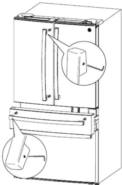
REFRIGERATOR AND FREEZER HANDLE INSTALLATION
Before You Start....
■ To avoid injury, wear closed-toe shoes when installing the handles.
■ While installing the handle, grasp the handle firmly to ensure it does not fall or scratch the appliance's finish.
■ IMPORTANT: To make sure the handles are accurately installed, please review the instructions and graphics before you begin installation.
■ IMPORTANT: Do not use power tools to tighten set screws.
Tools Provided:
■ 1/8" hex key
Handle appearance may vary based on model; however, the installation process is the same.
- Remove any protective film from the door or drawer fronts before installing handles (if applicable).
- Remove handle from packaging and locate the provided 1/8" hex key.
- Place the handle over the mounting fasteners until it is flush against the surface of the door.
- Tighten both set screws in the handle end caps by turning the 1/8" hex key clockwise until the handle will not hang loose or fall from its mounting. Do not fully tighten yet.
5. IMPORTANT:
Hold the handle firmly against the door, make sure there are no gaps between the handle end caps and the door, and fully tighten the set screws.
To remove the handles, reverse the installation process.
natural_image
Technical line drawing of a refrigerator with internal components and two magnified views of the door (no text or symbols)
REFRIGERATOR HANDLE INSTALLATION FOR DOOR-IN- DOOR MODELS ONLY
Handle appearance may vary based on model; however, the installation process is the same.
-
Remove any protective film from the door or drawer fronts before installing handles (if applicable). Do not remove the tape that secures the inner door to the outer door until after the handle is installed.
-
Remove handle from packaging and locate the provided 1/8" hex key.
-
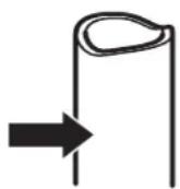
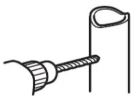
Align the lever with the opening on the outer door. Make sure the hook is pointed up.
-
Insert the latch lever into the opening and place the handle over the mounting fasteners until it is flush against the surface of the door.
-
Tighten both set screws in the handle end caps by turning the 1/8" hex key clockwise until the handle will not hang loose or fall from its mounting. Do not fully tighten yet.
-
IMPORTANT: Hold the handle firmly against the door, make sure there are no gaps between the handle end caps and the door, and fully tighten the set screws.
To remove the handles, reverse the installation process.
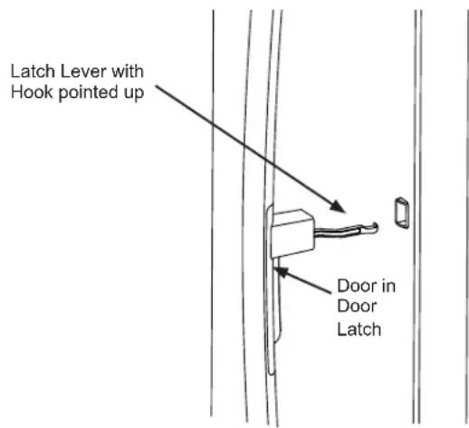
text_image
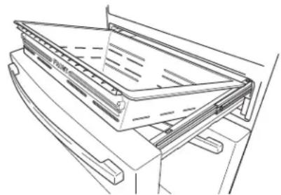
Latch Lever with Hook pointed up Door in Door LatchINSTALLING THE REFRIGERATOR (Cont.)
③ REMOVE LEFT-HAND DOOR
WARNING
Follow all steps for removing
and reinstalling the door. Failure to follow these instructions, leaving off parts, or overtightening screws, can lead to the door falling off and result in injury and property damage.
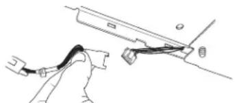
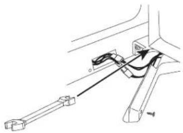
- Remove the two water tubes from the connectors on the back of the case.
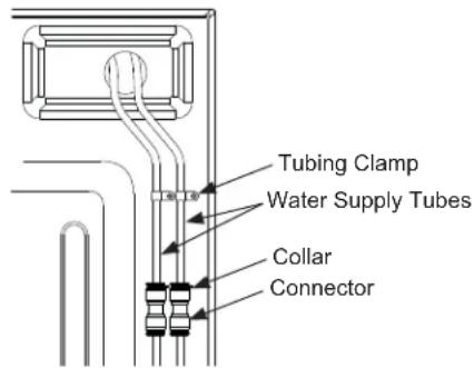
text_image
Tubing Clamp Water Supply Tubes Collar Connector- Loosen and remove the tubing clamp(s) which holds the water supply tube to the back of the refrigerator.
- Remove the black collar from water supply tube connector at the top right back of the refrigerator.
-
Press the white flange down and separate the water supply line from the connector.
-
Remove the left hinge cover by removing 2 hinge cover screws with a Phillips head screwdriver and lifting from the left side. Disconnect electrical connectors and pull the water supply tube through the case.
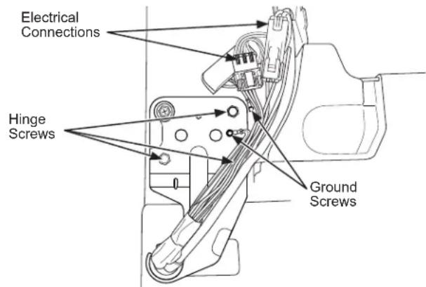
text_image
Electrical Connections Hinge Screws Ground Screws- Securely tape the door shut with masking tape or have a second person support the door.
- Remove screws holding hinge with a 5/16" socket. Lift hinge from refrigerator and door.
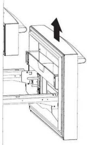
③ REMOVE LEFT-HAND DOOR (cont.)
For proper installation later, please follow these next steps carefully:
■ Remove the tape keeping the door as straight as possible, then lift up to remove.
CAUTION
Lifting Hazard.
A single person lift could cause injury. Gain assistance when handling, moving, or lifting refrigerator doors.
4 REMOVE RIGHT-HAND DOOR
■ Remove right hinge cover.
- Securely tape the door shut with masking tape or have a second person support the door.
■ Remove screws holding hinge with a 5/16" socket. Lift hinge from refrigerator and door.
For proper installation later, please follow these next steps carefully:
■ Remove the tape keeping the door as straight as possible, then lift up to remove.
CAUTION
Lifting Hazard.
A single person lift could cause injury. Gain assistance when handling, moving, or lifting refrigerator doors.
To reassemble doors, reverse removal steps.
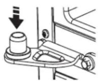
⑤ REMOVE CENTER HINGE (if necessary)
Remove screws that secure hinge to the cabinet. Inner screws need a 5/16" socket. Outer screw needs a Phillips #2.
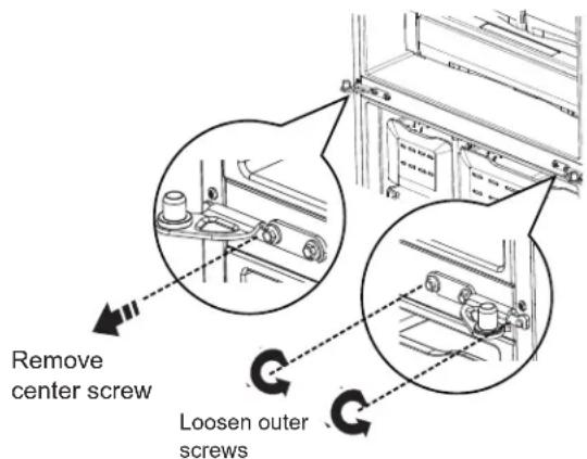
text_image
Remove center screw Loosen outer screwsINSTALLING THE REFRIGERATOR (Cont.)
⑥ REINSTALLING THE LEFT-HAND AND RIGHT-HAND DOORS
WARNING
Follow all steps for removing
and reinstalling the door. Failure to follow these instructions, leaving off parts, or overtightening screws, can lead to the door falling off and result in injury and property damage.
- Reinstall center hinge first and torque the 14 " screw to 65 in-lbs (7.34 N-m) and small screw to 25 in-lbs (2.82 N-m). Rotating the screw by 1/3 turn after it is flush with mating surface will achieve these torques.
- Lower the refrigerator door onto the center hinge.
- Securely tape the door shut with masking tape or have a second person support the door.
- Reinstallation is the reverse of the removal instructions.
- Be sure to reinstall the ground wire and strain relief to the top hinge.
- Reinstall hinge cover. NOTE: Ensure wires are not pinched or under screw bosses before tightening screws.
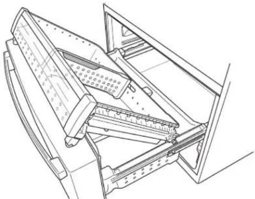
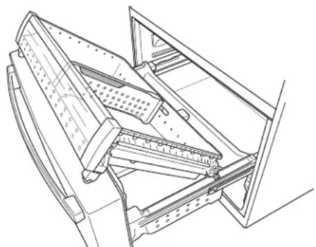
7 REMOVING CONVERTIBLE DRAWER
- Remove the convertible drawer basket by lifting while rotating the basket upward.
natural_image
Technical line drawing of a mechanical assembly or frame structure (no text or symbols)- Disconnect the control connection for the convertible drawer.
- Using a flat-head screwdriver, remove cover over electric connectors on inside right of the drawer frame. The cover hooks through the drawer frame toward the inside of the refrigerator.
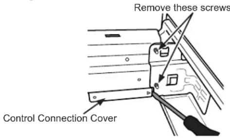
text_image
Remove these screws Control Connection Cover- Press the tab in the center of the connector to separate.
natural_image
Line drawing of a hand holding a tool near a mechanical component (no text or symbols)- Remove 2 screws from each side of the frame with a 5/16" socket.
- Remove door by lifting off hooks.
INSTALLING THE REFRIGERATOR (Cont.)
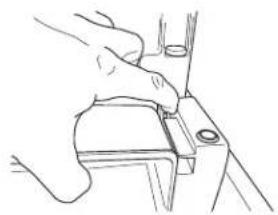
8 REMOVE LOWER FREEZER BASKET
■ Pull the top freezer drawer basket forward until it is out of the track in the freezer compartment. Lift, while rotating the basket upward to remove.
natural_image
Technical line drawing of a mechanical device with no visible text or symbols■ Press the tab on the right side bracket to remove the freezer door bin.
natural_image
Line drawing of a hand using a tool to adjust or install a mechanical component (no text or symbols)■ Pull the freezer drawer to full extension.
■ Lift the bottom freezer drawer basket slightly back, then up and out of the drawer.
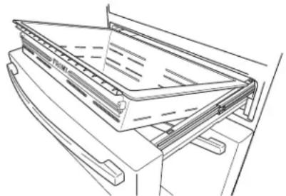
9 REMOVE THE FREEZER DRAWER
- Pull the freezer drawer open to full extension.
- Remove two screw from each side of the frame with a 5/16" socket.
natural_image
Technical line drawing of a mechanical assembly with no visible text or symbolsCAUTION
Lifting Hazard
Freezer door is heavy Use both hands to secure the door before lifting.
- Remove the door by lifting off hooks.
natural_image
Technical line drawing of a mechanical assembly with an arrow indicating direction (no text or symbols present)INSTALLING THE REFRIGERATOR (Cont.)

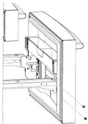
REMOVE LOWER LEFT-HAND DOOR (on some models)
WARNING
Follow all steps for removing and reinstalling the door. Failure to follow these instructions, leaving off parts, or overtightening screws, can lead to the door falling off and result in injury and property damage.
- Securely tape the door shut with masking tape or have a second person support the door.
- Remove the center hinge with a 5/16" socket and Phillips head screwdriver.
natural_image
Technical line drawing of a mechanical assembly with no visible text or symbols- Remove the tape keeping the door as straight as possible, then lift up to remove.
CAUTION
Lifting Hazard.
A single person lift could cause injury. Gain assistance when handling, moving, or lifting refrigerator doors.

REMOVE LOWER RIGHT-HAND DOOR (on some models)
- Open lower right-hand door 90°.
- Remove lower hinge cover by removing Phillips head screw and unsnapping cover from hinge.
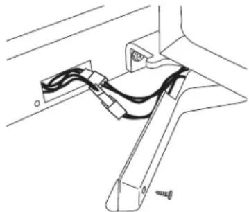
natural_image
Technical line drawing of a mechanical assembly with no visible text or symbols- Disconnect 2 harnesses.
- Securely tape the door shut with masking tape or have a second person support the door.
- Remove the center hinge with a 5/16" socket and Phillips head screwdriver.
natural_image
Technical line drawing of a mechanical bracket assembly (no text or symbols)- Remove the tape keeping the door as straight as possible, then lift up to remove.
CAUTION
Lifting Hazard
Freezer door is heavy Use both hands to secure the door before lifting.
- Pull the lower basket slide mechanism to full extension with both hands.
- Lift the freezer door and align the hooks with the notches on the slide mechanisms. NOTE: Place one side in first, then align the other side.
- Replace the attachment screws and torque the screws to 65 in-lb (7.34 N-m).
To reassemble doors, reverse removal steps. Be careful wires pass through bottom hight-hand hinge.
INSTALLING THE REFRIGERATOR (Cont.)
12 REMOVE LOWER HINGE (if necessary) (on some models)
Remove screws that secure hinge to the cabinet. Inner screws need a 5/16" socket. Outer screw needs a Phillips #2."
13 RE-INSTALL CONVERTIBLE DRAWER
To reassemble doors, reverse removal steps. Convertible drawer basket will be loose if re-installed backwards. Look for "FRONT" emboss to help with re-installation.
natural_image
Technical line drawing of a mechanical assembly or frame structure (no text or symbols)14 REPLACE FREEZER DRAWER
CAUTION
Lifting Hazard
Freezer door is heavy Use both hands to secure the door before lifting.
- Pull the lower basket slide mechanism to full extension with both hands.
- Lift the freezer door and align the hooks with the notches on the slide mechanisms. NOTE: Place one side in first, then align the other side.

text_image
Freezer door hook and slide mechanism notch- Replace the attachment screws and torque the screws to 65 in-lb (7.34 N-m).
15 RE-INSTALL FREEZER BASKETS
- Re-install lower freezer basket
- Re-install top freezer drawer by placing the drawer wheels onto the top of the tracks on the side of the freezer walls. The front wheels on the freezer drawer should be on top of the bottom basket.
natural_image
Technical line drawing of a mechanical assembly with no visible text or symbols- Check for smooth operation of baskets.
16 REINSTALL LOWER LEFT AND RIGHT-HAND DOORS (on some models)
WARNING
Follow all steps for removing
and reinstalling the door. Failure to follow these instructions, leaving off parts, or overtightening screws, can lead to the door falling off and result in injury and property damage.
CAUTION
Lifting Hazard
A single person lift could cause injury. Gain assistance when handling, moving, or lifting refrigerator doors.
- Reinstall lower hinges first (if necessary) and torque the 5/16" screws to 65 in-lb (7.35 N-m) and small screw to 25 in-lbs (2.82 N-m). Rotating the screw by 1/3 turn after it is flush with mating surface will achieve these torques.
-
With the door at 90^ to the front of the case, lower the refrigerator door onto the lower hinge, carefully pulling the harness through the right-hand hinge. Close the door and tape closed.
-
Reinstall the center hinge per step #1 above.
-
Remove the tape.
-
Open the lower right-hand door 90°.
-
Connect the two harnesses.
-
Replace both lower hinge covers (if necessary).
INSTALLING THE REFRIGERATOR (Cont.)
17 CONNECTING THE REFRIGERATOR TO THE HOUSE WATER LINE
A cold water supply is required for automatic ice maker operation. If there is not a cold water supply, you will need to provide one. See Installing the Water Line section.
NOTES:
- Before making the connection to the refrigerator, be sure the refrigerator power cord is not plugged into the wall outlet.
- If your refrigerator does not have a water filter, we recommend installing one if your water supply has sand or particles that could clog the screen of the refrigerator's water valve. Install it in the water line near the refrigerator. If using SmartConnect™ Refrigerator Tubing Kit, you will need an additional tube (WX08X10002) to connect the filter. Do not cut plastic tube to install filter.
- Before connecting the water line to the house, purge the house line for at least 2 minutes.
A If you are using copper tubing, place a compression nut and ferrule (sleeve) onto the end of the tubing coming from the house cold water supply.
WARNING

Electrical Shock Hazard.
Attach tubing clamp using existing hole only. DO NOT drill into the refrigerator.
If you are using the SmartConnect™ tubing, the nuts are already assembled to the tubing.
B If you are using copper tubing, insert the end of the tubing into the refrigerator connection, at the back of the refrigerator, as far as possible. While holding the tubing, tighten the fitting.
If you are using SmartConnect™ tubing, insert the molded end of the tubing into the refrigerator connection, at the back of the refrigerator, and tighten the compression nut until it is hand tight. Then tighten one additional turn with a wrench. Over tightening may cause leaks.
C Fasten the tubing into the clamp provided to hold it in position. You may need to pry open the clamp.
WARNING
Connect to potable water supply only. A cold water supply is required for automatic icemaker operation. The water pressure must be between 40 and 120 psi (275-827 kilopascals)
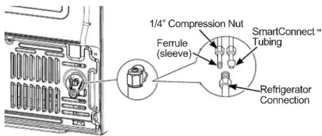
text_image
1/4" Compression Nut Ferrule (sleeve) SmartConnect™ Tubing Refrigerator ConnectionINSTALLING THE REFRIGERATOR (Cont.)
18 TURN ON THE WATER SUPPLY
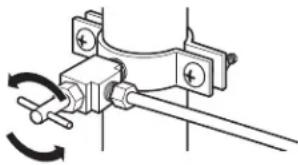
natural_image
Mechanical clamp mechanism diagram showing rotational motion (no text or symbols)Turn the water on at the shutoff valve (house water supply) and check for any leaks.
19 PLUG IN THE REFRIGERATOR
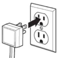
natural_image
Simple line drawing of an electrical outlet with a plug inserted, showing two socket terminals (no text or symbols)See the grounding information attached to the power cord.
The leveling legs have 2 purposes:
- Leveling legs adjust so the refrigerator is firmly positioned on the floor and does not wobble.
- Leveling legs serve as a stabilizing brake to hold the refrigerator securely in position during operation and cleaning. The leveling legs also prevent the refrigerator from tipping.
■ Turn the leveling legs clockwise to raise the refrigerator, counterclockwise to lower it.
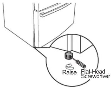
text_image
Raise Flat-Head ScrewdriverNOTICE: To avoid possible property damage, the leveling legs must be firmly touching the floor.
Installation Instructions
INSTALLING THE REFRIGERATOR (Cont.)
21 LEVEL THE REFRIGERATOR DOORS
Remember a level refrigerator is necessary for getting the doors perfectly even. If you need help, review the previous section on leveling the refrigerator.
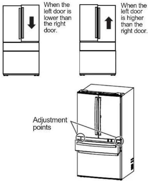
text_image
When the left door is lower than the right door. When the left door is higher than the right door. Adjustment pointsFor 4 door models:
Using a 14 " open end wrench or flat-head screwdriver, turn the slotted wheel to adjust doors up or down.
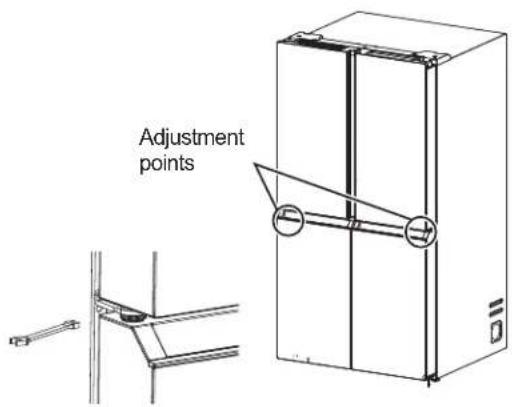
text_image
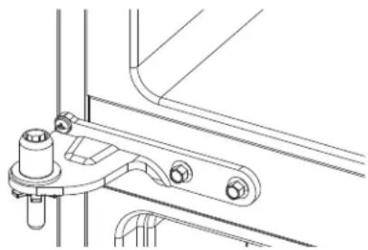
Adjustment pointsTo adjust the height of the lower doors:
■ Remove the left-hand and right-hand hinge covers with a Phillips head screwdriver, then use a 14mm open end wrench to adjust the doors up or down.
natural_image
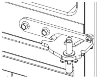
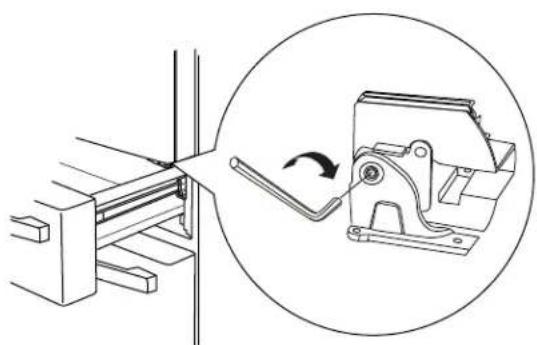
Technical line drawing of a mechanical assembly with no visible text or symbolsFor 2 drawer models:
- Access the hinge screws by opening the convertible drawer.
- Insert 1/4" Allen wrench into the shaft of the center hinge.
- Adjust the height by turning clockwise or counterclockwise. When you turn counterclockwise, the door will move up.
natural_image
Technical diagram showing a mechanical clamp or bracket assembly with an inset close-up of the component (no text or symbols present)INSTALLING THE REFRIGERATOR (Cont.)
Four Door Models
text_image
A B C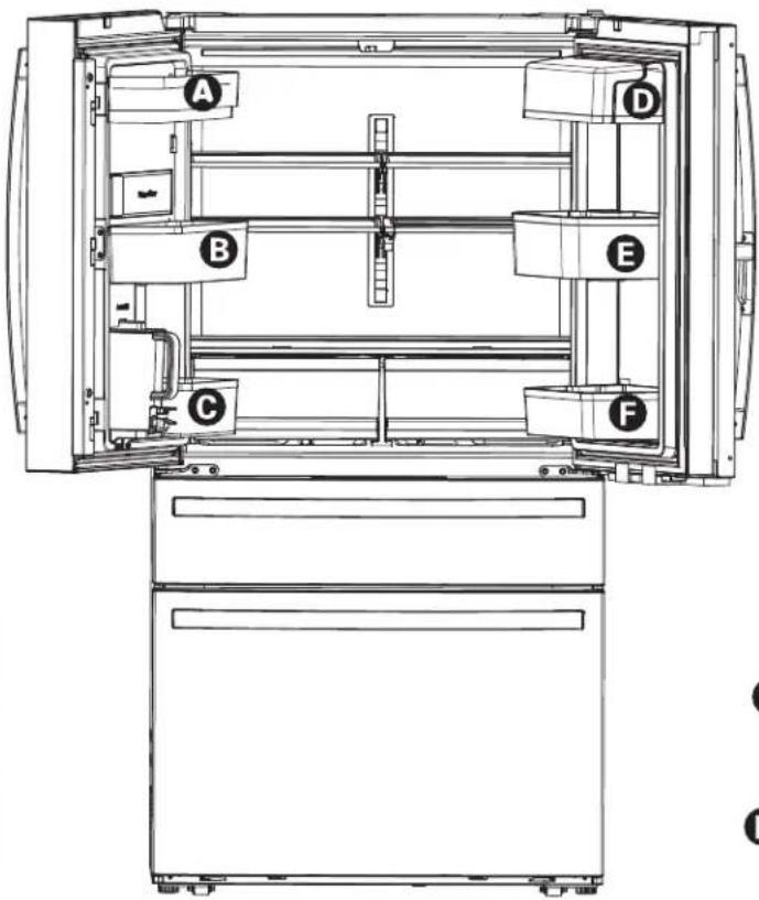
text_image
A B C D E F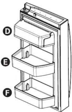
natural_image
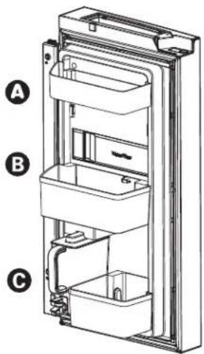
Technical line drawing of a refrigerator with labeled parts (D, E, F), showing internal compartments and casing structure (no text or symbols beyond labels)To place bins into doors:
1 Match your bin with the letter shown. Position the bins over the bin locator and push forward until inserted fully.
2 Push bin down until locked into position.
natural_image
Line drawing of a bathroom sink with fixtures and door (no text or symbols)Installation Instructions
INSTALLING THE REFRIGERATOR (Cont.)
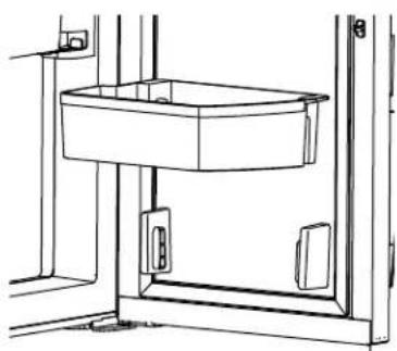
Profile Four Door, Door-in-Door Models
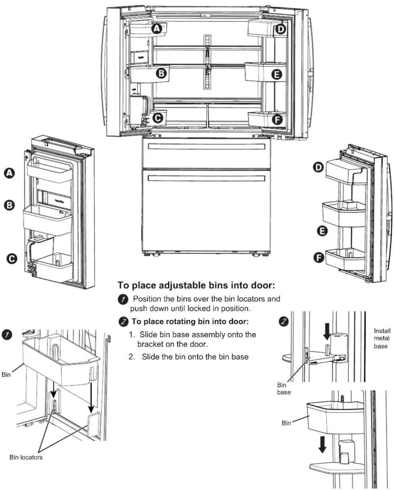
To place adjustable bins into door:
7 Position the bins over the bin locators and push down until locked in position.
2 To place rotating bin into door:
- Slide bin base assembly onto the bracket on the door.
- Slide the bin onto the bin base
INSTALLING THE REFRIGERATOR (Cont.)
PAD and PHD Models
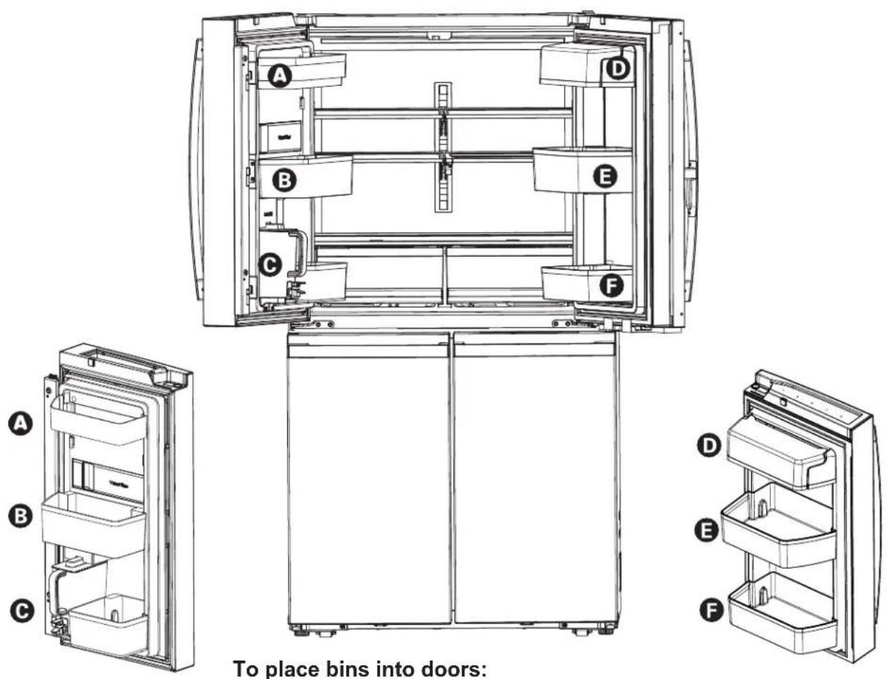
To place bins into doors:
1 Match your bin with the letter shown. Position the bins over the bin locator and push forward until inserted fully.
2 Push bin down until locked into position.
natural_image
Pure mechanical assembly diagram showing two upward arrows indicating motion or force direction (no text or symbols)INSTALLING THE WATER LINE
BEFORE YOU BEGIN
Recommended copper water supply kits are WX8X2, WX8X3 or WX8X4, depending on the amount of tubing you need. Approved plastic water supply lines are SmartConnect™ Refrigerator Tubing (WX08X10006, WX08X10015 and WX08X10025).
When connecting your refrigerator to a GE Appliances Reverse Osmosis Water System, the only approved installation is with a GE Appliances RVKit. For other reverse osmosis water systems, follow the manufacturer's recommendations.
If the water supply to the refrigerator is from a Reverse Osmosis (RO) Water Filtration System AND the refrigerator also has a water filter, use the refrigerator's filter bypass plug. Using the refrigerator's water filtration cartridge in conjunction with the RO water filter can result in hollow ice cubes. Some models do not come equipped with the filter bypass plug. To obtain a free bypass plug, call 1.800.GECARES and request WR17X33825 filter bypass plug. In Canada, call 800.561.3344.
This water line installation is not warranted by the refrigerator or ice maker manufacturer. Follow these instructions carefully to minimize the risk of expensive water damage.
Water hammer (water banging in the pipes) in house plumbing can cause damage to refrigerator parts and lead to water leakage or flooding. Call a qualified plumber to correct water hammer before installing the water supply line to the refrigerator.
To prevent burns and product damage, do not hook up the water line to the hot water line.
If the refrigerator is operated before the water connection is made to the ice maker, see Controls section on page 8 to turn ice maker off.
Do not install the ice maker tubing in areas where temperatures fall below freezing.
When using any electrical device (such as a power drill) during installation, be sure the device is double insulated or grounded in a manner to prevent the hazard of electric shock, or is battery powered.
All installations must be in accordance with local plumbing code requirements.
WHAT YOU WILL NEED
- Copper or SmartConnect" Refrigerator Tubing kit, 1/4" outer diameter to connect the refrigerator to the water supply. If using copper, be sure both ends of the tubing are cut square.
To determine how much tubing you need: measure the distance from the water valve on the back of the refrigerator to the water supply pipe. Be sure there is sufficient extra tubing to allow the refrigerator to move out from the wall after installation.
SmartConnect™ Refrigerator Tubing Kits are available in the following lengths:
8' (2.4 m) - WX08X10006
15' (4.6 m) - WX08X10015
25' (7.6 m) - WX08X10025
WARNING
Connect to potable water supply only.
A cold water supply is required for automatic icemaker operation. The water pressure must be between 40 and 120 psi (275-827 kilopascals)
INSTALLING THE WATER LINE (Cont.)
WHAT YOU WILL NEED (Cont.)
NOTE: The only Café approved plastic tubing is that supplied in SmartConnect™ Refrigerator Tubing kits. Do not use any other plastic water supply line because the line is under pressure at all times. Certain types of plastic will crack or rupture with age and cause water damage to your home.
- A GE Appliances water supply kit (containing tubing, shutoff valve and fittings listed below) is available at extra cost from your dealer or from Parts and Accessories, 877-959-8688 (in Canada 1.800.661.1616).
- A cold water supply. The water pressure must be between 20 and 120 p.s.i. (1.4–8.1 bar).
- Power drill.
- 1/2" or adjustable wrench.
• Straight and Phillips blade screwdriver.
- Two 1/4" outer diameter compression nuts and 2 ferrules (sleeves)—to connect the copper tubing to the shutoff valve and the refrigerator water valve.
OR - If you are using a SmartConnect™ Refrigerator Tubing kit, the necessary fittings are preassembled to the tubing.
- If your existing copper water line has a flared fitting at the end, you will need an adapter (available at plumbing supply stores) to connect the water line to the refrigerator OR you can cut off the flared fitting with a tube cutter and then use a compression fitting. Do not cut formed end from SmartConnect™ Refrigerator tubing.
- Shutoff valve to connect to the cold water line. The shutoff valve should have a water inlet with a minimum inside diameter of 5/32" at the point of connection to the COLD WATER LINE. Saddle-type shutoff valves are included in many water supply kits. Before purchasing, make sure a saddle-type valve complies with your local plumbing codes.
Install the shutoff valve on the nearest frequently used drinking water line.
① SHUT OFF THE MAIN WATER SUPPLY
Turn on the nearest faucet long enough to clear the line of water.
② CHOOSE THE VALVE LOCATION
Choose a location for the valve that is easily accessible. It is best to connect into the side of a vertical water pipe. When it is necessary to connect into a horizontal water pipe, make the connection to the top or side, rather than at the bottom, to avoid drawing off any sediment from the water pipe.
③ DRILL THE HOLE FOR THE VALVE
Drill a 1/4" hole in the water pipe (even if using a self-piercing valve), using a sharp bit. Remove any burrs resulting from drilling the hole in the pipe.
Take care not to allow water to drain into the drill.
Failure to drill a 1/4" hole may result in reduced ice production or smaller cubes.
natural_image
Simple line drawing of a mechanical component with a threaded end and curved top (no text or symbols)INSTALLING THE WATER LINE (Cont.)
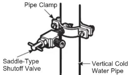
4 FASTEN THE SHUTOFF VALVE
Fasten the shutoff valve to the cold water pipe with the pipe clamp.
text_image
Pipe Clamp Saddle-Type Shutoff Valve Vertical Cold Water PipeNOTE: Commonwealth of Massachusetts Plumbing Codes 248CMR shall be adhered to. Saddle valves are illegal and use is not permitted in Massachusetts. Consult with your licensed plumber.
⑤ TIGHTEN THE PIPE CLAMP
Tighten the clamp screws until the sealing washer begins to swell.
NOTE: Do not over tighten or you may crush the tubing.
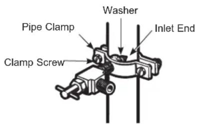
text_image
Pipe Clamp Washer Inlet End Clamp Screw6 ROUTE THE TUBING
Route the tubing between the cold water line and the refrigerator.
Route the tubing through a hole drilled in the wall or floor (behind the refrigerator or adjacent base cabinet) as close to the wall as possible.
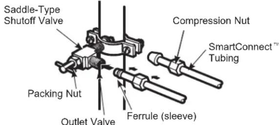
7 CONNECT THE TUBING TO THE VALVE
Place the compression nut and ferrule (sleeve) for copper tubing onto the end of the tubing and connect it to the shutoff valve.
Make sure the tubing is fully inserted into the valve. Tighten the compression nut securely.
For plastic tubing from a SmartConnect™ Refrigerator Tubing kit, insert the molded end of the tubing into the shutoff valve and tighten compression nut until it is hand tight, then tighten one additional turn with a wrench. Over tightening may cause leaks.
text_image
Saddle-Type Shutoff Valve Packing Nut Outlet Valve Compression Nut SmartConnect™ Tubing Ferrule (sleeve)NOTE: Commonwealth of Massachusetts Plumbing Codes 248CMR shall be adhered to. Saddle valves are illegal and use is not permitted in Massachusetts. Consult with your licensed plumber.
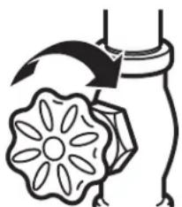
8 FLUSH OUT THE TUBIN
Turn the main water supply on and flush out the tubing until the water is clear.
Shut the water off at the water valve after about one quart (1 liter), or 2 minutes, of water has been flushed through the tubing.
natural_image
Simple line drawing of a flower with a curved arrow above it, no text or symbols present.To complete the installation of the refrigerator, go back to Step 12 in Installing the Refrigerator.
Newer refrigerators sound different from older refrigerators.
Modern refrigerators have more features and use newer technology.
Do you hear what I hear? These conditions are normal.
HUMMM...

WHOOSH...
■ The new high efficiency compressor may run faster and longer than your old refrigerator and you may hear a high-pitched hum or pulsating sound while it is operating.
■ You may hear a whooshing sound when the doors close. This is due to pressure equalizing within the refrigerator.
■ After dispensing ice, a motor will close the ice chute to keep warn room air from entering the ice bucket, maintaining ice at a freezing temperature.
The hum of the motor closing the ice chute is normal, shortly after dispensing ice.
WHIR!

- You may hear the fans spinning at high speeds. This happens when the refrigerator is first plugged in, when the doors are opened frequently or when a large amount of food is added to the refrigerator or freezer compartments. The fans are helping to maintain the correct temperatures.
■ The fans change speeds in order to provide optimal cooling and energy savings.
CLICKS, POPS, CRACKS and SNAPS
■ You may hear cracking or popping sounds when the refrigerator is first plugged in. This happens as the refrigerator cools to the correct temperature.
■ The compressor may cause a clicking or chirping sound when attempting to restart (this could take up to 5 minutes).
■ Expansion and contraction of cooling coils during and after defrost can cause a cracking or popping sound.
■ On models with an icemaker, after an ice making cycle, you may hear the ice cubes dropping into the ice bucket.
■ After dispensing ice, a motor will close the ice chute to keep warm room air from entering the ice bucket, maintaining ice at a freezing temperature.
WATER SOUNDS

■ The flow of refrigerant through the cooling coils may make a gurgling noise like boiling water.
■ Water dropping on the defrost heater can cause a sizzling, popping or buzzing sound during the defrost cycle.
■ A water dripping noise may occur during the defrost cycle as ice melts from the evaporator and flows into the drain pan.
■ Closing the door may cause a gurgling sound due to pressure equalization.
If the AutoFill pitcher is not full it fills automatically approximately 5 seconds after the door is closed. It is normal to hear water rushing for up to several minutes while the pitcher is filling.
START UP COOLING
It can take up to 24 hours for the refrigerator temperatures to reach the set temperatures. During that time refrigerator and freezer door openings should be minimized.
Troubleshooting Tips... Before you call for service
Save time and money! Review the charts on the following pages first and you may not need to schedule service.
| Problem Possible Causes What to Do | ||
| Not filtering Filter bypass installed. | Install correct water filter. | |
| Leak Detected at Filter Water filter | leaking or needs replacing. | Replace water filter or install filter bypass plug. |
| Water filter indicator light remains lit after replacing filter | Water filter or bypass plug installed backward or wrong filter installed. | Remove filter or bypass plug, rotate it 180 degrees and reinstall. |
| Handle is loose/handle has a gap. | Handle needs adjusting See Installing | the Refrigerator section for detailed instructions. |
| Refrigerator beeping The door alarm | arm is beeping from a door being ajar or open. | Close the door to turn off the alarm, or to disable the door alarm simultaneously hold the Fridge and Ice Maker buttons for three seconds. |
| The refrigerator has detected conditions that could indicate a water leak has occurred. | Check the AutoFill pitcher for water leaks. Removing and reinstalling the pitcher will reset the alarm. | |
| Refrigerator lights off and “SA” shown in display | Unit is in Sabbath mode | Simultaneously hold the Freezer, Ice Maker and AutoFill buttons for three seconds to exit Sabbath mode. |
| Not cooling The cooling system is off See Controls. | ||
| Freezer or Refrigerator temperature not changing | User interface on convertible door is for convertible zone only. | Use user interface on top of refrigerator to select desired freezer or refrigerator temperatures |
| No water or ice cube production | Supply line or shutoff valve is clogged | Call a plumber |
| Water filter is clogged Replace filter | cartridge or remove filter and install bypass plug* | |
| Filter cartridge not properly installed | Remove and reinstall filter cartridge, being certain that it locks in place. | |
| Icemaker is turned off Check that the icemaker is turned on. See Controls | ||
| Ice cubes are cloudy, fused together, shrunken or stale tasting | Extended periods of low ice usage For large ice buckets with minimal ice usage, periodically empty the ice bucket or turn the icemaker off. | |
| No water in AutoFill Pitcher AutoFill Pitcher feature isn't turned on | Press the AutoFill Pitcher button on the controls at the top of the fresh food compartment. The LED under the button indicates that the feature is on. | |
| AutoFill Pitcher is not fully seated in pitcher tray | ||
| Refrigerator water line not connected to house supply line or house water valve is closed | ||
*Some models do not come equipped with the filter bypass plug. To obtain a free bypass plug, call 1.800.GECARES and request WR17X33825 filter bypass plug. In Canada, call 800.561.3344.
Troubleshooting Tips... Before you call for service
| Problem Possible Causes What to | Do | ||
| Freezer cooling, refrigerator not cooling | Normal, when refrigerator first plugged in or after extended power outage | Wait 24 hours for temperature in both compartments to reach selected temperatures. | |
| My refrigerator door squeaks Diminished lubricant because of accidental cleaning of the lubricant on the hinge | It is best to order GE Appliances lubricant service part number WR97X166 and apply on the hinge at specified location.It is possible to spray some non-toxic lubricant such as silicone based non-stick cooking spray, petroleum jelly or NSF approved food grade lubricants.IMPORTANT: Do not use WD-40 as it will remove any remaining grease in or around the hinge | ||
| Improper leveling Make sure the unit is leveled | |||
| If doors were removed and re-assembled during installation process, waterline and/harness under Top Hinge cover may get out of position and rub against door while door swivels. | Remove the Top Hinge cover and make sure the waterline and harness that passes through the hinge pin has been properly seated and does not touch the any of the door parts during rotation.Applying some food grade lubricant around door thimble area will also help. | ||
SERVICE
Save time and money! Review the charts on the following pages first and you may not need to schedule service.
Truth or Myth
| Truth or Myth? Answer Explanation | ||
| The refrigerator water filter may require replacement, even though the filter indicator has not turned red, or reads “Filter Expired.” | TRUE The | the water filter indicator will indicate the need to replace the water filter every six months. Water quality varies from city to city; if water flow from the dispenser slows, or ice production decreases, the water filter should be replaced, even though the filter indicator may not indicate the need for replacement. |
| The automatic ice maker in my refrigerator will produce ice when the refrigerator is plugged in to a power receptacle. | MYTH The | refrigerator must be connected to water, and the ice maker must be turned on. Make sure the ice maker is turned on, only after the water line is connected and water is turned on. The ice maker can be turned on/off from the controls and ensure the ice maker is on, as indicated on the refrigerator control panel. See Automatic Ice Maker section in the full owner's manual available online. |
| I will never see frost inside the freezer compartment. | MYTH Frost | inside the freezer typically indicates that the door is not properly sealed, or has been left open. If frost is found, clear the frost using a plastic spatula and towel, then check to ensure that no food packages or containers are preventing the freezer door from closing. Check the refrigerator control panel to ensure the door alarm is on. |
| I can use the water filter bypass plug to determine if the filter requires replacement. | TRUE Decrease in flow from the water dispenser, or decreased ice production, may indicate the need to replace the water filter. Install the water filter bypass plug (provided with the refrigerator on some models*), and check flow from the dispenser. If water flow returns to normal with the bypass plug in place, replace the water filter. | |
| The top of the refrigerator doors will always be aligned. | MYTH Several things can affect the refrigerator door alignment, including the floor the refrigerator is installed on and loading of doors. If the top of the refrigerator doors are not aligned, use a 1/4" allen wrench to adjust the right/left hand door. The adjustment screw is located on the bottom right or left hand side of the door. Refrigerator doors should be open during height adjustment. Open the freezer door to access the screw. See Step 15. | |
| Refrigerator door handles can be easily tightened. | TRUE If door handles are loose or have a gap, the handle can be adjusted using a 1/8" allen wrench, on set screws located on the ends of the handles. | |
| There may be odor and taste problems with your ice. | TRUE After starting the ice maker throw away 24 hours of ice production to avoid odor and taste problems. | |
| I can make fine adjustments to the refrigerator doors to align them. | TRUE If the refrigerator doors are not aligned, use a 1/4" Allen wrench to adjust the right hand door. The adjustment screw is located on the bottom of the right door. Open the freezer door to access. See step 15. | |
SERVICE
Save time and money! Review the charts on the following pages first and you may not need to schedule service.
Truth or Myth
| Truth or Myth? Answer Explanation | ||
| Door handles should always be removed for installation. | MYTH Check chart on | reverse side of this instruction. If the doors must be removed do not remove the handles, or if the refrigerator will fit easily through the passage way opening. Adjust handles that are loose or have a gap, by adjusting 1/8" set screws on either end of handles. |
| Door removal is always required for installation. | MYTH Check chart on | reverse side of this instruction. Doors should only be removed when necessary to prevent damage from passage way or access to final location. |
| Refrigerator doors will self-close if left open. | MYTH Refrigerator doors need to be closed by consumer.A gentle bounce back is a designed feature on some models that gives a positive feedback to the user so that they can initiate and complete the door closing action. | |
| There is an adjustment to rear wheels. | MYTH | Front leveling legs are adjustable and should be used to balance the refrigerator. Leveling legs are used to make initial refrigerator door adjustment. |
| Check for leaks after all water connections are made. | TRUE While purging | the air from the water system, check all water line connections for leaks. Check the connection to the household water supply at back of refrigerator, and door water line connect. |
| Any packaging residue can be cleaned off the refrigerator using any cleaner. | MYTH Do not use wax, | polish, bleach, or other products containing chlorine on Stainless Steel panels, door handles and trim. Check this instruction under “Cleaning the Outside” for full details. |
*Some models do not come equipped with the filter bypass plug. To obtain a free bypass plug, call 1.800.GECARES and request WR17X33825 filter bypass plug. In Canada, call 1.800.561.3344.
GE Appliances Refrigerator Limited Warranty
GEAppliances.com
For US Customers, all warranty service is provided by our Factory Service Centers, or an authorized Customer Care® technician. To schedule service online, visit us at geappliances.com, or call GE Appliances at 800.GE.CARES (800.432.2737). Please have your serial number and your model number available when calling for service. In Canada, call 800.661.1616.
Servicing your refrigerator may require the use of the onboard data port for diagnostics. This gives a GE Appliances Factory Service technician the ability to quickly diagnose any issues with your appliance and helps GE Appliances improve its products by providing GE Appliances with information on your appliance. If you do not want your appliance data to be sent to GE Appliances, please advise your technician NOT to submit the data to GE Appliances at the time of service.
| For the Period of: GE Appliances Will Replace | |
| One YearFrom the date of the original purchase | Any part of the refrigerator which fails due to a defect in materials or workmanship. During the limited one-year warranty, GE Appliances will also provide, free of charge, all labor and related service to replace the defective part. |
| Thirty Days (Water filter, if included) From the original purchase date of the refrigerator | Any part of the water filter cartridge which fails due to a defect in materials or workmanship. During this limited thirty-day warranty, GE Appliances will also provide, free of charge, a replacement water filter cartridge. |
| GE PROFILETM MODELS ONLY | |
| Five YearsFrom the date of the purchase | Any part of the sealed refrigerating system (the compressor, condenser, evaporator an all connecting tubing) which fails due to a defect in materials or workmanship. During this limited five-year sealed refrigerating system warranty, GE Appliances will also provide, free of charge, all labor and related service to replace the defective part in the sealed refrigerating system. |
What GE Appliances Will Not Cover:
■ Service trips to your home to teach you how to use the product.
■ Improper installation, delivery or maintenance.
■ Failure of the product if it is abused, misused, or used for other than the intended purpose or used commercially.
■ Loss of food due to spoilage.
■ Replacement of house fuses or resetting of circuit breakers.
■ Damage to finish, such as surface rust, tarnish, or small blemishes not reported within 48 hours of delivery.
■ Replacement of the water filter cartridge, if included, due to water pressure that is outside the specified operating range or due to excessive sediment in the water supply.
■ Replacement of the light bulbs, if included, or water filter cartridge, if included, other than as noted above.
■ Damage to the product caused by accident, fire, floods or acts of God.
■ Incidental or consequential damage caused by possible defects with this appliance.
■ Product not accessible to provide required service.
■ Damage caused by a non-GE Appliances Brand water filter.
EXCLUSION OF IMPLIED WARRANTIES
Your sole and exclusive remedy is product repair as provided in this Limited Warranty. Any implied warranties, including the implied warranties of merchantability or fitness for a particular purpose, are limited to one year or the shortest period allowed by law.
For US Customers: This limited warranty is extended to the original purchaser and any succeeding owner for products purchased for home use within the USA. If the product is located in an area where service by a GE Appliances Authorized Servicer is not available, you may be responsible for a trip charge or you may be required to bring the product to an Authorized GE Appliances Service location for service. In Alaska, the limited warranty excludes the cost of shipping or service calls to your home. Some states do not allow the exclusion or limitation of incidental or consequential damages. This warranty gives you specific legal rights, and you may also have other rights which vary from state to state. To know what your legal rights are, consult your local or state consumer affairs office or your state's Attorney General.
Warrantor: GE Appliances, a Haier company
Louisville, KY 40225
For Customers in Canada: This limited warranty is extended to the original purchaser and any succeeding owner for products purchased in Canada for home use within Canada. In-home warrant service will be provided in areas where it is available and deemed reasonable by Mabe to provide.
Warrantor Canada: MC Commercial, Inc., Burlington, Ontario, L7R 5B6
XWFE Water Filter Cartridge Limited Warranty
Contact us at geapplianceparts.com, or call 800.GE.CARES.
| For the period of GE Appliances will replace | |
| Thirty DaysFrom the dateof the originalpurchase | Any part of the water filter cartridge which fails due to a defect in materialsor workmanship during this limited thirty-day warranty.* |
What GE Appliances will not cover:
■ Service trips to your home to teach you how to use the product.
■ Improper installation.
■ Failure of the product if it is abused, misused, used for other than the intended purpose or used commercially.
■ Replacement of house fuses or resetting of circuit breakers.
■ Damage to the product caused by accident, fire, floods, or acts of God.
■ Incidental or consequential damage caused by possible defects with this appliance.
EXCLUSION OF IMPLIED WARRANTIES
Your sole and exclusive remedy is part exchange as provided in this Limited Warranty. Any implied warranties, including the implied warranties of merchantability or fitness for a particular purpose, are limited to six months or the shortest period allowed by law.
This warranty is extended to the original purchaser and any succeeding owner for products purchased for home use within the USA. In Alaska, the warranty excludes the cost of shipping or service calls to your home.
Some states do not allow the exclusion or limitation of incidental or consequential damages. This warranty gives you specific legal rights, and you may also have other rights which vary from state to state. To know what your legal rights are, consult your local or state consumer affairs office or your state's Attorney General.
For Purchases Made In Iowa: This form must be signed and dated by the buyer and seller prior to the consummation of this sale.
This form should be retained on file by the seller for a minimum of two years.
Buyer:
| Name |
| Address |
| City State Zip |
| Signature Date |
Seller:
| Name |
| Address |
| City State Zip |
| Signature Date |
*If your GE Appliances part fails because of a manufacturing defect within thirty days from the date of original purchase for use, we will give you a new or, at our option, a rebuilt part without charge. Return the defective part to the parts supplier from whom it was purchased together with a copy of the "proof of purchase" for the part. If the part is defective and shows no signs of abuse, it will be exchanged. The warranty does not cover the failure of parts which are damaged while in your possession, are abused, or have been installed improperly. It does not cover the cost of returning the part to the supplier from whom it was purchased nor does it cover the cost of labor to remove or install it to diagnose the fault. It does not cover parts used in products in commercial use except in the case of air conditioning equipment. In no event shall GE Appliances be liable for consequential damages. Warrantor: GE Appliances, a Haier company
Performance Data Sheet Model: GE Appliances XWFE
■ System certified by IAPMO R&T against NSF/ANSI Standards 42, 53, 401, and P473 for the reduction of claims specified on the performance data sheet and at iapmort.org.
■ Actual performance may vary with local water conditions.
| Substance Tested for Reduction | Influent challenge concentration (mg/L) | Maximum permissible product water concentration (mg/L) | Avg % Reduction |
| Chlorine Taste and Odor 2.0 mg/L +/- 10 | % N/A 96.9 | ||
| Chloramine Taste and Odor 3.0 mg/L +/- | 10% 0.5 | 96.9 | |
| Particulate, Class I | At least 10,000/mL | N/A 91.4 | |
| Cysts | 50,000/L | N/A >99.99 | |
| Lead | 0.15 | 0.01 98.85 | |
| Mercury | 0.006 | 0.002 96.3 | |
| Asbestos | 107 to 108 fibers/ L | N/A | >99 |
| Toxaphene | 0.015 +/- 10% | 0.003 | 86.95 |
| VOC (Chloroform surrogate chemical) | 0.300 | 0.015 99.7 | |
| Alachlor | 0.050 | 0.001 > 98 | |
| Atrazine | 0.100 | 0.003 > 97 | |
| Benzene | 0.081 | 0.001 > 99 | |
| Carbofuran | 0.190 | 0.001 > 99 | |
| carbon tetrachloride 0.078 | 0.0018 98 | ||
| chlorobenzene | 0.077 | 0.001 > 99 | |
| chloropicrin | 0.015 | 0.0002 | 99 |
| 2,4-D | 0.110 | 0.0017 98 | |
| dibromochloropropane (DBCP) | 0.052 | 0.00002 | > 99 |
| α-Dichlorobenzene | 0.08 | 0.001 > 99 | |
| p-Dichlorobenzene | 0.040 | 0.001 | > 98 |
| 1,2-dichloroethane | 0.088 | 0.0048 95 | |
| 1,1-dichloroethylene | 0.083 | 0.001 > 99 | |
| cis-1,2-dichloroethylene 0.170 | 0.0005 | > 99 | |
| trans-1,2-dichloroethylene | 0.086 | 0.001 > 99 | |
| 1,2-dichloropropane | 0.080 | 0.001 > 99 | |
| cis-1,3-dichloropropylene | 0.079 | 0.001 > 99 | |
| dinoseb | 0.170 | 0.0002 99 | |
| Endrin | 0.053 | 0.00059 99 | |
| Ethylbenzene | 0.088 | 0.001 > 99 | |
| ethylene dibromide (EDB) | 0.044 | 0.00002 | > 99 |
| bromochloroacetonitrile | 0.022 | 0.0005 98 | |
| dibromoacetonitrile | 0.024 | 0.0006 98 | |
| dichloroacetonitrile | 0.0096 | 0.0002 98 | |
| trichloroacetonitrile | 0.015 | 0.0003 98 | |
| 1,1-dichloro-2-propanone | 0.0072 | 0.0001 99 | |
| 1,1,1-trichloro-2-propanone | 0.0082 | 0.0003 96 | |
| heptachlor (H-34, Heptox) | 0.025 | 0.00001 | >99 |
| heptachlor epoxide | 0.0107 | 0.0002 98 | |
| hexachlorobutadiene | 0.044 | 0.001 > 98 | |
| hexachlorocyclopentadiene | 0.060 | 0.000002 | > 99 |
| Lindane | 0.055 | 0.00001 | > 99 |
| methoxychlor | 0.050 | 0.0001 | > 99 |
| pentachlorophenol | 0.096 | 0.001 > 99 | |
| simazine | 0.120 | 0.004 > 97 | |
| Styrene | 0.150 | 0.0005 | > 99 |
| 1,1,2,2-tetrachloroethane | 0.081 | 0.001 > 99 | |
| Tetrachloroethylene | 0.081 | 0.001 > 99 | |
| Toluene | 0.078 | 0.001 > 99 | |
| 2,4,5-TP (silvex) | 0.270 | 0.0016 99 | |
| tribromoacetic acid | 0.042 | 0.001 > 98 | |
| 1,2,4-Trichlorobenzene | 0.160 | 0.0005 | > 99 |
| 1,1,1-trichloroethane | 0.084 | 0.0046 95 | |
| 1,1,2-trichloroethane | 0.150 | 0.0005 | > 99 |
| trichloroethylene | 0.180 | 0.0010 | > 99 |
| bromoform | 0.300 | 0.015 | 95 |
| bromodichloromethane 0.300 | 0.015 | 95 | |
| chlorodibromomethane 0.300 | 0.015 | 95 | |
| xylenes | 0.070 | 0.001 >99 | |
| Meprobamate | 400 +/- 20% | 60 | 95.5 |
| Atenolol | 200 +/- 20% | 30 | 95.9 |
| Carbamazepine | 1400 +/- 20% | 200 98.6 | |
| DEET | 1400 +/- 20% | 200 98.6 | |
| Metolachlor | 1400 +/- 20% | 200 98.7 | |
| Trimothoprim | 140 +/- 20% | 20 | 96.1 |
| Linuron | 140 +/- 20% | 20 | 96.6 |
| TCEP | 5000 +/- 20% | 700 98.1 | |
| TCPP | 5000 +/- 20% | 700 98.1 | |
| Phenytoin | 200 +/- 20% | 30 | 96 |
| Ibuprofen | 400 +/- 20% | 60 | 95.9 |
| Naproxen | 140 +/- 20% | 20 | 96.5 |
| Estrone | 140 +/- 20% | 20 | 97.1 |
| Bisphenol A | 2000 +/- 20% | 300 99.1 | |
| Nonyl phenol | 1400 +/- 20% | 200 97.3 |
Application Guidelines/Water Supply Parameters
Service Flow 0.5 gpm (1.89 lpm)
Water Supply Potable Water
Water Pressure 25-120 psi (172-827 kPa)
Water Temperature 33°F-100°F (0.6°C-38°C)
Capacity 170 gallons (643.5 liters)
It is essential that the manufacturer's recommended installation, maintenance and filter replacement requirements be carried out for the product to perform as advertised. See Installation Manual for Warranty information.
NOTE: While the testing was performed under standard laboratory conditions, actual performance may vary. Replacement Cartridge: XWFE. For estimated costs of replacement elements please visit our website at gewaterfilters.com.
WARNING
To reduce the risk associated with ingestion of contaminants:
- Do not use with water that is microbiologically unsafe or of unknown quality without adequate disinfection before and after the system. Systems certified for cyst reduction may be used on disinfected water that may contain filterable cysts.
NOTICE
To reduce the risk of water leakage or flooding, and to ensure optimal filter performance:
- Read and follow use instructions before installation and use of this system.
- Installation and use MUST comply with all state and local plumbing codes.
- Do not install if water pressure exceeds 120 psi (827 kPa). If your water pressure exceeds 80 psi (552 kPa), you must install a pressure-limiting valve. Contact a plumbing professional if you are uncertain how to check your water pressure.
- Do not install where water hammer conditions may occur. If water hammer conditions exist you must install a water hammer arrester. Contact a plumbing professional if you are uncertain how to check for this condition.
- Do not install on hot water supply lines. The maximum operating water temperature of this filter system is 100^ (38°C).
- Protect filter from freezing. Drain filter when temperatures drop below 33^ (0.6°C).
- Change the disposable filter cartridge every six months or sooner if you observe a noticeable reduction in water flow rate.
- Failure to replace the disposable filter cartridge at recommended intervals may lead to reduced filter performance and cracks in the filter housing, causing water leakage or flooding.
- This System has been tested according to NSF/ANSI 42, 53, 401, and P473 for the reduction of the substances listed below. The concentration of the indicated substances in water entering the system was reduced to a concentration less than or equal to the permissible limit for water leaving the system, as specified in NSF/ANSI 42, 53, 401, and P473.

XWFE System is certified by IAPMO R&T against NSF/ANSI Standards 42, 53, 401, and P473 for the reduction of claims specified on the performance data sheet and at iapmort.org.
Consumer Support
GE Appliances Website
Have a question or need assistance with your appliance? Try the GE Appliances Website 24 hours a day, any day of the year! You can also shop for more great GE Appliances products and take advantage of all our on-line support services designed for your convenience. In the US: GEAppliances.com In Canada: GEAppliances.ca
Register Your Appliance
Register your new appliance on-line at your convenience! Timely product registration will allow for enhanced communication and prompt service under the terms of your warranty, should the need arise. You may also mail in the pre-printed registration card included in the packing material.
In the US: GEAppliances.com/register
In Canada: Prodsupport.mabe.ca/crm/Products/ProductRegistration.aspx
Schedule Service
Expert GE Appliances repair service is only one step away from your door. Get on-line and schedule your service at your convenience any day of the year. In the US: GEAppliances.com/service or call 800.432.2737 during normal business hours.
In Canada: GEAppliances.ca/en/support/service-request or call 800.561.3344
Extended Warranties
Purchase a GE Appliances extended warranty and learn about special discounts that are available while your warranty is still in effect. You can purchase it on-line anytime. GE Appliances Services will still be there after your warranty expires. In the US: GEAppliances.com/extended-warranty or call 800.626.2224 during normal business hours.
In Canada: GEAppliances.ca/en/support/purchase-extended-warranty or call 866.277.9842.
Parts and Accessories
Individuals qualified to service their own appliances can have parts or accessories sent directly to their homes (VISA, MasterCard and Discover cards are accepted). Order on-line today 24 hours every day.
In the US: GEApplianceparts.com or by phone at 877.959.8688 during normal business hours.
Instructions contained in this manual cover procedures to be performed by any user. Other servicing generally should be referred to qualified service personnel. Caution must be exercised, since improper servicing may cause unsafe operation.
Customers in Canada should consult the yellow pages for the nearest Mabe service center, visit our website at GEAppliances.ca/en/products/parts-filters-accessories or call 800.661.1616.
Contact Us
If you are not satisfied with the service you receive from GE Appliances, contact us on our Website with all the details including your phone number, or write to:
In the US: General Manager, Customer Relations | GE Appliances, Appliance Park | Louisville, KY 40225
GEAppliances.com/contact
In Canada: Director, Customer Relations | MC Commercial Inc. | Suite 300, 5420 North Service Road | Burlington, ON L7L 6C7
GEAppliances.ca/contact-us
MESURES DE SÉCURITÉ.... 3
CONSIGNES D'UTILISATION
Fonctions 6
Commandes 8
Mode Sabbat 8
text_image
Technical diagram of a refrigerator internal structure with numbered components for identification4 Clayettes anti-débordements
text_image
Technical diagram of a device with numbered components for identification4 Clayettes anti-débordements
Mode sabbat - OU (Orthodox Union) et CRC (Central Rabbinical Congress)
text_image
Fridge Freezer ReplaceFilter WiFi Ice Maker AutoFill Pitchertext_image
Convertible Zone Temp Select Color Freezer 0° Refrigerator 37° Chiller 42° Washer Ctrl Lock Hold 3 sec To Unlock 13.8 °CDistributeur
natural_image
Technical line drawing of a mechanical assembly with no visible text or symbolstext_image
Diagram showing two labeled arrows pointing to a rectangular object with a handle, likely illustrating a process or assembly.text_image
Technical diagram showing two labeled components (1 and 2) of a mechanical or structural assembly with alignment lines and features.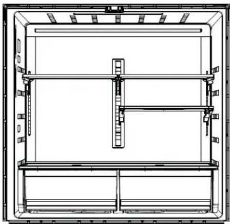
natural_image
Technical line drawing of a rectangular enclosure or storage unit with internal compartments and supports (no text or symbols)natural_image
Line drawing of hands holding a rectangular object with a horizontal bar, mounted on a wall (no text or symbols)Clayette QuickSpace
natural_image
Line drawing of a hand holding a tray with an arrow indicating upward motion (no text or symbols)natural_image
Line drawing of a refrigerator drawer with handle and drawer slot (no text or symbols)natural_image
Line drawing of a mechanical device with a sloped top and base, showing internal components and mounting brackets (no text or symbols)text_image
Technical diagram of a multi-level mechanical or electrical device with numbered components labeled 1, 2, and 3.natural_image
Line drawing of a hand using a tool to adjust or install a mechanical component (no text or symbols)Retrait du panier
Pour retirer :
natural_image
Line drawing of a hand using a tool to adjust or install a mechanical component (no text or symbols)natural_image
Technical line drawing of a mechanical device with no visible text or symbolsnatural_image
Line drawing of an open refrigerator with shelves and compartments (no text or symbols)natural_image
Line drawing of an open refrigerator with visible door, shelves, and ventilation slots (no text or symbols)natural_image
Technical line drawing of two mechanical bracket components with mounting flanges (no text or symbols)natural_image
Line drawing of a printer or printer with no visible text, numbers, or symbols
Tournevis Torx T20, T25
DIMENSIONS PGD, PGE, PJD et PJE
text_image
F E D A B C H K G X Ynatural_image
Technical line drawing of a mechanical device with two views of internal components (no text or symbols)2 INSTALLATION DE LA POIGNÉE DU RÉFRIGÉRATEUR POUR MODÈLES À PORTE INTÉRIEURE (DOOR-IN-DOOR) SEULEMENT
natural_image
Technical line drawing of a mechanical assembly or frame structure (no text or symbols)natural_image
Line drawing of a hand holding a tool near a device (no text or symbols)natural_image
Technical line drawing of a mechanical assembly with a hand holding a tool, showing internal components and alignment (no text or symbols)natural_image
Line drawing of a hand using a tool to adjust or install a mechanical component (no text or symbols)natural_image
Technical line drawing of a mechanical assembly with no visible text or symbolsATTENTION
natural_image
Technical line drawing of a refrigerator interior with an arrow indicating upward motion (no text or symbols)INSTALLATION DU RÉFRIGÉRATEUR (suite)

RETIRER LA PORTE
natural_image
Technical line drawing of a mechanical assembly with no visible text or symbolsnatural_image
Technical line drawing of a mechanical assembly with wires and brackets (no text or symbols)natural_image
Technical line drawing of a mechanical clamp or bracket assembly (no text or symbols)natural_image
Technical line drawing of a mechanical assembly or frame structure (no text or symbols)14 REINSTALLATION DE LA PORTE DU CONGÉLATEUR
ATTENTION
natural_image
Technical line drawing of a mechanical assembly or structural component (no text or symbols visible)natural_image
Mechanical diagram showing a rotating lever mechanism with no text or symbols
BRANCHEMENT DU CORDON D'ALIMENTATION DU RÉFRIGÉRATEUR
natural_image
Simple line drawing of an electrical outlet with a plug and socket (no text or symbols)
MISE À NIVEAU DU RÉFRIGÉRATEUR
natural_image
Line drawing of a refrigerator with a handle and control panel (no text or symbols)natural_image
Technical diagram showing a mechanical clamp or bracket assembly with an inset close-up of the component (no text or symbols present)natural_image
Technical line drawing of a mechanical linkage assembly (no text or symbols)INSTALLATION DU RÉFRIGÉRATEUR (suite)
natural_image
Line drawing of a bathroom sink with toilet and door (no text or symbols)INSTALLATION DU RÉFRIGÉRATEUR (suite)
natural_image
Technical line drawing of a multi-chamber refrigerator with labeled components (A, B, C), no text or symbols present.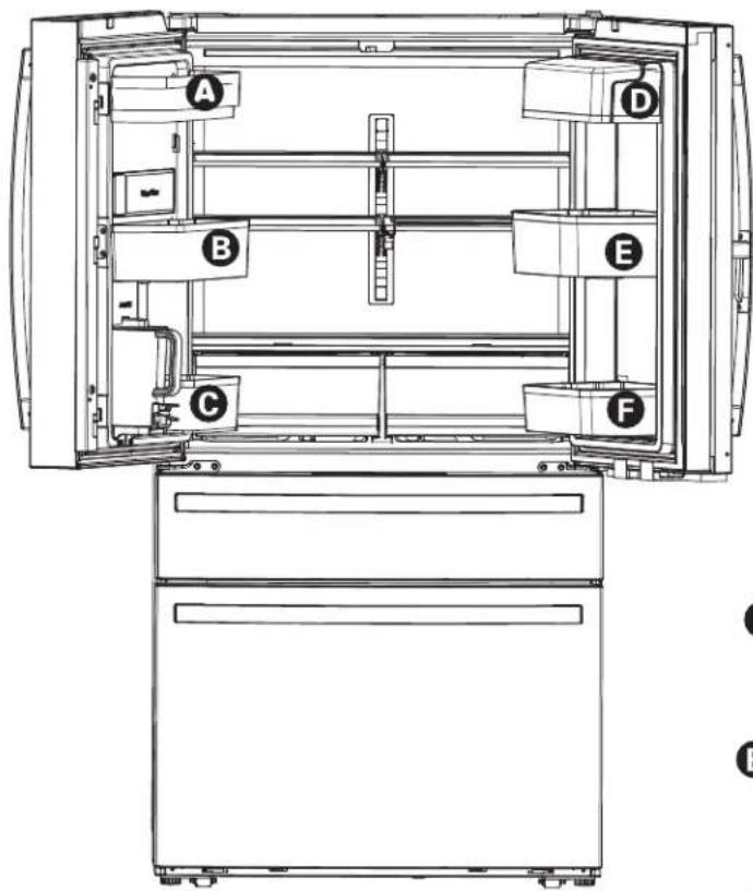
text_image
A B C D E F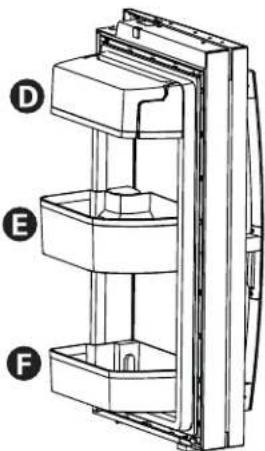
text_image
Technical diagram of a multi-tiered refrigerator with labeled parts D, E, and FSupports de position
text_image
Technical diagram of an elevator system with labeled components A, B, and C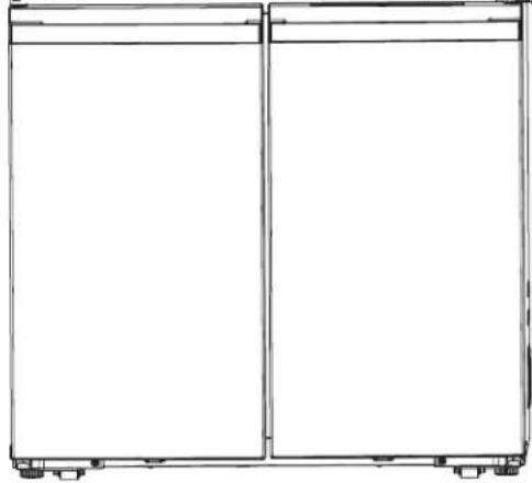
natural_image
Simple line drawing of a two-panel cabinet or enclosure with mounting feet (no text or symbols)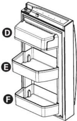
natural_image
Technical line drawing of a refrigerator with labeled compartments (D, E, F), no text or symbols present.natural_image
Pure mechanical assembly diagram showing two upward arrows indicating motion or force directions (no text or symbols)INSTALLATION DE LA CONDUITE D'EAU
AVANT DE COMMENCER
natural_image
Simple line drawing of a mechanical component with a threaded end and curved top (no text or symbols)INSTALLATION DE LA CONDUITE D'EAU (suite)
4 FASTEN THE SHUTOFF VALVE
natural_image
Simple line drawing of a flower with petals and a curved arrow, no text or symbols presentLouisville, KY 40225
Louisville, KY 40225
Au Canada : Prodsupport.mabe.ca/crm/Products/ProductRegistration.aspx
GEAppliances.com/ge/service-and-support/contact
Au Canada : Director, Customer Relations | MC Commercial Inc. | Suite 300, 5420 North Service Road | Burlington, ON L7L 6C7
Electromenagersge.ca/contactez-nous
text_image
Technical diagram of a refrigerator internal structure with numbered components for identificationtext_image
Technical diagram of a device with numbered components for identification and assembly reference.text_image
Fridge Freezer ReplaceFilter WiFi Ice Maker AutoFill Pitchernatural_image
Line drawing of a mechanical device with a handle and internal compartments (no text or symbols)Modelo PAD y PHD Zona Convertible
natural_image
Technical line drawing of a mechanical assembly with no visible text or symbolsnatural_image
Technical line drawing of a mechanical assembly with a curved arrow indicating rotation (no text or symbols)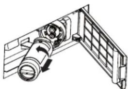
natural_image
Technical line drawing of a mechanical assembly with no visible text or symbols▲PRECAUCIÓN
natural_image
Technical line drawing of a mechanical assembly with no visible text or symbols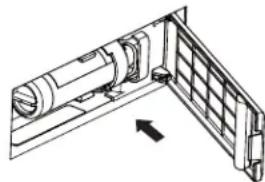
natural_image
Technical line drawing of a mechanical assembly with a bracket and internal components (no text or symbols)text_image
Diagram showing two labeled arrows pointing to a rectangular object with internal structure, possibly illustrating a mechanical or electrical component.Para reemplazar:
text_image
Technical diagram showing two labeled components (1 and 2) of a mechanical or architectural joint with alignment lines and structural details.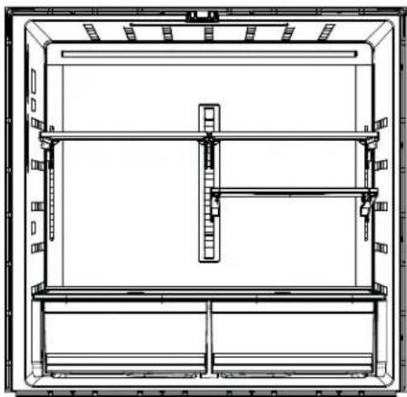
natural_image
Technical line drawing of a rectangular enclosure or storage unit with internal compartments and supports (no text or symbols)natural_image
Line drawing of hands holding a rectangular object with horizontal lines, no text or symbols presentEstante Quick Space\*
natural_image
Line drawing of a hand pressing down on a wooden tray with an arrow indicating motion (no text or symbols)natural_image
Line drawing of a refrigerator drawer with handlebars and compartments (no text or symbols)natural_image
Line drawing of a mechanical assembly with layered components and mounting brackets (no text or symbols)text_image
Technical diagram of a multi-level electronic device with numbered components for identificationnatural_image
Line drawing of a hand using a tool to adjust or install a mechanical component (no text or symbols)Retiro de la Cesto
Para retirar:
natural_image
Line drawing of a hand using a tool to adjust or install a mechanical component (no text or symbols)natural_image
Technical line drawing of a mechanical assembly with no visible text or symbolsnatural_image
Line drawing of an open refrigerator with shelves and a drawer (no text or symbols)natural_image
Line drawing of a refrigerator interior showing front and rear doors with shelves and ventilation grilles (no text or symbols)natural_image
Technical line drawing of two mechanical components with mounting brackets and alignment guides (no text or symbols)Liberar palanca
Zona Congeladora o Convertible PHD Retirada de la cesta
Para retirar:
natural_image
Line drawing of a printer with paper spool and paper holder (no text or symbols)text_image
F E D A B C H K G X Y I Jtext_image
G J F H I■ Do not install the refrigerator where the temperature will go below 60^ F ( 16^ C) because it will not run often enough to maintain proper temperatures.
■ Do not install the refrigerator where the temperature will go above 100^ F ( 37^ C) because it will not perform properly.
■ Do not install the refrigerator in a location exposed to water (rain, etc.) or direct sunlight.
■ Install it on a floor strong enough to support it fully loaded.
ESPACIO NECESARIO
natural_image
Technical line drawing of a refrigerator with internal door and handle, showing two views of the door handle (no text or symbols present)To reassemble doors, reverse removal steps.
natural_image
Technical line drawing of a mechanical assembly with no visible text or symbolsnatural_image
Line drawing showing two hands operating a tool with a handle and cable (no text or symbols)natural_image
Technical line drawing of a mechanical assembly with no visible text or symbolsnatural_image
Line drawing of a hand using a tool to adjust or install a mechanical component (no text or symbols)natural_image
Technical line drawing of a mechanical assembly with no visible text or symbolsPRECAUCIÓN
natural_image
Technical line drawing of a mechanical assembly with an arrow indicating direction (no text or symbols present)CÓMO INSTALAR EL REFRIGERADOR (Cont.)

natural_image
Technical line drawing of a mechanical assembly with no visible text or symbolsnatural_image
Technical line drawing of a mechanical assembly with no visible text or symbolsnatural_image
Technical line drawing of a mechanical assembly with bolts and brackets (no text or symbols)natural_image
Technical line drawing of a mechanical assembly or frame structure (no text or symbols)14 REEMPLAZO DE LA PUERTA DEL FREEZER
APRECAUCIÓN
natural_image
Technical line drawing of a mechanical assembly or structural component (no visible text or symbols)natural_image
Mechanical assembly diagram showing a lever mechanism with rotating arrows (no text or symbols)19 ENCHUFE EN EL REFRIGERADOR
natural_image
Simple line drawing of an electrical outlet with a plug inserted into a socket (no text or symbols)text_image
Raise Flat-Head Screwdrivernatural_image
Mechanical assembly diagram showing a lever mechanism and a close-up of the lever (no text or symbols present)natural_image
Mechanical assembly diagram showing a lever mechanism with no text or symbolsCÓMO INSTALAR EL REFRIGERADOR (Cont.)
natural_image
Technical line drawing of an internal refrigerator with labeled components (A, B, C), no text or symbols present.natural_image
Line drawing of a cabinet or storage unit with mounting brackets and doorways (no text or symbols)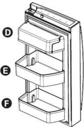
natural_image
Technical line drawing of a refrigerator with labeled compartments (D, E, F), no text or symbols present.CÓMO INSTALAR EL REFRIGERADOR (Cont.)
Modelos Profile de Cuatro Puertas Door-in-Door
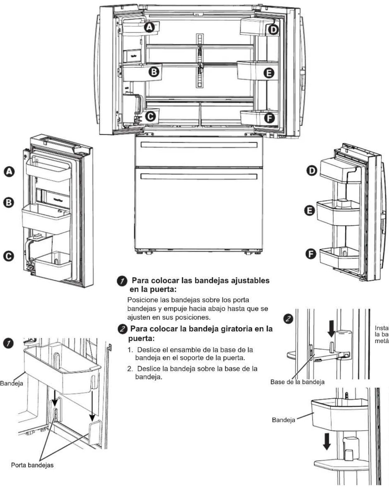
natural_image
Technical line drawing of a refrigerator interior with labeled components (A, B, C), showing no text or symbols beyond labels.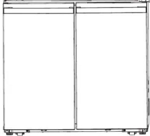
natural_image
Line drawing of a two-panel cabinet or enclosure with mounting feet (no text or symbols)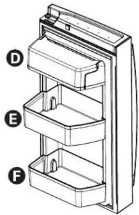
natural_image
Diagram of a refrigerator with labeled parts (D, E, F), showing internal compartments and casing layout (no text or symbols beyond labels)natural_image
Pure mechanical assembly diagram showing two upward arrows indicating motion or force direction (no text or symbols)CÓMO INSTALAR LA TUBERÍA DE AGUA
ANTES DE COMENZAR
natural_image
Simple line drawing of a mechanical joint or bracket (no text or symbols)natural_image
Simple line drawing of a flower with a curved arrow, no text or symbols presentWarrantor: GE Appliances, a Haier company
Louisville, KY 40225
Warrantor Canada: MC Commercial, Burlington, Ontario, L7R 5B6
Louisville, KY 40225