GSS25WGMCC - Fridge GE - Free user manual and instructions
Find the device manual for free GSS25WGMCC GE in PDF.

User questions about GSS25WGMCC GE
0 question about this device. Answer the ones you know or ask your own.
Ask a new question about this device
Download the instructions for your Fridge in PDF format for free! Find your manual GSS25WGMCC - GE and take your electronic device back in hand. On this page are published all the documents necessary for the use of your device. GSS25WGMCC by GE.
USER MANUAL GSS25WGMCC GE
Safety Instructions .....2, 3
For Australia and New Zealand . . .34
Operating Instructions
Additional Features .....11
Automatic Icemaker .....15
Care and Cleaning .....17, 18
Crispers and Pans .....14
CustomCool™ 4,7,8
Freezer Compartment .....13
Ice and Water Dispenser .....16, 17
Refrigerator Doors .....10
Replacing the Light Bulbs .....19
Shelves and Bins .....10–12
Temperature Controls .....4, 5, 6
Turbo Cool ^™ .....6
Water Filter 9
Installation Instructions
For Australia and
New Zealand .....35-37
Preparing to Install
the Refrigerator .....25-27
Removing and Replacing Doors . . .24
Trim Kits and Panels .....20–23
Water Line Installation .....28, 29
Troubleshooting Tips .....31-33
Normal Operating Sounds .....30
Write the model and serial numbers here:
Model #
Serial #
Find these numbers on a label inside the refrigerator compartment at the top on the right.
Owner's Manual and Installation
Models 21, 23, 25, 27 and 29
Côte à Côte
Réfrigérateurs
Use this appliance only for its intended purpose as described in this Owner's Manual.

SAFETY PRECAUTIONS
When using electrical appliances, basic safety precautions should be followed, including the following:
This refrigerator must be properly installed and located in accordance with the Installation Instructions before it is used. Also see the How to Connect Electricity section.
Do not attempt to stand on top of the refrigerator. Doing so may result in bodily injury or damage to the refrigerator.
Do not allow children to play with the refrigerator or tamper with the controls.
Do not allow children to climb, stand or hang on the shelves in the refrigerator. They could damage the refrigerator and seriously injure themselves.
Do not touch the cold surfaces in the freezer compartment when hands are damp or wet. Skin may stick to these extremely cold surfaces.
Do not store or use gasoline or other flammable vapors and liquids in the vicinity of this or any other appliance.
In refrigerators with automatic icemakers, avoid contact with the moving parts of the ejector mechanism, or with the heating element located on the bottom of the icemaker. Do not place fingers or hands on the automatic icemaking mechanism while the refrigerator is plugged in.
Installation of the icemaker must be done by a qualified service technician.
- Keep fingers out of the “pinch point” areas; clearances between the doors and between the doors and cabinet are necessarily small. Be careful closing doors when children are in the area.
■ Unplug the refrigerator before cleaning and making repairs.
NOTE: We strongly recommend that any servicing be performed by a qualified individual.
Before replacing a burned-out light bulb, the refrigerator should be unplugged in order to avoid contact with a live wire filament. (A burned-out light bulb may break when being replaced.)
NOTE: Setting either or both controls to 0 (off) does not remove power to the light circuit.
Do not refreeze frozen foods which have thawed completely.
■ Always clean the CustomCool™ Tray after thawing food.
▲ DANGER! RISK OF CHILD ENTRAPMENT
PROPER DISPOSAL OF THE REFRIGERATOR
Child entrapment and suffocation are not problems of the past. Junked or abandoned refrigerators are still dangerous...even if they will sit for “just a few days.” If you are getting rid of your old refrigerator, please follow the instructions below to help prevent accidents.
Before You Throw Away Your Old Refrigerator or Freezer:
Take off the doors and discard separately.
Leave the shelves in place so that children may not easily climb inside.
If the refrigerator has a lock, make it unusable.
Refrigerants
All refrigeration products contain refrigerants, which under federal law must be removed prior to product disposal. If you are getting rid of an old refrigeration product, check with the company handling the disposal about what to do.
▲ WARNING!
HOW TO CONNECT ELECTRICITY
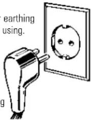
The power cord of this appliance is equipped with an earthing plug which mates with a standard earthed wall outlet to minimize the possibility of electric shock hazard from this appliance.
Have the wall outlet and circuit checked by a qualified electrician to make sure the outlet is properly earthed.
Where an unearthed wall outlet is encountered, it is your personal responsibility and obligation to have it replaced with a properly earthed wall outlet.
The refrigerator should always be plugged into its own individual electrical outlet. This provides the best performance and also prevents overloading house Insure proper earthing exists before using.
text_image
earthing using.Earthing plug
wiring circuits which could cause a fire hazard from overheated wires. Please refer to the rating plate on the refrigerator for the correct voltage, wattage and frequency. If the product plug does not fit your outlet, the product should be fitted with a new plug. IMPORTANT: The refitting of electric plugs and cables should be done by a qualified technician or service agent. In some countries the refitting of electric plugs and cables is only permitted when the work is completed by a qualified technician.
If the power supply cord becomes damaged, it must be replaced by a qualified service agent in order to avoid a safety hazard.
Never unplug your refrigerator by pulling on the power cord. Always grip plug firmly and pull straight out from the outlet.
Repair or replace immediately all power cords that have become frayed or otherwise damaged. Do not use a cord that shows cracks or abrasion damage along its length or at either end.
When moving the refrigerator away from the wall, be careful not to roll over or damage the power cord.
Mains lead replacement
If the mains lead on your refrigerator needs replacing at any time, it must be replaced by a special lead which is obtainable from your local dealer. A charge will be made for the replacement of the mains lead if you have damaged the lead.
The refrigerator must be positioned so that the plug is accessible.

READ AND FOLLOW THIS SAFETY INFORMATION CAREFULLY.
SAVE THESE INSTRUCTIONS
text_image
-18 SET 3 SET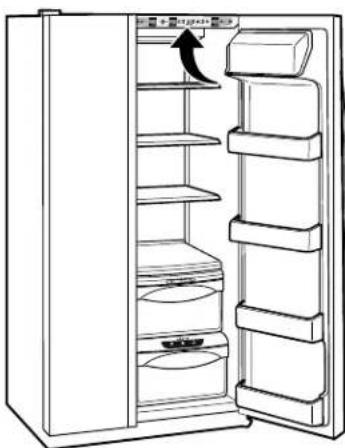
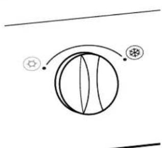
natural_image
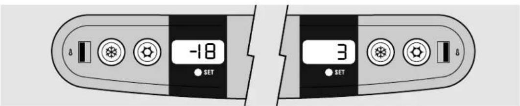
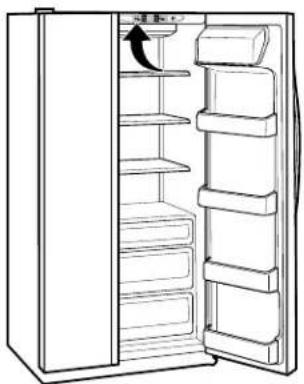
Line drawing of an open refrigerator with shelves and a door, showing no text or symbolsThe temperature controls are preset in the factory at 3^ C for the refrigerator compartment and -18^ C for the freezer compartment. Allow 24 hours for the temperature to stabilize to the preset recommended settings.
The temperature controls can display both the SET temperature as well as the actual temperature in the refrigerator and freezer. The actual temperature may vary slightly from the SET temperature based on usage and operating environment.
Setting either or both controls to 0 (off) stops cooling in both the freezer and refrigerator compartments, but does not shut off electrical power to the refrigerator.
NOTE: The refrigerator is shipped with protective film covering the temperature controls. If this film was not removed during installation, remove it now.
To change the temperature, press and release the + or - pad. The SET light will come on and the display will show the set temperature. To change the temperature, tap either the + or - pad until the desired temperature is displayed. Refrigerator temperatures can be adjusted between 1°C and 7°C and the freezer temperatures can be adjusted between -21°C and -14°C.
Once the desired temperature has been set, the temperature display will return to the actual refrigerator and freezer temperatures after 5 seconds. Several adjustments may be required. Each time you adjust controls, allow 24 hours for the refrigerator to reach the temperature you have set.
To turn the cooling system off, tap the + pad for either the refrigerator or the freezer until the display shows 0 (off). To turn the unit back on, press the - pad for either the refrigerator or freezer. The SET light will illuminate on the side you selected. Then press the - pad again (on the side where the SET light is illuminated) and it will go to the preset points of -18^ for the freezer and 3^ for the refrigerator. Setting either or both controls to 0 (off) stops cooling in both the freezer and refrigerator compartments, but does not shut off electrical power to the refrigerator.
Ambient Room Temperature Limits
This refrigerator is designed to operate in ambient temperatures specified by its Temperature Class, which is marked on the rating plate.
| Temperature Symbol Ambient Temperature | ||
| Class Maximum | Minimum | |
| Extended-Temperate SN 32°C 10°C | ||
| Temperate N 32°C 16°C | ||
| Subtropical ST | 38°C 18°C | |
| Tropical | T | 43°C 18°C |
NOTE: Internal temperature may be affected by such factors as the location of the refrigerator, ambient temperature and frequency of door openings. Adjust temperature controls as required to compensate for these factors.
About the temperature controls.
text_image
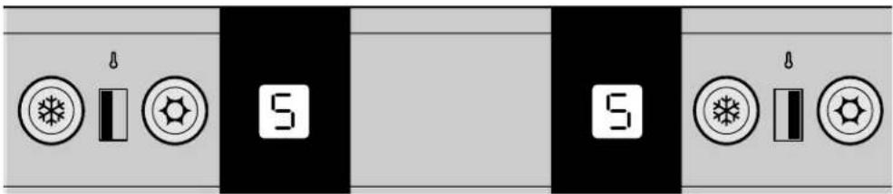
5 5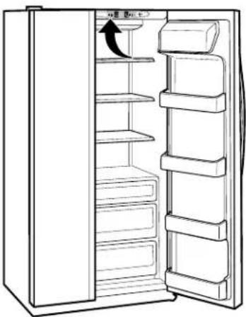
natural_image
Line drawing of a refrigerator with shelves and doors open, showing an arrow indicating the door handle (no text or symbols present)The temperature controls are preset in the factory at 5 for both the refrigerator and freezer compartments. Allow 24 hours for the temperature to stabilize to the preset settings.
Several adjustments may be required. Each time you adjust controls, allow 24 hours after each adjustment for the refrigerator to reach the setting you have selected.
Setting either or both controls to 0 stops cooling in both the freezer and refrigerator compartments, but does not shut off electrical power to the refrigerator.
Control settings will vary based on personal preferences, usage and operating conditions and may require more than one adjustment.
NOTE: The refrigerator is shipped with protective film covering the temperature controls. If this film was not removed during installation, remove it now.
Ambient Room Temperature Limits
This refrigerator is designed to operate in ambient temperatures specified by its Temperature Class, which is marked on the rating plate.
| Temperature Symbol Ambient Temperature Class Maximum Minimum | ||
| Extended-Temperate SN 32°C 10°C | ||
| Temperate N 32°C 16°C | ||
| Subtropical ST 38°C 18°C | ||
| Tropical T 43°C 18°C | ||
NOTE: Internal temperature may be affected by such factors as the location of the refrigerator, ambient temperature and frequency of door openings. Adjust temperature controls as required to compensate for these factors.
About the temperature controls.
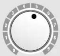
FREEZER

FRESH FOOD
9 IS COLDEST 0 IS OFF
natural_image
Line drawing of an open refrigerator with shelves and a door, showing no text or symbolsThe temperature controls are preset in the factory at 5 for both the refrigerator and freezer compartments. Allow 24 hours for the temperature to stabilize to the preset settings.
Several adjustments may be required. Each time you adjust controls, allow 24 hours after each adjustment for the refrigerator to reach the setting you have selected.
Setting either or both controls to 0 stops cooling in both the freezer and refrigerator compartments, but does not shut off electrical power to the refrigerator.
Control settings will vary based on personal preferences, usage and operating conditions and may require more than one adjustment.
NOTE: The refrigerator is shipped with protective film covering the temperature controls. If this film was not removed during installation, remove it now.
Ambient Room Temperature Limits
This refrigerator is designed to operate in ambient temperatures specified by its Temperature Class, which is marked on the rating plate.
| Temperature Symbol Ambient Temperature | ||
| Class Maximum | Minimum | |
| Extended-Temperate SN 32°C 10°C | ||
| Temperate N 32°C 16°C | ||
| Subtropical ST 38°C 18°C | ||
| Tropical T 43°C 18°C | ||
NOTE: Internal temperature may be affected by such factors as the location of the refrigerator, ambient temperature and frequency of door openings. Adjust temperature controls as required to compensate for these factors.
About TurboCool™.

How it Works
TurboCool rapidly cools the refrigerator compartment in order to more quickly cool foods. Use TurboCool when adding a large amount of food to the refrigerator compartment, putting away foods after they have been sitting out at room temperature or when putting away warm leftovers. It can also be used if the refrigerator has been without power for an extended period.
Once activated, the compressor will turn on immediately and the fans will cycle on and off at high speed as needed for eight hours. The compressor will continue to run until the refrigerator compartment cools to approximately 1°C, then it will cycle on and off to maintain this setting. After 8 hours, or if TurboCool is
pressed again, the refrigerator compartment will return to the original setting.
How to Use
Press TurboCool. The TurboCool indicator light will come on.
After TurboCool is complete, the TurboCool indicator light will go out.
NOTES: The refrigerator temperature cannot be changed during TurboCool.
The freezer temperature is not affected during TurboCool.
When opening the refrigerator door during TurboCool, the fans will continue to run if they have cycled on.
text_image
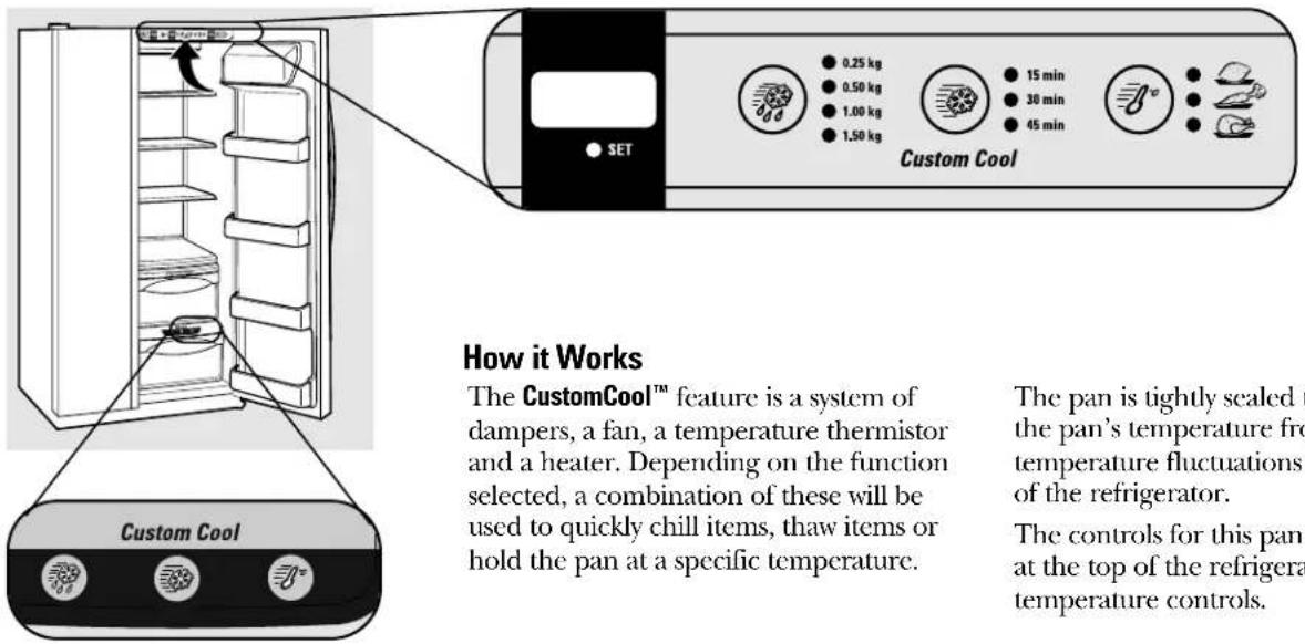
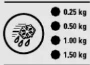
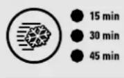
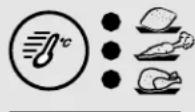
SET 0.25 kg 0.50 kg 1.00 kg 1.50 kg 15 min 30 min 45 min Custom Cool How it Works The CustomCool™ feature is a system of dampers, a fan, a temperature thermistor and a heater. Depending on the function selected, a combination of these will be used to quickly chill items, thaw items or hold the pan at a specific temperature. The pan is tightly sealed to the pan's temperature from temperature fluctuations of the refrigerator. The controls for this pan at the top of the refrigeration temperature controls.How it Works
The CustomCool™ feature is a system of dampers, a fan, a temperature thermistor and a heater. Depending on the function selected, a combination of these will be used to quickly chill items, thaw items or hold the pan at a specific temperature.
The pan is tightly sealed to prevent the pan's temperature from causing temperature fluctuations in the rest of the refrigerator.
The controls for this pan are located at the top of the refrigerator with the temperature controls.
text_image
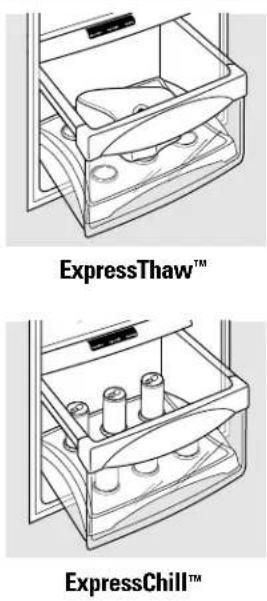
ExpressThaw™ ExpressChill™How to Use
Empty the pan. Place the Chill/Thaw tray in the pan with the metal plate facing down to chill and store items, or with the metal plate facing up to thaw items. Place the items on the tray and close the pan completely.
2 Select the ExpressThaw™ , ExpressChill™ or SelectTemp™ pad. The display and SET light will come on. Tap the pad until the light appears next to the desired setting. Use the chart to determine the best setting to use.
To stop a feature before it is finished, tap that feature's pad until no options are selected and the display is off.
During ExpressThaw ^™ and ExpressChill, ^™ the display on the controls will count down the time in the cycle.
After the ExpressThaw™ cycle is complete, the pan will reset to the MEAT setting (-1^) to help preserve thawed items until they are used.
The displayed actual temperature of the CustomCool pan may vary slightly from the SET temperature based on usage and operating environment.
NOTE: For food safety reasons, it is recommended that foods be wrapped in plastic wrap when using ExpressThaw. ^™ This will help contain meat juices and improve thawing performance.
CustomCool™ Chart
NOTE: Results may vary depending on packaging, starting temperature and other food traits.
ExpressThaw
ExpressChill
SelectTemp
0.25 kg (4 hours)
■Hamburgers (0.25 kg)
■ Individually Wrapped
Filet Mignon (0.25 kg)
0.50 kg (8 hours)
Chicken Breasts (0.5 kg)
■Minced Beef (0.5 kg)
■ Steak (0.5 kg)
1.0 kg (10 hours)
Chicken Breasts (1.0 kg)
■Minced Beef (1.0 kg)
■Steak (1.0 kg)
1.50 kg (12 hours)
Chicken Breasts (1.50 kg)
■Minced Beef (1.50 kg)
■ Steak (1.50 kg)
15 Minutes
■1 Beverage Can (355 ml)
■2 Small Juice Boxes (175–240 ml each)
30 Minutes
■2 to 6 Beverage Cans (355 ml each)
■2 Plastic 590 ml Bottles of Beverage
■4 to 6 Small Juice Boxes (175–240 ml each)
■3 Foil Juice Packets
■ Wine (750 ml bottle)
45 Minutes
■2 Liter of Beverage
■ 1.9 Liters of Juice
Gelatin-1 package
Citrus Setting (6°C)
Oranges, Lemons, Limes, Pineapple, Cantaloupe
Beans, Cucumbers, Tomatoes, Peppers, Aubergine, Squash
Produce Setting (1°C)
Strawberries, Raspberries, Kiwifruit, Pears, Cherries, Blackberries, Grapes, Plums, Nectarines, Apples
Asparagus, Broccoli, Corn,
Mushrooms, Spinach, Cauliflower,
Kale, Green Onion, Beetroot, Onions
Meat Setting ( -1^ )
Raw Meat, Fish and Poultry
natural_image
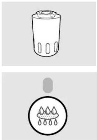
Two technical illustrations: top shows a cylindrical container with internal features, bottom shows a droplet with liquid drops (no text or symbols)Water Filter Cartridge (on some models)
The water filter cartridge is located in the back upper right corner of the refrigerator compartment.
When to Replace the Filter
There is a replacement indicator light for the water filter cartridge on the dispenser. This light will turn orange to tell you that you need to replace the filter soon.
The filter cartridge should be replaced when the replacement indicator light turns red or if the flow of water to the dispenser or icemaker decreases.
Installing the Filter Cartridge
If you are replacing the cartridge, first remove the old one by slowly turning it to the left. Do not pull down on the cartridge. A small amount of water may drip down.
2 Fill the replacement cartridge with water from the tap to allow for better flow from the dispenser immediately after installation.
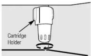
3 Lining up the arrow on the cartridge and the cartridge holder, place the top of the new cartridge up inside the holder. Do not push it up into the holder.
Slowly turn it to the right until the filter cartridge stops. DO NOT OVERTIGHTEN. As you turn the cartridge, it will automatically raise itself into position. Cartridge will rotate about 1/4 turn.
4 Run water from the dispenser for 3 minutes (about six liters) to clear the system and prevent sputtering.
5 Press and hold the RESET WATER FILTER pad on the dispenser for 3 seconds.
NOTE: A newly-installed water filter cartridge may cause water to spurt from the dispenser.
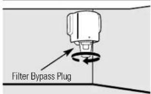
Filter Bypass Plug
text_image
Filter Bypass PlugYou must use the filter bypass plug when a replacement filter cartridge is not available. The dispenser and the icemaker will not operate without the filter or filter bypass plug.
Replacement Filters:
To order additional filter cartridges, contact your local distributor.
text_image
Cartridge HolderPlace the top of the cartridge up inside the cartridge holder and slowly turn it to the right.
About the refrigerator doors.
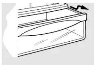
natural_image
Diagram of a refrigerator interior showing internal compartments and directional arrows indicating movement (no text or labels)When the door is only partially open it will automatically close.
Beyond this stop the door will stay open.
Refrigerator Doors
The refrigerator doors may feel different than the ones you are used to. The special door opening/closing feature makes sure the doors close all the way and are securely sealed.
When opening and closing the door you will notice a stop position. If the door is opened past this stop point, the door will remain open to allow you to load and unload food more easily. When the door is only partially open, it will automatically close.
The resistance you feel at the stop position will be reduced as the door is loaded with food.
About the shelves and bins.
Not all features are on all models.
text_image
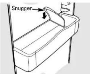
SnuggerRefrigerator bin
natural_image
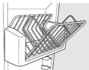
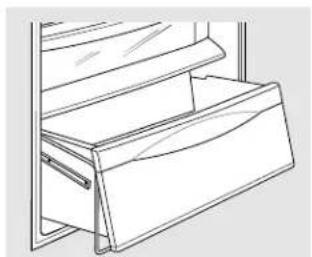
Line drawing of a mechanical device with internal mesh structure (no text or symbols)Freezer tilt-out bin
Refrigerator Door Bins and Freezer Door Tilt-Out Bins
Large Bins
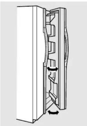
The larger refrigerator door bins and freezer tilt-out door bins are adjustable.
To remove: Lift the front of the bin straight up, then lift up and out.
To replace or relocate: Engage the back side of the bin in the molded supports of the door. Then push down on the front of the bin. Bin will lock in place.
Small Bins
To remove: Lift the front of the bin straight up then out.
To replace: Position the bin above the rectangular molded supports on the door. Then slide the bin down onto the support to lock it in place.
The snugger helps prevent tipping, spilling or sliding of small items stored on the door shelf. Place a finger on either side of the snugger near the rear and move it back and forth to fit your needs.
text_image
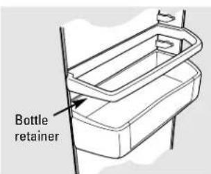
Bottle retainerBottle Retainer
The bottle retainers are adjustable and keep tall items from tipping over.
To remove: Lift the front of the retainer straight up, then lift it up.
To replace or relocate: Engage the back of the bottle retainer in the molded supports on the door. Then push down on the front of the bottle retainer.
natural_image
Pure technical line drawing of a mechanical component or assembly (no text or symbols)Press tab and pull shelf forward to remove
Slide-Out Spillproof Shelf
The slide-out spillproof shelf allows you to reach items stored behind others. The special edges are designed to help prevent spills from dripping to lower shelves.
position, line up with the supports and slide into place.
Make sure you push the shelves all the way back in before you close the door.
To remove:
Slide the shelf out until it reaches the stop, then press down on the tab and slide the shelf straight out.
natural_image
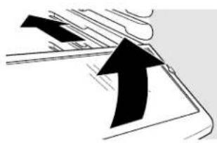
Pure diagram of a mechanical or architectural component with no visible text, numbers, or symbolsTo replace or relocate:
Line the shelf up with the supports and slide it into place. The shelf can be repositioned when the door is at 90^ or more. To reposition the shelf, slide the shelf past the stops and angle downward. Slide shelf down to the desired
natural_image
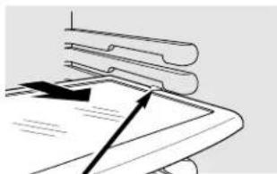
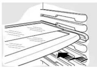
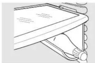
Illustration of stacked documents with a black arrow pointing to one document (no text or symbols present)QuickSpace™ Shelf
This shelf splits in half and slides under itself for storage of tall items on the shelf below.
On some models, this shelf can not be used in the lowest position.
This shelf can be removed and replaced or relocated just like Slide-Out Spillproof Shelves.
natural_image
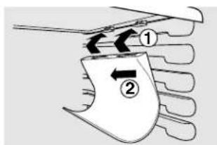
Line drawing of a hand holding a device with a scroll wheel (no text or symbols)Removable Beverage Rack
The beverage rack is designed to hold a bottle on its side. It can be attached to any slide-out shelf.
To install:
7 Line up the large part of the slots on the top of the rack with the tabs under the shelf.
② Then slide the rack back to lock it in place.
text_image
Diagram showing two labeled parts (① and ②) with directional arrows indicating movement or flow between them.
natural_image
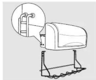
Line drawing of a mechanical device with rollers and a lid (no text or symbols)Door Wine/Beverage Rack (on some models)
This rack holds up to 5 cans, one bottle of wine or one 2-liter bottle of soda.
To replace:
⑦ Reattach the rack to the sides of the bin.
2 Engage the back side of the bin in the molded supports on the door. Then push down on the front of the bin. The bin will lock into place.
natural_image
Line drawing of a mailbox with ladder and support structure (no text or symbols)About the shelves and bins.
Not all features are on all models.
text_image
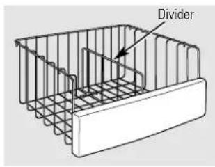
DividerDeep Freezer Baskets
To remove, push the basket all the way to the back of the freezer. Lift up until the back pins are disengaged. Lift the entire basket up and pull out.
The divider can be used to organize food packages. For large packages, simply fold down the divider.
Make sure you push the baskets all the way back in before you close the door.
WARNING: Poor performance may occur if freezer baskets are not used. Storage of items in the freezer without using baskets may result in poor temperature performance due to restrictions of air flow within the freezer compartment.
natural_image
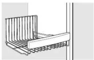
Technical line drawing of a structural support bracket with vertical ribs and horizontal beams (no text or symbols)Freezer Baskets
To remove, slide out to the stop position, lift the front past the stop position and slide out.
Make sure you push the baskets all the way back in before you close the door.
WARNING: Poor performance may occur if freezer baskets are not used. Storage of items in the freezer without using baskets may result in poor temperature performance due to restrictions of air flow within the freezer compartment.
natural_image
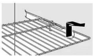
Technical line drawing of a metal grate with a black clip and support bracket (no text or symbols)Slide-Out Freezer Shelves
To remove, slide out to the stop position, lift the front past the stop position and slide out.
Make sure you push the shelves all the way back in before you close the door.
text_image
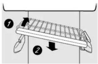
Diagram showing two labeled parts of a mechanical device with arrows indicating direction or movementFixed Freezer Shelves
There are two types of fixed freezer shelves.
To remove this type of shelf:
1 Lift the shelf up at the left side.
2 Bring the shelf out.
To remove this type of shelf:
7 Lift up the left side of the shelf and slide it left into the center of the shelf supports.
2 Rotate the right side of the shelf up and out of the shelf supports.
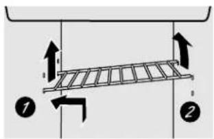
text_image
Diagram showing a ladder structure with directional arrows and numbered components 1 and 2Loading the Freezer Compartment
Load so that at least 15 mm of space remains clear between stacks of packages and 15 mm to 25 mm of space between the top of any stack and any shelf or basket above it. Packages may hang over the front of shelves but must remain 15 mm from doors.
Food to be frozen must not be placed in direct contact with food in storage. If food is to be frozen every day, it may be necessary to reduce the quantity to be frozen.
If a quantity of food needs to be frozen, set the freezer control to its coldest setting. After the food is frozen, reset the freezer control to its initial position.
Food is most quickly frozen on the middle three shelves of the freezer compartment and most slowly in the freezer door shelves.
- Do not store commercially quick-frozen food longer than the time recommended by the food manufacturers.
If the power to the appliance is shut off for an extended time or if the refrigerating system fails, do not open the doors unless absolutely necessary. When it is necessary, close them as quickly as possible so the frozen food will stay frozen as long as possible.
The freezer door storage shelves marked with a two-star label are only appropriate for the storage of previously frozen food.
Effervescent drinks should not be stored in the freezer compartment.
Freezer Performance
This Refrigerator/Freezer has an overall "Four Star" rating.
Freezer performance is classified by star ratings defined by ISO 8561 STANDARD AND SUMMARY BELOW:
| CODE | FREEZING-LOAD TEMP.(FOOD TEMPERATURE) | ||
| [22H2] | Below -6°C. | ||
 | Below -12°C. | ||
 | or | [T022] | Below -18°C. |
However, these limited areas have a two star rating as permitted by the standard:
| Models Location of Freezer Shelves | |
| 21, 23 Bottom freezer basket and bottom 2 door shelves, top freezer door shelf. | |
| 25 Shelf | above the ice bucket, top freezer door shelf and bottom 2 door shelves. |
| 27 Shelf | above the ice bucket, top freezer door shelf and bottom 2 door shelves. |
| 29 Bottom 2 freezer door shelves. | |
| 23 NON DISPENSER | Top freezer door shelf. |
| 23 CUBED & CRUSHED DISPENSER | Bottom 3 door shelves. |
About the crispers and pans.
Not all features are on all models.
natural_image
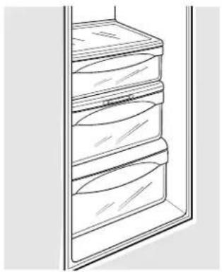
Line drawing of a refrigerator with three shelves and a door (no text or symbols)Fruit and Vegetable Crispers
Excess water that may accumulate in the bottom of the drawers should be wiped dry.
On some models the bottom drawer has a cover that slides back as the drawer is opened. This allows full access to the drawer. As the drawer is closed, the cover will slide forward into its original position.
Adjustable Humidity Crispers
Slide the control all the way to the (high) setting to provide high humidity recommended for most vegetables.
Slide the control all the way to the (low) setting to provide lower humidity levels recommended for most fruits.
natural_image
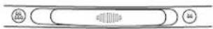
Simple line drawing of a circular object with internal vertical lines and two small circles on the sides (no text or symbols)Convertible Meat Pan
The convertible meat pan has its own cold air duct to allow a stream of cold air from the freezer compartment to flow to the pan.
The variable temperature control regulates the air flow from the Climate Keeper. ^™
Set the control to the ⓖoldest) setting to store fresh meats.
Set the control to (cold) to convert the pan to normal refrigerator temperature and provide extra vegetable storage space. The cold air duct is turned off. Variable settings between these extremes can be selected.
About crisper removal.
Not all features are on all models.
natural_image
Pure technical line drawing of a mechanical component or housing (no text or symbols)Crisper Removal
The top crispers can easily be removed by pulling the drawer straight out and lifting the drawer up and over the stop location.
If the door prevents you from taking out the drawers, first try to remove the door bins. If this does not offer enough clearance, the refrigerator will need to be rolled forward until the door opens enough to slide the drawers out. In some cases, when you roll the refrigerator out, you will need to move the refrigerator to the left or right as you roll it out.
To replace the bottom crisper:
Place the back of the drawer in the wire holder, making sure the wire holder fits into the grooves on the back of the pan.
2 Lower the front of the drawer into the wire holder.
3 Pull the bottom of the wire holder forward until the wire pops into the groove located on the bottom of the drawer.
natural_image
Line drawing of a mechanical assembly or lifting mechanism (no text or symbols)To remove the bottom crisper:
7 Pull the drawer out to the stop position.
2 Lift the front of the drawer up and out of the wire holder.
3 Lift the back of the drawer up and out.
natural_image
Simple line drawing of a container with arrows indicating flow or movement (no text or symbols)Pop wire into groove.
A newly-installed refrigerator may take 12 to 24 hours to begin making ice.
text_image
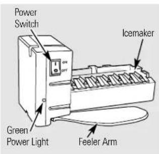
Power Switch Green Power Light Feeler Arm IcemakerAutomatic Icemaker
The icemaker will produce seven cubes per cycle—approximately 100–130 cubes in a 24-hour period, depending on freezer compartment temperature, room temperature, number of door openings and other use conditions.
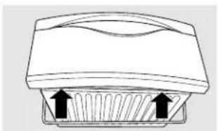
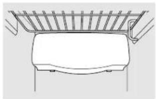
To access the icemaker: Pull the shelf above the ice drawer straight out. Always be sure to replace the shelf.
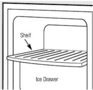
text_image
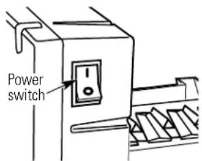
Shelf Ice DrawerIf the refrigerator is operated before the water connection is made to the icemaker, set the power switch in the 0 position.
When the refrigerator has been connected to the water supply, set the power switch to the I position.
You will hear a buzzing sound each time the icemaker fills with water.
The icemaker will fill with water when it cools to -10^ C. A newly-installed refrigerator may take 12 to 24 hours to begin making ice cubes.
Throw away the first few batches of ice to allow the water line to clear.
Be sure nothing interferes with the sweep of the feeler arm.
When the bin fills to the level of the feeler arm, the icemaker will stop producing ice. It is normal for several cubes to be joined together.
If ice is not used frequently, old ice cubes will become cloudy, taste stale and shrink.
If ice cubes get stuck in the icemaker, the green power light will blink. To correct this, set the power switch to 0 and remove the cubes. Set the power switch to 1 to restart the icemaker. After the icemaker has been turned on again, there will be a delay of about 45 minutes before the icemaker resumes operation.
NOTE: In homes with lower-than-average water pressure, you may hear the icemaker cycle multiple times when making one batch of ice.
WARNING: Connect to potable water supply only. Installation of the icemaker must be done by a qualified service technician.
Pull the upper freezer shelf straight out to access the icemaker. Always be sure to replace the shelf. The shelf can be used for storage.
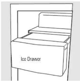
text_image
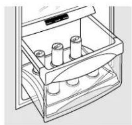
Ice DrawerIce Storage Drawer
To access ice, pull the drawer forward.
To remove the drawer, pull it straight out and lift it past the stop location.
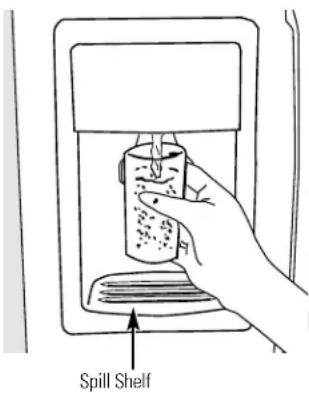
text_image
Spill ShelfTo Use the Dispenser
Select CUBED ICE 🎨, CRUSHED ICE 🎨 or WATER 🎨.
Press the glass gently against the top of the dispenser pad/cradle.
The spill shelf is not self-draining. To reduce water spotting, the shelf and its grille should be cleaned regularly.
If no water is dispensed when the refrigerator is first installed, there may be air in the water line system. Press the dispenser pad/cradle for at least two minutes to remove trapped air from the water line and to fill the water system. To flush out impurities in the water line, throw away the first six glassfuls of water.
CAUTION: Never put fingers or any other objects into the ice crusher discharge opening.
Locking the Dispenser (on some models)
Press the LOCK CONTROL pad for 3 seconds to lock the dispenser and control panel. To unlock, press and hold the pad again for 3 seconds.
Dispenser Light (on some models)
This pad turns the night light in the dispenser on and off. The light also comes on when the dispenser pad/cradle is pressed. If this light burns out, it should be replaced with a 6 watt 12V maximum bulb.
Door Alarm (on some models)
To set the alarm, press this pad until the indicator light comes on. This alarm will sound if either door is open for more than 3 minutes. The light goes out and the beeping stops when you close the door.
Important Facts About Your Dispenser
Do not add ice from trays or bags to the storage drawer. It may not crush or dispense well.
Avoid overfilling glass with ice and use of narrow glasses. Backed-up ice can jam the chute or cause the door in the chute to freeze shut. If ice is blocking the chute, poke it through with a wooden spoon.
■ Beverages and foods should not be quick-chilled in the ice storage drawer. Cans, bottles or food packages in the storage drawer may cause the icemaker or auger to jam.
To keep dispensed ice from missing the glass, put the glass close to, but not touching, the dispenser opening.
Some crushed ice may be dispensed even though you selected CUBED ICE. This happens occasionally when a few cubes accidentally get directed to the crusher.
■After crushed ice is dispensed, some water may drip from the chute.
Sometimes a small mound of snow will form on the door in the ice chute. This condition is normal and usually occurs when you have dispensed crushed ice repeatedly. The snow will eventually evaporate.
CAUTION: Some products such as water ices should not be consumed too cold.
natural_image
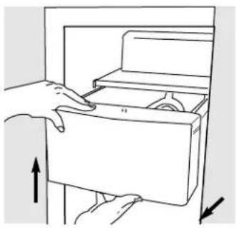
Line drawing of hands opening a refrigerator with an arrow indicating direction (no text or symbols)Ice Storage Drawer on Dispenser Models
To remove:
Set the icemaker power switch to the O (off) position. Pull the drawer straight out and then lift past the stop position.
To replace:
When replacing the drawer, be sure to press it firmly into place. If it does not go all the way back, remove it and rotate the drive mechanism 1/4 turn. Then push the drawer back again.
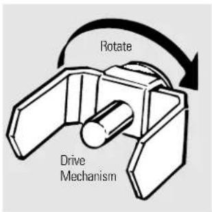
text_image
Rotate Drive MechanismCare and cleaning of the refrigerator.
natural_image
Simple line drawing of a curved, layered object resembling a tray or vent (no text or symbols)Dispenser drip area.

natural_image
Line drawing of a hand holding a small object, possibly a tool or device, with no visible text or symbols.Removing the dispenser pad (on some models)
Cleaning the Outside
The dispenser drip area, beneath the grille, should be wiped dry. Water left in this area may leave deposits. Remove the deposits by adding undiluted vinegar to the well. Soak until the deposits disappear or become loose enough to rinse away.
The dispenser pad/cradle (on dispenser models). Before cleaning, open the freezer door part way to prevent dispensing of ice or water when cleaning. On models with a dispenser pad, the pad can be removed before cleaning. Simply peel the pad away from the back wall of the dispenser. Clean the pad/cradle with a warm water and baking soda solution—about 15 ml of baking soda to 1 liter of water. Rinse thoroughly and wipe dry. To replace the pad, tuck the edges of the pad in the grooves on the back wall of the dispenser. Make sure that the top of the pad goes behind the dispenser collar.
The door handles and trim. Clean with a cloth dampened with soapy water. Dry with a soft cloth.
Keep the outside clean. Wipe with a clean cloth lightly dampened with kitchen appliance wax or mild liquid dish detergent. Dry and polish with a clean, soft cloth.
Do not wipe the refrigerator with a soiled dish cloth or wet towel. These may leave a residue that can erode the paint. Do not use scouring pads, powdered cleaners, bleach or cleaners containing bleach because these products can scratch and weaken the paint finish.
Cleaning the Inside
To help prevent odors, leave an open box of baking soda in the refrigerator and freezer compartments.
Unplug the refrigerator before cleaning. If this is not practical, wring excess moisture out of sponge or cloth when cleaning around switches, lights or controls.
Use warm water and baking soda solution—about 15 ml of baking soda to one liter of water. This both cleans and neutralizes odors. Rinse and wipe dry.
Use of any cleaning solution other than that which is recommended, especially those that contain petroleum distillates, can crack or damage the interior of the refrigerator.
Avoid cleaning cold glass shelves with hot water because the extreme temperature difference may cause them to break. Handle glass shelves carefully. Bumping tempered glass can cause it to shatter.
Do not wash any plastic refrigerator parts in the dishwasher.
The chill/thaw tray is dishwasher safe.
Care and cleaning of the refrigerator.
Behind the Refrigerator
Be careful when moving the refrigerator away from the wall. All types of floor coverings can be damaged, particularly cushioned coverings and those with embossed surfaces.
Pull the refrigerator straight out and return it to position by pushing it straight in. Moving the refrigerator in a side direction may result in damage to the floor covering or refrigerator.
When pushing the refrigerator back, make sure you don't roll over the power cord or icemaker supply line.
Preparing for Vacation
For long vacations or absences, remove food and unplug the refrigerator. Clean the interior with a baking soda solution of 15 ml of baking soda to 1 liter of water. Leave the doors open.
Set the icemaker power switch to the 0 position and shut off the water supply to the refrigerator.
If the temperature can drop below freezing, have a qualified servicer drain the water supply system to prevent serious property damage due to flooding.
Preparing to Move
Secure all loose items such as shelves and drawers by taping them securely in place to prevent damage.
When using a hand truck to move the refrigerator, do not rest the front or back of the refrigerator against the hand truck. This could damage the refrigerator. Handle only from the sides of the refrigerator.
Be sure the refrigerator stays in an upright position during moving.
Replacing the light bulbs.
Setting the controls to 0 (off) does not remove power to the light circuit.
text_image
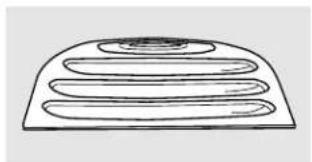
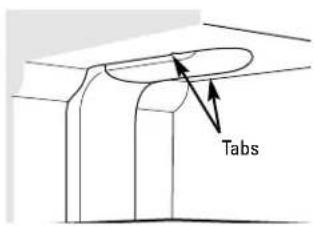
TabsRefrigerator Compartment—Upper Light
1 Unplug the refrigerator.
2 The bulbs are located at the top of the compartment, inside the light shield. Remove the screw at the front of the light shield.
3 To remove the light shield, press in on the tabs on the sides of the shield and slide forward and out.
4 After replacing the bulb with an appliance bulb of the same or lower wattage, replace the light shield and screw. When replacing the light shield, make sure that the tabs at the back of the shield fit into the slots at the back of the light shield housing.
⑤ Plug the refrigerator back in.
natural_image
Line drawing of a kitchen appliance with a handle and side panel, no text or symbols presentRefrigerator Compartment—Lower Light
This light is located above the top drawer.
1 Unplug the refrigerator.
2 Remove the convertible meat drawer control knob by pulling straight out.
3 Lift the light shield up and pull it out.
4 After replacing the bulb with an appliance bulb of the same or lower wattage, replace the shield and the knob.
⑤ Plug the refrigerator back in.
natural_image
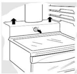
Line drawing of a vehicle rear view showing roof, side-mounted sensors, and dashboard (no text or symbols)Freezer Compartment
① Unplug the refrigerator.
2 Remove the shelf just above the light shield. (The shelf will be easier to remove if it is emptied first.) On some models, a screw at the top of the light shield will need to be removed.
3 To remove the light shield, press in on the sides, and lift up and out.
4 Replace the bulb with an appliance bulb of the same or lower wattage, and reinstall the light shield. When reinstalling the light shield, make sure the top tabs snap securely into place. Replace the screw (on some models).
⑤ Reinstall the shelf and plug the refrigerator back in.
Dispenser
① Unplug the refrigerator.
2 The bulb is located on the dispenser under the control panel. Remove the light bulb by turning it counterclockwise.
3 Replace the bulb with a bulb of the same size and wattage.
4 Plug the refrigerator back in.
For Built-In Style models
Read these instructions completely and carefully.

Before You Begin
Some models are equipped with trim kits that allow you to install door panels.
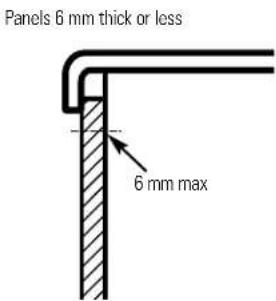
Panels less than 6 mm thick
When installing wood panels less than 6 mm thick, you need to create a filler panel, such as 3 mm cardboard, that will fit between the face of the door and the wood panel. If you are installing the pre-cut decorator panels, pre-cut filler panels are included in the kit. The combined thickness of the decorator or wood panel and the filler panel should be 6 mm.
text_image
Panels 6 mm thick or less 6 mm max19 mm or Raised Panel
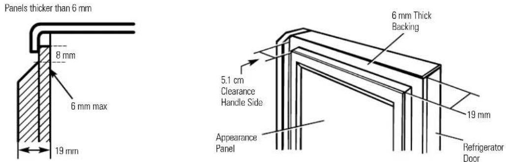
A raised panel design screwed or glued to a 6 mm thick backing, or a 19 mm routed board can be used. The raised portion of the panel must be fabricated to permit clearances of at least 5.1 cm from the handle side for fingertip clearance.
Panels thicker than 6mm, up to 19 mm max, will require that the outer 8 mm of panel perimeter be no thicker than 6 mm.
Weight limitations for custom panels: Refrigerator Door 17 kg max. Freezer Door 13 kg max.
text_image
Panels thicker than 6 mm 8 mm 6 mm max 19 mm 6 mm Thick Backing 5.1 cm Clearance Handle Side Appearance Panel 19 mm Refrigerator DoorDimensions for Custom Wood Panels
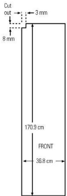
Freezer Panel
Without Dispenser
text_image
Cut out 8 mm 3 mm 170.9 cm FRONT 36.8 cmFreezer Panel
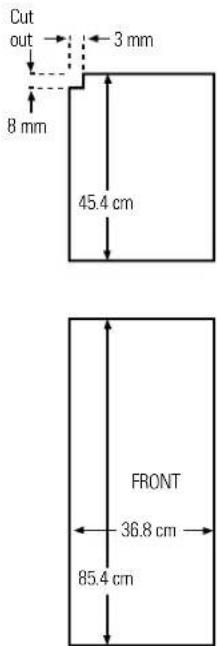
With Dispenser
text_image
Cut out 8 mm 3 mm 45.4 cm FRONT 36.8 cm 85.4 cmRefrigerator Panel
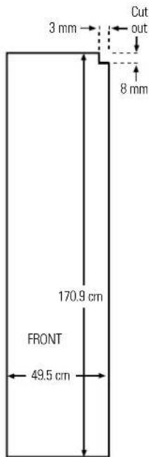
text_image
3 mm Cut out 8 mm 170.9 cm FRONT 49.5 cmThe areas at the top of the panels need to be cut out of the panels.
Read these instructions completely and carefully.
Insert the Freezer Panel and Refrigerator Panel.
Carefully push the freezer panel in until it slides into the slot behind the door handle. Push the filler panel (required with some door panels) in behind the decorator panel. Repeat for refrigerator panel.
If your model has a dispenser, this step only applies to the refrigerator panel and top freezer panel.
2 Insert the Bottom Freezer Panel (on dispenser models).
Carefully push the panel in until it slides into the slot behind the door handle. Push the filler panel
(required with some door panels) in behind the decorator panel.
3 Attach the Top Trim on the Freezer and Refrigerator Doors.
The Top Trim can be found inside the refrigerator compartment.
With a T-20 Torxdriver, attach the Top Trim, using two screws on each Top Trim piece, to the top of
each door. Hand tighten only. Make sure that the top of each panel fits snugly behind the lip of the Top Trim.
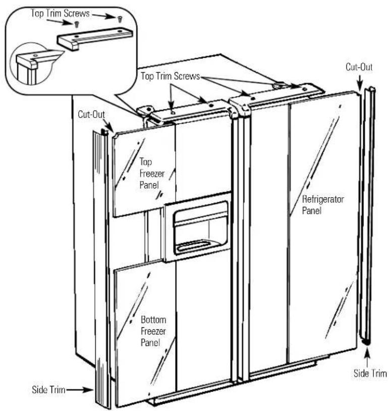
text_image
Top Trim Screws Top Trim Screws Cut-Out Top Freezer Panel Bottom Freezer Panel Side Trim Cut-Out Refrigerator Panel Side Trim4 Install the Side Trim.
These pieces are tucked inside the refrigerator door handle.
Do not remove the protective film on the outside of the Side Trim until the Side Trim is installed.
Fit the bottom of the Side Trim under the Bottom Trim as illustrated.
Hold the Side Trim against the front face of the decorator panels and fit the Side Trim under the Top Trim. Make sure the Side Trim is fitted correctly and that you are satisfied with the appearance of all the parts.
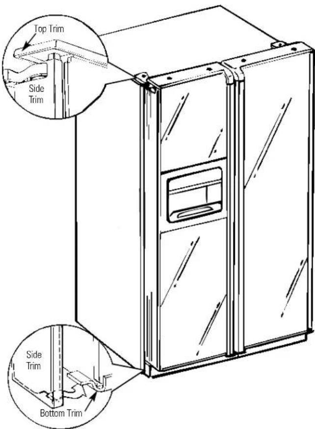
text_image
Top Trim Side Trim Side Trim Bottom TrimWhen installing or moving the refrigerator, the doors may need to be removed in order to fit the refrigerator through a doorway.
Removing the Doors
Make sure the doors are closed and the refrigerator is unplugged.
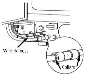
1 Disconnect water line and wiring harness.
Near the lower hinge on the freezer side, push in on the collars at each end of the coupling, and pull the water line tubing from the coupling. Also, disconnect wiring harness. Pull the water line and the harness through the lower rail.
2 Remove the hinge covers and the hinges.
In order to access the hinges, the hinge covers need to be removed. Remove the cover by grasping it on the sides, near the back of the cover. Push back on the cover and lift up at the back, then the front.
NOTE: DO NOT use a screwdriver to remove the cover. BE CAREFUL not to break the rear retaining tab on the hinge cover. Remove the hinges using a Torx T-20.
3 Remove the doors.
Carefully rotate the door to 90°. Guiding the disconnected water line and wiring harness, lift the door straight up.
NOTE: Not lifting the door straight up may damage the bottom hinge. Place doors on a protected surface.
NOTE: Be careful not to pinch the water tubing and the wire harness at the bottom of the door.
NOTE: Do not allow the connector to contact the floor. Hard contact can damage the connector. See "Replacing the Doors."
Replacing the Doors
Place doors on bottom hinges.
With the door at 90°, lower the door straight down onto the bottom hinge. Carefully close the door.
NOTE: Not lowering the door straight down onto the bottom hinge may damage the hinge.
NOTE: Do not allow the connector to contact the floor. Hard contact can damage the connector.
2 Replace top hinges and hinge covers.
Reinstall the top hinges using a Torx T-20. Replace the hinge covers. If the doors are not level, adjust the bottom right hinge with a 7/16"open ended wrench.
3 Reconnect water line and wiring harness.
Insert water tubing back into coupling, making sure the tubing is pushed far enough into the coupling so that you no longer see the mark on the tubing. Reconnect the wiring harness.
4 Turn on the water supply and plug the refrigerator back in.
text_image
Wire Harness Collars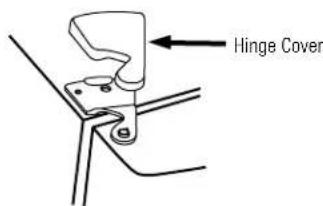
text_image
Hinge Cover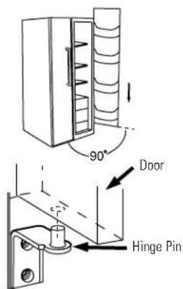
text_image
90° Door Hinge Pin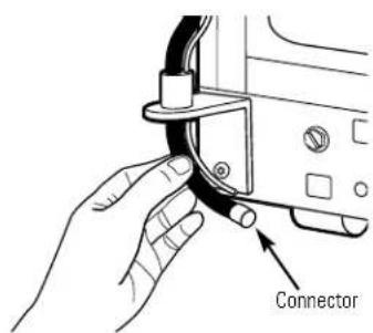
text_image
ConnectorInstallation Instructions
Refrigerator
Models 21, 23, 25, 27 & 29
BEFORE YOU BEGIN
Read these instructions completely and carefully.
- IMPORTANT – Save these instructions for local inspector's use.
- IMPORTANT – Observe all governing codes and ordinances.
- Note to Installer – Be sure to leave these instructions with the Consumer.
- Note to Consumer – Keep these instructions for future reference.
- Skill level – Installation of this appliance requires basic mechanical skills.
- Completion time – Refrigerator Installation 15 minutes
- Proper installation is the responsibility of the installer.
- Product failure due to improper installation is not covered under the Warranty.
WATER SUPPLY TO THE ICEMAKER (ON SOME MODELS)
If the refrigerator has an icemaker, it will have to be connected to a cold water line. An approved water supply kit is available at extra cost from your local distributor.
Maximum permissible inlet water pressure–8.2 bars. Minimum permissible inlet water pressure–2.8 bars.
Installation of the icemaker must be done by a qualified service technician.
REFRIGERATOR LOCATION
- Do not install the refrigerator where the temperature will go below 16^ because it will not run often enough to maintain proper temperatures.
- Do not install the refrigerator where the temperature will go above 37^ because it will not perform properly.
- Install it on a floor strong enough to support it fully loaded.
CLEARANCES
Allow the following clearances for ease of installation, proper air circulation and plumbing and electrical connections:
21' and 23' 25', 27' and 29'
- Sides 4 mm 4 mm
• Top25 mm 25 mm - Back 13 mm 25 mm
DIMENSIONS
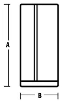
| 29 | 27 | 25 | 23 | 21 | |
| A* | 1733 mm | 1733 mm | 1733 mm | 1733 mm | 1733 mm |
| B | 908 mm | 908 mm | 908 mm | 908 mm | 908 mm |
| C** | 912 mm | 879 mm | 879 mm | 738 mm | 738 mm |
| D | 1261 mm | 1271 mm | 1271 mm | 1156 mm | 1156 mm |
| E | 1273 mm | 1255 mm | 1247 mm | 1232 mm | 1214 mm |
| F | 1051 mm | 1093 mm | 1099 mm | 989 mm | 986 mm |
| G | 1386 mm | 1381 mm | 1381 mm | 1361 mm | 1355 mm |
| H | 1140 mm | 1150 mm | 1149 mm | 1023 mm | 994 mm |
*Height does not include hinge.
**Depth includes handle.
text_image
A B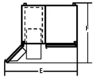
text_image
F E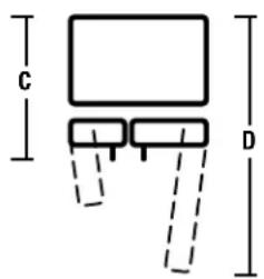
text_image
C D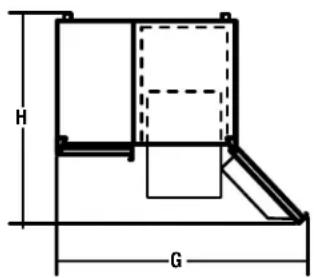
text_image
H GROLLERS
The rollers have 3 purposes:
■ Rollers adjust so the door closes easily when opened about halfway. [Raise the front about 5/8" (16 mm) from the floor.]
■ Rollers adjust so the refrigerator is firmly positioned on the floor and does not wobble.
■ Rollers allow you to move the refrigerator away from the wall for cleaning.
Final leveling adjustments should be made after the refrigerator has been installed.
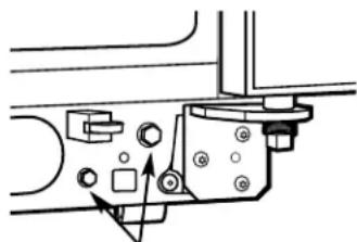
To adjust the rollers on 25', 27' and 29' models:
■ Turn the roller adjusting screws clockwise to raise the refrigerator, counterclockwise to lower it. Use a 3/8" hex socket or wrench, or an adjustable wrench.

natural_image
Technical line drawing of a mechanical assembly with no visible text or symbolsRoller adjusting screw
To adjust the rollers on 21' and 23' models:
Remove the base grille by opening the doors, removing the screws at each end, and pulling it straight out.
2 Turn the front roller adjusting screws clockwise to raise the refrigerator, counterclockwise to lower it. Use a 3/8" hex socket or wrench or an adjustable wrench.
natural_image
Mechanical assembly diagram showing a bracket with mounting holes and directional arrows (no text or labels)Roller adjusting screws
3 These models also have rear adjustable rollers so you can align the refrigerator with your kitchen cabinets. Use a long-handled 5/16" socket wrench to turn the screws for the rear rollers—clockwise to raise the refrigerator, counterclockwise to lower it.
4 Replace the base grille.
DOOR ALIGNMENT
After leveling, make sure that the refrigerator door is 1/16" higher than the freezer door.
To align the doors, adjust the refrigerator door.
Using a 7/16" socket wrench, turn the door adjusting screw to the right to raise the door, to the left to lower it. (A nylon plug, imbedded in the threads of the pin, prevents the pin from turning unless a wrench is used.)
2 After one or two turns of the wrench, open and close the refrigerator door and check the alignment at the top of the doors.
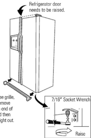
text_image
Refrigerator door needs to be raised. se grille, move end of and then ght out. 7/16" Socket Wrench RaiseTo remove the base grille, open the doors, remove the screw at each end of the base grille and then pull the grille straight out.
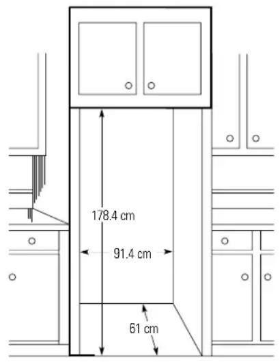
DIMENSIONS AND SPECIFICATIONS
(for Built-In Style models)
text_image
178.4 cm 91.4 cm 61 cm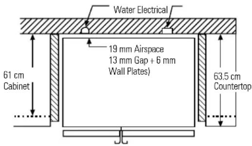
text_image
Water Electrical 19 mm Airspace 13 mm Gap + 6 mm Wall Plates) 61 cm Cabinet 63.5 cm CountertopINSTALLING THE WATER LINE
BEFORE YOU BEGIN
The water line installation is not warranted by the refrigerator or icemaker manufacturer. Follow these recommendations carefully to minimize the risk of expensive water damage.
Water hammer (water banging in the pipes) in house plumbing can cause damage to refrigerator parts and lead to water leakage or flooding. Call a qualified plumber to correct water hammer before installing the water supply line to the refrigerator.
To prevent burns and product damage, do not hook up the water line to the hot water line.
If you use your refrigerator before connecting the water line, make sure the icemaker power switch is in the O (off) position.
Do not install the icemaker tubing in areas where temperatures fall below freezing.
When using any electrical device (such as a power drill) during installation, be sure the device is insulated or wired in a manner to prevent the hazard of electric shock.
All installations must be in accordance with local plumbing code requirements.
Installation of the icemaker must be done by a qualified service technician.
WARNING!
Connect to potable
water supply only.
1 CONNECT THE TUBING TO THE REFRIGERATOR
NOTES:
- Before making the connection to the refrigerator, be sure the refrigerator power cord is not plugged into the wall outlet.
- We recommend installing a water filter if your water supply has sand or particles that could clog the screen of the refrigerator's water valve. Install it in the water line near the refrigerator.
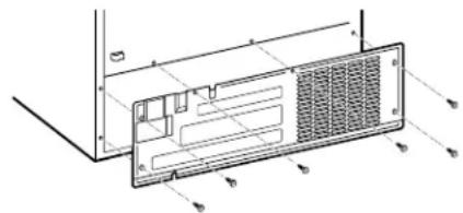
1 CONNECT THE TUBING TO THE REFRIGERATOR (CONT.)
Some models have the refrigerator connection at the end of tubing located outside the compressor compartment access cover. On other models, the compressor compartment access cover must be removed in order to access the refrigerator connection at the water valve.
text_image
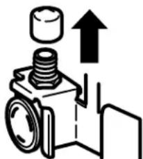
Technical diagram of a computer ventilation panel with labeled components and dimensionsOn models using the refrigeration connection at the water valve, remove the plastic flexible cap.
natural_image
Diagram of a mechanical assembly with a cylindrical component and an upward arrow, no text or symbols present.Place the compression nut and ferrule (sleeve) onto the end of the tubing as shown.
Insert the end of the tubing into the water valve connection as far as possible. While holding the tubing, tighten the fitting.
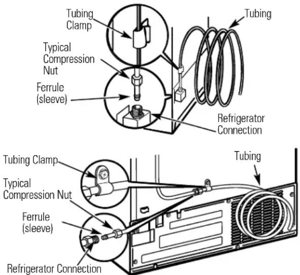
Fasten the tubing into the clamp provided to hold it in a vertical position. You may need to pry open the clamp.
One of the illustrations below will look like the connection on your icemaker.
text_image
Tubing Clamp Typical Compression Nut Ferrule (sleeve) Refrigerator Connection Tubing Typical Compression Nut Ferrule (sleeve) Refrigerator ConnectionReattach the access cover.
2 TURN THE WATER ON AND PLUG IN THE REFRIGERATOR
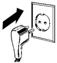
Arrange the coil of tubing so that it does not vibrate against the back of the refrigerator or against the wall. Push the refrigerator back to the wall.
natural_image
Diagram showing a plug inserted into an electrical outlet with a magnified view of the socket (no text or symbols)3 START THE ICEMAKER
Set the icemaker power switch to the I position. The icemaker will not begin to operate until it reaches its operating temperature of -9^ or below. It will then begin operation automatically if the icemaker power switch is in the I position.
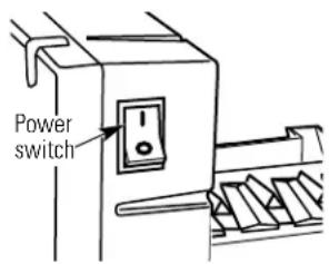
text_image
Power switchNOTE: In lower water pressure conditions, the water valve may turn on up to 3 times to deliver enough water to the icemaker.

Newer refrigerators sound different from older refrigerators. Modern refrigerators have more features and use newer technology.
Do you hear what I hear? These sounds are normal.
HUMMM... WHOOSH...
■ The new high efficiency compressor may run faster and longer than your old refrigerator and you may hear a high-pitched hum or pulsating sound while it is operating.
■ Sometimes the refrigerator runs for an extended period, especially when the doors are opened frequently. This means that the Frost Guard™ feature is working to prevent freezer burn and improve food preservation.
■ You may hear a whooshing sound when the doors close. This is due to pressure equalizing within the refrigerator.
■ You may hear the fans spinning at high speeds. This happens when the refrigerator is first plugged in, when the doors are opened frequently or when a large amount of food is added to the refrigerator or freezer compartments. The fans are helping to maintain the correct temperatures.
If either door is open for over 3 minutes, you may hear the fans come on in order to cool the light bulbs.
■ The fans change speeds in order to provide optimal cooling and energy savings.
■ You may hear the fan running after selecting one of the CustomCool™ settings.
CLICKS, POPS, CRACKS and CHIRPS
■ You may hear cracking or popping sounds when the refrigerator is first plugged in. This happens as the refrigerator cools to the correct temperature.
■ Electronic dampers click open and closed to provide optimal cooling and energy savings.
■ The compressor may cause a clicking or chirping sound when attempting to restart (this could take up to 5 minutes).
■ The electronic control board may cause a clicking sound when relays activate to control refrigerator components.
■ Expansion and contraction of cooling coils during and after defrost can cause a cracking or popping sound.
■ On models with an icemaker, after an icemaking cycle, you may hear the ice cubes dropping into the ice bucket.
WATER SOUNDS
■ The flow of refrigerant through the freezer cooling coils may make a gurgling noise like boiling water.
■ Water dropping on the defrost heater can cause a sizzling, popping or buzzing sound during the defrost cycle.
A water dripping noise may occur during the defrost cycle as ice melts from the evaporator and flows into the drain pan.
■ Closing the door may cause a gurgling sound due to pressure equalization.

For additional information on normal icemaker and dispenser operating sounds, see the About the automatic icemaker and About the ice and water dispenser sections.

Troubleshooting Tips Save time and money! Review the charts on the following pages first and you may not need to call for service.
| Problem Possible Causes | What To Do | |
| Refrigerator does not operate | Refrigerator in defrost cycle. | ·Wait about 30 minutes for defrost cycle to end. |
| Either or both controls set to 0 (off). | ·Set the controls to a temperature setting. | |
| Refrigerator is unplugged. | ·Push the plug completely into the outlet. | |
| The fuse is blown/circuit breaker is tripped. | ·Replace fuse or reset the breaker. | |
| The refrigerator is in showroom mode. | ·Unplug the refrigerator and plug it back in. | |
| Vibration or rattling (slight vibration is normal) | Rollers need adjusting. | ·See Rollers. |
| Motor operates for long periods or cycles on and off frequently. (Modern refrigerators with more storage space and a larger freezer require more operating time. They start and stop often to maintain even temperatures.) | Normal when refrigerator is first plugged in. cool down. | ·Wait 24 hours for the refrigerator to completely |
| Often occurs when large amounts of food are placed in refrigerator. | ·This is normal. | |
| Door left open. | ·Check to see if package is holding door open. | |
| Hot weather or frequent door openings. | ·This is normal. | |
| Temperature controls set at the coldest setting. | ·See About the controls. | |
| Refrigerator or freezer compartment too warm | Temperature control not set cold enough. | ·See About the controls. |
| Warm weather or frequent door openings. | ·Set the temperature control one step colder. See About the controls. | |
| Door left open. | ·Check to see if package is holding door open. | |
| Frost or ice crystals on frozen food (frost within package is normal) | Door left open. | ·Check to see if package is holding door open. |
| Too frequent or too long door openings. | ||
| Divider between refrigerator and freezer compartments feels warm | Automatic energy saver system circulates warm liquid around front edge of freezer compartment. | ·This helps prevent condensation on the outside. |
| Automatic icemaker does not work | Icemaker power switch is in the off position. | ·Set the power switch to the on position. |
| Water supply turned off or not connected. | ·See Installing the water line. | |
| Freezer compartment too warm. | ·Wait 24 hours for the refrigerator to completely cool down. | |
| Piled up cubes in the storage bin cause the icemaker to shut off. | ·Level cubes by hand. | |
| Ice cubes stuck in icemaker. (Green power light on icemaker blinking). | ·Turn off the icemaker, remove cubes and turn the icemaker back on. | |
Before you call for service...
| Problem Possible Causes | What To Do | |
| Frequent "buzzing" sound | Icemaker power switch is in the on position, but the water supply to the refrigerator has not been connected. | • Set the power switch to the off position. Keeping it in the on position will damage the water valve. |
| Ice cubes have odor/taste | Ice storage bin needs cleaning. | • Empty and wash bin. Discard old cubes. |
| Food transmitting odor/taste to ice cubes. | • Wrap foods well. | |
| Interior of refrigerator needs cleaning. | • See Care and cleaning. | |
| Small or hollow cubes | Water filter clogged. | • Replace filter cartridge with new cartridge or with plug. |
| Slow ice cube freezing | Door left open. | • Check to see if package is holding door open. |
| Temperature control not set cold enough. | • See About the controls. | |
| Cube dispenser does not work | Icemaker turned off or water supply turned off. | • Turn on icemaker or water supply. |
| Ice cubes are frozen to icemaker feeler arm. | • Remove cubes. | |
| Irregular ice clumps in storage container. | • Break up with fingertip pressure and discard remaining clumps.• Freezer may be too warm. Adjust the freezer control to a colder setting, one position at a time, until clumps do not form. | |
| Dispenser is LOCKED. | • Press and hold the LOCK CONTROL pad for 3 seconds. | |
| Water has poor taste/odor | Water dispenser has not been used for a long time. | • Dispense water until all water in system is replenished. |
| Water in first glass is warm | Normal when refrigerator is first installed. | • Wait 24 hours for the refrigerator to completely cool down. |
| Water dispenser has not been used for a long time. | • Dispense water until all water in system is replenished. | |
| Water system has been drained. | • Allow several hours for replenished supply to chill. | |
| Water dispenser does not work | Water supply line turned off or not connected. | • See Installing the water line. |
| Water filter clogged. | • Replace filter cartridge or remove filter and install plug. | |
| Air may be trapped in the water system. | • Press the dispenser arm for at least two minutes. | |
| Dispenser is LOCKED. | • Press and hold the LOCK CONTROL pad for 3 seconds. | |
| Water spurting from dispenser | Newly-installed filter cartridge. | • Run water from the dispenser for 3 minutes (about six liters). |
| Water is not dispensed but icemaker is working | Water in reservoir is frozen. | • Call for service. |
| Refrigerator control setting is too cold. | • Set to a warmer setting. | |
| No water or ice cube production | Supply line or shutoff valve is clogged. | • Call a plumber. |
| Water filter clogged. | • Replace filter cartridge or remove filter and install plug. | |
| Dispenser is LOCKED. | • Press and hold the LOCK CONTROL pad for 3 seconds. | |
| CUBED ICE was selected but CRUSHED ICE was dispensed | Last setting was CRUSHED ICE. | A few cubes were left in the crusher from the previous setting. This is normal. |
| Orange glow in the freezer | Defrost heater is on. | This is normal. |
| Refrigerator has odor | Foods transmitting odor to refrigerator. | Foods with strong odors should be tightly wrapped.Keep an open box of baking soda in the refrigerator; replace every three months. |
| Interior needs cleaning. | See Care and cleaning. | |
| Door not closing properly | Door gasket on hinge side sticking or folding over. | Apply paraffin wax to the face of the gasket. |
| A door bin is hitting a shelf inside the refrigerator. | Move the door bin up one position. | |
| Moisture forms on outside of refrigerator | Not unusual during periods of high humidity. | Wipe surface dry. |
| Moisture collects inside (in humid weather, air carries moisture into refrigerator when doors are opened) | Too frequent or too long door openings. | |
| Interior light does not work | No power at outlet. | Replace fuse or reset the breaker. |
| Light bulb burned out. | See Replacing the light bulbs. | |
| Water on kitchen floor or on bottom of freezer | Cubes jammed in chute. | Poke ice through with a wooden spoon. |
| Hot air from bottom of refrigerator | Normal air flow cooling motor.In the refrigeration process, it is normal that heat be expelled in the area under the refrigerator. Some floor coverings are sensitive and will discolor at these normal and safe temperatures. | |
| Refrigerator never shuts off but the temperatures are OK | Adaptive defrost keeps compressor running during door openings. | This is normal. The refrigerator will cycle off after the door remains closed for 2 hours. |
| Refrigerator beeping | Door open. | Close door. |
| Food isn't thawing/chilling | Packaging. | Increase time or re-package in plastic. |
| Wrong weight selected. | Select a larger weight. | |
| Item with high fat content. | Select a larger weight. | |
| Not using Chill/Thaw tray. | Place items on tray and allow space in between items for better air flow. | |
| Actual temperature not equal to Set temperature | Unit just plugged in. | Allow 24 hours for system to stabilize. |
| Door open for too long. | Allow 24 hours for system to stabilize. | |
| Warm food added to refrigerator. | Allow 24 hours for system to stabilize. | |
| Defrost cycle is in process. | Allow 24 hours for system to stabilize. | |
| Select Temp feature is not working | Refrigerator compartment temperature control is set at warmest setting. | This is normal. In order to minimize energy usage, the Select Temp feature is disabled when the refrigerator temperature control is set at the warmest setting. |
(in addition to other information in Owner's Manual)

IMPORTANT SAFETY INSTRUCTIONS
To reduce the risk of personal injury or damage to property, follow basic safety precautions when using this refrigerator, including the following:
When using any Electrical Product, basic precautions should always be followed, including the following:
READ THESE INSTRUCTIONS CAREFULLY BEFORE USING THE REFRIGERATOR. KEEP THE INSTRUCTIONS HANDY FOR FUTURE REFERENCE.
IMPORTANT: Always operate the refrigerator from a power source of the same Voltage, Frequency and Rating as indicated on the refrigerator identification plate. Operate the refrigerator from an Earthed (Grounded) 3 pin power outlet fully accessible when the refrigerator is located in its normal operating position.
■ Close supervision is necessary when any electrical product is used by or operated near children or infirm persons; young children should be supervised to ensure that they do not play with the refrigerator.
IMPORTANT: Do not operate the refrigerator with a damaged Supply cord or Plug. If it is damaged it must be replaced by the manufacturer, distributor or its service agent or a similarly qualified person in order to avoid a hazard. Special tools are required to replace the Supply flexible cord.
■WARNING: Avoid the use of extension cords. If it is necessary to use an extension cord, prior to its use, make sure the extension cord is safe to use, capable of handling the electrical load of the product (refer to Product identification plate) and has been checked and tested by your electricity supplier or a qualified technician.
To avoid becoming entangled in the cord, never lay it through or along a walkway or thoroughfare.
Do not allow the cord to hang over the edge of a bench top where it may be grabbed by children or become entangled with the user.
Installing the Water Line
For Australian and New Zealand installation, read these instructions completely and carefully.
Before You Begin
IMPORTANT: Government legislation and Codes in most States and Territories of Australia require installation by a licensed plumber. The installation must conform to Australian Standard AS 3500.1 Water supply.
Water hammer (water banging in the pipes) in house plumbing can cause damage to the refrigerator parts and lead to water leakage or flooding. Call a qualified plumber to correct water hammer before installing the water supply line to the refrigerator.
To prevent burns and refrigerator damage, do not hook up the water line to the hot water line.
If you use your refrigerator before connecting the water line, make sure the icemaker power switch is set to the 0 position.
Do not install the icemaker tubing in areas where the temperatures fall below freezing.
Shut Off the Main Water Supply
For models fitted with an icemaker, a water supply kit (containing flexible tubing and fittings) is supplied with the refrigerator.
The water pressure must be between 138 and 827 kPa on models without a water filter fitted and between 275 and 827 kPa on models with a water filter fitted.
Turn Off the water and open a low tap to drain the water from the pipe.
Complying with the plumbing codes, install a suitable branch fitting (not supplied) to the cold water supply.
Extend the branch to a suitable location adjacent to the refrigerator when it is located in its operating position. Terminate the branch with a shutoff valve (not supplied).
IMPORTANT: The shut-off valve should be accessible (such as in an adjacent cupboard, as close to the wall as possible) when the refrigerator is in its normal operating position.
If your water supply pressure is higher than 690 kPa during the day (if so, it may reach higher levels at night), install a suitable Pressure limiting valve (not supplied), after the shut-off valve, making sure the “flow arrows” on the body of the device face the same direction as the water flow.
If necessary, assemble a suitable fitting (not supplied) to the up-stream end of the shutoff valve (or pressure limiting valve) for attachment of the fitting supplied with the water supply kit.
NOTE: PTFE tape should be used for a water tight seal when assembling all the above fittings.
Do not turn the water supply On at this time.
Special Installation Instructions for Australia and New Zealand.
Installing the Water Line (cont.)
Connecting the Tubing to the Shutoff Valve
Attach the fitting with the male thread supplied with the water supply kit to the shutoff valve (or pressure limiting valve, if fitted), and tighten.
NOTE: PTFE tape should be used for a water tight seal when assembling all the above fittings.
Route the tubing through a hole drilled in the side of the cupboard as close to the wall as possible.
Make sure there is sufficient length of tubing [approximately 240 cm coiled into 3 turns of approximately 25 cm] to allow the refrigerator to move out from the wall after installation.
Insert and push the end of the tubing into the fitting as far as possible.
With the free end of the tubing located in a suitable container, turn the main water supply On and flush out the tubing until the water is clear.
Turn Off the shutoff valve after approximately 1 litre of water has been flushed through the tubing.
Connecting the Tubing to the Refrigerator
Before making the connection to the refrigerator, be sure the power is turned OFF and the power cord is disconnected from the Power Outlet.
If your refrigerator does not include a water filter, we recommend installing one in the water line near the refrigerator if your water supply has sand or particles that could clog the screen of the refrigerator's water valve.
Remove the refrigerator access cover.
Remove the plastic flexible cap from the water valve (refrigerator connection).
Attach the fitting with the female thread supplied with the water supply kit to the water valve and tighten.
Insert and push the end of the tubing into the fitting as far as possible.
Fasten the tubing into the clamp provided to hold it in position. You may need to pry open the clamp.
Turn the Water On
Turn the water On at the shutoff valve.
Tighten any connection that leaks.
Replace the access cover and tighten all screws (on some models).
Plug In the Refrigerator
Plug in the refrigerator to the Power Outlet and turn On.
IMPORTANT: Always operate the Refrigerator from a power source of the same Voltage, Frequency and Rating as indicated on the Refrigerator Identification Plate. Operate the Refrigerator from an Earthed (Grounded) 3 Pin Power Outlet fully accessible when the refrigerator is located in its normal operating position.
Arrange the coil of tubing so that it does not vibrate against the back of the refrigerator or against the wall.
Push the refrigerator back to the wall, making sure the power cord and the water line tubing are not trapped, entangled or squashed by the refrigerator (including the wheels) or wall.
Start the Icemaker
Set the icemaker power switch to the I position.
The icemaker will not begin to operate until it reaches its operating temperature of -9^ or below. It will then begin operation automatically if the icemaker power switch is in the I position.
NOTE: In lower water pressure conditions, the water valve may turn on up to 3 times to make sure enough water reaches the icemaker.
text_image
Power switchNotes.
Préparation ....63–65
text_image
-18 SET 3 SET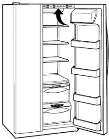
natural_image
Line drawing of a refrigerator interior showing shelves and doors (no text or symbols)natural_image
Line drawing of a refrigerator with shelves and doors open, showing internal storage compartments (no text or symbols)natural_image
Line drawing of an open refrigerator with shelves and a door, showing no text or symbolsnatural_image
Line drawing of a refrigerator drawer with shelves and compartments (no text or symbols)ExpressThaw™
natural_image
Line drawing of a refrigerator drawer with cylindrical objects inside (no text or symbols)ExpressChill™
Comment l'utiliser
natural_image
Two simple line drawings: a battery with internal structure and a droplet with raindrops inside a circle (no text or symbols)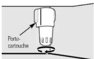
text_image
Porte- cartouchenatural_image
Technical line drawing of a door mechanism with internal compartments and directional arrows indicating movement (no text or symbols)natural_image
Line drawing of a mechanical device with internal grid structure (no text or symbols)natural_image
Pure technical line drawing of a mechanical component or assembly (no text or symbols)natural_image
Illustration of a tablet with two arrows pointing at it, no text or symbols presentnatural_image
Illustration of a stack of documents with a ruler and an arrow pointing to a document (no text or symbols present)Étagère QuickSpace™
natural_image
Line drawing of a hand holding a tray with a handle and scroll (no text or symbols)text_image
Diagram illustrating a mechanical or fluid system with labeled components and directional arrows indicating flow or movement.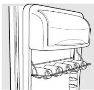
natural_image
Line drawing of a mechanical device with rollers and a top cover (no text or symbols)natural_image
Line drawing of a mechanical device with a magnified inset showing a ladder and lever mechanism (no text or symbols)Étagères et bacs.
natural_image
Technical line drawing of a mechanical bracket or support structure (no text or symbols)natural_image
Technical line drawing of a metal rack with a handle and support bracket (no text or symbols)text_image
Diagram showing two labeled parts of a mechanical device with arrows indicating direction or movement.text_image
Diagram showing a structural beam under load with directional arrows and numbered componentsnatural_image
Line drawing of a multi-tiered storage cabinet or rack unit (no text or symbols)natural_image
Simple line drawing of a circular object with internal divisions and two small symbols, no text or labels present.natural_image
Pure technical line drawing of a mechanical component or bracket (no text or symbols)natural_image
Line drawing of a mechanical or architectural component with layered surfaces and a folded panel (no text or symbols)natural_image
Simple line drawing of a plastic container with two upward arrows indicating flow or movement (no text or symbols)natural_image
Hand pouring liquid into a container with an arrow indicating flow (no text or symbols)natural_image
Simple icon of a key inside a circle with a dot above (no text or symbols)natural_image
Line drawing of hands opening a refrigerator drawer with an arrow indicating direction (no text or symbols)Tiroir à glace
natural_image
Simple line drawing of a three-tiered oval object with concentric layers (no text or symbols)natural_image
Line drawing of a hand holding a small container with a handle, no text or symbols presentnatural_image
Line drawing of a kitchen appliance with a valve and handle (no text or symbols)natural_image
Simple line drawing of a vehicle rear view with roof and side-mounted sensors (no text or symbols)natural_image
Simple line drawing of a rectangular frame with vertical and horizontal lines, labeled 'A' at the top left (no other text or symbols)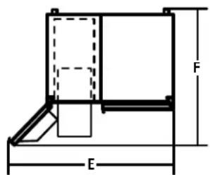
text_image
F E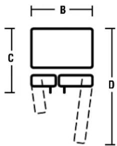
text_image
B C D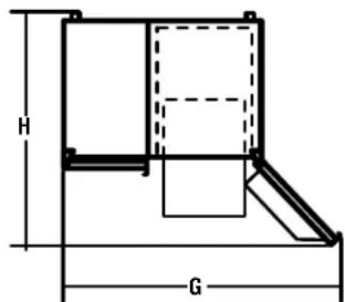
text_image
H GROULETTES
text_image
Technical diagram of a computer ventilation panel with labeled components and directional arrows indicating assembly or movement.1 BRANCHEZ LE TUYAU À VOTRE RÉFRIGÉRATEUR (SUITE)
natural_image
Mechanical assembly diagram showing a bolt and cylinder with an upward arrow (no text or labels)natural_image
Diagram showing a plug inserted into an electrical outlet with a magnified view of the socket (no text or symbols)3 METTEZ EN MARCHE LA MACHINE À GLAÇONS
text_image
-18 SET 3 SET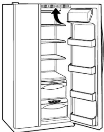
natural_image
Line drawing of an open refrigerator with shelves and a door, showing no text or symbolsnatural_image
Line drawing of an open refrigerator with shelves and doors, no text or symbols presentnatural_image
Line drawing of a refrigerator with shelves and door, showing front panel open (no text or symbols)natural_image
Line drawing of a refrigerator drawer with shelves and doors (no text or symbols)natural_image
Line drawing of a refrigerator drawer with four cylindrical batteries (no text or symbols)ExpressChill™ (Refrigeración Rápida)
Cómo utilizarlo
natural_image
Two technical illustrations: top shows a cylindrical battery with internal ports, bottom shows a droplet with liquid droplets (no text or symbols)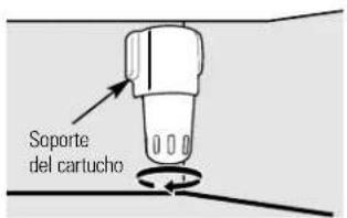
natural_image
Technical line drawing of a mechanical component with internal channels and directional arrows (no text or symbols)natural_image
Technical line drawing of a mechanical component with internal grid structure (no text or symbols)Recipiente abatible del congelador
natural_image
Pure mechanical diagram showing a folded paper or sheet with an arrow indicating direction (no text or symbols)natural_image
Abstract diagram with black arrows pointing upward and downward, no text or symbols presentnatural_image
Illustration of stacked documents with a black arrow pointing to one document (no text or symbols present)Estante QuickSpace™
natural_image
Line drawing of a hand holding a flatboard with a handle, no text or symbols presenttext_image
Diagram showing two labeled parts (① and ②) with directional arrows indicating movement or flow between them.
natural_image
Line drawing of a mechanical device with rollers and a top panel (no text or symbols)natural_image
Line drawing of a mailbox with a ladder and support structure (no text or symbols)natural_image
Technical line drawing of a mechanical component with spring-like extensions (no text or symbols)natural_image
Technical line drawing of a metal rack with a handle and support bracket (no text or symbols)text_image
Diagram showing two labeled parts of a mechanical device with arrows indicating direction or movementtext_image
Diagram showing a ladder structure with directional arrows and numbered components, likely illustrating a physics or engineering concept.natural_image
Line drawing of a multi-tiered refrigerator shelf with no text or symbolsnatural_image
Simple diagram of a circular structure with two labeled points and curved arrows, no text or symbols present.Recipiente convertible para carnes
natural_image
Technical line drawing of a mechanical component with an arrow indicating motion (no text or symbols)natural_image
Simple line drawing of a container with two arrows pointing upward (no text or symbols)natural_image
Line drawing of a mechanical assembly with folded components (no text or symbols)natural_image
Line drawing of hands opening a refrigerator drawer with an arrow indicating direction (no text or symbols)natural_image
Simple line drawing of a three-tiered oval object with concentric layers (no text or symbols)natural_image
Hand holding a small cylindrical object with a handle, no visible text or symbolsnatural_image
Line drawing of a kitchen appliance with a handle and side panel, no text or symbols presentnatural_image
Simple line drawing of a mechanical component or bracket with no text or symbolsCompartimento del congelador
Modelos 21, 23, 25, 27 y 29
ANTES DE INICIAR
natural_image
Simple line drawing of a rectangular frame with vertical and horizontal lines, labeled 'A' on the left side (no text or symbols within the diagram itself)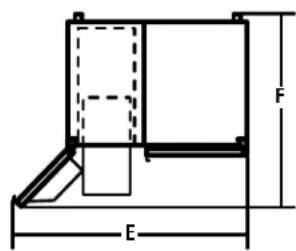
text_image
F E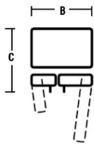
text_image
B C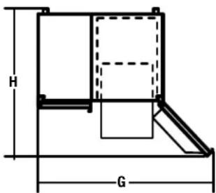
text_image
H GRODILLOS
natural_image
Technical line drawing of a mechanical assembly with no visible text or symbolsTornillo del rodillo ajustando
natural_image
Mechanical assembly diagram showing components and alignment (no text or labels)text_image
Technical diagram of a computer ventilation panel with labeled components and dimension linesnatural_image
Pure mechanical diagram showing a valve or actuator with an upward arrow, no text or symbols present.① CONECTE EL TUBO AL FRIGORÍFICO (CONT.)
natural_image
Diagram showing a plug inserted into an electrical outlet with a magnified view of the socket (no text or symbols present)3 PONGA EN MARCHA EL DISPOSITIVO PARA HACER HIELO
text_image
-18 SET 3 SET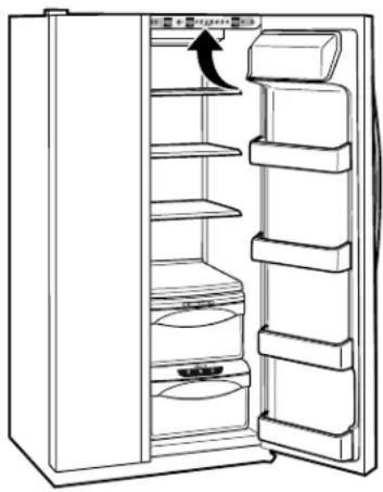
natural_image
Line drawing of an open refrigerator with shelves and a door, showing no text or symbolsnatural_image
Line drawing of an open refrigerator with shelves and a door, showing no text or symbolsnatural_image
Line drawing of a refrigerator with shelves and door, showing front panel open (no text or symbols)natural_image
Line drawing of a refrigerator drawer with shelves and a door (no text or symbols)ExpressThaw™ (Scongelamento veloce)
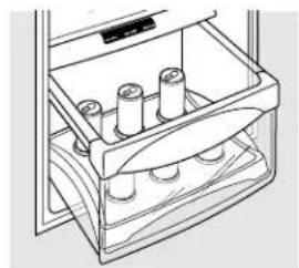
natural_image
Line drawing of a drawer with multiple cylindrical objects inside (no text or symbols)ExpressChill™ (Raffreddamento veloce)
Come si usa:
natural_image
Two technical illustrations: top shows a cylindrical container with internal slots, bottom shows a droplet with liquid drops (no text or symbols)natural_image
Diagram of a refrigerator interior showing internal compartments and directional arrows indicating movement (no text or labels)natural_image
Line drawing of a mechanical component with internal grid structure (no text or symbols)Contenitore inclinabile del freezer
natural_image
Pure mechanical diagram showing a lever and pivot point without any text or symbolsPremere la levetta
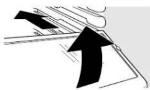
natural_image
Pure technical diagram showing mechanical components without any text, numbers, or symbolsnatural_image
Illustration of stacked documents with a black arrow pointing to one document (no text or symbols present)natural_image
Line drawing of a mechanical device with a handle and lever (no text or symbols)text_image
Diagram showing two labeled mechanical or fluid flow paths with arrows indicating direction and movement, marked with numbers ① and ②.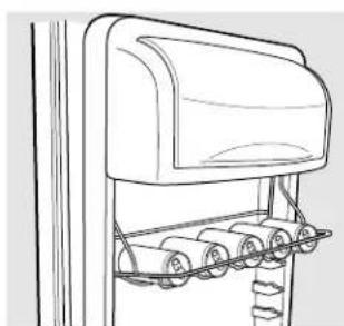
natural_image
Line drawing of a mechanical device with rollers and a top cover (no text or symbols)natural_image
Line drawing of a mailbox with a handbag and base mount (no text or symbols)natural_image
Technical line drawing of a mechanical component with ribbed structure (no text or symbols)Cestelli del freezer
natural_image
Technical line drawing of a metal rack with a black bracket and vertical supports (no text or symbols)text_image
Diagram showing two labeled parts of a mechanical device with arrows indicating direction or movementtext_image
Diagram showing a ladder structure with directional arrows and numbered components, likely illustrating a physics or engineering concept.Riempimento del freezer
natural_image
Line drawing of a multi-tiered storage cabinet or rack unit (no text or symbols)natural_image
Simple line drawing of a sphere with two circular elements and curved arrows, no text or symbols present.natural_image
Pure technical line drawing of a mechanical component or bracket (no text or symbols)natural_image
Simple line drawing of a container with two upward arrows indicating flow or movement (no text or symbols)natural_image
Line drawing of hands opening a refrigerator drawer with an arrow indicating direction (no text or symbols)natural_image
Simple line drawing of a three-tiered dome-shaped object with no text or symbolsnatural_image
Line drawing of a hand holding a cylindrical object with a handle, no text or symbols presentCopertura leva dispenser
natural_image
Line drawing of a kitchen appliance with a handle and valve (no text or symbols)Comparto frigorifero-luce inferiore
natural_image
Simple line drawing of a container with handles and a side table, no text or symbols presentComparto freezer
Modelli 21, 23, 25, 27 e 29
PRIMA DI INIZIARE
natural_image
Technical line drawing of a mechanical assembly with no visible text or symbolsnatural_image
Mechanical assembly diagram showing components and alignment (no text or labels)natural_image
Technical diagram of a computer ventilation panel with labeled components (no text or symbols present)natural_image
Pure mechanical diagram showing a piston and cylinder with an upward arrow, no text or symbols presentnatural_image
Diagram showing a plug inserted into an electrical outlet with a magnified view of the socket (no text or symbols)3 ACCENDETE IL FABBRICATORE DI GHIACCIO
TINTINNII, SCOPPIETTII, SCRICCHIOLII e STRIDII
text_image
-18 SET 3 SET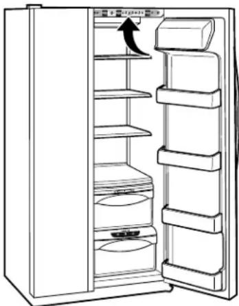
natural_image
Line drawing of an open refrigerator with shelves and a door, showing no text or symbolsnatural_image
Line drawing of a refrigerator with shelves and doors open, showing an arrow indicating the door handle (no text or symbols present)natural_image
Line drawing of a refrigerator with shelves and doors open (no text or symbols)■ Peitos de galinha (1,0 kg)
Picadinho de carne (1,0 kg)
Bife (1,0 kg)
1,50 kg (12 horas)
■ Peitos de galinha (1,5 kg)
Picadinho de carne (1,5 kg)
Bife (1,5 kg)
15 minutos
■1 lata de bebida (355 ml)
■2 sucos de caixinha (175–240 ml cada)
30 minutos
2 a 6 latas de bebida (355 ml cada)
■2 garrafas plásticas de bebida de 590 ml
4 a 6 sucos de caixinha (175–240 ml cada)
■3 pacotes de suco de folha de alumínio
Vinho (garrafa de 750 ml)
45 minutos
■2 litros de bebida
■1,9 litro de suco
Gelatina - 1 pacote
Ajuste Cítrico (6°C)
Laranjas, limões, limas, abacaxi, melão cantalupo
Feijões, pepinos, tomates, pimentas, beringela, abóbora
Ajuste Safra (1°C)
Morangos, framboesas, kiwi, peras, cerejas, amoras, uvas, ameixas, nectarinas, maçãs
Aspargos, brócolis, milho, cogumelos, espinafre, couve-flor, couve, cebolinha, beterraba, cebolas
Ajuste Carne (-1°C)
natural_image
Two technical illustrations: top shows a cylindrical device with internal components, bottom shows a droplet with liquid drops (no text or symbols)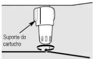
text_image
Suporte do cartuchonatural_image
Technical line drawing of a mechanical component with internal gear-like structure and directional arrows indicating motion (no text or symbols)natural_image
Technical line drawing of a mechanical component with internal grid structure (no text or symbols)natural_image
Pure technical line drawing of a mechanical component with no text or symbolsnatural_image
Abstract line drawing with black arrows pointing upward and downward, no text or symbols presentPrateleira que desliza para fora, à prova de transbordamentos
natural_image
Illustration of a rolled-up document or scroll with a black arrow pointing to it (no text or symbols present)Prateleira QuickSpace™
natural_image
Line drawing of a mechanical device with rollers and a handle (no text or symbols)text_image
Diagram showing two labeled mechanical or fluid flow paths with directional arrows and numbered components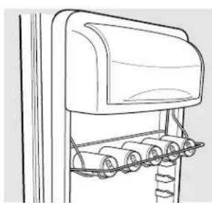
natural_image
Line drawing of a mechanical device with rollers and a top cover (no text or symbols)natural_image
Line drawing of a mailbox with a magnified inset showing the handle (no text or symbols)natural_image
Technical line drawing of a structural component with vertical supports and a horizontal beam (no text or symbols)Cestas do congelador
natural_image
Technical line drawing of a metal rack with a handle and lever (no text or symbols)text_image
Diagram showing two labeled parts (1 and 2) of a mechanical device with arrows indicating motion or transformation.Prateleiras fixas do congelador
text_image
Diagram showing a ladder-like structure with directional arrows and numbered components, likely illustrating a physics or engineering concept.natural_image
Line drawing of a refrigerator with three shelves and top shelf (no text or symbols)natural_image
Simple line drawing of a sphere with two small circles and a star, no text or symbols presentnatural_image
Technical line drawing of a mechanical component with an arrow indicating direction (no text or symbols)natural_image
Simple line drawing of a container with two upward arrows indicating flow or movement (no text or symbols)Encaixe o arame na ranhura.
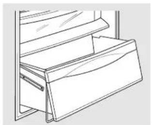
natural_image
Line drawing of a mechanical assembly with folded components (no text or symbols)natural_image
Hand pouring liquid into a container with an arrow indicating flow (no text or symbols)Prateleira de transbordamento
natural_image
Line drawing of hands opening a cabinet with an arrow indicating direction (no text or symbols)natural_image
Simple line drawing of a curved, multi-layered object with no text or symbolsnatural_image
Line drawing of a hand holding a small container with a tool, no text or symbols presentnatural_image
Line drawing of a kitchen appliance with a handle and valve (no text or symbols)natural_image
Simple line drawing of a vehicle chassis with no text or symbolsModelos 21, 23, 25, 27 e 29
ANTES DE COMEÇAR
natural_image
Technical line drawing of a mechanical assembly with no visible text or symbolsnatural_image
Mechanical assembly diagram showing a bracket with mounting holes and directional arrows (no text or labels)Parafusos de ajuste da roda
text_image
Technical diagram of a computer ventilation panel with labeled components and dimensionsnatural_image
Pure mechanical diagram showing a piston and cylinder assembly with an upward arrow, no text or symbols present.natural_image
Diagram showing a plug inserted into an electrical outlet with a magnified view of the socket (no text or symbols present)3 LIGUE O DISPENSADOR DE GELO
text_image
-18 SET 3 SET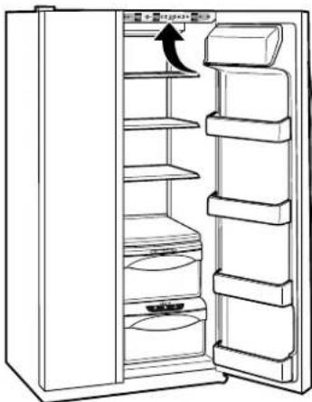
natural_image
Line drawing of an open refrigerator with shelves and a door, showing no text or symbolsnatural_image
Line drawing of an open refrigerator with shelves and doors, showing a hand pointing to the door (no text or symbols present)natural_image
Line drawing of an open refrigerator with shelves and doors, showing a right-handled door (no text or symbols)natural_image
Two technical diagrams showing a battery and a droplet with liquid, no text or symbols present.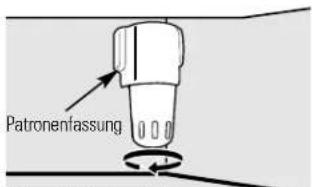
natural_image
Diagram of a refrigerator interior showing internal compartments and directional arrows indicating movement (no text or labels)natural_image
Line drawing of a mechanical device with internal grid structure (no text or symbols)Kühlschrankkippfach
natural_image
Pure diagram of a mechanical or architectural component with no visible text, numbers, or symbolsnatural_image
Abstract line drawing with black arrows pointing upward and downward on a light background (no text or symbols)natural_image
Illustration of stacked documents with a pen and arrow indicating a file or document (no text or symbols present)QuickSpace™ Regal
natural_image
Line drawing of a mechanical device with handle and wheels (no text or symbols)text_image
Diagram showing two labeled parts (① and ②) with directional arrows indicating movement or flow between them.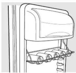
natural_image
Line drawing of a mechanical device with rollers and a top cover (no text or symbols)natural_image
Line drawing of a microwave oven mounted on a stand, with an inset showing the lid mechanism (no text or symbols)natural_image
Technical line drawing of a structural support bracket with vertical ribs and horizontal spans (no text or symbols)Gefrierfach-Körbe
natural_image
Technical line drawing of a metal rack with a black clip and vertical guide (no text or symbols)text_image
Diagram showing two labeled parts of a mechanical device with arrows indicating direction or movement.text_image
Diagram showing a structural beam under load with labeled components and directional arrowsnatural_image
Line drawing of a refrigerator with three shelves and top shelf (no text or symbols)natural_image
Simple line drawing of a sphere with two small circles and connecting arcs, no text or symbols present.natural_image
Pure technical line drawing of a mechanical component or bracket (no text or symbols)natural_image
Line drawing of a mechanical assembly with folded folders and brackets (no text or symbols)natural_image
Simple line drawing of a computer monitor with two arrows pointing to the front panel (no text or symbols)natural_image
Line drawing of hands opening a cabinet with an arrow indicating direction (no text or symbols)natural_image
Simple line drawing of a three-tiered oval-shaped object with concentric layers (no text or symbols)Abtropffach
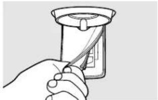
natural_image
Line drawing of a hand holding a small object with a tool, no text or symbols presentnatural_image
Line drawing of a kitchen appliance with a handle and side panel, no text or symbols presentnatural_image
Simple line drawing of a vehicle chassis with no text or symbolsGefrierfach
text_image
6 mm Maximumnatural_image
Technical line drawing of a mechanical assembly with no visible text or symbolsnatural_image
Mechanical assembly diagram showing a bracket with mounting holes and a directional arrow (no text or labels)natural_image
Technical line drawing of a computer ventilation cover with labeled dimensions (no text or symbols present)natural_image
Pure mechanical diagram showing a bolt and housing with an upward arrow, no text or symbols presentnatural_image
Diagram showing a plug inserted into an electrical outlet with a magnified view of the socket (no text or symbols)text_image
-18 SET 3 SET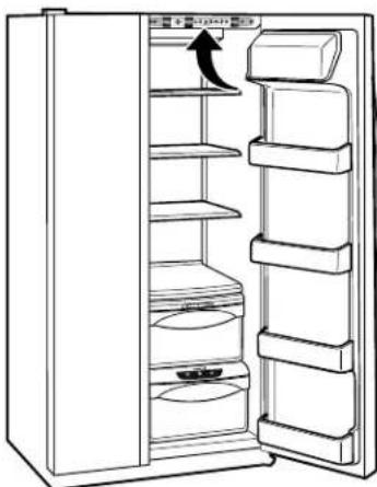
natural_image
Line drawing of an open refrigerator with shelves and a door, showing no text or symbolsnatural_image
Line drawing of an open refrigerator with shelves and doors, showing a handle and lid (no text or symbols)natural_image
Line drawing of a refrigerator with shelves and doors open, showing internal storage compartments (no text or symbols)natural_image
Line drawing of a refrigerator interior showing drawer, sink, and seat (no text or symbols)ExpressThaw™
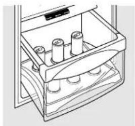
natural_image
Line drawing of a laboratory apparatus with three cylindrical components inside a drawer (no text or symbols)ExpressChill™
Gebruiksaanwijzing
natural_image
Two technical illustrations: top shows a cylindrical container with internal features, bottom shows a droplet with liquid drops (no text or symbols)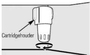
text_image
Cartridgeholdernatural_image
Technical line drawing of a refrigerator door mechanism showing internal compartments and directional arrows (no text or symbols)natural_image
Line drawing of a mechanical component with an arrow indicating direction (no text or symbols)natural_image
Technical line drawing of a mechanical component with internal grid structure (no text or symbols)natural_image
Pure technical line drawing of a mechanical component with no text or symbolsnatural_image
Abstract line drawing with two black arrows pointing upward, no text or symbols presentnatural_image
Illustration of stacked documents with a black arrow pointing to one sheet (no text or symbols present)QuickSpace™-rek
natural_image
Line drawing of a mechanical component with no visible text or symbolstext_image
Diagram showing two labeled mechanical or fluid dynamics steps with directional arrows indicating flow or movement.
natural_image
Line drawing of a mechanical device with rollers and a top cover (no text or symbols)Deur Wijnrek/Drankrek (met sommige modellen)
natural_image
Line drawing of a mailbox with ladder and support structure (no text or symbols)text_image
Verdelingnatural_image
Technical line drawing of a structural support bracket (no text or symbols)Manden in vriesvak
natural_image
Technical line drawing of a metal rack with a handle and lever mechanism (no text or symbols)Uitschuifbare rekken in vriesvak
text_image
Diagram showing two labeled components (1 and 2) of a mechanical device with arrows indicating direction or movement.Vaste rekken in vriesvak
text_image
Diagram showing a mechanical or structural assembly with labeled components and directional arrows indicating motion or force.natural_image
Line drawing of a multi-tiered storage cabinet or rack unit (no text or symbols)natural_image
Simple line drawing of a circular object with internal vertical bands and two small circular symbols on the sides (no text or labels)Transformeerbare vleeslade
natural_image
Line drawing of a mechanical component or bracket with no visible text or symbolsnatural_image
Simple line drawing of a container with arrows indicating flow or movement (no text or symbols)natural_image
Line drawing of a mechanical assembly with folded components (no text or symbols)natural_image
Line drawing of a box labeled 'IJslade' on a stand (no other text or symbols)IJslade
natural_image
Line drawing of hands opening a refrigerator with an arrow indicating direction (no text or symbols)natural_image
Simple line drawing of a curved rectangular object with three horizontal oval layers, resembling a tray or vent (no text or symbols)natural_image
Line drawing of a hand holding a small container with a handle, no text or symbols presentnatural_image
Line drawing of a kitchen appliance with arrows indicating motion (no text or symbols)natural_image
Simple line drawing of a mechanical component with no text or symbolsDiepvriesgedeelte
WATERTOEVOER NAAR DE IJSMACHINE (SOMMIGE MODELLEN)
natural_image
Technical line drawing of a mechanical assembly with no visible text or symbolsnatural_image
Mechanical assembly diagram showing a bracket with mounting holes and directional arrows (no text or labels)text_image
Technical diagram of a computer ventilation panel with labeled components and dimensionsnatural_image
Mechanical assembly diagram showing a bolt and housing with an upward arrow (no text or symbols)natural_image
Diagram showing a plug inserted into an electrical outlet with a magnified view of the socket (no text or symbols present)3 IJSMACHINE STARTEN
text_image
-18 SET 3 SET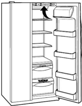
natural_image
Line drawing of an open refrigerator with shelves and a door, showing no text or symbolstext_image
Diagram showing three identical circular icons with symbols and the number '5' in black, likely representing a control or indicator panel.