
1:18 TOYOTA FJ Cruiser - Remote control toy FMS - Free user manual and instructions
Find the device manual for free 1:18 TOYOTA FJ Cruiser FMS in PDF.

| Product type | Radio-controlled toy – Miniature off-road car |
| Brand | FMS |
| Model | 1:18 TOYOTA FJ Cruiser |
| Scale | 1:18 |
| Body material | Rigid molded plastic |
| Transmitter power supply | 4 AAA 1.5V batteries (not included) |
| Vehicle power supply | LiPo 2S 7.4V 380mAh battery (included) |
| Charger | FMS USB charger (included) |
| Motor | 050 motor |
| Servo | 1 kg torque servo, 3 wires |
| Radio frequency | 2.4 GHz |
| Range | >100 m (on ground) |
| Transmitter dimensions | 152 x 75 x 167 mm |
| Transmitter weight | 160 g |
| Lighting | LED: headlights, tail lights, turn signals, reverse lights, spotlights |
| Drive modes | Normal mode, beginner mode (power limited to 50%), crawling mode (active braking on slopes) |
| Settings | Steering trim, throttle trim, steering angle (30%, 50%, 100%), steering/throttle direction reverse |
| Lighting functions | Light control via transmitter: headlights (low/high beam), turn signals, brake lights, reverse lights |
| Spare parts available | Yes: body, tires, wheels, shocks, drivetrain, electronics, etc. |
| Maintenance | Clean after use, store in a dry place, disconnect battery if not used for extended periods |
| Safety | Do not use without supervision for children under 14; follow LiPo charging instructions; check range before use |
| Certifications | CE, FCC ID: 2AUBX-HT-TX |
Frequently Asked Questions - 1:18 TOYOTA FJ Cruiser FMS
User questions about 1:18 TOYOTA FJ Cruiser FMS
0 question about this device. Answer the ones you know or ask your own.
Ask a new question about this device
Download the instructions for your Remote control toy in PDF format for free! Find your manual 1:18 TOYOTA FJ Cruiser - FMS and take your electronic device back in hand. On this page are published all the documents necessary for the use of your device. 1:18 TOYOTA FJ Cruiser by FMS.
USER MANUAL 1:18 TOYOTA FJ Cruiser FMS
The all-new FMS 1:18 Cruiser perfectly captures essence of the original design of Land Cruiser design while boldly evolved to a new style of "Be Pioneer, Go Adventure" style.
FMS 1:18 Cruiser, as an officially licensed detailed scale replica, also represents a strengthened off-road vehicle with splendid realistic details, from widened wheel-brows on both sides, right waders, to heavy-duty front wading bumper; from hard-shell body with classic yellow and white paint scheme, full-scale interior cockpit, center console and seats, to the scale luggage rack and three front wipers, footrests, etc.
Cruiser, as FMS always did, demonstrated impressed LED lighting function by adopting the most detailed features with all transparent lights equipped and scale linkage-function light controls delicately embodied, including headlights, turn signals and reverse lights. Barely no other cars can compete with Cruiser in reserving light controls for search lights on the bumper, the fog lights on both sides and the turn signals on the rearview mirror.
A feature-packed trail-proven chassis drives the Cruiser. Aluminum rails provide a rigid platform while a multilink geometry with panhard bar chassis design allows for maximum axle articulation. Power is delivered from the super high-torque gearbox to ultra grippy beadlock tires via nylon driveshafts. We are proud to announce that Cruiser's wheels can match all tires of the same scale, making it easy for players to DIY.
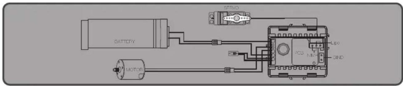
Power-packed electronics consists of independent servo, 2-in-1 receiver/ESC, 050 motor and 7.4V 380mAh battery; Allowing for high power-to-weight ratio and all weather operations.
FMS 1:18 Cruiser, see the difference and bring it home.
Transmitter intruction
![[1] [2] [3] [4] [5] [6] [7] [8] [9] E,Reset REV/ST A/B Mode ST TRIM TH TRIM CHS/Climbing CHA/Train CHG ON/OFF](/content/2026/04/693287/images/5515266bfccec1522621ef53befa9626ec69a09f85a5415b1b3e3e4de94d13ea.jpg)
![[10] [11]](/content/2026/04/693287/images/12dbb9c79933c0b904d9f7318ed9074815b90efbd93e46c922edda865e0e88f0.jpg)
| [1] | A/B Mode switch key | [7] | Throttle trim + (TH TRIM +) mode A / light control switch 1 mode B |
| [2] | Re-set button (F.Reset) Mode A | [8] | Throttle trim – (TH TRIM –) mode A / light control switch 2 mode B |
| [3] | Steering Trim+ (ST TRIM+) Mode A | [9] | Channel 6 (reserved) |
| [4] | Steering Trim- (ST TRIM-) Mode A | [10] | Steering wheel |
| [5] | Power Switch | [11] | Throttle trigger |
| [6] |
Reverse key mode a
/ steering angle limit mode B
| A/B mode function toggle switch | ||
| F.Reset | In the use of the disorder settings, not back to the normal state, you can use Factory.Reset function | Make sure that the mode function toggle switch is in mode A, hold the steering wheel left or right, and click the F. Reset button at the same time. After two clicks, it means that the factory settings have been completed. |
| REV | After replacing the steering gear, the steering gear is reversed | Make sure that the mode function toggle switch is in mode A, twist the left or right steering wheel, and click Rev button at the same time. After ringing, it means that the reverse setting of steering gear has been completed. |
| After replacing the motor, there is a reverse | Make sure that the mode function toggle switch is in mode A, pull or push the throttle, and click Rev button at the same time. After ringing, it means that the motor reverse setting has been completed. | |
| Adjust 30 / 50 / 100% steering radian | Make sure that the mode function toggle switch is in mode B, and click the ST Angle key. After a click, it means that the 30% steering radian has been set. Click the ST Angle button again, and you will hear two beeps, indicating that the setting of 50% steering radian has been completed. Click the ST Angle button again, and you will hear three beeps, indicating that the 100% steering radian has been set. Then click to cycle to a click to indicate that the 30% steering radian has been set. | |
| ST TRIM | When the steering center is not centered | Make sure that the mode function toggle switch is in mode A, press ST TRIM+ or - button to fine tune the steering center. Every click of the button will ring. When the maximum and minimum values are reached, a long sound will appear. When the median value is reached, it will ring twice. |
| TH TRIM | When the throttle is not centered | Make sure that the mode function toggle switch is in mode A, press TH TRIM + / - button to fine tune the throttle center. Every click of the button will ring. When reaching the maximum and minimum value, the button will ring, when reaching the median value, the button ring twice. |
| LED | Light setting | Make sure that the mode function toggle switch is in mode B, click the LED button, and the headlamp will be on after a click. Then click the LED button, and the headlight will be highlighted after two clicks. Continue to click the LED button, and the air defense light will be on after three rings. |
| Emitter: forget reminder | If the transmitter does not receive any command, it will give an alarm after 10 minutes and enter sleep mode after 2 minutes |
| Transmitter: frequency alert | When the transmitter does not match the receiver, the indicator light of the transmitter keeps flashing |
| Transmitter: no frequency matching + low power reminder 4.5V | The indicator light of the transmitter flashes slowly and makes a sound |
| Transmitter: low power reminder 4.5V | The indicator light of the transmitter flashes slowly |
| Car: frequency alert | The headlights keep flashing |
| Car: low power alarm 6.3–6.4v | All lights keep flashing, steering and throttle are not controlled |
| Car: reminders to prevent forgetting | If the vehicle does not receive any signal, it will flash back and forth after 10 minutes and enter sleep mode after 2 minutes |
| Times for Pressing | |||||||||||
| Button | Light Position | Function | Power on is off by default | I II | III IV | V | Control Mod | Remarks | |||
| LED1# | Headlight | Always on | • | OFF | OFF | OFF | OFF | ||||
| Always Off | OFF | • | • | OFF | OFF | ||||||
| Taillights | Always on | • | • • | OFF | OFF | ||||||
| Reversing light | ○ | ○ | ○ | OFF | OFF | Throttle linkage control | The light is on when reversing | ||||
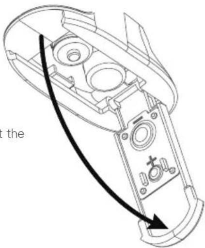
Transmitter Battery Installation
Battery Type: AAA
Battery Installation:
- Open the battery compartment cover.
-
Insert 4 fully-charged AAA batteries into the compartment. Make sure that the battery makes good contact with the battery compartment's contacts.
-
Replace battery compartment cover.
Low battery alarm: When the battery is lower than 4.2V, the LED on the panel will flash slowly.
Note: When installing the batteries, be careful to handle the positive and negative poles. (As shown in the picture on the right)
Warnings
- This vehicle is not intended for those under 14 years of age without proper adult supervision. It is not a toy!Failure to operate or maintain this vehicle in a safe manner can result in bodily harm.
- Replace damaged components with original factory-parts. Pay special attention to the polarity of all vehicle wiring.
- Only use approved 2 cell lithium polymer batteries. Do not over-charge or over dis-charge the battery as doing so may cause the battery to become a fire hazard. If the battery should become hot during charging, discontinue charging immediately and disconnect the battery from the charger. Never leave the battery unattended while charging. If you are unsure of how to charge this battery, please seek the advice of experienced RC users. Never let children charge the battery without adult supervision.
- The motor will become hot during use. Allow 10–15 minutes between runs for the vehicle to cool down. Doing so will prolong the life of your vehicle.
- Use common sense when selecting the environment to operate your vehicle. Do not operate near power cables, cellular/radio towers, deep water or unstable terrain. The operator is solely responsible for their actions.
- The product is composed of precision electrical components. It is critical to keep the product away from moisture and other contaminants. If exposed to a humid environment, make sure the electronics are fully dried prior to using them again.
- Always check the radio range of the vehicle prior to operation in order to prevent radio loss or interference.
- Operate this product within your ability. If the vehicle is dangerous to retrieve, it's never worth the risk.
- Always turn on the transmitter before connecting the battery on the model. When turning off the model, always disconnect the battery first, and then turn off the model, always disconnect the battery first, and then turn off the transmitter. If this order is reversed, the model may become uncontrollable and cause serious damage.
- Never allow transmitter batteries to run low as it may cause loss of vehicle control.
- Plastics on the vehicle are susceptible to damage or deformation due to extreme heat and cold climate. Do not store the model near any source of heat such as oven or heater. Store the model indoors, in a climate-controlled, room temperature environment.
- Never shorten the receiver antenna; this may affect the transmitting range of the radio system.
- Only use specified battery (X4 AAA batteries).
- Do not open, disassemble, or attempt to repair the battery.
- Do not crush/puncture the battery, or short the external contacts.
- Do not expose to excessive heat or liquids.
- Do not drop the battery or expose to strong shocks or vibrations.
• Always store the battery in a cool, dry place.
- Do not use the battery if damaged.
• The Battey must be disconnected the receiver when charging.
Power On
Follow the steps below to turn on the transmitter:
-
Check to make sure that that battery is fully charged and installed correctly.
-
Toggle the switch to the [ON] position. When active the R.LED will be lit.
-
Connect the receiver to power.
- For safety always power on the transmitter before the receiver.

Note
- Operate with caution in order to avoid damage or injury.
• Make sure that the throttle is at its lowest position and the switches are set to their up position.
Instructions
After setting up, follow the instructions below to operate the system.
- Automatic code matching (the transmitter and receiver have been successfully coded before leaving the factory.)
If you need to replace another transmitter or receiver, please follow the following steps to code:
- When the transmitter power is on and the code matching mode is on, the light keeps flashing;
- The power supply of the receiving board is turned on, and the front lights keep flashing to enter the code matching mode;
- When the code matching is successful, all the transmitter lights are on and all the lights on the car are off;
Note: when code matching, please operate the transmitter to enter the code matching state first, and then operate the receiver to enter the code matching state.
2、POWER OFF
Follow the steps below to turn off the system:
- Disconnect the receiver power.
- Toggle the transmitter's power switch to the off position.

Note
Make sure to disconnect the receiver power before turning off the transmitter. Failureto do so may lead to damage or serious injury.
Motordaten
| Product Model | HT-TX02 |
| Adaptive model | Car |
| RF | 2.4GHz |
| Transmitting power | <20dBm |
| Wireless protocol | ANT |
| Distance | >100m(ground) |
| Channel Resolution | 256 Grade |
| Battery | 6V DC 1.5AAA*4 |
| Charging Interface | NO |
| Life time | According to battery type |
| Low Voltage Warning | <4.45V |
| Antenna Type | Built-in single antenna |
| Data interface | NO |
| Temperature Range | -10°C ~ +60°C |
| Humidity Range | 20–95% |
| Online Update | NO |
| Color | Black |
| Size | 152mm *75mm *167mm |
| Weight | 160g |
| Certification | CE, FCC ID: 2AUBX-HT-TX02 |
Throttle stick position
Top point of backward direction Top point of

natural_image
Abstract geometric shape resembling a stylized letter or symbol (no text or symbols present)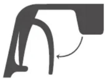
natural_image
Abstract diagram of a curved mechanical or architectural component with an arrow indicating rotation (no text or symbols)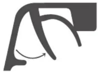
natural_image
Abstract curved line drawing with a curved arrow, no text or symbols presentOperating the vehicle
Step 1: turn on the transmitter, the headlamp of the transmitter will flash and enter the frequency matching mode.
Step 2: turn on the receiver switch, the headlight will flash and enter the frequency matching mode.
Step 3: when the transmitter and receiver are successful in frequency up, the front lights of the transmitter will be on for a long time, and the front lights of the vehicle will be off.
Setting the Gear Mesh
The gear mesh is the clearance between the pinion and spur gears in your vehicle. If the motor or gearing components are replaced, check that the gears are not meshing too tightly as this may cause premature wear.

natural_image
Abstract gear and chain icon illustration (no text or symbols)Charging the Battery
- Connect the charger to a USB port then connect the battery to the charger.
- When charging, the Green LED is flash, when charged, the Green LED is stable.
3.Do not let the battery charge unattended! - If the battery or charger is hot, disconnect the battery and charger immediately as this may be caused by an internal short-circuit.
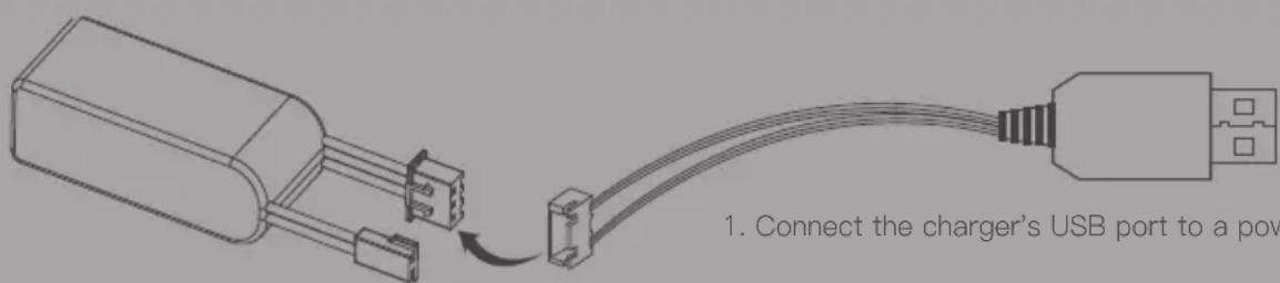
- Connect the battery to the charger.
EN
• Always charge LiPo batteries on non-flammable, heat-resistant surfaces.
- Always use a LiPo-safe bag or container while charging. Do not allow LiPo cells to overheat at any time. Cells which reach greater than 140 Fahrenheit(60°C) will usually become damaged and will catch fire.
- Do not charge the LiPo pack while it is still in the model. Never charge or store battery packs in a vehicle.
- Do not discharge LiPo; doing so will damage the battery.
- Do not expose LiPo cell to water or moisture at any time.
- Do not store battery near open flame or heater.
- Do not assemble LiPo cells or pre-assembled packs together with other LiPo cells or packs.
• Always store LiPo battery in a secure location away from children.
• Always remove the LiPo battery if model is involved in any kind of crash.
- Carefully inspect the battery and connectors for even the smallest damage.
- CAUTION:Cells may become hot after usage.Allow the pack to cool to room temperature prior to recharging.
- Do not allow the electrolyte to get into eyes or on skin. Wash affected areas immediately if they if they come into contact with electrolyte. Do not alter or modify connectors or wires of a LiPo battery pack.
• Always inspect the condition of the battery before charging and operating.
- Do not short circuit the LiPo battery.
- Do not have contact with a leaky/damaged battery directly.
- Do not charge battery out of recommended temperature range(O°C 45°C).
natural_image
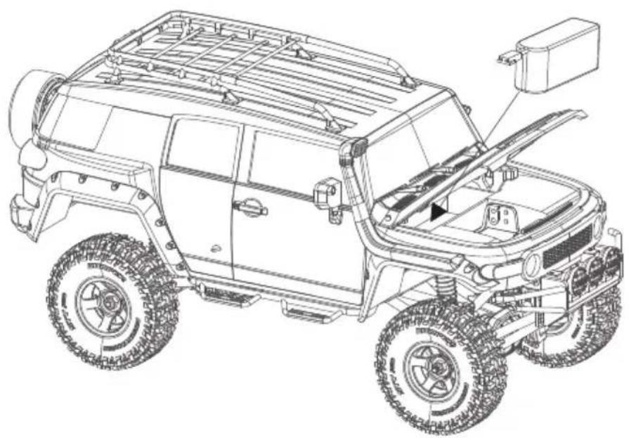
Technical line drawing of a vehicle's front view showing engine, chassis, and dashboard components (no text or labels)
NOTE
- If it is not in use for a long time, unplug and take off the battery to prevent battery leakage
- Do not open, disassemble, or attempt to repair the battery.
Spare parts list
| C2092 | 1:18 FJ Cruiser Hood YELLOW |
| C2093 | 1:18 FJ Cruiser Front and Rear Light Cup Set |
| C2094 | 1:18 FJ Cruiser Hood Mount Set |
| C2095 | 1:18 FJ Cruiser Ladder And Spare Tire Bracket |
| C2096 | 1:18 FJ Cruiser Spotlight Cup Set |
| C2097 | 1:18 FJ Cruiser Rearview Mirror And Wiper |
| C2098 | 1:18 FJ Cruiser Bumper And Side Panel |
| C2099 | 1:18 FJ Cruiser Lens |
| C2100 | 1:18 FJ Cruiser Body SHELL YELLOW |
| C2101 | 1:18 FJ Cruiser Car Roof |
| C2045 | Teraz Tire 19.2 x 13.5 x 56 |
| C2046 | 1:18 Star Style Wheels plastic parts |
| C2052 | FMS LIPO Battery 2S LIPO 380mAh |
| C2051 | FMS USB Charger |
| C2049 | 1:18 050 Motor set |
| C2057 | 1:18 Plastic Gear set |
| C2058 | 1:18 Transmission Shaft full set |
| C2102 | 1:18 SCREW SET |
| C2021 | 1:18 1KG High Torque 3wire Servo |
| C2103 | 1:18 FJ Cruiser Window |
| C2074 | 1:18 Rear Wheel Shaft |
| C2071 | 1:18 Wheel Hex |
| C2063 | 1:18 SHOCK PLASTIC PARTS |
| C2064 | 1:18 KATANA V2 / LC80 LAND CRUISER/ FJ Cruiser Connecting Rod |
| C2065 | 1:18 M4 ALLY BALL |
| C2066 | 1:18 BALL HEAD |
| C2067 | 1:18 Steering Hub & Spindle |
| C2068 | 1:18 FRONT/REAR AXLE parts |
| C2069 | 1:18 SERVO HORN |
| C2104 | 1:18 FJ Cruiser MIRROR LENS |
| C2075 | 1:18 FRONT OUTDRIVE SHAFT |
| C2076 | 1:18 Gear Box Plastic Parts |
| C2105 | 1:18 FJ Cruiser dash board SET |
| C2106 | 1:18 FJ Cruiser dash board seat SET |
CE Warning
The antenna(s) used for this transmitter must be installed to provide a separation distance of at least 20 cm from all persons and must not be co-located or operating in conjunction with any other transmitter. End-users and installers must be provided with antenna installation instructions and transmitter operating conditions for satisfying RF exposure compliance.
Appendix 1 FCC Statement
FCC ID: 2AUBX-HT-TX02
This equipment has been tested and found to comply with the limits for a Class B digital device pursuant to part 15 of the FCC rules. These limits are designed to provide reasonable protection against harmful interference in a residential installation. This equipment generates, uses and can radiate radio frequency energy and, if not installed and used in accordance with the instructions, may cause harmful interference to radio communications. However, there is no guarantee that interference will not occur in a particular installation. If this equipment does cause harmful interference to radio or television reception, which can be determined by turning the equipment off and on, the user is encouraged to try to correct the interference by one or more of the following measures:
- Reorient or relocate the receiving antenna.
- Increase the separation between the equipment and receiver.
- Connect the equipment into an outlet on a circuit different from that to which the receiver is connected.
- Consult the dealer or an experienced radio/TV technician for help.
To assure continued compliance, any changes or modifications not expressly approved by the party responsible for compliance could void the user's authority to operate this equipment.
This equipment complies with Part 15 of the FCC Rules. Operation is subject to the following two conditions:
(1) This device may not cause harmful interference.
(2) This device must accept any interference received, including interference that may cause undesired operation.
Caution!
The manufacturer is not responsible for any radio or TV interference caused by unauthorized modifications to this equipment. Such modifications could void the user authority to operate the equipment.
- The antenna(s) used for this transmitter must be installed to provide a separation distance of at least 20 cm from all persons and must not be co-lacated or operating in conjunction with any other transmitter.End-users and installers must be provided with antenna installation instructions and transmitter operating conditions for satisfying RF exposure compliance.
- Move all your channels to the desired position.
- Select [All channels] and then [Yes] in the confirmation box.
Declaration of Conformity (DoC)
We,
Dongguan Solid Model Technology Co., Ltd
3/F, Building B, 3rd Industry Zone,
Matigang, Dalingshan Town
Dongguan City of China 523810.
Phone:0769-86976655
Web:www.fmsmodel.com
declare under our responsibility that the product:
Type of Equipment: Driving System & 2.4GHz Control System
Brand Name: FMS
Compatible for cars: 1:18 FJ CRUISER
Equipment Model: 11806

to which this declaration relates is in conformity with the essential requirements and other relevant requirements of the Directive 2014/53/EU, EMC Directive 2014/30/EU, EMC Directive 2014/53/EU, FCC Indentifier 2AUBX-HT-TX02, EU RoHS Directive 2011/65/EU and Council Directive 2014/30/EU. The product is in conformity with following standards and/or other normative documents:
ETSI EN 301 489-1 V2.2.3(2019-11)
ETSI EN 301 489-17 V3.2.4(2020-09)
EN 55032:2015+A11:2020
EN 55035:2017+A11:2020
EN61000-3-2:2014
EN61000-3-3:2013
EN:62479:2010
ETSI EN 300 328 V2.2.2 (2019–07)
DISTRIBUTOR
North America:
AMain Distributing
424 Otterson Drive
Chico, CA 95928
https://www.amaindistributing.com/
530-894-9082
Sweden:
Minicars Hobby Distribution AB
Annelundsgatan 17C
749 40 Enköping, Sweden
Tel.: +46-171-14 30 02
The United Kingdom:
CML Distribution Ltd
Saxon House, Saxon Business Park, Hanbury Road
Bromsgrove, Worcestershire
B60 4AD, England
Tel.: +44 (0)1527 575349
Australia:
Model Engines Pty Ltd
Unit 1/32 Bluett Drive
Smeaton Grange
NSW 2567 Australia
Transmitter intruction
![[1] [2] [3] [4] [5] [6] [7] [8] [9] E.Reset A/B Mode ST TRIM TH TRIM CHS/Climbing CHA/Train CHG ON/OFF](/content/2026/04/693287/images/dc2eb9ebb874626c00c730b02280a4f1ed21569c99d5fe20c829eb045e15f818.jpg)
![[10] [11]](/content/2026/04/693287/images/180c08fd155b2b732233ebbf33b38a3d1b421a0de1226d4e6a55d5239dfa1f92.jpg)
| [1] | A/B Modus–Schalttaste | [7] | Drosseltrimmung + (TH TRIM +) Modus A / Lichtschalter 1 Modus B |
| [2] | Reset–Taste (F.Reset) Modus A | [8] | Drosseltrimmung + (TH TRIM +) Modus A / Lichtschalter 2 Modus B |
| [3] | Lenkung Trim+ (ST TRIM+) Modus A | [9] | Kanal 6 (belegt) |
| [4] | Lenkung Trim- (ST TRIM-) Modus A | [10] | Steering wheel |
| [5] | Power Switch | [11] | Throttle trigger |
| [6] |
Reverse key mode a
/ steering angle limit mode B
natural_image
Technical line drawing of a device casing with internal components and a curved arrow indicating direction (no text or symbols)Warnhinweise
• Always store the battery in a cool, dry place.
Transmitter specification
| Product Model | HT-TX02 |
| Adaptive model | Car |
| RF | 2.4GHz |
| Transmitting power | <20dBm |
| Wireless protocol | ANT |
| Distance | >100m(ground) |
| Channel Resolution | 256 Grade |
| Battery | 6V DC 1.5AAA*4 |
| Charging Interface | NO |
| Life time | According to battery type |
| Low Voltage Warning | <4.45V |
| Antenna Type | Built-in single antenna |
| Data interface | NO |
| Temperature Range | -10°C ~ +60°C |
| Humidity Range | 20–95% |
| Online Update | NO |
| Color | Black |
| Size | 152mm *75mm *167mm |
| Weight | 160g |
| Certification | CE, FCC ID: 2AUBX-HT-TX02 |
Gasstellung
natural_image
Abstract geometric shape resembling a stylized letter or symbol (no text or symbols present)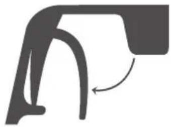
natural_image
Abstract diagram of a curved mechanical or architectural component with an arrow indicating rotation (no text or symbols)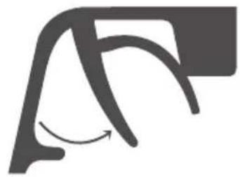
natural_image
Abstract curved line drawing with a curved arrow, no text or symbols presentSetting the Gear Mesh
natural_image
Gray gear icon with a diagonal line, no text or symbols presentLaden des Akkus
natural_image
Technical line drawing of a UMV-style off-road vehicle showing front wheel, rear window, and engine compartment (no text or symbols)
Dongguan Solid Model Technology Co., Ltd
3/F, Building B, 3rd Industry Zone,
Matigang, Dalingshan Town
Dongguan City of China 523810.
Phone:0769-86976655
Web:www.fmsmodel.com
ETSI EN 300 328 V2.2.2 (2019–07)
DISTRIBUTOR
North America:
AMain Distributing
424 Otterson Drive
Chico, CA 95928
https://www.amaindistributing.com/
530-894-9082
Sweden:
Minicars Hobby Distribution AB
Annelundsgatan 17C
749 40 Enköping, Sweden
Tel.: +46-171-14 30 02
The United Kingdom:
CML Distribution Ltd
Saxon House, Saxon Business Park, Hanbury Road
Bromsgrove, Worcestershire
B60 4AD, England
Tel.: +44 (0)1527 575349
Australia:
Model Engines Pty Ltd
Unit 1/32 Bluett Drive
Smeaton Grange
NSW 2567 Australia
natural_image
Technical line drawing of a handheld device with a curved arrow indicating direction (no text or symbols)Avertissements
natural_image
Abstract geometric shape resembling a stylized letter or symbol (no text or symbols present)
natural_image
Abstract diagram of a curved mechanical or architectural component with an arrow indicating rotation (no text or symbols)
natural_image
Abstract curved line drawing with a curved arrow, no text or symbols presentnatural_image
Abstract gear and gear icon illustration (no text or symbols)natural_image
Technical line drawing of a vehicle's front view showing engine, chassis, and dashboard components (no text or labels)
NOTE
Dongguan Solid Model Technology Co., Ltd
3/F, Building B, 3rd Industry Zone,
Matigang, Dalingshan Town
Dongguan City of China 523810.
Phone:0769-86976655
Web:www.fmsmodel.com
Equipment Model: 11806

ETSI EN 300 328 V2.2.2 (2019–07)
DISTRIBUTOR
North America:
AMain Distributing
424 Otterson Drive
Chico, CA 95928
https://www.amaindistributing.com/
530-894-9082
Sweden:
Minicars Hobby Distribution AB
Annelundsgatan 17C
749 40 Enköping, Sweden
Tel.: +46-171-14 30 02
The United Kingdom:
CML Distribution Ltd
Saxon House, Saxon Business Park, Hanbury Road
Bromsgrove, Worcestershire
B60 4AD, England
Tel.: +44 (0)1527 575349
Australia:
Model Engines Pty Ltd
Unit 1/32 Bluett Drive
Smeaton Grange
NSW 2567 Australia
![[12] [13] [14]](/content/2026/04/693287/images/a7a7ac50b3cff148701bb84c9c910e5c3a685f47516bf699f3a6c2ee8b053545.jpg)
natural_image
Technical line drawing of a handheld device with a curved arrow indicating direction (no text or symbols)警告
natural_image
Three abstract curved line patterns with arrow indicators, no text or symbols present车辆操作
natural_image
Abstract gear icon with interlocking teeth, no text or symbols present电池充电
natural_image
Technical line drawing of a small off-road vehicle with visible engine, dashboard, and roof structure (no text or symbols)
警告
- Transmitter intruction
- Transmitter Battery Installation
- Warnings
- Power On
- Note
- Instructions
- 2、POWER OFF
- Throttle stick position
- Operating the vehicle
- Setting the Gear Mesh
- Charging the Battery
- EN
- Spare parts list
- CE Warning
- Appendix 1 FCC Statement
- FCC ID: 2AUBX-HT-TX02
- Caution!
- Declaration of Conformity (DoC)
- DISTRIBUTOR
- AMain Distributing
- Minicars Hobby Distribution AB
- CML Distribution Ltd
- Model Engines Pty Ltd
- Warnhinweise
- Gasstellung
- Laden des Akkus
- Avertissements
- 警告
- 车辆操作
- 电池充电
Brand : FMS
Model : 1:18 TOYOTA FJ Cruiser
Category : Remote control toy