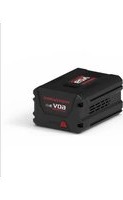
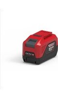
USER MANUAL P60B3 Powerworks
English (Original Instructions)
BATTERY
SPECIFICATIONS
2900413
Battery: 54V =2.0Ah, 108Wh, 60V MAX
Voltage per cell: 3.6V ; Number of cells: 15
Charge time: 60 min. (use 2900313 Charger)
Charge time: 30 min. (use 2904813 Charger)
2900913
Battery: 54V =2.5Ah, 135Wh, 60V MAX
Voltage per cell: 3.6V ; Number of cells: 15
Charge time: 75 min. (use 2900313 Charger)
Charge time: 37.5 min. (use 2904813 Charger)
2904613
Battery: 54V =3.0Ah, 162Wh, 60V MAX
Voltage per cell: 3.6V ; Number of cells: 15
Charge time: 90 min. (use 2900313 Charger)
Charge time: 45 min. (use 2904813 Charger)
2900513
Battery: 54V = 4.0Ah, 216Wh, 60V MAX
Voltage per cell: 3.6V ; Number of cells: 30
Charge time: 120 min. (use 2900313 Charger)
Charge time: 60 min. (use 2904813 Charger)
2904713
Battery: 54V =6.0Ah, 324Wh, 60V MAX
Voltage per cell: 3.6V ; Number of cells: 30
Charge time: 180 min. (use 2900313 Charger)
Charge time: 90 min. (use 2904813 Charger)
For the proper use, maintenance and storage of this battery, it is crucially important that you read and understand the instructions given in this manual.
To avoid serious injury, risk of fire, explosion and danger of electric shock or electrocution:
■ If the battery pack case is cracked or damaged, DO NOT insert into the charger. Replace with a new battery pack.
■ DO NOT charge these battery packs with
any other type of charger.
■ DO NOT try to short circuit any terminals of battery pack.
WARNING
If the battery fluid gets in your eyes, rinse immediately with clean water for at least 15 minutes. Get immediate medical attention. Do not charge the battery pack in rain or in wet conditions. Do not immerse the tool, battery pack, or charger in water or other liquid.
■ Do not allow the battery pack or charger to overheat. If they are warm, allow them to cool down. Recharge only at room temperature.
■ Do not place the battery pack in the sun or in a warm environment. Keep at normal room temperature.
- Keep in shady, cool and dry condition, if the battery is not charged for a long time; charge the battery for 2 hours every 2 months.
■ The battery pack cells may develop a small leak under extreme usage or temperature conditions. If the outer seal is broken and the leakage gets on your skin:
- Use soap and water to wash immediately.
- Neutralize with lemon juice, vinegar, or other mild acid.
■ If leakage gets in your eyes, follow instructions above and seek medical attention.
■ Please check prior use, if output voltage and current of the battery charger is suitable for the charging battery pack.
CHECKING BATTERY CAPACITY
Press the battery capacity indicator (BCI) button. The lights will illuminate according to the batteries capacity level. See chart below:
English (Original Instructions)
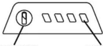
natural_image
Simple diagram of a device with four square buttons and a circular button, no text or symbols present
BATTERY CAPACITY
INDICATOR (BCI) BUTTON
| Lights | Capacity |
| 4 Green Lights he | Battery is above 80% capacity |
| 3 Green Lights he | Battery is between 80% and 60% capacity |
| 2 Green Lights he | Battery is between 60% and 40% capacity |
| 1 Green Light The | battery is between 40% and 20% capacity |
| Lights go out | The battery is less than 20% capacity and requires charging immediately |
SAFETY NOTES AND PRECAUTIONS
- Do not disassemble the battery.
- Keep away from the children.
- Do not expose the battery to water or salt water, battery should be stored in a cool and dry location and should place the battery in cool and dry environment.
- Do not place the battery in high-temperature locations, such as near a fire, heater, etc.
- Do not reverse the positive terminal and the negative terminal of the battery.
- Do not connect the positive terminal and the negative terminal of the battery to each other with any metal objects.
- Do not knock, strike or step on the battery.
- Do not solder directly onto the battery and pierce the battery with nails or other edge tools.
- In the event that the battery leaks and the fluid gets into one's eye, do not rub the eye. Rinse well with water. Immediately discontinue use of the battery, if, while using the battery emits an unusual smell, feels hot, changes color, changes shape, or appears abnormal in any other way.
BATTERY CHARGER
SPECIFICATIONS
60V Charger: 2900313
Input: 220-240V \~50/60Hz 1A
Output: 60V=2A
60V Charger: 2904813
Input: 220-240V \~50/60Hz 2A
Output: 60V=4A
■ DO NOT probe the charger with conductive materials.
■ DO NOT allow liquid inside the charger.
■ DO NOT try to use the charger for any other purpose than what is presented in this manual.
■ Unplug the charger before cleaning and when there is no battery pack in the charger.
■ Do not try to connect two chargers together.
■ Do not use the charger in the circumstances that the output Polarity does not match the load polarity.
■ For indoor use only.
■ The cover may under no circumstances be opened. If the cover is damaged, then the charger may no longer be used.
■ Do not recharge non-rechargeable batteries.
WARNING
To avoid risk of fire, electric shock, or electrocution:
- Do not use a damp cloth or detergent on the battery or battery charger.
- Always remove the battery pack before cleaning, inspecting, or performing any maintenance on the tool.
CLEANING
Wipe the outside of the charger with a dry, soft cloth. Do not hose down or wash with water.
 | Class II |
 | For indoor use only |
English (Original Instructions)
 | Before charging, read the instructions |
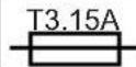 | Fuse (2900313) |
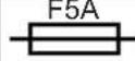 | Fuse (2904813) |
WARNING
This appliance can be used by children aged from 8 years and above and persons with reduced physical, sensory or mental capabilities or lack of experience and knowledge if they have been given supervision or instruction concerning use of the appliance in a safe way and understand the hazards involved.
- Children shall not play with the appliance.
- Cleaning and user maintenance should not be made by children without supervision.
- If the supply cord is damaged, it must be replaced by manufacturer, its service agent or similarly qualified persons in order to aviod a hazard.
- Do not cover the ventilation slots on the top of the charger. Do not set the charger on a soft surface i.e. blanket, pillow. Keep the ventilation slots of the charger clear.
- Do not allow small metal items or material such as steel wool, aluminum foil, or other foreign particles into the charger cavity.
- Use only 2900413/2900913/2904613/2900513/2904713 rechargeable Li-ion batteries.
ENVIRONMENTALLY SAFE BATTERY DISPOSAL

WARNING
All toxic materials must be disposed of in a specified manner to prevent contamination of the environment. Before disposing of damaged or worn out Lithium-ion battery packs, contact your local waste disposal agency, or the local Environmental Protection Agency for information and specific instructions. Take the batteries to a local recycling and/or disposal centre, certified for Li-ion disposal.
WARNING
If the battery pack cracks or breaks, with or without leaks, do not recharge it and do not use. Dispose of it and replace with a new battery pack. DO NOT ATTEMPT TO REPAIR IT!
To avoid injury and risk of fire, explosion, or electric shock, and to avoid damage to the environment:
- Cover the battery's terminals with heavy-duty adhesive tape.
- DO NOT attempt to remove or destroy any of the battery pack components.
- DO NOT attempt to open the battery pack.
WARNING
- If a leak develops, the released electrolytes are corrosive and toxic. DO NOT get the solution in the eyes or on skin, and do not swallow it.
- DO NOT place these batteries in your regular household trash.
- DO NOT incinerate.
- DO NOT place them where they will become part of any waste landfill or municipal solid waste stream.
- Take them to a certified recycling or disposal centre.
CHARGING PROCEDURE
NOTE: The battery is not shipped fully charged. It is recommended to fully charge before use to ensure that maximum run time can be achieved. This lithium-ion battery will not develop a memory and may be charged at any time.
2900313
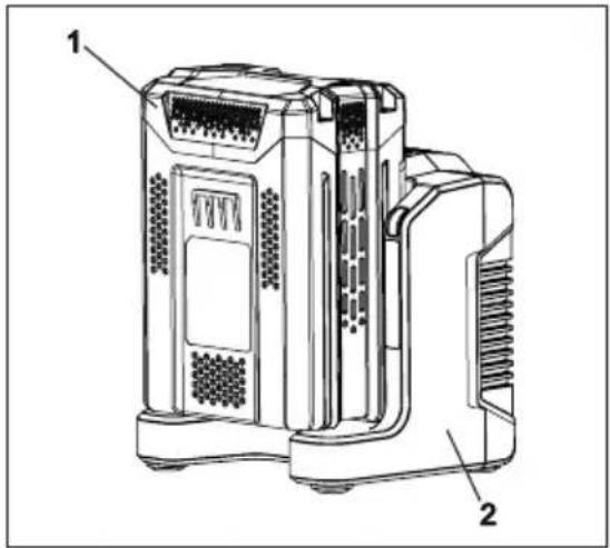
- Plug the charger into an AC power outlet.
- Insert the battery pack (1) into the charger (2).
1
2
3
1
3
This is a diagnostic charger. The Charger LED Light (3) will illuminate in specific order to communicate the current battery status. They are as follows:
2
Blinking Green Charging
Solid Green Fully Charged
Solid Red
Over Temperature
Blinking Red
Charging Fault
2904813
- Charge one battery:
-Plug the charger (1) into an AC power outlet.
-Insert the battery pack (2) into the charger (1).
- Charger two batteries:
-Plug the charger (1) into an AC power outlet.
-Insert two battery packs (2) into the charger (1).
Note: When charging two battery packs, the two batteries are charged separately. The charger will charge one battery first. After one battery is fully charged, it will charge the other battery.
False Defect Note:
When the battery is inserted into the charger, and the status LED flashes, remove the battery from the charger for 1 minute, then reinsert. If the status LED indicates normal than the battery pack is good. If the status LED is still blinking, remove the battery pack and unplug the charger. Wait 1 minute and plug the charger back in and reinsert the battery pack. If the status LED indicates normal than the battery pack is good. If the status LED is still blinking then the battery pack is defective and needs to be replaced.
NOTE: When the red indicator flickers, pull out the battery from the charger and insert again within 2 hours. If the indicator shows charging, that means the battery is good. After 2 hours, please pull out the battery and also pull out the AC power plug of the charger for 1 minute, and then insert the AC power plug and the battery again. If the indicator shows
English (Original Instructions)
charging, that means the battery is good. If not, the battery needs to be changed.
CHECKING THE CHARGER
If the battery pack does not charge properly:
- Check the current at the power outlet with another tool. Make sure that the outlet is not turned off.
- Check that the charger contacts have not been shorted by debris or foreign material.
- If the surrounding air temperature is not normal room temperature, move the charger and battery pack to a location where the temperature is between 7 °C and 40°C.
WARNING
If the battery is inserted into the charger when warm or hot, the CHARGING LED indicator light on the charger may switch on and illuminate RED. If this occurs allow the battery to cool outside of the charger for approximately 30 minutes.
CHARGER MOUNTING
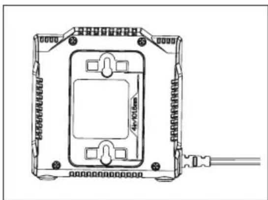
- This charger can be installed hanging on a wall using two #8 screws (not supplied).
- Locate the placement for the charger to be wall mounted.
- If fastening to wood studs use 2 wood screws (not included).
- Drill two holes on center 101.6mm apart ensuring that they are vertically aligned.
- If fastening to drywall use wall anchors (not included) and screws to secure the charger to the wall.
natural_image
Technical line drawing of a rectangular electronic device with mounting holes and internal components, no text or symbols present.
NOTE: If the battery and the charger won't be used for a long time, please remove the
battery from the charger and pull out the AC power plug.
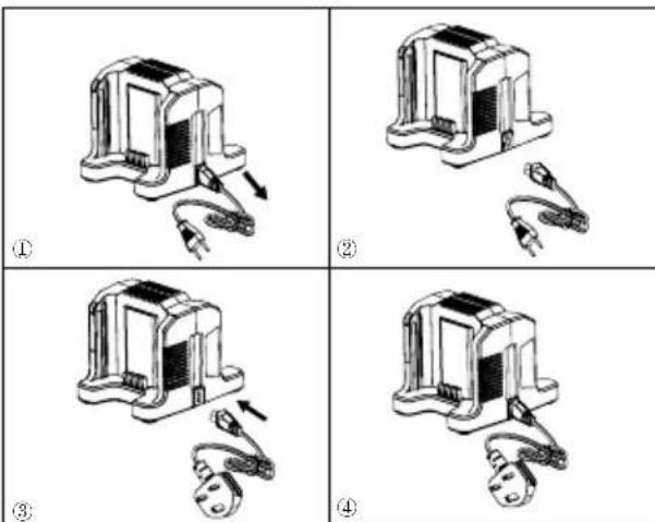
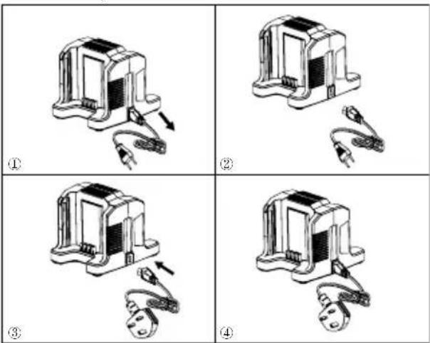
DETACHABLE POWER CORD
The power cords of the charger are detachable. They can be removed from the charger and used interchangeably. (See the figure below)
IMPORTANT SAFETY INSTRUCTIONS
- SAVE THESE INSTRUCTIONS - DANGER: TO REDUCE RISK OF FIRE OR ELECTRIC SHOCK CAREFULLY FOLLOW THESE INSTRUCTIONS.
- Confirm the voltage available at each country location before using the charger.
- If the shape of the plug does not fit the power outlet, use an attachment plug adaptor of the proper configuration for the power outlet.
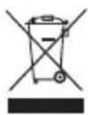
CORRECT DISPOSAL OF THIS PRODUCT:
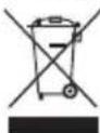
This marking indicates that this product should not be disposed with other household wastes throughout the EU. To prevent possible harm to the environment or human health from uncontrolled waste disposal, recycle it responsibly to promote the sustainable reuse of material resources. To return your used device, please use the return and collection systems or contact the retailer where the
English (Original Instructions)
product was purchased. They can take this product for environmental safe recycling.
REMOVAL OF WASTE BATTERIES AND ACCUMULATORS
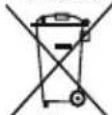
Li-ion
Member States shall ensure that manufacturers design appliances in such a way that waste batteries and accumulators can be readily removed. Where they cannot be readily removed by the end-user. Member States shall ensure that manufacturers design appliances in such a way that waste batteries and accumulators can be readily removed by qualified professionals that are independent of the manufacturer. Appliances in which batteries and accumulators are incorporated shall be accompanied by instructions on how those batteries and accumulators can be safely removed by either the end-user or by independent qualified professionals. Where appropriate, the instructions shall also inform the end-user of the types of battery or accumulator incorporated into the appliance.
text_image
Technical diagram of a device with labeled parts 1, 2, and 3, showing internal components and ventilation slots.
2904813
text_image
Technical diagram of a device with numbered components and labeled parts in Chinese
natural_image
Technical line drawing of a rectangular electronic device with mounting holes and internal components, no text or symbols present.
text_image
Four-panel diagram showing a device with labeled parts and directional arrows, likely illustrating a mechanical or electrical assembly.
text_image
Technical diagram of a device with numbered parts labeled 1, 2, and 3
2904813
- Cargar una batería:
text_image
Technical diagram of a multi-chamber electronic device with numbered components labeled 1, 2, and 3.
natural_image
Technical line drawing of a mechanical or electronic component with mounting holes and a central rectangular housing (no text or symbols)
text_image
Technical diagram of a device with labeled parts 1, 2, and 3, showing internal components and ventilation slots.
2904813
text_image
Technical diagram of a multi-chamber electronic device with numbered components labeled 1, 2, and 3.
natural_image
Technical line drawing of a rectangular electronic device with mounting holes and internal components, no visible text or symbols
text_image
Technical diagram of a device with numbered parts labeled 1, 2, and 3
2904813
text_image
Technical diagram of a server rack with labeled components and numbered parts
text_image
Technical diagram of a device with numbered parts labeled 1, 2, and 3
CORDON D'ALIMENTATION AMOVIBLE
text_image
Four-panel diagram showing a device with labeled parts and directional arrows, likely illustrating a mechanical or electrical assembly.
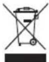
MISE AU REBUT CORRECTE DE CE PRODUIT :
natural_image
Simple diagram of a device with five square buttons and a circular button, no text or symbols present
text_image
Technical diagram of a device with numbered parts labeled 1, 2, and 3
2904813
text_image
Technical diagram of a multi-chamber electronic device with numbered components labeled 1, 2, and 3.
natural_image
Technical line drawing of a rectangular electronic device with mounting brackets and internal components (no text or symbols)
text_image
Four-panel diagram showing mechanical assembly steps with Chinese labels (①, ②, ③, ④) and directional arrows.
INSTRUÇÕES IMPORTANTES DE SEGURANÇA
text_image
Technical diagram of a device with numbered parts labeled 1, 2, and 3
2904813
- Charger two batteries:
text_image
Technical diagram of a device with numbered components, likely an electronic or mechanical assembly.
natural_image
Technical line drawing of a rectangular electronic device with mounting holes and internal components (no text or symbols)
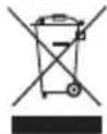
CORRECTE AFVOER VAN DIT PRODUCT:
text_image
Technical diagram of a device with numbered parts labeled 1, 2, and 3
2904813
text_image
Technical diagram of a multi-chamber electronic device with numbered components labeled 1, 2, and 3.
natural_image
Technical line drawing of a mechanical or electronic component with mounting holes and a central square housing (no text or symbols)
text_image
Technical diagram of a device with numbered parts labeled 1, 2, and 3
2904813
text_image
Technical diagram of a multi-chamber electronic device with numbered components labeled 1, 2, and 3.
natural_image
Technical line drawing of a rectangular electronic device with mounting holes and internal components, no text or symbols present.
text_image
Technical diagram of a device with labeled parts 1, 2, and 3, showing internal components and mounting structure.
2904813
text_image
Technical diagram of a device with numbered components labeled 1, 2, and 3
natural_image
Technical line drawing of a rectangular electronic device with mounting brackets and a central component, connected to a cable (no text or symbols)
text_image
Four-panel diagram showing a device with labeled parts and directional arrows, likely illustrating a mechanical or electrical assembly.
VIKTIGA SÄKERHETSFÖRESKRIFTER
Akumulator: 54V = 2.5AH, 135Wh, 60V maks.
text_image
Technical diagram of a device with numbered parts labeled 1, 2, and 3
2904813
- Lad ett batteri:
-Sett inn laderen (1) i et strømuttak.
-Sett batteripakken (2) inn i laderen (1).
- Lad to batterier:
-Sett inn laderen (1) i et strømuttak.
-Sett inn to batteripakker (2) i laderen (1).
text_image
Technical diagram of a device with numbered components labeled 1, 2, and 3
natural_image
Technical line drawing of a mechanical or electronic component with mounting holes and a central rectangular housing (no text or symbols)
text_image
Technical diagram of a device with numbered parts labeled 1, 2, and 3
2904813
text_image
Technical diagram of a device with numbered components labeled 1, 2, and 3
natural_image
Technical line drawing of a rectangular electronic device with mounting holes and a central square component, connected to a cable (no text or symbols)
Akumulator: 54V = 2.0Ah, 108Wh, 60V maks.
Akumulator: 54V = 2.5Ah, 135Wh, 60V maks.
Akumulator: 54V = 3.0Ah, 162Wh, 60V maks.
text_image
Technical diagram of a device with numbered parts labeled 1, 2, and 3
2904813
text_image
Technical diagram of a multi-chamber electronic device with numbered components labeled 1, 2, and 3.
natural_image
Technical line drawing of a rectangular electronic device with mounting holes and internal components, no text or symbols present.
text_image
Four-panel diagram showing a mechanical device with labeled steps ① to ④, illustrating a step-by-step assembly.
WAŻNE INSTRUKCJE DOTYCZĄCE BEZPIECZENSTWA
text_image
Technical diagram of a device with numbered parts labeled 1, 2, and 3
2904813
text_image
Technical diagram of a multi-chamber electronic device with numbered components labeled 1, 2, and 3.
natural_image
Technical line drawing of a device housing with mounting holes and internal components (no text or symbols)
text_image
Four-panel diagram showing mechanical assembly steps with labeled components and directional arrows
DŮLEŽITÉ BEZPEČNOSTNÍ POKYNY
natural_image
Simple line drawing of a device panel with three square buttons and a circular button (no text or symbols)
TLAČIDLO INDIKÁTORA
NABITIA AKUMULÁTORA (ICB)
text_image
Technical diagram of a device with numbered parts labeled 1, 2, and 3
2904813
- Nabíjanie jednej batérie:
text_image
Technical diagram of a device with numbered components and labeled parts
natural_image
Technical line drawing of a rectangular electronic device with mounting holes and internal components, no text or symbols present.
POZN: Pokiaľ mienite akumulátor a dobíjačku nepoužívat’ dlhšiu dobu, odstráňte akumulátor z dobíjačky a odpojte konektor AC.
DÔLEŽITÉ BEZPEČNOSTNÉ POKYNY
- UCHOVAJTE SI TIETO POKYNY NEBEZPEČIE: PRE ZNÍŽENIE RIZIKA POŽIARU ALEBO ELEKTRICKÝCH VÝBOJOVJE POTREBNÉDODRŽIAVAŤ NASLEDUJÚCE POKYNYI.
- Pred použitím dobíjačky preverte aké napätie je dostupné v danej krajine.
- Ak tvar zástrčky nesedí do elektrickej
Akumulator: 54V =2.0Ah, 108Wh, 60V MAX
Akumulator: 54V=2.5Ah, 135Wh, 60V MAX
Akumulator: 54V=3.0Ah, 162Wh, 60V MAX
Akumulator: 54V = 4.0Ah, 216Wh, 60V MAX
Akumulator: 54V = 6.0Ah, 324Wh, 60V MAX
text_image
Technical diagram of a device with labeled parts 1, 2, and 3, showing internal components and ventilation slots.
2904813
text_image
Technical diagram of a device with numbered components labeled 1, 2, and 3
natural_image
Technical line drawing of a rectangular electronic device with mounting holes and internal components, no text or symbols present.
natural_image
Simple diagram of a device panel with four square buttons and a circular button (no text or symbols)
TIPKA INDIKATOR
NAPUNJENOSTI BATERIJE (INB)
MJERENJE
| Svjetla | Stanje napunjenosti |
| 4 zelena svjetla | Napunjenost baterije je veća od 80% |
| 3 zelena svjetla | Napunjenost baterije je između 80% i 60% |
| 2 zelena svjetla | Napunjenost baterije je između 60% i 40% |
| 1 zeleno svjetlo | Napunjenost baterije je između 40% i 20% |
| Svjetla se gase | Napunjenost baterije je manja od 20%Bateriju treba odmah napuniti. |
SIGURNOSNE NAPOMENE I MJERE OPREZA
- NE rastavljajte bateriju.
- Držite izvan dohvata djece.
- Bateriju NE izlažite slanoj ili slatkoj vodi, pohranite je na hladnom i suhom mjestu.
- Bateriju NE stavljajte blizu suviše toplih mjesta na primjer u blizini vatre ili radijatora.
- NE mjenjajte pozitivni i negativni pol baterije.
- NE povezujte polove baterije, negativni i pozitivni, s metalnim predmetima.
- Bateriju NEMOJTE udarati niti gaziti nogama.
- Na bateriji NEMOJTE obavljati zavarivanje, NEMOJTE je bušiti čavlima ili drugim oštrim predmetima.
- Ako iz baterije curi tekućina i ako ona dođe u kontakt s očima, nemojte ih
trljati i temeljno ih isperite vodom. Prekinite uporabu baterije ako ona ima neuobičajen miris, ako se pregrijava, menja boju/oblik i ako ima neuobičajen izlged.
PUNJAČ ZA BATERIJE
KARAKTERISTIKE
Punjač od 60V: 2900313
Ulaz: 220-240V \~50/60Hz 1A
Izlaz: 60V=2A
Punjač od 60V: 2904813
Ulaz: 220-240V \~50/60Hz 2A
Izlaz: 60V =4A
■ NE ispitujte punjač provodljivim materijalima.
■ NE dopustite da tekućina prodre unutar punjača.
■ NE koristite punjač u svrhe koje nisu navedene u ovom priručniku.
■ Isključite punjač prije čišćenja i kada nema baterije u punjaču.
■ Nemojte pokušavati spojiti dva punjača zajedno.
■ Nemojte koristiti u slučaju da izlazni polaritet ne odgovara polaritetu opterećenja.
■ Samo za korištenje u zatvorenom.
■ Pokrov ni pod kojim uvjetima ne smije biti otvoren. Ako je pokrov oštećen, punjač se ne smije više koristiti.
■ Nemojte ponovno puniti nepunjive baterije.
POZOR
Kako bi se izbjegla opasnost od požara ili strujnog udara:
- Bateriju i punjač ne perite vlažnim krpama ili deterdžentom.
- Prije čišćenja, kontrole i obavljanja održavanja uređaja, uvijek iz njega izvadite bateriju.
text_image
Technical diagram of a device with numbered parts labeled 1, 2, and 3
2904813
- Punjenje jedne baterije:
-Útaknite punjač (1) u odgovarajuću električnu zidnu utičnicu.
-Umetnite bateriju (2) u punjač (1).
text_image
Technical diagram of a device with numbered components labeled 1, 2, and 3
natural_image
Technical line drawing of a rectangular electronic device with mounting holes and internal components, no text or symbols present.
NAPOMENA: Ako punjač i bateriju ne koristite duže vrijeme, izvadite bateriju iz punjača i punjač iskopčajte iz strujne utičnice.
ODSPOJIVI KABEL ZA NAPAJANJE
Kabeli za napajanje punjača se mogu odspojiti. Mogu se ukloniti s punjača i koristiti samostalno. (pogledajte sliku u nastavku)
text_image
Four-panel diagram showing a device with labeled parts and directional arrows, likely illustrating a mechanical or electrical assembly.
VAŽNI SIGURNOSNI UPUTI
- SAČUVAJTE OVE UPUTE OPASNOST: KAKO BI SE SMANJIO RIZIK OD POŽARA ILI STRUJNOG UDARA, VAŽNO JE PAŽLJIVO SLIJEDITI OVE UPUTE.
- Prije uporabe punjača provjerite napon dostupan u svakoj zemlji korištenja.
- Ako oblik utikača ne odgovara utičnici za napajanje, koristite prkiljučak adaptera za utičnicu za pravilnu konfiguraciju utičnice za napajanje.
natural_image
Simple diagram of a device panel with four square buttons and a circular button, no text or symbols present.
ÉRÉS
AKKUMULÁTORTÖLTÓM
JELZŐ GOMB (ICB)
text_image
Technical diagram of a device with labeled parts 1, 2, and 3, showing internal components and ventilation slots.
2904813
text_image
Technical diagram of a device with numbered components labeled 1, 2, and 3
natural_image
Technical line drawing of a mechanical or electronic component with mounting holes and a central rectangular housing (no text or symbols)
text_image
Four-panel diagram showing a device with labeled parts and directional arrows, likely illustrating a mechanical or electrical assembly.
FONTOS BIZTONSÁGI UTASÍTÁSOK
natural_image
Simple line drawing of a device panel with four square buttons and a circular button (no text or symbols)
TASTĂ PENTRU
ÎNCĂRCĂTOR (ICB)
text_image
Technical diagram of a device with numbered parts labeled 1, 2, and 3
2904813
text_image
Technical diagram of a multi-chamber electronic device with numbered components labeled 1, 2, and 3.
natural_image
Technical line drawing of a mechanical or electronic component with mounting holes and a central rectangular housing (no text or symbols)
natural_image
Simple diagram of a device panel with three buttons and a circular indicator (no text or symbols)
БУТОН ИНДИКАТОР
ЗАРЯДНО
УСТРОЙСТВО (ICB)
text_image
Technical diagram of a device with labeled parts, showing internal components and labeled parts 1 and 2.
text_image
Technical diagram of a server rack with numbered components labeled 1, 2, and 3
natural_image
Technical line drawing of a mechanical or electronic component with mounting holes and a central rectangular housing (no text or symbols)
natural_image
Simple diagram of a device panel with two labeled buttons and four square buttons (no text or symbols)
text_image
Technical diagram of a device with labeled parts 1, 2, and 3, showing internal components and ventilation slots.
2904813
text_image
Technical diagram of a multi-chamber electronic device with numbered components labeled 1, 2, and 3.
natural_image
Technical line drawing of a rectangular electronic device with mounting holes and a central internal component, connected to a cable (no text or symbols present)
مخرج: 60select 4Ambyer
text_image
Technical diagram of a device with labeled parts 1, 2, and 3, showing internal components and ventilation slots.
2904813
text_image
Technical diagram of a server rack with numbered components and labeled parts
natural_image
Technical line drawing of a rectangular electronic device with mounting holes and internal components, no text or symbols present.
text_image
Four-panel diagram showing a mechanical component with labeled parts and directional arrows, likely illustrating a step-by-step assembly or disassembly process.
تعليمات أمنية هامة:
natural_image
Simple line drawing of a device panel with three buttons and a circular button (no text or symbols)
PİL ŞARJ GÖSTERGESİ LÇÜM
(PŞG) TUŞU
text_image
Technical diagram of a device with labeled parts, showing internal components and labeled parts 1 and 2.
2904813
text_image
Technical diagram of a device with numbered components labeled 1, 2, and 3
natural_image
Technical line drawing of a rectangular electronic device with mounting holes and a central internal component, connected to a cable (no text or symbols)
text_image
Four-panel diagram showing a mechanical device with labeled parts, illustrating assembly or disassembly steps.
text_image
Diagram showing a device panel with labeled buttons and a circular icon containing a letter 'B'.
.הכלההוּרָהוּרָהוּרָהוּרָהוּרָהוּרָהוּרָהוּרָהוּרָהוּרָהוּרָהוּרָהוּרָהוּרָהוּרָה
(בַרְׁה בָרִי)
text_image
Technical diagram of a device with labeled parts, showing internal components and labeled parts 1 and 2.
2904813
text_image
Technical diagram of a device with numbered components labeled 1, 2, and 3
natural_image
Technical line drawing of a rectangular electronic device with mounting holes and internal components, no text or symbols present.
text_image
Four-panel diagram showing a device with labeled parts and directional arrows, likely illustrating a mechanical or electrical assembly process.
natural_image
Simple line drawing of a device panel with four square buttons and a circular button (no text or symbols)
AKUMULIATORIAUS M ATAVIMAS
KROVIKLIO INDIKATORIUS (ICB)
text_image
Technical diagram of a device with numbered parts labeled 1, 2, and 3
2904813
text_image
Technical diagram of a server rack with labeled components and numbered parts
If the battery is inserted into the charger when warm or hot, the CHARGING LED indicator light on the charger may switch on and illuminate RED. If this occurs allow the battery to cool outside of the charger from approximately 30 minutes.
JKROVIKLIO MONTAVIMAS
natural_image
Technical line drawing of a rectangular electronic device with mounting holes and internal components, no text or symbols present.
CORRECT DISPOSAL OF THIS PRODUCT:
text_image
Diagram showing a device panel with labeled buttons and a circular icon containing a vertical bar, likely indicating a status or function.
AKUMULATORA UZLÃDES
LÎMENA INDIKATORA (ICB)
TAUSTINŠ
MÉRÎJUMS
text_image
Technical diagram of a device with labeled parts 1, 2, and 3, showing internal components and ventilation slots.
2904813
text_image
Technical diagram of a server rack with numbered components and labeled parts
natural_image
Technical line drawing of a rectangular electronic device with mounting holes and internal components, connected to a cable (no text or symbols)
natural_image
Simple diagram of a device panel with four square buttons and a circular button, no text or symbols present.
AKULAETUVUSE
KONTROLLNUPP (ICB)
MÕÖTMINE
text_image
Technical diagram of a device with labeled parts, showing internal components and mounting points.
2904813
text_image
Technical diagram of a device with numbered components, likely an electronic or mechanical assembly.
natural_image
Technical line drawing of a device housing with mounting holes and a central rectangular component, no text or symbols present.
All new Powerworks Tools machinery is supplied with a 2 year parts and labour warranty from original date of purchase. A 30 day warranty is available for machines used professionally as Powerworks Tools are designed primarily to be used by DIY consumers.
This warranty is non-transferable.
LIMITATIONS
This warranty applies only to defective parts/components and does not cover repairs due to:
- Normal wear and tear.
- Routine tune up or adjustment.
- Damage caused by improper handling/abuse/misuse or neglect.
- Overheating due to lack of maintenance.
- Damage due to fittings/fasteners becoming loose/detached through lack of maintenance.
- Damage caused by cleaning with water.
- Machines serviced or repaired by non-authorised Powerworks Tools service centres.
- Machines incorrectly assembled or adjusted.
- Damage caused by improper use of the machine.
- Damage caused by improper winterisation (pressure washers)
-
Items considered as consumable parts are not normally covered by the warranty, including but not limited to:
-
Batteries
- Electric cables
- Blade and blade assemblies
- Belts
-
Filters
• Chucks and tool holders
-
Certain products may contain components such as engines, transmissions from an alternative manufacturer, these items will be subject to the appropriate manufacturer's warranty policy except where Greenworks Tools Europe GmbH agrees to underwrite any claims outside the said manufacturer's warranty period.
-
Second hand goods are not covered under this warranty policy.
- The fitting of spares, replacements or extra components which are not supplied or approved by Greenworks Tools Europe GmbH.
Warranty
To claim a warranty on any product under this policy a proof of original purchase is required. Credit card statement do not qualify as sufficient proof of purchase. In the first instance of a warranty event occurring the consumer should return the product to the original place of purchase with their proof of purchase. The machine will be sent to our central service facility and an inspection made. If the machine be found to be at fault it will be repaired and sent back to the address of the consumer free of charge. Machines that retail for less than €100 euros including sales taxes will generally be replaced.
If the central service facility finds that machine is not found to be at fault then the consumer will be advised they will need to pay for the cost of the repair.
This warranty policy is subject to change from time to time to accommodate the needs of new products. A copy of the latest warranty policy will be available at www.greenworkstools.eu.

12 Greenworks and Software Tools Europe GmbH
Manufacturer: Changzhou Globe Co., Ltd.
Address: No.65 Xinggang Road Zhonglou Zone Changzhou, Jiangsu 213000 P.R.China
Name and address of the person authorised to compile the technical file:
Name: Peter Söderström
Address: Hjortronvägen 3, 555 93 Jönköping, Sweden
Herewith we declare that the product
Category: 60V battery charger
Model: 2900313/2904813
Serial number: See product rating label
Year of Construction: See product rating label
■ is in conformit with the relevant provisions of the Low Voltage Directive 2014/35/EU
■ is in conformit with the provisions of the following other EMC directive (2014/30/EU).
And furthermore, we declare that
the following (parts/clauses of) European harmonised standards have been used
EN 60335-2-29, EN 60335-1, EN 62233, EN 55014-1,
EN 55014-2, EN 61000-3-2, EN 61000-3-3
Place, date: Changzhou, 26/10/2017
Signature: Ted Qu Haichao
Quality Director
Ted Qu

Fabricant: Changzhou Globe Co., Ltd.
Adresse : No.65 Xinggang Road Zhonglou Zone Changzhou, Jiangsu 213000 R. P. de Chine
Endereço: No.65 Xinggang Road Zhonglou Zone Changzhou, Jiangsu 213000 China
DEKLARACJA ZGODNOŚCI WE
Producent: Changzhou Globe Co., Ltd.
Adres: Nr 65 Xinggang Road Zhonglou Zone Changzhou, Jiangsu 213000, ChRL
Naslov: No. 65 Xinggang Rd., Zhonglou Zone, Changzhou, Jiangsu, Kitajska
Adresa: No.65 Xinggang Road Zhonglou Zone Changzhou, Jiangsu 213000, Republica Populară Chineză
Adrese: No.65 Xinggang Road Zhonglou Zone Changzhou, Jiangsu 213000 P.R.China